EP3275715A1 - Cruise control device and cruise control method - Google Patents
Cruise control device and cruise control method Download PDFInfo
- Publication number
- EP3275715A1 EP3275715A1 EP16768653.4A EP16768653A EP3275715A1 EP 3275715 A1 EP3275715 A1 EP 3275715A1 EP 16768653 A EP16768653 A EP 16768653A EP 3275715 A1 EP3275715 A1 EP 3275715A1
- Authority
- EP
- European Patent Office
- Prior art keywords
- vehicle
- speed
- section
- road
- opening
- Prior art date
- Legal status (The legal status is an assumption and is not a legal conclusion. Google has not performed a legal analysis and makes no representation as to the accuracy of the status listed.)
- Granted
Links
Images


Classifications
-
- B—PERFORMING OPERATIONS; TRANSPORTING
- B60—VEHICLES IN GENERAL
- B60W—CONJOINT CONTROL OF VEHICLE SUB-UNITS OF DIFFERENT TYPE OR DIFFERENT FUNCTION; CONTROL SYSTEMS SPECIALLY ADAPTED FOR HYBRID VEHICLES; ROAD VEHICLE DRIVE CONTROL SYSTEMS FOR PURPOSES NOT RELATED TO THE CONTROL OF A PARTICULAR SUB-UNIT
- B60W30/00—Purposes of road vehicle drive control systems not related to the control of a particular sub-unit, e.g. of systems using conjoint control of vehicle sub-units
- B60W30/14—Adaptive cruise control
- B60W30/143—Speed control
-
- B—PERFORMING OPERATIONS; TRANSPORTING
- B60—VEHICLES IN GENERAL
- B60K—ARRANGEMENT OR MOUNTING OF PROPULSION UNITS OR OF TRANSMISSIONS IN VEHICLES; ARRANGEMENT OR MOUNTING OF PLURAL DIVERSE PRIME-MOVERS IN VEHICLES; AUXILIARY DRIVES FOR VEHICLES; INSTRUMENTATION OR DASHBOARDS FOR VEHICLES; ARRANGEMENTS IN CONNECTION WITH COOLING, AIR INTAKE, GAS EXHAUST OR FUEL SUPPLY OF PROPULSION UNITS IN VEHICLES
- B60K31/00—Vehicle fittings, acting on a single sub-unit only, for automatically controlling vehicle speed, i.e. preventing speed from exceeding an arbitrarily established velocity or maintaining speed at a particular velocity, as selected by the vehicle operator
-
- B—PERFORMING OPERATIONS; TRANSPORTING
- B60—VEHICLES IN GENERAL
- B60W—CONJOINT CONTROL OF VEHICLE SUB-UNITS OF DIFFERENT TYPE OR DIFFERENT FUNCTION; CONTROL SYSTEMS SPECIALLY ADAPTED FOR HYBRID VEHICLES; ROAD VEHICLE DRIVE CONTROL SYSTEMS FOR PURPOSES NOT RELATED TO THE CONTROL OF A PARTICULAR SUB-UNIT
- B60W40/00—Estimation or calculation of non-directly measurable driving parameters for road vehicle drive control systems not related to the control of a particular sub unit, e.g. by using mathematical models
- B60W40/02—Estimation or calculation of non-directly measurable driving parameters for road vehicle drive control systems not related to the control of a particular sub unit, e.g. by using mathematical models related to ambient conditions
- B60W40/06—Road conditions
- B60W40/076—Slope angle of the road
-
- B—PERFORMING OPERATIONS; TRANSPORTING
- B60—VEHICLES IN GENERAL
- B60W—CONJOINT CONTROL OF VEHICLE SUB-UNITS OF DIFFERENT TYPE OR DIFFERENT FUNCTION; CONTROL SYSTEMS SPECIALLY ADAPTED FOR HYBRID VEHICLES; ROAD VEHICLE DRIVE CONTROL SYSTEMS FOR PURPOSES NOT RELATED TO THE CONTROL OF A PARTICULAR SUB-UNIT
- B60W40/00—Estimation or calculation of non-directly measurable driving parameters for road vehicle drive control systems not related to the control of a particular sub unit, e.g. by using mathematical models
- B60W40/10—Estimation or calculation of non-directly measurable driving parameters for road vehicle drive control systems not related to the control of a particular sub unit, e.g. by using mathematical models related to vehicle motion
- B60W40/105—Speed
-
- B—PERFORMING OPERATIONS; TRANSPORTING
- B60—VEHICLES IN GENERAL
- B60W—CONJOINT CONTROL OF VEHICLE SUB-UNITS OF DIFFERENT TYPE OR DIFFERENT FUNCTION; CONTROL SYSTEMS SPECIALLY ADAPTED FOR HYBRID VEHICLES; ROAD VEHICLE DRIVE CONTROL SYSTEMS FOR PURPOSES NOT RELATED TO THE CONTROL OF A PARTICULAR SUB-UNIT
- B60W50/00—Details of control systems for road vehicle drive control not related to the control of a particular sub-unit, e.g. process diagnostic or vehicle driver interfaces
- B60W50/0097—Predicting future conditions
-
- G—PHYSICS
- G06—COMPUTING OR CALCULATING; COUNTING
- G06V—IMAGE OR VIDEO RECOGNITION OR UNDERSTANDING
- G06V20/00—Scenes; Scene-specific elements
- G06V20/50—Context or environment of the image
- G06V20/56—Context or environment of the image exterior to a vehicle by using sensors mounted on the vehicle
-
- B—PERFORMING OPERATIONS; TRANSPORTING
- B60—VEHICLES IN GENERAL
- B60W—CONJOINT CONTROL OF VEHICLE SUB-UNITS OF DIFFERENT TYPE OR DIFFERENT FUNCTION; CONTROL SYSTEMS SPECIALLY ADAPTED FOR HYBRID VEHICLES; ROAD VEHICLE DRIVE CONTROL SYSTEMS FOR PURPOSES NOT RELATED TO THE CONTROL OF A PARTICULAR SUB-UNIT
- B60W50/00—Details of control systems for road vehicle drive control not related to the control of a particular sub-unit, e.g. process diagnostic or vehicle driver interfaces
- B60W2050/0001—Details of the control system
- B60W2050/0002—Automatic control, details of type of controller or control system architecture
- B60W2050/0012—Feedforward or open loop systems
-
- B—PERFORMING OPERATIONS; TRANSPORTING
- B60—VEHICLES IN GENERAL
- B60W—CONJOINT CONTROL OF VEHICLE SUB-UNITS OF DIFFERENT TYPE OR DIFFERENT FUNCTION; CONTROL SYSTEMS SPECIALLY ADAPTED FOR HYBRID VEHICLES; ROAD VEHICLE DRIVE CONTROL SYSTEMS FOR PURPOSES NOT RELATED TO THE CONTROL OF A PARTICULAR SUB-UNIT
- B60W50/00—Details of control systems for road vehicle drive control not related to the control of a particular sub-unit, e.g. process diagnostic or vehicle driver interfaces
- B60W2050/0001—Details of the control system
- B60W2050/0002—Automatic control, details of type of controller or control system architecture
- B60W2050/0014—Adaptive controllers
-
- B—PERFORMING OPERATIONS; TRANSPORTING
- B60—VEHICLES IN GENERAL
- B60W—CONJOINT CONTROL OF VEHICLE SUB-UNITS OF DIFFERENT TYPE OR DIFFERENT FUNCTION; CONTROL SYSTEMS SPECIALLY ADAPTED FOR HYBRID VEHICLES; ROAD VEHICLE DRIVE CONTROL SYSTEMS FOR PURPOSES NOT RELATED TO THE CONTROL OF A PARTICULAR SUB-UNIT
- B60W2510/00—Input parameters relating to a particular sub-units
- B60W2510/06—Combustion engines, Gas turbines
- B60W2510/0666—Engine power
-
- B—PERFORMING OPERATIONS; TRANSPORTING
- B60—VEHICLES IN GENERAL
- B60W—CONJOINT CONTROL OF VEHICLE SUB-UNITS OF DIFFERENT TYPE OR DIFFERENT FUNCTION; CONTROL SYSTEMS SPECIALLY ADAPTED FOR HYBRID VEHICLES; ROAD VEHICLE DRIVE CONTROL SYSTEMS FOR PURPOSES NOT RELATED TO THE CONTROL OF A PARTICULAR SUB-UNIT
- B60W2510/00—Input parameters relating to a particular sub-units
- B60W2510/10—Change speed gearings
- B60W2510/1005—Transmission ratio engaged
-
- B—PERFORMING OPERATIONS; TRANSPORTING
- B60—VEHICLES IN GENERAL
- B60W—CONJOINT CONTROL OF VEHICLE SUB-UNITS OF DIFFERENT TYPE OR DIFFERENT FUNCTION; CONTROL SYSTEMS SPECIALLY ADAPTED FOR HYBRID VEHICLES; ROAD VEHICLE DRIVE CONTROL SYSTEMS FOR PURPOSES NOT RELATED TO THE CONTROL OF A PARTICULAR SUB-UNIT
- B60W2520/00—Input parameters relating to overall vehicle dynamics
- B60W2520/10—Longitudinal speed
-
- B—PERFORMING OPERATIONS; TRANSPORTING
- B60—VEHICLES IN GENERAL
- B60W—CONJOINT CONTROL OF VEHICLE SUB-UNITS OF DIFFERENT TYPE OR DIFFERENT FUNCTION; CONTROL SYSTEMS SPECIALLY ADAPTED FOR HYBRID VEHICLES; ROAD VEHICLE DRIVE CONTROL SYSTEMS FOR PURPOSES NOT RELATED TO THE CONTROL OF A PARTICULAR SUB-UNIT
- B60W2530/00—Input parameters relating to vehicle conditions or values, not covered by groups B60W2510/00 or B60W2520/00
- B60W2530/10—Weight
-
- B—PERFORMING OPERATIONS; TRANSPORTING
- B60—VEHICLES IN GENERAL
- B60W—CONJOINT CONTROL OF VEHICLE SUB-UNITS OF DIFFERENT TYPE OR DIFFERENT FUNCTION; CONTROL SYSTEMS SPECIALLY ADAPTED FOR HYBRID VEHICLES; ROAD VEHICLE DRIVE CONTROL SYSTEMS FOR PURPOSES NOT RELATED TO THE CONTROL OF A PARTICULAR SUB-UNIT
- B60W2540/00—Input parameters relating to occupants
- B60W2540/10—Accelerator pedal position
-
- B—PERFORMING OPERATIONS; TRANSPORTING
- B60—VEHICLES IN GENERAL
- B60W—CONJOINT CONTROL OF VEHICLE SUB-UNITS OF DIFFERENT TYPE OR DIFFERENT FUNCTION; CONTROL SYSTEMS SPECIALLY ADAPTED FOR HYBRID VEHICLES; ROAD VEHICLE DRIVE CONTROL SYSTEMS FOR PURPOSES NOT RELATED TO THE CONTROL OF A PARTICULAR SUB-UNIT
- B60W2540/00—Input parameters relating to occupants
- B60W2540/12—Brake pedal position
-
- B—PERFORMING OPERATIONS; TRANSPORTING
- B60—VEHICLES IN GENERAL
- B60W—CONJOINT CONTROL OF VEHICLE SUB-UNITS OF DIFFERENT TYPE OR DIFFERENT FUNCTION; CONTROL SYSTEMS SPECIALLY ADAPTED FOR HYBRID VEHICLES; ROAD VEHICLE DRIVE CONTROL SYSTEMS FOR PURPOSES NOT RELATED TO THE CONTROL OF A PARTICULAR SUB-UNIT
- B60W2540/00—Input parameters relating to occupants
- B60W2540/16—Ratio selector position
-
- B—PERFORMING OPERATIONS; TRANSPORTING
- B60—VEHICLES IN GENERAL
- B60W—CONJOINT CONTROL OF VEHICLE SUB-UNITS OF DIFFERENT TYPE OR DIFFERENT FUNCTION; CONTROL SYSTEMS SPECIALLY ADAPTED FOR HYBRID VEHICLES; ROAD VEHICLE DRIVE CONTROL SYSTEMS FOR PURPOSES NOT RELATED TO THE CONTROL OF A PARTICULAR SUB-UNIT
- B60W2540/00—Input parameters relating to occupants
- B60W2540/20—Direction indicator values
-
- B—PERFORMING OPERATIONS; TRANSPORTING
- B60—VEHICLES IN GENERAL
- B60W—CONJOINT CONTROL OF VEHICLE SUB-UNITS OF DIFFERENT TYPE OR DIFFERENT FUNCTION; CONTROL SYSTEMS SPECIALLY ADAPTED FOR HYBRID VEHICLES; ROAD VEHICLE DRIVE CONTROL SYSTEMS FOR PURPOSES NOT RELATED TO THE CONTROL OF A PARTICULAR SUB-UNIT
- B60W2552/00—Input parameters relating to infrastructure
- B60W2552/15—Road slope, i.e. the inclination of a road segment in the longitudinal direction
-
- B—PERFORMING OPERATIONS; TRANSPORTING
- B60—VEHICLES IN GENERAL
- B60W—CONJOINT CONTROL OF VEHICLE SUB-UNITS OF DIFFERENT TYPE OR DIFFERENT FUNCTION; CONTROL SYSTEMS SPECIALLY ADAPTED FOR HYBRID VEHICLES; ROAD VEHICLE DRIVE CONTROL SYSTEMS FOR PURPOSES NOT RELATED TO THE CONTROL OF A PARTICULAR SUB-UNIT
- B60W2552/00—Input parameters relating to infrastructure
- B60W2552/30—Road curve radius
-
- B—PERFORMING OPERATIONS; TRANSPORTING
- B60—VEHICLES IN GENERAL
- B60W—CONJOINT CONTROL OF VEHICLE SUB-UNITS OF DIFFERENT TYPE OR DIFFERENT FUNCTION; CONTROL SYSTEMS SPECIALLY ADAPTED FOR HYBRID VEHICLES; ROAD VEHICLE DRIVE CONTROL SYSTEMS FOR PURPOSES NOT RELATED TO THE CONTROL OF A PARTICULAR SUB-UNIT
- B60W2554/00—Input parameters relating to objects
- B60W2554/80—Spatial relation or speed relative to objects
- B60W2554/801—Lateral distance
-
- B—PERFORMING OPERATIONS; TRANSPORTING
- B60—VEHICLES IN GENERAL
- B60W—CONJOINT CONTROL OF VEHICLE SUB-UNITS OF DIFFERENT TYPE OR DIFFERENT FUNCTION; CONTROL SYSTEMS SPECIALLY ADAPTED FOR HYBRID VEHICLES; ROAD VEHICLE DRIVE CONTROL SYSTEMS FOR PURPOSES NOT RELATED TO THE CONTROL OF A PARTICULAR SUB-UNIT
- B60W2555/00—Input parameters relating to exterior conditions, not covered by groups B60W2552/00, B60W2554/00
- B60W2555/60—Traffic rules, e.g. speed limits or right of way
-
- B—PERFORMING OPERATIONS; TRANSPORTING
- B60—VEHICLES IN GENERAL
- B60W—CONJOINT CONTROL OF VEHICLE SUB-UNITS OF DIFFERENT TYPE OR DIFFERENT FUNCTION; CONTROL SYSTEMS SPECIALLY ADAPTED FOR HYBRID VEHICLES; ROAD VEHICLE DRIVE CONTROL SYSTEMS FOR PURPOSES NOT RELATED TO THE CONTROL OF A PARTICULAR SUB-UNIT
- B60W2556/00—Input parameters relating to data
- B60W2556/45—External transmission of data to or from the vehicle
- B60W2556/50—External transmission of data to or from the vehicle of positioning data, e.g. GPS [Global Positioning System] data
-
- B—PERFORMING OPERATIONS; TRANSPORTING
- B60—VEHICLES IN GENERAL
- B60W—CONJOINT CONTROL OF VEHICLE SUB-UNITS OF DIFFERENT TYPE OR DIFFERENT FUNCTION; CONTROL SYSTEMS SPECIALLY ADAPTED FOR HYBRID VEHICLES; ROAD VEHICLE DRIVE CONTROL SYSTEMS FOR PURPOSES NOT RELATED TO THE CONTROL OF A PARTICULAR SUB-UNIT
- B60W2710/00—Output or target parameters relating to a particular sub-units
- B60W2710/06—Combustion engines, Gas turbines
- B60W2710/0605—Throttle position
-
- B—PERFORMING OPERATIONS; TRANSPORTING
- B60—VEHICLES IN GENERAL
- B60W—CONJOINT CONTROL OF VEHICLE SUB-UNITS OF DIFFERENT TYPE OR DIFFERENT FUNCTION; CONTROL SYSTEMS SPECIALLY ADAPTED FOR HYBRID VEHICLES; ROAD VEHICLE DRIVE CONTROL SYSTEMS FOR PURPOSES NOT RELATED TO THE CONTROL OF A PARTICULAR SUB-UNIT
- B60W2720/00—Output or target parameters relating to overall vehicle dynamics
- B60W2720/10—Longitudinal speed
-
- Y—GENERAL TAGGING OF NEW TECHNOLOGICAL DEVELOPMENTS; GENERAL TAGGING OF CROSS-SECTIONAL TECHNOLOGIES SPANNING OVER SEVERAL SECTIONS OF THE IPC; TECHNICAL SUBJECTS COVERED BY FORMER USPC CROSS-REFERENCE ART COLLECTIONS [XRACs] AND DIGESTS
- Y02—TECHNOLOGIES OR APPLICATIONS FOR MITIGATION OR ADAPTATION AGAINST CLIMATE CHANGE
- Y02T—CLIMATE CHANGE MITIGATION TECHNOLOGIES RELATED TO TRANSPORTATION
- Y02T10/00—Road transport of goods or passengers
- Y02T10/10—Internal combustion engine [ICE] based vehicles
- Y02T10/40—Engine management systems
-
- Y—GENERAL TAGGING OF NEW TECHNOLOGICAL DEVELOPMENTS; GENERAL TAGGING OF CROSS-SECTIONAL TECHNOLOGIES SPANNING OVER SEVERAL SECTIONS OF THE IPC; TECHNICAL SUBJECTS COVERED BY FORMER USPC CROSS-REFERENCE ART COLLECTIONS [XRACs] AND DIGESTS
- Y02—TECHNOLOGIES OR APPLICATIONS FOR MITIGATION OR ADAPTATION AGAINST CLIMATE CHANGE
- Y02T—CLIMATE CHANGE MITIGATION TECHNOLOGIES RELATED TO TRANSPORTATION
- Y02T10/00—Road transport of goods or passengers
- Y02T10/80—Technologies aiming to reduce greenhouse gasses emissions common to all road transportation technologies
- Y02T10/84—Data processing systems or methods, management, administration
Definitions
- the present invention relates to a travel control device and a travel control method for controlling a travel of a vehicle such that the vehicle speed is set to a target speed.
- PTL 1 discloses an auto-cruising control device that prevents the vehicle speed from being varied at the time when the vehicle travels from a level ground into a slope so as not to make the passenger uncomfortable.
- this auto-cruising control device images the forward area in the travelling direction of the vehicle with an imaging device, and detects the road grade from the obtained image. Then, the auto-cruising control device calculates a fuel injection amount which does not cause the variation of the vehicle speed from the road grade and the target speed, and drives the engine at that fuel injection amount from a position before the slope.
- the above-described conventional technique disclosed in PTL 1 detects the road grade based on the image imaged with the imaging device, and therefore, in the case of a road including an upslope, a downslope and another upslope in this order, the road grade cannot be easily detected. As a result, there is a risk that the fuel injection amount is not appropriately calculated and the fuel economy is degraded.
- an object of the present invention is to provide a travel control device and a travel control method which can control the vehicle to go up an upslope road without degrading the fuel economy, and can shorten the period until the vehicle reaches the crest while avoiding an unnecessary downshift even in the case where the vehicle travels on an upslope road in which the road grade changes in a certain section.
- a travel control device of an embodiment of the present invention controls a travel of a vehicle such that a vehicle speed is set to a target speed
- the travel control device including: an road information acquiring section that acquires information of a road in a predetermined section ahead of the vehicle that travels with an accelerator opening of a first opening; a vehicle information acquiring section that acquires information of the vehicle; a speed estimating section that estimates based on the information of the road and the information of the vehicle a transition of a vehicle speed in the predetermined section of a case where the vehicle travels with the accelerator opening of a second opening that is greater than the first opening; and an accelerator control section that sets the accelerator opening of the vehicle to the second opening when a minimum value of a vehicle speed estimated by the speed estimating section is smaller than the target speed.
- a travel control method of an embodiment of the present invention is a method for controlling a travel of a vehicle such that a vehicle speed is set to a target speed, the method including: acquiring information of a road in a predetermined section ahead of the vehicle that travels with an accelerator opening of a first opening; acquiring information of the vehicle; estimating based on the information of the road and the information of the vehicle a transition of a vehicle speed in the predetermined section of a case where the vehicle travels with the accelerator opening of a second opening that is greater than the first opening; and setting the accelerator opening of the vehicle to the second opening when a minimum value of a vehicle speed estimated by the estimating is smaller than the target speed.
- the vehicle can go up the upslope road without degrading the fuel economy, and the period until the vehicle reaches the crest can be shortened while avoiding an unnecessary downshift.
- FIG 1 is a block diagram illustrating an example configuration of automatic travel device 2 according to the embodiment of the present invention.
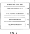
- FIG. 2 is a block diagram illustrating an example configuration of automatic travel control device 12 illustrated in FIG. 1 .
- engine 3 is an in-line six-cylinder diesel engine in FIG. 1
- the present invention is applicable also to a gasoline engine, and the arrangement and the number of the cylinders are not limited.
- vehicle 1 is a large vehicle such as a truck in which a diesel engine is mounted in the following description, the present invention is not limited to large vehicles such as trucks.
- the power of engine 3 is transmitted to transmission 5 via clutch 4, and transmitted from transmission 5 to differential gear 7 through a propeller shaft 6, and further, transmitted from differential gear 7 to wheel 9 through drive shaft 8. In this manner, the power of engine 3 is transmitted to wheel 9, and thus vehicle 1 travels.
- Automatic travel device 2 of the present embodiment controls the output of engine 3, the connection and disconnection of clutch 4, and the transmission of transmission 5 for the automatic travel of vehicle 1.
- Automatic travel device 2 includes a plurality of control devices.
- automatic travel device 2 includes control engine ECU (engine control unit) 10 that controls the output of engine 3, power transferring ECU (power transferring control unit) 11 that controls the connection and disconnection of clutch 4 and the transmission of transmission 5, and automatic travel control device 12 that controls the automatic travel of vehicle 1.
- control engine ECU engine control unit
- power transferring ECU power transferring control unit
- automatic travel control device 12 that controls the automatic travel of vehicle 1.
- Each of engine ECU 10, power transferring ECU 11, and automatic travel control device 12 is composed of a micro controller.
- Engine ECU 10, power transferring ECU 11, and automatic travel control device 12 are connected with one another with an in-vehicle network, and required data and control signals are exchanged therebetween.
- automatic travel device 2 includes, at a dashboard of a driver's seat not illustrated, target-vehicle speed setting device 13 and increment/reduction value setting device 14, and target-vehicle speed setting device 13 and increment/reduction value setting device 14 are connected with automatic travel control device 12.
- Target-vehicle speed setting device 13 is a device that is manually operated by the driver before the automatic travel of vehicle 1 is started, to set target-vehicle speed V' [km/h] of vehicle 1 in the automatic travel.
- target-vehicle speed V' is set in target-vehicle speed setting device 13 by the driver, the target-vehicle speed V' is transmitted to automatic travel control device 12, and stored in a storage device of automatic travel control device 12.
- Increment/reduction value setting device 14 is a device that is operated by the driver before the automatic travel of vehicle 1 is started and after target-vehicle speed V' is set, to set both speed reduction value -va [km/h] and speed increment value +vb [km/h] of vehicle 1 in the automatic travel.
- speed reduction value -va and speed increment value +vb are set in increment/reduction value setting device 14 by the driver, speed reduction value -va and speed increment value +vb are transmitted to automatic travel control device 12, and stored in a storage device of automatic travel control device 12.
- automatic travel control device 12 adds speed reduction value -va and speed increment value +vb to target-vehicle speed V' to calculate lower limit target-vehicle speed Va' [km/h] and upper limit target-vehicle speed Vb' [km/h], and stores the calculated values in the storage device of automatic travel control device 12.
- speed reduction value -va is -5 km/h
- speed increment value +vb is +10 km/h
- lower limit target-vehicle speed Va' is 75 km/h
- upper limit target-vehicle speed Vb' is 90 km/h. It is to be noted that speed reduction value -va and speed increment value +vb may be set to zero.
- Lower limit target-vehicle speed Va' and upper limit target-vehicle speed Vb' define a range of vehicle speed V [km/h] which can be accepted by the driver in the automatic travel of vehicle 1.
- road information acquiring device 20 is a device for acquiring road information about the road ahead.
- the road ahead is the road extending from the present position of the vehicle in the travelling direction of the vehicle.
- road information acquiring device 20 includes present position acquiring device 21 that is a receiver of a global positioning system (GPS), and periphery sensor 22 that detects the distance from vehicles around the travelling vehicle such as a vehicle travelling ahead and/or a vehicle travelling on a side, and the difference in vehicle speed from other vehicles around the travelling vehicle.
- GPS global positioning system
- Vehicle information acquiring device 30 is a device for acquiring vehicle information of vehicle 1.
- vehicle information acquiring device 30 includes accelerator sensor 31 that detects the pressing amount of the accelerator pedal, brake switch 32 that detects the presence/absence of the pressing of the brake pedal, shift lever 33, turn-signal switch 34, and vehicle speed sensor 35 that detects vehicle speed V of vehicle 1.
- engine ECU 10 and power transferring ECU 11 are also included in vehicle information acquiring device 30.
- Braking device 40 is a device for applying a braking force to vehicle 1.
- Braking device 40 includes foot brake 41, retarder 42, and auxiliary brake 43 such as an exhaust brake that is controlled with engine ECU 10 and/or power transferring ECU 11.
- automatic travel control device 12 includes road information acquiring section 12a, vehicle information acquiring section 12b, speed estimating section 12c, and accelerator control section 12d.
- Road information acquiring section 12a acquires road information in a predetermined section ahead of the present point of vehicle 1.
- road information acquiring section 12a determines the road ahead based on the present position acquired by present position acquiring device 21, map data stored in advance and the like, and acquires information about the road grade in a predetermined section of the acquired road ahead, the curve in the predetermined section of the road ahead, the presence/absence of traffic lights and the like. In addition, road information acquiring section 12a acquires information about the distance and the difference in vehicle speed from other travelling vehicles around the vehicle and the like, which is detected by periphery sensor 22.
- road information acquiring section 12a may determine the predetermined section in accordance with the speed of vehicle 1. For example, road information acquiring section 12a may calculate a distance based on the product of the present vehicle speed and a predetermined time, and may set, as the predetermined section, a section corresponding to the distance from the present point of vehicle 1 in the road ahead.
- Vehicle information acquiring section 12b acquires vehicle information required for the automatic travel of vehicle 1.
- vehicle information acquiring section 12b acquires information about the pressing amount of the accelerator pedal detected by accelerator sensor 31, the presence/absence of the pressing of the brake pedal detected by brake switch 32, the operation of shift lever 33 and/or turn-signal switch 34, vehicle speed V of vehicle 1 detected by vehicle speed sensor 35, the output of engine 3 used in engine ECU 10 and power transferring ECU 11, the weight of vehicle 1, the transmission gear of transmission 5 and the like.
- road information acquiring section 12a and vehicle information acquiring section 12b is not limited to the above-mentioned information, and other information required for the automatic travel of vehicle 1 may be acquired.
- the devices provided in road information acquiring device 20 and/or vehicle information acquiring device 30 may be changed or additionally provided in accordance with the information to be acquired.
- speed estimating section 12c estimates a transition of the speed of vehicle 1 in a predetermined section of the case where vehicle 1 travels with the maximum accelerator opening. The method of estimating the vehicle speed with speed estimating section 12c is described in detail later.
- Accelerator control section 12d controls the accelerator to maximize the accelerator opening of the vehicle 1 when the maximum value of the vehicle speed in the predetermined section estimated by speed estimating section 12c is smaller than upper limit target vehicle speed Vb' and the minimum value of the speed estimated by speed estimating section 12c is smaller than target vehicle speed V'.
- Upper limit target vehicle speed Vb' and target vehicle speed V' which are vehicle speeds set by the driver, are obtained as vehicle information.
- the vehicle speed can be increased at an early stage, and an unnecessary downshift at an upslope road can be suppressed.
- fuel economy can be improved, and moreover the period until the vehicle reaches the crest can be shortened.
- an unnecessary downshift at an upslope road can be further suppressed.
- fuel economy can be further improved, and the period until the vehicle reaches the crest can be further shortened.
- V n + 1 V n + ⁇ V n
- 0[%] is an average road grade from the present position to a position ahead of the present position by L.
- the average road grade is calculated from the above-described map data.
- G tq ⁇ rt ⁇ rf ⁇ ⁇ / tr ⁇ M ⁇ rrc + arc ⁇ V n 2 / M
- tq [kgf ⁇ m] is the maximum torque of engine 3 of the case where the vehicle travels with the present transmission gear at vehicle speed V n , rt the gear ratio of the present transmission gear, rf the gear ratio of the final gear, ⁇ the transmission efficiency, tr [m] the tire radius, M [kg] the vehicle weight, rrc the roll resistance coefficient, and arc [kgf/(km/h) 2 ] the air resistance coefficient.
- FIG. 3 illustrates an example of the process of determining the necessity to change the accelerator opening according to the embodiment of the present invention.
- FIG. 3 illustrates vehicle 1 travelling on a flat road, and vehicle 1' travelling on an upslope road ahead thereof by 5L.
- the graph of FIG. 3 shows a transition of an estimated vehicle speed.
- accelerator control section 12d determines that the accelerator opening should be maximized, and operates to maximize the accelerator opening at the present position of the vehicle, that is, at a positon on the flat road.
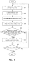
- FIG. 4 is a flowchart of an example process of the travel control according to the embodiment of the present invention.
- road information acquiring section 12a determines the road ahead (step S11), and acquires road information about the road ahead (step S12). Then, vehicle information acquiring section 12b acquires information about the vehicle state (step S13).
- speed estimating section 12c estimates the transition of the vehicle speed of vehicle 1 in a predetermined section of the case where vehicle 1 travels with the maximum accelerator opening (step S14).
- accelerator control section 12d determines whether the maximum value of the vehicle speed estimated by speed estimating section 12c is smaller than upper limit target vehicle speed Vb' and the minimum value of the speed estimated by speed estimating section 12c is smaller than target vehicle speed V' (step S15).
- accelerator control section 12d controls the accelerator opening to maximize the accelerator opening at the present position of the vehicle, that is, at a positon on the flat road (step S16).
- accelerator control section 12d determines whether to complete the accelerator control (step S17).
- accelerator control section 12d determines that this transmission control is to be completed when the driver has requested completion of the automatic travel. Accelerator control section 12d determines that the accelerator control is not to be completed when the transmission gear is switched during the travel.
- accelerator control section 12d determines that the accelerator control is to be completed (YES at step S17)
- control section 12d completes the accelerator control.
- accelerator control section 12d determines that the accelerator control is not to be completed (NO at step S17)
- the processes subsequent to step S11 are again performed.
- speed estimating section 12c estimates the transition of the vehicle speed of the case where vehicle 1 travels in a predetermined section of the road ahead with the present transmission gear and the maximum accelerator opening in the embodiment of the present invention described above, the present invention is not limited to this.
- speed estimating section 12c may estimate the transition of the vehicle speed of the case where the vehicle travels with an accelerator opening equal to or greater than the present accelerator opening, not the maximum accelerator opening.
- accelerator control section 12d operates to maximize the accelerator opening at the present position of the vehicle, that is, at a positon on the flat road.
- condition where the maximum value of the vehicle speed is smaller than upper limit target vehicle speed Vb' may not be taken into consideration.
- road information acquiring section 12a acquires information of a road in a predetermined section ahead of the vehicle that travels with an accelerator opening of a first opening
- vehicle information acquiring section 12b acquires information of the vehicle
- speed estimating section 12c estimates based on the information of the road and the information of the vehicle a transition of a vehicle speed in the predetermined section of a case where the vehicle travels with the accelerator opening of a second opening that is greater than the first opening
- accelerator control section 12d sets the accelerator opening of the vehicle to the second opening when a minimum value of the vehicle speed estimated by speed estimating section 12c is smaller than the target speed.
- the vehicle can go up the upslope road without degrading the fuel economy, and the period until the vehicle reaches the crest can be shortened while avoiding an unnecessary downshift.
- accelerator control section 12d controls the accelerator opening such that of the accelerator opening of vehicle 1 is set to the second opening when the maximum value of the vehicle speed estimated by speed estimating section 12c is smaller than a predetermined upper limit and the minimum value of the vehicle speed estimated by speed estimating section 12c is smaller than a target speed.
- the second opening is a maximized opening.
- road information acquiring section 12a determines the predetermined section in accordance with the present speed of the vehicle.
- the predetermined section for the vehicle speed estimation can be further appropriately changed.
- the present invention is applicable to a travel control device and a travel control method for controlling a travel of the vehicle such that the vehicle speed is set to a target speed.
Landscapes
- Engineering & Computer Science (AREA)
- Transportation (AREA)
- Mechanical Engineering (AREA)
- Automation & Control Theory (AREA)
- Physics & Mathematics (AREA)
- Mathematical Physics (AREA)
- Combustion & Propulsion (AREA)
- Chemical & Material Sciences (AREA)
- Human Computer Interaction (AREA)
- General Physics & Mathematics (AREA)
- Multimedia (AREA)
- Theoretical Computer Science (AREA)
- Control Of Driving Devices And Active Controlling Of Vehicle (AREA)
- Control Of Transmission Device (AREA)
- Control Of Vehicle Engines Or Engines For Specific Uses (AREA)
- Controls For Constant Speed Travelling (AREA)
Abstract
Description
- The present invention relates to a travel control device and a travel control method for controlling a travel of a vehicle such that the vehicle speed is set to a target speed.
- Conventionally, auto-cruising techniques to maintain the speed (vehicle speed) of a vehicle such as an automobile at a target speed have been developed. For example,
PTL 1 discloses an auto-cruising control device that prevents the vehicle speed from being varied at the time when the vehicle travels from a level ground into a slope so as not to make the passenger uncomfortable. - To be more specific, this auto-cruising control device images the forward area in the travelling direction of the vehicle with an imaging device, and detects the road grade from the obtained image. Then, the auto-cruising control device calculates a fuel injection amount which does not cause the variation of the vehicle speed from the road grade and the target speed, and drives the engine at that fuel injection amount from a position before the slope.
-
PTL 1
Japanese Patent Application Laid-Open No.2010-234987 - However, the above-described conventional technique disclosed in
PTL 1 detects the road grade based on the image imaged with the imaging device, and therefore, in the case of a road including an upslope, a downslope and another upslope in this order, the road grade cannot be easily detected. As a result, there is a risk that the fuel injection amount is not appropriately calculated and the fuel economy is degraded. - To solve the above-mentioned problems, an object of the present invention is to provide a travel control device and a travel control method which can control the vehicle to go up an upslope road without degrading the fuel economy, and can shorten the period until the vehicle reaches the crest while avoiding an unnecessary downshift even in the case where the vehicle travels on an upslope road in which the road grade changes in a certain section.
- To solve the above-mentioned problems, a travel control device of an embodiment of the present invention controls a travel of a vehicle such that a vehicle speed is set to a target speed, the travel control device including: an road information acquiring section that acquires information of a road in a predetermined section ahead of the vehicle that travels with an accelerator opening of a first opening; a vehicle information acquiring section that acquires information of the vehicle; a speed estimating section that estimates based on the information of the road and the information of the vehicle a transition of a vehicle speed in the predetermined section of a case where the vehicle travels with the accelerator opening of a second opening that is greater than the first opening; and an accelerator control section that sets the accelerator opening of the vehicle to the second opening when a minimum value of a vehicle speed estimated by the speed estimating section is smaller than the target speed.
- A travel control method of an embodiment of the present invention is a method for controlling a travel of a vehicle such that a vehicle speed is set to a target speed, the method including: acquiring information of a road in a predetermined section ahead of the vehicle that travels with an accelerator opening of a first opening; acquiring information of the vehicle; estimating based on the information of the road and the information of the vehicle a transition of a vehicle speed in the predetermined section of a case where the vehicle travels with the accelerator opening of a second opening that is greater than the first opening; and setting the accelerator opening of the vehicle to the second opening when a minimum value of a vehicle speed estimated by the estimating is smaller than the target speed.
- According to the present invention, even in the case where the vehicle travels on an upslope road in which the road grade changes in a certain section, the vehicle can go up the upslope road without degrading the fuel economy, and the period until the vehicle reaches the crest can be shortened while avoiding an unnecessary downshift.
-
-
FIG. 1 is a block diagram illustrating an example configuration of an automatic travel device according to an embodiment of the present invention; -
FIG. 2 is a block diagram illustrating an example configuration of an automatic travel control device illustrated inFIG. 1 ; -
FIG. 3 illustrates an example of a process of determining the necessity to change the accelerator opening according to the embodiment of the present invention; and -
FIG. 4 is a flowchart of an example process of a travel control according to the embodiment of the present invention. - An embodiment of the present invention is described equal to or lower than with reference to the accompanying drawings.
FIG 1 is a block diagram illustrating an example configuration of automatic travel device 2 according to the embodiment of the present invention. In addition,FIG. 2 is a block diagram illustrating an example configuration of automatictravel control device 12 illustrated inFIG. 1 . - It is to be noted that, while
engine 3 is an in-line six-cylinder diesel engine inFIG. 1 , the present invention is applicable also to a gasoline engine, and the arrangement and the number of the cylinders are not limited. In addition, whilevehicle 1 is a large vehicle such as a truck in which a diesel engine is mounted in the following description, the present invention is not limited to large vehicles such as trucks. - As illustrated in
FIG. 1 , invehicle 1 in which automatic travel device 2 of the present embodiment is mounted, the power ofengine 3 is transmitted totransmission 5 viaclutch 4, and transmitted fromtransmission 5 todifferential gear 7 through apropeller shaft 6, and further, transmitted fromdifferential gear 7 towheel 9 throughdrive shaft 8. In this manner, the power ofengine 3 is transmitted towheel 9, and thusvehicle 1 travels. - Automatic travel device 2 of the present embodiment controls the output of
engine 3, the connection and disconnection ofclutch 4, and the transmission oftransmission 5 for the automatic travel ofvehicle 1. Automatic travel device 2 includes a plurality of control devices. - To be more specific, automatic travel device 2 includes control engine ECU (engine control unit) 10 that controls the output of
engine 3, power transferring ECU (power transferring control unit) 11 that controls the connection and disconnection ofclutch 4 and the transmission oftransmission 5, and automatictravel control device 12 that controls the automatic travel ofvehicle 1. - Each of
engine ECU 10,power transferring ECU 11, and automatictravel control device 12 is composed of a micro controller. Engine ECU 10,power transferring ECU 11, and automatictravel control device 12 are connected with one another with an in-vehicle network, and required data and control signals are exchanged therebetween. - In addition, automatic travel device 2 includes, at a dashboard of a driver's seat not illustrated, target-vehicle
speed setting device 13 and increment/reductionvalue setting device 14, and target-vehiclespeed setting device 13 and increment/reductionvalue setting device 14 are connected with automatictravel control device 12. - Target-vehicle
speed setting device 13 is a device that is manually operated by the driver before the automatic travel ofvehicle 1 is started, to set target-vehicle speed V' [km/h] ofvehicle 1 in the automatic travel. When target-vehicle speed V' is set in target-vehiclespeed setting device 13 by the driver, the target-vehicle speed V' is transmitted to automatictravel control device 12, and stored in a storage device of automatictravel control device 12. - Increment/reduction
value setting device 14 is a device that is operated by the driver before the automatic travel ofvehicle 1 is started and after target-vehicle speed V' is set, to set both speed reduction value -va [km/h] and speed increment value +vb [km/h] ofvehicle 1 in the automatic travel. - When both speed reduction value -va and speed increment value +vb are set in increment/reduction
value setting device 14 by the driver, speed reduction value -va and speed increment value +vb are transmitted to automatictravel control device 12, and stored in a storage device of automatictravel control device 12. - In addition, automatic
travel control device 12 adds speed reduction value -va and speed increment value +vb to target-vehicle speed V' to calculate lower limit target-vehicle speed Va' [km/h] and upper limit target-vehicle speed Vb' [km/h], and stores the calculated values in the storage device of automatictravel control device 12. - For example, in the case where target-vehicle speed V' is 80 km/h, speed reduction value -va is -5 km/h, and speed increment value +vb is +10 km/h, lower limit target-vehicle speed Va' is 75 km/h and upper limit target-vehicle speed Vb' is 90 km/h. It is to be noted that speed reduction value -va and speed increment value +vb may be set to zero.
- Lower limit target-vehicle speed Va' and upper limit target-vehicle speed Vb' define a range of vehicle speed V [km/h] which can be accepted by the driver in the automatic travel of
vehicle 1. - In addition, road
information acquiring device 20 is a device for acquiring road information about the road ahead. The road ahead is the road extending from the present position of the vehicle in the travelling direction of the vehicle. - For example, road
information acquiring device 20 includes presentposition acquiring device 21 that is a receiver of a global positioning system (GPS), andperiphery sensor 22 that detects the distance from vehicles around the travelling vehicle such as a vehicle travelling ahead and/or a vehicle travelling on a side, and the difference in vehicle speed from other vehicles around the travelling vehicle. - Vehicle
information acquiring device 30 is a device for acquiring vehicle information ofvehicle 1. For example, vehicleinformation acquiring device 30 includesaccelerator sensor 31 that detects the pressing amount of the accelerator pedal,brake switch 32 that detects the presence/absence of the pressing of the brake pedal,shift lever 33, turn-signal switch 34, andvehicle speed sensor 35 that detects vehicle speed V ofvehicle 1. In addition,engine ECU 10 andpower transferring ECU 11 are also included in vehicleinformation acquiring device 30. - Braking
device 40 is a device for applying a braking force tovehicle 1.Braking device 40 includesfoot brake 41, retarder 42, andauxiliary brake 43 such as an exhaust brake that is controlled withengine ECU 10 and/orpower transferring ECU 11. - As illustrated in
FIG. 2 , automatictravel control device 12 includes roadinformation acquiring section 12a, vehicleinformation acquiring section 12b,speed estimating section 12c, andaccelerator control section 12d. - Road
information acquiring section 12a acquires road information in a predetermined section ahead of the present point ofvehicle 1. - To be more specific, road
information acquiring section 12a determines the road ahead based on the present position acquired by presentposition acquiring device 21, map data stored in advance and the like, and acquires information about the road grade in a predetermined section of the acquired road ahead, the curve in the predetermined section of the road ahead, the presence/absence of traffic lights and the like. In addition, roadinformation acquiring section 12a acquires information about the distance and the difference in vehicle speed from other travelling vehicles around the vehicle and the like, which is detected byperiphery sensor 22. - It is to be noted that road
information acquiring section 12a may determine the predetermined section in accordance with the speed ofvehicle 1. For example, roadinformation acquiring section 12a may calculate a distance based on the product of the present vehicle speed and a predetermined time, and may set, as the predetermined section, a section corresponding to the distance from the present point ofvehicle 1 in the road ahead. - Vehicle
information acquiring section 12b acquires vehicle information required for the automatic travel ofvehicle 1. - To be more specific, vehicle
information acquiring section 12b acquires information about the pressing amount of the accelerator pedal detected byaccelerator sensor 31, the presence/absence of the pressing of the brake pedal detected bybrake switch 32, the operation ofshift lever 33 and/or turn-signal switch 34, vehicle speed V ofvehicle 1 detected byvehicle speed sensor 35, the output ofengine 3 used inengine ECU 10 andpower transferring ECU 11, the weight ofvehicle 1, the transmission gear oftransmission 5 and the like. - It is to be noted that the information acquired by road
information acquiring section 12a and vehicleinformation acquiring section 12b is not limited to the above-mentioned information, and other information required for the automatic travel ofvehicle 1 may be acquired. In addition, the devices provided in roadinformation acquiring device 20 and/or vehicleinformation acquiring device 30 may be changed or additionally provided in accordance with the information to be acquired. - On the basis of the road information and the vehicle information,
speed estimating section 12c estimates a transition of the speed ofvehicle 1 in a predetermined section of the case wherevehicle 1 travels with the maximum accelerator opening. The method of estimating the vehicle speed withspeed estimating section 12c is described in detail later. -
Accelerator control section 12d controls the accelerator to maximize the accelerator opening of thevehicle 1 when the maximum value of the vehicle speed in the predetermined section estimated byspeed estimating section 12c is smaller than upper limit target vehicle speed Vb' and the minimum value of the speed estimated byspeed estimating section 12c is smaller than target vehicle speed V'. Upper limit target vehicle speed Vb' and target vehicle speed V', which are vehicle speeds set by the driver, are obtained as vehicle information. - In this manner, by maximizing the accelerator opening at the time point when the speed is determined to be smaller than target vehicle speed V', the vehicle speed can be increased at an early stage, and an unnecessary downshift at an upslope road can be suppressed. As a result, fuel economy can be improved, and moreover the period until the vehicle reaches the crest can be shortened.
- In addition, by maximizing the accelerator opening when the maximum value of the estimated vehicle speed is smaller than upper limit target vehicle speed Vb', it is possible to control
vehicle 1 to go up an upslope road at a vehicle speed equal to or lower than the upper limit speed. - Further, by maximizing the accelerator opening, an unnecessary downshift at an upslope road can be further suppressed. As a result, fuel economy can be further improved, and the period until the vehicle reaches the crest can be further shortened.
- Next, the method of estimating the vehicle speed with
speed estimating section 12c is described. When the present vehicle speed is represented by Vn [km/h], and the estimated vehicle speed at a position ahead by L [m] is represented by Vn+1 [km/h], the relationship between Vn and Vn+1 is expressed by the Expression (1).
[Expression 1]
- Here, ΔVn [km/h] is calculated with the Expression (2).
[Expression 2]
- Here, 0[%] is an average road grade from the present position to a position ahead of the present position by L. The average road grade is calculated from the above-described map data.
- In addition, G [km/h2] is the acceleration of the case where the vehicle travels with the present transmission gear and the maximum accelerator opening, and is calculated with the Expression (3).
[Expression 3]
- Here, tq [kgf·m] is the maximum torque of
engine 3 of the case where the vehicle travels with the present transmission gear at vehicle speed Vn, rt the gear ratio of the present transmission gear, rf the gear ratio of the final gear, η the transmission efficiency, tr [m] the tire radius, M [kg] the vehicle weight, rrc the roll resistance coefficient, and arc [kgf/(km/h)2] the air resistance coefficient. These pieces of information are included in the vehicle information that is acquired by vehicleinformation acquiring section 12b. - By use of Expressions (1) to (3),
speed estimating section 12c can estimate vehicle speed Vm of a position ahead of the present position by mL (m=1, 2, · · · ) with the present vehicle speed Vm as the initial value. - Next, an example process of determining the necessity to change the accelerator opening according to the embodiment of the present invention is described.
FIG. 3 illustrates an example of the process of determining the necessity to change the accelerator opening according to the embodiment of the present invention. -
FIG. 3 illustratesvehicle 1 travelling on a flat road, and vehicle 1' travelling on an upslope road ahead thereof by 5L. In addition, the graph ofFIG. 3 shows a transition of an estimated vehicle speed. - In the case of
FIG. 3 , the maximum value of estimated speed V1 is smaller than upper limit target vehicle speed Vb' and minimum value of estimated speed Vs is smaller than target vehicle speed V'. In this case,accelerator control section 12d determines that the accelerator opening should be maximized, and operates to maximize the accelerator opening at the present position of the vehicle, that is, at a positon on the flat road. - Next, an example process of the travel control according to the embodiment of the present invention is described.
FIG. 4 is a flowchart of an example process of the travel control according to the embodiment of the present invention. - First, road
information acquiring section 12a determines the road ahead (step S11), and acquires road information about the road ahead (step S12). Then, vehicleinformation acquiring section 12b acquires information about the vehicle state (step S13). - Subsequently, on the basis of the road information and the vehicle information,
speed estimating section 12c estimates the transition of the vehicle speed ofvehicle 1 in a predetermined section of the case wherevehicle 1 travels with the maximum accelerator opening (step S14). - Next,
accelerator control section 12d determines whether the maximum value of the vehicle speed estimated byspeed estimating section 12c is smaller than upper limit target vehicle speed Vb' and the minimum value of the speed estimated byspeed estimating section 12c is smaller than target vehicle speed V' (step S15). - Then, when the maximum value of the estimated vehicle speed is smaller than upper limit target vehicle speed Vb' and the minimum value of the estimated vehicle speed is smaller than target vehicle speed V' (YES at step S15),
accelerator control section 12d controls the accelerator opening to maximize the accelerator opening at the present position of the vehicle, that is, at a positon on the flat road (step S16). - After step S16, or when a condition where the maximum value of the estimated vehicle speed is smaller than upper limit target vehicle speed Vb' and the minimum value of the estimated vehicle speed is smaller than target vehicle speed V' is not satisfied at step S15 (NO at step S15),
accelerator control section 12d determines whether to complete the accelerator control (step S17). - For example,
accelerator control section 12d determines that this transmission control is to be completed when the driver has requested completion of the automatic travel.Accelerator control section 12d determines that the accelerator control is not to be completed when the transmission gear is switched during the travel. - When
accelerator control section 12d determines that the accelerator control is to be completed (YES at step S17),control section 12d completes the accelerator control. Whenaccelerator control section 12d determines that the accelerator control is not to be completed (NO at step S17), the processes subsequent to step S11 are again performed. - While
speed estimating section 12c estimates the transition of the vehicle speed of the case wherevehicle 1 travels in a predetermined section of the road ahead with the present transmission gear and the maximum accelerator opening in the embodiment of the present invention described above, the present invention is not limited to this. - For example,
speed estimating section 12c may estimate the transition of the vehicle speed of the case where the vehicle travels with an accelerator opening equal to or greater than the present accelerator opening, not the maximum accelerator opening. - Also in this case, when the maximum value of the vehicle speed estimated by
speed estimating section 12c is smaller than upper limit target vehicle speed Vb' and the minimum value of the speed estimated byspeed estimating section 12c is smaller than target vehicle speed V',accelerator control section 12d operates to maximize the accelerator opening at the present position of the vehicle, that is, at a positon on the flat road. - In addition, the condition where the maximum value of the vehicle speed is smaller than upper limit target vehicle speed Vb' may not be taken into consideration.
- As described above, according to the present embodiment, in
travel control device 12 that controls a travel of a vehicle such that a vehicle speed is set to a target speed, roadinformation acquiring section 12a acquires information of a road in a predetermined section ahead of the vehicle that travels with an accelerator opening of a first opening; vehicleinformation acquiring section 12b acquires information of the vehicle;speed estimating section 12c estimates based on the information of the road and the information of the vehicle a transition of a vehicle speed in the predetermined section of a case where the vehicle travels with the accelerator opening of a second opening that is greater than the first opening; andaccelerator control section 12d sets the accelerator opening of the vehicle to the second opening when a minimum value of the vehicle speed estimated byspeed estimating section 12c is smaller than the target speed. With this configuration, even in the case where the vehicle travels on an upslope road in which the road grade changes in a certain section, the vehicle can go up the upslope road without degrading the fuel economy, and the period until the vehicle reaches the crest can be shortened while avoiding an unnecessary downshift. - In addition, according to the present embodiment,
accelerator control section 12d controls the accelerator opening such that of the accelerator opening ofvehicle 1 is set to the second opening when the maximum value of the vehicle speed estimated byspeed estimating section 12c is smaller than a predetermined upper limit and the minimum value of the vehicle speed estimated byspeed estimating section 12c is smaller than a target speed. With this configuration, it is possible to controlvehicle 1 to go up an upslope road at a vehicle speed equal to or lower than the upper limit speed. - In addition, in the present embodiment, the second opening is a maximized opening. With this configuration, an unnecessary downshift at an upslope road can be further suppressed, fuel economy can be further improved, and the period until the vehicle reaches the crest can be further shortened.
- In addition, in the present embodiment, road
information acquiring section 12a determines the predetermined section in accordance with the present speed of the vehicle. With this configuration, the predetermined section for the vehicle speed estimation can be further appropriately changed. - This application is entitled to and claims the benefit of Japanese Patent Application No.
2015-064244 dated March 26, 2015 - The present invention is applicable to a travel control device and a travel control method for controlling a travel of the vehicle such that the vehicle speed is set to a target speed.
-
- 1 Vehicle
- 2 Automatic travel device
- 3 Engine
- 4 Clutch
- 5 Transmission
- 10 Engine ECU (engine control unit)
- 11 Power transferring ECU (power transferring control unit)
- 12 Automatic travel control device
- 12a Road information acquiring section
- 12b Vehicle information acquiring section
- 12c Speed estimating section
- 12d Accelerator control section
- 13 Target-vehicle speed setting device
- 14 Increment/reduction value setting device
- 20 Road information acquiring device
- 30 Vehicle information acquiring device
- 40 Braking device
Claims (6)
- A travel control device that controls a travel of a vehicle such that a vehicle speed is set to a target speed, the travel control device comprising:a road information acquiring section that acquires information of a road in a predetermined section ahead of the vehicle that travels with an accelerator opening of a first opening;a vehicle information acquiring section that acquires information of the vehicle;a speed estimating section that estimates, based on the information of the road and the information of the vehicle, a transition of a vehicle speed in the predetermined section of a case where the vehicle travels with the accelerator opening of a second opening that is greater than the first opening; andan accelerator control section that sets the accelerator opening of the vehicle to the second opening when a minimum value of the transition of the vehicle speed estimated by the speed estimating section is smaller than the target speed.
- The travel control device according to claim 1, wherein the accelerator control section sets the accelerator opening of the vehicle to the second opening when a maximum value of the transition of the vehicle speed estimated by the speed estimating section is smaller than a predetermined upper limit and the minimum value of the transition of the vehicle speed estimated by the speed estimating section is smaller than the target speed.
- The travel control device according to claim 1, wherein the second opening is a maximized opening.
- The travel control device according to claim 1, wherein the road information acquiring section determines the predetermined section in accordance with a present speed of the vehicle.
- The travel control device according to claim 1, wherein when a downshift is performed in the vehicle, the vehicle information acquiring section again acquires the information of the vehicle, and the speed estimating section again estimates the transition of the vehicle speed.
- A travel control method for controlling a travel of a vehicle such that a vehicle speed is set to a target speed, the method comprising:acquiring information of a road in a predetermined section ahead of the vehicle that travels with an accelerator opening of a first opening;acquiring information of the vehicle;estimating, based on the information of the road and the information of the vehicle, a transition of a vehicle speed in the predetermined section of a case where the vehicle travels with the accelerator opening of a second opening that is greater than the first opening; andsetting the accelerator opening of the vehicle to the second opening when a minimum value of the transition of the vehicle speed estimated by the estimating is smaller than the target speed.
Applications Claiming Priority (2)
| Application Number | Priority Date | Filing Date | Title |
|---|---|---|---|
| JP2015064244A JP2016182887A (en) | 2015-03-26 | 2015-03-26 | Travel control device and travel control method |
| PCT/JP2016/058629 WO2016152750A1 (en) | 2015-03-26 | 2016-03-18 | Cruise control device and cruise control method |
Publications (3)
| Publication Number | Publication Date |
|---|---|
| EP3275715A1 true EP3275715A1 (en) | 2018-01-31 |
| EP3275715A4 EP3275715A4 (en) | 2018-05-09 |
| EP3275715B1 EP3275715B1 (en) | 2022-05-04 |
Family
ID=56978531
Family Applications (1)
| Application Number | Title | Priority Date | Filing Date |
|---|---|---|---|
| EP16768653.4A Active EP3275715B1 (en) | 2015-03-26 | 2016-03-18 | Cruise control device and cruise control method |
Country Status (5)
| Country | Link |
|---|---|
| US (1) | US20180118207A1 (en) |
| EP (1) | EP3275715B1 (en) |
| JP (1) | JP2016182887A (en) |
| CN (1) | CN107428248A (en) |
| WO (1) | WO2016152750A1 (en) |
Families Citing this family (11)
| Publication number | Priority date | Publication date | Assignee | Title |
|---|---|---|---|---|
| JP6485157B2 (en) * | 2015-03-26 | 2019-03-20 | いすゞ自動車株式会社 | Travel control device and travel control method |
| CN108068806B (en) * | 2016-11-11 | 2020-06-26 | 郑州宇通客车股份有限公司 | Cruise energy-saving control method and device for automobile engine |
| JP6455499B2 (en) | 2016-11-25 | 2019-01-23 | トヨタ自動車株式会社 | Vehicle control device |
| KR20180080933A (en) * | 2017-01-05 | 2018-07-13 | 박향숙 | Apparatus and method for controlling self drive of vehicle using elevation |
| KR20180112949A (en) | 2017-04-05 | 2018-10-15 | 현대자동차주식회사 | Autonomous Travelling Control Ststem And Control Metheod Using It |
| CN107512266A (en) * | 2017-08-01 | 2017-12-26 | 北京理工大学 | A kind of operating mode Forecasting Methodology of the hybrid car travel operating mode based on waveform training |
| JP7206600B2 (en) * | 2018-03-07 | 2023-01-18 | いすゞ自動車株式会社 | Driving control device and vehicle |
| DE102018220808A1 (en) * | 2018-12-03 | 2020-06-04 | Audi Ag | Method for predicting a future value of at least one kinematic parameter of a vehicle |
| WO2022138778A1 (en) * | 2020-12-24 | 2022-06-30 | 大学共同利用機関法人情報・システム研究機構 | Monitoring device and monitoring method |
| CN113353088B (en) * | 2021-07-16 | 2023-03-10 | 苏州智加科技有限公司 | Vehicle running speed control method, device, control equipment and storage medium |
| JP7661931B2 (en) * | 2022-05-30 | 2025-04-15 | トヨタ自動車株式会社 | Vehicle control device |
Family Cites Families (25)
| Publication number | Priority date | Publication date | Assignee | Title |
|---|---|---|---|---|
| JPS6261831A (en) * | 1985-09-11 | 1987-03-18 | Mazda Motor Corp | Constant speed running device for vehicle |
| JP3203976B2 (en) * | 1994-09-05 | 2001-09-04 | 日産自動車株式会社 | Vehicle driving force control device |
| US5854987A (en) * | 1995-02-22 | 1998-12-29 | Honda Giken Kogyo Kabushiki Kaisha | Vehicle steering control system using navigation system |
| JPH1035322A (en) * | 1996-07-22 | 1998-02-10 | Nissan Motor Co Ltd | Vehicle speed control device for vehicles |
| JP3681052B2 (en) * | 2000-01-11 | 2005-08-10 | 三菱電機株式会社 | Follow-up control device |
| JP4290635B2 (en) * | 2004-11-10 | 2009-07-08 | 本田技研工業株式会社 | Vehicle travel safety device having a constant speed travel control device |
| JP4796400B2 (en) * | 2006-02-01 | 2011-10-19 | クラリオン株式会社 | Vehicle speed control device, target speed setting method and program in the same |
| JP4807107B2 (en) * | 2006-03-02 | 2011-11-02 | 日産自動車株式会社 | Vehicle travel control device |
| US20070265759A1 (en) * | 2006-05-09 | 2007-11-15 | David Salinas | Method and system for utilizing topographical awareness in an adaptive cruise control |
| JP2008056226A (en) * | 2006-08-01 | 2008-03-13 | Nissan Motor Co Ltd | Vehicle travel control device and vehicle travel control method |
| US20100332100A1 (en) * | 2008-08-06 | 2010-12-30 | Ronald David Faggetter | Land vehicle cruise control |
| US8700256B2 (en) * | 2008-08-22 | 2014-04-15 | Daimler Trucks North America Llc | Vehicle disturbance estimator and method |
| JP2010132241A (en) * | 2008-12-08 | 2010-06-17 | Aisin Aw Co Ltd | Traveling support device, traveling support method, and computer program |
| US8359149B2 (en) * | 2009-02-03 | 2013-01-22 | GM Global Technology Operations LLC | Method for integrating multiple feature adaptive cruise control |
| SE534038C2 (en) * | 2009-06-10 | 2011-04-12 | Scania Cv Ab | Method and module for controlling the speed of a vehicle |
| JP5434464B2 (en) * | 2009-10-19 | 2014-03-05 | アイシン・エィ・ダブリュ株式会社 | Driving support apparatus, method and program |
| US9020726B2 (en) * | 2009-11-04 | 2015-04-28 | Daimler Trucks North America Llc | Vehicle torque management |
| US20110276216A1 (en) * | 2010-05-07 | 2011-11-10 | Texas Instruments Incorporated | Automotive cruise controls, circuits, systems and processes |
| JP5127917B2 (en) * | 2010-12-13 | 2013-01-23 | 日立オートモティブシステムズ株式会社 | Vehicle control device |
| US8757092B2 (en) * | 2011-03-22 | 2014-06-24 | Eco-Composites Llc | Animal bedding and associated method for preparing the same |
| SE536399C2 (en) * | 2011-05-16 | 2013-10-08 | Scania Cv Ab | Driver interaction at reference speed regulating cruise control |
| SE536268C2 (en) * | 2011-12-22 | 2013-07-23 | Scania Cv Ab | A module and a method for mode selection when determining reference values |
| WO2013137387A1 (en) * | 2012-03-15 | 2013-09-19 | 日産自動車株式会社 | Vehicle output control device |
| JP6331295B2 (en) * | 2013-09-05 | 2018-05-30 | いすゞ自動車株式会社 | Automatic traveling device for vehicle, vehicle, and automatic traveling method for vehicle |
| JP6677152B2 (en) * | 2016-12-22 | 2020-04-08 | 株式会社豊田自動織機 | Pollution degree estimation device |
-
2015
- 2015-03-26 JP JP2015064244A patent/JP2016182887A/en active Pending
-
2016
- 2016-03-03 US US15/561,257 patent/US20180118207A1/en not_active Abandoned
- 2016-03-18 EP EP16768653.4A patent/EP3275715B1/en active Active
- 2016-03-18 CN CN201680018396.XA patent/CN107428248A/en not_active Withdrawn
- 2016-03-18 WO PCT/JP2016/058629 patent/WO2016152750A1/en not_active Ceased
Also Published As
| Publication number | Publication date |
|---|---|
| US20180118207A1 (en) | 2018-05-03 |
| CN107428248A (en) | 2017-12-01 |
| EP3275715B1 (en) | 2022-05-04 |
| WO2016152750A1 (en) | 2016-09-29 |
| EP3275715A4 (en) | 2018-05-09 |
| JP2016182887A (en) | 2016-10-20 |
Similar Documents
| Publication | Publication Date | Title |
|---|---|---|
| EP3275715B1 (en) | Cruise control device and cruise control method | |
| EP3276222A1 (en) | Travel control device, and travel control method | |
| US10428937B2 (en) | Cruise control device and cruise control method | |
| US10369996B2 (en) | Travel control device and travel control method | |
| US10486710B2 (en) | Cruise control device and cruise control method | |
| CN106467107A (en) | The method controlling vehicle | |
| CN110431058B (en) | Travel control device, vehicle, and travel control method | |
| EP3275756B1 (en) | Travel control device and travel control method | |
| CN115003578A (en) | Cruise control system and method for controlling a powertrain | |
| US20200231180A1 (en) | Travel control device and travel control method | |
| JP2011214408A (en) | Power train control device for vehicle | |
| CN110015299A (en) | Method for running the driving system of motor vehicle | |
| US12576847B2 (en) | Method and control arrangement for controlling a vehicle during a downhill start | |
| CN112677952B (en) | Intelligent driving control method and system | |
| JP2011214407A (en) | Power train control device for vehicle | |
| US20210009132A1 (en) | Travel control device and travel control method | |
| JP2011214410A (en) | Power train control device for vehicle | |
| JP2021081343A (en) | Vehicle hydraulic oil evaluation device |
Legal Events
| Date | Code | Title | Description |
|---|---|---|---|
| STAA | Information on the status of an ep patent application or granted ep patent |
Free format text: STATUS: THE INTERNATIONAL PUBLICATION HAS BEEN MADE |
|
| PUAI | Public reference made under article 153(3) epc to a published international application that has entered the european phase |
Free format text: ORIGINAL CODE: 0009012 |
|
| STAA | Information on the status of an ep patent application or granted ep patent |
Free format text: STATUS: REQUEST FOR EXAMINATION WAS MADE |
|
| 17P | Request for examination filed |
Effective date: 20170919 |
|
| AK | Designated contracting states |
Kind code of ref document: A1 Designated state(s): AL AT BE BG CH CY CZ DE DK EE ES FI FR GB GR HR HU IE IS IT LI LT LU LV MC MK MT NL NO PL PT RO RS SE SI SK SM TR |
|
| AX | Request for extension of the european patent |
Extension state: BA ME |
|
| A4 | Supplementary search report drawn up and despatched |
Effective date: 20180410 |
|
| RIC1 | Information provided on ipc code assigned before grant |
Ipc: B60W 40/105 20120101ALI20180404BHEP Ipc: B60W 50/00 20060101ALI20180404BHEP Ipc: B60W 30/14 20060101ALI20180404BHEP Ipc: B60K 31/00 20060101AFI20180404BHEP |
|
| DAV | Request for validation of the european patent (deleted) | ||
| DAX | Request for extension of the european patent (deleted) | ||
| GRAP | Despatch of communication of intention to grant a patent |
Free format text: ORIGINAL CODE: EPIDOSNIGR1 |
|
| STAA | Information on the status of an ep patent application or granted ep patent |
Free format text: STATUS: GRANT OF PATENT IS INTENDED |
|
| INTG | Intention to grant announced |
Effective date: 20211116 |
|
| GRAS | Grant fee paid |
Free format text: ORIGINAL CODE: EPIDOSNIGR3 |
|
| GRAA | (expected) grant |
Free format text: ORIGINAL CODE: 0009210 |
|
| STAA | Information on the status of an ep patent application or granted ep patent |
Free format text: STATUS: THE PATENT HAS BEEN GRANTED |
|
| AK | Designated contracting states |
Kind code of ref document: B1 Designated state(s): AL AT BE BG CH CY CZ DE DK EE ES FI FR GB GR HR HU IE IS IT LI LT LU LV MC MK MT NL NO PL PT RO RS SE SI SK SM TR |
|
| REG | Reference to a national code |
Ref country code: GB Ref legal event code: FG4D |
|
| REG | Reference to a national code |
Ref country code: CH Ref legal event code: EP |
|
| REG | Reference to a national code |
Ref country code: AT Ref legal event code: REF Ref document number: 1488691 Country of ref document: AT Kind code of ref document: T Effective date: 20220515 |
|
| REG | Reference to a national code |
Ref country code: DE Ref legal event code: R096 Ref document number: 602016071791 Country of ref document: DE |
|
| REG | Reference to a national code |
Ref country code: IE Ref legal event code: FG4D |
|
| REG | Reference to a national code |
Ref country code: LT Ref legal event code: MG9D |
|
| REG | Reference to a national code |
Ref country code: NL Ref legal event code: MP Effective date: 20220504 |
|
| REG | Reference to a national code |
Ref country code: AT Ref legal event code: MK05 Ref document number: 1488691 Country of ref document: AT Kind code of ref document: T Effective date: 20220504 |
|
| PG25 | Lapsed in a contracting state [announced via postgrant information from national office to epo] |
Ref country code: SE Free format text: LAPSE BECAUSE OF FAILURE TO SUBMIT A TRANSLATION OF THE DESCRIPTION OR TO PAY THE FEE WITHIN THE PRESCRIBED TIME-LIMIT Effective date: 20220504 Ref country code: PT Free format text: LAPSE BECAUSE OF FAILURE TO SUBMIT A TRANSLATION OF THE DESCRIPTION OR TO PAY THE FEE WITHIN THE PRESCRIBED TIME-LIMIT Effective date: 20220905 Ref country code: NO Free format text: LAPSE BECAUSE OF FAILURE TO SUBMIT A TRANSLATION OF THE DESCRIPTION OR TO PAY THE FEE WITHIN THE PRESCRIBED TIME-LIMIT Effective date: 20220804 Ref country code: NL Free format text: LAPSE BECAUSE OF FAILURE TO SUBMIT A TRANSLATION OF THE DESCRIPTION OR TO PAY THE FEE WITHIN THE PRESCRIBED TIME-LIMIT Effective date: 20220504 Ref country code: LT Free format text: LAPSE BECAUSE OF FAILURE TO SUBMIT A TRANSLATION OF THE DESCRIPTION OR TO PAY THE FEE WITHIN THE PRESCRIBED TIME-LIMIT Effective date: 20220504 Ref country code: HR Free format text: LAPSE BECAUSE OF FAILURE TO SUBMIT A TRANSLATION OF THE DESCRIPTION OR TO PAY THE FEE WITHIN THE PRESCRIBED TIME-LIMIT Effective date: 20220504 Ref country code: GR Free format text: LAPSE BECAUSE OF FAILURE TO SUBMIT A TRANSLATION OF THE DESCRIPTION OR TO PAY THE FEE WITHIN THE PRESCRIBED TIME-LIMIT Effective date: 20220805 Ref country code: FI Free format text: LAPSE BECAUSE OF FAILURE TO SUBMIT A TRANSLATION OF THE DESCRIPTION OR TO PAY THE FEE WITHIN THE PRESCRIBED TIME-LIMIT Effective date: 20220504 Ref country code: ES Free format text: LAPSE BECAUSE OF FAILURE TO SUBMIT A TRANSLATION OF THE DESCRIPTION OR TO PAY THE FEE WITHIN THE PRESCRIBED TIME-LIMIT Effective date: 20220504 Ref country code: BG Free format text: LAPSE BECAUSE OF FAILURE TO SUBMIT A TRANSLATION OF THE DESCRIPTION OR TO PAY THE FEE WITHIN THE PRESCRIBED TIME-LIMIT Effective date: 20220804 Ref country code: AT Free format text: LAPSE BECAUSE OF FAILURE TO SUBMIT A TRANSLATION OF THE DESCRIPTION OR TO PAY THE FEE WITHIN THE PRESCRIBED TIME-LIMIT Effective date: 20220504 |
|
| PG25 | Lapsed in a contracting state [announced via postgrant information from national office to epo] |
Ref country code: RS Free format text: LAPSE BECAUSE OF FAILURE TO SUBMIT A TRANSLATION OF THE DESCRIPTION OR TO PAY THE FEE WITHIN THE PRESCRIBED TIME-LIMIT Effective date: 20220504 Ref country code: PL Free format text: LAPSE BECAUSE OF FAILURE TO SUBMIT A TRANSLATION OF THE DESCRIPTION OR TO PAY THE FEE WITHIN THE PRESCRIBED TIME-LIMIT Effective date: 20220504 Ref country code: LV Free format text: LAPSE BECAUSE OF FAILURE TO SUBMIT A TRANSLATION OF THE DESCRIPTION OR TO PAY THE FEE WITHIN THE PRESCRIBED TIME-LIMIT Effective date: 20220504 Ref country code: IS Free format text: LAPSE BECAUSE OF FAILURE TO SUBMIT A TRANSLATION OF THE DESCRIPTION OR TO PAY THE FEE WITHIN THE PRESCRIBED TIME-LIMIT Effective date: 20220904 |
|
| PG25 | Lapsed in a contracting state [announced via postgrant information from national office to epo] |
Ref country code: SM Free format text: LAPSE BECAUSE OF FAILURE TO SUBMIT A TRANSLATION OF THE DESCRIPTION OR TO PAY THE FEE WITHIN THE PRESCRIBED TIME-LIMIT Effective date: 20220504 Ref country code: SK Free format text: LAPSE BECAUSE OF FAILURE TO SUBMIT A TRANSLATION OF THE DESCRIPTION OR TO PAY THE FEE WITHIN THE PRESCRIBED TIME-LIMIT Effective date: 20220504 Ref country code: RO Free format text: LAPSE BECAUSE OF FAILURE TO SUBMIT A TRANSLATION OF THE DESCRIPTION OR TO PAY THE FEE WITHIN THE PRESCRIBED TIME-LIMIT Effective date: 20220504 Ref country code: EE Free format text: LAPSE BECAUSE OF FAILURE TO SUBMIT A TRANSLATION OF THE DESCRIPTION OR TO PAY THE FEE WITHIN THE PRESCRIBED TIME-LIMIT Effective date: 20220504 Ref country code: DK Free format text: LAPSE BECAUSE OF FAILURE TO SUBMIT A TRANSLATION OF THE DESCRIPTION OR TO PAY THE FEE WITHIN THE PRESCRIBED TIME-LIMIT Effective date: 20220504 Ref country code: CZ Free format text: LAPSE BECAUSE OF FAILURE TO SUBMIT A TRANSLATION OF THE DESCRIPTION OR TO PAY THE FEE WITHIN THE PRESCRIBED TIME-LIMIT Effective date: 20220504 |
|
| REG | Reference to a national code |
Ref country code: DE Ref legal event code: R097 Ref document number: 602016071791 Country of ref document: DE |
|
| PLBE | No opposition filed within time limit |
Free format text: ORIGINAL CODE: 0009261 |
|
| STAA | Information on the status of an ep patent application or granted ep patent |
Free format text: STATUS: NO OPPOSITION FILED WITHIN TIME LIMIT |
|
| PG25 | Lapsed in a contracting state [announced via postgrant information from national office to epo] |
Ref country code: AL Free format text: LAPSE BECAUSE OF FAILURE TO SUBMIT A TRANSLATION OF THE DESCRIPTION OR TO PAY THE FEE WITHIN THE PRESCRIBED TIME-LIMIT Effective date: 20220504 |
|
| 26N | No opposition filed |
Effective date: 20230207 |
|
| PG25 | Lapsed in a contracting state [announced via postgrant information from national office to epo] |
Ref country code: SI Free format text: LAPSE BECAUSE OF FAILURE TO SUBMIT A TRANSLATION OF THE DESCRIPTION OR TO PAY THE FEE WITHIN THE PRESCRIBED TIME-LIMIT Effective date: 20220504 |
|
| PG25 | Lapsed in a contracting state [announced via postgrant information from national office to epo] |
Ref country code: MC Free format text: LAPSE BECAUSE OF FAILURE TO SUBMIT A TRANSLATION OF THE DESCRIPTION OR TO PAY THE FEE WITHIN THE PRESCRIBED TIME-LIMIT Effective date: 20220504 |
|
| REG | Reference to a national code |
Ref country code: CH Ref legal event code: PL |
|
| GBPC | Gb: european patent ceased through non-payment of renewal fee |
Effective date: 20230318 |
|
| REG | Reference to a national code |
Ref country code: BE Ref legal event code: MM Effective date: 20230331 |
|
| PG25 | Lapsed in a contracting state [announced via postgrant information from national office to epo] |
Ref country code: LU Free format text: LAPSE BECAUSE OF NON-PAYMENT OF DUE FEES Effective date: 20230318 |
|
| REG | Reference to a national code |
Ref country code: IE Ref legal event code: MM4A |
|
| PG25 | Lapsed in a contracting state [announced via postgrant information from national office to epo] |
Ref country code: GB Free format text: LAPSE BECAUSE OF NON-PAYMENT OF DUE FEES Effective date: 20230318 |
|
| PG25 | Lapsed in a contracting state [announced via postgrant information from national office to epo] |
Ref country code: LI Free format text: LAPSE BECAUSE OF NON-PAYMENT OF DUE FEES Effective date: 20230331 Ref country code: IT Free format text: LAPSE BECAUSE OF FAILURE TO SUBMIT A TRANSLATION OF THE DESCRIPTION OR TO PAY THE FEE WITHIN THE PRESCRIBED TIME-LIMIT Effective date: 20220504 Ref country code: IE Free format text: LAPSE BECAUSE OF NON-PAYMENT OF DUE FEES Effective date: 20230318 Ref country code: GB Free format text: LAPSE BECAUSE OF NON-PAYMENT OF DUE FEES Effective date: 20230318 Ref country code: FR Free format text: LAPSE BECAUSE OF NON-PAYMENT OF DUE FEES Effective date: 20230331 Ref country code: CH Free format text: LAPSE BECAUSE OF NON-PAYMENT OF DUE FEES Effective date: 20230331 |
|
| PG25 | Lapsed in a contracting state [announced via postgrant information from national office to epo] |
Ref country code: BE Free format text: LAPSE BECAUSE OF NON-PAYMENT OF DUE FEES Effective date: 20230331 |
|
| PG25 | Lapsed in a contracting state [announced via postgrant information from national office to epo] |
Ref country code: BG Free format text: LAPSE BECAUSE OF FAILURE TO SUBMIT A TRANSLATION OF THE DESCRIPTION OR TO PAY THE FEE WITHIN THE PRESCRIBED TIME-LIMIT Effective date: 20220504 |
|
| PG25 | Lapsed in a contracting state [announced via postgrant information from national office to epo] |
Ref country code: BG Free format text: LAPSE BECAUSE OF FAILURE TO SUBMIT A TRANSLATION OF THE DESCRIPTION OR TO PAY THE FEE WITHIN THE PRESCRIBED TIME-LIMIT Effective date: 20220504 |
|
| PG25 | Lapsed in a contracting state [announced via postgrant information from national office to epo] |
Ref country code: CY Free format text: LAPSE BECAUSE OF FAILURE TO SUBMIT A TRANSLATION OF THE DESCRIPTION OR TO PAY THE FEE WITHIN THE PRESCRIBED TIME-LIMIT; INVALID AB INITIO Effective date: 20160318 |
|
| PG25 | Lapsed in a contracting state [announced via postgrant information from national office to epo] |
Ref country code: HU Free format text: LAPSE BECAUSE OF FAILURE TO SUBMIT A TRANSLATION OF THE DESCRIPTION OR TO PAY THE FEE WITHIN THE PRESCRIBED TIME-LIMIT; INVALID AB INITIO Effective date: 20160318 |
|
| PG25 | Lapsed in a contracting state [announced via postgrant information from national office to epo] |
Ref country code: TR Free format text: LAPSE BECAUSE OF FAILURE TO SUBMIT A TRANSLATION OF THE DESCRIPTION OR TO PAY THE FEE WITHIN THE PRESCRIBED TIME-LIMIT Effective date: 20220504 |
|
| PGFP | Annual fee paid to national office [announced via postgrant information from national office to epo] |
Ref country code: DE Payment date: 20260219 Year of fee payment: 11 |