EP3275411A1 - Optical system for a laser therapy instrument - Google Patents
Optical system for a laser therapy instrument Download PDFInfo
- Publication number
- EP3275411A1 EP3275411A1 EP17167182.9A EP17167182A EP3275411A1 EP 3275411 A1 EP3275411 A1 EP 3275411A1 EP 17167182 A EP17167182 A EP 17167182A EP 3275411 A1 EP3275411 A1 EP 3275411A1
- Authority
- EP
- European Patent Office
- Prior art keywords
- lens
- objective
- cornea
- region
- focus
- Prior art date
- Legal status (The legal status is an assumption and is not a legal conclusion. Google has not performed a legal analysis and makes no representation as to the accuracy of the status listed.)
- Granted
Links
Images
Classifications
-
- A—HUMAN NECESSITIES
- A61—MEDICAL OR VETERINARY SCIENCE; HYGIENE
- A61F—FILTERS IMPLANTABLE INTO BLOOD VESSELS; PROSTHESES; DEVICES PROVIDING PATENCY TO, OR PREVENTING COLLAPSING OF, TUBULAR STRUCTURES OF THE BODY, e.g. STENTS; ORTHOPAEDIC, NURSING OR CONTRACEPTIVE DEVICES; FOMENTATION; TREATMENT OR PROTECTION OF EYES OR EARS; BANDAGES, DRESSINGS OR ABSORBENT PADS; FIRST-AID KITS
- A61F9/00—Methods or devices for treatment of the eyes; Devices for putting in contact-lenses; Devices to correct squinting; Apparatus to guide the blind; Protective devices for the eyes, carried on the body or in the hand
- A61F9/007—Methods or devices for eye surgery
- A61F9/008—Methods or devices for eye surgery using laser
- A61F9/00825—Methods or devices for eye surgery using laser for photodisruption
-
- A—HUMAN NECESSITIES
- A61—MEDICAL OR VETERINARY SCIENCE; HYGIENE
- A61F—FILTERS IMPLANTABLE INTO BLOOD VESSELS; PROSTHESES; DEVICES PROVIDING PATENCY TO, OR PREVENTING COLLAPSING OF, TUBULAR STRUCTURES OF THE BODY, e.g. STENTS; ORTHOPAEDIC, NURSING OR CONTRACEPTIVE DEVICES; FOMENTATION; TREATMENT OR PROTECTION OF EYES OR EARS; BANDAGES, DRESSINGS OR ABSORBENT PADS; FIRST-AID KITS
- A61F9/00—Methods or devices for treatment of the eyes; Devices for putting in contact-lenses; Devices to correct squinting; Apparatus to guide the blind; Protective devices for the eyes, carried on the body or in the hand
- A61F9/007—Methods or devices for eye surgery
- A61F9/008—Methods or devices for eye surgery using laser
-
- A—HUMAN NECESSITIES
- A61—MEDICAL OR VETERINARY SCIENCE; HYGIENE
- A61F—FILTERS IMPLANTABLE INTO BLOOD VESSELS; PROSTHESES; DEVICES PROVIDING PATENCY TO, OR PREVENTING COLLAPSING OF, TUBULAR STRUCTURES OF THE BODY, e.g. STENTS; ORTHOPAEDIC, NURSING OR CONTRACEPTIVE DEVICES; FOMENTATION; TREATMENT OR PROTECTION OF EYES OR EARS; BANDAGES, DRESSINGS OR ABSORBENT PADS; FIRST-AID KITS
- A61F9/00—Methods or devices for treatment of the eyes; Devices for putting in contact-lenses; Devices to correct squinting; Apparatus to guide the blind; Protective devices for the eyes, carried on the body or in the hand
- A61F9/007—Methods or devices for eye surgery
- A61F9/008—Methods or devices for eye surgery using laser
- A61F2009/00861—Methods or devices for eye surgery using laser adapted for treatment at a particular location
- A61F2009/0087—Lens
-
- A—HUMAN NECESSITIES
- A61—MEDICAL OR VETERINARY SCIENCE; HYGIENE
- A61F—FILTERS IMPLANTABLE INTO BLOOD VESSELS; PROSTHESES; DEVICES PROVIDING PATENCY TO, OR PREVENTING COLLAPSING OF, TUBULAR STRUCTURES OF THE BODY, e.g. STENTS; ORTHOPAEDIC, NURSING OR CONTRACEPTIVE DEVICES; FOMENTATION; TREATMENT OR PROTECTION OF EYES OR EARS; BANDAGES, DRESSINGS OR ABSORBENT PADS; FIRST-AID KITS
- A61F9/00—Methods or devices for treatment of the eyes; Devices for putting in contact-lenses; Devices to correct squinting; Apparatus to guide the blind; Protective devices for the eyes, carried on the body or in the hand
- A61F9/007—Methods or devices for eye surgery
- A61F9/008—Methods or devices for eye surgery using laser
- A61F2009/00861—Methods or devices for eye surgery using laser adapted for treatment at a particular location
- A61F2009/00872—Cornea
-
- A—HUMAN NECESSITIES
- A61—MEDICAL OR VETERINARY SCIENCE; HYGIENE
- A61F—FILTERS IMPLANTABLE INTO BLOOD VESSELS; PROSTHESES; DEVICES PROVIDING PATENCY TO, OR PREVENTING COLLAPSING OF, TUBULAR STRUCTURES OF THE BODY, e.g. STENTS; ORTHOPAEDIC, NURSING OR CONTRACEPTIVE DEVICES; FOMENTATION; TREATMENT OR PROTECTION OF EYES OR EARS; BANDAGES, DRESSINGS OR ABSORBENT PADS; FIRST-AID KITS
- A61F9/00—Methods or devices for treatment of the eyes; Devices for putting in contact-lenses; Devices to correct squinting; Apparatus to guide the blind; Protective devices for the eyes, carried on the body or in the hand
- A61F9/007—Methods or devices for eye surgery
- A61F9/008—Methods or devices for eye surgery using laser
- A61F2009/00861—Methods or devices for eye surgery using laser adapted for treatment at a particular location
- A61F2009/00874—Vitreous
-
- A—HUMAN NECESSITIES
- A61—MEDICAL OR VETERINARY SCIENCE; HYGIENE
- A61F—FILTERS IMPLANTABLE INTO BLOOD VESSELS; PROSTHESES; DEVICES PROVIDING PATENCY TO, OR PREVENTING COLLAPSING OF, TUBULAR STRUCTURES OF THE BODY, e.g. STENTS; ORTHOPAEDIC, NURSING OR CONTRACEPTIVE DEVICES; FOMENTATION; TREATMENT OR PROTECTION OF EYES OR EARS; BANDAGES, DRESSINGS OR ABSORBENT PADS; FIRST-AID KITS
- A61F9/00—Methods or devices for treatment of the eyes; Devices for putting in contact-lenses; Devices to correct squinting; Apparatus to guide the blind; Protective devices for the eyes, carried on the body or in the hand
- A61F9/007—Methods or devices for eye surgery
- A61F9/008—Methods or devices for eye surgery using laser
- A61F9/00825—Methods or devices for eye surgery using laser for photodisruption
- A61F9/0084—Laser features or special beam parameters therefor
Definitions
- the present invention relates to an optical system for a laser therapy instrument for the application of laser radiation on and in the eye, suited particularly for laser surgery of the cornea and/or of the crystalline lens.
- Laser therapy instruments are used, e.g., for correcting an ametropia of the human eye by a laser-surgical operation of the cornea.
- a lid is formed on the outer surface of the cornea, which lid is attached along one edge and is therefore known as a flap, and the thickness of which is substantially smaller then the thickness of the cornea.
- this flap is folded back, and from the surface of the region of the cornea that is now exposed, tissue is removed thereupon by means of a laser beam pulsed in the femtosecond range, in order to change the curvature of the cornea.
- a laser beam pulsed in the femtosecond range in order to change the curvature of the cornea.
- a laser system described in DE 10 2008 027 358 A1 is intended for the analysis and treatment of the crystalline lens.
- laser radiation also pulsed in the femtosecond range is focussed on to selected target spots in the region of the crystalline lens.
- the detection of the laser light backscattered in the crystalline lens is possible at the greatest accuracy, and a refractive-surgical therapy of the crystalline lens can be performed with high precision.
- the interaction between the ultrashort laser pulses and the tissue takes place in a small volume, hereafter referred to as focus volume. Situated within the focus volume is the interaction zone, in which the structural change, section or removal of the tissue takes place.
- the laser focus must be precisely positioned at the locus of the desired interaction. This is done with an optical focusing system, which projects the parallel laser beam from infinity at the object side into the treatment plane on the image side.
- the size of the interaction zone is essentially defined by the size of the focus volume.
- the size of the focus volume varies with the parameters of the optical system and with the wavelength of the therapeutic laser radiation. In other words: in connection with a given wavelength, the desired small size of the focus volume is made possible by small aberrations and a fairly high. With increasing numerical aperture, not only the lateral dimension of the focus shrinks, but also its axial dimension. From the viewpoint of application, the numerical aperture should preferably be as high as possible.
- laser therapy instruments that can treat both the crystalline lens and the cornea are known, but they are originally optimized only for the treatment of the crystalline lens. They can be used, e.g., to make access cuts for cataract operations, but the precision achievable with them is insufficient for creating a flap. This is because axial focus movements by several millimetres are required if the laser focus is to reach the entire anterior segment of the eye including the crystalline lens.
- optical focussing system stands for the objective from which the therapeutic laser radiation exits and is focussed on and directed at the eye. If, e.g., the axial position of the laser focus is shifted in this way, the aberrations occurring as a function of this variation will have a disadvantageous effect on the focus volume.
- the lateral extension of the spatial region accessible by the laser focus there is always a restriction of the entire spatial region in which the necessary focus quality is to be achieved.
- the invention is based on the problem of creating an optical system for a laser therapy instrument which can be used alternately for laser surgery of the cornea and of the crystalline lens with high precision in both uses.
- the anterior segment of the eye consists essentially of two tissue regions that are of interest to laser surgery, i.e. the region of the cornea with a thickness of approximately 0.5 to 2 mm measured in the direction of radiation on the one hand, and the region of the crystalline lens with a substantially greater thickness of about 2 mm to 6 mm on the other hand.
- the anterior chamber filled with aqueous humour.
- the optical system in such a way that the entire anterior segment of the eye can be accessed by the focus with an object-side axial scanning movement. It is sufficient to direct the focus separately to the region of the crystalline lens and the region of the cornea. Because of that, the actually very large object-side Z scanning range is limited to two separate tissue regions lying between the front surface of the cornea and the rear surface of the lens. While these tissue regions are spaced at a considerable distance from each other, one of them covers only slightly more than the cornea thickness and the other only slightly more than the thickness of the crystalline lens. This makes it possible to induce fewer aberrations.
- a configurable objective in a first configuration, the focus position lies in a region comprising the cornea, and in a second configuration, the focus position lies in a region comprising the crystalline lens and the lens capsule. Both configurations can be achieved by at least one of the following measures:
- optical assemblies arranged before the focussing objective in the direction of radiation for the purpose of divergence variation are so designed optically that the focus variation ranges ⁇ z for the cornea and also for the crystalline lens including the lens capsule are covered completely. According to the invention this is accomplished with certain "optical gear" ratios of the moved lenses or lens groups in these assemblies, in the context of the invention also called expanders.
- the gear ratio is designed to be a large as possible in order to achieve a very high accuracy of the Z position of the focus.
- the optical gear ratios between lens or lens group movements and focus position changes are computed or measured, saved as system parameters and taken into account by way of correction when the focus position is varied.
- Axial resolution losses occurring upon switching between the two configurations are avoided in that the optical design of the expanders is coupled to the configuration change, preferably in that two expanders in the therapeutic laser beam path are exchanged against one another. Both expanders have beam path lengths which are independent of one another and are inserted into the beam path alternatingly depending on the configuration selected by the user.
- the adaptation of the beam diameter to the configuration selected is accomplished by changing the expanders.
- a combined optical system results, which is adapted optimally to treatment of the cornea on the one hand, and, likewise optimally, to treatment of the crystalline lens on the other; this means that in either case the axial resolution is as high, and the numerical aperture as large, as possible technically and with regard to the application, while the aberrations of the system are, in either case, as small as possible.
- optical system e.g., for the purpose of manipulations in the anterior chamber of the eye, for vitreous body surgery or for therapies in the region of the retina.
- the configuration change will also cause a change of field curvature depending on the real focus position. It is within the scope of the invention to compute or measure the field curvature, to save it as a system parameter as well and to take it into account in focussing by way of correction.
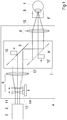
- the optical system shown in Fig.1 for an instrument for therapy of a human eye 1 represents the present state of prior art. It comprises a radiation source 2, which delivers a beam 3 of pulsed laser radiation in the femtosecond range, and a scanning device 4, with which the beam 3 is focussed onto selected positions within the region of the cornea. On the cornea there is a contact glass 5 that has a concave contact surface and suppresses movements of the eye 1 during treatment.
- the radiation source 2 is designed, e.g., to deliver laser radiation in the wavelength range around 1040 nm with a pulse width in the region of about 200 fs.
- the scanning device 4 has, in the direction of the beam 3 originating from the radiation source 2, an optical assembly 6, behind which in the beam direction, there follows a deflecting device 7. According to given control signals, the deflecting device 7 deflects the beam 3 exiting the optical assembly 6 in a lateral direction, i.e. in X- and Y-direction across the Z-direction of the incident beam 3. In the beam path, the deflecting device 7 is followed by an objective 8, which focuses the beam 3 into the region of the cornea.
- the deflecting device 7 is provided with two deflecting mirrors 9 and 9', which can be tilted about axes not shown in Fig.1 .
- the mirrors 9 and 9' are aligned in parallel, but actually the tilting axes are orthogonal to one another and to the optical axis of the optical assembly 6, so that tilting the first mirror 9 will deflect the beam 3 in Y-direction, and tilting the second mirror 9' will deflect it in X-direction orthogonal to it.
- the mirrors 9 and 9' are driven by actuators 10 and 10', respectively, which are connected with a control device via signal paths (marked by arrows). According to the desired focus position in lateral direction, the control device delivers control signals to the actuators 10 and 10', which thereupon cause the mirrors 9 and 9' to tilt.
- the optical assembly 6 is provided with a lens 11 of negative refractive power that can be moved relative to the deflecting device 7, and a collecting lens 12.
- the lens 11 is connected with a straight-line guideway 13 along which it can be shifted with a variable optically effective distance from the deflecting device 7.
- the shifting of the lens 11 can be actuated, e.g., by a linear drive motor 14, which is also connected to the control device that is not shown. Depending on the desired focus position in Z-direction, the control device generates control signals that go to the linear drive motor 14.
- the optical assembly 6 acts as an expander, which expands the diameter of the beam 3. If, then, a parallel beam 3 having a diameter d1 enters the optical assembly 6, the parallel beam 3 exiting the optical assembly 6 will have a diameter d2>d1.
- the objective 8 is shows as a fixed lens 15; it focuses the beam 3 exiting the optical assembly 6 onto a position in the region of the cornea, this position being determined by means of the lens 11 and the deflecting device 7.
- the position of the focus F in the depth of the region of the cornea is determined by the shifting of the lens 11 along its optical axis.
- the lateral position of the focus F is determined by the deflecting device 7.
- the problem is solved by the invention in such a way that the objective 8 itself is shiftable along the optical axis or that an objective 8 is provided that consists of several lens groups, with at least one of these lens groups being shiftable along the optical axis.
- the shifting of the objective 8 or of the lens group of the objective 8 is relative to the eye and relative to the other assemblies of the system, in such a way that this change of distance causes a shift of the focus position from the region of the cornea to the region of the crystalline lens, and vice versa.
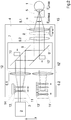
- Fig.2 illustrates the operating principle of the optical system according to the invention.
- the objective 8 consists of two lens groups 8.1 and 8.2, which, for the sake of clarity, are represented symbolically as single lenses.
- the lens group 8.2 is arranged in a fixed position in the beam path, whereas the lens group 8.1 can be shifted in the direction of the optical axis and, for this purpose, is coupled with a straight-line guideway, which in turn is connected with, e.g., a linear drive motor 15, which initiates the shifting movement and is therefore triggered by a control device (not shown).
- the distance by which the lens group 8.1 is shifted, while basically depending on the control signal, is favourably defined by two limit positions, of which a first limit position is marked in Fig.2 by the lens group 8.1 drawn in solid lines and the second limit position by the same lens group drawn in broken lines.
- the fixed shifting distance defined by the limit positions corresponds to the shifting of the focus position from the region of the cornea to the region of the crystalline lens and vice versa, by which it is made fundamentally possible that the laser therapy thus equipped can be used for treatments of both the cornea and the crystalline lens.
- the crystalline lens As explained before, extends in axial direction over a substantially greater region than the cornea, different focus variation ranges ⁇ z are required for the two configurations, and measures must be taken to ensure that, despite the shifting of the focus from the region of the cornea to the region of the crystalline lens and the different focus variation ranges ⁇ z required for the two configurations, aberrations are as small as possible and the numerical aperture is a great as possible for the given wavelength of the therapeutic radiation.
- this problem is solved by making separate optical assemblies 6.1, 6.2 available as expanders for each configuration and by exchanging these assemblies in the beam path for each other, preferably automatically with the shifting of the focus position from the region of the cornea to the region of the crystalline lens and vice versa.
- the lens group 8.1 is in its first limit position and if at the same time - as shown in Fig.2 - the optical assembly 6.1 is in the beam path between the radiation source 2 and the deflecting device 7, the focus position can be changed - by means of the lens 11 in within a focus variation range ⁇ z1 in Z-direction and by means of the deflecting device 7 in X- and Y-direction - in such a way that all desired targets within the region of the cornea can be reached with the desired optical precision.
- this also applies to the second limit position of the lens group 8.1.
- the optical assembly 6.2 is positioned in the beam path between radiation source 2 and deflecting device 7 in place of the optical assembly 6.1, and thus, it is possible to reach all desired targets within the region of the crystalline lens, and this with the desired optical precision as well.
- the shifting of the lens 11' in Z-direction now causes the shifting of the focus position within a focus variation range ⁇ z2, which corresponds to the extension of the region of the crystalline lens in the direction of the Z coordinate.
- the lateral variation of the focus position in X- and Y-direction within this region is accomplished by means of the deflecting device 7.
- the position/limit position of the lens group 8.1 for treating the crystalline lens is set as a function of the individual length of the eye, especially of the depth of the anterior chamber.
- Both optical assemblies 6.1, 6.2 are so designed that the axially shiftable lenses or lens groups 11 or 11', respectively, in spite of the optical starting parameters brought about by the shifting have one and the same shifting distance, so that one and the same linear drive motor 14 with a specified, fixed shifting distance can be used for both configurations.
- the optical gear ratios of the two assemblies 6.1, 6.2 differ, so that, if the two assemblies 6.1, 6.2 are interchanged, the diameter of the therapeutic laser beam and, consequently, the numerical aperture and/or the eye-side aperture angle of the therapeutic laser radiation will change.
- the optical assemblies 6.1, 6.2 consist of several lenses 11, 11', 12, 12' the axial distances between which can be varied. Due to the change of the axial distances, there will be a change of the refractive power situation within the optical assembly concerned, and thus a change of the axial focus position within the focus variation range ⁇ z1 or ⁇ z2, respectively.
- the interchange of the optical assemblies 6.1, 6.2 causes a change of the diameter of the therapeutic laser beam and consequently, a change in the numerical aperture regarding the optical system behind the optical assemblies 6.1, 6.2 in the therapeutic laser beam path, and/or a change in the eye-side aperture angle of the therapeutic laser radiation.
- Both optical assemblies 6.1, 6.2 have input and output interfaces in common with the other components of the optical system.
- the optical parameters at the input interface are always constant, whereas the output parameters vary depending on the optical assembly currently in the beam path and, thus, on the focus position to be set, and are characterized by different divergences and/or beam diameters.
- the changing device can be designed like a magazine, so that each of the two optical assemblies 6.1, 6.2 or also of further optical assemblies is assigned a mounting fixture, with which they, when required, are swivelled into the beam path about an axis of rotation or inserted by means of a straight-line guideway.
- the basic design of such magazines is known in prior art and needs no detailed description here.
Landscapes
- Health & Medical Sciences (AREA)
- Ophthalmology & Optometry (AREA)
- Heart & Thoracic Surgery (AREA)
- Vascular Medicine (AREA)
- Optics & Photonics (AREA)
- Surgery (AREA)
- Engineering & Computer Science (AREA)
- Biomedical Technology (AREA)
- Physics & Mathematics (AREA)
- Nuclear Medicine, Radiotherapy & Molecular Imaging (AREA)
- Life Sciences & Earth Sciences (AREA)
- Animal Behavior & Ethology (AREA)
- General Health & Medical Sciences (AREA)
- Public Health (AREA)
- Veterinary Medicine (AREA)
- Laser Surgery Devices (AREA)
Abstract
Description
- The present invention relates to an optical system for a laser therapy instrument for the application of laser radiation on and in the eye, suited particularly for laser surgery of the cornea and/or of the crystalline lens.
- Laser therapy instruments are used, e.g., for correcting an ametropia of the human eye by a laser-surgical operation of the cornea. For this purpose, a lid is formed on the outer surface of the cornea, which lid is attached along one edge and is therefore known as a flap, and the thickness of which is substantially smaller then the thickness of the cornea. For correction, this flap is folded back, and from the surface of the region of the cornea that is now exposed, tissue is removed thereupon by means of a laser beam pulsed in the femtosecond range, in order to change the curvature of the cornea. Such an instrument is described in
DE 10 2005 013 949 A1 - By contrast, a laser system described in
DE 10 2008 027 358 A1 - Typically, in either case the interaction between the ultrashort laser pulses and the tissue takes place in a small volume, hereafter referred to as focus volume. Situated within the focus volume is the interaction zone, in which the structural change, section or removal of the tissue takes place. The laser focus must be precisely positioned at the locus of the desired interaction. This is done with an optical focusing system, which projects the parallel laser beam from infinity at the object side into the treatment plane on the image side.
- This means that the precision achievable in the therapy is determined by the precision accuracy on the one hand, but also by the size of the interaction zone on the other. The size of the interaction zone, in turn, with a given laser pulse width, is essentially defined by the size of the focus volume. The smaller the focus volume, the smaller is the interaction zone, and the lesser is the risk of damage to the surrounding tissue, because with a small focus volume, the photon density needed for the treatment effect is achieved already with a very low laser pulse energy, such as about 10 nJ to 200 nJ; as a result, the energy input to the in the vicinity of the interaction zone is low.
- The size of the focus volume varies with the parameters of the optical system and with the wavelength of the therapeutic laser radiation. In other words: in connection with a given wavelength, the desired small size of the focus volume is made possible by small aberrations and a fairly high. With increasing numerical aperture, not only the lateral dimension of the focus shrinks, but also its axial dimension. From the viewpoint of application, the numerical aperture should preferably be as high as possible.
- The possibilities known in prior art of medical treatment of the cornea lying at the periphery of the eye on the one hand, and of the crystalline lens lying within the eye on the other, have the disadvantage that the instruments available satisfy the requirements of their respective special purpose only, which means that they differ, especially with regard to the focus position in the eye, the aperture and the size of the focus volume, to such an extent that they are designed and suitably either for therapy of the cornea alone or for therapy of the crystalline lens alone.
- This requires extensive instrumentation that is ineffective both with regard to purchase costs and because several separate instruments are used below their capacity most of the time. In addition, setting up the several instruments separately for examining and treating the same patient eye is time-consuming.
- While laser therapy instruments that can treat both the crystalline lens and the cornea are known, but they are originally optimized only for the treatment of the crystalline lens. They can be used, e.g., to make access cuts for cataract operations, but the precision achievable with them is insufficient for creating a flap. This is because axial focus movements by several millimetres are required if the laser focus is to reach the entire anterior segment of the eye including the crystalline lens.
- An essential problem to be solved in that respect is the fact that all object-side movements serving to vary the focus position (varying the parameters of the therapeutic laser beam before it enters the optical focussing system, e.g., by the shifting of lenses within the optical systems arranged further up the beam or by the movement of scanning mirrors) will inevitably result in a change von beam paths within the optical focussing system. The term "optical focussing system", in this context, stands for the objective from which the therapeutic laser radiation exits and is focussed on and directed at the eye. If, e.g., the axial position of the laser focus is shifted in this way, the aberrations occurring as a function of this variation will have a disadvantageous effect on the focus volume.
- An optical focussing system or an objective that is optimized only for a particular focus position in axial direction always is a compromise between the spatial region accessible by the focus position and the size of the aberrations occurring within this region. As the same is true also for the lateral extension of the spatial region accessible by the laser focus, there is always a restriction of the entire spatial region in which the necessary focus quality is to be achieved.
- Departing from this, the invention is based on the problem of creating an optical system for a laser therapy instrument which can be used alternately for laser surgery of the cornea and of the crystalline lens with high precision in both uses.
- According to the invention, this problem is solved by an optical system having the features specified in
Claim 1. Technical features of further developments of the invention are given inClaims 2 to 12. - Note on the definition of terms: In the sense of the invention, the term "axial" defines the direction of the Z coordinate, and the term "lateral" defines the X and Y coordinate directions.
- The inventive idea is based on the fact that the anterior segment of the eye consists essentially of two tissue regions that are of interest to laser surgery, i.e. the region of the cornea with a thickness of approximately 0.5 to 2 mm measured in the direction of radiation on the one hand, and the region of the crystalline lens with a substantially greater thickness of about 2 mm to 6 mm on the other hand. In between there is the anterior chamber filled with aqueous humour.
- Consequently, for the most frequent therapies of the eye it is not necessary to design the optical system in such a way that the entire anterior segment of the eye can be accessed by the focus with an object-side axial scanning movement. It is sufficient to direct the focus separately to the region of the crystalline lens and the region of the cornea. Because of that, the actually very large object-side Z scanning range is limited to two separate tissue regions lying between the front surface of the cornea and the rear surface of the lens. While these tissue regions are spaced at a considerable distance from each other, one of them covers only slightly more than the cornea thickness and the other only slightly more than the thickness of the crystalline lens. This makes it possible to induce fewer aberrations.
- According to the invention, a configurable objective is used; in a first configuration, the focus position lies in a region comprising the cornea, and in a second configuration, the focus position lies in a region comprising the crystalline lens and the lens capsule. Both configurations can be achieved by at least one of the following measures:
- Changes of air gaps between single or several lenses,
- Changes of lens radii of one or several lenses,
- Changes of refractive index of one or several lenses,
- Insertion or exchange of single lenses or lens groups.
- In that way, at least the two states are achieved that are optimally adapted to the respective focus position and thus have the least aberrations in these two configurations. This makes it possible to precisely vary the focus axially by object-side divergence variation in the region of the cornea or of the crystalline lens, respectively.
- The optical assemblies arranged before the focussing objective in the direction of radiation for the purpose of divergence variation are so designed optically that the focus variation ranges Δz for the cornea and also for the crystalline lens including the lens capsule are covered completely. According to the invention this is accomplished with certain "optical gear" ratios of the moved lenses or lens groups in these assemblies, in the context of the invention also called expanders. The gear ratio is designed to be a large as possible in order to achieve a very high accuracy of the Z position of the focus. According to the invention, the optical gear ratios between lens or lens group movements and focus position changes are computed or measured, saved as system parameters and taken into account by way of correction when the focus position is varied.
- Axial resolution losses occurring upon switching between the two configurations are avoided in that the optical design of the expanders is coupled to the configuration change, preferably in that two expanders in the therapeutic laser beam path are exchanged against one another. Both expanders have beam path lengths which are independent of one another and are inserted into the beam path alternatingly depending on the configuration selected by the user.
- Because of the varied depths of the focus positions in the anterior segment of the eye, there is, for each focus position, a maximum useful aperture, which is limited because of the free optical diameter of the optical focussing system and because of the anatomy of the eye, especially due to the shadowing of the iris in treatments of the crystalline lens. In case of smaller axial focus positions, such as occurring in treatments of the cornea, larger apertures can be used to advantage, with the associated advantages of the more compact focus volume, whereas in case of greater axial focus positions, i.e. in the region of the crystalline lens, it is of advantage not to fully utilize the technically available aperture of the optical focussing system but rather to use only the aperture that can effectively be utilized depending on the application. According to the invention, this is done by means of a reduced beam diameter at the entrance pupil of the optical focussing system.
- The adaptation of the beam diameter to the configuration selected is accomplished by changing the expanders. In this way, a combined optical system results, which is adapted optimally to treatment of the cornea on the one hand, and, likewise optimally, to treatment of the crystalline lens on the other; this means that in either case the axial resolution is as high, and the numerical aperture as large, as possible technically and with regard to the application, while the aberrations of the system are, in either case, as small as possible.
- It is also within the scope of the inventive idea to introduce a third axial focus variation range Δz into optical system, e.g., for the purpose of manipulations in the anterior chamber of the eye, for vitreous body surgery or for therapies in the region of the retina.
- The configuration change will also cause a change of field curvature depending on the real focus position. It is within the scope of the invention to compute or measure the field curvature, to save it as a system parameter as well and to take it into account in focussing by way of correction.
- Below, the invention will be explained in greater detail with reference to exemplary embodiments. In the accompanying drawings,
- Fig.1
- is a schematic illustration of the optical system for a laser therapy instrument for the application of laser radiation as known in prior art, and
- Fig.2
- is a schematic illustration of the invented optical system for a laser therapy instrument in a preferred embodiment.
- The optical system shown in
Fig.1 , for an instrument for therapy of ahuman eye 1 represents the present state of prior art. It comprises aradiation source 2, which delivers abeam 3 of pulsed laser radiation in the femtosecond range, and a scanning device 4, with which thebeam 3 is focussed onto selected positions within the region of the cornea. On the cornea there is acontact glass 5 that has a concave contact surface and suppresses movements of theeye 1 during treatment. - The
radiation source 2 is designed, e.g., to deliver laser radiation in the wavelength range around 1040 nm with a pulse width in the region of about 200 fs. - The scanning device 4 has, in the direction of the
beam 3 originating from theradiation source 2, anoptical assembly 6, behind which in the beam direction, there follows adeflecting device 7. According to given control signals, the deflectingdevice 7 deflects thebeam 3 exiting theoptical assembly 6 in a lateral direction, i.e. in X- and Y-direction across the Z-direction of theincident beam 3. In the beam path, the deflectingdevice 7 is followed by anobjective 8, which focuses thebeam 3 into the region of the cornea. - The deflecting
device 7 is provided with two deflectingmirrors 9 and 9', which can be tilted about axes not shown inFig.1 . In the simplified representation according toFig.1 , themirrors 9 and 9' are aligned in parallel, but actually the tilting axes are orthogonal to one another and to the optical axis of theoptical assembly 6, so that tilting thefirst mirror 9 will deflect thebeam 3 in Y-direction, and tilting the second mirror 9' will deflect it in X-direction orthogonal to it. Themirrors 9 and 9' are driven byactuators 10 and 10', respectively, which are connected with a control device via signal paths (marked by arrows). According to the desired focus position in lateral direction, the control device delivers control signals to theactuators 10 and 10', which thereupon cause themirrors 9 and 9' to tilt. - The
optical assembly 6 is provided with alens 11 of negative refractive power that can be moved relative to thedeflecting device 7, and a collectinglens 12. Thelens 11 is connected with a straight-line guideway 13 along which it can be shifted with a variable optically effective distance from the deflectingdevice 7. The shifting of thelens 11 can be actuated, e.g., by alinear drive motor 14, which is also connected to the control device that is not shown. Depending on the desired focus position in Z-direction, the control device generates control signals that go to thelinear drive motor 14. - Due to the design of the
lens 11 and the collectinglens 12, theoptical assembly 6 acts as an expander, which expands the diameter of thebeam 3. If, then, aparallel beam 3 having a diameter d1 enters theoptical assembly 6, theparallel beam 3 exiting theoptical assembly 6 will have a diameter d2>d1. - The
objective 8 is shows as a fixedlens 15; it focuses thebeam 3 exiting theoptical assembly 6 onto a position in the region of the cornea, this position being determined by means of thelens 11 and thedeflecting device 7. The position of the focus F in the depth of the region of the cornea is determined by the shifting of thelens 11 along its optical axis. The lateral position of the focus F is determined by the deflectingdevice 7. - For further details of this, see
publication DE 10 2005 013 949 A1 . - Departing from the prior art as described above, the problem is solved by the invention in such a way that the
objective 8 itself is shiftable along the optical axis or that anobjective 8 is provided that consists of several lens groups, with at least one of these lens groups being shiftable along the optical axis. The shifting of theobjective 8 or of the lens group of theobjective 8 is relative to the eye and relative to the other assemblies of the system, in such a way that this change of distance causes a shift of the focus position from the region of the cornea to the region of the crystalline lens, and vice versa. -
Fig.2 illustrates the operating principle of the optical system according to the invention. In this preferred embodiment, theobjective 8 consists of two lens groups 8.1 and 8.2, which, for the sake of clarity, are represented symbolically as single lenses. The lens group 8.2 is arranged in a fixed position in the beam path, whereas the lens group 8.1 can be shifted in the direction of the optical axis and, for this purpose, is coupled with a straight-line guideway, which in turn is connected with, e.g., alinear drive motor 15, which initiates the shifting movement and is therefore triggered by a control device (not shown). - The distance by which the lens group 8.1 is shifted, while basically depending on the control signal, is favourably defined by two limit positions, of which a first limit position is marked in
Fig.2 by the lens group 8.1 drawn in solid lines and the second limit position by the same lens group drawn in broken lines. - The fixed shifting distance defined by the limit positions corresponds to the shifting of the focus position from the region of the cornea to the region of the crystalline lens and vice versa, by which it is made fundamentally possible that the laser therapy thus equipped can be used for treatments of both the cornea and the crystalline lens.
- As the crystalline lens, as explained before, extends in axial direction over a substantially greater region than the cornea, different focus variation ranges Δz are required for the two configurations, and measures must be taken to ensure that, despite the shifting of the focus from the region of the cornea to the region of the crystalline lens and the different focus variation ranges Δz required for the two configurations, aberrations are as small as possible and the numerical aperture is a great as possible for the given wavelength of the therapeutic radiation.
- According to the invention, this problem is solved by making separate optical assemblies 6.1, 6.2 available as expanders for each configuration and by exchanging these assemblies in the beam path for each other, preferably automatically with the shifting of the focus position from the region of the cornea to the region of the crystalline lens and vice versa.
- If, for example, the lens group 8.1 is in its first limit position and if at the same time - as shown in
Fig.2 - the optical assembly 6.1 is in the beam path between theradiation source 2 and thedeflecting device 7, the focus position can be changed - by means of thelens 11 in within a focus variation range Δz1 in Z-direction and by means of thedeflecting device 7 in X- and Y-direction - in such a way that all desired targets within the region of the cornea can be reached with the desired optical precision. - Analogously, this also applies to the second limit position of the lens group 8.1. Simultaneously with the shifting of the lens group 8.1 its second limit position and, thus, the change of system configuration, the optical assembly 6.2 is positioned in the beam path between
radiation source 2 and deflectingdevice 7 in place of the optical assembly 6.1, and thus, it is possible to reach all desired targets within the region of the crystalline lens, and this with the desired optical precision as well. The shifting of the lens 11' in Z-direction now causes the shifting of the focus position within a focus variation range Δz2, which corresponds to the extension of the region of the crystalline lens in the direction of the Z coordinate. The lateral variation of the focus position in X- and Y-direction within this region is accomplished by means of thedeflecting device 7. - Since patient naturally differ in size and particularly in length, in a special embodiment of the invention the position/limit position of the lens group 8.1 for treating the crystalline lens is set as a function of the individual length of the eye, especially of the depth of the anterior chamber.
- Both optical assemblies 6.1, 6.2 are so designed that the axially shiftable lenses or
lens groups 11 or 11', respectively, in spite of the optical starting parameters brought about by the shifting have one and the same shifting distance, so that one and the samelinear drive motor 14 with a specified, fixed shifting distance can be used for both configurations. However, the optical gear ratios of the two assemblies 6.1, 6.2 differ, so that, if the two assemblies 6.1, 6.2 are interchanged, the diameter of the therapeutic laser beam and, consequently, the numerical aperture and/or the eye-side aperture angle of the therapeutic laser radiation will change. - It is essential for the inventive idea that the optical assemblies 6.1, 6.2 consist of
several lenses - Both optical assemblies 6.1, 6.2 have input and output interfaces in common with the other components of the optical system. The optical parameters at the input interface are always constant, whereas the output parameters vary depending on the optical assembly currently in the beam path and, thus, on the focus position to be set, and are characterized by different divergences and/or beam diameters.
- In all embodiment versions of the invention, the changing device can be designed like a magazine, so that each of the two optical assemblies 6.1, 6.2 or also of further optical assemblies is assigned a mounting fixture, with which they, when required, are swivelled into the beam path about an axis of rotation or inserted by means of a straight-line guideway. The basic design of such magazines is known in prior art and needs no detailed description here.
-
- 1
- eye
- 2
- radiation source
- 3
- radiation beam
- 4
- scanning device
- 5
- contact glass
- 6
- optical assembly
- 7
- deflecting device
- 8
- objective
- 8.1, 8.2
- lens groups
- 9,9'
- mirrors
- 10, 10'
- actuators
- 11, 11'
- lenses
- 12, 12'
- collective lenses
- 13, 13'
- straight-line guideway
- 14
- linear drive motor
- 15
- linear drive motor
Claims (6)
- An optical system for a laser therapy instrument, suitable for laser surgery of the cornea and the crystalline lens of a human patient's eye, comprising:- a femtosecond laser as a radiation source (2) for the therapeutic laser radiation,- an objective (8) from which the therapeutic laser radiation exits and is directed and focussed on to or into the eye,- the objective (8) being configurable to direct the focus separately to a region comprising the cornea in a first configuration, and to a region comprising the crystalline lens and the lens capsule in a second configuration, thereby limiting an object-side Z scanning range to two separate regions lying between the front surface of the cornea and the rear surface of the lens.
- The optical system as claimed in Claim 1, in which for switching between the first and second configuration of the objective (8)- (i) air gaps between single lenses or several lenses of the objective (8) are changeable, and/or- (ii) lens radii of one or several lenses of the objective (8) are changeable, and/or- (iii) refractive indices of one or several lenses of the objective (8) are changeable, and/or- (iv) single lenses or lens groups of the objective (8) are exchangeable with other single lenses or lens groups, and/or- (v) further lenses or lens groups are insertable into the objective (8).
- The optical system as claimed in claim 1 or 2, in which the objective (8) itself or at least one lens or lens group (8.1, 8.2) of the objective (8) is shiftable in the direction of the optical axis relative to the other lenses or lens groups of the system, and this shifting is intended for a shifting of the focus position from the region of the cornea to the region of the crystalline lens and vice versa.
- The optical system as claimed in Claim 3, in which the shifting of the objective (8) itself or at least of one lens or lens group (8.1, 8.2) of the objective (8) in the direction of the optical axis relative to the other lenses or lens groups of the system depends on the individual eye length, especially on the depth of the anterior chamber.
- The optical system as claimed in any of Claims 1 to 4, further comprising two optical assemblies (6,1, 6.2) which are designed for varying the focus of the therapeutic laser radiation, with different focus variation ranges Δz of the individual assemblies (6.1, 6.2), and which are insertable into the beam path alternatingly depending on the first or second configuration of the objective (8).
- The optical system as claimed in Claim 5, further comprising means for automatically exchanging the two optical assemblies (6.1, 6.2) in the beam path for each other with the shifting of the focus position from the region of the cornea to the region of the crystalline lens and vice versa.
Applications Claiming Priority (4)
| Application Number | Priority Date | Filing Date | Title |
|---|---|---|---|
| US201161485995P | 2011-05-13 | 2011-05-13 | |
| DE102011075799A DE102011075799A1 (en) | 2011-05-13 | 2011-05-13 | Optical system for a laser therapy device |
| EP12713631.5A EP2706969B1 (en) | 2011-05-13 | 2012-03-19 | Optical system for a laser therapy instrument |
| PCT/EP2012/054743 WO2012156122A1 (en) | 2011-05-13 | 2012-03-19 | Optical system for a laser therapy instrument |
Related Parent Applications (2)
| Application Number | Title | Priority Date | Filing Date |
|---|---|---|---|
| PCT/EP2012/054743 Previously-Filed-Application WO2012156122A1 (en) | 2011-05-13 | 2012-03-19 | Optical system for a laser therapy instrument |
| EP12713631.5A Division EP2706969B1 (en) | 2011-05-13 | 2012-03-19 | Optical system for a laser therapy instrument |
Publications (2)
| Publication Number | Publication Date |
|---|---|
| EP3275411A1 true EP3275411A1 (en) | 2018-01-31 |
| EP3275411B1 EP3275411B1 (en) | 2020-11-11 |
Family
ID=47070380
Family Applications (2)
| Application Number | Title | Priority Date | Filing Date |
|---|---|---|---|
| EP17167182.9A Active EP3275411B1 (en) | 2011-05-13 | 2012-03-19 | Optical system for a laser therapy instrument |
| EP12713631.5A Active EP2706969B1 (en) | 2011-05-13 | 2012-03-19 | Optical system for a laser therapy instrument |
Family Applications After (1)
| Application Number | Title | Priority Date | Filing Date |
|---|---|---|---|
| EP12713631.5A Active EP2706969B1 (en) | 2011-05-13 | 2012-03-19 | Optical system for a laser therapy instrument |
Country Status (4)
| Country | Link |
|---|---|
| US (3) | US10478340B2 (en) |
| EP (2) | EP3275411B1 (en) |
| DE (1) | DE102011075799A1 (en) |
| WO (1) | WO2012156122A1 (en) |
Families Citing this family (4)
| Publication number | Priority date | Publication date | Assignee | Title |
|---|---|---|---|---|
| DE102011075799A1 (en) * | 2011-05-13 | 2012-11-15 | Carl Zeiss Meditec Ag | Optical system for a laser therapy device |
| CN104720972B (en) * | 2015-03-17 | 2016-11-30 | 温州医科大学 | A kind of intelligent storage for laser therapeutic apparatus and real-time monitoring and display system |
| DE102017126291A1 (en) * | 2017-11-09 | 2019-05-09 | Compact Laser Solutions Gmbh | Device for generating a laser radiation |
| DE102020113693B4 (en) * | 2020-05-20 | 2023-02-23 | Schwind Eye-Tech-Solutions Gmbh | Beam deflection device for a laser device, laser device, method for generating a laser pattern and computer program and computer-readable medium |
Citations (4)
| Publication number | Priority date | Publication date | Assignee | Title |
|---|---|---|---|---|
| GB2359375A (en) * | 2000-02-15 | 2001-08-22 | Ian Marshall | Ophthalmoscope optical system |
| US20090299347A1 (en) * | 2008-04-22 | 2009-12-03 | Wavelight Ag | Device for Laser-Optical Eye Surgery |
| US20110028953A1 (en) * | 2009-07-29 | 2011-02-03 | Lensx Lasers, Inc. | Optical System for Ophthalmic Surgical Laser |
| WO2012130480A1 (en) * | 2011-03-25 | 2012-10-04 | Carl Zeiss Meditec Ag | Ophthalmological device |
Family Cites Families (16)
| Publication number | Priority date | Publication date | Assignee | Title |
|---|---|---|---|---|
| US3720213A (en) * | 1971-02-05 | 1973-03-13 | Coherent Radiation | Laser photocoagulator |
| US5837962A (en) * | 1996-07-15 | 1998-11-17 | Overbeck; James W. | Faster laser marker employing acousto-optic deflection |
| US6637882B1 (en) * | 1998-11-24 | 2003-10-28 | Welch Allyn, Inc. | Eye viewing device for retinal viewing through undilated pupil |
| US6685317B2 (en) * | 2000-06-13 | 2004-02-03 | Massie Research Laboratories, Inc. | Digital eye camera |
| AUPS158302A0 (en) * | 2002-04-09 | 2002-05-16 | Scan Optics Pty Ltd | Improved fundus camera |
| US6741359B2 (en) * | 2002-05-22 | 2004-05-25 | Carl Zeiss Meditec, Inc. | Optical coherence tomography optical scanner |
| WO2006078802A1 (en) * | 2005-01-21 | 2006-07-27 | Massachusetts Institute Of Technology | Methods and apparatus for optical coherence tomography scanning |
| DE102005013949A1 (en) | 2005-03-26 | 2006-09-28 | Carl Zeiss Meditec Ag | scanning device |
| KR20080078417A (en) * | 2007-02-23 | 2008-08-27 | 삼성전자주식회사 | Compatible optical pickup and optical information storage media system using the same |
| US8617147B2 (en) * | 2007-06-26 | 2013-12-31 | University Of Rochester | Method for modifying the refractive index of ocular tissues |
| EP2826436B1 (en) | 2007-09-06 | 2018-03-28 | Alcon LenSx, Inc. | Precise targeting of surgical photodisruption |
| US20090149841A1 (en) * | 2007-09-10 | 2009-06-11 | Kurtz Ronald M | Effective Laser Photodisruptive Surgery in a Gravity Field |
| EP2200549A4 (en) * | 2007-09-18 | 2013-01-23 | Alcon Lensx Inc | Methods and apparatus for integrated cataract surgery |
| DE102008027358A1 (en) | 2008-06-05 | 2009-12-10 | Carl Zeiss Meditec Ag | Ophthalmic laser system and operating procedures |
| DE102009005482A1 (en) * | 2009-01-21 | 2010-07-22 | Carl Zeiss Meditec Ag | Device and method for generating control data for the surgical ametropia correction of an eye |
| DE102011075799A1 (en) | 2011-05-13 | 2012-11-15 | Carl Zeiss Meditec Ag | Optical system for a laser therapy device |
-
2011
- 2011-05-13 DE DE102011075799A patent/DE102011075799A1/en active Pending
-
2012
- 2012-03-19 WO PCT/EP2012/054743 patent/WO2012156122A1/en not_active Ceased
- 2012-03-19 EP EP17167182.9A patent/EP3275411B1/en active Active
- 2012-03-19 EP EP12713631.5A patent/EP2706969B1/en active Active
- 2012-03-19 US US14/116,471 patent/US10478340B2/en active Active
-
2019
- 2019-11-14 US US16/684,048 patent/US11351061B2/en active Active
-
2022
- 2022-06-03 US US17/805,273 patent/US11865043B2/en active Active
Patent Citations (4)
| Publication number | Priority date | Publication date | Assignee | Title |
|---|---|---|---|---|
| GB2359375A (en) * | 2000-02-15 | 2001-08-22 | Ian Marshall | Ophthalmoscope optical system |
| US20090299347A1 (en) * | 2008-04-22 | 2009-12-03 | Wavelight Ag | Device for Laser-Optical Eye Surgery |
| US20110028953A1 (en) * | 2009-07-29 | 2011-02-03 | Lensx Lasers, Inc. | Optical System for Ophthalmic Surgical Laser |
| WO2012130480A1 (en) * | 2011-03-25 | 2012-10-04 | Carl Zeiss Meditec Ag | Ophthalmological device |
Also Published As
| Publication number | Publication date |
|---|---|
| EP2706969A1 (en) | 2014-03-19 |
| US20220370241A1 (en) | 2022-11-24 |
| US11351061B2 (en) | 2022-06-07 |
| WO2012156122A1 (en) | 2012-11-22 |
| EP3275411B1 (en) | 2020-11-11 |
| US11865043B2 (en) | 2024-01-09 |
| EP2706969B1 (en) | 2017-05-03 |
| US10478340B2 (en) | 2019-11-19 |
| US20200237554A1 (en) | 2020-07-30 |
| DE102011075799A1 (en) | 2012-11-15 |
| US20140114295A1 (en) | 2014-04-24 |
Similar Documents
| Publication | Publication Date | Title |
|---|---|---|
| US11865043B2 (en) | Optical system for a laser therapy instrument | |
| EP3829503B1 (en) | Full depth laser ophthalmic surgical system | |
| EP3003123B1 (en) | Optical coherence tomography imaging system and optical laser scanning system comprising a beam shaping optical system with a +-+ lens triplet, where second and third lens are movable, and method | |
| US10322031B2 (en) | Ophthalmological device | |
| JP6306796B2 (en) | Mobile wide-angle ophthalmic surgery system | |
| US8506559B2 (en) | Variable stage optical system for ophthalmic surgical laser | |
| US11872161B2 (en) | Ophthalmic surgery laser system and method for utilizing same for ophthalmic surgery | |
| US20180214306A1 (en) | Ophthalmic surgical apparatus | |
| EP2837368A2 (en) | Ophthalmic laser surgical apparatus | |
| US20240058169A1 (en) | System and method for accessing different tissue targets of the eye | |
| RU2563448C1 (en) | Ophthalmosurgical laser system | |
| US20260069458A1 (en) | Laser beam aperture control techniques for ophthalmic surgical equipment |
Legal Events
| Date | Code | Title | Description |
|---|---|---|---|
| PUAI | Public reference made under article 153(3) epc to a published international application that has entered the european phase |
Free format text: ORIGINAL CODE: 0009012 |
|
| STAA | Information on the status of an ep patent application or granted ep patent |
Free format text: STATUS: THE APPLICATION HAS BEEN PUBLISHED |
|
| AC | Divisional application: reference to earlier application |
Ref document number: 2706969 Country of ref document: EP Kind code of ref document: P |
|
| AK | Designated contracting states |
Kind code of ref document: A1 Designated state(s): AL AT BE BG CH CY CZ DE DK EE ES FI FR GB GR HR HU IE IS IT LI LT LU LV MC MK MT NL NO PL PT RO RS SE SI SK SM TR |
|
| STAA | Information on the status of an ep patent application or granted ep patent |
Free format text: STATUS: REQUEST FOR EXAMINATION WAS MADE |
|
| 17P | Request for examination filed |
Effective date: 20180705 |
|
| RBV | Designated contracting states (corrected) |
Designated state(s): AL AT BE BG CH CY CZ DE DK EE ES FI FR GB GR HR HU IE IS IT LI LT LU LV MC MK MT NL NO PL PT RO RS SE SI SK SM TR |
|
| STAA | Information on the status of an ep patent application or granted ep patent |
Free format text: STATUS: EXAMINATION IS IN PROGRESS |
|
| 17Q | First examination report despatched |
Effective date: 20190201 |
|
| GRAP | Despatch of communication of intention to grant a patent |
Free format text: ORIGINAL CODE: EPIDOSNIGR1 |
|
| STAA | Information on the status of an ep patent application or granted ep patent |
Free format text: STATUS: GRANT OF PATENT IS INTENDED |
|
| INTG | Intention to grant announced |
Effective date: 20200110 |
|
| GRAJ | Information related to disapproval of communication of intention to grant by the applicant or resumption of examination proceedings by the epo deleted |
Free format text: ORIGINAL CODE: EPIDOSDIGR1 |
|
| STAA | Information on the status of an ep patent application or granted ep patent |
Free format text: STATUS: EXAMINATION IS IN PROGRESS |
|
| GRAP | Despatch of communication of intention to grant a patent |
Free format text: ORIGINAL CODE: EPIDOSNIGR1 |
|
| STAA | Information on the status of an ep patent application or granted ep patent |
Free format text: STATUS: GRANT OF PATENT IS INTENDED |
|
| INTC | Intention to grant announced (deleted) | ||
| INTG | Intention to grant announced |
Effective date: 20200605 |
|
| GRAS | Grant fee paid |
Free format text: ORIGINAL CODE: EPIDOSNIGR3 |
|
| GRAA | (expected) grant |
Free format text: ORIGINAL CODE: 0009210 |
|
| STAA | Information on the status of an ep patent application or granted ep patent |
Free format text: STATUS: THE PATENT HAS BEEN GRANTED |
|
| AC | Divisional application: reference to earlier application |
Ref document number: 2706969 Country of ref document: EP Kind code of ref document: P |
|
| AK | Designated contracting states |
Kind code of ref document: B1 Designated state(s): AL AT BE BG CH CY CZ DE DK EE ES FI FR GB GR HR HU IE IS IT LI LT LU LV MC MK MT NL NO PL PT RO RS SE SI SK SM TR |
|
| REG | Reference to a national code |
Ref country code: GB Ref legal event code: FG4D |
|
| REG | Reference to a national code |
Ref country code: CH Ref legal event code: EP |
|
| REG | Reference to a national code |
Ref country code: AT Ref legal event code: REF Ref document number: 1332754 Country of ref document: AT Kind code of ref document: T Effective date: 20201115 |
|
| REG | Reference to a national code |
Ref country code: DE Ref legal event code: R096 Ref document number: 602012073236 Country of ref document: DE |
|
| REG | Reference to a national code |
Ref country code: IE Ref legal event code: FG4D |
|
| REG | Reference to a national code |
Ref country code: NL Ref legal event code: MP Effective date: 20201111 |
|
| REG | Reference to a national code |
Ref country code: AT Ref legal event code: MK05 Ref document number: 1332754 Country of ref document: AT Kind code of ref document: T Effective date: 20201111 |
|
| PG25 | Lapsed in a contracting state [announced via postgrant information from national office to epo] |
Ref country code: NO Free format text: LAPSE BECAUSE OF FAILURE TO SUBMIT A TRANSLATION OF THE DESCRIPTION OR TO PAY THE FEE WITHIN THE PRESCRIBED TIME-LIMIT Effective date: 20210211 Ref country code: PT Free format text: LAPSE BECAUSE OF FAILURE TO SUBMIT A TRANSLATION OF THE DESCRIPTION OR TO PAY THE FEE WITHIN THE PRESCRIBED TIME-LIMIT Effective date: 20210311 Ref country code: RS Free format text: LAPSE BECAUSE OF FAILURE TO SUBMIT A TRANSLATION OF THE DESCRIPTION OR TO PAY THE FEE WITHIN THE PRESCRIBED TIME-LIMIT Effective date: 20201111 Ref country code: FI Free format text: LAPSE BECAUSE OF FAILURE TO SUBMIT A TRANSLATION OF THE DESCRIPTION OR TO PAY THE FEE WITHIN THE PRESCRIBED TIME-LIMIT Effective date: 20201111 Ref country code: GR Free format text: LAPSE BECAUSE OF FAILURE TO SUBMIT A TRANSLATION OF THE DESCRIPTION OR TO PAY THE FEE WITHIN THE PRESCRIBED TIME-LIMIT Effective date: 20210212 |
|
| PG25 | Lapsed in a contracting state [announced via postgrant information from national office to epo] |
Ref country code: AT Free format text: LAPSE BECAUSE OF FAILURE TO SUBMIT A TRANSLATION OF THE DESCRIPTION OR TO PAY THE FEE WITHIN THE PRESCRIBED TIME-LIMIT Effective date: 20201111 Ref country code: BG Free format text: LAPSE BECAUSE OF FAILURE TO SUBMIT A TRANSLATION OF THE DESCRIPTION OR TO PAY THE FEE WITHIN THE PRESCRIBED TIME-LIMIT Effective date: 20210211 Ref country code: PL Free format text: LAPSE BECAUSE OF FAILURE TO SUBMIT A TRANSLATION OF THE DESCRIPTION OR TO PAY THE FEE WITHIN THE PRESCRIBED TIME-LIMIT Effective date: 20201111 Ref country code: LV Free format text: LAPSE BECAUSE OF FAILURE TO SUBMIT A TRANSLATION OF THE DESCRIPTION OR TO PAY THE FEE WITHIN THE PRESCRIBED TIME-LIMIT Effective date: 20201111 Ref country code: IS Free format text: LAPSE BECAUSE OF FAILURE TO SUBMIT A TRANSLATION OF THE DESCRIPTION OR TO PAY THE FEE WITHIN THE PRESCRIBED TIME-LIMIT Effective date: 20210311 Ref country code: SE Free format text: LAPSE BECAUSE OF FAILURE TO SUBMIT A TRANSLATION OF THE DESCRIPTION OR TO PAY THE FEE WITHIN THE PRESCRIBED TIME-LIMIT Effective date: 20201111 |
|
| REG | Reference to a national code |
Ref country code: LT Ref legal event code: MG9D |
|
| PG25 | Lapsed in a contracting state [announced via postgrant information from national office to epo] |
Ref country code: HR Free format text: LAPSE BECAUSE OF FAILURE TO SUBMIT A TRANSLATION OF THE DESCRIPTION OR TO PAY THE FEE WITHIN THE PRESCRIBED TIME-LIMIT Effective date: 20201111 |
|
| PG25 | Lapsed in a contracting state [announced via postgrant information from national office to epo] |
Ref country code: SM Free format text: LAPSE BECAUSE OF FAILURE TO SUBMIT A TRANSLATION OF THE DESCRIPTION OR TO PAY THE FEE WITHIN THE PRESCRIBED TIME-LIMIT Effective date: 20201111 Ref country code: RO Free format text: LAPSE BECAUSE OF FAILURE TO SUBMIT A TRANSLATION OF THE DESCRIPTION OR TO PAY THE FEE WITHIN THE PRESCRIBED TIME-LIMIT Effective date: 20201111 Ref country code: SK Free format text: LAPSE BECAUSE OF FAILURE TO SUBMIT A TRANSLATION OF THE DESCRIPTION OR TO PAY THE FEE WITHIN THE PRESCRIBED TIME-LIMIT Effective date: 20201111 Ref country code: LT Free format text: LAPSE BECAUSE OF FAILURE TO SUBMIT A TRANSLATION OF THE DESCRIPTION OR TO PAY THE FEE WITHIN THE PRESCRIBED TIME-LIMIT Effective date: 20201111 Ref country code: EE Free format text: LAPSE BECAUSE OF FAILURE TO SUBMIT A TRANSLATION OF THE DESCRIPTION OR TO PAY THE FEE WITHIN THE PRESCRIBED TIME-LIMIT Effective date: 20201111 |
|
| REG | Reference to a national code |
Ref country code: DE Ref legal event code: R097 Ref document number: 602012073236 Country of ref document: DE |
|
| PG25 | Lapsed in a contracting state [announced via postgrant information from national office to epo] |
Ref country code: DK Free format text: LAPSE BECAUSE OF FAILURE TO SUBMIT A TRANSLATION OF THE DESCRIPTION OR TO PAY THE FEE WITHIN THE PRESCRIBED TIME-LIMIT Effective date: 20201111 |
|
| PLBE | No opposition filed within time limit |
Free format text: ORIGINAL CODE: 0009261 |
|
| STAA | Information on the status of an ep patent application or granted ep patent |
Free format text: STATUS: NO OPPOSITION FILED WITHIN TIME LIMIT |
|
| 26N | No opposition filed |
Effective date: 20210812 |
|
| PG25 | Lapsed in a contracting state [announced via postgrant information from national office to epo] |
Ref country code: IT Free format text: LAPSE BECAUSE OF FAILURE TO SUBMIT A TRANSLATION OF THE DESCRIPTION OR TO PAY THE FEE WITHIN THE PRESCRIBED TIME-LIMIT Effective date: 20201111 Ref country code: MC Free format text: LAPSE BECAUSE OF FAILURE TO SUBMIT A TRANSLATION OF THE DESCRIPTION OR TO PAY THE FEE WITHIN THE PRESCRIBED TIME-LIMIT Effective date: 20201111 Ref country code: NL Free format text: LAPSE BECAUSE OF FAILURE TO SUBMIT A TRANSLATION OF THE DESCRIPTION OR TO PAY THE FEE WITHIN THE PRESCRIBED TIME-LIMIT Effective date: 20201111 Ref country code: AL Free format text: LAPSE BECAUSE OF FAILURE TO SUBMIT A TRANSLATION OF THE DESCRIPTION OR TO PAY THE FEE WITHIN THE PRESCRIBED TIME-LIMIT Effective date: 20201111 |
|
| GBPC | Gb: european patent ceased through non-payment of renewal fee |
Effective date: 20210319 |
|
| PG25 | Lapsed in a contracting state [announced via postgrant information from national office to epo] |
Ref country code: SI Free format text: LAPSE BECAUSE OF FAILURE TO SUBMIT A TRANSLATION OF THE DESCRIPTION OR TO PAY THE FEE WITHIN THE PRESCRIBED TIME-LIMIT Effective date: 20201111 |
|
| REG | Reference to a national code |
Ref country code: BE Ref legal event code: MM Effective date: 20210331 |
|
| PG25 | Lapsed in a contracting state [announced via postgrant information from national office to epo] |
Ref country code: ES Free format text: LAPSE BECAUSE OF FAILURE TO SUBMIT A TRANSLATION OF THE DESCRIPTION OR TO PAY THE FEE WITHIN THE PRESCRIBED TIME-LIMIT Effective date: 20201111 Ref country code: GB Free format text: LAPSE BECAUSE OF NON-PAYMENT OF DUE FEES Effective date: 20210319 Ref country code: IE Free format text: LAPSE BECAUSE OF NON-PAYMENT OF DUE FEES Effective date: 20210319 Ref country code: LU Free format text: LAPSE BECAUSE OF NON-PAYMENT OF DUE FEES Effective date: 20210319 |
|
| PG25 | Lapsed in a contracting state [announced via postgrant information from national office to epo] |
Ref country code: IS Free format text: LAPSE BECAUSE OF FAILURE TO SUBMIT A TRANSLATION OF THE DESCRIPTION OR TO PAY THE FEE WITHIN THE PRESCRIBED TIME-LIMIT Effective date: 20210311 |
|
| PG25 | Lapsed in a contracting state [announced via postgrant information from national office to epo] |
Ref country code: BE Free format text: LAPSE BECAUSE OF NON-PAYMENT OF DUE FEES Effective date: 20210331 |
|
| PG25 | Lapsed in a contracting state [announced via postgrant information from national office to epo] |
Ref country code: CY Free format text: LAPSE BECAUSE OF FAILURE TO SUBMIT A TRANSLATION OF THE DESCRIPTION OR TO PAY THE FEE WITHIN THE PRESCRIBED TIME-LIMIT Effective date: 20201111 |
|
| P01 | Opt-out of the competence of the unified patent court (upc) registered |
Effective date: 20230525 |
|
| PG25 | Lapsed in a contracting state [announced via postgrant information from national office to epo] |
Ref country code: HU Free format text: LAPSE BECAUSE OF FAILURE TO SUBMIT A TRANSLATION OF THE DESCRIPTION OR TO PAY THE FEE WITHIN THE PRESCRIBED TIME-LIMIT; INVALID AB INITIO Effective date: 20120319 |
|
| REG | Reference to a national code |
Ref country code: DE Ref legal event code: R082 Ref document number: 602012073236 Country of ref document: DE Representative=s name: GLEIM PETRI PATENT- UND RECHTSANWALTSPARTNERSC, DE |
|
| PG25 | Lapsed in a contracting state [announced via postgrant information from national office to epo] |
Ref country code: MK Free format text: LAPSE BECAUSE OF FAILURE TO SUBMIT A TRANSLATION OF THE DESCRIPTION OR TO PAY THE FEE WITHIN THE PRESCRIBED TIME-LIMIT Effective date: 20201111 |
|
| PG25 | Lapsed in a contracting state [announced via postgrant information from national office to epo] |
Ref country code: MT Free format text: LAPSE BECAUSE OF FAILURE TO SUBMIT A TRANSLATION OF THE DESCRIPTION OR TO PAY THE FEE WITHIN THE PRESCRIBED TIME-LIMIT Effective date: 20201111 |
|
| PGFP | Annual fee paid to national office [announced via postgrant information from national office to epo] |
Ref country code: CH Payment date: 20250401 Year of fee payment: 14 |
|
| PG25 | Lapsed in a contracting state [announced via postgrant information from national office to epo] |
Ref country code: TR Free format text: LAPSE BECAUSE OF FAILURE TO SUBMIT A TRANSLATION OF THE DESCRIPTION OR TO PAY THE FEE WITHIN THE PRESCRIBED TIME-LIMIT Effective date: 20201111 |
|
| REG | Reference to a national code |
Ref country code: CH Ref legal event code: U11 Free format text: ST27 STATUS EVENT CODE: U-0-0-U10-U11 (AS PROVIDED BY THE NATIONAL OFFICE) Effective date: 20260401 |
|
| PGFP | Annual fee paid to national office [announced via postgrant information from national office to epo] |
Ref country code: DE Payment date: 20260319 Year of fee payment: 15 |
|
| PGFP | Annual fee paid to national office [announced via postgrant information from national office to epo] |
Ref country code: FR Payment date: 20260320 Year of fee payment: 15 |
|
| PGFP | Annual fee paid to national office [announced via postgrant information from national office to epo] |
Ref country code: CZ Payment date: 20260317 Year of fee payment: 15 |