EP3275340A2 - Glider recline linkage with double blocker cams - Google Patents
Glider recline linkage with double blocker cams Download PDFInfo
- Publication number
- EP3275340A2 EP3275340A2 EP17182541.7A EP17182541A EP3275340A2 EP 3275340 A2 EP3275340 A2 EP 3275340A2 EP 17182541 A EP17182541 A EP 17182541A EP 3275340 A2 EP3275340 A2 EP 3275340A2
- Authority
- EP
- European Patent Office
- Prior art keywords
- blocker
- link
- cam
- glider
- recliner
- Prior art date
- Legal status (The legal status is an assumption and is not a legal conclusion. Google has not performed a legal analysis and makes no representation as to the accuracy of the status listed.)
- Withdrawn
Links
Images








Classifications
-
- A—HUMAN NECESSITIES
- A47—FURNITURE; DOMESTIC ARTICLES OR APPLIANCES; COFFEE MILLS; SPICE MILLS; SUCTION CLEANERS IN GENERAL
- A47C—CHAIRS; SOFAS; BEDS
- A47C1/00—Chairs adapted for special purposes
- A47C1/02—Reclining or easy chairs
- A47C1/031—Reclining or easy chairs having coupled concurrently adjustable supporting parts
- A47C1/034—Reclining or easy chairs having coupled concurrently adjustable supporting parts the parts including a leg-rest or foot-rest
- A47C1/0342—Reclining or easy chairs having coupled concurrently adjustable supporting parts the parts including a leg-rest or foot-rest in combination with movable backrest-seat unit or back-rest
-
- A—HUMAN NECESSITIES
- A47—FURNITURE; DOMESTIC ARTICLES OR APPLIANCES; COFFEE MILLS; SPICE MILLS; SUCTION CLEANERS IN GENERAL
- A47C—CHAIRS; SOFAS; BEDS
- A47C1/00—Chairs adapted for special purposes
- A47C1/02—Reclining or easy chairs
- A47C1/031—Reclining or easy chairs having coupled concurrently adjustable supporting parts
- A47C1/034—Reclining or easy chairs having coupled concurrently adjustable supporting parts the parts including a leg-rest or foot-rest
- A47C1/035—Reclining or easy chairs having coupled concurrently adjustable supporting parts the parts including a leg-rest or foot-rest in combination with movably-coupled seat and back-rest
- A47C1/0352—Reclining or easy chairs having coupled concurrently adjustable supporting parts the parts including a leg-rest or foot-rest in combination with movably-coupled seat and back-rest characterised by coupled seat and back-rest slidingly movable in the base frame, e.g. by rollers
-
- A—HUMAN NECESSITIES
- A47—FURNITURE; DOMESTIC ARTICLES OR APPLIANCES; COFFEE MILLS; SPICE MILLS; SUCTION CLEANERS IN GENERAL
- A47C—CHAIRS; SOFAS; BEDS
- A47C1/00—Chairs adapted for special purposes
- A47C1/02—Reclining or easy chairs
- A47C1/031—Reclining or easy chairs having coupled concurrently adjustable supporting parts
- A47C1/034—Reclining or easy chairs having coupled concurrently adjustable supporting parts the parts including a leg-rest or foot-rest
- A47C1/0342—Reclining or easy chairs having coupled concurrently adjustable supporting parts the parts including a leg-rest or foot-rest in combination with movable backrest-seat unit or back-rest
- A47C1/0345—Reclining or easy chairs having coupled concurrently adjustable supporting parts the parts including a leg-rest or foot-rest in combination with movable backrest-seat unit or back-rest characterised by foot-rests actuated by lazy-tongs
-
- A—HUMAN NECESSITIES
- A47—FURNITURE; DOMESTIC ARTICLES OR APPLIANCES; COFFEE MILLS; SPICE MILLS; SUCTION CLEANERS IN GENERAL
- A47C—CHAIRS; SOFAS; BEDS
- A47C3/00—Chairs characterised by structural features; Chairs or stools with rotatable or vertically-adjustable seats
- A47C3/02—Rocking chairs
- A47C3/025—Rocking chairs with seat, or seat and back-rest unit, elastically mounted in a rigid frame
- A47C3/0255—Rocking chairs with seat, or seat and back-rest unit, elastically mounted in a rigid frame pivotally mounted in the base frame, e.g. swings
Definitions
- Glider-recliner (glider) chairs are generally well known in the furniture industry.
- the term glider is used throughout this description to describe articles of furniture that include a reclining mechanism with a glider feature.
- Gliders are chairs that allow the user to reciprocate back-and-forth in a gliding motion. Gliders are known in both a manual configuration (where the user releases the mechanism from closed to TV, and moves the mechanism from TV to full recline) and a motorized version (where a motor is used to move the mechanism between the various positions).
- the reclining motion is achieved in glider chairs with a linkage mechanism that is coupled to the base and/or to a gliding linkage.
- the linkage mechanisms found in gliders in the art include a plurality of interconnected links that provide one or more mechanisms for extending a footrest, reclining the chair, and obstructing movements of the chair when in specific orientations.
- gliders known in the art provide three positions: an upright seated position with the footrest retracted beneath the chair (the closed position), a television viewing or TV position in which the chair back is slightly reclined but still provides a generally upright position with the footrest extended, and a full-recline position in which the chair back is reclined an additional amount farther than in the TV position but still generally inclined with respect to the seat of the chair and with the foot rest extended.
- the chair is permitted to glide when the mechanism is in the closed position.
- the mechanism "locks" the glide mechanism to prevent gliding movement when the chair is in the TV or full-recline position.
- a blocker linkage for use in selectively locking a glider-recliner.
- the glider-recliner is operable to move between closed, TV and full-recline positions.
- the blocker linkage includes a glide bracket having a forward end and a rearward end. A top end of a front glide link is pivotably coupled to the forward end of the glide bracket. Similarly, a top end of a rear glide link is pivotably coupled to the rearward end of the glide bracket.
- the rear glide link has a blocker pin coupled to it that extends outwardly.
- a carrier link is pivotably coupled to the bottom of the front glide link and pivotably coupled to the bottom of the rear glide link.
- a rear blocker cam is pivotably coupled to the carrier link.
- a front blocker cam is also pivotably coupled to the carrier link.
- the rear blocker cam and the front blocker cam are operably coupled to cooperatively engage the blocker pin on the rear glide link when the glider-recliner is moved from the closed position to the TV and full-recline positions, preventing movement of the rear glide link (and thus the gliding movement supported by the carrier link).
- Glider-recliner base 10 includes a blocker linkage 12 that allows a gliding motion when the glider-recliner base 10 is in the closed position, but blocks a gliding motion when the glider-recliner base 10 is in the TV or full-recline positions.
- the blocker linkage 12 includes a glide bracket 14 that is typically coupled to a frame supporting the remainder of the mechanism.
- a top end of a front glide link 16 is pivotably coupled to a front portion of glide bracket 14, and a top end of a rear glide link 18 is pivotably coupled to a rear portion of glide bracket 14.
- the bottom ends of front glide link 16 and rear glide link 18 are pivotably coupled to a carrier link 20.
- rear glide link 18 includes a blocker pin 22, which is rigidly secured to the rear glide link 18 generally midway between the top and bottom of the rear glide link 18.
- Carrier link 20 is thus supported on glide bracket 14 by front glide link 16 and rear glide link 18 such that the carrier link can reciprocate in a back-and-forth motion (gliding) relative to the glide bracket 14 (and thus the supporting frame) when the glider-recliner is in the closed position.
- a front blocker cam 24 is pivotably coupled to carrier link 20 at pivot point 26.
- the front blocker cam rotates clock-wise (as viewed in FIGS. 1 and 3-5 ) about pivot point 26.
- the front block cam has a cam surface 28, as best seen in FIG. 1 .
- a rear blocker cam 30 is pivotably coupled to carrier link 20 at pivot point 32.
- the rear blocker cam rotates counter-clockwise (as viewed in FIGS. 1 and 3-5 ) about pivot point 32.
- the rear blocker cam 30 includes a cam surface 34, as best seen in FIG. 1 .
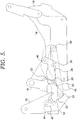
- the front blocker cam 24 and the rear blocker cam 30 rotate from the position shown in FIG. 1 , which illustrates the glider-recliner in the closed position, to the position shown in FIG. 5 , which illustrates the glider recliner in the TV position.
- FIG. 1 the cam surface 28 of front blocker cam 24 and the cam surface 34 of rear blocker cam 30 do not engage the blocker pin 22 on the rear glide link 18.
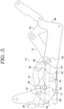
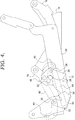
- the glider-recliner can "glide” between a forward-most glide position, shown in FIG. 3 , and a rearward-most glide position, shown in FIG. 4 .
- the blocker pin 22 abuts a rear notched surface 36 on carrier link 20.
- the carrier link 20 is thus prevented from further forward movement by the blocker pin 22 in this position.
- the blocker pin 22 abuts an angled face on carrier link 20.
- the carrier link 20 is thus prevented from further rearward movement by the blocker pin 22 in this position.
- the glider mechanism moves to the TV position (see FIG. 5 )
- the front blocker cam 24 is rotated about pivot point 26, and the rear blocker cam 30 is rotated about pivot point 32. This rotation moves cam surface 28 and cam surface 34 into contact with the blocker pin 22, as best seen in FIG. 5 .
- Rotation of front blocker cam 24 and rear blocker cam 30, in concert with moving from the closed to the TV position, can be achieved in several ways.
- the rotation is driven by movement of a footrest drive link 40 (see FIG. 6 ).
- a blocker control link 42 is pivotably coupled to footrest drive link 40 at pivot point 44.
- Blocker control link 42 extends forwardly and is pivotably coupled near its forward end to front blocker cam 24 at pivot point 46.
- the forward-most end of blocker control link 42 is pivotably coupled to a blocker connector link 48 at pivot point 50.
- the opposite end of blocker connector link 48 is pivotably coupled to rear blocker cam 30 at pivot point 52.
- the footrest drive link 40 moves forwardly, moving the blocker control link 42 forwardly, and driving rotation of front blocker cam 24 about pivot point 26. Additionally, as the footrest drive link 40 drives the blocker control link 42 forwardly, the blocker connector link 48 also moves forwardly, driving rotation of the rear blocker cam 30 about pivot point 32. Therefore, as the glider-recliner moves from the closed position to the TV position, the front blocker cam 24 and the rear blocker cam 30 are rotated in opposite directions. In the TV position ( FIGS. 5 , 8 ), cam surface 28 of front blocker cam 24, and cam surface 34 of rear blocker cam 30 trap the blocker pin 22 on the rear glide link 18, preventing any gliding movement.
- the remainder of the glider-recliner base 10 can be constructed from any of many designs.
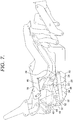
- the remainder of a recline mechanism 54 of glider-recliner base 10 is shown in FIGS. 7-10 and described below. Only one side of glider recliner base 10 is shown in the Figures, for clarity, with the removed side being a mirror-image of the side that is shown.
- the recline mechanism 54 is coupled to a manual or motorized base assembly as would be understood by those of skill in the art.
- the recline mechanism 54 is coupled to the glider-recliner base 10 at one point through a rear pivot link 56 pivotably coupled to carrier link 20 at pivot point 58.
- Rear pivot link 56 has a generally triangular shape, as shown. As best seen in FIG.
- sequence link 64 is pivotably coupled to a rear lift link 66 at pivot point 67, seen in FIG. 10 .
- Sequence link 64 thus extends between rear lift link 66 and rear pivot link 56, and is also coupled to footrest drive link 40.
- the rear lift link 66 is pivotably coupled on its rearward end to rear pivot link 56 at pivot point 68.
- the opposite end of rear lift link 66 is pivotably coupled to a connector link 70 at pivot point 72.
- the rear lift link 66 thus extends between, and is pivotably coupled to, the rear pivot link 56 and the connector link 70.
- a rear back pivot link 74 is pivotably coupled to rear lift link 66 at pivot point 76.
- the rear lift link 66 is also pivotably connected to a seat mounting plate 104 at pivot point 69, as best seen in FIG 9 .
- the travel of rear lift link relative to sear mounting plate 104 is limited by a pin and slot coupling 71.
- rear back pivot link 74 is pivotably coupled to back bracket 78 at pivot point 80.
- the back bracket 78 is shaped as shown, with an upper extending leg that is used to couple the back bracket 78 to a back of the chair.
- the forward, lower area of back bracket 78 is pivotably coupled to an upper end of a forward back pivot link 82 at pivot point 84.
- the lower end of forward back pivot link 82 is pivotably coupled to rear lift link 66 at pivot point 86.
- An alternative coupling of forward back pivot link 82 is shown in FIGS. 15 and 17 , where forward back pivot link 82 is pivotably coupled on its lower end to seat mounting plate 104, at pivot point 86.
- a rearward end of a control link 88 is pivotably coupled to the forward back pivot link 82 at pivot point 90.
- the forward end of control link 88 is pivotably coupled to a front lift link 92 at pivot point 94.
- the front lift link 92 is pivotably coupled on its rear end to the upper end of connector link 70 at pivot point 96 ( FIG. 9 ).
- a forward end of front lift link 92 is pivotably coupled to the upper end of a front pivot link 98 at pivot point 100.
- front lift link 92 is also pivotably coupled to a seat mounting plate 104 at pivot point 106 (see FIG. 10 ).
- the lower end of front pivot link 98 is pivotably coupled to carrier link 20 at pivot point 108.
- footrest drive link 40 extends from the connection to sequence link 64 and rear pivot link 56 forwardly and is pivotably connected on its forward end to a rear ottoman link 110 at pivot point 112.
- Rear ottoman link 110 is pivotably coupled on its upper end to seat mounting plate 104 at pivot point 114.
- the opposite end of rear ottoman link 110 is pivotably coupled to a footrest extension link 116 at pivot point 118 (see FIG. 9 ).
- the end of footrest extension link 116 opposite pivot point 118 is pivotably coupled to a mid-ottoman bracket 120 and pivot point 122.
- footrest extension link 116 is pivotably coupled, generally at a mid-point, to a front ottoman link 124 at pivot point 126.
- Front ottoman link 124 is pivotably coupled on one end to seat mounting plate 104 at pivot point 128 (see FIG. 10 ), and is pivotably coupled on the other end to a wide ottoman link 130 at pivot point 132.
- the wide ottoman link 130 is pivotably coupled on its other end to an ottoman bracket 134 at pivot point 136.
- a mid-point of the mid-ottoman bracket 120 is pivotably coupled to the wide ottoman link 130 at pivot point 138.
- a footrest control link 140 is pivotably coupled on one end to ottoman bracket 134 at pivot point 142, and is pivotably coupled on the other end to mid-ottoman bracket 120 at pivot point 144.
- the ottoman linkage described above can be moved from a closed position in FIGS. 6-7 , to an extended position as shown in FIGS. 8-10 .
- FIGS. 11-14 Another exemplary aspect is shown in FIGS. 11-14 .
- the rotation is again driven by movement of the footrest drive link 40.
- a blocker control link 150 is pivotably coupled to footrest drive link 40 at pivot point 152.
- Blocker control link 150 extends forwardly and is pivotably coupled on its forward end to a blocker connector link 154 at pivot point 156.
- Blocker connector link 154 has an approximate J-shape and is pivotably coupled on one outer end to front blocker cam 24 at pivot point 158 and is pivotably coupled on the other outer end to rear blocker cam 30 at pivot point 160.
- this aspect functions largely as described above.
- the footrest drive link 40 moves forwardly, moving the blocker control link 150 forwardly. This movement also moves the blocker connector link 154 forwardly and upwardly (compare FIG. 11 to FIG. 12 ).
- the blocker connector link 154 drives rotation of front blocker cam 24 about pivot point 26 and the rear blocker cam 30 about pivot point 32. Therefore, as the glider-recliner moves from the closed position to the TV position, the front blocker cam 24 and the rear blocker cam 30 are again rotated in opposite directions. In the TV position, cam surface 28 of front blocker cam 24, and cam surface 34 of rear blocker cam 30 hold the blocker pin 22 on the rear glide link 18, preventing any gliding movement.
- FIGS. 15-19 Another exemplary aspect for implementing rotation of the front and rear blocker cams, in concert with moving from the closed to the TV position, is shown in FIGS. 15-19 .
- the rotation of a front blocker cam 24' is again driven by movement of the footrest drive link 40.
- a front blocker control link 170 is pivotably coupled to footrest drive link 40 at pivot point 172.
- Front blocker control link 170 extends forwardly and is pivotably coupled on its forward end directly to the front blocker cam 24' at pivot point 174.
- a rear blocker control link 176 is pivotably coupled on one end to rear pivot link 56 and pivot point 178, and is pivotably coupled on the other end to a rear blocker cam 30' at pivot point 180.
- front blocker cam 24' and rear blocker cam 30' have slightly different overall shapes so as to properly connect with the front blocker control link 170 and the rear blocker control link 176, respectively.
- this aspect functions as the other embodiments described above, in that front blocker cam 24' and rear blocker cam 30' are caused to rotate in opposite directions as the glider-recliner moves from the closed position to the TV position.
- the footrest drive link 40 moves forwardly, it drives the front blocker control link 170 forwardly, to drive rotation of front blocker cam 24' about pivot point 26.
- the rear pivot link 56 rotates, driving rotation of rear blocker cam 30' about pivot point 32.
- the rear pivot link 56 rotates, and through the connection of the rear blocker control link 176, the rear blocker cam 30' also is returned to the position shown in FIG. 15 , once again allowing gliding movement.
- the blocker linkage described above can be implemented on a motorized glider-recliner or a manual glider-recliner, depending on the desired end use.
- a base and motor are coupled to the glider-recliner linkage.
- An exemplary base and motor structure is shown and described in United States Provisional Patent Application No. 62/368,283, filed on July 29, 2016 , which is hereby incorporated by reference.
Landscapes
- Health & Medical Sciences (AREA)
- Dentistry (AREA)
- General Health & Medical Sciences (AREA)
- Chairs For Special Purposes, Such As Reclining Chairs (AREA)
- Seats For Vehicles (AREA)
Abstract
Description
- This application claims priority to
United States Provisional Patent Application No. 62/368,283, filed on July 29, 2016 - Glider-recliner (glider) chairs are generally well known in the furniture industry. The term glider is used throughout this description to describe articles of furniture that include a reclining mechanism with a glider feature. Gliders are chairs that allow the user to reciprocate back-and-forth in a gliding motion. Gliders are known in both a manual configuration (where the user releases the mechanism from closed to TV, and moves the mechanism from TV to full recline) and a motorized version (where a motor is used to move the mechanism between the various positions).
- The reclining motion is achieved in glider chairs with a linkage mechanism that is coupled to the base and/or to a gliding linkage. The linkage mechanisms found in gliders in the art include a plurality of interconnected links that provide one or more mechanisms for extending a footrest, reclining the chair, and obstructing movements of the chair when in specific orientations. Typically, gliders known in the art provide three positions: an upright seated position with the footrest retracted beneath the chair (the closed position), a television viewing or TV position in which the chair back is slightly reclined but still provides a generally upright position with the footrest extended, and a full-recline position in which the chair back is reclined an additional amount farther than in the TV position but still generally inclined with respect to the seat of the chair and with the foot rest extended. For gliders, the chair is permitted to glide when the mechanism is in the closed position. The mechanism "locks" the glide mechanism to prevent gliding movement when the chair is in the TV or full-recline position.
- Previous mechanisms used to lock the glide mechanism sometimes inadvertently locked the glider, when undesired, or resulted in an abrupt stop, which could be unpleasant to users. It would be desirable to provide a glider (whether manual or powered) having a locking structure that is more reliable and that more-smoothly locks the glider when desired.
- Embodiments of the invention are defined by the claims below, not this summary. A high-level overview of various aspects of the invention are provided here for that reason, to provide an overview of the disclosure, and to introduce a selection of concepts that are further described below in the detailed-description section. This summary is not intended to identify key features or essential features of the claimed subject matter, nor is it intended to be used as an aid in isolation to determine the scope of the claimed subject matter.
- In an aspect of the invention a blocker linkage for use in selectively locking a glider-recliner is provided. The glider-recliner is operable to move between closed, TV and full-recline positions. The blocker linkage includes a glide bracket having a forward end and a rearward end. A top end of a front glide link is pivotably coupled to the forward end of the glide bracket. Similarly, a top end of a rear glide link is pivotably coupled to the rearward end of the glide bracket. The rear glide link has a blocker pin coupled to it that extends outwardly. A carrier link is pivotably coupled to the bottom of the front glide link and pivotably coupled to the bottom of the rear glide link. A rear blocker cam is pivotably coupled to the carrier link. Similarly, a front blocker cam is also pivotably coupled to the carrier link. The rear blocker cam and the front blocker cam are operably coupled to cooperatively engage the blocker pin on the rear glide link when the glider-recliner is moved from the closed position to the TV and full-recline positions, preventing movement of the rear glide link (and thus the gliding movement supported by the carrier link).
- Illustrative embodiments of the invention are described in detail below with reference to the attached drawing figures, and wherein:
-
FIG. 1 is a side view of selected components of an exemplary glider-recliner chair mechanism in a closed position, showing the blocking linkage disengaged, in accordance with an aspect of the invention; -
FIG. 2 is a side view of the other side ofFIG. 1 , showing selected components of an exemplary glider-recliner chair mechanism in a closed position, showing the blocking linkage disengaged, in accordance with an aspect of the invention; -
FIG. 3 is a view similar toFIG. 1 , showing the components in a forward-glide position; -
FIG. 4 is a view similar toFIG. 1 , showing the components in a rearward-glide position; -
FIG. 5 is a side view of the selected components ofFIG. 1 with the glider recliner in the TV position, showing the blocking linkage engaged, in accordance with an aspect of the invention; -
FIG. 6 a side view of one side of the components of an exemplary glider-recliner chair mechanism in a closed position, showing the blocking linkage disengaged, in accordance with an aspect of the invention; -
FIG. 7 is a view similar toFIG. 6 , with certain components shown in dashed lines to reveal other components; -
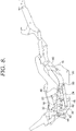
FIG. 8 is a view of the mechanism in the TV position, with certain components shown in dashed lines to reveal other components; -
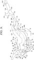
FIG. 9 is a view of the mechanism in the full-recline position with certain components shown in dashed lines to reveal other components; -
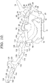
FIG. 10 is a side view similar toFIG. 9 , but from the other side; -
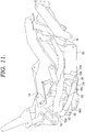
FIG. 11 is a view similar toFIG. 6 , in accordance with an additional aspect of the invention; -
FIG. 12 is a view ofFIG. 11 , with certain components, or portions of components, removed for clarity to reveal other components; -
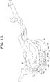
FIG. 13 is a view of the mechanism ofFIG. 11 in the full-recline position; -
FIG. 14 is a view ofFIG. 13 with certain components, or portions of components, removed for clarity to reveal other components; -
FIG. 15 is a view similar toFIG. 6 , in accordance with an additional aspect of the invention; -
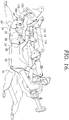
FIG. 16 is a perspective view ofFIG. 15 with certain components, or portions of components, removed, for clarity; -
FIG. 17 is a view of the mechanism ofFIG. 15 in the full-recline position; -
FIG. 18 is a view similar toFIG. 17 with certain components, or portions of components, removed, for clarity; and -
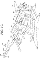
FIG. 19 is a perspective view of the mechanism of claim 17, shown with one side removed for clarity. - The subject matter of aspects of the invention is described with specificity herein to meet statutory requirements. But the description itself is not intended to necessarily limit the scope of claims. Rather, the claimed subject matter might be embodied in other ways to include different steps, components, or combinations thereof, in conjunction with other present or future technologies.
- Referring to the drawings and initially to
FIGS. 1-5 , certain components of a glider-recliner base 10 are shown, in the closed position in accordance with aspects of the invention. The glider-recliner base 10 is more-fully described later, with reference toFIGS. 6-10 . Glider-recliner base 10 includes ablocker linkage 12 that allows a gliding motion when the glider-recliner base 10 is in the closed position, but blocks a gliding motion when the glider-recliner base 10 is in the TV or full-recline positions. Theblocker linkage 12 includes aglide bracket 14 that is typically coupled to a frame supporting the remainder of the mechanism. A top end of afront glide link 16 is pivotably coupled to a front portion ofglide bracket 14, and a top end of arear glide link 18 is pivotably coupled to a rear portion ofglide bracket 14. As best seen inFIG. 2 , the bottom ends offront glide link 16 andrear glide link 18 are pivotably coupled to acarrier link 20. As best seen inFIG. 1 ,rear glide link 18 includes ablocker pin 22, which is rigidly secured to therear glide link 18 generally midway between the top and bottom of therear glide link 18.Carrier link 20 is thus supported onglide bracket 14 byfront glide link 16 andrear glide link 18 such that the carrier link can reciprocate in a back-and-forth motion (gliding) relative to the glide bracket 14 (and thus the supporting frame) when the glider-recliner is in the closed position. - When the glider-recliner is in a closed position, the
carrier link 20 should thus be able to reciprocate in the back-and-forth gliding motion relative to theglide bracket 14. However, when the chair is in the TV or full-recline positions, thecarrier link 20 should be locked in placed relative to theglide bracket 14. To facilitate this locking, afront blocker cam 24 is pivotably coupled tocarrier link 20 atpivot point 26. The front blocker cam rotates clock-wise (as viewed inFIGS. 1 and3-5 ) aboutpivot point 26. The front block cam has acam surface 28, as best seen inFIG. 1 . Similarly, arear blocker cam 30 is pivotably coupled to carrier link 20 atpivot point 32. The rear blocker cam rotates counter-clockwise (as viewed inFIGS. 1 and3-5 ) aboutpivot point 32. Therear blocker cam 30 includes acam surface 34, as best seen inFIG. 1 . - The
front blocker cam 24 and therear blocker cam 30 rotate from the position shown inFIG. 1 , which illustrates the glider-recliner in the closed position, to the position shown inFIG. 5 , which illustrates the glider recliner in the TV position. As can be seen, in the closed position ofFIG. 1 , thecam surface 28 offront blocker cam 24 and thecam surface 34 ofrear blocker cam 30 do not engage theblocker pin 22 on therear glide link 18. In this closed position, the glider-recliner can "glide" between a forward-most glide position, shown inFIG. 3 , and a rearward-most glide position, shown inFIG. 4 . In the forward-most glide position, theblocker pin 22 abuts a rear notchedsurface 36 oncarrier link 20. Thecarrier link 20 is thus prevented from further forward movement by theblocker pin 22 in this position. In the rearward-most glide position, theblocker pin 22 abuts an angled face oncarrier link 20. Thecarrier link 20 is thus prevented from further rearward movement by theblocker pin 22 in this position. As the glider mechanism moves to the TV position (seeFIG. 5 ), thefront blocker cam 24 is rotated aboutpivot point 26, and therear blocker cam 30 is rotated aboutpivot point 32. This rotation movescam surface 28 andcam surface 34 into contact with theblocker pin 22, as best seen inFIG. 5 . - Rotation of
front blocker cam 24 andrear blocker cam 30, in concert with moving from the closed to the TV position, can be achieved in several ways. In a first aspect, as shown inFIGS. 1-10 , the rotation is driven by movement of a footrest drive link 40 (seeFIG. 6 ). In this exemplary aspect, ablocker control link 42 is pivotably coupled tofootrest drive link 40 atpivot point 44.Blocker control link 42 extends forwardly and is pivotably coupled near its forward end tofront blocker cam 24 atpivot point 46. The forward-most end ofblocker control link 42 is pivotably coupled to ablocker connector link 48 atpivot point 50. The opposite end ofblocker connector link 48 is pivotably coupled torear blocker cam 30 atpivot point 52. - As the glider-recliner moves from the closed position to the TV position, the
footrest drive link 40 moves forwardly, moving theblocker control link 42 forwardly, and driving rotation offront blocker cam 24 aboutpivot point 26. Additionally, as thefootrest drive link 40 drives theblocker control link 42 forwardly, theblocker connector link 48 also moves forwardly, driving rotation of therear blocker cam 30 aboutpivot point 32. Therefore, as the glider-recliner moves from the closed position to the TV position, thefront blocker cam 24 and therear blocker cam 30 are rotated in opposite directions. In the TV position (FIGS. 5 ,8 ),cam surface 28 offront blocker cam 24, andcam surface 34 ofrear blocker cam 30 trap theblocker pin 22 on therear glide link 18, preventing any gliding movement. This trapped condition ofblocker pin 22 remains as the glider recliner is moved to the fully-extend position, as shown inFIG. 9 . When the glider-recliner is returned to the closed position, thefootrest drive link 40 moves rearwardly, and through the connections of theblocker control link 42 andblocker connector link 48, thefront blocker cam 24 and therear blocker cam 30 are returned to the position shown inFIG. 7 , once again allowing gliding movement. - The remainder of the glider-
recliner base 10 can be constructed from any of many designs. As one example, the remainder of arecline mechanism 54 of glider-recliner base 10 is shown inFIGS. 7-10 and described below. Only one side ofglider recliner base 10 is shown in the Figures, for clarity, with the removed side being a mirror-image of the side that is shown. Moreover, therecline mechanism 54 is coupled to a manual or motorized base assembly as would be understood by those of skill in the art. Therecline mechanism 54 is coupled to the glider-recliner base 10 at one point through arear pivot link 56 pivotably coupled to carrier link 20 atpivot point 58.Rear pivot link 56 has a generally triangular shape, as shown. As best seen inFIG. 9 , the lower end ofrear pivot link 56 is pivotably coupled to afootrest drive link 40 through a roller 60 that rides within aslot 62 on asequence link 64. The opposite end ofsequence link 64 is pivotably coupled to arear lift link 66 atpivot point 67, seen inFIG. 10 .Sequence link 64 thus extends betweenrear lift link 66 andrear pivot link 56, and is also coupled tofootrest drive link 40. - As best seen in
FIG. 10 , therear lift link 66 is pivotably coupled on its rearward end torear pivot link 56 atpivot point 68. The opposite end ofrear lift link 66 is pivotably coupled to aconnector link 70 atpivot point 72. Therear lift link 66 thus extends between, and is pivotably coupled to, therear pivot link 56 and theconnector link 70. As best seen inFIG. 9 , a rearback pivot link 74 is pivotably coupled torear lift link 66 atpivot point 76. Therear lift link 66 is also pivotably connected to aseat mounting plate 104 atpivot point 69, as best seen inFIG 9 . The travel of rear lift link relative to sear mountingplate 104 is limited by a pin andslot coupling 71. The opposite end of rearback pivot link 74 is pivotably coupled to backbracket 78 atpivot point 80. Theback bracket 78 is shaped as shown, with an upper extending leg that is used to couple theback bracket 78 to a back of the chair. The forward, lower area ofback bracket 78 is pivotably coupled to an upper end of a forwardback pivot link 82 atpivot point 84. The lower end of forward backpivot link 82 is pivotably coupled torear lift link 66 atpivot point 86. An alternative coupling of forward backpivot link 82 is shown inFIGS. 15 and17 , where forward backpivot link 82 is pivotably coupled on its lower end to seat mountingplate 104, atpivot point 86. - As best seen in
FIGS. 9 and10 , a rearward end of acontrol link 88 is pivotably coupled to the forward backpivot link 82 atpivot point 90. The forward end ofcontrol link 88 is pivotably coupled to afront lift link 92 atpivot point 94. Thefront lift link 92 is pivotably coupled on its rear end to the upper end ofconnector link 70 at pivot point 96 (FIG. 9 ). A forward end offront lift link 92 is pivotably coupled to the upper end of afront pivot link 98 atpivot point 100. Belowpivot point 94,front lift link 92 is also pivotably coupled to aseat mounting plate 104 at pivot point 106 (seeFIG. 10 ). The lower end offront pivot link 98 is pivotably coupled to carrier link 20 atpivot point 108. - As best seen in
FIG. 6 ,footrest drive link 40 extends from the connection to sequencelink 64 andrear pivot link 56 forwardly and is pivotably connected on its forward end to arear ottoman link 110 atpivot point 112.Rear ottoman link 110 is pivotably coupled on its upper end to seat mountingplate 104 atpivot point 114. The opposite end ofrear ottoman link 110 is pivotably coupled to a footrest extension link 116 at pivot point 118 (seeFIG. 9 ). The end of footrest extension link 116opposite pivot point 118 is pivotably coupled to amid-ottoman bracket 120 andpivot point 122. Additionally,footrest extension link 116 is pivotably coupled, generally at a mid-point, to afront ottoman link 124 atpivot point 126.Front ottoman link 124 is pivotably coupled on one end to seat mountingplate 104 at pivot point 128 (seeFIG. 10 ), and is pivotably coupled on the other end to awide ottoman link 130 atpivot point 132. Thewide ottoman link 130 is pivotably coupled on its other end to anottoman bracket 134 atpivot point 136. As seen inFIG. 10 , a mid-point of themid-ottoman bracket 120 is pivotably coupled to thewide ottoman link 130 atpivot point 138. Afootrest control link 140 is pivotably coupled on one end toottoman bracket 134 atpivot point 142, and is pivotably coupled on the other end tomid-ottoman bracket 120 atpivot point 144. The ottoman linkage described above can be moved from a closed position inFIGS. 6-7 , to an extended position as shown inFIGS. 8-10 . - As noted above, rotation of
front blocker cam 24 andrear blocker cam 30, in concert with moving from the closed to the TV position, can be achieved in several ways. Another exemplary aspect is shown inFIGS. 11-14 . In this aspect, the rotation is again driven by movement of thefootrest drive link 40. Ablocker control link 150 is pivotably coupled tofootrest drive link 40 atpivot point 152. Blocker control link 150 extends forwardly and is pivotably coupled on its forward end to ablocker connector link 154 atpivot point 156.Blocker connector link 154 has an approximate J-shape and is pivotably coupled on one outer end tofront blocker cam 24 atpivot point 158 and is pivotably coupled on the other outer end torear blocker cam 30 atpivot point 160. Operationally, this aspect functions largely as described above. More specifically, as the glider-recliner moves from the closed position to the TV position, thefootrest drive link 40 moves forwardly, moving theblocker control link 150 forwardly. This movement also moves theblocker connector link 154 forwardly and upwardly (compareFIG. 11 to FIG. 12 ). As theblocker connector link 154 moves it drives rotation offront blocker cam 24 aboutpivot point 26 and therear blocker cam 30 aboutpivot point 32. Therefore, as the glider-recliner moves from the closed position to the TV position, thefront blocker cam 24 and therear blocker cam 30 are again rotated in opposite directions. In the TV position,cam surface 28 offront blocker cam 24, andcam surface 34 ofrear blocker cam 30 hold theblocker pin 22 on therear glide link 18, preventing any gliding movement. This held condition ofblocker pin 22 remains as the glider recliner is moved to the fully-extend position, as shown inFIG. 13 . When the glider-recliner is returned to the closed position, thefootrest drive link 40 moves rearwardly, and through the connections of theblocker control link 150 andblocker connector link 154, thefront blocker cam 24 and therear blocker cam 30 are returned to the position shown inFIG. 11 , once again allowing gliding movement. - Another exemplary aspect for implementing rotation of the front and rear blocker cams, in concert with moving from the closed to the TV position, is shown in
FIGS. 15-19 . In this aspect, the rotation of a front blocker cam 24' is again driven by movement of thefootrest drive link 40. More specifically, a frontblocker control link 170 is pivotably coupled tofootrest drive link 40 atpivot point 172. Frontblocker control link 170 extends forwardly and is pivotably coupled on its forward end directly to the front blocker cam 24' atpivot point 174. A rearblocker control link 176 is pivotably coupled on one end torear pivot link 56 andpivot point 178, and is pivotably coupled on the other end to a rear blocker cam 30' atpivot point 180. In this aspect, front blocker cam 24' and rear blocker cam 30' have slightly different overall shapes so as to properly connect with the frontblocker control link 170 and the rearblocker control link 176, respectively. Operationally, this aspect functions as the other embodiments described above, in that front blocker cam 24' and rear blocker cam 30' are caused to rotate in opposite directions as the glider-recliner moves from the closed position to the TV position. In this aspect however, as thefootrest drive link 40 moves forwardly, it drives the frontblocker control link 170 forwardly, to drive rotation of front blocker cam 24' aboutpivot point 26. As the glider-recliner moves from the closed position to the TV position, therear pivot link 56 rotates, driving rotation of rear blocker cam 30' aboutpivot point 32. Therefore, as the glider-recliner moves from the closed position to the TV position, the front blocker cam 24' and the rear blocker cam 30' are again rotated in opposite directions. In the TV position,cam surface 28 of front blocker cam 24', andcam surface 34 of rear blocker cam 30' hold theblocker pin 22 on therear glide link 18, preventing any gliding movement. This held condition ofblocker pin 22 remains as the glider recliner is moved to the fully-extend position, as shown inFIG. 19 . When the glider-recliner is returned to the closed position, thefootrest drive link 40 moves rearwardly, and through the connections of the frontblocker control link 170, the front blocker cam 24' is returned to the position shown inFIG. 15 . As the glider-recliner is returned to the closed position, therear pivot link 56 rotates, and through the connection of the rearblocker control link 176, the rear blocker cam 30' also is returned to the position shown inFIG. 15 , once again allowing gliding movement. - The blocker linkage described above can be implemented on a motorized glider-recliner or a manual glider-recliner, depending on the desired end use. As would be understood by those of skill in the art, in a motorized version, such as shown in
FIG. 19 , a base and motor are coupled to the glider-recliner linkage. An exemplary base and motor structure is shown and described inUnited States Provisional Patent Application No. 62/368,283, filed on July 29, 2016 - Many different arrangements of the various components depicted, as well as components not shown, are possible without departing from the scope of the claims below. Embodiments of the technology have been described with the intent to be illustrative rather than restrictive. Alternative embodiments will become apparent to readers of this disclosure after and because of reading it. Alternative means of implementing the aforementioned can be completed without departing from the scope of the claims below. Certain features and subcombinations are of utility and may be employed without reference to other features and subcombinations and are contemplated within the scope of the claims.
Claims (16)
- A blocker linkage for use in selectively locking a glider-recliner, the glider-recliner operable to move between closed, TV and full-recline positions, the blocker linkage comprising:a glide bracket having a forward end and a rearward end;a front glide link having a top end and a bottom end, the top end being pivotably coupled to the forward end of the glide bracket;a rear glide link having a top end and a bottom end, the top end being pivotably coupled to the rearward end of the glide bracket;a blocker pin coupled to the rear glide link;a carrier link pivotably coupled to the bottom of the front glide link and pivotably coupled to the bottom of the rear glide link;a rear blocker cam pivotably coupled to the carrier link; anda front blocker cam pivotably coupled to the carrier link,wherein the rear blocker cam and the front blocker cam are operably coupled to cooperatively engage the blocker pin and prevent movement of the rear glide link when the glider-recliner is moved to the TV and full-recline positions.
- The blocker linkage of claim 1, further comprising:a footrest drive link that moves as the glider-recliner moves between closed, TV and full-recline positions;a blocker control link pivotably coupled to the footrest drive link and pivotably coupled to the front blocker cam,wherein movement from the closed position to the TV position moves the footrest drive link, which moves the blocker control link to effect rotation of the front blocker cam from a position disengaged from the blocker pin when the glider-recliner is in the closed position to a positioned engaged with the blocker pin when the glider-recliner is in the TV position.
- The blocker linkage of claim 2, further comprising:a blocker connector link pivotably coupled on one end to the blocker control link and pivotably coupled on the other end to the rear blocker cam, such that movement of the blocker control link effects a corresponding movement of the blocker connector link to effect rotation of the rear blocker cam from a position disengaged from the blocker pin when the glider-recliner is in the closed position to a positioned engaged with the blocker pin when the glider-recliner is in the TV position.
- The blocker linkage of claim 1, wherein the front blocker cam has a cam surface configured to engage the blocker pin, and wherein the rear blocker cam has a cam surface configured to engage the blocker pin.
- The blocker linkage of claim 3, wherein the coupling of the blocker control link and the front blocker cam results in the front blocker cam rotating in a first direction as the glider-recliner moves from the closed position to the TV position, and wherein the coupling of the blocker connector link and the rear blocker cam results in the rear blocker cam rotating in a second direction as the glider-recliner moves from the closed position to the TV position.
- The blocker linkage of claim 1, further comprising:a footrest drive link that moves as the glider-recliner moves between closed, TV and full-recline positions;a blocker control link having a first end and a second end, the first end pivotably coupled the footrest drive link; anda blocker connector link pivotably coupled to the blocker control link, and pivotably coupled to the front blocker cam and to the rear blocker cam, such that movement of the blocker control link effects a corresponding movement of the blocker connector link to effect rotation of the front blocker cam and the rear blocker cam from positions disengaged from the blocker pin when the glider-recliner is in the closed position to positions engaged with the blocker pin when the glider-recliner is in the TV position.
- The blocker control linkage of claim 6, wherein the coupling of the blocker control link, the blocker connector link and the front blocker cam and rear blocker cam results in the front blocker cam rotating in a first direction as the glider-recliner moves from the closed position to the TV position, and the rear blocker cam rotating in a second direction as the glider-recliner moves from the closed position to the TV position.
- The blocker control linkage of claim 1, further comprising:a footrest drive link that moves as the glider-recliner moves between closed, TV and full-recline positions;a rear pivot link pivotably coupled to the footrest drive link;a front blocker control link pivotably coupled to the footrest drive link and pivotably coupled to the front blocker cam, the front blocker control link driven by the footrest drive link to effect rotation of the front blocker cam from a position disengaged from the blocker pin when the glider-recliner is in the closed position to a position engaged with the blocker pin when the glider-recliner is in the TV position; anda rear blocker control link pivotably coupled to the rear pivot link and pivotably coupled to the rear blocker cam, the rear blocker control link driven by the rear pivot link to effect rotation of the rear blocker cam from a position disengaged from the blocker pin when the glider-recliner is in the closed position to a position engaged with the blocker pin when the glider-recliner is in the TV position.
- A blocker linkage for use in selectively locking a glider-recliner, the glider-recliner operable to move between closed, TV and full-recline positions, the blocker linkage comprising:a glide bracket having a forward end and a rearward end;a front glide link having a top end and a bottom end, the top end being pivotably coupled to the forward end of the glide bracket;a rear glide link having a top end and a bottom end, the top end being pivotably coupled to the rearward end of the glide bracket, the rear glide link further having a blocker pin extending outwardly and located between the top end and the bottom end;a carrier link pivotably coupled to the bottom of the front glide link and pivotably coupled to the bottom of the rear glide link;a rear blocker cam pivotably coupled to the carrier link;a front blocker cam pivotably coupled to the carrier link; anda cam linkage operable to rotate the rear blocker cam in a first direction, and the front blocker cam in a second direction as the glider-recliner is moved from the closed to the TV position, such that the rear blocker cam and the front blocker cam cooperatively engage the blocker pin and prevent movement of the rear glide link.
- The blocker linkage of claim 9, wherein the cam linkage comprises:a footrest drive link that moves as the glider-recliner moves between closed, TV and full-recline positions;a blocker control link pivotably coupled to the footrest drive link and pivotably coupled to the front blocker cam; anda blocker connector link pivotably coupled on one end to the blocker control link and pivotably coupled on the other end to the rear blocker cam.
- The blocker linkage of claim 9, wherein the front blocker cam has a cam surface configured to engage the blocker pin, and wherein the rear blocker cam has a cam surface configured to engage the blocker pin.
- The blocker linkage of claim 9, further comprising:a footrest drive link that moves as the glider-recliner moves between closed, TV and full-recline positions;a blocker control link having a first end and a second end, the first end pivotably coupled the footrest drive link; anda blocker connector link pivotably coupled to the blocker control link, and pivotably coupled to the front blocker cam and to the rear blocker cam, such that movement of the blocker control link effects a corresponding movement of the blocker connector link to effect rotation of the front blocker cam and the rear blocker cam from positions disengaged from the blocker pin when the glider-recliner is in the closed position to a positions engaged with the blocker pin when the glider-recliner is in the TV position.
- The blocker linkage of claim 9, further comprising:a footrest drive link that moves as the glider-recliner moves between closed, TV and full-recline positions;a rear pivot link pivotably coupled to the footrest drive link;a front blocker control link pivotably coupled to the footrest drive link and pivotably coupled to the front blocker cam, the front blocker control link driven by the footrest drive link to effect rotation of the front blocker cam from a position disengaged from the blocker pin when the glider-recliner is in the closed position to a position engaged with the blocker pin when the glider-recliner is in the TV position; anda rear blocker control link pivotably coupled to the rear pivot link and pivotably coupled to the rear blocker cam, the rear blocker control link driven by the rear pivot link to effect rotation of the rear blocker cam from a position disengaged from the blocker pin when the glider-recliner is in the closed position to a position engaged with the blocker pin when the glider-recliner is in the TV position.
- A glider-recliner linkage operable to move between closed, TV and full-recline positions having a blocker linkage for use in selectively preventing gliding movement when the glider-recliner moves from the closed position to the TV and full-recline positions, the glider-recliner linkage comprising:a glide bracket having a forward end and a rearward end;a front glide link having a top end and a bottom end, the top end being pivotably coupled to the forward end of the glide bracket;a rear glide link having a top end and a bottom end, the top end being pivotably coupled to the rearward end of the glide bracket, the rear glide link further having a blocker pin extending outwardly and located between the top end and the bottom end;a carrier link pivotably coupled to the bottom of the front glide link and pivotably coupled to the bottom of the rear glide link;a rear blocker cam pivotably coupled to the carrier link;a front blocker cam pivotably coupled to the carrier link;a recline linkage operable to move the glider-recliner to and from the closed, TV and full-recline positions; anda cam linkage coupled to the recline linkage operable to rotate the rear blocker cam in a first direction, and the front blocker cam in a second direction as the recline linkage moves the glider-recliner from the closed to the TV position, such that the rear blocker cam and the front blocker cam cooperatively engage the blocker pin and prevent movement of the rear glide link.
- The glide-recliner linkage of claim 14, wherein the cam linkage comprises:a footrest drive link that moves as the glider-recliner moves between closed, TV and full-recline positions;a rear pivot link pivotably coupled to the footrest drive link;a front blocker control link pivotably coupled to the footrest drive link and pivotably coupled to the front blocker cam, the front blocker control link driven by the footrest drive link to effect rotation of the front blocker cam from a position disengaged from the blocker pin when the glider-recliner is in the closed position to a position engaged with the blocker pin when the glider-recliner is in the TV position; anda rear blocker control link pivotably coupled to the rear pivot link and pivotably coupled to the rear blocker cam, the rear blocker control link driven by the rear pivot link to effect rotation of the rear blocker cam from a position disengaged from the blocker pin when the glider-recliner is in the closed position to a position engaged with the blocker pin when the glider-recliner is in the TV position.
- The blocker linkage of claim 15, wherein the front blocker cam has a cam surface configured to engage the blocker pin, and wherein the rear blocker cam has a cam surface configured to engage the blocker pin.
Applications Claiming Priority (2)
| Application Number | Priority Date | Filing Date | Title |
|---|---|---|---|
| US201662368283P | 2016-07-29 | 2016-07-29 | |
| US15/485,711 US10104966B2 (en) | 2016-07-29 | 2017-04-12 | Glider recline linkage with double blocker cams |
Publications (2)
| Publication Number | Publication Date |
|---|---|
| EP3275340A2 true EP3275340A2 (en) | 2018-01-31 |
| EP3275340A3 EP3275340A3 (en) | 2018-03-21 |
Family
ID=59384042
Family Applications (1)
| Application Number | Title | Priority Date | Filing Date |
|---|---|---|---|
| EP17182541.7A Withdrawn EP3275340A3 (en) | 2016-07-29 | 2017-07-21 | Glider recline linkage with double blocker cams |
Country Status (4)
| Country | Link |
|---|---|
| US (1) | US10104966B2 (en) |
| EP (1) | EP3275340A3 (en) |
| CN (1) | CN107660911B (en) |
| CA (1) | CA2974130C (en) |
Families Citing this family (13)
| Publication number | Priority date | Publication date | Assignee | Title |
|---|---|---|---|---|
| CN107232857B (en) * | 2017-08-03 | 2023-08-25 | 浙江飞力科技有限公司 | Footrest extension device for movable sofa |
| CN108634836B (en) * | 2018-05-09 | 2024-10-11 | 福建西河卫浴科技有限公司 | Blocker, connector, plug assembly, prefabricated part, plug structure and shower room |
| US10779652B2 (en) * | 2018-12-19 | 2020-09-22 | Ko-Po Chen | Swingable body carrier |
| US10932570B2 (en) * | 2019-05-20 | 2021-03-02 | L&P Property Management Company | Zero-wall clearance linkage mechanism with power seat drive |
| US10842274B1 (en) * | 2019-05-20 | 2020-11-24 | L&P Property Management Company | Zero-wall clearance linkage mechanism with power seat drive |
| CN111000391A (en) * | 2019-12-13 | 2020-04-14 | 北京电子工程总体研究所 | Distributed chair seat with configurable stress points |
| CN214284112U (en) * | 2020-08-07 | 2021-09-28 | 张孝兆 | Bracket extension device, frame body with same and chair |
| EP4340679A4 (en) * | 2021-05-17 | 2025-07-16 | Remacro Mach & Tech Wujiang Co Ltd | MECHANICAL EXTENSION DEVICE FOR EXTENDABLE SEAT AND EXTENDABLE SEAT |
| CN113892772A (en) * | 2021-10-27 | 2022-01-07 | 锐迈机械科技(吴江)有限公司 | Mechanical extension for movable seating unit and seating unit |
| US12082698B2 (en) * | 2022-07-29 | 2024-09-10 | Motomotion China Corporation | Mechanism for zero-gravity reclining chair |
| CN115606959B (en) * | 2022-08-23 | 2024-05-24 | 顾家家居股份有限公司 | Zero back rubbing compact sofa iron frame structure |
| USD1059103S1 (en) | 2022-09-15 | 2025-01-28 | Smith System Manufacturing Company | Chair |
| US20250380805A1 (en) * | 2024-06-17 | 2025-12-18 | L&P Property Management Company | Glider recliner mechanism and chair with increased seat pitch |
Family Cites Families (27)
| Publication number | Priority date | Publication date | Assignee | Title |
|---|---|---|---|---|
| FR1255403A (en) | 1960-01-25 | 1961-03-10 | Convertible armchair | |
| US4071275A (en) | 1976-03-22 | 1978-01-31 | Royal Development Company, Inc. | Recliner chair with wall avoiding action |
| US4131316A (en) * | 1976-07-02 | 1978-12-26 | H. R. Turner (Willenhall) Limited | Vehicle seats |
| US4194783A (en) * | 1977-03-28 | 1980-03-25 | Mohasco Corporation | Wall proximity chairs and hardware therefor |
| US4108491A (en) | 1977-04-22 | 1978-08-22 | Royal Development Company, Inc. | Wall-avoiding recliner chair |
| US4591205A (en) * | 1983-11-04 | 1986-05-27 | Leggett & Platt, Incorporated | Glider recliner |
| US4707025A (en) * | 1986-06-26 | 1987-11-17 | Parma Corporation | Rocker recliner |
| US5795021A (en) * | 1995-10-10 | 1998-08-18 | Rogers; W. Clark | Gliding reclining chair |
| AU7436396A (en) * | 1995-10-18 | 1997-05-07 | La-Z-Boy Incorporated | Glider chair |
| EP1121264B1 (en) * | 1998-10-13 | 2003-09-10 | Magna Seating Systems Inc. | Seat cushion height adjustment assembly |
| US6637813B2 (en) * | 1999-04-23 | 2003-10-28 | L&P Property Management Company | Reclining mechanism and furniture item having pusher mechanism |
| US7497512B2 (en) * | 2005-05-23 | 2009-03-03 | L & P Property Management Company | Recliner drive mechanism for a rocker chair |
| CN2922646Y (en) * | 2006-06-20 | 2007-07-18 | 明门实业股份有限公司 | Seat group with adjustable backrest |
| US8016348B2 (en) * | 2008-11-24 | 2011-09-13 | Ultra-Mek, Inc. | Reciprocating seating unit with power actuator |
| US8113574B2 (en) * | 2008-11-24 | 2012-02-14 | Ultra-Mek, Inc. | Rocking-reclining seating unit with power actuator |
| US8398165B2 (en) * | 2010-01-15 | 2013-03-19 | L & P Property Management Company | Powered rocker recliner linkage mechanism |
| US8449027B2 (en) * | 2010-03-23 | 2013-05-28 | L & P Property Management Company | Full-flat recline linkage |
| US8398169B2 (en) * | 2010-04-13 | 2013-03-19 | La-Z-Boy Incorporated | Furniture member having powered gliding motion |
| US8833844B2 (en) * | 2010-04-13 | 2014-09-16 | La-Z-Boy Incorporated | Power actuated glider furniture member |
| US8523218B2 (en) * | 2010-08-09 | 2013-09-03 | Europe Brands S.A.R.L. | Stroller with articulating structure |
| US8616627B2 (en) * | 2010-11-08 | 2013-12-31 | Ultra-Mek, Inc. | Gliding-reclining seating unit |
| US8517463B2 (en) * | 2010-11-09 | 2013-08-27 | Ultra-Mek, Inc. | Gliding-reclining layflat seating unit with power actuator and manual and automatic locking linkages |
| US8915544B2 (en) * | 2011-08-26 | 2014-12-23 | La-Z-Boy Incorporated | Furniture member with mechanism for powered occupant lift |
| US9149121B2 (en) * | 2012-02-06 | 2015-10-06 | Ultra-Mek, Inc. | Gliding-reclining seating unit actuated by pushing on the arms |
| JP6089848B2 (en) * | 2013-03-22 | 2017-03-08 | アイシン精機株式会社 | Vehicle seat reclining device |
| US9603452B2 (en) * | 2014-10-14 | 2017-03-28 | Ultra-Mek, Inc. | Gliding-reclining seating unit with power actuators |
| US10383442B2 (en) * | 2017-02-28 | 2019-08-20 | L&P Property Management Company | Stop mechanism for recliner chair |
-
2017
- 2017-04-12 US US15/485,711 patent/US10104966B2/en active Active
- 2017-07-20 CA CA2974130A patent/CA2974130C/en active Active
- 2017-07-21 EP EP17182541.7A patent/EP3275340A3/en not_active Withdrawn
- 2017-07-28 CN CN201710629355.0A patent/CN107660911B/en active Active
Also Published As
| Publication number | Publication date |
|---|---|
| CA2974130C (en) | 2020-05-12 |
| CN107660911B (en) | 2021-10-01 |
| CN107660911A (en) | 2018-02-06 |
| EP3275340A3 (en) | 2018-03-21 |
| US10104966B2 (en) | 2018-10-23 |
| CA2974130A1 (en) | 2018-01-29 |
| US20180027965A1 (en) | 2018-02-01 |
Similar Documents
| Publication | Publication Date | Title |
|---|---|---|
| US10104966B2 (en) | Glider recline linkage with double blocker cams | |
| US11266245B2 (en) | Rocker/glider recliner linkage with projected back pivot point | |
| CN107660913B (en) | Rocking chair or slide chair linkage with protruding backrest pivot point | |
| US7497512B2 (en) | Recliner drive mechanism for a rocker chair | |
| US8616626B2 (en) | Linkage mechanism for a high-leg seating unit | |
| US6793279B2 (en) | Reclining seating unit movable to heart-rest position | |
| US6659556B2 (en) | Reclining motorized multi-position chair with rocking and pivoting action | |
| EP3171734B1 (en) | Zero-wall clearance linkage mechanism with power seat drive | |
| US20080001442A1 (en) | Linkage mechanism for a recliner chair | |
| US9962004B2 (en) | Profile ottoman linkage | |
| US20060061147A1 (en) | Linkage mechanism for use in motion furniture | |
| US10743667B2 (en) | Chair back tilt mechanism | |
| MX2012008659A (en) | Zero-wall clearance linkage mechanism for high-leg seating unit. | |
| WO2018160263A1 (en) | Stop mechanism for recliner chair | |
| MX2012010965A (en) | Full-flat recline linkage. | |
| US9351576B1 (en) | Ottoman linkage mechanism with closing assist | |
| EP2808001B1 (en) | Seating device with rising aid | |
| CN222777131U (en) | Movable seat unit and mechanical stretching device thereof |
Legal Events
| Date | Code | Title | Description |
|---|---|---|---|
| PUAI | Public reference made under article 153(3) epc to a published international application that has entered the european phase |
Free format text: ORIGINAL CODE: 0009012 |
|
| AK | Designated contracting states |
Kind code of ref document: A2 Designated state(s): AL AT BE BG CH CY CZ DE DK EE ES FI FR GB GR HR HU IE IS IT LI LT LU LV MC MK MT NL NO PL PT RO RS SE SI SK SM TR |
|
| AX | Request for extension of the european patent |
Extension state: BA ME |
|
| PUAL | Search report despatched |
Free format text: ORIGINAL CODE: 0009013 |
|
| AK | Designated contracting states |
Kind code of ref document: A3 Designated state(s): AL AT BE BG CH CY CZ DE DK EE ES FI FR GB GR HR HU IE IS IT LI LT LU LV MC MK MT NL NO PL PT RO RS SE SI SK SM TR |
|
| AX | Request for extension of the european patent |
Extension state: BA ME |
|
| RIC1 | Information provided on ipc code assigned before grant |
Ipc: A47C 1/034 20060101AFI20180213BHEP |
|
| 17P | Request for examination filed |
Effective date: 20180914 |
|
| RBV | Designated contracting states (corrected) |
Designated state(s): AL AT BE BG CH CY CZ DE DK EE ES FI FR GB GR HR HU IE IS IT LI LT LU LV MC MK MT NL NO PL PT RO RS SE SI SK SM TR |
|
| GRAP | Despatch of communication of intention to grant a patent |
Free format text: ORIGINAL CODE: EPIDOSNIGR1 |
|
| INTG | Intention to grant announced |
Effective date: 20181113 |
|
| STAA | Information on the status of an ep patent application or granted ep patent |
Free format text: STATUS: THE APPLICATION IS DEEMED TO BE WITHDRAWN |
|
| 18D | Application deemed to be withdrawn |
Effective date: 20190326 |