EP3274744B1 - Variable focus lens - Google Patents
Variable focus lens Download PDFInfo
- Publication number
- EP3274744B1 EP3274744B1 EP16717568.6A EP16717568A EP3274744B1 EP 3274744 B1 EP3274744 B1 EP 3274744B1 EP 16717568 A EP16717568 A EP 16717568A EP 3274744 B1 EP3274744 B1 EP 3274744B1
- Authority
- EP
- European Patent Office
- Prior art keywords
- ring
- container
- lens
- thread
- axial direction
- Prior art date
- Legal status (The legal status is an assumption and is not a legal conclusion. Google has not performed a legal analysis and makes no representation as to the accuracy of the status listed.)
- Active
Links
Images


Classifications
-
- G—PHYSICS
- G02—OPTICS
- G02B—OPTICAL ELEMENTS, SYSTEMS OR APPARATUS
- G02B3/00—Simple or compound lenses
- G02B3/12—Fluid-filled or evacuated lenses
- G02B3/14—Fluid-filled or evacuated lenses of variable focal length
-
- G—PHYSICS
- G02—OPTICS
- G02B—OPTICAL ELEMENTS, SYSTEMS OR APPARATUS
- G02B26/00—Optical devices or arrangements for the control of light using movable or deformable optical elements
- G02B26/004—Optical devices or arrangements for the control of light using movable or deformable optical elements based on a displacement or a deformation of a fluid
- G02B26/005—Optical devices or arrangements for the control of light using movable or deformable optical elements based on a displacement or a deformation of a fluid based on electrowetting
-
- G—PHYSICS
- G02—OPTICS
- G02B—OPTICAL ELEMENTS, SYSTEMS OR APPARATUS
- G02B7/00—Mountings, adjusting means, or light-tight connections, for optical elements
- G02B7/02—Mountings, adjusting means, or light-tight connections, for optical elements for lenses
- G02B7/04—Mountings, adjusting means, or light-tight connections, for optical elements for lenses with mechanism for focusing or varying magnification
- G02B7/10—Mountings, adjusting means, or light-tight connections, for optical elements for lenses with mechanism for focusing or varying magnification by relative axial movement of several lenses, e.g. of varifocal objective lens
-
- G—PHYSICS
- G02—OPTICS
- G02B—OPTICAL ELEMENTS, SYSTEMS OR APPARATUS
- G02B7/00—Mountings, adjusting means, or light-tight connections, for optical elements
- G02B7/18—Mountings, adjusting means, or light-tight connections, for optical elements for prisms; for mirrors
- G02B7/182—Mountings, adjusting means, or light-tight connections, for optical elements for prisms; for mirrors for mirrors
-
- A—HUMAN NECESSITIES
- A61—MEDICAL OR VETERINARY SCIENCE; HYGIENE
- A61B—DIAGNOSIS; SURGERY; IDENTIFICATION
- A61B1/00—Instruments for performing medical examinations of the interior of cavities or tubes of the body by visual or photographical inspection, e.g. endoscopes; Illuminating arrangements therefor
- A61B1/00163—Optical arrangements
- A61B1/00188—Optical arrangements with focusing or zooming features
- A61B1/0019—Optical arrangements with focusing or zooming features characterised by variable lenses
-
- G—PHYSICS
- G02—OPTICS
- G02C—SPECTACLES; SUNGLASSES OR GOGGLES INSOFAR AS THEY HAVE THE SAME FEATURES AS SPECTACLES; CONTACT LENSES
- G02C7/00—Optical parts
- G02C7/02—Lenses; Lens systems ; Methods of designing lenses
- G02C7/08—Auxiliary lenses; Arrangements for varying focal length
- G02C7/081—Ophthalmic lenses with variable focal length
- G02C7/085—Fluid-filled lenses, e.g. electro-wetting lenses
Definitions
- the invention relates to a precise mechanically tunable adaptive fluid or liquid lens, with improved mechanical characteristics, namely with reduced mechanical friction and torque effects during tuning procedures and reduced mechanical play for improvements in optical repeatability and accuracy.
- the use of the lens according to the invention is very versatile and further includes without limitation devices such as: vision systems, ophthalmic lenses, ophthalmology equipment such as phoropter, refractometer, fundus cameras, ppt. biometrie, perimeter, tonometer, anomaloscope, contrastometer, endothelmicroscope, anomaloscope, binoptometer, OCT, rodatest, ophthalmoscope, RTA, slitlamp microscope, surgical microscope, auto-refractometer, keratograph, confocal imager, Scheimpflug camera, wavefront aberrometer, pupillometer, skin laser, eye laser, otoscope, laryngoscope, Raman spectrometer, portable spectrometer, photodynamic diagnosis; as well as lighting devices, Lighting fixtures , devices for machine vision, laser processing devices, devices for conducting a light show, printers, metrology devices, (e.g.
- head-worn glasses medical devices, robot cams, motion tracking devices, microscopes, telescopes, endoscopes, binoculars, surveillance cameras, automotive devices, projectors, ophthalmic lenses, range finder, bar code readers, and web cams, fiber coupling, biometric devices, electronic magnifiers, motion tracking, intra-ocular lenses, mobile phones, military, digital still cameras, web cams, microscopes, telescopes, endoscopes, binoculars, research, industrial applications.
- a lens of this basic functionality is shown in US 8000022 .
- the lens consists out of an inner, at least partially deformable optical lens container element which changes its shape upon applying a force to its deformable element.
- the force is created by an external actuator which can be an electronic actuator, such as electromotors or piezoactuators, but also thermal actuators, hydraulic actuators or an operator's hand or others.
- the force is transferred through a mechanical system which typically from a rotatory movement translates to a linear movement, typically perpendicular to the rotary movement. That linear movement is particularly used to move either a ring element or the lens container and transfers force to the elastic optical element.
- the applied force deforms the elastic element and the fluid or elastic lens body changes its optical properties, namely its focal length.
- Further variable focus lens systems are known from US 2010/232161 A1 and US 2011/007161 A1 .
- the problem underlying the present invention is to provide an improved variable focus lens.
- variable focus lens i.e. a lens that comprises an adjustable focal length
- a lens that comprises an adjustable focal length that comprises an elastically deformable optical element and a circumferential mechanism that is configured to transfer (or convert) a rotational movement to an axial movement in an axial direction
- said mechanism comprises a ball bearing system, particularly in order to reduce mechanical friction, friction variation, and particularly in order to improve force-direction dependent positioning insensitivity.
- the movement transfer mechanism of the present disclosure may also be applied to an adaptive mirror.
- the container element may form a mirror that can be adapted (e.g. according to the principles described herein).
- the container ring comprises an outer thread (facing outwards) that engages with the helical thread so that the container element is moved axially in the axial direction when the thread ring is rotated about the axial direction, wherein a lens shaping element that protrudes from the fixed element can be configured to press against the membrane depending on the axial position of the container element with respect to the fixed element/lens shaper so that a curvature of the membrane and therewith the focal length of the lens is adjustable by said axial movement of the container element.
- the spring element is configured to push said rings apart in a way that the axial contact to the thread ring is maintained always on the same side on the helical thread.
- the second ring may form a lock nut while the first ring may be fixed (or integrally connected) to a lateral circumferential wall of the container element to which the membrane and the cover element are fixed to enclose said volume of the container element in which the fluid or liquid resides.
- each vertical post extends through associated through holes formed in the first and the second ring as well as in the annular spring element, wherein for each post the respective through holes are arranged on top of each other in the axial direction.
- the container ring 5a is made out of one or more components 2, 3, 5c, 8, where at least one of it, e.g. a first ring or nut 2 which may surround the lateral wall 5c and can be fixed to the lateral wall 5c and which comprises an outer thread 14a that engages with the helical thread 14 is in mechanical contact to the fixed element 1.
- the interface is acting as axial guidance 19 to allow for precise positioning and block the lens container element 5 from rotation with the thread ring 10.
- This axial guidance 19 preferably consists out of one or more, but typically three vertical posts 19a which are part of the fixed element 1 and the according through-hole(s) 5b in the lens container ring 5a (e.g.
- the axial guidance can be arranged in a linear ball bearing design to reduce the friction to a minimum.
- the interface to the thread ring 10 is particularly optimized in a manner that the system, throughout its complete optical tuning range does not show any kind of mechanical play or hysteresis. This functionality is created by the introduction of one or several elastic elements 8 which introduce a mechanical preload.
- the spring element 8 can be a spiral spring, leaf spring, volute spring, disc spring, azimuth disc spring, elastomer spring, rubber spring or other elements with comparable function. Furthermore, by not only adding an axial load on the spring 8 but also a rotational preload, in particular when using a spiral spring, the mechanical play between the axial guidance 19 and the lower 3 and upper ring 2 can be reduced as both the lower and upper rings 3, 2 are in lateral contact with the axial guidance 19. To further reduce the mechanical friction, it is also possible to add a ball bearing to the helical structure, such as a ball screw system.
Landscapes
- Physics & Mathematics (AREA)
- General Physics & Mathematics (AREA)
- Optics & Photonics (AREA)
- Lens Barrels (AREA)
Description
- The invention relates to a precise mechanically tunable adaptive fluid or liquid lens, with improved mechanical characteristics, namely with reduced mechanical friction and torque effects during tuning procedures and reduced mechanical play for improvements in optical repeatability and accuracy.
- The use of the lens according to the invention is very versatile and further includes without limitation devices such as: vision systems, ophthalmic lenses, ophthalmology equipment such as phoropter, refractometer, fundus cameras, ppt. biometrie, perimeter, tonometer, anomaloscope, contrastometer, endothelmicroscope, anomaloscope, binoptometer, OCT, rodatest, ophthalmoscope, RTA, slitlamp microscope, surgical microscope, auto-refractometer, keratograph, confocal imager, Scheimpflug camera, wavefront aberrometer, pupillometer, skin laser, eye laser, otoscope, laryngoscope, Raman spectrometer, portable spectrometer, photodynamic diagnosis; as well as lighting devices, Lighting fixtures , devices for machine vision, laser processing devices, devices for conducting a light show, printers, metrology devices, (e.g. head-worn) glasses, medical devices, robot cams, motion tracking devices, microscopes, telescopes, endoscopes, binoculars, surveillance cameras, automotive devices, projectors, ophthalmic lenses, range finder, bar code readers, and web cams, fiber coupling, biometric devices, electronic magnifiers, motion tracking, intra-ocular lenses, mobile phones, military, digital still cameras, web cams, microscopes, telescopes, endoscopes, binoculars, research, industrial applications.
- A lens of this basic functionality is shown in
US 8000022 . The lens consists out of an inner, at least partially deformable optical lens container element which changes its shape upon applying a force to its deformable element. The force is created by an external actuator which can be an electronic actuator, such as electromotors or piezoactuators, but also thermal actuators, hydraulic actuators or an operator's hand or others. The force is transferred through a mechanical system which typically from a rotatory movement translates to a linear movement, typically perpendicular to the rotary movement. That linear movement is particularly used to move either a ring element or the lens container and transfers force to the elastic optical element. The applied force deforms the elastic element and the fluid or elastic lens body changes its optical properties, namely its focal length. Further variable focus lens systems are known fromUS 2010/232161 A1 andUS 2011/007161 A1 . - Based on the prior art, the problem underlying the present invention is to provide an improved variable focus lens.
- This problem is solved by the lens according to
claim 1. Preferred embodiments are stated in the sub claims and are further described below. - According to
claim 1, a variable focus lens is disclosed (i.e. a lens that comprises an adjustable focal length) that comprises an elastically deformable optical element and a circumferential mechanism that is configured to transfer (or convert) a rotational movement to an axial movement in an axial direction, wherein said mechanism comprises a ball bearing system, particularly in order to reduce mechanical friction, friction variation, and particularly in order to improve force-direction dependent positioning insensitivity. Further, the variable focus lens comprises an outer thread ring with a helical thread, which thread ring is supported on a fixed element via a ball bearing comprised by the ball bearing system so that the thread ring is rotatable with respect to the fixed element about the axial direction, wherein the lens comprises at least one ring-shaped elastic spring element applying a preloading force in a primarily axial direction, avoiding axial play within a helical thread, minimizing optical hysteresis in a focal length thereof, wherein the lens comprises a container element, which comprises a container ring, wherein the container ring comprises an outer thread that meshes with the helical thread so that the container element is moved axially in the axial direction when the thread ring is rotated about the axial direction, and wherein either the elastic spring element is integrated in the container ring or the container ring is made of several components, wherein the container ring comprises a first ring and a second ring which both form said outer thread of the container ring, wherein the spring element is arranged between the first ring and the second ring and is configured to push said rings apart, so as to reduce an axial play of the helical thread. - Further, according to an embodiment, the lens comprises an elastic element for preloading the ball bearing system.
- Further, according to an embodiment, said spring element is also configured to apply a preload in a rotational direction to reduce rotational play.
- Further, the container element can comprise said elastically deformable optical element or a transparent and elastically deformable membrane (which may form said elastically deformable optical element). Further, the container element can comprise a particularly transparent cover element facing said membrane in the axial direction. Further, the membrane, the container ring (forming e.g. a lateral circumferential wall of the container element) and the cover element can delimit a volume of the container element that is filled with a fluid. Further, the fluid can be transparent. Furthermore, the fluid may be a liquid or a gas, or may be a mixture of a liquid or a gas. Preferably, the fluid is a liquid, particularly a transparent liquid.
- Further, instead of a lens, the movement transfer mechanism of the present disclosure may also be applied to an adaptive mirror. Here, the container element may form a mirror that can be adapted (e.g. according to the principles described herein).
- Further, according to an embodiment, the container element is guided by a plurality of posts protruding from the fixed element in the axial direction and extending through through holes formed in the container ring (and particularly also through through holes in said elastic spring element, see also below).
- Further, the container ring comprises an outer thread (facing outwards) that engages with the helical thread so that the container element is moved axially in the axial direction when the thread ring is rotated about the axial direction, wherein a lens shaping element that protrudes from the fixed element can be configured to press against the membrane depending on the axial position of the container element with respect to the fixed element/lens shaper so that a curvature of the membrane and therewith the focal length of the lens is adjustable by said axial movement of the container element.
- Further, according to an embodiment, the spring element is configured to push said rings apart in a way that the axial contact to the thread ring is maintained always on the same side on the helical thread. The second ring may form a lock nut while the first ring may be fixed (or integrally connected) to a lateral circumferential wall of the container element to which the membrane and the cover element are fixed to enclose said volume of the container element in which the fluid or liquid resides. Preferably, each vertical post extends through associated through holes formed in the first and the second ring as well as in the annular spring element, wherein for each post the respective through holes are arranged on top of each other in the axial direction.
- Further, according to an embodiment, the thread ring is also supported on a housing part that faces the fixed element in the axial direction via a further ball bearing (i.e. in the axial direction the thread ring is arranged between the two ball bearings) comprised by said ball bearing system, wherein said housing part particularly holds a further particularly transparent cover element facing said transparent cover element of the container element in the axial direction, and wherein particularly said housing part is connected to the vertical posts via an elastic bearing that may comprise flexure bearings or helical tension springs. Further, the two cover elements can be made out of a glass.
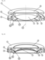
- In the following, further advantages, features, embodiments and aspects of the present invention are described with reference to the Figures, wherein:
- Fig. 1A, 1B
- show cross sectional views of a container and fixed element of a first embodiment of the focus variable lens according to the invention, wherein the membrane comprises different curvatures in
Fig 1A and 1B due to the lens shaper acting on the membrane, which curvatures correspond to different focal lengths of the focus variable lens; - Fig. 2
- shows a perspective view of the first embodiment;
- Fig. 3
- shows an exploded view of the first embodiment;
- Fig. 4A, 4B
- show cross sectional views of a container and fixed element of a second embodiment of the lens according to the invention, wherein the membrane comprises different curvatures in
Fig 4A and 4B due to the lens shaper acting on the membrane, which different curvatures correspond to different focal lengths of the focus variable lens; - Fig. 5
- shows a perspective view of the second embodiment; and
- Fig. 6
- shows an exploded view of the second embodiment;
- Compared to state of the art solutions the improvement and innovation is particularly in the mechanical design which transfers the rotational movement to the linear movement. According to a first and second embodiment, the mechanism is made of at least three main elements: firstly a
rotatable thread ring 10 containing ahelical thread 14, secondly afixed element 1 which typically is in mechanical connection to an outer system or housing and contains a preferably circumferential lens-shaping element (also denoted as lens shaper) 1a which during tuning is applying force on a part of a centrallens container element 5, here on an elastically deformableoptical element 7, preferably on a transparent elasticallydeformable membrane 7, and thirdly the innerlens container element 5 itself, containing theinner counterpart 2 of thehelical thread 14 of thethread ring 10. - The
fixed element 1 can act as rotational guidance for theouter thread ring 10 and at the same time can act as linear guidance for the innerlens container element 5. - Depending on the requirements (such as thermal conductivity, mechanical stiffness, weight, friction coefficient...) that fixed
element 1 can be made out of different materials, such as typically aluminum, steel, brass, plastics or other materials. For assembly reasons, thefixed element 1 is typically made out of two or more components, where one or more can be part of a larger system, such as a camera or other optic devices. Thefixed element 1 can be designed in a way that the interfaces to thethread ring 10 or to the innerlens container element 5 are created as components for rotational 15 orlinear guidance 19 which reduce or adjust mechanical play. To reduce the mechanical friction, both guidances can contain an optimized bearing system. The bearing can be sliding type or ball bearingtype fixed element 1 can contain elastic elements such as helical tension springs 20 (cf.Fig. 6 ) or at least partially can be designed in a semi-flexible manner as flexure bearing 20 (cf.Fig. 3 ), such that there is a defined force which keeps the individual parts of the mechanism always in contact. Suchflexure bearing element 20 is preferably designed in a way that there is a higher stiffness in radial direction and a lower stiffness in axial direction A (the radial direction runs perpendicular to the axial direction A). For withstanding all directions of force - namely radial and axial type, at least one of such ball bearings is designed as an angular ball bearing 13. - The
rotatable thread ring 10 at the interface to thefixed element 1 contains the counterparts of a ball bearing 16, which are also denoted asinner bearings 16 and are formed as ball track inserts 11 (see below). Central part of the respective bearing 13, 15 is aball cage 9 and theballs 17 themselves. Theballs 17 can be made out of all type of materials, such as steel, ceramic, glass or others. The number and size of balls/spheres 17 is typically a function of the mechanical load, the design and the cost requirements. Thespheres 17 are held in place by theball cage 9 which can be made of different materials, such as plastics, brass or others. For optimized functions or performance, thethread ring 10 can be made out of different components or sections having different properties and functionalities. For example: for a higher mechanical load, an optimized metallic ring 11 (e.g. said ball track insert 11) can be placed at the interface to the bearingcage 9. Thethread ring 10 can be combined with a gear of any type to allow a compact transfer of tangential force or momentum. Thethread ring 10 can also contain magnets, in a way that it directly acts as the rotor of an electric motor such as a torque motor, or for angular encoding. It can also be combined with optical encoder wheels. Thethread ring 10 also contains thehelical thread 14 which can be metric, trapezoid, rounded or also other type of thread. The interface to thelens container elements 5 transfers force and therefore typically also can be optimized to reduce mechanical friction. In case of sliding bearing the materials can be chosen accordingly to reduce friction, such as Nycast, NylOil or Delrin, Torlon, Rulon or other plastics, or an appropriate grease could be used. For special applications, the interface can be designed in ball screw system. - The
lens container 5 typically consists of acontainer ring 5a that particularly forms or comprises a circumferentiallateral wall 5c, anelastic membrane 7, a liquidoptical body 18 and a typically rigidtransparent cover element 6. The liquid optical body may be formed by filling the volume of thecontainer 5 which is delimited by themembrane 7, thecontainer ring 5a (particularly saidlateral wall 5c) and thecover element 6 with atransparent liquid 18. Particularly saidmembrane 7 and coverelement 6 are connected to thelateral wall 5c for forming said volume for the liquid 18. Instead of a liquid also a fluid may be used. Here fluid means liquid or gas or a mixture of a liquid or a gas. Further, particularly, in case of an adaptive mirror, the liquid or fluid does not necessarily have to be transparent. - Preferably, as already indicated above, the
container ring 5a is made out of one ormore components nut 2 which may surround thelateral wall 5c and can be fixed to thelateral wall 5c and which comprises anouter thread 14a that engages with thehelical thread 14 is in mechanical contact to the fixedelement 1. The interface is acting asaxial guidance 19 to allow for precise positioning and block thelens container element 5 from rotation with thethread ring 10. Thisaxial guidance 19 preferably consists out of one or more, but typically threevertical posts 19a which are part of the fixedelement 1 and the according through-hole(s) 5b in thelens container ring 5a (e.g. in the first andsecond ring thread ring 10 is particularly optimized in a manner that the system, throughout its complete optical tuning range does not show any kind of mechanical play or hysteresis. This functionality is created by the introduction of one or severalelastic elements 8 which introduce a mechanical preload. Theseelements 8 can either be integrated in thecontainer ring 5a directly by choosing the appropriate elastic material and design, or thecontainer ring 5a can be made out of several components, such as a first (upper) ring ornut 2 and a second (lower) ring ornut 3 with anaxial spring element 8 in between, the optical element (e.g. container 5) being particularly only carried by one of it, e.g. byring 2. Thespring 8 is pushing thecomponents thread ring 10 is maintained always on the same side on thehelical thread 14, independent from the lens tuning position. For this, the elastical element /spring 8 may contain an annular flat base being arranged between the tworings spring 8 comprisesportions 21 that protrude from the base in the axial direction and provide a restoring or elastic force when pushed towards the base. Said portions can rest againstring 2 such that the spring tends to push thering 2 away fromring 3 as described above. - Further, the
spring element 8 can be a spiral spring, leaf spring, volute spring, disc spring, azimuth disc spring, elastomer spring, rubber spring or other elements with comparable function. Furthermore, by not only adding an axial load on thespring 8 but also a rotational preload, in particular when using a spiral spring, the mechanical play between theaxial guidance 19 and the lower 3 andupper ring 2 can be reduced as both the lower andupper rings axial guidance 19. To further reduce the mechanical friction, it is also possible to add a ball bearing to the helical structure, such as a ball screw system. - Above, the two embodiments have been described in conjunction since they show the same or similar essential components. Particularly, as can be seen from the Figures, the second embodiment may differ from the first one in that the inner bearings 16 (cf.
Fig. 5 ) may be integrally formed with thethread ring 10, while in the first embodimentseparate inserts 11 may be used (cf.Fig. 3 ). Further, theelastic bearing 20 of the second embodiment may be formed as helical tension springs 20 (cf.Fig. 6 ) while in the first embodiment, a flexure bearing 20 (e.g. flat springs 20) may be used that may be embedded or integrated into housing part 12 (cf.Fig. 3 ). - Reference numerals used in the drawings and specification:
- 1
- fixed element comprising lens shaping element (also denoted lens shaper)
- 1a
- lens shaping element
- 2
- first ring or nut with outer thread
- 3
- second ring or lock nut with outer thread
- 4
- Top cover glass
- 5
- Container (also denoted container element)
- 5a
- Container ring
- 5b
- through holes
- 5c
- lateral wall
- 6
- Bottom cover glass
- 7
- Membrane
- 8
- Spring structure
- 9
- Ball cage with balls
- 10
- Thread ring with outer helical thread and inner flat thread
- 11
- Ball track insert
- 12
- Housing with ball track and flexure bearing
- 13
- Angular ball bearing
- 14
- Helical thread
- 14a
- outer thread of
container ring 5a meshing withhelical thread 14 - 15
- Ball bearing
- 16
- Inner bearing
- 17
- Balls
- 18
- Liquid
- 19
- Axial guiding interface
- 20
- Flexural bearing or helical tension spring
- 21
- Spring
Claims (8)
- A variable focus lens comprising an elastically deformable optical element (7) and a circumferential mechanism (10, 1, 5, 2, 3, 8, 21) to transfer a rotational movement to an axial movement, wherein said mechanism comprises a ball bearing system (9, 11, 12, 13, 15, 16, 17) and an outer thread ring (10) with a helical thread (14), which thread ring (10) is supported on a fixed element (1) via a ball bearing (13) comprised by the ball bearing system so that the thread ring (10) is rotatable with respect to the fixed element (1) about the axial direction, wherein the lens comprises at least one ring-shaped elastic spring element (8, 21) applying a preloading force in a primarily axial direction (A), avoiding axial play within a helical thread (14), minimizing optical hysteresis in a focal length thereof, wherein the lens comprises a container element (5), which comprises a container ring (5a), wherein the container ring (5a) comprises an outer thread (14a) that meshes with the helical thread (14) so that the container element (5) is moved axially in the axial direction (A) when the thread ring (10) is rotated about the axial direction (A), and wherein
either the elastic spring element (8) is integrated in the container ring (5a) or the container ring is made of several components, wherein the container ring (5a) comprises a first ring (2) and a second ring (3) which both form said outer thread (14a) of the container ring (5a), wherein the spring element (8) is arranged between the first ring (2) and the second ring (3) and is configured to push said rings (2, 3) apart, so as to reduce an axial play of the helical thread (14). - The lens of claim 1, wherein the elastic element (8, 21) is configured to preload the ball bearing system.
- The lens of claim 1 or 2, wherein the spring element (8, 21) is also configured to apply a preload in a rotational direction to reduce rotational play.
- The lens of one of the preceding claims, wherein the lens comprises a transparent and elastically deformable membrane (7), and a transparent cover element (6) facing said membrane (7) in the axial direction (A), wherein the membrane (7), the container ring (5a) and the cover element (6) delimit a volume of the container element (5) that is filled with a fluid, particularly a transparent liquid (18).
- The lens of claim 4, wherein the container element (5) is guided by a plurality of posts (19a) protruding from the fixed element (1) in the axial direction (A) and extending through through holes (5b) in the container ring (5a).
- The lens of claim 4 or 5, wherein a lens shaping element (1a) that protrudes from the fixed element (1) is configured to press against the membrane (7) depending on the axial position of the container element (5) so that a curvature of the membrane (7) and therewith the focal length of the lens is adjustable by said axial movement of the container element (5).
- The lens according to one of the preceding claims, wherein the spring element (8) is configured to push said rings (2, 3) apart in a way that the axial contact to the thread ring (10) is maintained always on the same side on the helical thread (14).
- The lens of one of the preceding claims, wherein the thread ring (10) is also supported on a housing part (12) that faces the fixed element (1) in the axial direction (A) via a further ball bearing (15) comprised by said ball bearing system, wherein said housing part (12) holds a further transparent cover element (4) facing said cover element (6) of the container element (5) in the axial direction (A), and wherein said housing part (12) is connected to the vertical posts (19a) via an elastic bearing (20).
Applications Claiming Priority (2)
| Application Number | Priority Date | Filing Date | Title |
|---|---|---|---|
| US201562137280P | 2015-03-24 | 2015-03-24 | |
| PCT/EP2016/056680 WO2016151123A1 (en) | 2015-03-24 | 2016-03-24 | Variable focus lens |
Publications (2)
| Publication Number | Publication Date |
|---|---|
| EP3274744A1 EP3274744A1 (en) | 2018-01-31 |
| EP3274744B1 true EP3274744B1 (en) | 2024-07-10 |
Family
ID=55802328
Family Applications (1)
| Application Number | Title | Priority Date | Filing Date |
|---|---|---|---|
| EP16717568.6A Active EP3274744B1 (en) | 2015-03-24 | 2016-03-24 | Variable focus lens |
Country Status (3)
| Country | Link |
|---|---|
| US (1) | US10371870B2 (en) |
| EP (1) | EP3274744B1 (en) |
| WO (1) | WO2016151123A1 (en) |
Families Citing this family (3)
| Publication number | Priority date | Publication date | Assignee | Title |
|---|---|---|---|---|
| WO2019110617A1 (en) * | 2017-12-04 | 2019-06-13 | Optotune Consumer Ag | Optical zoom device with focus tunable lens cores |
| CN110568503B (en) * | 2019-09-14 | 2021-01-05 | 吉林大学 | Metal object shielding and isolating device for nuclear magnetic resonance |
| EP4275589A1 (en) | 2022-05-11 | 2023-11-15 | Roche Diabetes Care GmbH | Insertion system |
Citations (2)
| Publication number | Priority date | Publication date | Assignee | Title |
|---|---|---|---|---|
| CH501232A (en) * | 1969-04-26 | 1970-12-31 | Leitz Ernst Gmbh | Holder for microscope objectives |
| US20110102606A1 (en) * | 2009-11-05 | 2011-05-05 | Panasonic Corporation | Image capturing device and network camera system |
Family Cites Families (13)
| Publication number | Priority date | Publication date | Assignee | Title |
|---|---|---|---|---|
| US3432218A (en) * | 1966-09-30 | 1969-03-11 | Goodyear Aerospace Corp | High speed mechanical variable amplitude nutating mechanism |
| US3830021A (en) * | 1972-10-10 | 1974-08-20 | R Blum | Spherical bearing workpiece holder in an optical lens generating machine |
| US3913061A (en) * | 1973-04-25 | 1975-10-14 | Stanford Research Inst | Focusing and deflecting system for acoustic imaging |
| JP3030050B2 (en) * | 1989-05-30 | 2000-04-10 | オリンパス光学工業株式会社 | Ultrasonic motor |
| AU2001251742A1 (en) * | 2000-04-03 | 2001-10-15 | Pocketscope. Com Llc | Lenses and uses, including microscopes |
| US7646544B2 (en) | 2005-05-14 | 2010-01-12 | Batchko Robert G | Fluidic optical devices |
| US8096674B2 (en) * | 2003-12-09 | 2012-01-17 | Surefire, Llc | Lighting device with selectable output level switching |
| JP4963415B2 (en) * | 2007-01-15 | 2012-06-27 | ペンタックスリコーイメージング株式会社 | camera |
| EP2034338A1 (en) | 2007-08-11 | 2009-03-11 | ETH Zurich | Liquid Lens System |
| US20100023216A1 (en) * | 2008-07-24 | 2010-01-28 | Gm Global Technology Operations, Inc | Adaptive vehicle control system with driving style recognition based on vehicle left/right turns |
| US8699141B2 (en) | 2009-03-13 | 2014-04-15 | Knowles Electronics, Llc | Lens assembly apparatus and method |
| CA2671171C (en) * | 2009-07-06 | 2017-12-12 | Northbasin Energy Services Inc. | Drill bit with a flow interrupter |
| US20120069165A1 (en) * | 2010-09-16 | 2012-03-22 | Seung-Lyul Choi | Location-based av flashlight and method of displaying map related video thereof |
-
2016
- 2016-03-24 US US15/561,054 patent/US10371870B2/en active Active
- 2016-03-24 WO PCT/EP2016/056680 patent/WO2016151123A1/en not_active Ceased
- 2016-03-24 EP EP16717568.6A patent/EP3274744B1/en active Active
Patent Citations (2)
| Publication number | Priority date | Publication date | Assignee | Title |
|---|---|---|---|---|
| CH501232A (en) * | 1969-04-26 | 1970-12-31 | Leitz Ernst Gmbh | Holder for microscope objectives |
| US20110102606A1 (en) * | 2009-11-05 | 2011-05-05 | Panasonic Corporation | Image capturing device and network camera system |
Also Published As
| Publication number | Publication date |
|---|---|
| WO2016151123A1 (en) | 2016-09-29 |
| US10371870B2 (en) | 2019-08-06 |
| US20180074233A1 (en) | 2018-03-15 |
| EP3274744A1 (en) | 2018-01-31 |
Similar Documents
| Publication | Publication Date | Title |
|---|---|---|
| WO2016173620A1 (en) | Contact and intraocular lenses comprising an adjustable focus length | |
| US10371870B2 (en) | Variable focus lens | |
| Savidis et al. | Nonmechanical zoom system through<? A3B2 show [pmg: line-break justify=" yes"/]?> pressure-controlled tunable<? A3B2 show [pmg: line-break justify=" yes"/]?> fluidic lenses | |
| US11561361B2 (en) | Optical apparatus | |
| JP6625090B2 (en) | Lens device and imaging device having the same | |
| CN111258052A (en) | Endoscope with a detachable handle | |
| US8437078B2 (en) | Binoculars | |
| US20160036293A1 (en) | Actuator device and method of converting rotational input to axial output with rotary flexure mechanism | |
| JP2016511439A5 (en) | ||
| JP2015158629A (en) | Lens barrel, lens apparatus and imaging apparatus having the same | |
| JP4974537B2 (en) | Focus adjustment device and optical apparatus | |
| JP2005352132A (en) | Camera unit | |
| WO2021064149A1 (en) | Cylindrical actuator subassembly with flexure-based linear guidance mechanism | |
| JP6535751B2 (en) | binoculars | |
| US5949575A (en) | Binocular telescope | |
| JP7336356B2 (en) | Lens device and imaging device | |
| US8885263B2 (en) | Optical zoom lens system | |
| JP7292976B2 (en) | Lens device and imaging device | |
| US8167443B2 (en) | Optical observation apparatus | |
| EP4332643B1 (en) | Arrangement for a tunable lens | |
| US20160187614A1 (en) | Autofocus system | |
| JP6990304B2 (en) | Optical equipment and how to focus the optical equipment | |
| CN111258051A (en) | Endoscope with a detachable handle | |
| JP6701370B2 (en) | binoculars | |
| JP2010214053A (en) | Actuator built-in distal end of endoscope |
Legal Events
| Date | Code | Title | Description |
|---|---|---|---|
| STAA | Information on the status of an ep patent application or granted ep patent |
Free format text: STATUS: THE INTERNATIONAL PUBLICATION HAS BEEN MADE |
|
| PUAI | Public reference made under article 153(3) epc to a published international application that has entered the european phase |
Free format text: ORIGINAL CODE: 0009012 |
|
| STAA | Information on the status of an ep patent application or granted ep patent |
Free format text: STATUS: REQUEST FOR EXAMINATION WAS MADE |
|
| 17P | Request for examination filed |
Effective date: 20171024 |
|
| AK | Designated contracting states |
Kind code of ref document: A1 Designated state(s): AL AT BE BG CH CY CZ DE DK EE ES FI FR GB GR HR HU IE IS IT LI LT LU LV MC MK MT NL NO PL PT RO RS SE SI SK SM TR |
|
| AX | Request for extension of the european patent |
Extension state: BA ME |
|
| DAV | Request for validation of the european patent (deleted) | ||
| DAX | Request for extension of the european patent (deleted) | ||
| RIN1 | Information on inventor provided before grant (corrected) |
Inventor name: NIEDERER, DAVID Inventor name: ASCHWANDEN, MANUEL Inventor name: WAIBEL, PHILIPP |
|
| STAA | Information on the status of an ep patent application or granted ep patent |
Free format text: STATUS: EXAMINATION IS IN PROGRESS |
|
| 17Q | First examination report despatched |
Effective date: 20210610 |
|
| RAP1 | Party data changed (applicant data changed or rights of an application transferred) |
Owner name: OPTOTUNE SWITZERLAND AG |
|
| GRAP | Despatch of communication of intention to grant a patent |
Free format text: ORIGINAL CODE: EPIDOSNIGR1 |
|
| STAA | Information on the status of an ep patent application or granted ep patent |
Free format text: STATUS: GRANT OF PATENT IS INTENDED |
|
| INTG | Intention to grant announced |
Effective date: 20230905 |
|
| GRAJ | Information related to disapproval of communication of intention to grant by the applicant or resumption of examination proceedings by the epo deleted |
Free format text: ORIGINAL CODE: EPIDOSDIGR1 |
|
| STAA | Information on the status of an ep patent application or granted ep patent |
Free format text: STATUS: EXAMINATION IS IN PROGRESS |
|
| GRAP | Despatch of communication of intention to grant a patent |
Free format text: ORIGINAL CODE: EPIDOSNIGR1 |
|
| STAA | Information on the status of an ep patent application or granted ep patent |
Free format text: STATUS: GRANT OF PATENT IS INTENDED |
|
| INTC | Intention to grant announced (deleted) | ||
| INTG | Intention to grant announced |
Effective date: 20240202 |
|
| GRAS | Grant fee paid |
Free format text: ORIGINAL CODE: EPIDOSNIGR3 |
|
| GRAA | (expected) grant |
Free format text: ORIGINAL CODE: 0009210 |
|
| STAA | Information on the status of an ep patent application or granted ep patent |
Free format text: STATUS: THE PATENT HAS BEEN GRANTED |
|
| AK | Designated contracting states |
Kind code of ref document: B1 Designated state(s): AL AT BE BG CH CY CZ DE DK EE ES FI FR GB GR HR HU IE IS IT LI LT LU LV MC MK MT NL NO PL PT RO RS SE SI SK SM TR |
|
| REG | Reference to a national code |
Ref country code: CH Ref legal event code: EP |
|
| REG | Reference to a national code |
Ref country code: DE Ref legal event code: R096 Ref document number: 602016088328 Country of ref document: DE |
|
| REG | Reference to a national code |
Ref country code: LT Ref legal event code: MG9D |
|
| REG | Reference to a national code |
Ref country code: NL Ref legal event code: MP Effective date: 20240710 |
|
| PG25 | Lapsed in a contracting state [announced via postgrant information from national office to epo] |
Ref country code: PT Free format text: LAPSE BECAUSE OF FAILURE TO SUBMIT A TRANSLATION OF THE DESCRIPTION OR TO PAY THE FEE WITHIN THE PRESCRIBED TIME-LIMIT Effective date: 20241111 |
|
| REG | Reference to a national code |
Ref country code: AT Ref legal event code: MK05 Ref document number: 1702534 Country of ref document: AT Kind code of ref document: T Effective date: 20240710 |
|
| PG25 | Lapsed in a contracting state [announced via postgrant information from national office to epo] |
Ref country code: NL Free format text: LAPSE BECAUSE OF FAILURE TO SUBMIT A TRANSLATION OF THE DESCRIPTION OR TO PAY THE FEE WITHIN THE PRESCRIBED TIME-LIMIT Effective date: 20240710 |
|
| PG25 | Lapsed in a contracting state [announced via postgrant information from national office to epo] |
Ref country code: PT Free format text: LAPSE BECAUSE OF FAILURE TO SUBMIT A TRANSLATION OF THE DESCRIPTION OR TO PAY THE FEE WITHIN THE PRESCRIBED TIME-LIMIT Effective date: 20241111 Ref country code: NL Free format text: LAPSE BECAUSE OF FAILURE TO SUBMIT A TRANSLATION OF THE DESCRIPTION OR TO PAY THE FEE WITHIN THE PRESCRIBED TIME-LIMIT Effective date: 20240710 |
|
| PG25 | Lapsed in a contracting state [announced via postgrant information from national office to epo] |
Ref country code: NO Free format text: LAPSE BECAUSE OF FAILURE TO SUBMIT A TRANSLATION OF THE DESCRIPTION OR TO PAY THE FEE WITHIN THE PRESCRIBED TIME-LIMIT Effective date: 20241010 |
|
| PG25 | Lapsed in a contracting state [announced via postgrant information from national office to epo] |
Ref country code: PL Free format text: LAPSE BECAUSE OF FAILURE TO SUBMIT A TRANSLATION OF THE DESCRIPTION OR TO PAY THE FEE WITHIN THE PRESCRIBED TIME-LIMIT Effective date: 20240710 Ref country code: GR Free format text: LAPSE BECAUSE OF FAILURE TO SUBMIT A TRANSLATION OF THE DESCRIPTION OR TO PAY THE FEE WITHIN THE PRESCRIBED TIME-LIMIT Effective date: 20241011 Ref country code: FI Free format text: LAPSE BECAUSE OF FAILURE TO SUBMIT A TRANSLATION OF THE DESCRIPTION OR TO PAY THE FEE WITHIN THE PRESCRIBED TIME-LIMIT Effective date: 20240710 |
|
| PG25 | Lapsed in a contracting state [announced via postgrant information from national office to epo] |
Ref country code: BG Free format text: LAPSE BECAUSE OF FAILURE TO SUBMIT A TRANSLATION OF THE DESCRIPTION OR TO PAY THE FEE WITHIN THE PRESCRIBED TIME-LIMIT Effective date: 20240710 |
|
| PG25 | Lapsed in a contracting state [announced via postgrant information from national office to epo] |
Ref country code: LV Free format text: LAPSE BECAUSE OF FAILURE TO SUBMIT A TRANSLATION OF THE DESCRIPTION OR TO PAY THE FEE WITHIN THE PRESCRIBED TIME-LIMIT Effective date: 20240710 |
|
| PG25 | Lapsed in a contracting state [announced via postgrant information from national office to epo] |
Ref country code: IS Free format text: LAPSE BECAUSE OF FAILURE TO SUBMIT A TRANSLATION OF THE DESCRIPTION OR TO PAY THE FEE WITHIN THE PRESCRIBED TIME-LIMIT Effective date: 20241110 Ref country code: AT Free format text: LAPSE BECAUSE OF FAILURE TO SUBMIT A TRANSLATION OF THE DESCRIPTION OR TO PAY THE FEE WITHIN THE PRESCRIBED TIME-LIMIT Effective date: 20240710 |
|
| PG25 | Lapsed in a contracting state [announced via postgrant information from national office to epo] |
Ref country code: HR Free format text: LAPSE BECAUSE OF FAILURE TO SUBMIT A TRANSLATION OF THE DESCRIPTION OR TO PAY THE FEE WITHIN THE PRESCRIBED TIME-LIMIT Effective date: 20240710 |
|
| PG25 | Lapsed in a contracting state [announced via postgrant information from national office to epo] |
Ref country code: RS Free format text: LAPSE BECAUSE OF FAILURE TO SUBMIT A TRANSLATION OF THE DESCRIPTION OR TO PAY THE FEE WITHIN THE PRESCRIBED TIME-LIMIT Effective date: 20241010 Ref country code: ES Free format text: LAPSE BECAUSE OF FAILURE TO SUBMIT A TRANSLATION OF THE DESCRIPTION OR TO PAY THE FEE WITHIN THE PRESCRIBED TIME-LIMIT Effective date: 20240710 |
|
| PG25 | Lapsed in a contracting state [announced via postgrant information from national office to epo] |
Ref country code: RS Free format text: LAPSE BECAUSE OF FAILURE TO SUBMIT A TRANSLATION OF THE DESCRIPTION OR TO PAY THE FEE WITHIN THE PRESCRIBED TIME-LIMIT Effective date: 20241010 Ref country code: PL Free format text: LAPSE BECAUSE OF FAILURE TO SUBMIT A TRANSLATION OF THE DESCRIPTION OR TO PAY THE FEE WITHIN THE PRESCRIBED TIME-LIMIT Effective date: 20240710 Ref country code: NO Free format text: LAPSE BECAUSE OF FAILURE TO SUBMIT A TRANSLATION OF THE DESCRIPTION OR TO PAY THE FEE WITHIN THE PRESCRIBED TIME-LIMIT Effective date: 20241010 Ref country code: LV Free format text: LAPSE BECAUSE OF FAILURE TO SUBMIT A TRANSLATION OF THE DESCRIPTION OR TO PAY THE FEE WITHIN THE PRESCRIBED TIME-LIMIT Effective date: 20240710 Ref country code: IS Free format text: LAPSE BECAUSE OF FAILURE TO SUBMIT A TRANSLATION OF THE DESCRIPTION OR TO PAY THE FEE WITHIN THE PRESCRIBED TIME-LIMIT Effective date: 20241110 Ref country code: HR Free format text: LAPSE BECAUSE OF FAILURE TO SUBMIT A TRANSLATION OF THE DESCRIPTION OR TO PAY THE FEE WITHIN THE PRESCRIBED TIME-LIMIT Effective date: 20240710 Ref country code: GR Free format text: LAPSE BECAUSE OF FAILURE TO SUBMIT A TRANSLATION OF THE DESCRIPTION OR TO PAY THE FEE WITHIN THE PRESCRIBED TIME-LIMIT Effective date: 20241011 Ref country code: FI Free format text: LAPSE BECAUSE OF FAILURE TO SUBMIT A TRANSLATION OF THE DESCRIPTION OR TO PAY THE FEE WITHIN THE PRESCRIBED TIME-LIMIT Effective date: 20240710 Ref country code: ES Free format text: LAPSE BECAUSE OF FAILURE TO SUBMIT A TRANSLATION OF THE DESCRIPTION OR TO PAY THE FEE WITHIN THE PRESCRIBED TIME-LIMIT Effective date: 20240710 Ref country code: BG Free format text: LAPSE BECAUSE OF FAILURE TO SUBMIT A TRANSLATION OF THE DESCRIPTION OR TO PAY THE FEE WITHIN THE PRESCRIBED TIME-LIMIT Effective date: 20240710 Ref country code: AT Free format text: LAPSE BECAUSE OF FAILURE TO SUBMIT A TRANSLATION OF THE DESCRIPTION OR TO PAY THE FEE WITHIN THE PRESCRIBED TIME-LIMIT Effective date: 20240710 |
|
| REG | Reference to a national code |
Ref country code: DE Ref legal event code: R097 Ref document number: 602016088328 Country of ref document: DE |
|
| PG25 | Lapsed in a contracting state [announced via postgrant information from national office to epo] |
Ref country code: RO Free format text: LAPSE BECAUSE OF FAILURE TO SUBMIT A TRANSLATION OF THE DESCRIPTION OR TO PAY THE FEE WITHIN THE PRESCRIBED TIME-LIMIT Effective date: 20240710 Ref country code: SM Free format text: LAPSE BECAUSE OF FAILURE TO SUBMIT A TRANSLATION OF THE DESCRIPTION OR TO PAY THE FEE WITHIN THE PRESCRIBED TIME-LIMIT Effective date: 20240710 Ref country code: DK Free format text: LAPSE BECAUSE OF FAILURE TO SUBMIT A TRANSLATION OF THE DESCRIPTION OR TO PAY THE FEE WITHIN THE PRESCRIBED TIME-LIMIT Effective date: 20240710 |
|
| PG25 | Lapsed in a contracting state [announced via postgrant information from national office to epo] |
Ref country code: EE Free format text: LAPSE BECAUSE OF FAILURE TO SUBMIT A TRANSLATION OF THE DESCRIPTION OR TO PAY THE FEE WITHIN THE PRESCRIBED TIME-LIMIT Effective date: 20240710 |
|
| PG25 | Lapsed in a contracting state [announced via postgrant information from national office to epo] |
Ref country code: CZ Free format text: LAPSE BECAUSE OF FAILURE TO SUBMIT A TRANSLATION OF THE DESCRIPTION OR TO PAY THE FEE WITHIN THE PRESCRIBED TIME-LIMIT Effective date: 20240710 |
|
| PG25 | Lapsed in a contracting state [announced via postgrant information from national office to epo] |
Ref country code: SK Free format text: LAPSE BECAUSE OF FAILURE TO SUBMIT A TRANSLATION OF THE DESCRIPTION OR TO PAY THE FEE WITHIN THE PRESCRIBED TIME-LIMIT Effective date: 20240710 Ref country code: IT Free format text: LAPSE BECAUSE OF FAILURE TO SUBMIT A TRANSLATION OF THE DESCRIPTION OR TO PAY THE FEE WITHIN THE PRESCRIBED TIME-LIMIT Effective date: 20240710 |
|
| PLBE | No opposition filed within time limit |
Free format text: ORIGINAL CODE: 0009261 |
|
| STAA | Information on the status of an ep patent application or granted ep patent |
Free format text: STATUS: NO OPPOSITION FILED WITHIN TIME LIMIT |
|
| 26N | No opposition filed |
Effective date: 20250411 |
|
| PGFP | Annual fee paid to national office [announced via postgrant information from national office to epo] |
Ref country code: CH Payment date: 20250616 Year of fee payment: 10 |
|
| PG25 | Lapsed in a contracting state [announced via postgrant information from national office to epo] |
Ref country code: SE Free format text: LAPSE BECAUSE OF FAILURE TO SUBMIT A TRANSLATION OF THE DESCRIPTION OR TO PAY THE FEE WITHIN THE PRESCRIBED TIME-LIMIT Effective date: 20240710 |
|
| PG25 | Lapsed in a contracting state [announced via postgrant information from national office to epo] |
Ref country code: MC Free format text: LAPSE BECAUSE OF FAILURE TO SUBMIT A TRANSLATION OF THE DESCRIPTION OR TO PAY THE FEE WITHIN THE PRESCRIBED TIME-LIMIT Effective date: 20240710 |
|
| PG25 | Lapsed in a contracting state [announced via postgrant information from national office to epo] |
Ref country code: LU Free format text: LAPSE BECAUSE OF NON-PAYMENT OF DUE FEES Effective date: 20250324 |
|
| REG | Reference to a national code |
Ref country code: BE Ref legal event code: MM Effective date: 20250331 |
|
| PG25 | Lapsed in a contracting state [announced via postgrant information from national office to epo] |
Ref country code: BE Free format text: LAPSE BECAUSE OF NON-PAYMENT OF DUE FEES Effective date: 20250331 |
|
| PG25 | Lapsed in a contracting state [announced via postgrant information from national office to epo] |
Ref country code: IE Free format text: LAPSE BECAUSE OF NON-PAYMENT OF DUE FEES Effective date: 20250324 |
|
| PGFP | Annual fee paid to national office [announced via postgrant information from national office to epo] |
Ref country code: GB Payment date: 20260324 Year of fee payment: 11 |
|
| PGFP | Annual fee paid to national office [announced via postgrant information from national office to epo] |
Ref country code: DE Payment date: 20260319 Year of fee payment: 11 |
|
| PGFP | Annual fee paid to national office [announced via postgrant information from national office to epo] |
Ref country code: FR Payment date: 20260320 Year of fee payment: 11 |