EP3273758A1 - Network distribution adapter for a motor control center - Google Patents
Network distribution adapter for a motor control center Download PDFInfo
- Publication number
- EP3273758A1 EP3273758A1 EP17178257.6A EP17178257A EP3273758A1 EP 3273758 A1 EP3273758 A1 EP 3273758A1 EP 17178257 A EP17178257 A EP 17178257A EP 3273758 A1 EP3273758 A1 EP 3273758A1
- Authority
- EP
- European Patent Office
- Prior art keywords
- network
- pcb
- jack
- housing
- plane
- Prior art date
- Legal status (The legal status is an assumption and is not a legal conclusion. Google has not performed a legal analysis and makes no representation as to the accuracy of the status listed.)
- Granted
Links
Images




Classifications
-
- H—ELECTRICITY
- H01—ELECTRIC ELEMENTS
- H01R—ELECTRICALLY-CONDUCTIVE CONNECTIONS; STRUCTURAL ASSOCIATIONS OF A PLURALITY OF MUTUALLY-INSULATED ELECTRICAL CONNECTING ELEMENTS; COUPLING DEVICES; CURRENT COLLECTORS
- H01R31/00—Coupling parts supported only by co-operation with counterpart
- H01R31/005—Intermediate parts for distributing signals
-
- H—ELECTRICITY
- H04—ELECTRIC COMMUNICATION TECHNIQUE
- H04Q—SELECTING
- H04Q1/00—Details of selecting apparatus or arrangements
- H04Q1/02—Constructional details
- H04Q1/06—Cable ducts or mountings specially adapted for exchange installations
-
- H—ELECTRICITY
- H04—ELECTRIC COMMUNICATION TECHNIQUE
- H04Q—SELECTING
- H04Q1/00—Details of selecting apparatus or arrangements
- H04Q1/02—Constructional details
- H04Q1/13—Patch panels for monitoring, interconnecting or testing circuits, e.g. patch bay, patch field or jack field; Patching modules
-
- H—ELECTRICITY
- H05—ELECTRIC TECHNIQUES NOT OTHERWISE PROVIDED FOR
- H05K—PRINTED CIRCUITS; CASINGS OR CONSTRUCTIONAL DETAILS OF ELECTRIC APPARATUS; MANUFACTURE OF ASSEMBLAGES OF ELECTRICAL COMPONENTS
- H05K7/00—Constructional details common to different types of electric apparatus
- H05K7/14—Mounting supporting structure in casing or on frame or rack
- H05K7/1422—Printed circuit boards receptacles, e.g. stacked structures, electronic circuit modules or box like frames
- H05K7/1427—Housings
- H05K7/1432—Housings specially adapted for power drive units or power converters
-
- H—ELECTRICITY
- H05—ELECTRIC TECHNIQUES NOT OTHERWISE PROVIDED FOR
- H05K—PRINTED CIRCUITS; CASINGS OR CONSTRUCTIONAL DETAILS OF ELECTRIC APPARATUS; MANUFACTURE OF ASSEMBLAGES OF ELECTRICAL COMPONENTS
- H05K7/00—Constructional details common to different types of electric apparatus
- H05K7/14—Mounting supporting structure in casing or on frame or rack
- H05K7/1422—Printed circuit boards receptacles, e.g. stacked structures, electronic circuit modules or box like frames
- H05K7/1427—Housings
- H05K7/1432—Housings specially adapted for power drive units or power converters
- H05K7/14325—Housings specially adapted for power drive units or power converters for cabinets or racks
-
- H—ELECTRICITY
- H05—ELECTRIC TECHNIQUES NOT OTHERWISE PROVIDED FOR
- H05K—PRINTED CIRCUITS; CASINGS OR CONSTRUCTIONAL DETAILS OF ELECTRIC APPARATUS; MANUFACTURE OF ASSEMBLAGES OF ELECTRICAL COMPONENTS
- H05K7/00—Constructional details common to different types of electric apparatus
- H05K7/14—Mounting supporting structure in casing or on frame or rack
- H05K7/1422—Printed circuit boards receptacles, e.g. stacked structures, electronic circuit modules or box like frames
- H05K7/1427—Housings
- H05K7/1432—Housings specially adapted for power drive units or power converters
- H05K7/14327—Housings specially adapted for power drive units or power converters having supplementary functional units, e.g. data transfer modules or displays or user interfaces
Definitions
- the present invention relates generally to electrical distribution systems, such as for the distribution of power signals to controlled equipment, and more particularly, to a network distribution adapter for electrical units which may be intelligently controlled in such systems.
- MCC Motor Control Centers
- switchgear semiconductor power electronic circuits
- programmable logic controllers programmable logic controllers
- motor controllers and so forth
- the MCC includes associated bus bars, interconnections and supporting structures for distribution of electrical power to the various compartments.
- Some units in MCC's may be "intelligently" controlled by a network connection to another device, such as a Programmable Logic Controller (PLC).
- PLC Programmable Logic Controller
- Vertical and horizontal wire-ways ordinarily used for running line and load wiring to service components of the MCC, may also be used for running such network cables.
- running network cables in such wire-ways may be a challenge.
- a network distribution adapter may be configured to vertically connect a network cable on one side of an isolation wall (within a vertical wire-way) while connecting another network cable at an angle on an opposing side of the isolation wall (interior to the MCC). This may advantageously allow fitting the adapter in the limited space provided by the vertical wire-way while also providing more reliable protection for the network connections.
- the network distribution adapter may include a printed circuit board (PCB) which couples a first connector disposed in a first plane parallel to the PCB with a second connector disposed in a second plane at an angle to the first plane.
- the PCB may be mounted in a housing which, in turn, may be mounted in relation to an opening in the isolation wall.
- an Ethernet (or EtherNet/IP) adapter may be mounted in a vertical wire-way of each plug-in section within an MCC and each may be connected to a network access device with Ethernet cables being routed behind the vertical wire-way. This may allow for an Ethernet infrastructure to be pre-installed and organized, out of the way of end user cables which may also be routed through the vertical wire-ways.
- Each adapter may allow, for example, two Ethernet connections.
- Each section may accommodate, for example, up to four adapters which may provide up to eight connection points within each section.
- a device within the unit may be connected to the Ethernet adapters with short patch cables that can be easily managed and angled downward so that an end user is protected from breaking the adapter or Ethernet connection of a unit during commissioning activities. Accordingly, an adapter may provide routing for cables up or down behind the power wire-way within the same footprint, thereby providing protection for the cable connections to Ethernet enabled units, which may be replaced in the field.
- Ethernet adapters could consist of a plastic housing and lid, for example, molded from a hardened resin, such as Valox 420SE0.
- the housing could include supports for a printed circuit board (PCB) and an emboss side which may snap fit together from two halves.
- PCB printed circuit board
- the housing could be approximately 2-1/4 inches wide by 2-1/4 inches long by 1-3/8" deep, and may be sloped at the top to include a recessed area to affix a 1.25 inches by 0.25 inch adapter port label.
- the adapter may be mounted in the front of the power wire-way to allow it to be field replaceable.
- the PCB may be designed with two straight RJ-45 connectors facing down on one side of the board and two angled RJ-45 connectors (45°) facing either up or down on the other side of the board.
- the top and bottom adapters may use the same plastic housing but different PCBs based on which angled connector is used.
- one aspect of the invention may provide a network distribution adapter including: a housing; a printed circuit board (PCB) mounted in the housing, the PCB having top and bottom sides; a first network connector mounted to the top side of the PCB, the first network connector providing a top jack accessible through the housing, the top jack being disposed in a first plane parallel to the PCB; and a second network connector mounted to the bottom side of the PCB, the second network connector providing a bottom jack accessible through the housing, the bottom jack being disposed in a second plane at an angle to the first plane.
- PCB printed circuit board
- MCC Motor Control Center
- An enclosure having a device mounting volume for supporting electrical units; a vertical wire-way disposed adjacently to the device mounting volume; a wall separating the vertical wire-way from an interior portion of the section; and a network distribution adapter including: a housing; a PCB mounted in the housing, the PCB having top and bottom sides; a first network connector mounted to the top side of the PCB, the first network connector providing a top jack accessible through the housing, the top jack being disposed in a first plane parallel to the PCB; and a second network connector mounted to the bottom side of the PCB, the second network connector providing a bottom jack accessible through the housing, the bottom jack being disposed in a second plane at an angle to the first plane.
- the network distribution adapter may be mounted to an opening in the wall so that the first network connector is accessible in the vertical wire-way and the second network connector is accessible in the interior portion of the section.
- an exemplary electrical system 10 is provided in which electrical units 12 (such as units 12a, 12b and 12c as illustrated) of various types may be housed.
- the electrical system 10 may be, for example, a Motor Control Center ("MCC") or other industrial, commercial, marine, or other electrical system.
- MCC Motor Control Center
- One example of an electrical system 10 could be the Centerline 2100 Motor Control Center available from Rockwell Automation, Inc.
- the electrical system 10 may provide one or more sections 14 (such as sections 14a, 14b and 14c as illustrated), each forming a shell around a device mounting volume for supporting the units 12.
- the shell may be made of any suitable material, such as heavy gage sheet metal, reinforced plastics, and so forth.
- the units 12 may typically be "plug-in" units which may be inserted and removed from a section 14, or "frame-mounted” units which may be built with a frame-mounted construction permanently mounted to a section 14 which cannot be easily inserted or removed.
- the electrical system 10 may typically receive three-phase power from an external power supply, such as a power supply grid, and/or data signals, via appropriate conduits (not shown), and distribute the received power and/or data signals to one or more of the sections 14 in various manners.
- the sections 14 may be electrically isolated from one another, or alternatively, may be electrically joined with other sections 14, such as via common horizontal power buses (not shown).
- the units 12 may each include a door for covering an assembly of components that are supported within each unit 12 via known methods, such as screwed or snap-in engagement, thereby providing mechanical and electrical connection to the electrical system 10.
- Exemplary components of the units 12 may include relays, motor starters, and Programmable Logic Controllers ("PLC's"), among others.
- Doors for the units 12 may include, for example, levers for operating disconnect switches, locks for preventing the doors from opening, and/or lights for indicating a safe condition for opening the doors.
- a latch rail (not shown) may be provided in each section 14 to interface with latches on the individual doors of the units 12.
- the sections 14 may also include built-in wire-ways in which line and load wiring, cabling, and other connections may be made inside the electrical system 10.
- Vertical wire-ways 16 (such as vertical wire-way 16c, for the section 14c, as illustrated) may be disposed vertically in each section 14, adjacent to the device mounting volume for supporting the units 12.
- horizontal wire-ways 18 may be disposed horizontally in each section 14, such as upper horizontal wire-way 18a disposed horizontally above and adjacent to the upper most device mounting volume, and lower horizontal wire-ways 18b disposed horizontally below and adjacent to the lower most device mounting volume.
- the section 14 may be defined by an enclosure 20 forming a shell around the device mounting volumes 22 (such as device mounting volumes 22a through 22f as illustrated) for supporting the units 12.
- An isolation wall 24 may separate the vertical wire-way 16 from an interior portion of the section 14 and the electrical system 10 while still providing openings for network distribution adapters as will be further described.
- a vertical wire-way wall 25 may separate the vertical wire-way 16 from the device mounting volumes 22 while still providing access areas 23 for network cables and/or other wiring to run between the vertical wire-way 16 and the device mounting volumes 22.
- an "intelligent" unit 12a which could be, for example, an EtherNet/IP controlled motor in the device mounting volume 22a, may be installed by an end user for control via a network connection with another device.
- a network connection could be made, for example, to another device in the electrical system 10, such as a network switch 27 provided in the upper horizontal wire-way 18a.
- a network switch 27 could be a Stratix 5700 industrial managed Ethernet switch available from Rockwell Automation, Inc.
- such a network connection could be made to a PLC implemented in another intelligent unit in the electrical system 10, such as the intelligent unit 12c, or to another device external to the electrical system 10.
- the section 14 may include one or more network distribution adapters 26.
- the network distribution adapters 26 may be mounted to openings in the isolation wall 24 so that a network infrastructure may be pre-installed and organized, out of the way of end user cables, in the interior portion of the section 14, while an end user may simply complete the network using connections exposed in the vertical wire-way 16. Accordingly, a network distribution adapter 26 may vertically connect to a network cable on a side of the isolation wall 24 (within the vertical wire-way 16) that is exposed to the end user, which could then be connected to the intelligent unit 12a.
- the network distribution adapter 26 may be pre-installed with network cables on an opposing side of the isolation wall 24 (interior to the electrical system 10) to connect to another device in the electrical system 10, such as the network switch 27 or the intelligent unit 12c (implementing a PLC), or to simply be made available in the electrical system 10 for use elsewhere, such as in the horizontal wire-way 18.
- Power distribution adapters 28 may also be mounted to openings in the isolation wall 24, in the vertical wire-way 16, for similarly routing electrical power, such as 24V Direct Current (DC) power, which may be necessary for the intelligent device.
- DC Direct Current
- the network distribution adapter 26 may include a housing 30 surrounding the device.
- the housing 30 may include two housing halves (illustrated as first and second housing halves 32a and 32b, respectively, in FIG. 3 ) which may snap fit together.
- the housing 30 could be molded, for example, from a hardened resin, such as Valox 420SE0.
- the housing 30 may also include mounting apertures 34 (illustrated as first and second mounting apertures 34a and 34b, respectively, in FIG. 3 ) for mounting the housing 30 to the opening in the isolation wall 24.
- the housing 30 may be mounted, for example, by driving fasteners, such as self-threading screws, through the mounting apertures 34 and corresponding apertures in the isolation wall 24. Accordingly, the network distribution adapter 26 may be mounted in the front of the vertical wire-way 16 to allow it to be field replaceable.
- the housing 30 could be, for example, approximately 2-1/4 inches wide by 2-1/4 inches long by 1-3/8 inches deep, and could be sloped at a housing top 31 to include a recessed area to affix a 1.25 inches by 0.25 inch adapter port label.
- a printed circuit board (PCB) 36 having top and bottom sides 36a and 36b, respectively, may be mounted in the housing 30.
- the PCB 36 may be mounted to the housing, for example, using multiple snap features 38, which could be plastic fasteners having resilience for efficiently providing secure attachment.
- One or more first network connectors 40 (which may be straight Ethernet connectors) may be mounted to the top side 36a of the PCB 36.
- the first network connectors may each provide a top jack 42 accessible through the housing 30.
- the top jack 42 may be, for example, an RJ-45 jack for Ethernet connections.
- two first network connectors 40 may be provided on the top side 36a of the PCB 36.
- the network distribution adapter 26 may be installed so that the first network connectors 40 (and the top jacks 42) are facing downward.
- first and second network distribution adapters 26a and 26b may be mounted to the bottom side 36b of the PCB 36.
- the second network connectors 44 may each provide a bottom jack 46 accessible through the housing 30.
- the bottom jack 46 may also be, for example, an RJ-45 jack for Ethernet connections.
- two second network connectors 44, each corresponding to a first network connector 40 may be provided on the bottom side 36b of the PCB 36.
- the first and second network connectors 40 and 44 may be electrically coupled via the PCB 36, which could comprise a simple copper trace pass through, or in other aspects, passive and/or active electrical components which may provide various signal functions.
- the second network connectors 44 (and the bottom jacks 46) may be configured on the network distribution adapter 26 so that they are substantially facing upward or downward as desired.
- the first and second connectors may be operable to display light from light emitting diodes (LED's), such as via integrated light pipes, as known in the art.
- LED's light emitting diodes
- the top jack 42 may be disposed in a first plane 50 which may be parallel to the PCB 36 disposed in a PCB plane 52.
- the bottom jack 46 may be disposed in a second plane 54 (illustrated as second plane 54a with respect to the first network distribution adapter 26a, and second plane 54b with respect to the second network distribution adapter 26b, in FIG. 5 ) at an angle 56 (illustrated as angle 56a with respect to the first network distribution adapter 26a, and angle 56b with respect to the second network distribution adapter 26b, in FIG. 5 ) to the first plane 50.
- the angle between the first and second planes 50 and 54 may be obtuse, such as the angle 56a between the first and second planes 50 and 54a, so that network cables "A" and "B" (each having first and second ends) may be routed in substantially opposing directions.
- the angle 56a may preferably be 135°.
- the bottom jack 46 may be accessible 135° away from the top jack 42, such as through a first opening 72a in the isolation wall 24. Referring briefly to FIG. 6 , the bottom jack 46, as appearing in the interior portion 70 of the section 14, may be directed upward for accessibility, such as to the upper horizontal wire-way 18a.
- the angle between the first and second planes 50 and 54 may be acute, such as the angle 56b between the first and second planes 50 and 54b, so that network cables "C" and "D" (each having first and second ends) may be routed in substantially similar directions.
- the angle 56b may preferably be 45".
- the bottom jack 46 may be accessible 45" away from the top jack 42, such as through a second opening 72b in the isolation wall 24. Referring briefly to FIG. 7 , the bottom jack 46, as appearing in the interior portion 70 of the section 14, may be directed downward for accessibility, such as to the lower horizontal wire-way 18b.
- the network distribution adapters 26 may be variously configured to advantageously fit in the limited space of the vertical wire-way 16 while providing reliable protection for such network connections.
- a section 14 may accommodate, for example, up to four network distribution adapters 26, which may provide up to eight connection points within the vertical wire-way 16.
- the present invention may be part of a "safety system” used to protect human life and limb in a field, construction or other environment. Nevertheless, the term “safety,” “safety” or “safe” as used herein is not a representation that the present invention will make the environment safe or that other systems will produce unsafe operation. Safety in such systems depends on a wide variety of factors outside of the scope of the present invention including: design of the safety system, installation and maintenance of the components of the safety system, and the cooperation and training of individuals using the safety system. Although the present invention is intended to be highly reliable, all physical systems are susceptible to failure and provision must be made for such failure.
Landscapes
- Engineering & Computer Science (AREA)
- Computer Networks & Wireless Communication (AREA)
- Microelectronics & Electronic Packaging (AREA)
- Human Computer Interaction (AREA)
- Details Of Connecting Devices For Male And Female Coupling (AREA)
- Distribution Board (AREA)
- Installation Of Indoor Wiring (AREA)
Abstract
Description
- The present invention relates generally to electrical distribution systems, such as for the distribution of power signals to controlled equipment, and more particularly, to a network distribution adapter for electrical units which may be intelligently controlled in such systems.
- Electrical systems with packaged electrical and electronic components are known and are in use. For example, Motor Control Centers (MCC's) are used for power and data distribution in large and industrial operations. In MCC's, a variety of components, such as switchgear, semiconductor power electronic circuits, programmable logic controllers, motor controllers, and so forth, may be housed in large electrical enclosures which may be subdivided into sections or columns, which may be further subdivided into compartments or units. The MCC includes associated bus bars, interconnections and supporting structures for distribution of electrical power to the various compartments.
- Some units in MCC's may be "intelligently" controlled by a network connection to another device, such as a Programmable Logic Controller (PLC). To connect such units to a device for intelligent control, it is necessary to run a network cable from the intelligent unit in the MCC to the device. Vertical and horizontal wire-ways, ordinarily used for running line and load wiring to service components of the MCC, may also be used for running such network cables. However, due to the limited space of such wire-ways, and the potentially delicate nature of traditional network connections in systems which typically require fault tolerance, running network cables in such wire-ways may be a challenge. A need therefore exists for a system in which network cables may be routed in an MCC in a fault tolerant, reliable manner.
- The present inventors have determined that a network distribution adapter may be configured to vertically connect a network cable on one side of an isolation wall (within a vertical wire-way) while connecting another network cable at an angle on an opposing side of the isolation wall (interior to the MCC). This may advantageously allow fitting the adapter in the limited space provided by the vertical wire-way while also providing more reliable protection for the network connections. In one aspect, the network distribution adapter may include a printed circuit board (PCB) which couples a first connector disposed in a first plane parallel to the PCB with a second connector disposed in a second plane at an angle to the first plane. The PCB may be mounted in a housing which, in turn, may be mounted in relation to an opening in the isolation wall.
- In one aspect, an Ethernet (or EtherNet/IP) adapter may be mounted in a vertical wire-way of each plug-in section within an MCC and each may be connected to a network access device with Ethernet cables being routed behind the vertical wire-way. This may allow for an Ethernet infrastructure to be pre-installed and organized, out of the way of end user cables which may also be routed through the vertical wire-ways. Each adapter may allow, for example, two Ethernet connections. Each section may accommodate, for example, up to four adapters which may provide up to eight connection points within each section. A device within the unit may be connected to the Ethernet adapters with short patch cables that can be easily managed and angled downward so that an end user is protected from breaking the adapter or Ethernet connection of a unit during commissioning activities. Accordingly, an adapter may provide routing for cables up or down behind the power wire-way within the same footprint, thereby providing protection for the cable connections to Ethernet enabled units, which may be replaced in the field.
- Ethernet adapters could consist of a plastic housing and lid, for example, molded from a hardened resin, such as Valox 420SE0. The housing could include supports for a printed circuit board (PCB) and an emboss side which may snap fit together from two halves. The housing could be approximately 2-1/4 inches wide by 2-1/4 inches long by 1-3/8" deep, and may be sloped at the top to include a recessed area to affix a 1.25 inches by 0.25 inch adapter port label. The adapter may be mounted in the front of the power wire-way to allow it to be field replaceable. The PCB may be designed with two straight RJ-45 connectors facing down on one side of the board and two angled RJ-45 connectors (45°) facing either up or down on the other side of the board. The top and bottom adapters may use the same plastic housing but different PCBs based on which angled connector is used.
- Specifically then, one aspect of the invention may provide a network distribution adapter including: a housing; a printed circuit board (PCB) mounted in the housing, the PCB having top and bottom sides; a first network connector mounted to the top side of the PCB, the first network connector providing a top jack accessible through the housing, the top jack being disposed in a first plane parallel to the PCB; and a second network connector mounted to the bottom side of the PCB, the second network connector providing a bottom jack accessible through the housing, the bottom jack being disposed in a second plane at an angle to the first plane.
- Another aspect of the invention may provide a Motor Control Center (MCC) including: an enclosure having a device mounting volume for supporting electrical units; a vertical wire-way disposed adjacently to the device mounting volume; a wall separating the vertical wire-way from an interior portion of the section; and a network distribution adapter including: a housing; a PCB mounted in the housing, the PCB having top and bottom sides; a first network connector mounted to the top side of the PCB, the first network connector providing a top jack accessible through the housing, the top jack being disposed in a first plane parallel to the PCB; and a second network connector mounted to the bottom side of the PCB, the second network connector providing a bottom jack accessible through the housing, the bottom jack being disposed in a second plane at an angle to the first plane. The network distribution adapter may be mounted to an opening in the wall so that the first network connector is accessible in the vertical wire-way and the second network connector is accessible in the interior portion of the section.
- These and other features and advantages of the invention will become apparent to those skilled in the art from the following detailed description and the accompanying drawings. It should be understood, however, that the detailed description and specific examples, while indicating preferred embodiments of the present invention, are given by way of illustration and not of limitation. Many changes and modifications may be made within the scope of the present invention without departing from the spirit thereof, and the invention includes all such modifications.
-
-
FIG. 1 is an exemplary electrical system in which electrical units of various types may be housed and one or more network distribution adapters may be installed in accordance with an aspect of the invention; -
FIG. 2 is an isometric view of an exemplary section of the electrical system ofFIG. 1 ; -
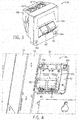
FIG. 3 is an isometric view of an exemplary network distribution adapter in accordance with an aspect of the invention; -
FIG. 4 is an isometric cutaway view of a network distribution adapter installed in the section ofFIG. 2 ; -
FIG. 5 is a cutaway side view of multiple network distribution adapters installed in the section ofFIG. 2 ; -
FIG. 6 is an isometric view of angled connectors of a network distribution adapter installed in the section ofFIG. 2 , appearing interior to the electrical system ofFIG. 1 ; and -
FIG. 7 is an isometric view of angled connectors of a network distribution adapter, according to an alternative aspect of the invention, installed in the section ofFIG. 2 , appearing interior to the electrical system ofFIG. 1 . - Referring now to
FIG. 1 , an exemplaryelectrical system 10 is provided in which electrical units 12 (such asunits electrical system 10 may be, for example, a Motor Control Center ("MCC") or other industrial, commercial, marine, or other electrical system. One example of anelectrical system 10 could be the Centerline 2100 Motor Control Center available from Rockwell Automation, Inc. In general, theelectrical system 10 may provide one or more sections 14 (such assections - The
electrical system 10 may typically receive three-phase power from an external power supply, such as a power supply grid, and/or data signals, via appropriate conduits (not shown), and distribute the received power and/or data signals to one or more of the sections 14 in various manners. The sections 14 may be electrically isolated from one another, or alternatively, may be electrically joined with other sections 14, such as via common horizontal power buses (not shown). - The units 12 may each include a door for covering an assembly of components that are supported within each unit 12 via known methods, such as screwed or snap-in engagement, thereby providing mechanical and electrical connection to the
electrical system 10. Exemplary components of the units 12 may include relays, motor starters, and Programmable Logic Controllers ("PLC's"), among others. Doors for the units 12 may include, for example, levers for operating disconnect switches, locks for preventing the doors from opening, and/or lights for indicating a safe condition for opening the doors. A latch rail (not shown) may be provided in each section 14 to interface with latches on the individual doors of the units 12. - The sections 14 may also include built-in wire-ways in which line and load wiring, cabling, and other connections may be made inside the
electrical system 10. Vertical wire-ways 16 (such as vertical wire-way 16c, for thesection 14c, as illustrated) may be disposed vertically in each section 14, adjacent to the device mounting volume for supporting the units 12. In addition, horizontal wire-ways 18 may be disposed horizontally in each section 14, such as upper horizontal wire-way 18a disposed horizontally above and adjacent to the upper most device mounting volume, and lower horizontal wire-ways 18b disposed horizontally below and adjacent to the lower most device mounting volume. - Referring now to
FIG. 2 , an isometric view of an exemplary section 14 of theelectrical system 10 is provided. The section 14 may be defined by anenclosure 20 forming a shell around the device mounting volumes 22 (such asdevice mounting volumes 22a through 22f as illustrated) for supporting the units 12. Anisolation wall 24 may separate the vertical wire-way 16 from an interior portion of the section 14 and theelectrical system 10 while still providing openings for network distribution adapters as will be further described. Also, a vertical wire-way wall 25 may separate the vertical wire-way 16 from the device mounting volumes 22 while still providingaccess areas 23 for network cables and/or other wiring to run between the vertical wire-way 16 and the device mounting volumes 22. - In one aspect, an "intelligent"
unit 12a, which could be, for example, an EtherNet/IP controlled motor in thedevice mounting volume 22a, may be installed by an end user for control via a network connection with another device. Such a network connection could be made, for example, to another device in theelectrical system 10, such as anetwork switch 27 provided in the upper horizontal wire-way 18a. One example of anetwork switch 27 could be a Stratix 5700 industrial managed Ethernet switch available from Rockwell Automation, Inc. Alternatively, such a network connection could be made to a PLC implemented in another intelligent unit in theelectrical system 10, such as theintelligent unit 12c, or to another device external to theelectrical system 10. - With additional reference to
FIG. 3 , for reliably and efficiently routing such network cables and connections, the section 14 may include one or morenetwork distribution adapters 26. Thenetwork distribution adapters 26 may be mounted to openings in theisolation wall 24 so that a network infrastructure may be pre-installed and organized, out of the way of end user cables, in the interior portion of the section 14, while an end user may simply complete the network using connections exposed in the vertical wire-way 16. Accordingly, anetwork distribution adapter 26 may vertically connect to a network cable on a side of the isolation wall 24 (within the vertical wire-way 16) that is exposed to the end user, which could then be connected to theintelligent unit 12a. In addition, thenetwork distribution adapter 26 may be pre-installed with network cables on an opposing side of the isolation wall 24 (interior to the electrical system 10) to connect to another device in theelectrical system 10, such as thenetwork switch 27 or theintelligent unit 12c (implementing a PLC), or to simply be made available in theelectrical system 10 for use elsewhere, such as in the horizontal wire-way 18.Power distribution adapters 28 may also be mounted to openings in theisolation wall 24, in the vertical wire-way 16, for similarly routing electrical power, such as 24V Direct Current (DC) power, which may be necessary for the intelligent device. - Referring now to
FIG. 4 , an isometric cutaway view of anetwork distribution adapter 26 installed in the section 14 is provided in accordance with an aspect of the invention. Thenetwork distribution adapter 26 may include ahousing 30 surrounding the device. Thehousing 30 may include two housing halves (illustrated as first andsecond housing halves FIG. 3 ) which may snap fit together. Thehousing 30 could be molded, for example, from a hardened resin, such as Valox 420SE0. Thehousing 30 may also include mounting apertures 34 (illustrated as first and second mountingapertures FIG. 3 ) for mounting thehousing 30 to the opening in theisolation wall 24. Thehousing 30 may be mounted, for example, by driving fasteners, such as self-threading screws, through the mounting apertures 34 and corresponding apertures in theisolation wall 24. Accordingly, thenetwork distribution adapter 26 may be mounted in the front of the vertical wire-way 16 to allow it to be field replaceable. Thehousing 30 could be, for example, approximately 2-1/4 inches wide by 2-1/4 inches long by 1-3/8 inches deep, and could be sloped at ahousing top 31 to include a recessed area to affix a 1.25 inches by 0.25 inch adapter port label. - A printed circuit board (PCB) 36, having top and
bottom sides housing 30. The PCB 36 may be mounted to the housing, for example, using multiple snap features 38, which could be plastic fasteners having resilience for efficiently providing secure attachment. One or more first network connectors 40 (which may be straight Ethernet connectors) may be mounted to thetop side 36a of the PCB 36. The first network connectors may each provide atop jack 42 accessible through thehousing 30. Thetop jack 42 may be, for example, an RJ-45 jack for Ethernet connections. In a preferred aspect, twofirst network connectors 40 may be provided on thetop side 36a of the PCB 36. Also, in a preferred aspect, thenetwork distribution adapter 26 may be installed so that the first network connectors 40 (and the top jacks 42) are facing downward. - With additional reference to
FIG. 5 , illustrating first and secondnetwork distribution adapters bottom side 36b of the PCB 36. Thesecond network connectors 44 may each provide abottom jack 46 accessible through thehousing 30. Thebottom jack 46 may also be, for example, an RJ-45 jack for Ethernet connections. In a preferred aspect, twosecond network connectors 44, each corresponding to afirst network connector 40, may be provided on thebottom side 36b of the PCB 36. The first andsecond network connectors network distribution adapter 26 so that they are substantially facing upward or downward as desired. The first and second connectors may be operable to display light from light emitting diodes (LED's), such as via integrated light pipes, as known in the art. - The
top jack 42 may be disposed in afirst plane 50 which may be parallel to the PCB 36 disposed in aPCB plane 52. In addition, thebottom jack 46 may be disposed in a second plane 54 (illustrated assecond plane 54a with respect to the firstnetwork distribution adapter 26a, andsecond plane 54b with respect to the secondnetwork distribution adapter 26b, inFIG. 5 ) at an angle 56 (illustrated asangle 56a with respect to the firstnetwork distribution adapter 26a, andangle 56b with respect to the secondnetwork distribution adapter 26b, inFIG. 5 ) to thefirst plane 50. - In one aspect, the angle between the first and
second planes 50 and 54 may be obtuse, such as theangle 56a between the first andsecond planes angle 56a may preferably be 135°. Accordingly, thebottom jack 46 may be accessible 135° away from thetop jack 42, such as through afirst opening 72a in theisolation wall 24. Referring briefly toFIG. 6 , thebottom jack 46, as appearing in theinterior portion 70 of the section 14, may be directed upward for accessibility, such as to the upper horizontal wire-way 18a. - In another aspect, the angle between the first and
second planes 50 and 54 may be acute, such as theangle 56b between the first andsecond planes angle 56b may preferably be 45". Accordingly, thebottom jack 46 may be accessible 45" away from thetop jack 42, such as through asecond opening 72b in theisolation wall 24. Referring briefly toFIG. 7 , thebottom jack 46, as appearing in theinterior portion 70 of the section 14, may be directed downward for accessibility, such as to the lower horizontal wire-way 18b. - As a result, the
network distribution adapters 26 may be variously configured to advantageously fit in the limited space of the vertical wire-way 16 while providing reliable protection for such network connections. In one aspect, a section 14 may accommodate, for example, up to fournetwork distribution adapters 26, which may provide up to eight connection points within the vertical wire-way 16. - Certain terminology is used herein for purposes of reference only, and thus is not intended to be limiting. For example, terms such as "upper," "lower," "above," and "below" refer to directions in the drawings to which reference is made. Terms such as "front," "back," "rear," "bottom," "side," "left" and "right" describe the orientation of portions of the component within a consistent but arbitrary frame of reference which is made clear by reference to the text and the associated drawings describing the component under discussion. Such terminology may include the words specifically mentioned above, derivatives thereof, and words of similar import. Similarly, the terms "first," "second" and other such numerical terms referring to structures do not imply a sequence or order unless clearly indicated by the context.
- When introducing elements or features of the present disclosure and the exemplary embodiments, the articles "a," "an," "the" and "said" are intended to mean that there are one or more of such elements or features. The terms "comprising," "including" and "having" are intended to be inclusive and mean that there may be additional elements or features other than those specifically noted. It is further to be understood that the method steps, processes, and operations described herein arc not to be construed as necessarily requiring their performance in the particular order discussed or illustrated, unless specifically identified as an order of performance. It is also to be understood that additional or alternative steps may be employed.
- Various features of the invention are set forth in the following claims. It should be understood that the invention is not limited in its application to the details of construction and arrangements of the components set forth herein. The invention is capable of other embodiments and of being practiced or carried out in various ways. Variations and modifications of the foregoing arc within the scope of the present invention. It also being understood that the invention disclosed and defined herein extends to all alternative combinations of two or more of the individual features mentioned or evident from the text and/or drawings. All of these different combinations constitute various alternative aspects of the present invention: The embodiments described herein explain the best modes known for practicing the invention and will enable others skilled in the art to utilize the invention. All of the publications described herein including patents and non-patent publications are hereby incorporated herein by reference in their entireties.
- The present invention may be part of a "safety system" used to protect human life and limb in a field, construction or other environment. Nevertheless, the term "safety," "safety" or "safe" as used herein is not a representation that the present invention will make the environment safe or that other systems will produce unsafe operation. Safety in such systems depends on a wide variety of factors outside of the scope of the present invention including: design of the safety system, installation and maintenance of the components of the safety system, and the cooperation and training of individuals using the safety system. Although the present invention is intended to be highly reliable, all physical systems are susceptible to failure and provision must be made for such failure.
- The following is a list of further preferred embodiments of the invention:
-
Embodiment 1. A network distribution adapter comprising:- a housing;
- a printed circuit board (PCB) mounted in the housing, the PCB having top and bottom sides;
- a first network connector mounted to the top side of the PCB, the first network connector providing a top jack accessible through the housing, the top jack being disposed in a first plane parallel to the PCB; and
- a second network connector mounted to the bottom side of the PCB, the second network connector providing a bottom jack accessible through the housing, the bottom jack being disposed in a second plane at an angle to the first plane.
- Embodiment 2. The network distribution adapter of
embodiment 1, wherein the bottom jack is disposed in the second plane at a 45° angle to the first plane so that the bottom jack is accessible 45° away from the top jack. - Embodiment 3. The network distribution adapter of
embodiment 1, wherein the bottom jack is disposed in the second plane at a 135° angle to the first plane so that the bottom jack is accessible 135° away from the top jack. - Embodiment 4. The network distribution adapter of
embodiment 1, wherein the first and second network connectors are electrically coupled via the PCB. - Embodiment 5. The network distribution adapter of
embodiment 1, wherein the first and second network connectors are RJ-45 connectors. - Embodiment 6. The network distribution adapter of
embodiment 1, wherein the PCB is mounted to the housing via a plurality of snap features. - Embodiment 7. The network distribution adapter of
embodiment 1, further comprising an aperture in the housing for mounting the housing to a wall. - Embodiment 8. The network distribution adapter of
embodiment 1, further comprising:- third and fourth network connectors,
- wherein the third network connector is mounted to the top side of the PCB adjacent to the first network connector, the third network connector providing a top jack accessible through the housing, the top jack being disposed in the first plane parallel to the PCB, and
- wherein the fourth network connector is mounted to the bottom side of the PCB adjacent to the second network connector, the fourth network connector providing a bottom jack accessible through the housing, the bottom jack being disposed in the second plane at the angle to the first plane.
- Embodiment 9. A Motor Control Center (MCC) comprising:
- an enclosure having a device mounting volume for supporting electrical units;
- a vertical wire-way disposed adjacently to the device mounting volume;
- a wall separating the vertical wire-way from an interior portion of the MCC; and
- a network distribution adapter including:
- a housing;
- a PCB mounted in the housing, the PCB having top and bottom sides;
- a first network connector mounted to the top side of the PCB, the first network connector providing a top jack accessible through the housing, the top jack being disposed in a first plane parallel to the PCB; and
- a second network connector mounted to the bottom side of the PCB, the second network connector providing a bottom jack accessible through the housing, the bottom jack being disposed in a second plane at an angle to the first plane;
- wherein the network distribution adapter is mounted to an opening in the wall so that the first network connector is accessible in the vertical wire-way and the second network connector is accessible in the interior portion of the MCC.
-
Embodiment 10. The MCC of embodiment 9, further comprising an electrical cable having first and second ends and a horizontal wire-way disposed adjacently to the device mounting volume, wherein the first end of the electrical cable is connected to the second network connector and the second end of the electrical cable is provided in the horizontal wire-way. - Embodiment 11. The MCC of
embodiment 10, further comprising a network switch in the horizontal wire-way, wherein the second end of the electrical cable is connected to the network switch. - Embodiment 12. The MCC of
embodiment 10, further comprising a second electrical cable having first and second ends, wherein the first end of the second electrical cable is connected to the first network connector and the second end of the second electrical cable is provided in the device mounting volume. - Embodiment 13. The MCC of embodiment 9, wherein the bottom jack is disposed in the second plane at a 45° angle to the first plane so that the bottom jack is accessible 45° away from the top jack.
- Embodiment 14. The MCC of embodiment 9, wherein the bottom jack is disposed in the second plane at a 135° angle to the first plane so that the bottom jack is accessible 135° away from the top jack.
- Embodiment 15. The MCC of embodiment 9, further comprising a vertical wire-way wall separating the vertical wire-way from the device mounting volume, the vertical wire-way wall having an access area for running a network cable between the vertical wire-way and the device mounting volume.
-
Embodiment 16. The MCC of embodiment 9, wherein the network distribution adapter further includes apertures in the housing for mounting the housing. - Embodiment 17. The MCC of
embodiment 16, further comprising fasteners received through the apertures, wherein the fasteners are operable to mount the housing to the wall. - Embodiment 18. The MCC of embodiment 9, wherein the network distribution adapter further includes:
- third and fourth network connectors,
- wherein the third network connector is mounted to the top side of the PCB adjacent to the first network connector, the third network connector providing a top jack accessible through the housing, the top jack being disposed in the first plane parallel to the PCB, and
- wherein the fourth network connector is mounted to the bottom side of the PCB adjacent to the second network connector, the fourth network connector providing a bottom jack accessible through the housing, the bottom jack being disposed in the second plane at the angle to the first plane.
- Embodiment 19. The MCC of embodiment 9, wherein the first and second network connectors are Ethernet connectors.
-
Embodiment 20. The MCC of embodiment 9, wherein the PCB is mounted to the housing via a plurality of snap features.
Claims (15)
- A network distribution adapter comprising:a housing;a printed circuit board (PCB) mounted in the housing, the PCB having top and bottom sides;a first network connector mounted to the top side of the PCB, the first network connector providing a top jack accessible through the housing, the top jack being disposed in a first plane parallel to the PCB; anda second network connector mounted to the bottom side of the PCB, the second network connector providing a bottom jack accessible through the housing, the bottom jack being disposed in a second plane at an angle to the first plane.
- The network distribution adapter of claim 1, wherein:the bottom jack is disposed in the second plane at a 45° angle to the first plane so that the bottom jack is accessible 45° away from the top jack; orthe bottom jack is disposed in the second plane at a 135° angle to the first plane so that the bottom jack is accessible 135° away from the top jack.
- The network distribution adapter of claim 1 or 2, wherein:the first and second network connectors are electrically coupled via the PCB; orthe first and second network connectors are RJ-45 connectors.
- The network distribution adapter of one of claims 1 to 3, wherein the PCB is mounted to the housing via a plurality of snap features.
- The network distribution adapter of one of claims 1 to 4, further comprising an aperture in the housing for mounting the housing to a wall.
- The network distribution adapter of one of claims 1 to 5, further comprising:third and fourth network connectors,wherein the third network connector is mounted to the top side of the PCB adjacent to the first network connector, the third network connector providing a top jack accessible through the housing, the top jack being disposed in the first plane parallel to the PCB, andwherein the fourth network connector is mounted to the bottom side of the PCB adjacent to the second network connector, the fourth network connector providing a bottom jack accessible through the housing, the bottom jack being disposed in the second plane at the angle to the first plane.
- A Motor Control Center (MCC) comprising:an enclosure having a device mounting volume for supporting electrical units;a vertical wire-way disposed adjacently to the device mounting volume;a wall separating the vertical wire-way from an interior portion of the MCC; anda network distribution adapter including:a housing;a PCB mounted in the housing, the PCB having top and bottom sides;a first network connector mounted to the top side of the PCB, the first network connector providing a top jack accessible through the housing, the top jack being disposed in a first plane parallel to the PCB; anda second network connector mounted to the bottom side of the PCB, the second network connector providing a bottom jack accessible through the housing, the bottom jack being disposed in a second plane at an angle to the first plane;wherein the network distribution adapter is mounted to an opening in the wall so that the first network connector is accessible in the vertical wire-way and the second network connector is accessible in the interior portion of the MCC.
- The MCC of claim 7, further comprising an electrical cable having first and second ends and a horizontal wire-way disposed adjacently to the device mounting volume, wherein the first end of the electrical cable is connected to the second network connector and the second end of the electrical cable is provided in the horizontal wire-way.
- The MCC of claim 8, further comprising:a network switch in the horizontal wire-way, wherein the second end of the electrical cable is connected to the network switch; ora second electrical cable having first and second ends, wherein the first end of the second electrical cable is connected to the first network connector and the second end of the second electrical cable is provided in the device mounting volume.
- The MCC of one of claims 7 to 9, wherein:the bottom jack is disposed in the second plane at a 45° angle to the first plane so that the bottom jack is accessible 45° away from the top jack; orthe bottom jack is disposed in the second plane at a 135° angle to the first plane so that the bottom jack is accessible 135° away from the top jack.
- The MCC of one of claims 7 to 10, further comprising a vertical wire-way wall separating the vertical wire-way from the device mounting volume, the vertical wire-way wall having an access area for running a network cable between the vertical wire-way and the device mounting volume.
- The MCC of one of claims 7 to 11, wherein the network distribution adapter further includes apertures in the housing for mounting the housing.
- The MCC of claim 12, further comprising fasteners received through the apertures, wherein the fasteners are operable to mount the housing to the wall.
- The MCC of one of claims 7 to 13, wherein the network distribution adapter further includes:third and fourth network connectors,wherein the third network connector is mounted to the top side of the PCB adjacent to the first network connector, the third network connector providing a top jack accessible through the housing, the top jack being disposed in the first plane parallel to the PCB, andwherein the fourth network connector is mounted to the bottom side of the PCB adjacent to the second network connector, the fourth network connector providing a bottom jack accessible through the housing, the bottom jack being disposed in the second plane at the angle to the first plane.
- The MCC of one of claims 7 to 14, wherein the first and second network connectors are Ethernet connectors, and/or the PCB is mounted to the housing via a plurality of snap features.
Applications Claiming Priority (1)
| Application Number | Priority Date | Filing Date | Title |
|---|---|---|---|
| US15/216,778 US9722380B1 (en) | 2016-07-22 | 2016-07-22 | Network distribution adapter for a motor control center |
Publications (2)
| Publication Number | Publication Date |
|---|---|
| EP3273758A1 true EP3273758A1 (en) | 2018-01-24 |
| EP3273758B1 EP3273758B1 (en) | 2019-08-14 |
Family
ID=59253339
Family Applications (1)
| Application Number | Title | Priority Date | Filing Date |
|---|---|---|---|
| EP17178257.6A Active EP3273758B1 (en) | 2016-07-22 | 2017-06-28 | Motor control center |
Country Status (3)
| Country | Link |
|---|---|
| US (1) | US9722380B1 (en) |
| EP (1) | EP3273758B1 (en) |
| CN (1) | CN107643723B (en) |
Families Citing this family (1)
| Publication number | Priority date | Publication date | Assignee | Title |
|---|---|---|---|---|
| US10601204B2 (en) * | 2018-02-09 | 2020-03-24 | Rockwell Automation Technologies, Inc. | Electrical unit for a motor control center with ingress protection |
Citations (4)
| Publication number | Priority date | Publication date | Assignee | Title |
|---|---|---|---|---|
| US20050282442A1 (en) * | 2004-06-18 | 2005-12-22 | Hyland James H | Electrical adapter assembly |
| GB2420665A (en) * | 2001-11-16 | 2006-05-31 | Adc Telecommunications Inc | Angled connector assembly for patch panel |
| US20070279887A1 (en) * | 2006-05-30 | 2007-12-06 | Thomas Sullivan | Wall plate assembly with integral digital extender |
| US20130022357A1 (en) * | 2010-09-30 | 2013-01-24 | Rockwell Automation Technologies, Inc. | Motor control center network connectivity method and system |
Family Cites Families (24)
| Publication number | Priority date | Publication date | Assignee | Title |
|---|---|---|---|---|
| US4817283A (en) * | 1987-08-21 | 1989-04-04 | Amp Incorporated | Method of forming a modular plug coupler |
| US4799901A (en) * | 1988-06-30 | 1989-01-24 | Pirc Douglas J | Adapter having transient suppression protection |
| US5044981A (en) * | 1990-04-18 | 1991-09-03 | Reliance Comm/Tec Corporation | Snap-on stacking telephone jack |
| DE4309039C2 (en) * | 1992-10-13 | 1995-05-04 | Metz Albert Blumberger Tel | Junction box for shielded cables, especially for data transmission cables |
| US5295869A (en) * | 1992-12-18 | 1994-03-22 | The Siemon Company | Electrically balanced connector assembly |
| US5370541A (en) * | 1993-01-25 | 1994-12-06 | Minnesota Mining And Manufacturing Company | Repositionable termination module |
| US5269708A (en) * | 1993-03-03 | 1993-12-14 | Adc Telecommunications, Inc. | Patch panel for high speed twisted pair |
| US5735714A (en) * | 1995-04-06 | 1998-04-07 | Ortronics Inc. | Information management outlet module and assembly providing protection to exposed cabling |
| US6126476A (en) * | 1998-03-23 | 2000-10-03 | The Siemon Company | Enhanced performance connector |
| FR2776426B1 (en) * | 1998-03-23 | 2000-05-26 | Framatome Connectors Int | CONNECTING ELEMENT OF TWO PLUGS, MALE AND FEMALE ELEMENTS ADAPTED AND CONNECTION DEVICE OBTAINED |
| US6361354B1 (en) * | 1998-03-23 | 2002-03-26 | The Siemon Company | Vertical and right angle modular outlets |
| TW408868U (en) * | 1999-04-23 | 2000-10-11 | Liau Sheng Shing | Flip cover type connector |
| US6431765B1 (en) * | 1999-06-11 | 2002-08-13 | Cisco Technology Inc. | Distributed network repeater module and method |
| US6383028B1 (en) * | 2000-09-27 | 2002-05-07 | Hsi-Fan Chang | Signal line adapting socket |
| US6475019B1 (en) * | 2001-07-12 | 2002-11-05 | Leviton Manufacturing Co., Inc. | Insulation displacement electrical connector |
| US6736670B2 (en) * | 2001-11-16 | 2004-05-18 | Adc Telecommunications, Inc. | Angled RJ to RJ patch panel |
| US6504726B1 (en) * | 2001-11-16 | 2003-01-07 | Adc Telecommunications, Inc. | Telecommunications patch panel |
| DE102006003752A1 (en) * | 2006-01-25 | 2007-09-20 | Mc Technology Gmbh | clutch |
| FR2906939B1 (en) * | 2006-10-09 | 2009-01-23 | Legrand France | CONNECTING DEVICE FOR LOCAL NETWORK |
| US7762839B2 (en) * | 2008-12-22 | 2010-07-27 | Surtec Industries, Inc. | Patch panel assembly |
| CA2647704A1 (en) * | 2008-12-22 | 2010-06-22 | Belden Cdt (Canada) Inc. | Coupler connector |
| US20100323546A1 (en) * | 2009-06-19 | 2010-12-23 | Applied Optical Systems, Inc. | Rugged registered jack connection |
| US7976334B2 (en) * | 2009-09-10 | 2011-07-12 | Avx Corporation | Capped insulation displacement connector (IDC) |
| US8496500B1 (en) * | 2012-02-14 | 2013-07-30 | Telebox Industries Corp. | Terminal holder structure for RJ45 dual-port jack |
-
2016
- 2016-07-22 US US15/216,778 patent/US9722380B1/en active Active
-
2017
- 2017-06-28 EP EP17178257.6A patent/EP3273758B1/en active Active
- 2017-07-06 CN CN201710546279.7A patent/CN107643723B/en active Active
Patent Citations (4)
| Publication number | Priority date | Publication date | Assignee | Title |
|---|---|---|---|---|
| GB2420665A (en) * | 2001-11-16 | 2006-05-31 | Adc Telecommunications Inc | Angled connector assembly for patch panel |
| US20050282442A1 (en) * | 2004-06-18 | 2005-12-22 | Hyland James H | Electrical adapter assembly |
| US20070279887A1 (en) * | 2006-05-30 | 2007-12-06 | Thomas Sullivan | Wall plate assembly with integral digital extender |
| US20130022357A1 (en) * | 2010-09-30 | 2013-01-24 | Rockwell Automation Technologies, Inc. | Motor control center network connectivity method and system |
Also Published As
| Publication number | Publication date |
|---|---|
| CN107643723A (en) | 2018-01-30 |
| CN107643723B (en) | 2019-12-06 |
| US9722380B1 (en) | 2017-08-01 |
| EP3273758B1 (en) | 2019-08-14 |
Similar Documents
| Publication | Publication Date | Title |
|---|---|---|
| US5574251A (en) | Electrical and electronic cabinet systems | |
| US8274782B2 (en) | Motor control center network connectivity method and system | |
| CN106992437B (en) | Power distribution cabinet | |
| US7417848B2 (en) | Multiple height, high density horizontal low voltage motor control center | |
| US8500465B1 (en) | Adaptive cable connection system | |
| EP3235103B1 (en) | Modular uninterruptible power supply and power distribution system | |
| WO2017060327A1 (en) | Power distribution module for a rack for electronic equipment | |
| US7511946B2 (en) | Vertical neutral bus and support for motor control center | |
| EP3163695B1 (en) | Fixed vertical distribution bus bar | |
| US9667051B2 (en) | Power terminal enclosure for power conductors | |
| CA2912960C (en) | Large scale automated test system reconfiguration | |
| US10601204B2 (en) | Electrical unit for a motor control center with ingress protection | |
| US9722380B1 (en) | Network distribution adapter for a motor control center | |
| US9667041B2 (en) | Electrically insulating cover for terminal assembly | |
| US20150180226A1 (en) | Multispur fieldbus isolator arrangement | |
| JP4958282B2 (en) | Breaker unit | |
| US8116070B2 (en) | Control and switchgear cabinet | |
| KR102625538B1 (en) | Relay board detachable electric vehicle charging device | |
| KR20150077020A (en) | The bus bar support apparatus for motor control center | |
| WO2017058158A1 (en) | Mounting extension bars on power distribution units | |
| CZ126796A3 (en) | Module device for electrical energy distribution |
Legal Events
| Date | Code | Title | Description |
|---|---|---|---|
| PUAI | Public reference made under article 153(3) epc to a published international application that has entered the european phase |
Free format text: ORIGINAL CODE: 0009012 |
|
| STAA | Information on the status of an ep patent application or granted ep patent |
Free format text: STATUS: THE APPLICATION HAS BEEN PUBLISHED |
|
| AK | Designated contracting states |
Kind code of ref document: A1 Designated state(s): AL AT BE BG CH CY CZ DE DK EE ES FI FR GB GR HR HU IE IS IT LI LT LU LV MC MK MT NL NO PL PT RO RS SE SI SK SM TR |
|
| AX | Request for extension of the european patent |
Extension state: BA ME |
|
| STAA | Information on the status of an ep patent application or granted ep patent |
Free format text: STATUS: REQUEST FOR EXAMINATION WAS MADE |
|
| 17P | Request for examination filed |
Effective date: 20180712 |
|
| RBV | Designated contracting states (corrected) |
Designated state(s): AL AT BE BG CH CY CZ DE DK EE ES FI FR GB GR HR HU IE IS IT LI LT LU LV MC MK MT NL NO PL PT RO RS SE SI SK SM TR |
|
| GRAP | Despatch of communication of intention to grant a patent |
Free format text: ORIGINAL CODE: EPIDOSNIGR1 |
|
| STAA | Information on the status of an ep patent application or granted ep patent |
Free format text: STATUS: GRANT OF PATENT IS INTENDED |
|
| RIC1 | Information provided on ipc code assigned before grant |
Ipc: H01R 13/66 20060101AFI20190221BHEP |
|
| RIC1 | Information provided on ipc code assigned before grant |
Ipc: H05K 7/14 20060101AFI20190304BHEP |
|
| INTG | Intention to grant announced |
Effective date: 20190321 |
|
| GRAS | Grant fee paid |
Free format text: ORIGINAL CODE: EPIDOSNIGR3 |
|
| GRAA | (expected) grant |
Free format text: ORIGINAL CODE: 0009210 |
|
| STAA | Information on the status of an ep patent application or granted ep patent |
Free format text: STATUS: THE PATENT HAS BEEN GRANTED |
|
| AK | Designated contracting states |
Kind code of ref document: B1 Designated state(s): AL AT BE BG CH CY CZ DE DK EE ES FI FR GB GR HR HU IE IS IT LI LT LU LV MC MK MT NL NO PL PT RO RS SE SI SK SM TR |
|
| REG | Reference to a national code |
Ref country code: GB Ref legal event code: FG4D |
|
| REG | Reference to a national code |
Ref country code: CH Ref legal event code: EP Ref country code: AT Ref legal event code: REF Ref document number: 1168596 Country of ref document: AT Kind code of ref document: T Effective date: 20190815 |
|
| REG | Reference to a national code |
Ref country code: IE Ref legal event code: FG4D |
|
| REG | Reference to a national code |
Ref country code: DE Ref legal event code: R096 Ref document number: 602017006061 Country of ref document: DE |
|
| REG | Reference to a national code |
Ref country code: NL Ref legal event code: MP Effective date: 20190814 |
|
| REG | Reference to a national code |
Ref country code: LT Ref legal event code: MG4D |
|
| PG25 | Lapsed in a contracting state [announced via postgrant information from national office to epo] |
Ref country code: SE Free format text: LAPSE BECAUSE OF FAILURE TO SUBMIT A TRANSLATION OF THE DESCRIPTION OR TO PAY THE FEE WITHIN THE PRESCRIBED TIME-LIMIT Effective date: 20190814 Ref country code: NL Free format text: LAPSE BECAUSE OF FAILURE TO SUBMIT A TRANSLATION OF THE DESCRIPTION OR TO PAY THE FEE WITHIN THE PRESCRIBED TIME-LIMIT Effective date: 20190814 Ref country code: BG Free format text: LAPSE BECAUSE OF FAILURE TO SUBMIT A TRANSLATION OF THE DESCRIPTION OR TO PAY THE FEE WITHIN THE PRESCRIBED TIME-LIMIT Effective date: 20191114 Ref country code: LT Free format text: LAPSE BECAUSE OF FAILURE TO SUBMIT A TRANSLATION OF THE DESCRIPTION OR TO PAY THE FEE WITHIN THE PRESCRIBED TIME-LIMIT Effective date: 20190814 Ref country code: PT Free format text: LAPSE BECAUSE OF FAILURE TO SUBMIT A TRANSLATION OF THE DESCRIPTION OR TO PAY THE FEE WITHIN THE PRESCRIBED TIME-LIMIT Effective date: 20191216 Ref country code: HR Free format text: LAPSE BECAUSE OF FAILURE TO SUBMIT A TRANSLATION OF THE DESCRIPTION OR TO PAY THE FEE WITHIN THE PRESCRIBED TIME-LIMIT Effective date: 20190814 Ref country code: FI Free format text: LAPSE BECAUSE OF FAILURE TO SUBMIT A TRANSLATION OF THE DESCRIPTION OR TO PAY THE FEE WITHIN THE PRESCRIBED TIME-LIMIT Effective date: 20190814 Ref country code: NO Free format text: LAPSE BECAUSE OF FAILURE TO SUBMIT A TRANSLATION OF THE DESCRIPTION OR TO PAY THE FEE WITHIN THE PRESCRIBED TIME-LIMIT Effective date: 20191114 |
|
| REG | Reference to a national code |
Ref country code: AT Ref legal event code: MK05 Ref document number: 1168596 Country of ref document: AT Kind code of ref document: T Effective date: 20190814 |
|
| PG25 | Lapsed in a contracting state [announced via postgrant information from national office to epo] |
Ref country code: GR Free format text: LAPSE BECAUSE OF FAILURE TO SUBMIT A TRANSLATION OF THE DESCRIPTION OR TO PAY THE FEE WITHIN THE PRESCRIBED TIME-LIMIT Effective date: 20191115 Ref country code: LV Free format text: LAPSE BECAUSE OF FAILURE TO SUBMIT A TRANSLATION OF THE DESCRIPTION OR TO PAY THE FEE WITHIN THE PRESCRIBED TIME-LIMIT Effective date: 20190814 Ref country code: IS Free format text: LAPSE BECAUSE OF FAILURE TO SUBMIT A TRANSLATION OF THE DESCRIPTION OR TO PAY THE FEE WITHIN THE PRESCRIBED TIME-LIMIT Effective date: 20191214 Ref country code: ES Free format text: LAPSE BECAUSE OF FAILURE TO SUBMIT A TRANSLATION OF THE DESCRIPTION OR TO PAY THE FEE WITHIN THE PRESCRIBED TIME-LIMIT Effective date: 20190814 Ref country code: RS Free format text: LAPSE BECAUSE OF FAILURE TO SUBMIT A TRANSLATION OF THE DESCRIPTION OR TO PAY THE FEE WITHIN THE PRESCRIBED TIME-LIMIT Effective date: 20190814 Ref country code: AL Free format text: LAPSE BECAUSE OF FAILURE TO SUBMIT A TRANSLATION OF THE DESCRIPTION OR TO PAY THE FEE WITHIN THE PRESCRIBED TIME-LIMIT Effective date: 20190814 |
|
| PG25 | Lapsed in a contracting state [announced via postgrant information from national office to epo] |
Ref country code: TR Free format text: LAPSE BECAUSE OF FAILURE TO SUBMIT A TRANSLATION OF THE DESCRIPTION OR TO PAY THE FEE WITHIN THE PRESCRIBED TIME-LIMIT Effective date: 20190814 |
|
| PG25 | Lapsed in a contracting state [announced via postgrant information from national office to epo] |
Ref country code: RO Free format text: LAPSE BECAUSE OF FAILURE TO SUBMIT A TRANSLATION OF THE DESCRIPTION OR TO PAY THE FEE WITHIN THE PRESCRIBED TIME-LIMIT Effective date: 20190814 Ref country code: IT Free format text: LAPSE BECAUSE OF FAILURE TO SUBMIT A TRANSLATION OF THE DESCRIPTION OR TO PAY THE FEE WITHIN THE PRESCRIBED TIME-LIMIT Effective date: 20190814 Ref country code: AT Free format text: LAPSE BECAUSE OF FAILURE TO SUBMIT A TRANSLATION OF THE DESCRIPTION OR TO PAY THE FEE WITHIN THE PRESCRIBED TIME-LIMIT Effective date: 20190814 Ref country code: EE Free format text: LAPSE BECAUSE OF FAILURE TO SUBMIT A TRANSLATION OF THE DESCRIPTION OR TO PAY THE FEE WITHIN THE PRESCRIBED TIME-LIMIT Effective date: 20190814 Ref country code: PL Free format text: LAPSE BECAUSE OF FAILURE TO SUBMIT A TRANSLATION OF THE DESCRIPTION OR TO PAY THE FEE WITHIN THE PRESCRIBED TIME-LIMIT Effective date: 20190814 Ref country code: DK Free format text: LAPSE BECAUSE OF FAILURE TO SUBMIT A TRANSLATION OF THE DESCRIPTION OR TO PAY THE FEE WITHIN THE PRESCRIBED TIME-LIMIT Effective date: 20190814 |
|
| PG25 | Lapsed in a contracting state [announced via postgrant information from national office to epo] |
Ref country code: IS Free format text: LAPSE BECAUSE OF FAILURE TO SUBMIT A TRANSLATION OF THE DESCRIPTION OR TO PAY THE FEE WITHIN THE PRESCRIBED TIME-LIMIT Effective date: 20200224 Ref country code: SM Free format text: LAPSE BECAUSE OF FAILURE TO SUBMIT A TRANSLATION OF THE DESCRIPTION OR TO PAY THE FEE WITHIN THE PRESCRIBED TIME-LIMIT Effective date: 20190814 Ref country code: SK Free format text: LAPSE BECAUSE OF FAILURE TO SUBMIT A TRANSLATION OF THE DESCRIPTION OR TO PAY THE FEE WITHIN THE PRESCRIBED TIME-LIMIT Effective date: 20190814 Ref country code: CZ Free format text: LAPSE BECAUSE OF FAILURE TO SUBMIT A TRANSLATION OF THE DESCRIPTION OR TO PAY THE FEE WITHIN THE PRESCRIBED TIME-LIMIT Effective date: 20190814 |
|
| REG | Reference to a national code |
Ref country code: DE Ref legal event code: R097 Ref document number: 602017006061 Country of ref document: DE |
|
| PLBE | No opposition filed within time limit |
Free format text: ORIGINAL CODE: 0009261 |
|
| STAA | Information on the status of an ep patent application or granted ep patent |
Free format text: STATUS: NO OPPOSITION FILED WITHIN TIME LIMIT |
|
| PG2D | Information on lapse in contracting state deleted |
Ref country code: IS |
|
| 26N | No opposition filed |
Effective date: 20200603 |
|
| PG25 | Lapsed in a contracting state [announced via postgrant information from national office to epo] |
Ref country code: SI Free format text: LAPSE BECAUSE OF FAILURE TO SUBMIT A TRANSLATION OF THE DESCRIPTION OR TO PAY THE FEE WITHIN THE PRESCRIBED TIME-LIMIT Effective date: 20190814 |
|
| PG25 | Lapsed in a contracting state [announced via postgrant information from national office to epo] |
Ref country code: MC Free format text: LAPSE BECAUSE OF FAILURE TO SUBMIT A TRANSLATION OF THE DESCRIPTION OR TO PAY THE FEE WITHIN THE PRESCRIBED TIME-LIMIT Effective date: 20190814 |
|
| REG | Reference to a national code |
Ref country code: CH Ref legal event code: PL |
|
| PG25 | Lapsed in a contracting state [announced via postgrant information from national office to epo] |
Ref country code: LU Free format text: LAPSE BECAUSE OF NON-PAYMENT OF DUE FEES Effective date: 20200628 |
|
| REG | Reference to a national code |
Ref country code: BE Ref legal event code: MM Effective date: 20200630 |
|
| PG25 | Lapsed in a contracting state [announced via postgrant information from national office to epo] |
Ref country code: LI Free format text: LAPSE BECAUSE OF NON-PAYMENT OF DUE FEES Effective date: 20200630 Ref country code: CH Free format text: LAPSE BECAUSE OF NON-PAYMENT OF DUE FEES Effective date: 20200630 Ref country code: IE Free format text: LAPSE BECAUSE OF NON-PAYMENT OF DUE FEES Effective date: 20200628 |
|
| PG25 | Lapsed in a contracting state [announced via postgrant information from national office to epo] |
Ref country code: BE Free format text: LAPSE BECAUSE OF NON-PAYMENT OF DUE FEES Effective date: 20200630 |
|
| PG25 | Lapsed in a contracting state [announced via postgrant information from national office to epo] |
Ref country code: MT Free format text: LAPSE BECAUSE OF FAILURE TO SUBMIT A TRANSLATION OF THE DESCRIPTION OR TO PAY THE FEE WITHIN THE PRESCRIBED TIME-LIMIT Effective date: 20190814 Ref country code: CY Free format text: LAPSE BECAUSE OF FAILURE TO SUBMIT A TRANSLATION OF THE DESCRIPTION OR TO PAY THE FEE WITHIN THE PRESCRIBED TIME-LIMIT Effective date: 20190814 |
|
| PG25 | Lapsed in a contracting state [announced via postgrant information from national office to epo] |
Ref country code: MK Free format text: LAPSE BECAUSE OF FAILURE TO SUBMIT A TRANSLATION OF THE DESCRIPTION OR TO PAY THE FEE WITHIN THE PRESCRIBED TIME-LIMIT Effective date: 20190814 |
|
| P01 | Opt-out of the competence of the unified patent court (upc) registered |
Effective date: 20230404 |
|
| PGFP | Annual fee paid to national office [announced via postgrant information from national office to epo] |
Ref country code: DE Payment date: 20250520 Year of fee payment: 9 |
|
| PGFP | Annual fee paid to national office [announced via postgrant information from national office to epo] |
Ref country code: GB Payment date: 20250520 Year of fee payment: 9 |
|
| PGFP | Annual fee paid to national office [announced via postgrant information from national office to epo] |
Ref country code: FR Payment date: 20250521 Year of fee payment: 9 |