EP3273702A1 - Housing for connecting a transducer for a substrate - Google Patents
Housing for connecting a transducer for a substrate Download PDFInfo
- Publication number
- EP3273702A1 EP3273702A1 EP16180301.0A EP16180301A EP3273702A1 EP 3273702 A1 EP3273702 A1 EP 3273702A1 EP 16180301 A EP16180301 A EP 16180301A EP 3273702 A1 EP3273702 A1 EP 3273702A1
- Authority
- EP
- European Patent Office
- Prior art keywords
- transducer
- substrate
- housing
- housing according
- main body
- Prior art date
- Legal status (The legal status is an assumption and is not a legal conclusion. Google has not performed a legal analysis and makes no representation as to the accuracy of the status listed.)
- Ceased
Links
Images

Classifications
-
- H—ELECTRICITY
- H04—ELECTRIC COMMUNICATION TECHNIQUE
- H04R—LOUDSPEAKERS, MICROPHONES, GRAMOPHONE PICK-UPS OR LIKE ACOUSTIC ELECTROMECHANICAL TRANSDUCERS; ELECTRIC HEARING AIDS; PUBLIC ADDRESS SYSTEMS
- H04R9/00—Transducers of moving-coil, moving-strip, or moving-wire type
- H04R9/06—Loudspeakers
- H04R9/066—Loudspeakers using the principle of inertia
-
- A—HUMAN NECESSITIES
- A42—HEADWEAR
- A42B—HATS; HEAD COVERINGS
- A42B3/00—Helmets; Helmet covers ; Other protective head coverings
- A42B3/04—Parts, details or accessories of helmets
- A42B3/0406—Accessories for helmets
-
- A—HUMAN NECESSITIES
- A42—HEADWEAR
- A42B—HATS; HEAD COVERINGS
- A42B3/00—Helmets; Helmet covers ; Other protective head coverings
- A42B3/04—Parts, details or accessories of helmets
- A42B3/30—Mounting radio sets or communication systems
-
- G—PHYSICS
- G10—MUSICAL INSTRUMENTS; ACOUSTICS
- G10K—SOUND-PRODUCING DEVICES; METHODS OR DEVICES FOR PROTECTING AGAINST, OR FOR DAMPING, NOISE OR OTHER ACOUSTIC WAVES IN GENERAL; ACOUSTICS NOT OTHERWISE PROVIDED FOR
- G10K9/00—Devices in which sound is produced by vibrating a diaphragm or analogous element, e.g. fog horns, vehicle hooters or buzzers
- G10K9/18—Details, e.g. bulbs, pumps, pistons, switches or casings
- G10K9/22—Mountings; Casings
-
- H—ELECTRICITY
- H04—ELECTRIC COMMUNICATION TECHNIQUE
- H04R—LOUDSPEAKERS, MICROPHONES, GRAMOPHONE PICK-UPS OR LIKE ACOUSTIC ELECTROMECHANICAL TRANSDUCERS; ELECTRIC HEARING AIDS; PUBLIC ADDRESS SYSTEMS
- H04R2440/00—Bending wave transducers covered by H04R, not provided for in its groups
- H04R2440/01—Acoustic transducers using travelling bending waves to generate or detect sound
Definitions
- the present invention relates to a housing for connecting a transducer to a substrate, and to transducer assembly comprising such a housing, and to a communication helmet comprising such a transducer assembly.
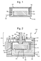
- FIG. 1 An audio transducer for converting electrical energy into sound waves.
- One such audio transducer is illustrated in Figure 1 and generally indicated at 50, where a coil 54 of conducting wire extends from a diaphragm 58 to surround but be separated from a permanent magnet 59.
- the coil 54 and diaphragm 58 are suspended on sprung arms 56 which arms 56 are affixed to a housing 53.
- the coil and diaphragm are thereby free to move relative to the magnet 59, which is fixed to the base of the housing 53.
- the coil 54 acts as an electromagnet and is alternatively repulsed and attracted to the magnetic field of the permanent magnet 59.
- the alternative repulsion and attraction causes the diaphragm to move and the movement of the diaphragm 58 relative to the magnet 53 and housing 53 generates sound waves.
- Audio transducers of this particular form may be referred to as contact transducers or surface transducers on account of their ability to be placed diaphragm down on a substrate and then transmit sound waves into the substrate.
- a housing for connecting a transducer to a substrate comprising: a main body defining a cavity for accommodating the transducer; a connecting body for connecting to the transducer and the substrate, and for covering the cavity, the connecting body comprising a protruding member for fastening to a reciprocal form in the substrate.
- Such a housing provides a robust form from which the capabilities of the transducer can be exploited. Accordingly the housing tends to enable the transducer to be used in harsh environments. Such environments could be harsh by virtue of exposure to water or moisture, or by virtue of likelihood of dynamic loading.
- the connecting body may comprise: a connecting rod having a first and second member, the first member being for fastening to the transducer, the second member being the protruding member for fastening to a reciprocal form in the substrate, the connecting rod being arranged such that the first member extends towards the cavity and the second member extends away from the cavity, a sealing plate for covering the cavity, the sealing plate comprising an aperture for allowing the second member of the connecting rod to protrude therethrough.
- the connecting rod may comprise a collar interposed between the first and second member, the collar being adapted to promote the correct positioning of the connecting rod between the main body and the sealing plate.
- Such a collar facilitates a simple assembly.
- the connecting body may define an outer surface for presenting to the substrate and wherein there is provided a gasket at the outer surface, which surrounds the protruding member.
- the gasket can be in the form of a ring surrounding the base of the protruding member.
- the main body may be provided with a channel for securely accommodating transducer cabling at an outer surface of the housing.
- Such provisions for clamping or otherwise securing the cable tend to confer a more reliable electrical connection. For instance the chance of the cable becoming detached during oscillation of the transducer, can be reduced.
- the housing may further comprise a back plate provided with a channel for accommodating transducer cabling, the back plate being attachable to the main body such that transducer cabling may be contained between the main body channel and the back plate channel.
- the protruding member for fastening to the substrate may be a threaded bolt for fastening to a threaded hole within a substrate.
- the housing can be conveniently retro-fitted to existing substrates whilst providing a reliable coupling which can tend to transfer oscillations energy efficiently from the transducer to the substrate (via the bolt).
- the threaded bolt may be adapted for fastening to a predetermined hole in a helmet, and still more particularly, may be adapted for fastening to a visor mount hole in a helmet.
- the main body may comprise a hole for allowing ingress of glue so as to secure the transducer during assembly.
- the cavity of the main body may define a ledge on which sprung arms of the transducer can attach.
- the protruding member may comprise a frangible section such that under a predetermined load, the protruding member can detach from the housing.
- Such a provision can allow the transducer housing to be sacrificially detached (by way of shearing or breaking away from the protruding member which will tend to be connected to the substrate) in the event that a certain force is applied to the housing, which would not be desirable to have transferred to the substrate.
- the protruding member may be is shorter than the depth of the reciprocal form of the substrate such that the housing abuts the substrate to provide an axial separation between the protruding member and the substrate.
- a transducer assembly comprising a housing according to the first aspect of the invention, and a transducer.
- a communication helmet comprising: a helmet for an operator; a transducer assembly according to claim 14, and being mounted on the helmet; and a radio transceiver unit mounted to an operator-wearable item and configured to feed a signal to the transducer assembly.
- FIG. 1 there is shown generally at 100 a transducer assembly.
- the transducer assembly 100 comprises an oscillatory transducer 50 installed in a housing.
- the transducer 50 comprises a planar form comprised by a flexible disc-shaped diaphragm 58 from the periphery of which extend sprung arms 56 in a generally radial direction. Extending in a generally axial direction from the planar form is a coil 54 which defines a tubular structure. Positioned within the tubular structure, but separated therefrom, is a magnet 59. The coil 54 is fed with an electrical signal by cabling 52.
- the diaphragm 58 is adapted so as to have a central aperture 55 therein.
- the housing into which the transducer is installed comprises a main body 10 and a connecting body 20.
- the main body 10 is generally cylindrical at its outer surface and is partially hollow so as to have the general form of a cap. Accordingly the main body 10 defines an internal cavity 12.
- the cavity 12 has a first section which extends initially into the body 10 and a second section, which has a smaller diameter than the first section and which continues into the body 10 up to a floor of the body 10.
- the transducer magnet 59 is attached to the floor of the body and is bonded in place with adhesive 72.
- the wall thickness of the main body 10 increases between the first and second sections of the cavity 12.
- the connecting body 20 comprises a protruding member 22.
- the connecting body 20 is fastened to the main body 10 and the transducer 50.
- the connecting body 20 is fastened to the transducer 50 at the diaphragm 58.
- the connecting body 20 comprises a connecting rod 28 and a sealing plate 24.
- the connecting rod 28 comprises a first member 21 and a second member 22.
- both of the first and second members 21, 22 are threaded cylindrical members (bolts) for fastening to a reciprocally threaded aperture or hole.
- the first member 21 extends towards and fastens to the aperture 55 of the diaphragm 58.
- the second member 22 extends in the opposite direction to the first member 21 and as such protrudes from the assembly 100 and serves to provide the protruding member.
- the connecting rod 28 further comprises a collar 23 interposed between the first and second members, which has a diameter greater than the first member 21 so as to predetermine the extent to which the first member 21 can penetrate into and/or through the diaphragm 58.
- the sealing plate 24 has the general form of a disc comprising a central aperture 26.
- the diameter of the sealing plate 24 is selected to match the diameter of the cylindrical main body 10.
- the sealing plate 24 has an outer surface 32 on an external facet of the assembly 100, and an internal surface facing the cavity 12.
- the sealing plate 24 is configured to fit over the main body so that the cavity 12 is occluded by the plate 24, but for the aperture 26, and the second member 22 of the connecting rod 28 protrudes through the aperture 26.
- the sealing plate 24 further comprises a gasket 30 which is seated into a groove in the plate 24 but protrudes from the outer surface 32 of the plate 24, albeit to a lesser extent than the second member 22.
- the gasket 30 surrounds the aperture 26 at a diameter approximately half way between the plate 24 diameter (which is substantially similar to the main body 10 diameter) and the aperture 26 diameter.
- the sealing plate 24 can be fastened to the outer wall of the main body 10 by known means such as screws or adhesive (not shown).
- the main body 10 On the opposing side of the main body 10 to the protruding member 22, the main body 10 is provided with a channel 40 which leads to a hole which communicates with the transducer coil 54. Into this channel 40 can be laid the transducer cable or wire 52.
- the transducer assembly 100 comprises a back plate 60 which is configured to fit onto the main body 10 in the region of the main body channel 40.
- the back plate 60 is provided with a channel 62 corresponding to the main body channel 40 and the back plate 60 fits over the main body 10 such that the channels 40 and 62 coincide and thereby accommodate the transducer cabling 52.
- Such accommodation acts to gently clamp the wire 52 in place and thereby to mitigate vibrations at the connection between the cable and the coil which might tend to disconnect the wire 52.
- the back plate 60 can be fastened to the main body 10 by known means such as screws or adhesive (not shown).
- the main body 10 can be formed by an additive layer manufacturing process, or otherwise by drilling out holes in a block of material.
- the transducer assembly 100 can be assembled by taking the main body 10, affixing the magnet 59 to the innermost wall (floor) using an adhesive (e.g. an epoxy), affixing the sprung arms 56 of the coil/diaphragm/arms structure to the ledge defined between the first and second sections of cavity 12, affixing the connecting rod 28 to the diaphragm 58, and affixing the sealing plate 24 to the main body 10 such that the connecting rod 28 protrudes through the sealing plate aperture 26.
- an adhesive e.g. an epoxy
- the transducer assembly 100 can be affixed by way of the protruding member 22 / second member of the connecting rod 28 to a suitably prepared substrate.
- the protruding member 22 of the transducer assembly 100 could be configured for attachment to a threaded hole in a helmet. Still further, it is contemplated for attachment to the visor mount of a helmet
- a driving electrical signal representative of an audio signal
- the transducer cable 52 which would cause the diaphragm 58 and the connecting rod 28 attached thereto to oscillate and thereby produce the audio signal.
- connecting rod 28 is connected to a substrate, that substrate will also tend to oscillate according to the audio signal.
- the wearer of the helmet will thereby be able to perceive and understand that audio signal by for instance two mechanisms. Firstly the helmet would tend to oscillate and thereby transmit air pressure waves through the wearer's ear into the auditory canal. Secondly the helmet, where it presses firmly against the wearer's skull, would tend to transmit sound directly to the inner ear through more direct oscillation of the skull (a phenomenon often referred to as bone conduction).
- the main body 10, sealing plate 24 and back plate 60 housing are made of a polyoxymethylene such as Delrin® acetal resin (as supplied by Dupont, see further details at www.dupont.com). However other materials which provide comparable or adequate hardness could be used.
- the main body 10, sealing plate 24 and back plate 60 could be formed from Aluminium or an alloy thereof.
- an alternative connecting rod 32 may be used in a housing or transducer assembly 100, replacing the connecting rod 22.
- frangible connecting rod 32 is adapted to be frangible and as such has a frangible section 34 which has the form of a narrowed neck section 36.
- a transducer assembly 100 comprising a frangible connecting rod 32 is suited for application to a substrate where sudden forces may be applied to the assembly 100 which would be undesirable to transfer to the substrate (for example where the substrate is a protective helmet).
- the frangible rod 32 can be configured to break under a predetermined load such that the frangible connecting rod 32 mitigates the risk of such loads being transferred from the transducer assembly 100 to the substrate.
- the transducer assembly 100 is shown in one particularly contemplated context where it is affixed to a helmet 300.
- the helmet 300 also has mounted on it a radio transmitter receiver 200, which is electrically connected to the feed wire 52 of the transducer 50.
- the transducer assembly 100 could be affixed to the helmet 300 whist the radio transmitter receiver 200 could be affixed elsewhere on the operator, for instance at the waist on a belt.
- the transducer assembly 100 is attached by screwing the protruding member 22 into the visor mount of the helmet 300 until the gasket 30 abuts the surface of the helmet 300 and thereby creates a seal around the aperture 26 and protruding member 22.
- the protruding member 22 may be sized with length such that it extends, even at its deepest penetration, only partially into the visor mount hole, an arrangement known as 'underflush'. In particular a space of 2 to 3 mm can be provided between the member 22 at its deepest penetration and the floor of the visor mount hole.
- the protruding member 22 tends to be prevented from breaching into the helmet 300 in the event of a force applied through the transducer assembly 100, down the protruding member 22 and towards the helmet 300.
- the radio unit 200 may receive an electromagnetic signal (which is representative of an audio signal) at an antenna, convert this to an electrical signal (again representative of the audio signal) and feed this to the transducer assembly over feed wire 42.
- an electromagnetic signal which is representative of an audio signal
- an electrical signal (again representative of the audio signal)
- feed this to the transducer assembly over feed wire 42 The provision of a feed wire 42 between the transducer assembly 100 and the radio unit 200 enables not only an electrical/audio signal but also power to be conveyed to the transducer assembly 100.
- the transducer assembly 100 may therefore comprise a battery and a charging circuit (which may be a port for a charging cable, or may be an inductive coil for interfacing with an inductive charging device).
- the radio unit 200 may apply certain transfer functions to the electrical signal so as to configure the signal for use with the transducer assembly 100.
- the radio unit 200 may limit the amplitude of the signal so as to protect the user against high power sound waves that could damage the user's hearing. Further, the radio unit 200 may apply frequency-dependent amplitude reduction or enhancement, so that the natural resonances of the helmet 300 are counterbalanced.
- the transducer assembly 100 may be provided with electronic components to perform form certain transfer functions or signal processing, and in particular may comprise a signal amplifier, a voltage regulator, and/or a low pass filter (to reduce the bass in the signal).
- radio unit 200 and transducer assembly 100 may be integrated into the same unit.
Landscapes
- Physics & Mathematics (AREA)
- Engineering & Computer Science (AREA)
- Acoustics & Sound (AREA)
- Signal Processing (AREA)
- Helmets And Other Head Coverings (AREA)
Abstract
There is disclosed here a housing for connecting an transducer to a substrate, the housing comprising a main body defining a cavity for accommodating the transducer a connecting body for connecting to the transducer and the substrate, and for covering the cavity, the connecting body comprising a protruding member for fastening to a reciprocal form in the substrate.
Description
- The present invention relates to a housing for connecting a transducer to a substrate, and to transducer assembly comprising such a housing, and to a communication helmet comprising such a transducer assembly.
- It is known to provide an audio transducer for converting electrical energy into sound waves. One such audio transducer is illustrated in
Figure 1 and generally indicated at 50, where acoil 54 of conducting wire extends from adiaphragm 58 to surround but be separated from apermanent magnet 59. Thecoil 54 anddiaphragm 58 are suspended on sprungarms 56 whicharms 56 are affixed to ahousing 53. The coil and diaphragm are thereby free to move relative to themagnet 59, which is fixed to the base of thehousing 53. When a fluctuating electrical signal is passed through thecoil 54, thecoil 54 acts as an electromagnet and is alternatively repulsed and attracted to the magnetic field of thepermanent magnet 59. The alternative repulsion and attraction causes the diaphragm to move and the movement of thediaphragm 58 relative to themagnet 53 andhousing 53 generates sound waves. - Audio transducers of this particular form may be referred to as contact transducers or surface transducers on account of their ability to be placed diaphragm down on a substrate and then transmit sound waves into the substrate.
- However, it has been determined by the applicant that the application of such contact transducers to certain substrates can raise issues.
- According to a first aspect of the invention there is provided a housing for connecting a transducer to a substrate, the housing comprising: a main body defining a cavity for accommodating the transducer; a connecting body for connecting to the transducer and the substrate, and for covering the cavity, the connecting body comprising a protruding member for fastening to a reciprocal form in the substrate.
- Such a housing provides a robust form from which the capabilities of the transducer can be exploited. Accordingly the housing tends to enable the transducer to be used in harsh environments. Such environments could be harsh by virtue of exposure to water or moisture, or by virtue of likelihood of dynamic loading.
- The connecting body may comprise: a connecting rod having a first and second member, the first member being for fastening to the transducer, the second member being the protruding member for fastening to a reciprocal form in the substrate, the connecting rod being arranged such that the first member extends towards the cavity and the second member extends away from the cavity, a sealing plate for covering the cavity, the sealing plate comprising an aperture for allowing the second member of the connecting rod to protrude therethrough.
- The provision of a two part connecting body allows for a readily manufactured and assembled connecting body.
- The connecting rod may comprise a collar interposed between the first and second member, the collar being adapted to promote the correct positioning of the connecting rod between the main body and the sealing plate.
- Such a collar facilitates a simple assembly.
- The connecting body may define an outer surface for presenting to the substrate and wherein there is provided a gasket at the outer surface, which surrounds the protruding member.
- Such a provision tends to enable a water-tight seal to be provided once the housing is applied to a substrate. In particular, the gasket can be in the form of a ring surrounding the base of the protruding member.
- The main body may be provided with a channel for securely accommodating transducer cabling at an outer surface of the housing.
- Such provisions for clamping or otherwise securing the cable tend to confer a more reliable electrical connection. For instance the chance of the cable becoming detached during oscillation of the transducer, can be reduced.
- Indeed the housing may further comprise a back plate provided with a channel for accommodating transducer cabling, the back plate being attachable to the main body such that transducer cabling may be contained between the main body channel and the back plate channel.
- The protruding member for fastening to the substrate may be a threaded bolt for fastening to a threaded hole within a substrate.
- As such the housing can be conveniently retro-fitted to existing substrates whilst providing a reliable coupling which can tend to transfer oscillations energy efficiently from the transducer to the substrate (via the bolt).
- Further, the threaded bolt may be adapted for fastening to a predetermined hole in a helmet, and still more particularly, may be adapted for fastening to a visor mount hole in a helmet.
- The main body may comprise a hole for allowing ingress of glue so as to secure the transducer during assembly.
- Such a provision helps facilitate manufacture and assembly.
- The cavity of the main body may define a ledge on which sprung arms of the transducer can attach.
- Such a provision helps facilitate manufacture and assembly.
- The protruding member may comprise a frangible section such that under a predetermined load, the protruding member can detach from the housing.
- Such a provision can allow the transducer housing to be sacrificially detached (by way of shearing or breaking away from the protruding member which will tend to be connected to the substrate) in the event that a certain force is applied to the housing, which would not be desirable to have transferred to the substrate.
- The protruding member may be is shorter than the depth of the reciprocal form of the substrate such that the housing abuts the substrate to provide an axial separation between the protruding member and the substrate.
- Thus the transmittance of forces from the housing to the substrate, along the axis of the protruding member such that the protruding member may breach the substrate, can be mitigated.
- According to a second aspect of the invention there is provided a transducer assembly comprising a housing according to the first aspect of the invention, and a transducer.
- According to a third aspect of the invention there is provided a communication helmet comprising: a helmet for an operator; a transducer assembly according to claim 14, and being mounted on the helmet; and a radio transceiver unit mounted to an operator-wearable item and configured to feed a signal to the transducer assembly.
- So that the invention may be well understood, at least one exemplary embodiment thereof will not be described and with reference to the following figures, of which:
-
Figure 1 shows a known transducer; -
Figure 2 shows a transducer assembly according to the present invention; -
Figure 3 shows an alternative connecting rod for a transducer assembly such as shown inFigure 2 ; and -
Figure 4 shows a transducer assembly, such as shown inFigure 2 , attached to a helmet. - Referring to
Figure 2 there is shown generally at 100 a transducer assembly. - The
transducer assembly 100 comprises anoscillatory transducer 50 installed in a housing. - The
transducer 50 comprises a planar form comprised by a flexible disc-shaped diaphragm 58 from the periphery of which extend sprungarms 56 in a generally radial direction. Extending in a generally axial direction from the planar form is acoil 54 which defines a tubular structure. Positioned within the tubular structure, but separated therefrom, is amagnet 59. Thecoil 54 is fed with an electrical signal by cabling 52. - The
diaphragm 58 is adapted so as to have acentral aperture 55 therein. - The housing into which the transducer is installed comprises a
main body 10 and a connectingbody 20. - The
main body 10 is generally cylindrical at its outer surface and is partially hollow so as to have the general form of a cap. Accordingly themain body 10 defines aninternal cavity 12. Thecavity 12 has a first section which extends initially into thebody 10 and a second section, which has a smaller diameter than the first section and which continues into thebody 10 up to a floor of thebody 10. Thetransducer magnet 59 is attached to the floor of the body and is bonded in place with adhesive 72. At the transition between the first and second sections of the cavity there is a step as the diameter between sections changes abruptly, or in alternative language, the wall thickness of themain body 10 increases between the first and second sections of thecavity 12. - The connecting
body 20 comprises a protrudingmember 22. The connectingbody 20 is fastened to themain body 10 and thetransducer 50. In particular, the connectingbody 20 is fastened to thetransducer 50 at thediaphragm 58. - Further, the connecting
body 20 comprises a connectingrod 28 and asealing plate 24. - The connecting
rod 28 comprises afirst member 21 and asecond member 22. In the present embodiment both of the first andsecond members - The
first member 21 extends towards and fastens to theaperture 55 of thediaphragm 58. Thesecond member 22 extends in the opposite direction to thefirst member 21 and as such protrudes from theassembly 100 and serves to provide the protruding member. - The connecting
rod 28 further comprises acollar 23 interposed between the first and second members, which has a diameter greater than thefirst member 21 so as to predetermine the extent to which thefirst member 21 can penetrate into and/or through thediaphragm 58. - The
sealing plate 24 has the general form of a disc comprising acentral aperture 26. The diameter of the sealingplate 24 is selected to match the diameter of the cylindricalmain body 10. The sealingplate 24 has anouter surface 32 on an external facet of theassembly 100, and an internal surface facing thecavity 12. - Moreover, the sealing
plate 24 is configured to fit over the main body so that thecavity 12 is occluded by theplate 24, but for theaperture 26, and thesecond member 22 of the connectingrod 28 protrudes through theaperture 26. - The sealing
plate 24 further comprises agasket 30 which is seated into a groove in theplate 24 but protrudes from theouter surface 32 of theplate 24, albeit to a lesser extent than thesecond member 22. Thegasket 30 surrounds theaperture 26 at a diameter approximately half way between theplate 24 diameter (which is substantially similar to themain body 10 diameter) and theaperture 26 diameter. - The sealing
plate 24 can be fastened to the outer wall of themain body 10 by known means such as screws or adhesive (not shown). - On the opposing side of the
main body 10 to the protrudingmember 22, themain body 10 is provided with achannel 40 which leads to a hole which communicates with thetransducer coil 54. Into thischannel 40 can be laid the transducer cable orwire 52. - Further, the
transducer assembly 100 comprises aback plate 60 which is configured to fit onto themain body 10 in the region of themain body channel 40. Theback plate 60 is provided with achannel 62 corresponding to themain body channel 40 and theback plate 60 fits over themain body 10 such that thechannels transducer cabling 52. Such accommodation acts to gently clamp thewire 52 in place and thereby to mitigate vibrations at the connection between the cable and the coil which might tend to disconnect thewire 52. - The
back plate 60 can be fastened to themain body 10 by known means such as screws or adhesive (not shown). - The
main body 10 can be formed by an additive layer manufacturing process, or otherwise by drilling out holes in a block of material. - The
transducer assembly 100 can be assembled by taking themain body 10, affixing themagnet 59 to the innermost wall (floor) using an adhesive (e.g. an epoxy), affixing the sprungarms 56 of the coil/diaphragm/arms structure to the ledge defined between the first and second sections ofcavity 12, affixing the connectingrod 28 to thediaphragm 58, and affixing the sealingplate 24 to themain body 10 such that the connectingrod 28 protrudes through the sealingplate aperture 26. - Thus assembled, the
transducer assembly 100 can be affixed by way of the protrudingmember 22 / second member of the connectingrod 28 to a suitably prepared substrate. - In particular, it is contemplated that the protruding
member 22 of thetransducer assembly 100 could be configured for attachment to a threaded hole in a helmet. Still further, it is contemplated for attachment to the visor mount of a helmet - In operation a driving electrical signal, representative of an audio signal, would be applied to the
transducer cable 52 which would cause thediaphragm 58 and the connectingrod 28 attached thereto to oscillate and thereby produce the audio signal. - Further, where the connecting
rod 28 is connected to a substrate, that substrate will also tend to oscillate according to the audio signal. - Where the substrate is a helmet, the wearer of the helmet will thereby be able to perceive and understand that audio signal by for instance two mechanisms. Firstly the helmet would tend to oscillate and thereby transmit air pressure waves through the wearer's ear into the auditory canal. Secondly the helmet, where it presses firmly against the wearer's skull, would tend to transmit sound directly to the inner ear through more direct oscillation of the skull (a phenomenon often referred to as bone conduction).
- The
main body 10, sealingplate 24 and backplate 60 housing are made of a polyoxymethylene such as Delrin® acetal resin (as supplied by Dupont, see further details at www.dupont.com). However other materials which provide comparable or adequate hardness could be used. For instance, themain body 10, sealingplate 24 and backplate 60 could be formed from Aluminium or an alloy thereof. - As shown in
figure 3 , analternative connecting rod 32 may be used in a housing ortransducer assembly 100, replacing the connectingrod 22. - The alternative, frangible connecting
rod 32 is adapted to be frangible and as such has afrangible section 34 which has the form of a narrowedneck section 36. - A
transducer assembly 100 comprising a frangible connectingrod 32 is suited for application to a substrate where sudden forces may be applied to theassembly 100 which would be undesirable to transfer to the substrate (for example where the substrate is a protective helmet). - Accordingly the
frangible rod 32 can be configured to break under a predetermined load such that the frangible connectingrod 32 mitigates the risk of such loads being transferred from thetransducer assembly 100 to the substrate. - Referring to
Figure 4 , thetransducer assembly 100 is shown in one particularly contemplated context where it is affixed to ahelmet 300. Thehelmet 300 also has mounted on it aradio transmitter receiver 200, which is electrically connected to thefeed wire 52 of thetransducer 50. However in alternative scenarios, thetransducer assembly 100 could be affixed to thehelmet 300 whist theradio transmitter receiver 200 could be affixed elsewhere on the operator, for instance at the waist on a belt. - The
transducer assembly 100 is attached by screwing the protrudingmember 22 into the visor mount of thehelmet 300 until thegasket 30 abuts the surface of thehelmet 300 and thereby creates a seal around theaperture 26 and protrudingmember 22. The protrudingmember 22 may be sized with length such that it extends, even at its deepest penetration, only partially into the visor mount hole, an arrangement known as 'underflush'. In particular a space of 2 to 3 mm can be provided between themember 22 at its deepest penetration and the floor of the visor mount hole. Thus the protrudingmember 22 tends to be prevented from breaching into thehelmet 300 in the event of a force applied through thetransducer assembly 100, down the protrudingmember 22 and towards thehelmet 300. - In use the
radio unit 200 may receive an electromagnetic signal (which is representative of an audio signal) at an antenna, convert this to an electrical signal (again representative of the audio signal) and feed this to the transducer assembly over feed wire 42. The provision of a feed wire 42 between thetransducer assembly 100 and theradio unit 200 enables not only an electrical/audio signal but also power to be conveyed to thetransducer assembly 100. - In alternative embodiments, there may be a wireless communication link between the
radio transmitter receiver 200 and thetransducer assembly 100. In such cases a local power supply can be integrated into thetransducer assembly 100. In particular, thetransducer assembly 100 may therefore comprise a battery and a charging circuit (which may be a port for a charging cable, or may be an inductive coil for interfacing with an inductive charging device). - The
radio unit 200 may apply certain transfer functions to the electrical signal so as to configure the signal for use with thetransducer assembly 100. - For instance the
radio unit 200 may limit the amplitude of the signal so as to protect the user against high power sound waves that could damage the user's hearing. Further, theradio unit 200 may apply frequency-dependent amplitude reduction or enhancement, so that the natural resonances of thehelmet 300 are counterbalanced. - Additionally or alternatively, the
transducer assembly 100 may be provided with electronic components to perform form certain transfer functions or signal processing, and in particular may comprise a signal amplifier, a voltage regulator, and/or a low pass filter (to reduce the bass in the signal). - In an alternative arrangement the
radio unit 200 andtransducer assembly 100 may be integrated into the same unit.
Claims (15)
- A housing for connecting a transducer to a substrate, the housing comprising:A main body defining a cavity for accommodating the transducer; andA connecting body for connecting to the transducer and the substrate, and for covering the cavity,the connecting body comprising a protruding member for fastening to a reciprocal form in the substrate.
- A housing according to claim 1 wherein the connecting body comprises:A connecting rod having a first and second member, the first member being for fastening to the transducer, the second member being the protruding member for fastening to a reciprocal form in the substrate, the connecting rod being arranged such that the first member extends towards the cavity and the second member extends away from the cavity,A sealing plate for covering the cavity, the sealing plate comprising an aperture for allowing the second member of the connecting rod to protrude therethrough.
- A housing according to claim 2 wherein the connecting rod comprises a collar interposed between the first and second member, the collar being adapted to promote the correct positioning of the connecting rod between the main body and the sealing plate.
- A housing according to any one of the preceding claims wherein the connecting body defines an outer surface for presenting to the substrate and wherein there is provided a gasket at the outer surface, which surrounds the protruding member.
- A housing according to any one of the preceding claims wherein the main body is provided with a channel for securely accommodating transducer cabling at an outer surface of the housing.
- A housing according to claim 5 further comprising a back plate provided with a channel for accommodating transducer cabling, the back plate being attachable to the main body such that transducer cabling may be contained between the main body channel and the back plate channel.
- A housing according to any one of the preceding claims wherein the protruding member for fastening to the substrate is a threaded bolt for fastening to a threaded hole within a substrate.
- A housing according to claim 7 wherein the threaded bolt is adapted for fastening to a predetermined hole in a helmet.
- A housing according to claim 8 wherein the threaded bolt is adapted for fastening to a visor mount hole in a helmet.
- A housing according to any one of the preceding claims wherein the main body comprises a hole for allowing ingress of glue so as to secure the transducer during assembly.
- A housing according to any one of the preceding claims wherein the cavity of the main body defines a ledge on which sprung arms of the transducer can attach.
- A housing according to any one of the preceding claims wherein the protruding member comprises a frangible section such that under a predetermined load, the protruding member can detach from the housing.
- A housing according to any one of the preceding claims wherein the protruding member is shorter than the depth of the reciprocal form of the substrate such that the housing abuts the substrate to provide an axial separation between the protruding member and the substrate.
- A transducer assembly comprising:A housing according to any one of the preceding claims, andA transducer.
- A communication helmet comprising:A helmet for an operator;A transducer assembly according to claim 14, and being mounted on the helmet; andA radio transceiver unit mounted to an operator-wearable item and configured to feed a signal to the transducer assembly.
Priority Applications (2)
| Application Number | Priority Date | Filing Date | Title |
|---|---|---|---|
| EP16180301.0A EP3273702A1 (en) | 2016-07-20 | 2016-07-20 | Housing for connecting a transducer for a substrate |
| PCT/GB2017/051990 WO2018015711A1 (en) | 2016-07-20 | 2017-07-06 | Housing for connecting a transducer to a substrate |
Applications Claiming Priority (1)
| Application Number | Priority Date | Filing Date | Title |
|---|---|---|---|
| EP16180301.0A EP3273702A1 (en) | 2016-07-20 | 2016-07-20 | Housing for connecting a transducer for a substrate |
Publications (1)
| Publication Number | Publication Date |
|---|---|
| EP3273702A1 true EP3273702A1 (en) | 2018-01-24 |
Family
ID=56550720
Family Applications (1)
| Application Number | Title | Priority Date | Filing Date |
|---|---|---|---|
| EP16180301.0A Ceased EP3273702A1 (en) | 2016-07-20 | 2016-07-20 | Housing for connecting a transducer for a substrate |
Country Status (1)
| Country | Link |
|---|---|
| EP (1) | EP3273702A1 (en) |
Cited By (1)
| Publication number | Priority date | Publication date | Assignee | Title |
|---|---|---|---|---|
| CN116847236A (en) * | 2021-10-22 | 2023-10-03 | 深圳市韶音科技有限公司 | a kind of earphone |
Citations (5)
| Publication number | Priority date | Publication date | Assignee | Title |
|---|---|---|---|---|
| US3430007A (en) * | 1966-03-16 | 1969-02-25 | Rolen Diversified Investors In | Dynamic transducer with wall mounted diaphragm |
| US3524027A (en) * | 1967-05-04 | 1970-08-11 | Rolen Diversified Investors In | Sound transducer with wall mounted diaphragm |
| US4914750A (en) * | 1987-07-13 | 1990-04-03 | Avm Hess, Inc. | Sound transducer |
| JPH0937536A (en) * | 1995-07-14 | 1997-02-07 | Uinberu:Kk | Oscillation converter in voice transmission system |
| EP1341362A2 (en) * | 2002-02-27 | 2003-09-03 | Hosiden Besson Limited | Hands free audio kit for helmet wearers |
-
2016
- 2016-07-20 EP EP16180301.0A patent/EP3273702A1/en not_active Ceased
Patent Citations (5)
| Publication number | Priority date | Publication date | Assignee | Title |
|---|---|---|---|---|
| US3430007A (en) * | 1966-03-16 | 1969-02-25 | Rolen Diversified Investors In | Dynamic transducer with wall mounted diaphragm |
| US3524027A (en) * | 1967-05-04 | 1970-08-11 | Rolen Diversified Investors In | Sound transducer with wall mounted diaphragm |
| US4914750A (en) * | 1987-07-13 | 1990-04-03 | Avm Hess, Inc. | Sound transducer |
| JPH0937536A (en) * | 1995-07-14 | 1997-02-07 | Uinberu:Kk | Oscillation converter in voice transmission system |
| EP1341362A2 (en) * | 2002-02-27 | 2003-09-03 | Hosiden Besson Limited | Hands free audio kit for helmet wearers |
Cited By (1)
| Publication number | Priority date | Publication date | Assignee | Title |
|---|---|---|---|---|
| CN116847236A (en) * | 2021-10-22 | 2023-10-03 | 深圳市韶音科技有限公司 | a kind of earphone |
Similar Documents
| Publication | Publication Date | Title |
|---|---|---|
| EP3186981B1 (en) | Suspended components in auditory prostheses | |
| CN109511043B (en) | A bone conduction speaker and a bone conduction sound emitting device | |
| US20070053536A1 (en) | Hearing aid system | |
| US8363870B2 (en) | Vibrator | |
| CA1208757A (en) | Tactile stimulation device for facilitating speech training of hearing-impaired individuals | |
| EP1972179B1 (en) | Hearing aid system | |
| US8520867B2 (en) | Embedded audiphone | |
| EP2592848B1 (en) | Acoustic transmission method and listening device. | |
| US9942672B2 (en) | Devices for enhancing transmissions of stimuli in auditory prostheses | |
| US10362411B2 (en) | Hearing device with fixation arrangement | |
| AU2013201322B2 (en) | An Acoustical Transmission Means and Method for Transmitting Sound | |
| CN109996153B (en) | Bone conduction hearing aid with air gap adjusting mechanism | |
| GB2552467A (en) | Housing for connecting a transducer to a substrate | |
| EP3736906B1 (en) | An antenna configuration for a hearing aid system | |
| WO2018015711A1 (en) | Housing for connecting a transducer to a substrate | |
| JPH0937536A (en) | Oscillation converter in voice transmission system | |
| US7809147B2 (en) | Osseous conduction acoustic transducer | |
| CN212752586U (en) | Bone conduction earphone | |
| US10165377B2 (en) | Hearing device | |
| CN112399318A (en) | Percutaneous bone-anchored hearing aid with improved packaging | |
| JPS6362955B2 (en) | ||
| EP4171071A1 (en) | Bone anchored hearing implant device, hearing device system and signal processing method | |
| KR20090096266A (en) | Speaker with bone conduction function | |
| KR101972002B1 (en) | Vibrational transducer for display panel | |
| JPS6328560B2 (en) |
Legal Events
| Date | Code | Title | Description |
|---|---|---|---|
| PUAI | Public reference made under article 153(3) epc to a published international application that has entered the european phase |
Free format text: ORIGINAL CODE: 0009012 |
|
| AK | Designated contracting states |
Kind code of ref document: A1 Designated state(s): AL AT BE BG CH CY CZ DE DK EE ES FI FR GB GR HR HU IE IS IT LI LT LU LV MC MK MT NL NO PL PT RO RS SE SI SK SM TR |
|
| AX | Request for extension of the european patent |
Extension state: BA ME |
|
| 18R | Application refused |
Effective date: 20180215 |