EP3273591A1 - Capacitive actuator motor, capacitive actuator, and capacitive actuator unit - Google Patents
Capacitive actuator motor, capacitive actuator, and capacitive actuator unit Download PDFInfo
- Publication number
- EP3273591A1 EP3273591A1 EP15885599.9A EP15885599A EP3273591A1 EP 3273591 A1 EP3273591 A1 EP 3273591A1 EP 15885599 A EP15885599 A EP 15885599A EP 3273591 A1 EP3273591 A1 EP 3273591A1
- Authority
- EP
- European Patent Office
- Prior art keywords
- motor
- actuator
- output
- thrust
- capacitive
- Prior art date
- Legal status (The legal status is an assumption and is not a legal conclusion. Google has not performed a legal analysis and makes no representation as to the accuracy of the status listed.)
- Granted
Links
Images





Classifications
-
- H—ELECTRICITY
- H02—GENERATION; CONVERSION OR DISTRIBUTION OF ELECTRIC POWER
- H02N—ELECTRIC MACHINES NOT OTHERWISE PROVIDED FOR
- H02N2/00—Electric machines in general using piezoelectric effect, electrostriction or magnetostriction
- H02N2/02—Electric machines in general using piezoelectric effect, electrostriction or magnetostriction producing linear motion, e.g. actuators; Linear positioners ; Linear motors
- H02N2/04—Constructional details
- H02N2/043—Mechanical transmission means, e.g. for stroke amplification
-
- H—ELECTRICITY
- H02—GENERATION; CONVERSION OR DISTRIBUTION OF ELECTRIC POWER
- H02N—ELECTRIC MACHINES NOT OTHERWISE PROVIDED FOR
- H02N1/00—Electrostatic generators or motors using a solid moving electrostatic charge carrier
-
- H—ELECTRICITY
- H02—GENERATION; CONVERSION OR DISTRIBUTION OF ELECTRIC POWER
- H02N—ELECTRIC MACHINES NOT OTHERWISE PROVIDED FOR
- H02N1/00—Electrostatic generators or motors using a solid moving electrostatic charge carrier
- H02N1/002—Electrostatic motors
- H02N1/006—Electrostatic motors of the gap-closing type
-
- H—ELECTRICITY
- H02—GENERATION; CONVERSION OR DISTRIBUTION OF ELECTRIC POWER
- H02N—ELECTRIC MACHINES NOT OTHERWISE PROVIDED FOR
- H02N2/00—Electric machines in general using piezoelectric effect, electrostriction or magnetostriction
- H02N2/02—Electric machines in general using piezoelectric effect, electrostriction or magnetostriction producing linear motion, e.g. actuators; Linear positioners ; Linear motors
Definitions
- the present invention relates to a capacitive actuator motor, a capacitive actuator, and a capacitive actuator unit.
- a multi-pair buckling actuator which moves on an entirely linear rail including an upper surface having a periodic wave-shaped contour in a side view is known (for example, refer to PTL 1).
- the multi-pair buckling actuator includes a buckling mechanism which is a displacement expansion mechanism which expands extensions of a pair of piezoelectric elements disposed so as to face each other in a straight line in an output direction perpendicular to the extension direction and outputs the extension as displacement of an output portion.
- the buckling mechanism generates a thrust by pressing the output portion displaced in an output direction to a rail.
- the thrust can be generated only in a case where the above-described multi-pair buckling actuator presses the output portion of the buckling mechanism to the rail. Accordingly, the thrust cannot be generated in a case where the output portion is away from the rail. Therefore, it is not possible to sufficiently use energy which can be output by the piezoelectric element.
- a capacitive actuator motor including: a capacitive actuator including a plurality of actuator units; and a motor output cam including a periodic shape portion, in which each of the plurality of actuator units includes a displacement expansion mechanism configured to convert an output of an expandable element having capacitive properties and urge an output transmission portion in a predetermined output direction and urging means configured to urge the output transmission portion with a certain characteristic in a direction in which the periodic shape portion and output transmission portion come into contact with each other.
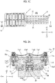
- Figs. 1A to 1C are views showing a configuration example of a capacitive actuator motor 100 according to an embodiment of the present invention.
- Fig. 1A is a perspective view of the capacitive actuator motor 100
- Fig. 1B is a side view of the capacitive actuator motor 100
- Fig. 1C is a top view of the capacitive actuator motor 100.
- Figs. 2A and 2B are views showing a configuration example of a main portion of the capacitive actuator motor 100 in Figs. 1A to 1C .
- Figs. 1A is a perspective view of the capacitive actuator motor 100
- Fig. 1B is a side view of the capacitive actuator motor 100
- Fig. 1C is a top view of the capacitive actuator motor 100.
- Figs. 2A and 2B are views showing a configuration example of a main portion of the capacitive actuator motor 100 in Figs. 1A to 1C .
- Figs. 1A is a
- FIG. 2A is a view of when a cross section shown by a one-dot chain line of Fig. 1B is viewed in a IIA direction
- Figs. 2B is a view of when a cross section shown by a one-dot chain line of Fig. 1C is viewed in a IIB direction.
- the capacitive actuator motor 100 mainly includes a capacitive actuator 1 and a motor output cam 2.
- the capacitive actuator 1 is an actuator which generates a drive force using an expandable element having capacitive properties, and mainly includes a motor frame 10, actuator units 11, motor guides 12, and expansion output linear guides 13.
- the expandable element having capacitive properties is a piezoelectric element.
- the expandable element may be a hydraulic cylinder, a pneumatic cylinder, or the like.
- the motor frame 10 is a functional element which bundles each of the plurality of actuator units 11.
- the motor frame 10 is a frame-shaped member in a top view and each of six actuator units 11 is fixed to the inner portion of the frame.
- Each of the actuator units 11 is a drive unit which configures the capacitive actuator 1.
- the actuator unit 11 mainly includes a buckling displacement expansion mechanism 11a, an output joint 11b, spring preload adjustment mechanisms 11c, piezo preload adjustment mechanisms 11d, and an outer shell 11e.
- the buckling displacement expansion mechanism 11a is a mechanism which expands displacement of the expandable element using a buckling phenomenon.
- the buckling displacement expansion mechanism 11a mainly includes a pair of piezoelectric elements 11a1, a pair of fixation portions 11a2, an output portion 11a3, and a preload adjustment spring 11a4.
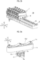
- Fig. 3A is a perspective view of the actuator unit 11
- Fig. 3B is a perspective view of the actuator unit 11 in a state where a portion of the outer shell 11e is cut out.
- Fig. 3C is a sectional view showing the pair of piezoelectric elements 11a1, the pair of fixation portions 11a2, and the output portion 11a3.
- each of the pair of piezoelectric elements 11a1 is connected to the fixation portion 11a2 via a rolling joint and the other end thereof is connected to the output portion 11a3 via a rolling joint.
- the piezoelectric element 11a1 is configured of laminated ceramics. As shown in Fig.
- the rolling joint means a connection via a rolling contact between an end spherical surface of a cap CP1 positioned on the left end of the left piezoelectric element 11a1 and an end spherical surface of the left fixation portion 11a2 and a connection via a rolling contact between an end spherical surface of a cap CP2 positioned on the right end of the left piezoelectric element 11a1 and the left end spherical surface of the output portion 11a3.
- 3C indicates a circle including a contour of the end spherical surface of the left fixation portion 11a2
- a circle C2 indicates a circle including contours of the end spherical surfaces of the caps CP1 and CP2
- a circle C3 indicates a contour of the left end spherical surface of the output portion 11a3.
- the right piezoelectric element 11a1 is also similar.
- the piezoelectric element 11a1 extends in a longitudinal direction (Y axis direction) to generate a buckling phenomenon and displaces the output portion 11a3 in a direction (Z axis direction) orthogonal to the longitudinal direction by displacement which is larger than the displacement of the extension.
- the buckling displacement expansion mechanism 11a converts an output of each of the pair of piezoelectric elements 11a1, and urges and displaces the output portion 11a3 in a predetermined output direction.
- the displacement of the output portion 11a3 is referred to as an "expansion output".
- Each of the pair of fixation portions 11a2 is a member which is fixed to the motor frame 10.
- the fixation portions 11a2 are fastened and fixed to the motor frame 10.
- the output portion 11a3 is a function element which transmits the output of the buckling displacement expansion mechanism 11a to the outside.
- the end portion on the +Z side is connected to the preload adjustment spring 11a4 and the end portion on the -Z side is connected to the output joint 11b.
- the preload adjustment spring 11a4 is an example of urging means which urges the output portion 11a3 of the buckling displacement expansion mechanism 11a with a certain characteristic.
- the preload adjustment spring 11a4 urges the output portion 11a3 in a direction in which the motor output cam 2 and the output joint 11b come into contact with each other and adjusts a displacement-thrust characteristic which is a relationship between the expansion output of the output portion 11a3 and a thrust caused by the expansion output.
- the preload adjustment spring 11a4 is configured of a plate spring including a pair of curved portions which is curved to bulge in the -Z direction, a center portion of the preload adjustment spring 11a4 is fixed to the output portion 11a3, and both end portions thereof are connected to the pair of fixation portions 11a2 via the spring preload adjustment mechanism 11c.
- the preload adjustment spring 11a4 generates a force in the Z axis direction which offsets the thrust caused by the expansion output of the output portion 11a3.
- the force generated by the preload adjustment spring 11a4 is referred to as an "offset force".
- the output joint 11b is an example of an output transmission portion which transmits the output of the buckling displacement expansion mechanism 11a to the motor output cam 2.
- the output joint 11b mainly includes a follower roller 11b1 and roller bearings 11b2, presses the follower roller 11b1 to a periodic shape portion 20 of the motor output cam 2, and thus, transmits the expansion output of the output portion 11a3 to the motor output cam 2.
- the follower roller 11b1 is a member which comes into roll-contact with the periodic shape portion 20 of the motor output cam 2.
- each of the roller bearings 11b2 is a member which rotatably supports the follower roller 11b1 around a rotation axis extending in the Y axis direction.
- the spring preload adjustment mechanism 11c is a mechanism which adjusts an offset force by the preload adjustment spring 11a4.
- the spring preload adjustment mechanism 11c is configured of a wedge block. A user adjusts the positions of both end portions of the preload adjustment spring 11a4 in the Z axis direction, and thus, can adjust an offset force which is the force by which the center portion of the preload adjustment spring 11a4 presses the output portion 11a3 in the -Z direction.
- the piezo preload adjustment mechanism 11d is a mechanism which performs application and adjustment of a preload with respect to four rolling joints in the buckling displacement expansion mechanism 11a.
- the piezo preload adjustment mechanism 11d includes the cap CP1, a guide GD1, and a shim SH1.
- the cap CP1 is a member which is attached to the left end of the left piezoelectric element 11a1 in order to configure the rolling joint between the left piezoelectric element 11a1 and the left fixation portion 11a2.
- the guide GD1 is a member which guides the cap CP1 to be detachably attached to the left end of the left piezoelectric element 11a1, and is fixed to the cap CP1.
- the cap CP1 and the shim SH1 are configured so as to transmit the thrust generated by the piezoelectric element 11a1 with high efficiency.
- the cap CP1 and the shim SH1 are formed of a material having high elasticity and strength such as a steel material or ceramics.
- the guide GD1 is configured so as to secure alignment of the caps CP1 and CP2 and the piezoelectric element 11a1 and protect an outer surface of the piezoelectric element 11a1. Therefore, preferably, the guide GD1 is formed of a material having lower elasticity than that of the piezoelectric element 11a1 or has a structure of low elasticity.
- the cap CP1 and the guide GD1 may be integrally formed.
- the shim SH1 is a member which can be disposed between the cap CP1 and the left end of the left piezoelectric element 11a1 in the guide GD1 and is used to adjust a gap between the cap CP1 and the left end of the left piezoelectric element 11a1.
- the preloads with respect to the four rolling joints increase as the width of the shim SH1 in the Y axis direction increases.
- the piezo preload adjustment mechanism 11d may be disposed not only on the left end of the left piezoelectric element 11a1 but also on the right end of the left piezoelectric element 11a1.
- the right piezoelectric element 11a1 is also similar.
- the outer shell 11e is a functional element which fixes the distance between the pair of fixation portions 11a2.
- the outer shell 11e is a member which is formed to enclose the pair of piezoelectric elements 11a1, the pair of fixation portions 11a2, and the output portion 11a3, and prevents the distance between the pair of fixation portions 11a2 from increasing in a case where a buckling phenomenon is generated by the buckling displacement expansion mechanism 11a.
- the motor guide 12 is a member which guides a linear motion of the capacitive actuator 1 along the motor output cam 2.
- the motor guide 12 is fixed to the motor frame 10 and engages with a motor guide rail 21 formed in the motor output cam 2.
- the expansion output linear guide 13 (refer to Fig. 2B ) is a functional element which guides the direction of the expansion output of the output portion 11a3 of the buckling displacement expansion mechanism 11a.
- the expansion output linear guide 13 includes five guides which are disposed between six actuator units 11 and two guides which are disposed between two actuator units 11 of both ends and the motor frames 10.
- the expansion output linear guide 13 guides the linear motion of the output portion 11a3 in the Z axis direction such that the expansion output of the output portion 11a3 becomes the maximum.
- the expansion output linear guide 13 is not fixed to any member and is held in a state where the expansion output linear guide 13 is interposed between two output joints 11b or between the output joint 11b and the motor frame 10.
- the expansion output linear guide 13 includes a guide block 13a, ball retainers 13b, and guide balls 13c.
- Each of the guide balls 13c is held to be interposed between a ball receiving hole formed in the ball retainer 13b attached to the guide block 13a and a groove 11b3 which is formed on the surface of the output joint 11b and is slidable along the groove 11b3.
- the expansion output linear guide 13 can guide the linear motion of the output joint 11b in the Z axis direction.
- the motor output cam 2 is a functional element which integrates the expansion outputs of the plurality of actuator units 11 in the capacitive actuator 1 into one continuous motor output and mainly includes the periodic shape portion 20 and the motor guide rails 21.
- the periodic shape portion 20 is a functional element which comes into contact with the follower roller 11b1 configuring the output joint 11b of the actuator unit 11.
- the periodic shape portion 20 is a member which includes an upper surface having a periodic wave-shaped contour in a side view.
- the periodic shape portion 20 is configured such that a locus drawn by the rotation center of the follower roller 11b1 when the capacitive actuator 1 linearly moves along the motor output cam 2 is a sinusoid in a side view. That is, the periodic shape portion 20 has a shape including a sinusoidal component.
- Each of the motor guide rails 21 is a functional element which guides the movement of the capacitive actuator 1 along the motor output cam 2.
- the motor guide rail 21 is configured to engage with the motor guide 12 of the capacitive actuator 1.
- the motor guide 12 is operated to be guided by the motor guide rail 21.
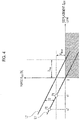
- Fig. 4 is a view showing a relationship between a displacement Z PZT of the piezoelectric element 11a1 and a thrust F PZT .
- a line L1 indicates the relationship of when a voltage is not applied
- a line L2 indicates the relationship of when a voltage is applied.
- a difference D between the line L1 and the line L2 in a vertical axis direction indicates an electric thrust generated inside the piezoelectric element 11a1 dependent on the applied voltage.
- the thrust generated by the piezoelectric element 11a1 includes the electric thrust and a mechanical thrust which is generated inside the piezoelectric element 11a1 dependent on a deformation amount of the piezoelectric element 11a1.
- a blocking force F Block indicates an external force required to set the extension of the piezoelectric element 11a1 to which the voltage is applied to zero.
- a no-load displacement Z Free indicates displacement when a voltage is applied to the piezoelectric element 11a1 in a no-load state.
- a point P1 corresponds to a state where the piezoelectric element 11a1 to which a voltage is not applied is compressed by x1 [ ⁇ m] and a preload having the same magnitude as that of the blocking force F Block is added.
- a point P2 corresponds to a state where the piezoelectric element 11a1 to which a voltage is not applied is compressed by x2 [ ⁇ m] and a preload which is larger than the blocking force F Block is added.
- a hatched region in Fig. 4 indicates an unusable region.
- the lamination ceramic type piezoelectric element has a structure in which electrodes and piezoceramics are alternately laminated and has a low pull allowable stress. Therefore, in a case where the piezoelectric element is used in the unusable region, there is a concern that the life of the element is shortened.
- the piezoelectric element 11a1 can easily generate a great thrust.
- the displacement is extremely small. Accordingly, the displacement is expanded using the buckling displacement expansion mechanism 11a.
- the buckling displacement expansion mechanism 11a can expand the displacement of the piezoelectric element 11a1 by 100 times or more and has characteristics capable of transmitting 70% or more of output energy.
- Fig. 5 is a schematic view showing the force acting on each component of the buckling displacement expansion mechanism 11a.
- Fig. 6 is a view showing a relationship between displacement (expansion output) y and the thrust F y of the output portion 11a3 in the buckling displacement expansion mechanism 11a.
- the thrust F y of the output portion 11a3 is represented by the following Expression (1).
- F y k PCS y 0 + 2 L k s k S + k PZT F V + F PL ⁇ k PCS y ⁇ 1 L 2 k S k PZT k S + k PZT y 3
- k PCS indicates mechanical compression stiffness of the spring preload adjustment mechanism 11c
- k PZT indicates mechanical compression stiffness of the piezoelectric element 11a1.
- k F indicates mechanical compression stiffness of the outer shell 11e
- k J indicates mechanical compression stiffness of the rolling joint.
- k S indicates total mechanical stiffness of the buckling displacement expansion mechanism 11a in the displacement direction of the piezoelectric element 11a1 and is dependent on the mechanical compression stiffness k F of the outer shell 11e and the mechanical compression stiffness k J of the rolling joint.
- y 0 indicates offset displacement of the spring preload adjustment mechanism 11c
- L indicates a distance between the rotation center of the rolling joint with respect to the fixation portion 11a2 and the rotation center of the rolling joint with respect to the output portion 11a3.
- F V indicates an electric thrust of the piezoelectric element 11a1
- F PL indicates a piezo preload generated by the piezo preload adjustment mechanism 11d
- F Z indicates a mechanical thrust generated in the piezoelectric element 11a1 dependent on the displacement amount of the piezoelectric element 11a1.
- a zero order term Fy0 of the displacement y is a component of the spring preload generated by the spring preload adjustment mechanism 11c in the displacement y direction.
- a first order term c 1 F V y of the displacement y is dependent on the spring preload adjusted by the spring preload adjustment mechanism 11c, the piezo preload F PL adjusted by the piezo preload adjustment mechanism 11d, and the electric thrust F V of the piezoelectric element 11a1.
- the piezo preload F PL and the spring preload are not present. This is because the piezo preload F PL and the spring preload set as in Expression (2) cancel each other out.
- the thrust F y of the output portion 11a3 is represented by the resultant force of a steady term F y0 having characteristics which are not dependent on the electric thrust F V of the piezoelectric element 11a1 and is not dependent on the displacement y, an input term c 1 F V y having characteristics which are dependent on the electric thrust F V of the piezoelectric element 11a1, and an elastic term c 3 y 3 having characteristics which are not dependent on the electric thrust F V of the piezoelectric element 11a1 but are dependent on the displacement y.
- Fig. 6 is a graph showing a relationship between the thrust F y and the displacement y of the output portion 11a3.
- a solid line in Fig. 6 indicates the relationship in a case where a voltage is not applied to the piezoelectric element 11a1
- a dotted line indicates the relationship in a case where a voltage is applied to the piezoelectric element 11a1.
- the thrust F y always becomes a positive value regardless of the magnitude of the displacement y and presence or absence of the applied voltage. That is, the output portion 11a3 always generates the thrust F y by which the output joint 11b is pressed against the periodic shape portion 20 of the motor output cam 2 regardless of the magnitude of the displacement y and presence or absence of the applied voltage.
- Fig. 7 is a view for explaining the movement of the follower roller 11b1 which comes into roll-contact with the periodic shape portion 20 of the motor output cam 2.
- a one-dot chain line in Fig. 7 indicates a locus drawn by the follower roller 11b1 of the output joint 11b attached to the output portion 11a3 of the buckling displacement expansion mechanism 11a which buckles in both directions of the +y direction and the -y direction when the capacitive actuator 1 moves in the +x direction.
- the expansion output of each of the six actuator units 11 is transmitted to the motor output cam 2 via the follower roller 11b1 of the output joint 11b and the periodic shape portion 20.
- the present embodiment is configured such that the locus drawn by the follower roller 11b1 when the capacitive actuator 1 linearly moves in the +x direction along the motor output cam 2 is a sine wave in a side view.
- a locus y(x) drawn by the follower roller 11b1 is represented by the following Expression (6)
- a differential value with respect to the relative position x of the locus y(x) which is an inclination of a tangent between the follower roller 11b1 and the periodic shape portion 20 at the relative position x is represented by the following Expression (7).
- y x y a sin 2 ⁇ ⁇ x
- dy x dx 2 ⁇ y a ⁇ cos 2 ⁇ ⁇ x
- y a indicates a half amplitude of the sine wave which is the locus drawn by the follower roller 11b1 and ⁇ indicates one wavelength.
- Expression (8) is represented by the following Expression (9) using Expression (5) and Expression (7).
- the steady term of the unit motor thrust F x (x) is represented by cos
- the input term is represented by Fv ⁇ cos ⁇ sin
- the elastic term is represented by -cos ⁇ sin 3 .
- Expression (9) is represented by the following Expression (10).
- coefficients A FC , A FX , and y Free are represented by the following Expression (11).
- the unit motor thrust F x (x) is represented by trigonometric function components with respect to three frequencies of a first harmonic (fundamental wave), a second harmonic, and a fourth harmonic.
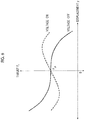
- Fig. 8 is a graph showing a transition with respect to the relative position x of the unit motor thrust F x (x) represented by Expression (10), and shows the transition in association with the sine wave W drawn by the follower roller 11b1.
- a transition T1 in Fig. 8 indicates a transition in a case where a voltage is not applied to the piezoelectric element 11a1
- a transition T2 indicates a transition in a case where a voltage is applied to the piezoelectric element 11a1.
- the transition of the unit motor thrust F x (x) has a point symmetrical relationship with respect to a zero point regardless of the presence or absence of the applied voltage.
- the motor output cam 2 integrates the plurality of unit motor thrust F x (x) having the above-described characteristics and the resultant force thereof is defined as motor thrust F M (x).
- the motor thrust F M (x) with respect to the relative position x is represented by the following Expression (12).
- ⁇ k indicates a relative phase angle of a position of a kth actuator unit 11 (the rotation center of the follower roller 11b1) with respect to a position of a first actuator unit 11 (the rotation center of the follower roller 11b1)
- F Vk indicates electric thrust F V of the piezoelectric element 11a1 in the kth actuator unit 11.
- the motor thrust F M (x) is represented by only the input term including the electric thrust F VK . That is, the steady term and the elastic term among the acting forces on the motor output cam 2 by the actuator units 11 cancel each other out between the actuator units 11. This is because other terms are eliminated by the theorem on trigonometric functions as shown in the following Expression (15).
- ⁇ k ⁇ 1 4 ⁇ 2 ⁇ p ⁇ k N
- k , m , N , p , q ⁇ positive integer 1 ⁇ k ⁇ N , N ⁇ 2 , p 2 q , q ⁇ even number , p ⁇ mN ⁇
- the motor thrust F M (x) of the capacitive actuator motor 100 which is disposed to have the phase which satisfies Expression (13) is represented by Expression (19).
- F W indicates an input amplitude which is the entire amplitude of the waveform (sine wave) of the applied voltage
- P com indicates an input phase which is a phase difference between the waveform (sine wave) of the applied voltage and the second harmonic of the sine wave which is the locus drawn by the follower roller 11b1.
- the motor thrust F M (x) of the capacitive actuator motor 100 disposed to have the phase which satisfies Expression (13) is proportional to the input amplitude F W and is proportional to cos (2P com ) which varies within a range of ⁇ 1 depending on the input phase P com .
- the input amplitude is used to control an absolute value of the motor thrust F M (x).
- the input phase does not suffer from the above-described limitation, it is possible to freely set the amplitude and polarity thereof.
- the unit motor thrust Fx(x) cancel each other out by the motor output cam 2 to obtain desired motor thrust F M (x).
- loss in energy inside the capacitive actuator 1 increases.
- the input phase is mainly used to control the polarity of the motor thrust F M (x)
- the input amplitude is mainly used to control the absolute value of the motor thrust F M (x).
- the motor thrust F M (x) of the capacitive actuator motor 100 which is disposed to have the phase which satisfies Expression (16) is represented by superimposing characteristics of a second term on the right side to characteristics of a first term on the right side.
- the characteristics of the first term on the right side are the same as the characteristics on the right side of Expression (19)
- the characteristics of the second term on the right side are characteristics dependent on a zero order term of the electric thrust F V of the actuator unit 11 represented by the coefficient A FC . Accordingly, it is not necessary to supply power in order to generate the motor thrust. Therefore, it can be used as a fall prevention function, for example, in applications which are driven while supporting the gravity.
- each of the N actuator units 11 always presses the output portion 11a3 to the surface of the periodic shape portion 20 of the motor output cam 2 regardless of the relative position x.
- the output portion 11a3 always presses the output portion 11a3 to the surface of the periodic shape portion 20 including a case where the output portion 11a3 is displaced in a direction which is away from the motor output cam 2. Accordingly, the capacitive actuator motor 100 can act all the energy which can be output by the piezoelectric elements 11a1 on the motor output cam 2.
- the capacitive actuator motor 100 can cancel out thrust components other than the thrust component (for example, the input term having characteristics dependent on the electric thrust F V ) of the piezoelectric element 11a1 caused by the input from the outside, between the actuator units 11. According, it is possible to realize high accuracy and high controllability by controlling only the applied voltage with respect to the piezoelectric element 11a1.
- the capacitive actuator motor 100 can cancel out thrust components other than the thrust component (for example, the input term having characteristics dependent on the electric thrust F V and the zero order term of the thrust F y of the actuator unit 11) of the piezoelectric element 11a1 caused by the input from the outside, between the actuator units 11. Accordingly, it is possible to realize not only high accuracy and high controllability but also position holding thrust when no power is supplied by controlling only the applied voltage with respect to the piezoelectric element 11a1.
- the offset force is adjusted by the preload adjustment spring 11a4 such that the thrust F y always has the same polarity. Accordingly, a user can always cause the follower roller 11b1 of the output joint 11b and the periodic shape portion 20 of the motor output cam 2 to come into contact with each other. Therefore, the capacitive actuator motor 100 can maintain a state in which all the output energy of the piezoelectric element 11a1 can be transmitted to the motor output cam 2, and it is possible to realize drive without backlash.
- the capacitive actuator motor 100 has a simple configuration using a motor output cam 2 having the periodic shape portion 20 on only the upper surface. Accordingly, it is possible to relatively easily realize reductions in size and weight of the capacitive actuator motor 100. In addition, pitching moment when the motor is driven is decreased by the reduction of size, and thus, the following effects can be realized. That is, operation accuracy is improved, operation noise is decreased, and loads with respect to vibrations in the motor guide 12 and the motor guide rail 21 are reduced.
- the above-described embodiment relates to the linear motor.
- the present invention may be applied to a rotary motor.
- the preload adjustment spring 11a4 is adopted as an example of the urging means.
- its own weight of the capacitive actuator 1 may be used as the urging means.
- the preload adjustment spring 11a4 presses the follower roller 11b1 of the output joint 11b to the periodic shape portion 20 of the motor output cam 2 via the output portion 11a3 of the buckling displacement expansion mechanism 11a.
- the preload adjustment spring 11a4 may pull the follower roller 11b1 in the direction of the periodic shape portion 20 so as to cause the follower roller 11b1 to come into contact with the periodic shape portion 20.
- the motor output cam 2 is disposed to extend in the horizontal direction.
- the motor output cam 2 may be disposed to extend in the vertical direction.
- the output direction of the output portion 11a3 is set to the direction (vertical direction) orthogonal to the extension direction (horizontal direction) of the motor output cam 2.
- the output direction of the output portion 11a3 is not necessarily the direction orthogonal to the extension direction of the motor output cam 2, and may be inclined with respect to the extension direction of the motor output cam 2.
Landscapes
- General Electrical Machinery Utilizing Piezoelectricity, Electrostriction Or Magnetostriction (AREA)
Abstract
Description
- The present invention relates to a capacitive actuator motor, a capacitive actuator, and a capacitive actuator unit.
- In the related art, a multi-pair buckling actuator which moves on an entirely linear rail including an upper surface having a periodic wave-shaped contour in a side view is known (for example, refer to PTL 1).
- The multi-pair buckling actuator includes a buckling mechanism which is a displacement expansion mechanism which expands extensions of a pair of piezoelectric elements disposed so as to face each other in a straight line in an output direction perpendicular to the extension direction and outputs the extension as displacement of an output portion. In addition, the buckling mechanism generates a thrust by pressing the output portion displaced in an output direction to a rail.
- [PTL 1] PCT Japanese Translation Patent Publication No.
2013-511254 - However, the thrust can be generated only in a case where the above-described multi-pair buckling actuator presses the output portion of the buckling mechanism to the rail. Accordingly, the thrust cannot be generated in a case where the output portion is away from the rail. Therefore, it is not possible to sufficiently use energy which can be output by the piezoelectric element.
- In view of the above, it is desirable to provide a capacitive actuator motor capable of more effectively using energy which can be output by an expandable element having capacitive properties.
- According to an embodiment of the present invention, there is provided a capacitive actuator motor, including: a capacitive actuator including a plurality of actuator units; and a motor output cam including a periodic shape portion, in which each of the plurality of actuator units includes a displacement expansion mechanism configured to convert an output of an expandable element having capacitive properties and urge an output transmission portion in a predetermined output direction and urging means configured to urge the output transmission portion with a certain characteristic in a direction in which the periodic shape portion and output transmission portion come into contact with each other.
- According to the above-described solution, it is possible to provide a capacitive actuator motor capable of more effectively using energy which can be output by an expandable element having capacitive properties.
-
-
Fig. 1A is a perspective view showing a configuration example of a capacitive actuator motor according to an embodiment of the present invention. -
Fig. 1B is a side view of the capacitive actuator motor. -
Fig. 1C is a top view of the capacitive actuator motor. -
Fig. 2A is a sectional view showing a configuration example of a main portion of the capacitive actuator motor. -
Fig. 2B is a sectional perspective view showing the configuration example of the main portion of the capacitive actuator motor. -
Fig. 3A is a perspective view of an actuator unit. -
Fig. 3B is a perspective view of the actuator unit in a state where a portion of an outer shell is cut out. -
Fig. 3C is a sectional view of the actuator unit. -
Fig. 4 is a view showing a relationship between displacement of a piezoelectric element and a thrust. -
Fig. 5 is a schematic view showing a force acting on each component of a buckling displacement expansion mechanism. -
Fig. 6 is a view showing a relationship between displacement (expansion output) and the thrust of an output portion in the buckling displacement expansion mechanism. -
Fig. 7 is a view for explaining a movement of a follower roller which comes into roll-contact with a periodic shape portion of a motor output cam. -
Fig. 8 is a graph showing a transition of a unit motor thrust. - Hereinafter, a preferred embodiment of the present invention will be described with reference to the drawings.
Figs. 1A to 1C are views showing a configuration example of acapacitive actuator motor 100 according to an embodiment of the present invention. Specifically,Fig. 1A is a perspective view of thecapacitive actuator motor 100,Fig. 1B is a side view of thecapacitive actuator motor 100, andFig. 1C is a top view of thecapacitive actuator motor 100. In addition,Figs. 2A and2B are views showing a configuration example of a main portion of thecapacitive actuator motor 100 inFigs. 1A to 1C . Specifically,Figs. 2A is a view of when a cross section shown by a one-dot chain line ofFig. 1B is viewed in a IIA direction, andFigs. 2B is a view of when a cross section shown by a one-dot chain line ofFig. 1C is viewed in a IIB direction. - The
capacitive actuator motor 100 mainly includes a capacitive actuator 1 and amotor output cam 2. - The capacitive actuator 1 is an actuator which generates a drive force using an expandable element having capacitive properties, and mainly includes a
motor frame 10,actuator units 11,motor guides 12, and expansion outputlinear guides 13. In the present invention, the expandable element having capacitive properties is a piezoelectric element. However, the expandable element may be a hydraulic cylinder, a pneumatic cylinder, or the like. - The
motor frame 10 is a functional element which bundles each of the plurality ofactuator units 11. In the present embodiment, themotor frame 10 is a frame-shaped member in a top view and each of sixactuator units 11 is fixed to the inner portion of the frame. - Each of the
actuator units 11 is a drive unit which configures the capacitive actuator 1. In the present embodiment, theactuator unit 11 mainly includes a bucklingdisplacement expansion mechanism 11a, anoutput joint 11b, springpreload adjustment mechanisms 11c, piezopreload adjustment mechanisms 11d, and anouter shell 11e. - The buckling
displacement expansion mechanism 11a is a mechanism which expands displacement of the expandable element using a buckling phenomenon. In the present embodiment, the bucklingdisplacement expansion mechanism 11a mainly includes a pair of piezoelectric elements 11a1, a pair of fixation portions 11a2, an output portion 11a3, and a preload adjustment spring 11a4. - Here, the
actuator unit 11 will be described in detail with reference toFigs. 3A to 3C . In addition,Fig. 3A is a perspective view of theactuator unit 11 andFig. 3B is a perspective view of theactuator unit 11 in a state where a portion of theouter shell 11e is cut out. Moreover,Fig. 3C is a sectional view showing the pair of piezoelectric elements 11a1, the pair of fixation portions 11a2, and the output portion 11a3. - One end of each of the pair of piezoelectric elements 11a1 is connected to the fixation portion 11a2 via a rolling joint and the other end thereof is connected to the output portion 11a3 via a rolling joint. In the present embodiment, the piezoelectric element 11a1 is configured of laminated ceramics. As shown in
Fig. 3C , the rolling joint means a connection via a rolling contact between an end spherical surface of a cap CP1 positioned on the left end of the left piezoelectric element 11a1 and an end spherical surface of the left fixation portion 11a2 and a connection via a rolling contact between an end spherical surface of a cap CP2 positioned on the right end of the left piezoelectric element 11a1 and the left end spherical surface of the output portion 11a3. Moreover, a circle C1 inFig. 3C indicates a circle including a contour of the end spherical surface of the left fixation portion 11a2, a circle C2 indicates a circle including contours of the end spherical surfaces of the caps CP1 and CP2, and a circle C3 indicates a contour of the left end spherical surface of the output portion 11a3. In addition, the right piezoelectric element 11a1 is also similar. - In a case where a voltage is applied to each of the pair of piezoelectric elements 11a1, the piezoelectric element 11a1 extends in a longitudinal direction (Y axis direction) to generate a buckling phenomenon and displaces the output portion 11a3 in a direction (Z axis direction) orthogonal to the longitudinal direction by displacement which is larger than the displacement of the extension. In this way, the buckling
displacement expansion mechanism 11a converts an output of each of the pair of piezoelectric elements 11a1, and urges and displaces the output portion 11a3 in a predetermined output direction. In addition, hereinafter, the displacement of the output portion 11a3 is referred to as an "expansion output". - Each of the pair of fixation portions 11a2 is a member which is fixed to the
motor frame 10. In the present embodiment, as shown inFig. 2A , the fixation portions 11a2 are fastened and fixed to themotor frame 10. - The output portion 11a3 is a function element which transmits the output of the buckling
displacement expansion mechanism 11a to the outside. In the present embodiment, in the output portion 11a3, the end portion on the +Z side is connected to the preload adjustment spring 11a4 and the end portion on the -Z side is connected to the output joint 11b. - The preload adjustment spring 11a4 is an example of urging means which urges the output portion 11a3 of the buckling
displacement expansion mechanism 11a with a certain characteristic. In the present embodiment, the preload adjustment spring 11a4 urges the output portion 11a3 in a direction in which themotor output cam 2 and the output joint 11b come into contact with each other and adjusts a displacement-thrust characteristic which is a relationship between the expansion output of the output portion 11a3 and a thrust caused by the expansion output. Specifically, the preload adjustment spring 11a4 is configured of a plate spring including a pair of curved portions which is curved to bulge in the -Z direction, a center portion of the preload adjustment spring 11a4 is fixed to the output portion 11a3, and both end portions thereof are connected to the pair of fixation portions 11a2 via the springpreload adjustment mechanism 11c. The preload adjustment spring 11a4 generates a force in the Z axis direction which offsets the thrust caused by the expansion output of the output portion 11a3. Hereinafter, the force generated by the preload adjustment spring 11a4 is referred to as an "offset force". - The output joint 11b is an example of an output transmission portion which transmits the output of the buckling
displacement expansion mechanism 11a to themotor output cam 2. In the present embodiment, the output joint 11b mainly includes a follower roller 11b1 and roller bearings 11b2, presses the follower roller 11b1 to aperiodic shape portion 20 of themotor output cam 2, and thus, transmits the expansion output of the output portion 11a3 to themotor output cam 2. In addition, the follower roller 11b1 is a member which comes into roll-contact with theperiodic shape portion 20 of themotor output cam 2. Moreover, each of the roller bearings 11b2 is a member which rotatably supports the follower roller 11b1 around a rotation axis extending in the Y axis direction. - The spring
preload adjustment mechanism 11c is a mechanism which adjusts an offset force by the preload adjustment spring 11a4. In the present embodiment, the springpreload adjustment mechanism 11c is configured of a wedge block. A user adjusts the positions of both end portions of the preload adjustment spring 11a4 in the Z axis direction, and thus, can adjust an offset force which is the force by which the center portion of the preload adjustment spring 11a4 presses the output portion 11a3 in the -Z direction. - The piezo
preload adjustment mechanism 11d is a mechanism which performs application and adjustment of a preload with respect to four rolling joints in the bucklingdisplacement expansion mechanism 11a. In the present embodiment, as shown inFig. 3C , the piezopreload adjustment mechanism 11d includes the cap CP1, a guide GD1, and a shim SH1. - The cap CP1 is a member which is attached to the left end of the left piezoelectric element 11a1 in order to configure the rolling joint between the left piezoelectric element 11a1 and the left fixation portion 11a2.
- The guide GD1 is a member which guides the cap CP1 to be detachably attached to the left end of the left piezoelectric element 11a1, and is fixed to the cap CP1. The cap CP1 and the shim SH1 are configured so as to transmit the thrust generated by the piezoelectric element 11a1 with high efficiency. Accordingly, preferably, the cap CP1 and the shim SH1 are formed of a material having high elasticity and strength such as a steel material or ceramics. The guide GD1 is configured so as to secure alignment of the caps CP1 and CP2 and the piezoelectric element 11a1 and protect an outer surface of the piezoelectric element 11a1. Therefore, preferably, the guide GD1 is formed of a material having lower elasticity than that of the piezoelectric element 11a1 or has a structure of low elasticity. Moreover, the cap CP1 and the guide GD1 may be integrally formed.
- The shim SH1 is a member which can be disposed between the cap CP1 and the left end of the left piezoelectric element 11a1 in the guide GD1 and is used to adjust a gap between the cap CP1 and the left end of the left piezoelectric element 11a1. The preloads with respect to the four rolling joints increase as the width of the shim SH1 in the Y axis direction increases.
- Moreover, the piezo
preload adjustment mechanism 11d may be disposed not only on the left end of the left piezoelectric element 11a1 but also on the right end of the left piezoelectric element 11a1. The right piezoelectric element 11a1 is also similar. - The
outer shell 11e is a functional element which fixes the distance between the pair of fixation portions 11a2. In the present embodiment, theouter shell 11e is a member which is formed to enclose the pair of piezoelectric elements 11a1, the pair of fixation portions 11a2, and the output portion 11a3, and prevents the distance between the pair of fixation portions 11a2 from increasing in a case where a buckling phenomenon is generated by the bucklingdisplacement expansion mechanism 11a. - The
motor guide 12 is a member which guides a linear motion of the capacitive actuator 1 along themotor output cam 2. In the present embodiment, themotor guide 12 is fixed to themotor frame 10 and engages with amotor guide rail 21 formed in themotor output cam 2. - The expansion output linear guide 13 (refer to
Fig. 2B ) is a functional element which guides the direction of the expansion output of the output portion 11a3 of the bucklingdisplacement expansion mechanism 11a. In the present embodiment, the expansion outputlinear guide 13 includes five guides which are disposed between sixactuator units 11 and two guides which are disposed between twoactuator units 11 of both ends and the motor frames 10. In addition, the expansion outputlinear guide 13 guides the linear motion of the output portion 11a3 in the Z axis direction such that the expansion output of the output portion 11a3 becomes the maximum. - Specifically, as shown in
Figs. 3A and3B , the expansion outputlinear guide 13 is not fixed to any member and is held in a state where the expansion outputlinear guide 13 is interposed between twooutput joints 11b or between the output joint 11b and themotor frame 10. In addition, the expansion outputlinear guide 13 includes aguide block 13a,ball retainers 13b, and guideballs 13c. Each of theguide balls 13c is held to be interposed between a ball receiving hole formed in theball retainer 13b attached to theguide block 13a and a groove 11b3 which is formed on the surface of the output joint 11b and is slidable along the groove 11b3. According to this configuration, the expansion outputlinear guide 13 can guide the linear motion of the output joint 11b in the Z axis direction. - The
motor output cam 2 is a functional element which integrates the expansion outputs of the plurality ofactuator units 11 in the capacitive actuator 1 into one continuous motor output and mainly includes theperiodic shape portion 20 and the motor guide rails 21. - The
periodic shape portion 20 is a functional element which comes into contact with the follower roller 11b1 configuring the output joint 11b of theactuator unit 11. In the present embodiment, as shown inFig. 1B , theperiodic shape portion 20 is a member which includes an upper surface having a periodic wave-shaped contour in a side view. Specifically, theperiodic shape portion 20 is configured such that a locus drawn by the rotation center of the follower roller 11b1 when the capacitive actuator 1 linearly moves along themotor output cam 2 is a sinusoid in a side view. That is, theperiodic shape portion 20 has a shape including a sinusoidal component. - Each of the
motor guide rails 21 is a functional element which guides the movement of the capacitive actuator 1 along themotor output cam 2. In the present embodiment, themotor guide rail 21 is configured to engage with themotor guide 12 of the capacitive actuator 1. Moreover, themotor guide 12 is operated to be guided by themotor guide rail 21. - Next, output characteristics of the piezoelectric element 11a1 will be described with reference to
Fig. 4. Fig. 4 is a view showing a relationship between a displacement ZPZT of the piezoelectric element 11a1 and a thrust FPZT. In addition, a line L1 indicates the relationship of when a voltage is not applied, and a line L2 indicates the relationship of when a voltage is applied. Moreover, a difference D between the line L1 and the line L2 in a vertical axis direction indicates an electric thrust generated inside the piezoelectric element 11a1 dependent on the applied voltage. Moreover, the thrust generated by the piezoelectric element 11a1 includes the electric thrust and a mechanical thrust which is generated inside the piezoelectric element 11a1 dependent on a deformation amount of the piezoelectric element 11a1. In addition, a blocking force FBlock indicates an external force required to set the extension of the piezoelectric element 11a1 to which the voltage is applied to zero. Moreover, a no-load displacement ZFree indicates displacement when a voltage is applied to the piezoelectric element 11a1 in a no-load state. In addition, a point P1 corresponds to a state where the piezoelectric element 11a1 to which a voltage is not applied is compressed by x1 [µm] and a preload having the same magnitude as that of the blocking force FBlock is added. Moreover, a point P2 corresponds to a state where the piezoelectric element 11a1 to which a voltage is not applied is compressed by x2 [µm] and a preload which is larger than the blocking force FBlock is added. Moreover, a hatched region inFig. 4 indicates an unusable region. The lamination ceramic type piezoelectric element has a structure in which electrodes and piezoceramics are alternately laminated and has a low pull allowable stress. Therefore, in a case where the piezoelectric element is used in the unusable region, there is a concern that the life of the element is shortened. - Moreover, the piezoelectric element 11a1 can easily generate a great thrust. However, the displacement is extremely small. Accordingly, the displacement is expanded using the buckling
displacement expansion mechanism 11a. In the present embodiment, the bucklingdisplacement expansion mechanism 11a can expand the displacement of the piezoelectric element 11a1 by 100 times or more and has characteristics capable of transmitting 70% or more of output energy. - Next, output characteristics of the buckling
displacement expansion mechanism 11a will be described with reference toFigs . 5 and6 .Fig. 5 is a schematic view showing the force acting on each component of the bucklingdisplacement expansion mechanism 11a. In addition,Fig. 6 is a view showing a relationship between displacement (expansion output) y and the thrust Fy of the output portion 11a3 in the bucklingdisplacement expansion mechanism 11a. - The thrust Fy of the output portion 11a3 is represented by the following Expression (1).
[Expression 1]
- In addition, in Expression (1) or
Fig. 5 , kPCS indicates mechanical compression stiffness of the springpreload adjustment mechanism 11c, and kPZT indicates mechanical compression stiffness of the piezoelectric element 11a1. Moreover, kF indicates mechanical compression stiffness of theouter shell 11e, and kJ indicates mechanical compression stiffness of the rolling joint. In addition, kS indicates total mechanical stiffness of the bucklingdisplacement expansion mechanism 11a in the displacement direction of the piezoelectric element 11a1 and is dependent on the mechanical compression stiffness kF of theouter shell 11e and the mechanical compression stiffness kJ of the rolling joint. Moreover, y0 indicates offset displacement of the springpreload adjustment mechanism 11c, and L indicates a distance between the rotation center of the rolling joint with respect to the fixation portion 11a2 and the rotation center of the rolling joint with respect to the output portion 11a3. In addition, FV indicates an electric thrust of the piezoelectric element 11a1, FPL indicates a piezo preload generated by the piezopreload adjustment mechanism 11d, and FZ indicates a mechanical thrust generated in the piezoelectric element 11a1 dependent on the displacement amount of the piezoelectric element 11a1. - If various mechanical stiffness is set such that the piezo preload FPL becomes a value represented by the following Expression (2), the thrust Fy is represented by the following Expression (3).
[Expression 2]
[Expression 3]
- Moreover, if a zero order term Fy0 of the displacement y, a coefficient C1 with respect to the FV of the first order term of the displacement y, and a third order coefficient C3 of the displacement y are defined as the following Expression (4), the thrust Fy is represented by the following Expression (5).
[Expression 4]
[Expression 5]
- Moreover, a zero order term Fy0 of the displacement y is a component of the spring preload generated by the spring
preload adjustment mechanism 11c in the displacement y direction. In addition, a first order term c1FVy of the displacement y is dependent on the spring preload adjusted by the springpreload adjustment mechanism 11c, the piezo preload FPL adjusted by the piezopreload adjustment mechanism 11d, and the electric thrust FV of the piezoelectric element 11a1. Moreover, in Expression (5), the piezo preload FPL and the spring preload are not present. This is because the piezo preload FPL and the spring preload set as in Expression (2) cancel each other out. - In this way, the thrust Fy of the output portion 11a3 is represented by the resultant force of a steady term Fy0 having characteristics which are not dependent on the electric thrust FV of the piezoelectric element 11a1 and is not dependent on the displacement y, an input term c1FVy having characteristics which are dependent on the electric thrust FV of the piezoelectric element 11a1, and an elastic term c3y3 having characteristics which are not dependent on the electric thrust FV of the piezoelectric element 11a1 but are dependent on the displacement y.
-
Fig. 6 is a graph showing a relationship between the thrust Fy and the displacement y of the output portion 11a3. In addition, a solid line inFig. 6 indicates the relationship in a case where a voltage is not applied to the piezoelectric element 11a1, and a dotted line indicates the relationship in a case where a voltage is applied to the piezoelectric element 11a1. - As shown in
Fig. 6 , the thrust Fy always becomes a positive value regardless of the magnitude of the displacement y and presence or absence of the applied voltage. That is, the output portion 11a3 always generates the thrust Fy by which the output joint 11b is pressed against theperiodic shape portion 20 of themotor output cam 2 regardless of the magnitude of the displacement y and presence or absence of the applied voltage. - Next, unit motor thrust Fx(x) which is transmitted to the
motor output cam 2 by each of the plurality of bucklingdisplacement expansion mechanism 11a will be described with reference toFig. 7. Fig. 7 is a view for explaining the movement of the follower roller 11b1 which comes into roll-contact with theperiodic shape portion 20 of themotor output cam 2. - Specifically, a one-dot chain line in
Fig. 7 indicates a locus drawn by the follower roller 11b1 of the output joint 11b attached to the output portion 11a3 of the bucklingdisplacement expansion mechanism 11a which buckles in both directions of the +y direction and the -y direction when the capacitive actuator 1 moves in the +x direction. - In the present embodiment, the expansion output of each of the six
actuator units 11 is transmitted to themotor output cam 2 via the follower roller 11b1 of the output joint 11b and theperiodic shape portion 20. In addition, the present embodiment is configured such that the locus drawn by the follower roller 11b1 when the capacitive actuator 1 linearly moves in the +x direction along themotor output cam 2 is a sine wave in a side view. - If displacement of the follower roller 11b1 in the expansion output direction is defined as y and a relative position of the capacitive actuator 1 with respect to the
motor output cam 2 is defined as x, a locus y(x) drawn by the follower roller 11b1 is represented by the following Expression (6), and a differential value with respect to the relative position x of the locus y(x) which is an inclination of a tangent between the follower roller 11b1 and theperiodic shape portion 20 at the relative position x is represented by the following Expression (7).
[Expression 6]
[Expression 7]
- In addition, ya indicates a half amplitude of the sine wave which is the locus drawn by the follower roller 11b1 and λ indicates one wavelength.
- In addition, as the following Expression (8), the unit motor thrust Fx(x) which is transmitted to the
motor output cam 2 by each of the sixactuator units 11 is represented by a product of the thrust Fy(x) of the output portion 11a3 and the inclination dy(x)/dx of the tangent at the relative position x.
[Expression 8]
- In addition, Expression (8) is represented by the following Expression (9) using Expression (5) and Expression (7).
[Expression 9]
- That is, the steady term of the unit motor thrust Fx(x) is represented by cos, the input term is represented by Fv·cos·sin, and the elastic term is represented by -cos·sin3.
- Moreover, if a half amplitude ya of the sine wave drawn by the follower roller 11b1 is defined as a value yFree, Expression (9) is represented by the following Expression (10). In addition, coefficients AFC, AFX, and yFree are represented by the following Expression (11). In this case, the unit motor thrust Fx(x) is represented by trigonometric function components with respect to three frequencies of a first harmonic (fundamental wave), a second harmonic, and a fourth harmonic.
[Expression 10]

-
Fig. 8 is a graph showing a transition with respect to the relative position x of the unit motor thrust Fx(x) represented by Expression (10), and shows the transition in association with the sine wave W drawn by the follower roller 11b1. In addition, a transition T1 inFig. 8 indicates a transition in a case where a voltage is not applied to the piezoelectric element 11a1, and a transition T2 indicates a transition in a case where a voltage is applied to the piezoelectric element 11a1. - As shown in
Fig. 8 , the transition of the unit motor thrust Fx(x) has a point symmetrical relationship with respect to a zero point regardless of the presence or absence of the applied voltage. - The
motor output cam 2 integrates the plurality of unit motor thrust Fx(x) having the above-described characteristics and the resultant force thereof is defined as motor thrust FM(x). In addition, in a case whereN actuator units 11 are disposed with respect to themotor output cam 2 so that equiphase intervals are obtained at a length equal to or more than one wavelength of the sine wave drawn by the follower roller 11b1, that is, one or more periods of theperiodic shape portion 20 are equally divided, the motor thrust FM(x) with respect to the relative position x is represented by the following Expression (12).
[Expression 12]
- In addition, φk indicates a relative phase angle of a position of a kth actuator unit 11 (the rotation center of the follower roller 11b1) with respect to a position of a first actuator unit 11 (the rotation center of the follower roller 11b1), and FVk indicates electric thrust FV of the piezoelectric element 11a1 in the
kth actuator unit 11. - In addition, in a case of a phase disposition in which the N actuator units 11 (the rotation center of the follower roller 11b1) satisfy the following Expression (13), as the following Expression (14), the motor thrust FM(x) is represented by only the input term including the electric thrust FVK. That is, the steady term and the elastic term among the acting forces on the
motor output cam 2 by theactuator units 11 cancel each other out between theactuator units 11. This is because other terms are eliminated by the theorem on trigonometric functions as shown in the following Expression (15).
[Expression 13]
[Expression 14]
[Expression 15]
- In addition, in a case of a phase disposition in which the N actuator units 11 (the rotation center of the follower roller 11b1) satisfy the following Expression (16), as the following Expression (17), the motor thrust FM(x) is represented by only the steady term and the input term. That is, the elastic terms among the acting forces on the
motor output cam 2 by theactuator units 11 cancel each other out between theactuator units 11.
[Expression 16]
[Expression 17]
- Moreover, in a case where the applied voltage is adjusted such that the electric thrust FVk of the piezoelectric element 11a1 of each of the
N actuator units 11 becomes the sine wave shown in the following Expression (18), the motor thrust FM(x) of thecapacitive actuator motor 100 which is disposed to have the phase which satisfies Expression (13) is represented by Expression (19). In addition, FW indicates an input amplitude which is the entire amplitude of the waveform (sine wave) of the applied voltage, and Pcom indicates an input phase which is a phase difference between the waveform (sine wave) of the applied voltage and the second harmonic of the sine wave which is the locus drawn by the follower roller 11b1.
[Expression 18]
[Expression 19]
- As shown in Expression (19), the motor thrust FM(x) of the
capacitive actuator motor 100 disposed to have the phase which satisfies Expression (13) is proportional to the input amplitude FW and is proportional to cos (2Pcom) which varies within a range of ±1 depending on the input phase Pcom. Moreover, considering polarization characteristics of the piezoelectric element 11a1, it is not preferable to give a negative value to the input amplitude. Accordingly, preferably, the input amplitude is used to control an absolute value of the motor thrust FM(x). - In addition, since the input phase does not suffer from the above-described limitation, it is possible to freely set the amplitude and polarity thereof. In addition, when the input amplitude increases in a case where small motor thrust FM(x) is obtained, the unit motor thrust Fx(x) cancel each other out by the
motor output cam 2 to obtain desired motor thrust FM(x). However, in this case, loss in energy inside the capacitive actuator 1 increases. Accordingly, preferably, the input phase is mainly used to control the polarity of the motor thrust FM(x), and the input amplitude is mainly used to control the absolute value of the motor thrust FM(x). - Moreover, in a case where the applied voltage is adjusted such that the electric thrust FVk of the piezoelectric element 11a1 of each of the
N actuator units 11 becomes the sine wave shown in Expression (18), the motor thrust FM(x) of thecapacitive actuator motor 100 which is disposed to have the phase which satisfies Expression (13) is represented by Expression (20).
[Expression 20]
- As shown in Expression (20), the motor thrust FM(x) of the
capacitive actuator motor 100 which is disposed to have the phase which satisfies Expression (16) is represented by superimposing characteristics of a second term on the right side to characteristics of a first term on the right side. In addition, the characteristics of the first term on the right side are the same as the characteristics on the right side of Expression (19), and the characteristics of the second term on the right side are characteristics dependent on a zero order term of the electric thrust FV of theactuator unit 11 represented by the coefficient AFC. Accordingly, it is not necessary to supply power in order to generate the motor thrust. Therefore, it can be used as a fall prevention function, for example, in applications which are driven while supporting the gravity. - Moreover, as described above, in any case of the
capacitive actuator motor 100 disposed to have the phase which satisfies Expression (13) or Expression (16), each of theN actuator units 11 always presses the output portion 11a3 to the surface of theperiodic shape portion 20 of themotor output cam 2 regardless of the relative position x. Specifically, the output portion 11a3 always presses the output portion 11a3 to the surface of theperiodic shape portion 20 including a case where the output portion 11a3 is displaced in a direction which is away from themotor output cam 2. Accordingly, thecapacitive actuator motor 100 can act all the energy which can be output by the piezoelectric elements 11a1 on themotor output cam 2. - In addition, according to the configuration in which the plurality of
actuator units 11 are appropriately disposed considering the phase of theperiodic shape portion 20 as shown in Expression (13), thecapacitive actuator motor 100 can cancel out thrust components other than the thrust component (for example, the input term having characteristics dependent on the electric thrust FV) of the piezoelectric element 11a1 caused by the input from the outside, between theactuator units 11. According, it is possible to realize high accuracy and high controllability by controlling only the applied voltage with respect to the piezoelectric element 11a1. - In addition, according to the configuration in which the plurality of
actuator units 11 are appropriately disposed considering the phase of theperiodic shape portion 20 as shown in Expression (16), thecapacitive actuator motor 100 can cancel out thrust components other than the thrust component (for example, the input term having characteristics dependent on the electric thrust FV and the zero order term of the thrust Fy of the actuator unit 11) of the piezoelectric element 11a1 caused by the input from the outside, between theactuator units 11. Accordingly, it is possible to realize not only high accuracy and high controllability but also position holding thrust when no power is supplied by controlling only the applied voltage with respect to the piezoelectric element 11a1. - Moreover, the offset force is adjusted by the preload adjustment spring 11a4 such that the thrust Fy always has the same polarity. Accordingly, a user can always cause the follower roller 11b1 of the output joint 11b and the
periodic shape portion 20 of themotor output cam 2 to come into contact with each other. Therefore, thecapacitive actuator motor 100 can maintain a state in which all the output energy of the piezoelectric element 11a1 can be transmitted to themotor output cam 2, and it is possible to realize drive without backlash. - Moreover, the
capacitive actuator motor 100 has a simple configuration using amotor output cam 2 having theperiodic shape portion 20 on only the upper surface. Accordingly, it is possible to relatively easily realize reductions in size and weight of thecapacitive actuator motor 100. In addition, pitching moment when the motor is driven is decreased by the reduction of size, and thus, the following effects can be realized. That is, operation accuracy is improved, operation noise is decreased, and loads with respect to vibrations in themotor guide 12 and themotor guide rail 21 are reduced. - Hereinbefore, the embodiment of the present invention is described. However, the present invention is not limited to a specific embodiment and various changes and modifications can be applied to the present invention within the scope of the gist of the present invention described in claims.
- For example, the above-described embodiment relates to the linear motor. However, the present invention may be applied to a rotary motor.
- Moreover, in the above-described embodiment, the preload adjustment spring 11a4 is adopted as an example of the urging means. However, its own weight of the capacitive actuator 1 may be used as the urging means.
- In addition, in the above-described embodiment, the preload adjustment spring 11a4 presses the follower roller 11b1 of the output joint 11b to the
periodic shape portion 20 of themotor output cam 2 via the output portion 11a3 of the bucklingdisplacement expansion mechanism 11a. However, the preload adjustment spring 11a4 may pull the follower roller 11b1 in the direction of theperiodic shape portion 20 so as to cause the follower roller 11b1 to come into contact with theperiodic shape portion 20. - Moreover, in the above-described embodiment, the
motor output cam 2 is disposed to extend in the horizontal direction. However, themotor output cam 2 may be disposed to extend in the vertical direction. - In addition, in the above-described embodiment, the output direction of the output portion 11a3 is set to the direction (vertical direction) orthogonal to the extension direction (horizontal direction) of the
motor output cam 2. However, the output direction of the output portion 11a3 is not necessarily the direction orthogonal to the extension direction of themotor output cam 2, and may be inclined with respect to the extension direction of themotor output cam 2. - In addition, priority is claimed to Japanese Patent Application No.
2015-056868, filed March 19, 2015 -
- 1: capacitive actuator
- 2: motor output cam
- 10: motor frame
- 11: actuator unit
- 11a: buckling displacement expansion mechanism
- 11a1: piezoelectric element
- 11a2: fixation portion
- 11a3: output portion
- 11a4: preload adjustment spring
- 11b: output joint
- 11b1: follower roller
- 11b2: roller bearing
- 11b3: groove
- 11c: spring preload adjustment mechanism
- 11d: piezo preload adjustment mechanism
- 11e: outer shell
- 12: motor guide
- 13: expansion output linear guide
- 13a: guide block
- 13b: ball retainer
- 13c: guide ball
- 20: periodic shape portion
- 21: motor guide rail
- 100: capacitive actuator motor
- CP1, CP2: cap
- GD1: guide
- SH1: shim
Claims (10)
- A capacitive actuator motor, comprising:a capacitive actuator including a plurality of actuator units; anda motor output cam including a periodic shape portion,wherein each of the plurality of actuator units includes a displacement expansion mechanism configured to convert an output of an expandable element having capacitive properties and urge an output transmission portion in a predetermined output direction and urging means configured to urge the output transmission portion with a certain characteristic in a direction in which the periodic shape portion and output transmission portion come into contact with each other.
- The capacitive actuator motor according to claim 1,
wherein each of the plurality of actuator units generates a unit motor thrust by pressing or pulling the output transmission portion in the direction of the motor output cam, and
wherein each of the plurality of actuator units is disposed at a phase interval with respect to the periodic shape portion such that, in a motor thrust which is a resultant force of unit motor thrusts generated by each of the plurality of actuator units, thrust components other than a thrust component generated by an input of the expandable element from the outside cancel each other out between the plurality of actuator units. - The capacitive actuator motor according to claim 1,
wherein each of the plurality of actuator units generates a unit motor thrust by pressing or pulling the output transmission portion in the direction of the motor output cam, and
wherein each of the plurality of actuator units is disposed at a phase interval with respect to the periodic shape portion such that, in a motor thrust which is a resultant force of unit motor thrusts generated by each of the plurality of actuator units, a thrust component generated by an input of the expandable element from the outside and thrust components other than a thrust component generated by the urging means cancel each other out between the plurality of actuator units. - The capacitive actuator motor according to claim 2,
wherein a disposition of each of the plurality of actuator units at the phase interval with respect to the periodic shape portion includes a disposition which equally divides one or more periods of the periodic shape portion. - The capacitive actuator motor according to claim 1,
wherein the expandable element is a piezoelectric element, and
wherein the displacement expansion mechanism is a buckling displacement expansion mechanism. - The capacitive actuator motor according to claim 1,
wherein the displacement expansion mechanism is a buckling displacement expansion mechanism. - The capacitive actuator motor according to claim 1,
wherein the output transmission portion includes a roller, and
wherein the periodic shape portion has a shape which includes a sinusoidal component. - An actuator unit in the capacitive actuator motor according to claim 1.
- A capacitive actuator in the capacitive actuator motor according to claim 1.
- The capacitive actuator motor according to claim 3,
wherein a disposition of each of the plurality of actuator units at the phase interval with respect to the periodic shape portion includes a disposition through which one or more periods of the periodic shape portion are equally divided.
Applications Claiming Priority (2)
| Application Number | Priority Date | Filing Date | Title |
|---|---|---|---|
| JP2015056868A JP6453123B2 (en) | 2015-03-19 | 2015-03-19 | Actuator |
| PCT/JP2015/085111 WO2016147507A1 (en) | 2015-03-19 | 2015-12-15 | Capacitive actuator motor, capacitive actuator, and capacitive actuator unit |
Publications (3)
| Publication Number | Publication Date |
|---|---|
| EP3273591A1 true EP3273591A1 (en) | 2018-01-24 |
| EP3273591A4 EP3273591A4 (en) | 2018-12-05 |
| EP3273591B1 EP3273591B1 (en) | 2023-04-19 |
Family
ID=56920013
Family Applications (1)
| Application Number | Title | Priority Date | Filing Date |
|---|---|---|---|
| EP15885599.9A Active EP3273591B1 (en) | 2015-03-19 | 2015-12-15 | Capacitive actuator motor |
Country Status (4)
| Country | Link |
|---|---|
| US (1) | US10924038B2 (en) |
| EP (1) | EP3273591B1 (en) |
| JP (1) | JP6453123B2 (en) |
| WO (1) | WO2016147507A1 (en) |
Families Citing this family (2)
| Publication number | Priority date | Publication date | Assignee | Title |
|---|---|---|---|---|
| US20160336878A1 (en) * | 2015-05-11 | 2016-11-17 | Massachusetts Institute Of Technology | Poly-actuator |
| JP6961505B2 (en) * | 2017-03-13 | 2021-11-05 | 住友重機械工業株式会社 | Displacement expansion mechanism and valve drive device |
Family Cites Families (7)
| Publication number | Priority date | Publication date | Assignee | Title |
|---|---|---|---|---|
| GB0721433D0 (en) * | 2007-11-01 | 2007-12-12 | Qinetiq Ltd | Temperature compensating flextensional transducer |
| GB2466745B (en) * | 2007-11-01 | 2012-03-14 | Qinetiq Ltd | Nested flextensional transducers |
| EP2499734A4 (en) | 2009-11-10 | 2014-05-07 | Massachusetts Inst Technology | FLASHING ACTUATOR WITH PHASE GROUPING |
| JP2012121130A (en) * | 2010-11-18 | 2012-06-28 | Nagatsu Precision Mold Co Ltd | Polishing equipment |
| JP6328905B2 (en) * | 2012-10-16 | 2018-05-23 | マサチューセッツ インスティテュート オブ テクノロジー | Buckling actuator |
| JP6333024B2 (en) * | 2013-04-04 | 2018-05-30 | マサチューセッツ インスティテュート オブ テクノロジー | Motor, control system and control method |
| US20160336878A1 (en) * | 2015-05-11 | 2016-11-17 | Massachusetts Institute Of Technology | Poly-actuator |
-
2015
- 2015-03-19 JP JP2015056868A patent/JP6453123B2/en not_active Expired - Fee Related
- 2015-12-15 WO PCT/JP2015/085111 patent/WO2016147507A1/en not_active Ceased
- 2015-12-15 EP EP15885599.9A patent/EP3273591B1/en active Active
-
2017
- 2017-09-12 US US15/702,357 patent/US10924038B2/en not_active Expired - Fee Related
Also Published As
| Publication number | Publication date |
|---|---|
| JP2016178782A (en) | 2016-10-06 |
| WO2016147507A1 (en) | 2016-09-22 |
| JP6453123B2 (en) | 2019-01-16 |
| EP3273591A4 (en) | 2018-12-05 |
| EP3273591B1 (en) | 2023-04-19 |
| US20180006585A1 (en) | 2018-01-04 |
| US10924038B2 (en) | 2021-02-16 |
Similar Documents
| Publication | Publication Date | Title |
|---|---|---|
| US8760036B2 (en) | Vibration wave driving apparatus | |
| JP4802313B2 (en) | Holding device for piezoelectric vibrator | |
| US11407105B2 (en) | Variable stiffness actuator with electrically modulated stiffness | |
| Chen et al. | A variable positive-negative stiffness joint with low frequency vibration isolation performance | |
| EP3121472A1 (en) | Planar flexure members and actuators using them | |
| EP3273591B1 (en) | Capacitive actuator motor | |
| Knox et al. | A unidirectional series-elastic actuator design using a spiral torsion spring | |
| JP6856519B2 (en) | Battery module | |
| JP6328905B2 (en) | Buckling actuator | |
| US20160336878A1 (en) | Poly-actuator | |
| US8736148B2 (en) | Multiple degree of freedom actuator and method | |
| US20150167801A1 (en) | Motor with linear actuators | |
| EP3924637A1 (en) | Nonlinear spring mechanism for actuation systems and its design method | |
| JP6961505B2 (en) | Displacement expansion mechanism and valve drive device | |
| JP2020198687A (en) | Vibration type actuator, device, multiaxial stage unit, and multi-joint robot | |
| JP5137406B2 (en) | Vibration type driving device | |
| Thanaki et al. | Synthesizing bidirectional constant torque compliant mechanisms using precompressed beams | |
| US11190112B2 (en) | Vibration wave motor and drive device using the same | |
| JP7346450B2 (en) | Displacement magnification mechanism and actuator | |
| JP7557456B2 (en) | Bellows mounting structure | |
| JP2017051080A (en) | Displacement magnification mechanism | |
| RU2402698C2 (en) | Connecting device deformed in one direction | |
| JP2020102920A (en) | Displacement magnifying mechanism, actuator, and method of adjusting displacement magnifying mechanism | |
| EP4020787A1 (en) | Band-type brake device, robot joint, and collaborative robot | |
| JP6427446B2 (en) | Actuator |
Legal Events
| Date | Code | Title | Description |
|---|---|---|---|
| STAA | Information on the status of an ep patent application or granted ep patent |
Free format text: STATUS: THE INTERNATIONAL PUBLICATION HAS BEEN MADE |
|
| PUAI | Public reference made under article 153(3) epc to a published international application that has entered the european phase |
Free format text: ORIGINAL CODE: 0009012 |
|
| STAA | Information on the status of an ep patent application or granted ep patent |
Free format text: STATUS: REQUEST FOR EXAMINATION WAS MADE |
|
| 17P | Request for examination filed |
Effective date: 20170911 |
|
| AK | Designated contracting states |
Kind code of ref document: A1 Designated state(s): AL AT BE BG CH CY CZ DE DK EE ES FI FR GB GR HR HU IE IS IT LI LT LU LV MC MK MT NL NO PL PT RO RS SE SI SK SM TR |
|
| AX | Request for extension of the european patent |
Extension state: BA ME |
|
| DAV | Request for validation of the european patent (deleted) | ||
| DAX | Request for extension of the european patent (deleted) | ||
| STAA | Information on the status of an ep patent application or granted ep patent |
Free format text: STATUS: EXAMINATION IS IN PROGRESS |
|
| A4 | Supplementary search report drawn up and despatched |
Effective date: 20181030 |
|
| RIC1 | Information provided on ipc code assigned before grant |
Ipc: H02N 1/00 20060101AFI20181024BHEP |
|
| 17Q | First examination report despatched |
Effective date: 20181116 |
|
| REG | Reference to a national code |
Ref country code: DE Ref legal event code: R079 Ref document number: 602015083256 Country of ref document: DE Free format text: PREVIOUS MAIN CLASS: H02N0001000000 Ipc: H02N0002020000 |
|
| GRAP | Despatch of communication of intention to grant a patent |
Free format text: ORIGINAL CODE: EPIDOSNIGR1 |
|
| STAA | Information on the status of an ep patent application or granted ep patent |
Free format text: STATUS: GRANT OF PATENT IS INTENDED |
|
| RIC1 | Information provided on ipc code assigned before grant |
Ipc: H02N 1/00 20060101ALI20221114BHEP Ipc: H02N 2/04 20060101ALI20221114BHEP Ipc: H02N 2/02 20060101AFI20221114BHEP |
|
| INTG | Intention to grant announced |
Effective date: 20221201 |
|
| GRAS | Grant fee paid |
Free format text: ORIGINAL CODE: EPIDOSNIGR3 |
|
| GRAA | (expected) grant |
Free format text: ORIGINAL CODE: 0009210 |
|
| STAA | Information on the status of an ep patent application or granted ep patent |
Free format text: STATUS: THE PATENT HAS BEEN GRANTED |
|
| AK | Designated contracting states |
Kind code of ref document: B1 Designated state(s): AL AT BE BG CH CY CZ DE DK EE ES FI FR GB GR HR HU IE IS IT LI LT LU LV MC MK MT NL NO PL PT RO RS SE SI SK SM TR |
|
| REG | Reference to a national code |
Ref country code: GB Ref legal event code: FG4D |
|
| REG | Reference to a national code |
Ref country code: DE Ref legal event code: R096 Ref document number: 602015083256 Country of ref document: DE |
|
| REG | Reference to a national code |
Ref country code: CH Ref legal event code: EP |
|
| REG | Reference to a national code |
Ref country code: IE Ref legal event code: FG4D |
|
| REG | Reference to a national code |
Ref country code: AT Ref legal event code: REF Ref document number: 1561945 Country of ref document: AT Kind code of ref document: T Effective date: 20230515 |
|
| REG | Reference to a national code |
Ref country code: LT Ref legal event code: MG9D |
|
| REG | Reference to a national code |
Ref country code: NL Ref legal event code: MP Effective date: 20230419 |
|
| REG | Reference to a national code |
Ref country code: AT Ref legal event code: MK05 Ref document number: 1561945 Country of ref document: AT Kind code of ref document: T Effective date: 20230419 |
|
| PG25 | Lapsed in a contracting state [announced via postgrant information from national office to epo] |
Ref country code: NL Free format text: LAPSE BECAUSE OF FAILURE TO SUBMIT A TRANSLATION OF THE DESCRIPTION OR TO PAY THE FEE WITHIN THE PRESCRIBED TIME-LIMIT Effective date: 20230419 |
|
| PG25 | Lapsed in a contracting state [announced via postgrant information from national office to epo] |
Ref country code: SE Free format text: LAPSE BECAUSE OF FAILURE TO SUBMIT A TRANSLATION OF THE DESCRIPTION OR TO PAY THE FEE WITHIN THE PRESCRIBED TIME-LIMIT Effective date: 20230419 Ref country code: PT Free format text: LAPSE BECAUSE OF FAILURE TO SUBMIT A TRANSLATION OF THE DESCRIPTION OR TO PAY THE FEE WITHIN THE PRESCRIBED TIME-LIMIT Effective date: 20230821 Ref country code: NO Free format text: LAPSE BECAUSE OF FAILURE TO SUBMIT A TRANSLATION OF THE DESCRIPTION OR TO PAY THE FEE WITHIN THE PRESCRIBED TIME-LIMIT Effective date: 20230719 Ref country code: ES Free format text: LAPSE BECAUSE OF FAILURE TO SUBMIT A TRANSLATION OF THE DESCRIPTION OR TO PAY THE FEE WITHIN THE PRESCRIBED TIME-LIMIT Effective date: 20230419 Ref country code: AT Free format text: LAPSE BECAUSE OF FAILURE TO SUBMIT A TRANSLATION OF THE DESCRIPTION OR TO PAY THE FEE WITHIN THE PRESCRIBED TIME-LIMIT Effective date: 20230419 |
|
| PG25 | Lapsed in a contracting state [announced via postgrant information from national office to epo] |
Ref country code: RS Free format text: LAPSE BECAUSE OF FAILURE TO SUBMIT A TRANSLATION OF THE DESCRIPTION OR TO PAY THE FEE WITHIN THE PRESCRIBED TIME-LIMIT Effective date: 20230419 Ref country code: PL Free format text: LAPSE BECAUSE OF FAILURE TO SUBMIT A TRANSLATION OF THE DESCRIPTION OR TO PAY THE FEE WITHIN THE PRESCRIBED TIME-LIMIT Effective date: 20230419 Ref country code: LV Free format text: LAPSE BECAUSE OF FAILURE TO SUBMIT A TRANSLATION OF THE DESCRIPTION OR TO PAY THE FEE WITHIN THE PRESCRIBED TIME-LIMIT Effective date: 20230419 Ref country code: LT Free format text: LAPSE BECAUSE OF FAILURE TO SUBMIT A TRANSLATION OF THE DESCRIPTION OR TO PAY THE FEE WITHIN THE PRESCRIBED TIME-LIMIT Effective date: 20230419 Ref country code: IS Free format text: LAPSE BECAUSE OF FAILURE TO SUBMIT A TRANSLATION OF THE DESCRIPTION OR TO PAY THE FEE WITHIN THE PRESCRIBED TIME-LIMIT Effective date: 20230819 Ref country code: HR Free format text: LAPSE BECAUSE OF FAILURE TO SUBMIT A TRANSLATION OF THE DESCRIPTION OR TO PAY THE FEE WITHIN THE PRESCRIBED TIME-LIMIT Effective date: 20230419 Ref country code: GR Free format text: LAPSE BECAUSE OF FAILURE TO SUBMIT A TRANSLATION OF THE DESCRIPTION OR TO PAY THE FEE WITHIN THE PRESCRIBED TIME-LIMIT Effective date: 20230720 Ref country code: AL Free format text: LAPSE BECAUSE OF FAILURE TO SUBMIT A TRANSLATION OF THE DESCRIPTION OR TO PAY THE FEE WITHIN THE PRESCRIBED TIME-LIMIT Effective date: 20230419 |
|
| PG25 | Lapsed in a contracting state [announced via postgrant information from national office to epo] |
Ref country code: FI Free format text: LAPSE BECAUSE OF FAILURE TO SUBMIT A TRANSLATION OF THE DESCRIPTION OR TO PAY THE FEE WITHIN THE PRESCRIBED TIME-LIMIT Effective date: 20230419 |
|
| PG25 | Lapsed in a contracting state [announced via postgrant information from national office to epo] |
Ref country code: SK Free format text: LAPSE BECAUSE OF FAILURE TO SUBMIT A TRANSLATION OF THE DESCRIPTION OR TO PAY THE FEE WITHIN THE PRESCRIBED TIME-LIMIT Effective date: 20230419 |
|
| REG | Reference to a national code |
Ref country code: DE Ref legal event code: R097 Ref document number: 602015083256 Country of ref document: DE |
|
| PG25 | Lapsed in a contracting state [announced via postgrant information from national office to epo] |
Ref country code: SM Free format text: LAPSE BECAUSE OF FAILURE TO SUBMIT A TRANSLATION OF THE DESCRIPTION OR TO PAY THE FEE WITHIN THE PRESCRIBED TIME-LIMIT Effective date: 20230419 Ref country code: SK Free format text: LAPSE BECAUSE OF FAILURE TO SUBMIT A TRANSLATION OF THE DESCRIPTION OR TO PAY THE FEE WITHIN THE PRESCRIBED TIME-LIMIT Effective date: 20230419 Ref country code: RO Free format text: LAPSE BECAUSE OF FAILURE TO SUBMIT A TRANSLATION OF THE DESCRIPTION OR TO PAY THE FEE WITHIN THE PRESCRIBED TIME-LIMIT Effective date: 20230419 Ref country code: EE Free format text: LAPSE BECAUSE OF FAILURE TO SUBMIT A TRANSLATION OF THE DESCRIPTION OR TO PAY THE FEE WITHIN THE PRESCRIBED TIME-LIMIT Effective date: 20230419 Ref country code: DK Free format text: LAPSE BECAUSE OF FAILURE TO SUBMIT A TRANSLATION OF THE DESCRIPTION OR TO PAY THE FEE WITHIN THE PRESCRIBED TIME-LIMIT Effective date: 20230419 Ref country code: CZ Free format text: LAPSE BECAUSE OF FAILURE TO SUBMIT A TRANSLATION OF THE DESCRIPTION OR TO PAY THE FEE WITHIN THE PRESCRIBED TIME-LIMIT Effective date: 20230419 |
|
| PGFP | Annual fee paid to national office [announced via postgrant information from national office to epo] |
Ref country code: DE Payment date: 20230830 Year of fee payment: 9 |
|
| PLBE | No opposition filed within time limit |
Free format text: ORIGINAL CODE: 0009261 |
|
| STAA | Information on the status of an ep patent application or granted ep patent |
Free format text: STATUS: NO OPPOSITION FILED WITHIN TIME LIMIT |
|
| 26N | No opposition filed |
Effective date: 20240122 |
|
| PG25 | Lapsed in a contracting state [announced via postgrant information from national office to epo] |
Ref country code: SI Free format text: LAPSE BECAUSE OF FAILURE TO SUBMIT A TRANSLATION OF THE DESCRIPTION OR TO PAY THE FEE WITHIN THE PRESCRIBED TIME-LIMIT Effective date: 20230419 |
|
| PG25 | Lapsed in a contracting state [announced via postgrant information from national office to epo] |
Ref country code: SI Free format text: LAPSE BECAUSE OF FAILURE TO SUBMIT A TRANSLATION OF THE DESCRIPTION OR TO PAY THE FEE WITHIN THE PRESCRIBED TIME-LIMIT Effective date: 20230419 Ref country code: IT Free format text: LAPSE BECAUSE OF FAILURE TO SUBMIT A TRANSLATION OF THE DESCRIPTION OR TO PAY THE FEE WITHIN THE PRESCRIBED TIME-LIMIT Effective date: 20230419 |
|
| REG | Reference to a national code |
Ref country code: CH Ref legal event code: PL |
|
| PG25 | Lapsed in a contracting state [announced via postgrant information from national office to epo] |
Ref country code: LU Free format text: LAPSE BECAUSE OF NON-PAYMENT OF DUE FEES Effective date: 20231215 |
|
| PG25 | Lapsed in a contracting state [announced via postgrant information from national office to epo] |
Ref country code: MC Free format text: LAPSE BECAUSE OF FAILURE TO SUBMIT A TRANSLATION OF THE DESCRIPTION OR TO PAY THE FEE WITHIN THE PRESCRIBED TIME-LIMIT Effective date: 20230419 |
|
| GBPC | Gb: european patent ceased through non-payment of renewal fee |
Effective date: 20231215 |
|
| REG | Reference to a national code |
Ref country code: BE Ref legal event code: MM Effective date: 20231231 |
|
| PG25 | Lapsed in a contracting state [announced via postgrant information from national office to epo] |
Ref country code: MC Free format text: LAPSE BECAUSE OF FAILURE TO SUBMIT A TRANSLATION OF THE DESCRIPTION OR TO PAY THE FEE WITHIN THE PRESCRIBED TIME-LIMIT Effective date: 20230419 Ref country code: LU Free format text: LAPSE BECAUSE OF NON-PAYMENT OF DUE FEES Effective date: 20231215 |
|
| REG | Reference to a national code |
Ref country code: IE Ref legal event code: MM4A |
|
| PG25 | Lapsed in a contracting state [announced via postgrant information from national office to epo] |
Ref country code: IE Free format text: LAPSE BECAUSE OF NON-PAYMENT OF DUE FEES Effective date: 20231215 |
|
| PG25 | Lapsed in a contracting state [announced via postgrant information from national office to epo] |
Ref country code: GB Free format text: LAPSE BECAUSE OF NON-PAYMENT OF DUE FEES Effective date: 20231215 |
|
| PG25 | Lapsed in a contracting state [announced via postgrant information from national office to epo] |
Ref country code: BE Free format text: LAPSE BECAUSE OF NON-PAYMENT OF DUE FEES Effective date: 20231231 |
|
| PG25 | Lapsed in a contracting state [announced via postgrant information from national office to epo] |
Ref country code: FR Free format text: LAPSE BECAUSE OF NON-PAYMENT OF DUE FEES Effective date: 20231231 |
|
| PG25 | Lapsed in a contracting state [announced via postgrant information from national office to epo] |
Ref country code: CH Free format text: LAPSE BECAUSE OF NON-PAYMENT OF DUE FEES Effective date: 20231231 |
|
| PG25 | Lapsed in a contracting state [announced via postgrant information from national office to epo] |
Ref country code: IE Free format text: LAPSE BECAUSE OF NON-PAYMENT OF DUE FEES Effective date: 20231215 Ref country code: GB Free format text: LAPSE BECAUSE OF NON-PAYMENT OF DUE FEES Effective date: 20231215 Ref country code: FR Free format text: LAPSE BECAUSE OF NON-PAYMENT OF DUE FEES Effective date: 20231231 Ref country code: CH Free format text: LAPSE BECAUSE OF NON-PAYMENT OF DUE FEES Effective date: 20231231 Ref country code: BE Free format text: LAPSE BECAUSE OF NON-PAYMENT OF DUE FEES Effective date: 20231231 |
|
| PG25 | Lapsed in a contracting state [announced via postgrant information from national office to epo] |
Ref country code: BG Free format text: LAPSE BECAUSE OF FAILURE TO SUBMIT A TRANSLATION OF THE DESCRIPTION OR TO PAY THE FEE WITHIN THE PRESCRIBED TIME-LIMIT Effective date: 20230419 |
|
| PG25 | Lapsed in a contracting state [announced via postgrant information from national office to epo] |
Ref country code: BG Free format text: LAPSE BECAUSE OF FAILURE TO SUBMIT A TRANSLATION OF THE DESCRIPTION OR TO PAY THE FEE WITHIN THE PRESCRIBED TIME-LIMIT Effective date: 20230419 |
|
| REG | Reference to a national code |
Ref country code: DE Ref legal event code: R119 Ref document number: 602015083256 Country of ref document: DE |
|
| PG25 | Lapsed in a contracting state [announced via postgrant information from national office to epo] |
Ref country code: CY Free format text: LAPSE BECAUSE OF FAILURE TO SUBMIT A TRANSLATION OF THE DESCRIPTION OR TO PAY THE FEE WITHIN THE PRESCRIBED TIME-LIMIT; INVALID AB INITIO Effective date: 20151215 |
|
| PG25 | Lapsed in a contracting state [announced via postgrant information from national office to epo] |
Ref country code: HU Free format text: LAPSE BECAUSE OF FAILURE TO SUBMIT A TRANSLATION OF THE DESCRIPTION OR TO PAY THE FEE WITHIN THE PRESCRIBED TIME-LIMIT; INVALID AB INITIO Effective date: 20151215 |
|
| PG25 | Lapsed in a contracting state [announced via postgrant information from national office to epo] |
Ref country code: DE Free format text: LAPSE BECAUSE OF NON-PAYMENT OF DUE FEES Effective date: 20250701 |
|
| PG25 | Lapsed in a contracting state [announced via postgrant information from national office to epo] |
Ref country code: TR Free format text: LAPSE BECAUSE OF FAILURE TO SUBMIT A TRANSLATION OF THE DESCRIPTION OR TO PAY THE FEE WITHIN THE PRESCRIBED TIME-LIMIT Effective date: 20230419 |