EP3273536A1 - Housing, antenna apparatus and mobile terminal - Google Patents
Housing, antenna apparatus and mobile terminal Download PDFInfo
- Publication number
- EP3273536A1 EP3273536A1 EP16895065.7A EP16895065A EP3273536A1 EP 3273536 A1 EP3273536 A1 EP 3273536A1 EP 16895065 A EP16895065 A EP 16895065A EP 3273536 A1 EP3273536 A1 EP 3273536A1
- Authority
- EP
- European Patent Office
- Prior art keywords
- long side
- housing
- slit
- connecting segment
- strip
- Prior art date
- Legal status (The legal status is an assumption and is not a legal conclusion. Google has not performed a legal analysis and makes no representation as to the accuracy of the status listed.)
- Granted
Links
- 239000002184 metal Substances 0.000 claims description 102
- 230000005855 radiation Effects 0.000 claims description 48
- 239000000463 material Substances 0.000 claims description 10
- 239000004020 conductor Substances 0.000 claims description 6
- 239000007769 metal material Substances 0.000 claims description 2
- 230000000694 effects Effects 0.000 description 4
- 230000006870 function Effects 0.000 description 3
- 230000029058 respiratory gaseous exchange Effects 0.000 description 3
- 238000009826 distribution Methods 0.000 description 2
- 208000037805 labour Diseases 0.000 description 2
- 238000004519 manufacturing process Methods 0.000 description 2
- 229910052755 nonmetal Inorganic materials 0.000 description 2
- 230000009286 beneficial effect Effects 0.000 description 1
- 238000004891 communication Methods 0.000 description 1
- 238000005520 cutting process Methods 0.000 description 1
- 238000013461 design Methods 0.000 description 1
- 238000011161 development Methods 0.000 description 1
- 238000005516 engineering process Methods 0.000 description 1
- 238000003698 laser cutting Methods 0.000 description 1
- 230000006386 memory function Effects 0.000 description 1
- 238000000034 method Methods 0.000 description 1
- 229920003023 plastic Polymers 0.000 description 1
- 239000004033 plastic Substances 0.000 description 1
- 238000012545 processing Methods 0.000 description 1
- 230000001737 promoting effect Effects 0.000 description 1
Images





Classifications
-
- H—ELECTRICITY
- H01—ELECTRIC ELEMENTS
- H01Q—ANTENNAS, i.e. RADIO AERIALS
- H01Q1/00—Details of, or arrangements associated with, antennas
- H01Q1/44—Details of, or arrangements associated with, antennas using equipment having another main function to serve additionally as an antenna, e.g. means for giving an antenna an aesthetic aspect
-
- H—ELECTRICITY
- H01—ELECTRIC ELEMENTS
- H01Q—ANTENNAS, i.e. RADIO AERIALS
- H01Q1/00—Details of, or arrangements associated with, antennas
- H01Q1/12—Supports; Mounting means
- H01Q1/22—Supports; Mounting means by structural association with other equipment or articles
- H01Q1/24—Supports; Mounting means by structural association with other equipment or articles with receiving set
-
- H—ELECTRICITY
- H01—ELECTRIC ELEMENTS
- H01Q—ANTENNAS, i.e. RADIO AERIALS
- H01Q1/00—Details of, or arrangements associated with, antennas
- H01Q1/12—Supports; Mounting means
- H01Q1/22—Supports; Mounting means by structural association with other equipment or articles
- H01Q1/24—Supports; Mounting means by structural association with other equipment or articles with receiving set
- H01Q1/241—Supports; Mounting means by structural association with other equipment or articles with receiving set used in mobile communications, e.g. GSM
- H01Q1/242—Supports; Mounting means by structural association with other equipment or articles with receiving set used in mobile communications, e.g. GSM specially adapted for hand-held use
- H01Q1/243—Supports; Mounting means by structural association with other equipment or articles with receiving set used in mobile communications, e.g. GSM specially adapted for hand-held use with built-in antennas
-
- H—ELECTRICITY
- H01—ELECTRIC ELEMENTS
- H01Q—ANTENNAS, i.e. RADIO AERIALS
- H01Q21/00—Antenna arrays or systems
- H01Q21/28—Combinations of substantially independent non-interacting antenna units or systems
-
- H—ELECTRICITY
- H01—ELECTRIC ELEMENTS
- H01Q—ANTENNAS, i.e. RADIO AERIALS
- H01Q21/00—Antenna arrays or systems
- H01Q21/30—Combinations of separate antenna units operating in different wavebands and connected to a common feeder system
-
- H—ELECTRICITY
- H05—ELECTRIC TECHNIQUES NOT OTHERWISE PROVIDED FOR
- H05K—PRINTED CIRCUITS; CASINGS OR CONSTRUCTIONAL DETAILS OF ELECTRIC APPARATUS; MANUFACTURE OF ASSEMBLAGES OF ELECTRICAL COMPONENTS
- H05K5/00—Casings, cabinets or drawers for electric apparatus
- H05K5/04—Metal casings
Definitions
- the present disclosure relates to a technical field of antennas, and more particularly, to a housing, an antenna device using the housing and a mobile terminal using the antenna device.
- a gear many of current mobile terminals such as a mobile phone, having an antenna on the market use a metal housing, so as to satisfy textures and improve user experience while ensuring strength in use.
- metal is a signal shielding material.
- the housing may generally adopt a combination of metal and nonmetal, and for facilitating radiation of signals of the antenna, a proportion of the nonmetal is relatively large, which influences a structure of the terminal.
- a technical problem that the present disclosure seeks to solve is to provide a housing, in which the housing has a clearance area invisible to the naked eye, thereby improving the appearance integrity of the housing.
- an antenna device and a mobile terminal are also provided by the present disclosure.
- a radiating body of the antenna device and the mobile terminal is a metal housing, thereby promoting a radiation efficiency of the antenna device and the mobile terminal.
- a housing is provided by the present disclosure.
- the housing includes a first housing area, a second housing area, a first slit strip and a first connecting segment, the first slit strip provided with at least one first slit, the first housing area and the second housing area are located at two sides of the first slit strip and the first connecting segment is located at an extending path of the first slit strip of the housing.
- An end of the first slit strip adjacent to the first connecting segment is isolated from the first connecting segment.
- the housing includes a first long side and a second long side which are opposite to each other and a pair of short sides, the pair of short sides are opposite to each other and connected between the first long side and the second long side, the first slit strip includes a first open end and a first closed end opposite to each other, the first open end is located on the first long side, and the first closed end of the first slit strip extends from the first long side to the second long side, a part of the housing between the first closed end and the second long side forms the first connecting segment.
- the housing includes the first long side and the second long side which are opposite to each other and a pair of short sides, the pair of short sides are opposite to each other and connected between the first long side and the second long side, the first slit strip extends from the first long side to the second long side, and the first connecting segment stretches across the first slit strip.
- the amount of the first slit is one.
- the amount of the first slit is at least two, the at least two first slits are parallel to and spaced apart from each other, a first metal strip is provided between the two adjacent first slits.
- a width of the first slit is 0.01mm; or the width of the first slit is 0.5mm; or the width of the first slit is 0.01mm to 0.5mm.
- the amount of the first slit is 2 to 5.
- the first slit is filled with a non-signal shielding material.
- the housing further includes a third housing area, a second slit strip and a second connecting segment, the second slit strip defines at least one second slit, the second housing area and the third housing area are located at two sides of the second slit strip, the second connecting segment is arranged at an extending path of the second slit strip of the housing.
- the housing includes a first long side and a second long side which are opposite to each other and a pair of short sides opposite to each other, the pair of short sides are opposite to each other and connected between the first long side and the second long side,
- the first slit strip includes a first open end and a first closed end opposite to each other, the first open end is located on the first long side, and the first closed end of the first slit strip extends from the first long side to the second long side, a part of the housing between the first closed end and the second long side forms the first connecting segment;
- the second slit strip includes a second open end and a second closed end opposite to each other, the second open end is located on the second long side, the second closed end of the second slit strip extends from the second long side to the first long side, a part of the housing between the second closed end and the first long side forms the second connecting segment.
- the housing includes the first long side and the second long side which are opposite to each other and a pair of short sides, the pair of short sides are opposite to each other and connected between the first long side and the second long side, the first slit strip and the second slit strip extend from the first long side to the second long side, the first connecting segment stretches across the first slit strip and the second connecting segment stretches across the second slit strip.
- the first slit strip is parallel to the second slit strip.
- an antenna device in another aspect, includes a radio frequency transceiver circuit, a matching circuit and a housing, the housing is made from a conducting material, the housing includes a first housing area, a second housing area, a first slit strip and a first connecting segment, the first slit strip is provided with at least one first slit, the first housing area and the second housing area are located at two sides of the first slit strip and the first connecting segment is located at an extending path of the first slit strip of the housing, the matching circuit is electrically connected between the radio frequency transceiver circuit and the housing, the first connecting segment is electrically connected between the first housing area and the second housing area, the first connecting segment is electrically connected with the matching circuit, so as to allow the first connecting segment, the first housing area and the second housing area to serve as a radiation part.
- the housing includes a first long side and a second long side which are opposite to each other and a pair of short sides, the pair of short sides are opposite to each other and connected between the first long side and the second long side, the first slit strip includes a first open end and a first closed end opposite to each other, the first open end is located on the first long side, and the first closed end of the first slit strip extends from the first long side to the second long side, a part of the housing between the first closed end and the second long side forms the first connecting segment.
- the housing includes the first long side and the second long side which are opposite to each other and a pair of short sides, the pair of short sides are opposite to each other and connected between the first long side and the second long side, the first slit strip extends from the first long side to the second long side, and the first connecting segment stretches across the first slit strip.
- the amount of the first slit is one.
- the amount of the first slit is at least two, the at least two first slits are parallel to and spaced apart from each other, a first metal strip is provided between the two adjacent first slits.
- An end of the first slit strip adjacent to the first connecting segment is isolated from the first connecting segment.
- the antenna device further includes a switch, the switch is connected with one first metal strip of the first slit strip and is configured to turn on or off the electrical connection between the radiation part and the first metal strip.
- the switch includes a moving contact and a fixed contact, the moving contact is electrically connected with the radiation part, and the fixed contact is electrically connected with the first metal strip, the moving contact is connected with the fixed contact or disconnected from the fixed contact, thereby turning on or off the electrical connection between the radiation part and the first metal strip.
- the amount of the fixed contact of the switch is one, the one fixed contact is electrically connected with one first metal strip.
- the amount of the fixed contact of the switch is two, the two fixed contacts are electrically connected with two first metal strips.
- the first slit is filled with a non-signal shielding material.
- the housing further includes a third housing area, a second slit strip and a second connecting segment, the second slit strip is provided with at least one second metal strip, the second housing area and the third housing area are located at two sides of the second slit strip, the second connecting segment is arranged at an extending path of the second slit strip of the housing, the second connecting segment is electrically connected between the second housing area and the third housing area, and the second connecting segment is electrically connected with the matching circuit.
- the housing includes a first long side and a second long side which are opposite to each other and a pair of short sides, the pair of short sides are opposite to each other and connected between the first long side and the second long side,
- the first slit strip includes a first open end and a first closed end opposite to each other, the first open end is located on the first long side, and the first closed end of the first slit strip extends from the first long side to the second long side, a part of the housing between the first closed end and the second long side forms the first connecting segment;
- the second slit strip includes a second open end and a second closed end opposite to each other, the second open end is located on the second long side, the second closed end of the second slit strip extends from the second long side to the first long side, a part of the housing between the second closed end and the first long side forms the second connecting segment.
- the housing includes the first long side and the second long side which are opposite to each other and a pair of short sides, the pair of short sides are opposite to each other and connected between the first long side and the second long side, the first slit strip and the second slit strip extend from the first long side to the second long side, the first connecting segment stretches across the first slit strip and the second connecting segment stretches across the second slit strip.
- a mobile terminal is provided by embodiments of the present disclosure.
- the mobile terminal includes the above-mentioned antenna device.
- the present disclosure has the following beneficial effects.
- the radiating body of antenna device and the mobile terminal is arranged to the housing of the mobile terminal, and the housing is divided into at least two housing areas (the first housing area, the second housing area and the third housing area) through the slit strip (the first slit strip and/or the second slit strip) to form the radiation part of the antenna device.
- the at least two housing areas are electrically connected through the connecting segment (the first connecting segment and the second connecting segment) and the feed is achieved by electrically connecting the connecting segment with the matching circuit of the antenna device.
- the radiating body of antenna device and the mobile terminal provided by the present disclosure is designed by making use of the structure of the housing of the mobile terminal, the radiation area is large and no additional radiating body of an antenna is need, thereby not only improving the radiation efficiency of the antenna device, but also simplifying the overall structure of the mobile terminal, and facilitating reduction of the cost of the mobile terminal.
- the slit strip is composed of a plurality of metal strips (the first metal strip or the second metal strip) parallel to and spaced apart from each other, thus allowing the slit strip to be invisible to the naked eyes, thereby improving the appearance integrity of the housing.
- Fig. 1 illustrates a mobile terminal 10 involved in an embodiment of the present disclosure.
- the mobile terminal 10 includes an antenna device and the mobile terminal 10 may be any device having communication and memory functions, for example, an intelligent device having a network function such as a tablet computer, a mobile phone, an e-reader, a remote control, a personal computer (PC), a laptop computer, a vehicle-mounted device, a network television and a wearable device, etc.
- the mobile terminal 10 includes the antenna device.
- the antenna device includes a housing, a radio frequency transceiver circuit and a matching circuit, in which, the housing is generally configured as a rear cover of the mobile terminal 10, and a battery and a mainboard are accommodated in the housing.
- an antenna device 100 provided by a first embodiment of the present disclosure includes: a housing 1, a radio frequency transceiver circuit 2 and a matching circuit 3.
- the radio frequency transceiver circuit 2 and the matching circuit 3 are arranged on a mainboard 4 in the mobile terminal, or arranged on a circuit board coupled with the mainboard 4.
- the matching circuit 3 is electrically connected between the radio frequency transceiver circuit 2 and the housing 1, so as to transmit and receive signals.
- the housing 1 includes a first housing area 11, a second housing area 12, a first slit strip 14 and a first connecting segment 15.
- the first slit strip 14 is provided with at least one first slit 142.
- the first slit strip 14 and the first connecting segment 15 are located between the first housing area 11 and the second housing area 12.
- the first housing area 11 and the second housing area 12 are located at two sides of the first slit strip 14 and the first connecting segment 14 is located at an extending path of the first slit strip 14 of the housing 1.
- the first slit strip 14 is provided with a plurality of first slits 142 parallel to and spaced apart from each other.
- the housing 1 is made from a conducting material which is a whole piece of sheet metal.
- the housing 1 includes a first long side L1 and a second long side L2 which are opposite to each other and a pair of short sides S opposite to each other.
- the pair of short sides S are opposite to each other and connected between the first long side L1 and the second long side L2.
- An area of the conducting material on the housing 1 apart from the first slit strip 14 is defined as a metal area.
- the first connecting segment 115, the first housing area 11 and the second metal 12 constitutes the metal area.
- the first slit strip 14 may be cut in from an edge of the housing 1, but the housing 1 is not completely cut off, thus allowing the structure of the housing 1 to be integrated, thereby enabling the housing 1 to bear a relatively large force.
- a plurality of tiny first metal strips 141 are carved on the housing 1 by means of laser cutting, in which, one first slit 142 is defined between two adjacent first metal strips 141, that is, the plurality of first metal strips 141 parallel to and spaced apart from each other form the first slit strip 14.
- the housing 1 is divided into the first housing area 11 and the second housing area 12 through the first slit strip 14.
- the first slit strip 14 may also be formed by cutting via a grinding machine.
- the first slit 142 is a long rectangular aperture. It could be understood that, the first slit 142 in the first slit strip 14 may be filled with a non-signal shielding material, such as plastics, thereby further improving the appearance integrity of the housing 1 while allowing the housing 1 to have a better waterproofness. Moreover the non-signal shielding material may also transmit the light.
- a non-signal shielding material such as plastics
- a breathing light (not shown) may be arranged in the terminal and corresponding to the first slit strip 14, such that light rays of the breathing light can be transmitted through the light-transmitting non-signal shielding material in the first slit 142 and the user can observe the light rays of the breathing light from outside of the antenna device 100, thereby knowing operation conditions of the terminal, improving appearance effect of the terminal and improving the user experience.
- the light-transmitting non-signal shielding material adopts a light guiding material, thus allowing the first slit strip 14 to present a light strip, thereby improving the appearance effect of the antenna device 100.
- the first slit strip 14 on the housing 1 may be provided with only one first slit 142.
- the first slit 142 and the first connecting segment 15 divide the housing 1 into the first housing area 11 and the second housing area 12.
- the first connecting segment 15 is a conducting material (such as a metal material).
- the first connecting segment 15 is located at an extending path of the first slit strip 14 of the housing 1, i.e., the first connecting segment 15 and the first slit strip 14 are in the same line on the housing 1. It could be understood that, the extending path of the first slit strip 14 may be straight, i.e., the extending path is at two sides of the first slit strip 14 along the direction of the short side S, and may also be at a middle position of the first slit strip 14.
- the extending path of the first slit strip 14 When the extending path of the first slit strip 14 is straight, the first slit strip 14 and the first connecting segment 15 are located between the first housing area 11 and the second housing area 12, and the extending path makes it easy to produce the first slit strip 14 and the first connecting segment 15 on the housing 1. It could be understood that, the extending path of the first slit strip 14 may also be wavy or curved, and the extending path in these shapes may change a bandwidth of the housing 1.
- the first connecting segment 15 is not only electrically connected between the first housing area 11 and the second housing area 12, but also serves as a feeding point to be electrically connected with the matching circuit 3, thus allowing the metal area to receive a feed signal, thereby allowing the metal area to radiate an electromagnetic wave, i.e., to act as a radiating body of the antenna device 100, thereby forming an antenna radio frequency, that is, the first connecting segment 15, the first housing area 11 and the second housing area 12 server as the radiating body of the antenna device 100.
- the first housing area 11 and the second housing area 12 have a large area, thereby allowing the antenna device 100 and a mobile terminal having the antenna device 100 to have the high radiation efficiency.
- the first connecting segment 15 may also serve as a ground point of the antenna device 100, thus achieving a ground connection function of the radiating body of the antenna device 100. It could be understood that, the first connecting segment 15 is electrically connected with the matching circuit 3 on the mainboard 4 through a resilient metal piece. Certainly, in the other embodiments, the first slit 142 may also be in the shape of a wave, lightning or a long oval, etc.
- the plurality of first metal strips 141 are arranged at equal intervals to each other, and a width of the first slit 142 is less than a width of the first metal strip 141.
- ratio of the width of the first metal strip 141 to the width of the first slit 142 is 1.5 to 2.0, such that a proportion of the adjacent first slit 142 is small, and a user can't distinguish the first slit 142 with his naked eyes, thereby improving the appearance effect of the antenna device 100 on the whole.
- the width of the first slit 142 is 0.01mm to 0.5mm.
- the width of the first slit 142 is 0.05mm to 0.3mm, and the amount of the first metal strips 141 is more than 5 to 10.
- the width of the slit between two adjacent first metal strips 141 is ensured to 0.05mm as a minimum, such that the first slit 142 can't be directly distinguished by the user and the lowest efficiency of the radio frequency of the antenna device 100 is ensured.
- the width of the first slit 142 is controlled to be 0.3mm as a maximum, such that the efficiency of the radio frequency of the antenna device 100 is improved.
- the amount of the first metal strips 141 is controlled to be 5 as a minimum, so as to ensure appearance requirements of the antenna device 100, and the amount of the first metal strips 141 is controlled to be 10 as a maximum, so as to improve the efficiency of the radio frequency of the antenna device 100.
- the width of the first slit strip 14 is 1.5mm to 5.0mm, such that a proportion of the first slit strip 14 to the overall housing 10 is small, thereby improving the appearance effect of the antenna device 100.
- the width of the first slit 142 is 0.06mm, thus making the first slit 142 invisible to the naked eyes, thereby improving the appearance integrity of the housing 1.
- the width of the first slit 142 may be 0.01mm, the width of the first slit 142 may be 0.5mm, the width of the first slit 142 may be 0.05mm or the width of the first slit 142 may be 0.3mm.
- the amount of the first slits 142 may be 2 to 5. In the present disclosure, the amount of the first slits 142 is 3, thereby facilitating radiation of the antenna device 100.
- the extending path of the first slit strip 14 being straight is taken as an example.
- all the area having the conducting material on the housing 1 apart from the first slit strip 14 is defined as the metal area, and the metal area is configured as a radiation part of the antenna device 100.
- the first slit strip 14 includes a first open end 14a and a first closed end 14b opposite to each other.
- the first open end 14a is located on the first long side L1
- the first closed end 14b of the first slit strip 14 extends from the first long side L1 to the second long side L2
- a part of the housing 1 between the first closed end 14b and the second long side L2 forms the first connecting segment 15.
- the housing 1 further includes a third housing area 13, a second slit strip 16 and a second connecting segment 17.
- the second slit strip 16 is provided with a plurality of second metal strips 161 parallel to and spaced apart from each other, the second housing area 12 and the third housing area 13 are located at two sides of the second slit strip 16.
- the second connecting segment 17 is arranged at an extending path of the second slit strip 16 of the housing 1.
- the second connecting segment 17 is electrically connected between the second housing area 12 and the third housing area 13, and the second connecting segment 17 is electrically connected with the matching circuit 3.
- the structure of the second slit strip 16 may be the same as the structure of the first slit strip 14, which will not be elaborated herein.
- the extending path of the second slit strip 16 may be the same as the extending path of the first slit strip 14.
- the second slit strip 16 includes a second open end 16a and a second closed end 16b opposite to each other, the second open end 16a is located on the second long side L2, the second closed end 16b of the second slit strip 16 extends from the second long side L2 to the first long side L1.
- a part of the housing 1 between the second closed end 16b and the first long side L1 forms the second connecting segment 17.
- Apart of the second metal strip 161 at the second closed end 16b is directly connected with the second connecting segment 17, that is, the second closed end 16b is not isolated from the second connecting segment 17.
- the housing 1 includes the first long side L1 and the second long side L2 which are opposite to each other and a pair of short sides S.
- the pair of short sides S are opposite to each other and connected between the first long side L1 and the second long side L2.
- the first slit strip 14 extends from the first long side L1 to the second long side L2, and the first connecting segment 15 stretches across the first slit strip 14.
- the first slit strip 14 has two first open ends 14a, and the two first open ends 14a are located on the first long side L1 and the second long side L2 respectively.
- the first connecting segment 15 stretches across the first slit strip 14.
- the first housing area 11 and the second housing area 12 are completed separated by the first slit strip 14, and the first connecting segment 15 is a conducting plate independent of the housing 1.
- the first slit strip 14 is formed firstly, and then the first connecting segment 15 is fabricated.
- the first connecting segment 15 may be located at any position on the first slit strip 14. A part of the first metal strip 141 adjacent to the first connecting segment 15 is directly connected with the first connecting segment 15, and the first metal strip 14 is not isolated from the first connecting segment 15.
- the housing 1 further includes the third housing area 13, the second slit strip 16 and the second connecting segment 17.
- the second slit strip 16 is provided with a plurality of second metal strips 161 parallel to and spaced apart from each other.
- the second housing area 12 and the third housing area 13 are located at two sides of the second slit strip 16.
- the second connecting segment 17 is arranged at an extending path of the second slit strip 16 of the housing 1.
- the second connecting segment 17 is electrically connected between the second housing area 12 and the third housing area 13, and the second connecting segment 17 is electrically connected with the matching circuit 3.
- the structure of the second slit strip 16 may be the same as the structure of the first slit strip 14, which will not be elaborated herein.
- the extending path of the second slit strip 16 may be the same as the extending path of the first slit strip 14.
- the first slit strip 14 is parallel to the second slit strip 16.
- the radiating body of antenna device 100 and the mobile terminal is arranged to the housing 1 of the mobile terminal, and the housing 1 is divided into at least two housing areas (the first housing area 11, the second housing area 12 and the third housing area 13) through the slit strip (the first slit strip 14 and/or the second slit strip 16) to form the radiation parts of the antenna device 100.
- the at least two housing areas are electrically connected through the connecting segment (the first connecting segment 15 and the second connecting segment 17) and the feed is achieved by electrically connecting the connecting segment with the matching circuit 3 of the antenna device 100.
- the design of the radiating body of antenna device 100 and the mobile terminal provided by the present disclosure makes use of the structure of the housing 1 of the mobile terminal, the radiation area is large and no additional radiating body of an antenna is needed, thereby not only improving the radiation efficiency of the antenna device 100, but also simplifying the overall structure of the mobile terminal, and facilitating reduction of the cost of the mobile terminal.
- the slit strip is composed of a plurality of metal strips (the first metal strip 141 or the second metal strip 161) parallel to and spaced apart from each other, thus allowing the slit strip to be invisible to the naked eyes, thereby improving the appearance integrity of the housing 1.
- Fig. 7 illustrates a schematic view of a current distribution of the housing 1 of the antenna device 100.
- the first connecting segment 15 is connected with the matching circuit 3 to serve as the feeding point, such that the current in the first housing area 11 flows from the second long side L2 to the first long side L1, and the current in the second housing area 12 flows from the first slit strip 14 to a direction perpendicular to the first slit strip 14.
- Figs. 8 and 9 illustrates an antenna device 200 provided by a second embodiment of the present disclosure.
- the antenna device 200 is generally the same as the antenna device 100 provided by the first embodiment. The difference is that an end of the first slit strip 14 adjacent to the first connecting segment 15 is isolated from the first connecting segment 15, and the antenna device 200 is further provided with a switch 6 for correspondence to the structure of the first slit strip 14.
- the switch 6 is connected with one first metal strip 141 of the first slit strip 14 and is configured to turn on or off the electrical connection between the radiation part and the first metal strip 141.
- a resonance frequency of the radiation part may change, that is, a frequency band of the antenna device 200 increases, thereby increasing the bandwidth and improving the user experience.
- the switch 6 may be a single-pole multi-throw switch, and may also be a single-pole single-throw switch.
- the switch 6 includes a moving contact 61 and a fixed contact 62, the moving contact 61 is electrically connected with the radiation part, and the fixed contact 62 is electrically connected with the first metal strip 141.
- the moving contact 61 may be connected with the fixed contact 62 or disconnected from the fixed contact 62, thereby turning on or off the electrical connection between the radiation part and the first metal strip 141.
- the moving contact 61 may be connected with a central processing unit of the terminal, so as to be connected with the fixed contact 62 according to a control signal of the terminal.
- the amount of the fixed contact 62 may be one or more, the one or more fixed contacts 62 may be correspondingly connected to the one or more first metal strips 141.
- the amount of the fixed contact 62 of the switch 6 is one, the one fixed contact 62 is electrically connected with one of the first metal strips 141.
- the first metal strip 141 electrically connected with the fixed contact 62 is connected with the radiation part through the moving contact 61, thereby changing the electromagnetic wave of the radiation part which generates a first resonance frequency.
- the fixed contact 62 is disconnected from the first metal strip 141, the first metal strip 141 is disconnected from the metal area, and the metal area radiates an electromagnetic wave with a second resonance frequency, the second resonance frequency is different from the first resonance frequency, such that the antenna device may produce the electromagnetic signals with different resonance frequencies, thereby increasing the bandwidth and improving the user experience.
- the amount of the fixed contact 62 of the switch 6 is two, the two fixed contacts 62 are electrically connected with two first metal strips 141, the moving contact 61 is connected with or disconnected from one of the fixed contacts 62.
- the two fixed contacts 62 are a first fixed contact 621 and a second fixed contact 622 respectively.
- the plurality of first metal strips 141 include one first metal strip 1411 and another first metal strip 1412.
- the two first metal strips 141 are adjacent to each other. Compared with the other one first metal strip 1412, the one first metal strip 1411 is more adjacent to the second housing area 12, that is, distance from the one first metal strip 1411 to the second housing area 12 is less than distance from the other one first metal strip 1412 to the second housing area 12.
- the first fixed contact 621 is electrically connected with the one first metal strip 141
- the second fixed contact 622 is electrically connected with the other one first metal strip 1412.
- the radiation part radiates the electromagnetic wave with the first resonance frequency.
- the slit dimension between the other one first metal strip 1412 and the second radiation part 12 is larger than the slit dimension between the one first metal strip 141 and the radiation part, thereby changing the resonance frequency radiated by the radiation part, that is, the radiation part radiates an electromagnetic wave with a third resonance frequency and the third resonance frequency is different from the first resonance frequency and the second resonance frequency.
- the antenna device 200 can further radiate more electromagnetic waves with different resonance frequencies, thereby achieving more frequency bands and making it more convenient for the user to select among different frequency bands, and further increasing the bandwidth of the antenna.
- a plurality of fixed contacts 62 correspondingly and electrically connected to the plurality of first metal strips 141 may also be provided, thus resulting in different resonance frequencies radiated by the radiation part according to the slit of different dimensions formed between each first metal strip 141 and the radiation part, thereby achieving more frequency bands and providing more selections of frequency band for the user.
- the first slit strip 14 includes the first open end 14a and the first closed end 14b opposite to each other.
- the first open end 14a is located on the first long side L1
- the first closed end 14b of the first slit strip 14 extends from the first long side L1 to the second long side L2
- a part of the housing 1 between the first closed end 14b and the second long side L2 forms the first connecting segment 15.
- the housing 1 further includes the third housing area 13, the second slit strip 16 and the second connecting segment 17.
- the second slit strip 16 is provided with a plurality of second metal strips 161 parallel to and spaced apart from each other, the second housing area 12 and the third housing area 13 are located at two sides of the second slit strip 16.
- the second connecting segment 17 is arranged at an extending path of the second slit strip 16 of the housing 1.
- the second connecting segment 17 is electrically connected between the second housing area 12 and the third housing area 13, and the second connecting segment 17 is electrically connected with the matching circuit 3.
- the structure of the second slit strip 16 may be the same as the structure of the first slit strip 14, which will not be elaborated herein.
- the extending path of the second slit strip 16 may be the same as the extending path of the first slit strip 14.
- the second slit strip 16 includes the second open end 16a and the second closed end 16b opposite to each other, the second open end 16a is located on the second long side L2, the second closed end 16b of the second slit strip 16 extends from the second long side L2 to the first long side L1.
- a part of the housing 1 between the second closed end 16b and the first long side L1 forms the second connecting segment 17.
- the part of the second metal strip 161 at the second closed end 16b is directly connected with the second connecting segment 17, that is, the second closed end 16b is in not isolated from the second connecting segment 17.
- the housing 1 includes the first long side L1 and the second long side 12 which are opposite to each other and a pair of short sides S.
- the short sides S are opposite to each other and connected between the first long side L1 and the second long side L2.
- the first slit strip 14 extends from the first long side L1 to the second long side L2, and the first connecting segment 15 stretches across the first slit strip 14.
- the first slit strip 14 has two first open ends 14a, and the two first open ends 14a are located on the first long side L1 and the second long side L2 respectively.
- the first connecting segment 15 stretches across the first slit strip 14.
- the first housing area 11 and the second housing area 12 are completed separated by the first slit strip 14, and the first connecting segment 15 is a conducting plate independent of the housing 1.
- the first slit strip 14 is formed firstly, and then the first connecting segment 15 is fabricated.
- the first connecting segment 15 may be located at any position on the first slit strip 14. The part of the first metal strip 141 adjacent to the first connecting segment 15 is isolated from the first connecting segment 15, and the first metal strip 14 is isolated from the first connecting segment 15.
- the housing 1 further includes the third housing area 13, the second slit strip 16 and the second connecting segment 17.
- the second slit strip 16 is provided with a plurality of second metal strips 161 parallel to and spaced apart from each other.
- the second housing area 12 and the third housing area 13 are located at two sides of the second slit strip 16.
- the second connecting segment 17 is arranged at an extending path of the second slit strip 16 of the housing 1.
- the second connecting segment 17 is electrically connected between the second housing area 12 and the third housing area 13, and the second connecting segment 17 is electrically connected with the matching circuit 3.
- the structure of the second slit strip 16 may be the same as the structure of the first slit strip 14, which will not be elaborated herein.
- the extending path of the second slit strip 16 may be the same as the extending path of the first slit strip 14.
- the first slit strip 14 is parallel to the second slit strip 16.
- the radiating body of antenna device 200 and the mobile terminal is arranged to the housing 1 of the mobile terminal, and the housing 1 is divided into at least two housing areas (the first housing area 11, the second housing area 12 and the third housing area 13) through the slit strip (the first slit strip 14 and/or the second slit strip 16) to form the radiation part of the antenna device 200.
- the at least two housing areas are electrically connected through the connecting segment (the first connecting segment 15 and the second connecting segment 17) and the feed is achieved by electrically connecting the connecting segment with the matching circuit 3 of the antenna device 200.
- the radiating body of antenna device 200 and the mobile terminal provided by the present disclosure is designed by making use of the structure of the housing 1 of the mobile terminal, the radiation area is large and no additional radiating body of an antenna is needed, thereby not only improving the radiation efficiency of the antenna device 200, but also simplifying the overall structure of the mobile terminal, and facilitating reduction of the cost of the mobile terminal.
- the slit strip is composed of a plurality of metal strips (the first metal strip 141 or the second metal strip 161) parallel to and spaced apart from each other, thus allowing the slit strip to be invisible to the naked eyes, thereby improving the appearance integrity of the housing 1.
- a resonance frequency of the radiation part may change, that is, a frequency band of the antenna device 200 increases, thereby increasing the bandwidth and improving the user experience.
Landscapes
- Engineering & Computer Science (AREA)
- Microelectronics & Electronic Packaging (AREA)
- Computer Networks & Wireless Communication (AREA)
- Telephone Set Structure (AREA)
- Support Of Aerials (AREA)
Abstract
Description
- The present disclosure relates to a technical field of antennas, and more particularly, to a housing, an antenna device using the housing and a mobile terminal using the antenna device.
- With development of science and technology and users' higher and higher requirements for signals of an electronic product, a gear many of current mobile terminals, such as a mobile phone, having an antenna on the market use a metal housing, so as to satisfy textures and improve user experience while ensuring strength in use. As is well known, metal is a signal shielding material. In order to avoid the housing from shielding the signals, which influences efficiency function of the antenna, the housing may generally adopt a combination of metal and nonmetal, and for facilitating radiation of signals of the antenna, a proportion of the nonmetal is relatively large, which influences a structure of the terminal.
- A technical problem that the present disclosure seeks to solve is to provide a housing, in which the housing has a clearance area invisible to the naked eye, thereby improving the appearance integrity of the housing.
- In addition, an antenna device and a mobile terminal are also provided by the present disclosure. A radiating body of the antenna device and the mobile terminal is a metal housing, thereby promoting a radiation efficiency of the antenna device and the mobile terminal.
- A housing is provided by the present disclosure. The housing includes a first housing area, a second housing area, a first slit strip and a first connecting segment, the first slit strip provided with at least one first slit, the first housing area and the second housing area are located at two sides of the first slit strip and the first connecting segment is located at an extending path of the first slit strip of the housing.
- An end of the first slit strip adjacent to the first connecting segment is isolated from the first connecting segment.
- An end of the first slit strip adjacent to the first connecting segment is connected with the first connecting segment.
- The housing includes a first long side and a second long side which are opposite to each other and a pair of short sides, the pair of short sides are opposite to each other and connected between the first long side and the second long side, the first slit strip includes a first open end and a first closed end opposite to each other, the first open end is located on the first long side, and the first closed end of the first slit strip extends from the first long side to the second long side, a part of the housing between the first closed end and the second long side forms the first connecting segment.
- The housing includes the first long side and the second long side which are opposite to each other and a pair of short sides, the pair of short sides are opposite to each other and connected between the first long side and the second long side, the first slit strip extends from the first long side to the second long side, and the first connecting segment stretches across the first slit strip.
- The amount of the first slit is one.
- The amount of the first slit is at least two, the at least two first slits are parallel to and spaced apart from each other, a first metal strip is provided between the two adjacent first slits.
- A width of the first slit is 0.01mm; or the width of the first slit is 0.5mm; or the width of the first slit is 0.01mm to 0.5mm.
- The amount of the first slit is 2 to 5.
- The first slit is filled with a non-signal shielding material.
- The housing further includes a third housing area, a second slit strip and a second connecting segment, the second slit strip defines at least one second slit, the second housing area and the third housing area are located at two sides of the second slit strip, the second connecting segment is arranged at an extending path of the second slit strip of the housing.
- The housing includes a first long side and a second long side which are opposite to each other and a pair of short sides opposite to each other, the pair of short sides are opposite to each other and connected between the first long side and the second long side, the first slit strip includes a first open end and a first closed end opposite to each other, the first open end is located on the first long side, and the first closed end of the first slit strip extends from the first long side to the second long side, a part of the housing between the first closed end and the second long side forms the first connecting segment; the second slit strip includes a second open end and a second closed end opposite to each other, the second open end is located on the second long side, the second closed end of the second slit strip extends from the second long side to the first long side, a part of the housing between the second closed end and the first long side forms the second connecting segment.
- The housing includes the first long side and the second long side which are opposite to each other and a pair of short sides, the pair of short sides are opposite to each other and connected between the first long side and the second long side, the first slit strip and the second slit strip extend from the first long side to the second long side, the first connecting segment stretches across the first slit strip and the second connecting segment stretches across the second slit strip.
- The first slit strip is parallel to the second slit strip.
- In another aspect, an antenna device is provided by embodiments of the present disclosure. The antenna device includes a radio frequency transceiver circuit, a matching circuit and a housing, the housing is made from a conducting material, the housing includes a first housing area, a second housing area, a first slit strip and a first connecting segment, the first slit strip is provided with at least one first slit, the first housing area and the second housing area are located at two sides of the first slit strip and the first connecting segment is located at an extending path of the first slit strip of the housing, the matching circuit is electrically connected between the radio frequency transceiver circuit and the housing, the first connecting segment is electrically connected between the first housing area and the second housing area, the first connecting segment is electrically connected with the matching circuit, so as to allow the first connecting segment, the first housing area and the second housing area to serve as a radiation part.
- The housing includes a first long side and a second long side which are opposite to each other and a pair of short sides, the pair of short sides are opposite to each other and connected between the first long side and the second long side, the first slit strip includes a first open end and a first closed end opposite to each other, the first open end is located on the first long side, and the first closed end of the first slit strip extends from the first long side to the second long side, a part of the housing between the first closed end and the second long side forms the first connecting segment.
- The housing includes the first long side and the second long side which are opposite to each other and a pair of short sides, the pair of short sides are opposite to each other and connected between the first long side and the second long side, the first slit strip extends from the first long side to the second long side, and the first connecting segment stretches across the first slit strip.
- The amount of the first slit is one.
- The amount of the first slit is at least two, the at least two first slits are parallel to and spaced apart from each other, a first metal strip is provided between the two adjacent first slits.
- An end of the first slit strip adjacent to the first connecting segment is connected with the first connecting segment.
- An end of the first slit strip adjacent to the first connecting segment is isolated from the first connecting segment.
- The antenna device further includes a switch, the switch is connected with one first metal strip of the first slit strip and is configured to turn on or off the electrical connection between the radiation part and the first metal strip.
- The switch includes a moving contact and a fixed contact, the moving contact is electrically connected with the radiation part, and the fixed contact is electrically connected with the first metal strip, the moving contact is connected with the fixed contact or disconnected from the fixed contact, thereby turning on or off the electrical connection between the radiation part and the first metal strip.
- The amount of the fixed contact of the switch is one, the one fixed contact is electrically connected with one first metal strip.
- The amount of the fixed contact of the switch is two, the two fixed contacts are electrically connected with two first metal strips.
- The first slit is filled with a non-signal shielding material.
- The housing further includes a third housing area, a second slit strip and a second connecting segment, the second slit strip is provided with at least one second metal strip, the second housing area and the third housing area are located at two sides of the second slit strip, the second connecting segment is arranged at an extending path of the second slit strip of the housing, the second connecting segment is electrically connected between the second housing area and the third housing area, and the second connecting segment is electrically connected with the matching circuit.
- The housing includes a first long side and a second long side which are opposite to each other and a pair of short sides, the pair of short sides are opposite to each other and connected between the first long side and the second long side, the first slit strip includes a first open end and a first closed end opposite to each other, the first open end is located on the first long side, and the first closed end of the first slit strip extends from the first long side to the second long side, a part of the housing between the first closed end and the second long side forms the first connecting segment; the second slit strip includes a second open end and a second closed end opposite to each other, the second open end is located on the second long side, the second closed end of the second slit strip extends from the second long side to the first long side, a part of the housing between the second closed end and the first long side forms the second connecting segment.
- The housing includes the first long side and the second long side which are opposite to each other and a pair of short sides, the pair of short sides are opposite to each other and connected between the first long side and the second long side, the first slit strip and the second slit strip extend from the first long side to the second long side, the first connecting segment stretches across the first slit strip and the second connecting segment stretches across the second slit strip.
- In another aspect, a mobile terminal is provided by embodiments of the present disclosure. The mobile terminal includes the above-mentioned antenna device.
- Compared with the prior art, the present disclosure has the following beneficial effects.
- In embodiments of the present disclosure, the radiating body of antenna device and the mobile terminal is arranged to the housing of the mobile terminal, and the housing is divided into at least two housing areas (the first housing area, the second housing area and the third housing area) through the slit strip (the first slit strip and/or the second slit strip) to form the radiation part of the antenna device. The at least two housing areas are electrically connected through the connecting segment (the first connecting segment and the second connecting segment) and the feed is achieved by electrically connecting the connecting segment with the matching circuit of the antenna device. The radiating body of antenna device and the mobile terminal provided by the present disclosure is designed by making use of the structure of the housing of the mobile terminal, the radiation area is large and no additional radiating body of an antenna is need, thereby not only improving the radiation efficiency of the antenna device, but also simplifying the overall structure of the mobile terminal, and facilitating reduction of the cost of the mobile terminal. Moreover the slit strip is composed of a plurality of metal strips (the first metal strip or the second metal strip) parallel to and spaced apart from each other, thus allowing the slit strip to be invisible to the naked eyes, thereby improving the appearance integrity of the housing.
- In order to describe technical solutions of the present disclosure more clearly, drawings to which embodiments need to refer will be briefly explained in below. Obviously, the drawings described in the following are just some embodiments of the present disclosure. To those who have ordinary skills in the art, other drawings like these drawings may also be acquired without creative labors being contributed.
-
Fig. 1 illustrates a schematic view of a mobile terminal according to embodiments of the present disclosure; -
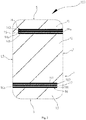
Fig. 2 illustrates a schematic view of an antenna device provided by an example of a first embodiment of the present disclosure; -
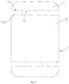
Fig. 3 illustrates a schematic view of an antenna device provided by another example of the first embodiment of the present disclosure; -
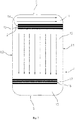
Fig. 4 illustrates a schematic view of an antenna device provided by other embodiments of the present disclosure; -
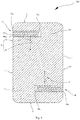
Fig. 5 illustrates a schematic view of another antenna device provided by other embodiments of the present disclosure; -
Fig. 6 illustrates a schematic view of an overall structure of an antenna device, a mainboard in a mobile terminal, a matching circuit and a radio frequency transceiver circuit which are arranged on the mainboard in a housing provided by the first embodiment of the present disclosure; -
Fig. 7 illustrates a schematic view of a current distribution of a housing of an antenna device provided by the first embodiment of the present disclosure; -
Fig. 8 illustrates a schematic view of an antenna device provided by an example of a second embodiment of the present disclosure; -
Fig. 9 illustrates a schematic view of an antenna device provided by another example of the second embodiment of the present disclosure. - Technical solutions in embodiments of the present disclosure will be clearly and completely described with reference to drawings in embodiments of the present disclosure in the following. Obviously, the embodiments described are just a part of embodiments of the present disclosure, rather than all the embodiments. Based on embodiments of the present disclosure, all the other embodiments acquired by those skilled in the art without making creative labors belong to the protection scope of the present disclosure.
- In the specification, it is to be understood that terms such as "left," "right," "upper," "lower," "long," and "short" should be construed to refer to the orientation as then described or as shown in the drawings under discussion. These relative terms are for convenience of description and for simplification of the description, and do not imply or indicate that the referred device or element must have a particular orientation or must be constructed or operated in a particular orientation, and should not be construed as a limitation to the present disclosure thus.
-
Fig. 1 illustrates amobile terminal 10 involved in an embodiment of the present disclosure. Themobile terminal 10 includes an antenna device and themobile terminal 10 may be any device having communication and memory functions, for example, an intelligent device having a network function such as a tablet computer, a mobile phone, an e-reader, a remote control, a personal computer (PC), a laptop computer, a vehicle-mounted device, a network television and a wearable device, etc. Themobile terminal 10 includes the antenna device. The antenna device includes a housing, a radio frequency transceiver circuit and a matching circuit, in which, the housing is generally configured as a rear cover of themobile terminal 10, and a battery and a mainboard are accommodated in the housing. - A specific structure of the antenna device will be described with reference to the antenna device in the following embodiments.
- Referring to
Fig. 2 along withFig. 6 , anantenna device 100 provided by a first embodiment of the present disclosure includes: ahousing 1, a radiofrequency transceiver circuit 2 and a matching circuit 3. The radiofrequency transceiver circuit 2 and the matching circuit 3 are arranged on a mainboard 4 in the mobile terminal, or arranged on a circuit board coupled with the mainboard 4. The matching circuit 3 is electrically connected between the radiofrequency transceiver circuit 2 and thehousing 1, so as to transmit and receive signals. - Referring to
Fig. 2 along withFig. 3 , thehousing 1 includes afirst housing area 11, asecond housing area 12, afirst slit strip 14 and a first connectingsegment 15. Thefirst slit strip 14 is provided with at least onefirst slit 142. Thefirst slit strip 14 and the first connectingsegment 15 are located between thefirst housing area 11 and thesecond housing area 12. Thefirst housing area 11 and thesecond housing area 12 are located at two sides of thefirst slit strip 14 and the first connectingsegment 14 is located at an extending path of thefirst slit strip 14 of thehousing 1. - It could be understood that, the
first slit strip 14 is provided with a plurality offirst slits 142 parallel to and spaced apart from each other. Specifically, thehousing 1 is made from a conducting material which is a whole piece of sheet metal. Thehousing 1 includes a first long side L1 and a second long side L2 which are opposite to each other and a pair of short sides S opposite to each other. The pair of short sides S are opposite to each other and connected between the first long side L1 and the second long side L2. An area of the conducting material on thehousing 1 apart from thefirst slit strip 14 is defined as a metal area. The first connecting segment 115, thefirst housing area 11 and thesecond metal 12 constitutes the metal area. Thefirst slit strip 14 may be cut in from an edge of thehousing 1, but thehousing 1 is not completely cut off, thus allowing the structure of thehousing 1 to be integrated, thereby enabling thehousing 1 to bear a relatively large force. Specifically, a plurality of tinyfirst metal strips 141 are carved on thehousing 1 by means of laser cutting, in which, onefirst slit 142 is defined between two adjacent first metal strips 141, that is, the plurality offirst metal strips 141 parallel to and spaced apart from each other form thefirst slit strip 14. Thehousing 1 is divided into thefirst housing area 11 and thesecond housing area 12 through thefirst slit strip 14. Certainly, in other embodiments, thefirst slit strip 14 may also be formed by cutting via a grinding machine. - It could be understood that, the
first slit 142 is a long rectangular aperture. It could be understood that, thefirst slit 142 in thefirst slit strip 14 may be filled with a non-signal shielding material, such as plastics, thereby further improving the appearance integrity of thehousing 1 while allowing thehousing 1 to have a better waterproofness. Moreover the non-signal shielding material may also transmit the light. When theantenna device 100 is applied to a terminal, a breathing light (not shown) may be arranged in the terminal and corresponding to thefirst slit strip 14, such that light rays of the breathing light can be transmitted through the light-transmitting non-signal shielding material in thefirst slit 142 and the user can observe the light rays of the breathing light from outside of theantenna device 100, thereby knowing operation conditions of the terminal, improving appearance effect of the terminal and improving the user experience. Preferably, the light-transmitting non-signal shielding material adopts a light guiding material, thus allowing thefirst slit strip 14 to present a light strip, thereby improving the appearance effect of theantenna device 100. Certainly, in the other embodiments, as shown inFigs. 4 and5 , thefirst slit strip 14 on thehousing 1 may be provided with only onefirst slit 142. Thefirst slit 142 and the first connectingsegment 15 divide thehousing 1 into thefirst housing area 11 and thesecond housing area 12. - The first connecting
segment 15 is a conducting material (such as a metal material). The first connectingsegment 15 is located at an extending path of thefirst slit strip 14 of thehousing 1, i.e., the first connectingsegment 15 and thefirst slit strip 14 are in the same line on thehousing 1. It could be understood that, the extending path of thefirst slit strip 14 may be straight, i.e., the extending path is at two sides of thefirst slit strip 14 along the direction of the short side S, and may also be at a middle position of thefirst slit strip 14. When the extending path of thefirst slit strip 14 is straight, thefirst slit strip 14 and the first connectingsegment 15 are located between thefirst housing area 11 and thesecond housing area 12, and the extending path makes it easy to produce thefirst slit strip 14 and the first connectingsegment 15 on thehousing 1. It could be understood that, the extending path of thefirst slit strip 14 may also be wavy or curved, and the extending path in these shapes may change a bandwidth of thehousing 1. The first connectingsegment 15 is not only electrically connected between thefirst housing area 11 and thesecond housing area 12, but also serves as a feeding point to be electrically connected with the matching circuit 3, thus allowing the metal area to receive a feed signal, thereby allowing the metal area to radiate an electromagnetic wave, i.e., to act as a radiating body of theantenna device 100, thereby forming an antenna radio frequency, that is, the first connectingsegment 15, thefirst housing area 11 and thesecond housing area 12 server as the radiating body of theantenna device 100. In the meantime, thefirst housing area 11 and thesecond housing area 12 have a large area, thereby allowing theantenna device 100 and a mobile terminal having theantenna device 100 to have the high radiation efficiency. It could be understood that, the first connectingsegment 15 may also serve as a ground point of theantenna device 100, thus achieving a ground connection function of the radiating body of theantenna device 100. It could be understood that, the first connectingsegment 15 is electrically connected with the matching circuit 3 on the mainboard 4 through a resilient metal piece. Certainly, in the other embodiments, thefirst slit 142 may also be in the shape of a wave, lightning or a long oval, etc. - It could be understood that, the plurality of
first metal strips 141 are arranged at equal intervals to each other, and a width of thefirst slit 142 is less than a width of thefirst metal strip 141. Specifically, ratio of the width of thefirst metal strip 141 to the width of thefirst slit 142 is 1.5 to 2.0, such that a proportion of the adjacentfirst slit 142 is small, and a user can't distinguish thefirst slit 142 with his naked eyes, thereby improving the appearance effect of theantenna device 100 on the whole. Preferably, the width of thefirst slit 142 is 0.01mm to 0.5mm. More specifically, the width of thefirst slit 142 is 0.05mm to 0.3mm, and the amount of the first metal strips 141 is more than 5 to 10. The width of the slit between two adjacent first metal strips 141 is ensured to 0.05mm as a minimum, such that thefirst slit 142 can't be directly distinguished by the user and the lowest efficiency of the radio frequency of theantenna device 100 is ensured. On the contrary, the width of thefirst slit 142 is controlled to be 0.3mm as a maximum, such that the efficiency of the radio frequency of theantenna device 100 is improved. Likely, the amount of the first metal strips 141 is controlled to be 5 as a minimum, so as to ensure appearance requirements of theantenna device 100, and the amount of the first metal strips 141 is controlled to be 10 as a maximum, so as to improve the efficiency of the radio frequency of theantenna device 100. The width of thefirst slit strip 14 is 1.5mm to 5.0mm, such that a proportion of thefirst slit strip 14 to theoverall housing 10 is small, thereby improving the appearance effect of theantenna device 100. In the present embodiment, the width of thefirst slit 142 is 0.06mm, thus making thefirst slit 142 invisible to the naked eyes, thereby improving the appearance integrity of thehousing 1. In the other embodiments, the width of thefirst slit 142 may be 0.01mm, the width of thefirst slit 142 may be 0.5mm, the width of thefirst slit 142 may be 0.05mm or the width of thefirst slit 142 may be 0.3mm. Preferably, the amount of thefirst slits 142 may be 2 to 5. In the present disclosure, the amount of thefirst slits 142 is 3, thereby facilitating radiation of theantenna device 100. - In the following the extending path of the
first slit strip 14 being straight is taken as an example. For convenience of description, all the area having the conducting material on thehousing 1 apart from thefirst slit strip 14 is defined as the metal area, and the metal area is configured as a radiation part of theantenna device 100. - It could be understood that, an end of the
first slit strip 14 adjacent to the first connectingsegment 15 is connected with the first connectingsegment 15. - In an embodiment, as illustrated in
Fig. 2 , thefirst slit strip 14 includes a first open end 14a and a firstclosed end 14b opposite to each other. The first open end 14a is located on the first long side L1, and the firstclosed end 14b of thefirst slit strip 14 extends from the first long side L1 to the second long side L2, a part of thehousing 1 between the firstclosed end 14b and the second long side L2 forms the first connectingsegment 15. By arranging thefirst slit strip 14 as the above configuration, the proportion of metal in thehousing 1 is further improved, thereby improving the appearance integrity of thehousing 1 and the mobile terminal. A part of thefirst metal strip 141 at the firstclosed end 14b is directly connected with the first connectingsegment 15, that is, the firstclosed end 14b is not isolated from the first connectingsegment 15. - Further, the
housing 1 further includes athird housing area 13, asecond slit strip 16 and a second connectingsegment 17. Thesecond slit strip 16 is provided with a plurality of second metal strips 161 parallel to and spaced apart from each other, thesecond housing area 12 and thethird housing area 13 are located at two sides of thesecond slit strip 16. The second connectingsegment 17 is arranged at an extending path of thesecond slit strip 16 of thehousing 1. The second connectingsegment 17 is electrically connected between thesecond housing area 12 and thethird housing area 13, and the second connectingsegment 17 is electrically connected with the matching circuit 3. - Specifically, the structure of the
second slit strip 16 may be the same as the structure of thefirst slit strip 14, which will not be elaborated herein. The extending path of thesecond slit strip 16 may be the same as the extending path of thefirst slit strip 14. By adding thesecond slit strip 16 and the second connectingsegment 17, thehousing 1 is divided into thefirst housing area 11, thesecond housing area 12 and thethird housing area 13, that is, three radiation parts are formed on thehousing 1, thereby further improving the radiation efficiency of theantenna device 100 and the mobile terminal. - It could be understood that, the
second slit strip 16 includes a second open end 16a and a secondclosed end 16b opposite to each other, the second open end 16a is located on the second long side L2, the secondclosed end 16b of thesecond slit strip 16 extends from the second long side L2 to the first long side L1. A part of thehousing 1 between the secondclosed end 16b and the first long side L1 forms the second connectingsegment 17. Apart of thesecond metal strip 161 at the secondclosed end 16b is directly connected with the second connectingsegment 17, that is, the secondclosed end 16b is not isolated from the second connectingsegment 17. - In another embodiment, as illustrated
Fig. 3 , thehousing 1 includes the first long side L1 and the second long side L2 which are opposite to each other and a pair of short sides S. The pair of short sides S are opposite to each other and connected between the first long side L1 and the second long side L2. Thefirst slit strip 14 extends from the first long side L1 to the second long side L2, and the first connectingsegment 15 stretches across thefirst slit strip 14. Specifically, thefirst slit strip 14 has two first open ends 14a, and the two first open ends 14a are located on the first long side L1 and the second long side L2 respectively. The first connectingsegment 15 stretches across thefirst slit strip 14. That is, thefirst housing area 11 and thesecond housing area 12 are completed separated by thefirst slit strip 14, and the first connectingsegment 15 is a conducting plate independent of thehousing 1. During the manufacturing, thefirst slit strip 14 is formed firstly, and then the first connectingsegment 15 is fabricated. The first connectingsegment 15 may be located at any position on thefirst slit strip 14. A part of thefirst metal strip 141 adjacent to the first connectingsegment 15 is directly connected with the first connectingsegment 15, and thefirst metal strip 14 is not isolated from the first connectingsegment 15. - Further, the
housing 1 further includes thethird housing area 13, thesecond slit strip 16 and the second connectingsegment 17. Thesecond slit strip 16 is provided with a plurality of second metal strips 161 parallel to and spaced apart from each other. Thesecond housing area 12 and thethird housing area 13 are located at two sides of thesecond slit strip 16. The second connectingsegment 17 is arranged at an extending path of thesecond slit strip 16 of thehousing 1. The second connectingsegment 17 is electrically connected between thesecond housing area 12 and thethird housing area 13, and the second connectingsegment 17 is electrically connected with the matching circuit 3. - Specifically, the structure of the
second slit strip 16 may be the same as the structure of thefirst slit strip 14, which will not be elaborated herein. The extending path of thesecond slit strip 16 may be the same as the extending path of thefirst slit strip 14. By adding thesecond slit strip 16 and the second connectingsegment 17, thehousing 1 is separated into thefirst housing area 11, thesecond housing area 12 and thethird housing area 13, that is, three radiation parts are formed on thehousing 1, thereby further improving the radiation efficiency of theantenna device 100 and the mobile terminal. It could be understood that, thesecond slit strip 16 extends from the first long side L1 to the second long side L2, and the second connectingsegment 17 stretches across thesecond slit strip 16. Apart of thesecond metal strip 161 adjacent to the second connectingsegment 17 is directly connected with the second connectingsegment 17, that is, thesecond metal strip 161 is not isolated from the second connectingsegment 17. - In an embodiment, the
first slit strip 14 is parallel to thesecond slit strip 16. - In embodiments of the present disclosure, the radiating body of
antenna device 100 and the mobile terminal is arranged to thehousing 1 of the mobile terminal, and thehousing 1 is divided into at least two housing areas (thefirst housing area 11, thesecond housing area 12 and the third housing area 13) through the slit strip (thefirst slit strip 14 and/or the second slit strip 16) to form the radiation parts of theantenna device 100. The at least two housing areas are electrically connected through the connecting segment (the first connectingsegment 15 and the second connecting segment 17) and the feed is achieved by electrically connecting the connecting segment with the matching circuit 3 of theantenna device 100. The design of the radiating body ofantenna device 100 and the mobile terminal provided by the present disclosure makes use of the structure of thehousing 1 of the mobile terminal, the radiation area is large and no additional radiating body of an antenna is needed, thereby not only improving the radiation efficiency of theantenna device 100, but also simplifying the overall structure of the mobile terminal, and facilitating reduction of the cost of the mobile terminal. Moreover the slit strip is composed of a plurality of metal strips (thefirst metal strip 141 or the second metal strip 161) parallel to and spaced apart from each other, thus allowing the slit strip to be invisible to the naked eyes, thereby improving the appearance integrity of thehousing 1. - Referring to
Fig. 7, Fig. 7 illustrates a schematic view of a current distribution of thehousing 1 of theantenna device 100. InFig. 6 , the first connectingsegment 15 is connected with the matching circuit 3 to serve as the feeding point, such that the current in thefirst housing area 11 flows from the second long side L2 to the first long side L1, and the current in thesecond housing area 12 flows from thefirst slit strip 14 to a direction perpendicular to thefirst slit strip 14. -
Figs. 8 and9 illustrates anantenna device 200 provided by a second embodiment of the present disclosure. Theantenna device 200 is generally the same as theantenna device 100 provided by the first embodiment. The difference is that an end of thefirst slit strip 14 adjacent to the first connectingsegment 15 is isolated from the first connectingsegment 15, and theantenna device 200 is further provided with a switch 6 for correspondence to the structure of thefirst slit strip 14. The switch 6 is connected with onefirst metal strip 141 of thefirst slit strip 14 and is configured to turn on or off the electrical connection between the radiation part and thefirst metal strip 141. By isolating thefirst metal strip 141 from the metal area of thehousing 1 apart from thefirst slit strip 14, i.e., the radiation part (the first connecting segment, the first housing area and the second housing area), and by using the switch 6 to control a conducting state between thefirst metal strip 141 and the radiation part, a resonance frequency of the radiation part may change, that is, a frequency band of theantenna device 200 increases, thereby increasing the bandwidth and improving the user experience. - It could be understood that, the switch 6 may be a single-pole multi-throw switch, and may also be a single-pole single-throw switch. Specifically, the switch 6 includes a moving
contact 61 and a fixed contact 62, the movingcontact 61 is electrically connected with the radiation part, and the fixed contact 62 is electrically connected with thefirst metal strip 141. The movingcontact 61 may be connected with the fixed contact 62 or disconnected from the fixed contact 62, thereby turning on or off the electrical connection between the radiation part and thefirst metal strip 141. The movingcontact 61 may be connected with a central processing unit of the terminal, so as to be connected with the fixed contact 62 according to a control signal of the terminal. The amount of the fixed contact 62 may be one or more, the one or more fixed contacts 62 may be correspondingly connected to the one or more first metal strips 141. - As shown in
Fig. 8 , the amount of the fixed contact 62 of the switch 6 is one, the one fixed contact 62 is electrically connected with one of the first metal strips 141. When the movingcontact 61 is connected with the fixed contact 62, thefirst metal strip 141 electrically connected with the fixed contact 62 is connected with the radiation part through the movingcontact 61, thereby changing the electromagnetic wave of the radiation part which generates a first resonance frequency. When the fixed contact 62 is disconnected from thefirst metal strip 141, thefirst metal strip 141 is disconnected from the metal area, and the metal area radiates an electromagnetic wave with a second resonance frequency, the second resonance frequency is different from the first resonance frequency, such that the antenna device may produce the electromagnetic signals with different resonance frequencies, thereby increasing the bandwidth and improving the user experience. - As shown in
Fig. 9 , the amount of the fixed contact 62 of the switch 6 is two, the two fixed contacts 62 are electrically connected with two first metal strips 141, the movingcontact 61 is connected with or disconnected from one of the fixed contacts 62. Specifically, the two fixed contacts 62 are a first fixed contact 621 and a second fixed contact 622 respectively. The plurality offirst metal strips 141 include one first metal strip 1411 and anotherfirst metal strip 1412. The twofirst metal strips 141 are adjacent to each other. Compared with the other onefirst metal strip 1412, the one first metal strip 1411 is more adjacent to thesecond housing area 12, that is, distance from the one first metal strip 1411 to thesecond housing area 12 is less than distance from the other onefirst metal strip 1412 to thesecond housing area 12. The first fixed contact 621 is electrically connected with the onefirst metal strip 141, and the second fixed contact 622 is electrically connected with the other onefirst metal strip 1412. When the movingcontact 61 is connected with the one first metal strip 1411, the radiation part radiates the electromagnetic wave with the first resonance frequency. When the movingcontact 61 is connected with the other onefirst metal strip 1412, the slit dimension between the other onefirst metal strip 1412 and thesecond radiation part 12 is larger than the slit dimension between the onefirst metal strip 141 and the radiation part, thereby changing the resonance frequency radiated by the radiation part, that is, the radiation part radiates an electromagnetic wave with a third resonance frequency and the third resonance frequency is different from the first resonance frequency and the second resonance frequency. Theantenna device 200 can further radiate more electromagnetic waves with different resonance frequencies, thereby achieving more frequency bands and making it more convenient for the user to select among different frequency bands, and further increasing the bandwidth of the antenna. Likely, in the other embodiments, a plurality of fixed contacts 62 correspondingly and electrically connected to the plurality of first metal strips 141 may also be provided, thus resulting in different resonance frequencies radiated by the radiation part according to the slit of different dimensions formed between eachfirst metal strip 141 and the radiation part, thereby achieving more frequency bands and providing more selections of frequency band for the user. - In an embodiment, as illustrated in
Fig. 8 , thefirst slit strip 14 includes the first open end 14a and the firstclosed end 14b opposite to each other. The first open end 14a is located on the first long side L1, and the firstclosed end 14b of thefirst slit strip 14 extends from the first long side L1 to the second long side L2, a part of thehousing 1 between the firstclosed end 14b and the second long side L2 forms the first connectingsegment 15. By arranging thefirst slit strip 14 as the above configuration, the proportion of metal in thehousing 1 is further improved, thereby improving the appearance integrity of thehousing 1 and the mobile terminal. The part of thefirst metal strip 141 at the firstclosed end 14b is isolated from the first connectingsegment 15, that is, the firstclosed end 14b is isolated from the first connectingsegment 15. - Further, the
housing 1 further includes thethird housing area 13, thesecond slit strip 16 and the second connectingsegment 17. Thesecond slit strip 16 is provided with a plurality of second metal strips 161 parallel to and spaced apart from each other, thesecond housing area 12 and thethird housing area 13 are located at two sides of thesecond slit strip 16. The second connectingsegment 17 is arranged at an extending path of thesecond slit strip 16 of thehousing 1. The second connectingsegment 17 is electrically connected between thesecond housing area 12 and thethird housing area 13, and the second connectingsegment 17 is electrically connected with the matching circuit 3. - Specifically, the structure of the
second slit strip 16 may be the same as the structure of thefirst slit strip 14, which will not be elaborated herein. The extending path of thesecond slit strip 16 may be the same as the extending path of thefirst slit strip 14. By adding thesecond slit strip 16 and the second connectingsegment 17, thehousing 1 is divided into thefirst housing area 11, thesecond housing area 12 and thethird housing area 13, that is, three radiation parts are formed on thehousing 1, thereby further improving the radiation efficiency of theantenna device 100 and the mobile terminal. - It could be understood that, the
second slit strip 16 includes the second open end 16a and the secondclosed end 16b opposite to each other, the second open end 16a is located on the second long side L2, the secondclosed end 16b of thesecond slit strip 16 extends from the second long side L2 to the first long side L1. A part of thehousing 1 between the secondclosed end 16b and the first long side L1 forms the second connectingsegment 17. The part of thesecond metal strip 161 at the secondclosed end 16b is directly connected with the second connectingsegment 17, that is, the secondclosed end 16b is in not isolated from the second connectingsegment 17. - In another embodiment, as illustrated in
Fig. 9 , thehousing 1 includes the first long side L1 and the secondlong side 12 which are opposite to each other and a pair of short sides S. The short sides S are opposite to each other and connected between the first long side L1 and the second long side L2. Thefirst slit strip 14 extends from the first long side L1 to the second long side L2, and the first connectingsegment 15 stretches across thefirst slit strip 14. Specifically, thefirst slit strip 14 has two first open ends 14a, and the two first open ends 14a are located on the first long side L1 and the second long side L2 respectively. The first connectingsegment 15 stretches across thefirst slit strip 14. That is, thefirst housing area 11 and thesecond housing area 12 are completed separated by thefirst slit strip 14, and the first connectingsegment 15 is a conducting plate independent of thehousing 1. During the manufacturing, thefirst slit strip 14 is formed firstly, and then the first connectingsegment 15 is fabricated. The first connectingsegment 15 may be located at any position on thefirst slit strip 14. The part of thefirst metal strip 141 adjacent to the first connectingsegment 15 is isolated from the first connectingsegment 15, and thefirst metal strip 14 is isolated from the first connectingsegment 15. - Further, the
housing 1 further includes thethird housing area 13, thesecond slit strip 16 and the second connectingsegment 17. Thesecond slit strip 16 is provided with a plurality of second metal strips 161 parallel to and spaced apart from each other. Thesecond housing area 12 and thethird housing area 13 are located at two sides of thesecond slit strip 16. The second connectingsegment 17 is arranged at an extending path of thesecond slit strip 16 of thehousing 1. The second connectingsegment 17 is electrically connected between thesecond housing area 12 and thethird housing area 13, and the second connectingsegment 17 is electrically connected with the matching circuit 3. - Specifically, the structure of the
second slit strip 16 may be the same as the structure of thefirst slit strip 14, which will not be elaborated herein. The extending path of thesecond slit strip 16 may be the same as the extending path of thefirst slit strip 14. By adding thesecond slit strip 16 and the second connectingsegment 17, thehousing 1 is divided into thefirst housing area 11, thesecond housing area 12 and thethird housing area 13, that is, three radiation parts are formed on thehousing 1, thereby further improving the radiation efficiency of theantenna device 100 and the mobile terminal. It could be understood that, thesecond slit strip 16 extends from the first long side L1 to the second long side L2, and the second connectingsegment 17 stretches across thesecond slit strip 16. Apart of thesecond metal strip 161 adjacent to the second connectingsegment 17 is isolated from the second connectingsegment 17, that is, thesecond metal strip 161 is isolated from the second connectingsegment 17. - In an embodiment, the
first slit strip 14 is parallel to thesecond slit strip 16. - In embodiments of the present disclosure, the radiating body of
antenna device 200 and the mobile terminal is arranged to thehousing 1 of the mobile terminal, and thehousing 1 is divided into at least two housing areas (thefirst housing area 11, thesecond housing area 12 and the third housing area 13) through the slit strip (thefirst slit strip 14 and/or the second slit strip 16) to form the radiation part of theantenna device 200. The at least two housing areas are electrically connected through the connecting segment (the first connectingsegment 15 and the second connecting segment 17) and the feed is achieved by electrically connecting the connecting segment with the matching circuit 3 of theantenna device 200. - The radiating body of
antenna device 200 and the mobile terminal provided by the present disclosure is designed by making use of the structure of thehousing 1 of the mobile terminal, the radiation area is large and no additional radiating body of an antenna is needed, thereby not only improving the radiation efficiency of theantenna device 200, but also simplifying the overall structure of the mobile terminal, and facilitating reduction of the cost of the mobile terminal. Moreover the slit strip is composed of a plurality of metal strips (thefirst metal strip 141 or the second metal strip 161) parallel to and spaced apart from each other, thus allowing the slit strip to be invisible to the naked eyes, thereby improving the appearance integrity of thehousing 1. - In the
antenna device 200 according to embodiments of the present disclosure, by isolating thefirst metal strip 161 from the metal area of thehousing 1 apart from thefirst slit strip 14, i.e., the radiation part (the first connecting segment, the first housing area and the second housing area), and by using the switch 6 to control a conducting state between thefirst metal strip 141 and the radiation part, a resonance frequency of the radiation part may change, that is, a frequency band of theantenna device 200 increases, thereby increasing the bandwidth and improving the user experience. - The embodiments of the present disclosure are described in detail in the above. Specific examples are applied to the present specification to explain principles and embodiments of the present disclosure, the description of the above embodiment is just for understanding method and the core thoughts of the present disclosure. In the meantime, to those skilled in the art, based on the thoughts of the present disclosure, there may be a change within the scope of the embodiments and the application. From the above, details of the present disclosure should not be construed to limit the present disclosure.
Claims (30)
- A housing comprising a first housing area, a second housing area, a first slit strip and a first connecting segment, the first slit strip provided with at least one first slit, the first housing area and the second housing area being located at two sides of the first slit strip and the first connecting segment is located at an extending path of the first slit strip of the housing.
- The housing according to claim 1, wherein the first slit strip has an end adjacent to the first connecting segment and isolated from the first connecting segment.
- The housing according to claim 1, wherein the first slit strip has an end adjacent to the first connecting segment and connected with the first connecting segment.
- The housing according to claim 2 or 3, wherein the housing comprises a first long side and a second long side which are opposite to each other and a pair of short sides, the pair of short sides are opposite to each other and connected between the first long side and the second long side, the first slit strip comprises a first open end and a first closed end opposite to each other, the first open end is located on the first long side, and the first closed end of the first slit strip extends from the first long side to the second long side, the housing comprises a part between the first closed end and the second long side, and the part is the first connecting segment.
- The housing according to claim 2 or 3, wherein the housing comprises a first long side and a second long side which are opposite to each other and a pair of short sides, the pair of short sides are opposite to each other and connected between the first long side and the second long side, the first slit strip extends from the first long side to the second long side, and the first connecting segment stretches across the first slit strip.
- The housing according to claim 1, wherein the amount of the first slit is one.
- The housing according to claim 1, wherein the amount of the first slit is at least two, the at least two first slits are parallel to and spaced apart from each other, a first metal strip is provided between the two adjacent first slits.
- The housing according to claim 7, wherein a width of the first slit is 0.01mm; or
the width of the first slit is 0.5mm; or
the width of the first slit is 0.01mm to 0.5mm. - The housing according to claim 7, wherein the amount of the first metal strip is 2 to 5.
- The housing according to claim 1, wherein the first slit is filled with a non-signal shielding material.
- The housing according to claim 1, wherein the housing further comprises a third housing area, a second slit strip and a second connecting segment, the second slit strip defines at least one second slit, the second housing area and the third housing area are located at two sides of the second slit strip, the second connecting segment is arranged at an extending path of the second slit strip of the housing.
- The housing according to claim 11, wherein the housing comprises a first long side and a second long side which are opposite to each other and a pair of short sides, the pair of short sides are opposite to each other and connected between the first long side and the second long side, the first slit strip comprises a first open end and a first closed end opposite to each other, the first open end is located on the first long side, and the first closed end of the first slit strip extends from the first long side to the second long side, the housing comprises a part between the first closed end and the second long side, and the part is the first connecting segment; the second slit strip comprises a second open end and a second closed end opposite to each other, the second open end is located on the second long side, the second closed end of the second slit strip extends from the second long side to the first long side, the housing comprises another part between the second closed end and the first long side, and the other part is the second connecting segment.
- The housing according to claim 11, wherein the housing comprises a first long side and a second long side which are opposite to each other and a pair of short sides, the pair of short sides are opposite to each other and connected between the first long side and the second long side, the first slit strip and the second slit strip extend from the first long side to the second long side, the first connecting segment stretches across the first slit strip and the second connecting segment stretches across the second slit strip.
- The housing according to claim 11, wherein the first slit strip is parallel to the second slit strip.
- An antenna device comprising a radio frequency transceiver circuit, a matching circuit and a housing, the housing is made from a conducting material, the housing comprises a first housing area, a second housing area, a first slit strip and a first connecting segment, the first slit strip is provided with at least one first slit, the first housing area and the second housing area are located at two sides of the first slit strip and the first connecting segment is located at an extending path of the first slit strip of the housing, the matching circuit is electrically connected between the radio frequency transceiver circuit and the housing, the first connecting segment is electrically connected between the first housing area and the second housing area, the first housing area and the second housing area each are metal materials, the first connecting segment is electrically connected with the matching circuit, so as to allow the first connecting segment, the first housing area and the second housing area to serve as a radiation part.
- The antenna device according to claim 15, wherein the housing comprises a first long side and a second long side which are opposite to each other and a pair of short sides, the pair of short sides are opposite to each other and connected between the first long side and the second long side, the first slit strip comprises a first open end and a first closed end opposite to each other, the first open end is located on the first long side, and the first closed end of the first slit strip extends from the first long side to the second long side, the housing comprises a part between the first closed end and the second long side, and the part is the first connecting segment.
- The antenna device according to claim 15, wherein the housing comprises a first long side and a second long side which are opposite to each other and a pair of short sides, the pair of short sides are opposite to each other and connected between the first long side and the second long side, the first slit strip extends from the first long side to the second long side, and the first connecting segment stretches across the first slit strip.
- The antenna device according to claim 15, wherein the amount of the first slit is one.
- The antenna device according to claim 15, wherein the amount of the first slit is at least two, the at least two first slits are parallel to and spaced apart from each other, a first metal strip is provided between the two adjacent first slits.
- The antenna device according to claim 18 or 19, wherein the first slit strip has an end adjacent to the first connecting segment and connected with the first connecting segment.
- The antenna device according to claim 19, wherein the first slit strip has an end adjacent to the first connecting segment and isolated from the first connecting segment.
- The antenna device according to claim 21, wherein the antenna device further comprises a switch, the switch is connected with one first metal strip of the first slit strip and is configured to turn on or off electrical connection between the radiation part and the first metal strip.
- The antenna device according to claim 22, wherein the switch comprises a moving contact and a fixed contact, the moving contact is electrically connected with the radiation part, and the fixed contact is electrically connected with the first metal strip, the moving contact is connected with the fixed contact or disconnected from the fixed contact, thereby turning on or off the electrical connection between the radiation part and the first metal strip.
- The antenna device according to claim 23, wherein the amount of the fixed contact of the switch is one, the one fixed contact is electrically connected with one first metal strip.
- The antenna device according to claim 23, wherein the amount of the fixed contact of the switch is two, the two fixed contacts are electrically connected with two first metal strips.
- The antenna device according to claim 15, wherein the first slit is filled with a non-signal shielding material.
- The antenna device according to claim 15, wherein the housing further comprises a third housing area, a second slit strip and a second connecting segment, the second slit strip defines at least one second slit, the second housing area and the third housing area are located at two sides of the second slit strip, the second connecting segment is arranged at an extending path of the second slit strip of the housing, the second connecting segment is electrically connected between the second housing area and the third housing area, and the second connecting segment is electrically connected with the matching circuit.
- The antenna device according to claim 27, wherein the housing comprises a first long side and a second long side which are opposite to each other and a pair of short sides, the pair of short sides are opposite to each other and connected between the first long side and the second long side, the first slit strip comprises a first open end and a first closed end opposite to each other, the first open end is located on the first long side, and the first closed end of the first slit strip extends from the first long side to the second long side, the housing comprises a part between the first closed end and the second long side, the part is the first connecting segment; the second slit strip comprises a second open end and a second closed end opposite to each other, the second open end is located on the second long side, the second closed end of the second slit strip extends from the second long side to the first long side, the housing comprises another part between the second closed end and the first long side, and the other part is the second connecting segment.
- The antenna device according to claim 27, wherein the housing comprises a first long side and a second long side which are opposite to each other and a pair of short sides, the pair of short sides are opposite to each other and connected between the first long side and the second long side, the first slit strip and the second slit strip extend from the first long side to the second long side, the first connecting segment stretches across the first slit strip and the second connecting segment stretches across the second slit strip.
- A mobile terminal comprising the antenna device according to any one of claims 15 to 29.
Applications Claiming Priority (4)
| Application Number | Priority Date | Filing Date | Title |
|---|---|---|---|
| CN201610163702.0A CN105655701B (en) | 2016-03-21 | 2016-03-21 | Antenna device and mobile terminal |
| CN201610287147.2A CN105762493B (en) | 2016-04-29 | 2016-04-29 | Metal shell, antenna device and mobile terminal |
| CN201610287114.8A CN105789833B (en) | 2016-04-29 | 2016-04-29 | Antenna device and mobile terminal |
| PCT/CN2016/086566 WO2017161713A1 (en) | 2016-03-21 | 2016-06-21 | Housing, antenna apparatus and mobile terminal |
Publications (3)
| Publication Number | Publication Date |
|---|---|
| EP3273536A1 true EP3273536A1 (en) | 2018-01-24 |
| EP3273536A4 EP3273536A4 (en) | 2018-05-23 |
| EP3273536B1 EP3273536B1 (en) | 2019-08-14 |
Family
ID=59899269
Family Applications (1)
| Application Number | Title | Priority Date | Filing Date |
|---|---|---|---|
| EP16895065.7A Active EP3273536B1 (en) | 2016-03-21 | 2016-06-21 | Housing, antenna apparatus and mobile terminal |
Country Status (4)
| Country | Link |
|---|---|
| US (1) | US10886597B2 (en) |
| EP (1) | EP3273536B1 (en) |
| ES (1) | ES2746203T3 (en) |
| WO (1) | WO2017161713A1 (en) |
Families Citing this family (4)
| Publication number | Priority date | Publication date | Assignee | Title |
|---|---|---|---|---|
| KR102393808B1 (en) * | 2017-06-20 | 2022-05-04 | 삼성전자주식회사 | An electronic device comprising antenna |
| KR102486184B1 (en) * | 2018-07-06 | 2023-01-10 | 삼성전자주식회사 | Antenna structure and electronic device including the same |
| CN109244664A (en) * | 2018-09-30 | 2019-01-18 | 联想(北京)有限公司 | A kind of electronic equipment |
| KR102682163B1 (en) * | 2019-07-05 | 2024-07-08 | 삼성전자주식회사 | Antenna structure and electronic device including the same |
Family Cites Families (24)
| Publication number | Priority date | Publication date | Assignee | Title |
|---|---|---|---|---|
| TW541759B (en) | 2002-07-24 | 2003-07-11 | Ind Tech Res Inst | Foldable dual-band monopole antenna |
| US8373610B2 (en) * | 2007-12-18 | 2013-02-12 | Apple Inc. | Microslot antennas for electronic devices |
| WO2010073723A1 (en) * | 2008-12-25 | 2010-07-01 | 京セラ株式会社 | Portable terminal |
| CN102349196B (en) * | 2009-03-30 | 2014-10-22 | 日本电气株式会社 | Slot antenna, electronic apparatus, and method for manufacturing slot antenna |
| US8711044B2 (en) * | 2009-11-12 | 2014-04-29 | Nokia Corporation | Antenna arrangement and antenna housing |
| US8610629B2 (en) * | 2010-05-27 | 2013-12-17 | Apple Inc. | Housing structures for optimizing location of emitted radio-frequency signals |
| US9300033B2 (en) * | 2011-10-21 | 2016-03-29 | Futurewei Technologies, Inc. | Wireless communication device with an antenna adjacent to an edge of the device |
| WO2013064872A1 (en) * | 2011-10-31 | 2013-05-10 | Sony Ericsson Mobile Communications Ab | Multiple-input multiple-output (mimo) antennas with multi-band wave traps |
| US9350069B2 (en) * | 2012-01-04 | 2016-05-24 | Apple Inc. | Antenna with switchable inductor low-band tuning |
| US9203139B2 (en) * | 2012-05-04 | 2015-12-01 | Apple Inc. | Antenna structures having slot-based parasitic elements |
| US9122966B2 (en) * | 2012-09-07 | 2015-09-01 | Lawrence F. Glaser | Communication device |
| US9716307B2 (en) * | 2012-11-08 | 2017-07-25 | Htc Corporation | Mobile device and antenna structure |
| CN103280623B (en) | 2013-05-27 | 2017-02-22 | 努比亚技术有限公司 | Antenna structure |
| US9960489B2 (en) * | 2013-08-23 | 2018-05-01 | Samsung Electronics Co., Ltd. | Electronic device and method of operating the same |
| TWI557984B (en) * | 2014-03-05 | 2016-11-11 | 緯創資通股份有限公司 | Wearable device |
| SG11201610762PA (en) * | 2014-03-28 | 2017-02-27 | Huawei Device Co Ltd | Integrated structure of metal housing and antenna of electronic apparatus |
| CN203775569U (en) * | 2014-03-28 | 2014-08-13 | 华为终端有限公司 | Electronic device and metal housing thereof |
| CN203886669U (en) | 2014-05-21 | 2014-10-22 | 国电环境保护研究院 | Flexible anode tensioning fixing device of wet electric dust remover |
| CN204216211U (en) * | 2014-11-12 | 2015-03-18 | 瑞声声学科技(苏州)有限公司 | Communication terminal |
| CN205081217U (en) | 2015-10-23 | 2016-03-09 | 广东欧珀移动通信有限公司 | Slot antenna and cell -phone of cell -phone |
| CN205092313U (en) | 2015-11-05 | 2016-03-16 | 广东欧珀移动通信有限公司 | Metal casing antenna device and mobile terminal |
| CN105337036B (en) | 2015-11-12 | 2018-09-07 | 深圳市万普拉斯科技有限公司 | Mobile terminal and its antenna structure |
| CN105655701B (en) * | 2016-03-21 | 2018-03-02 | 广东欧珀移动通信有限公司 | Antenna device and mobile terminal |
| CN205657165U (en) | 2016-04-29 | 2016-10-19 | 广东欧珀移动通信有限公司 | Antenna device and mobile terminal |
-
2016
- 2016-06-21 EP EP16895065.7A patent/EP3273536B1/en active Active
- 2016-06-21 ES ES16895065T patent/ES2746203T3/en active Active
- 2016-06-21 WO PCT/CN2016/086566 patent/WO2017161713A1/en not_active Ceased
-
2017
- 2017-10-31 US US15/798,823 patent/US10886597B2/en not_active Expired - Fee Related
Also Published As
| Publication number | Publication date |
|---|---|
| US10886597B2 (en) | 2021-01-05 |
| EP3273536A4 (en) | 2018-05-23 |
| ES2746203T3 (en) | 2020-03-05 |
| US20180069293A1 (en) | 2018-03-08 |
| EP3273536B1 (en) | 2019-08-14 |
| WO2017161713A1 (en) | 2017-09-28 |
Similar Documents
| Publication | Publication Date | Title |
|---|---|---|
| EP3331096B1 (en) | Metal housing, antenna device, and mobile terminal | |
| US11848483B2 (en) | Wireless communication device with an antenna adjacent to an edge of the device | |
| EP3333977B1 (en) | Metal terminal rear cover and terminal | |
| US10276938B2 (en) | Mobile terminal device | |
| EP3139438B1 (en) | Integrated structure of metal shell and antenna of electronic device | |
| EP2624363B1 (en) | Wireless communication device and communication terminal apparatus | |
| CN113517556B (en) | Antenna structure and electronic equipment with same | |
| EP3067986B1 (en) | Antenna structure and mobile terminal device | |
| CN104253310B (en) | Multiaerial system and mobile terminal | |
| JP2020527310A (en) | Antennas and mobile terminals | |
| US10886597B2 (en) | Housing, antenna device and mobile terminal | |
| CN110970709B (en) | Antenna structure and wireless communication device with same | |
| CN105789833B (en) | Antenna device and mobile terminal | |
| CN107834173B (en) | Metal case, antenna device and mobile terminal | |
| CN205657168U (en) | Metal casing , antenna device and mobile terminal | |
| CN105811076A (en) | High-isolation mobile phone antenna structure based on metal back cover | |
| KR101600268B1 (en) | Mobile electronic device | |
| CN205509002U (en) | High isolation cell -phone antenna structure based on metal backing lid | |
| CN103700934A (en) | Antenna structure for metal case terminal and terminal | |
| CN205657165U (en) | Antenna device and mobile terminal | |
| CN207800901U (en) | A kind of all-metal tablet integrated antennas | |
| CN112886199B (en) | Four-in-one antenna assembly and tablet personal computer | |
| CN208522082U (en) | A kind of antenna and mobile terminal | |
| CN120149787A (en) | Antennas and electronic equipment | |
| CN113922058A (en) | Electronic device |
Legal Events
| Date | Code | Title | Description |
|---|---|---|---|
| STAA | Information on the status of an ep patent application or granted ep patent |
Free format text: STATUS: THE INTERNATIONAL PUBLICATION HAS BEEN MADE |
|
| PUAI | Public reference made under article 153(3) epc to a published international application that has entered the european phase |
Free format text: ORIGINAL CODE: 0009012 |
|
| STAA | Information on the status of an ep patent application or granted ep patent |
Free format text: STATUS: REQUEST FOR EXAMINATION WAS MADE |
|
| 17P | Request for examination filed |
Effective date: 20171019 |
|
| AK | Designated contracting states |
Kind code of ref document: A1 Designated state(s): AL AT BE BG CH CY CZ DE DK EE ES FI FR GB GR HR HU IE IS IT LI LT LU LV MC MK MT NL NO PL PT RO RS SE SI SK SM TR |
|
| AX | Request for extension of the european patent |
Extension state: BA ME |
|
| REG | Reference to a national code |
Ref country code: DE Ref legal event code: R079 Ref document number: 602016018819 Country of ref document: DE Free format text: PREVIOUS MAIN CLASS: H01Q0001360000 Ipc: H01Q0001440000 |
|
| RAP1 | Party data changed (applicant data changed or rights of an application transferred) |
Owner name: GUANGDONG OPPO MOBILE TELECOMMUNICATIONS CORP., LT |
|
| A4 | Supplementary search report drawn up and despatched |
Effective date: 20180425 |
|
| RIC1 | Information provided on ipc code assigned before grant |
Ipc: H01Q 21/28 20060101ALI20180419BHEP Ipc: H01Q 1/24 20060101ALI20180419BHEP Ipc: H05K 5/04 20060101ALI20180419BHEP Ipc: H01Q 1/44 20060101AFI20180419BHEP |
|
| STAA | Information on the status of an ep patent application or granted ep patent |
Free format text: STATUS: EXAMINATION IS IN PROGRESS |
|
| 17Q | First examination report despatched |
Effective date: 20181023 |
|
| GRAP | Despatch of communication of intention to grant a patent |
Free format text: ORIGINAL CODE: EPIDOSNIGR1 |
|
| STAA | Information on the status of an ep patent application or granted ep patent |
Free format text: STATUS: GRANT OF PATENT IS INTENDED |
|
| DAX | Request for extension of the european patent (deleted) | ||
| INTG | Intention to grant announced |
Effective date: 20190418 |
|
| DAV | Request for validation of the european patent (deleted) | ||
| GRAS | Grant fee paid |
Free format text: ORIGINAL CODE: EPIDOSNIGR3 |
|
| GRAA | (expected) grant |
Free format text: ORIGINAL CODE: 0009210 |
|
| STAA | Information on the status of an ep patent application or granted ep patent |
Free format text: STATUS: THE PATENT HAS BEEN GRANTED |
|
| AK | Designated contracting states |
Kind code of ref document: B1 Designated state(s): AL AT BE BG CH CY CZ DE DK EE ES FI FR GB GR HR HU IE IS IT LI LT LU LV MC MK MT NL NO PL PT RO RS SE SI SK SM TR |
|
| REG | Reference to a national code |
Ref country code: GB Ref legal event code: FG4D |
|
| REG | Reference to a national code |
Ref country code: CH Ref legal event code: EP Ref country code: AT Ref legal event code: REF Ref document number: 1168113 Country of ref document: AT Kind code of ref document: T Effective date: 20190815 |
|
| REG | Reference to a national code |
Ref country code: NL Ref legal event code: FP Ref country code: IE Ref legal event code: FG4D |
|
| REG | Reference to a national code |
Ref country code: DE Ref legal event code: R096 Ref document number: 602016018819 Country of ref document: DE |
|
| RAP2 | Party data changed (patent owner data changed or rights of a patent transferred) |
Owner name: GUANGDONG OPPO MOBILE TELECOMMUNICATIONS CORP., LT |
|
| REG | Reference to a national code |
Ref country code: LT Ref legal event code: MG4D |
|
| PG25 | Lapsed in a contracting state [announced via postgrant information from national office to epo] |
Ref country code: FI Free format text: LAPSE BECAUSE OF FAILURE TO SUBMIT A TRANSLATION OF THE DESCRIPTION OR TO PAY THE FEE WITHIN THE PRESCRIBED TIME-LIMIT Effective date: 20190814 Ref country code: PT Free format text: LAPSE BECAUSE OF FAILURE TO SUBMIT A TRANSLATION OF THE DESCRIPTION OR TO PAY THE FEE WITHIN THE PRESCRIBED TIME-LIMIT Effective date: 20191216 Ref country code: SE Free format text: LAPSE BECAUSE OF FAILURE TO SUBMIT A TRANSLATION OF THE DESCRIPTION OR TO PAY THE FEE WITHIN THE PRESCRIBED TIME-LIMIT Effective date: 20190814 Ref country code: HR Free format text: LAPSE BECAUSE OF FAILURE TO SUBMIT A TRANSLATION OF THE DESCRIPTION OR TO PAY THE FEE WITHIN THE PRESCRIBED TIME-LIMIT Effective date: 20190814 Ref country code: LT Free format text: LAPSE BECAUSE OF FAILURE TO SUBMIT A TRANSLATION OF THE DESCRIPTION OR TO PAY THE FEE WITHIN THE PRESCRIBED TIME-LIMIT Effective date: 20190814 Ref country code: NO Free format text: LAPSE BECAUSE OF FAILURE TO SUBMIT A TRANSLATION OF THE DESCRIPTION OR TO PAY THE FEE WITHIN THE PRESCRIBED TIME-LIMIT Effective date: 20191114 Ref country code: BG Free format text: LAPSE BECAUSE OF FAILURE TO SUBMIT A TRANSLATION OF THE DESCRIPTION OR TO PAY THE FEE WITHIN THE PRESCRIBED TIME-LIMIT Effective date: 20191114 |
|
| REG | Reference to a national code |
Ref country code: AT Ref legal event code: MK05 Ref document number: 1168113 Country of ref document: AT Kind code of ref document: T Effective date: 20190814 |
|
| PG25 | Lapsed in a contracting state [announced via postgrant information from national office to epo] |
Ref country code: AL Free format text: LAPSE BECAUSE OF FAILURE TO SUBMIT A TRANSLATION OF THE DESCRIPTION OR TO PAY THE FEE WITHIN THE PRESCRIBED TIME-LIMIT Effective date: 20190814 Ref country code: IS Free format text: LAPSE BECAUSE OF FAILURE TO SUBMIT A TRANSLATION OF THE DESCRIPTION OR TO PAY THE FEE WITHIN THE PRESCRIBED TIME-LIMIT Effective date: 20191214 Ref country code: RS Free format text: LAPSE BECAUSE OF FAILURE TO SUBMIT A TRANSLATION OF THE DESCRIPTION OR TO PAY THE FEE WITHIN THE PRESCRIBED TIME-LIMIT Effective date: 20190814 Ref country code: LV Free format text: LAPSE BECAUSE OF FAILURE TO SUBMIT A TRANSLATION OF THE DESCRIPTION OR TO PAY THE FEE WITHIN THE PRESCRIBED TIME-LIMIT Effective date: 20190814 Ref country code: GR Free format text: LAPSE BECAUSE OF FAILURE TO SUBMIT A TRANSLATION OF THE DESCRIPTION OR TO PAY THE FEE WITHIN THE PRESCRIBED TIME-LIMIT Effective date: 20191115 |
|
| REG | Reference to a national code |
Ref country code: ES Ref legal event code: FG2A Ref document number: 2746203 Country of ref document: ES Kind code of ref document: T3 Effective date: 20200305 |
|
| PG25 | Lapsed in a contracting state [announced via postgrant information from national office to epo] |
Ref country code: TR Free format text: LAPSE BECAUSE OF FAILURE TO SUBMIT A TRANSLATION OF THE DESCRIPTION OR TO PAY THE FEE WITHIN THE PRESCRIBED TIME-LIMIT Effective date: 20190814 |
|
| PG25 | Lapsed in a contracting state [announced via postgrant information from national office to epo] |
Ref country code: RO Free format text: LAPSE BECAUSE OF FAILURE TO SUBMIT A TRANSLATION OF THE DESCRIPTION OR TO PAY THE FEE WITHIN THE PRESCRIBED TIME-LIMIT Effective date: 20190814 Ref country code: PL Free format text: LAPSE BECAUSE OF FAILURE TO SUBMIT A TRANSLATION OF THE DESCRIPTION OR TO PAY THE FEE WITHIN THE PRESCRIBED TIME-LIMIT Effective date: 20190814 Ref country code: AT Free format text: LAPSE BECAUSE OF FAILURE TO SUBMIT A TRANSLATION OF THE DESCRIPTION OR TO PAY THE FEE WITHIN THE PRESCRIBED TIME-LIMIT Effective date: 20190814 Ref country code: EE Free format text: LAPSE BECAUSE OF FAILURE TO SUBMIT A TRANSLATION OF THE DESCRIPTION OR TO PAY THE FEE WITHIN THE PRESCRIBED TIME-LIMIT Effective date: 20190814 Ref country code: DK Free format text: LAPSE BECAUSE OF FAILURE TO SUBMIT A TRANSLATION OF THE DESCRIPTION OR TO PAY THE FEE WITHIN THE PRESCRIBED TIME-LIMIT Effective date: 20190814 |
|
| PG25 | Lapsed in a contracting state [announced via postgrant information from national office to epo] |
Ref country code: CZ Free format text: LAPSE BECAUSE OF FAILURE TO SUBMIT A TRANSLATION OF THE DESCRIPTION OR TO PAY THE FEE WITHIN THE PRESCRIBED TIME-LIMIT Effective date: 20190814 Ref country code: IS Free format text: LAPSE BECAUSE OF FAILURE TO SUBMIT A TRANSLATION OF THE DESCRIPTION OR TO PAY THE FEE WITHIN THE PRESCRIBED TIME-LIMIT Effective date: 20200224 Ref country code: SM Free format text: LAPSE BECAUSE OF FAILURE TO SUBMIT A TRANSLATION OF THE DESCRIPTION OR TO PAY THE FEE WITHIN THE PRESCRIBED TIME-LIMIT Effective date: 20190814 Ref country code: SK Free format text: LAPSE BECAUSE OF FAILURE TO SUBMIT A TRANSLATION OF THE DESCRIPTION OR TO PAY THE FEE WITHIN THE PRESCRIBED TIME-LIMIT Effective date: 20190814 |
|
| REG | Reference to a national code |
Ref country code: DE Ref legal event code: R097 Ref document number: 602016018819 Country of ref document: DE |
|
| PLBE | No opposition filed within time limit |
Free format text: ORIGINAL CODE: 0009261 |
|
| STAA | Information on the status of an ep patent application or granted ep patent |
Free format text: STATUS: NO OPPOSITION FILED WITHIN TIME LIMIT |
|
| PG2D | Information on lapse in contracting state deleted |
Ref country code: IS |
|
| 26N | No opposition filed |
Effective date: 20200603 |
|
| PG25 | Lapsed in a contracting state [announced via postgrant information from national office to epo] |
Ref country code: SI Free format text: LAPSE BECAUSE OF FAILURE TO SUBMIT A TRANSLATION OF THE DESCRIPTION OR TO PAY THE FEE WITHIN THE PRESCRIBED TIME-LIMIT Effective date: 20190814 |
|
| PG25 | Lapsed in a contracting state [announced via postgrant information from national office to epo] |
Ref country code: MC Free format text: LAPSE BECAUSE OF FAILURE TO SUBMIT A TRANSLATION OF THE DESCRIPTION OR TO PAY THE FEE WITHIN THE PRESCRIBED TIME-LIMIT Effective date: 20190814 |
|
| REG | Reference to a national code |
Ref country code: CH Ref legal event code: PL |
|
| PG25 | Lapsed in a contracting state [announced via postgrant information from national office to epo] |
Ref country code: LU Free format text: LAPSE BECAUSE OF NON-PAYMENT OF DUE FEES Effective date: 20200621 |
|
| REG | Reference to a national code |
Ref country code: BE Ref legal event code: MM Effective date: 20200630 |
|
| PG25 | Lapsed in a contracting state [announced via postgrant information from national office to epo] |
Ref country code: IE Free format text: LAPSE BECAUSE OF NON-PAYMENT OF DUE FEES Effective date: 20200621 Ref country code: LI Free format text: LAPSE BECAUSE OF NON-PAYMENT OF DUE FEES Effective date: 20200630 Ref country code: CH Free format text: LAPSE BECAUSE OF NON-PAYMENT OF DUE FEES Effective date: 20200630 |
|
| PG25 | Lapsed in a contracting state [announced via postgrant information from national office to epo] |
Ref country code: BE Free format text: LAPSE BECAUSE OF NON-PAYMENT OF DUE FEES Effective date: 20200630 |
|
| PG25 | Lapsed in a contracting state [announced via postgrant information from national office to epo] |
Ref country code: MT Free format text: LAPSE BECAUSE OF FAILURE TO SUBMIT A TRANSLATION OF THE DESCRIPTION OR TO PAY THE FEE WITHIN THE PRESCRIBED TIME-LIMIT Effective date: 20190814 Ref country code: CY Free format text: LAPSE BECAUSE OF FAILURE TO SUBMIT A TRANSLATION OF THE DESCRIPTION OR TO PAY THE FEE WITHIN THE PRESCRIBED TIME-LIMIT Effective date: 20190814 |
|
| PG25 | Lapsed in a contracting state [announced via postgrant information from national office to epo] |
Ref country code: MK Free format text: LAPSE BECAUSE OF FAILURE TO SUBMIT A TRANSLATION OF THE DESCRIPTION OR TO PAY THE FEE WITHIN THE PRESCRIBED TIME-LIMIT Effective date: 20190814 |
|
| PGFP | Annual fee paid to national office [announced via postgrant information from national office to epo] |
Ref country code: GB Payment date: 20220624 Year of fee payment: 7 |
|
| PGFP | Annual fee paid to national office [announced via postgrant information from national office to epo] |
Ref country code: ES Payment date: 20220719 Year of fee payment: 7 |
|
| PGFP | Annual fee paid to national office [announced via postgrant information from national office to epo] |
Ref country code: FR Payment date: 20221223 Year of fee payment: 8 |
|
| PGFP | Annual fee paid to national office [announced via postgrant information from national office to epo] |
Ref country code: IT Payment date: 20221227 Year of fee payment: 8 |
|
| P01 | Opt-out of the competence of the unified patent court (upc) registered |
Effective date: 20230412 |
|
| PGFP | Annual fee paid to national office [announced via postgrant information from national office to epo] |
Ref country code: NL Payment date: 20230124 Year of fee payment: 8 |
|
| PGFP | Annual fee paid to national office [announced via postgrant information from national office to epo] |
Ref country code: DE Payment date: 20221222 Year of fee payment: 8 |
|
| GBPC | Gb: european patent ceased through non-payment of renewal fee |
Effective date: 20230621 |
|
| PG25 | Lapsed in a contracting state [announced via postgrant information from national office to epo] |
Ref country code: GB Free format text: LAPSE BECAUSE OF NON-PAYMENT OF DUE FEES Effective date: 20230621 |
|
| REG | Reference to a national code |
Ref country code: ES Ref legal event code: FD2A Effective date: 20240801 |
|
| PG25 | Lapsed in a contracting state [announced via postgrant information from national office to epo] |
Ref country code: ES Free format text: LAPSE BECAUSE OF NON-PAYMENT OF DUE FEES Effective date: 20230622 |
|
| PG25 | Lapsed in a contracting state [announced via postgrant information from national office to epo] |
Ref country code: ES Free format text: LAPSE BECAUSE OF NON-PAYMENT OF DUE FEES Effective date: 20230622 |
|
| REG | Reference to a national code |
Ref country code: DE Ref legal event code: R119 Ref document number: 602016018819 Country of ref document: DE |
|
| REG | Reference to a national code |
Ref country code: NL Ref legal event code: MM Effective date: 20240701 |
|
| PG25 | Lapsed in a contracting state [announced via postgrant information from national office to epo] |
Ref country code: NL Free format text: LAPSE BECAUSE OF NON-PAYMENT OF DUE FEES Effective date: 20240701 |
|
| PG25 | Lapsed in a contracting state [announced via postgrant information from national office to epo] |
Ref country code: NL Free format text: LAPSE BECAUSE OF NON-PAYMENT OF DUE FEES Effective date: 20240701 |
|
| PG25 | Lapsed in a contracting state [announced via postgrant information from national office to epo] |
Ref country code: DE Free format text: LAPSE BECAUSE OF NON-PAYMENT OF DUE FEES Effective date: 20250101 |
|
| PG25 | Lapsed in a contracting state [announced via postgrant information from national office to epo] |
Ref country code: FR Free format text: LAPSE BECAUSE OF NON-PAYMENT OF DUE FEES Effective date: 20240630 |
|
| PG25 | Lapsed in a contracting state [announced via postgrant information from national office to epo] |
Ref country code: IT Free format text: LAPSE BECAUSE OF NON-PAYMENT OF DUE FEES Effective date: 20240621 |