EP3273463A1 - Electric switch provided with an arc-blasting unit - Google Patents
Electric switch provided with an arc-blasting unit Download PDFInfo
- Publication number
- EP3273463A1 EP3273463A1 EP16179999.4A EP16179999A EP3273463A1 EP 3273463 A1 EP3273463 A1 EP 3273463A1 EP 16179999 A EP16179999 A EP 16179999A EP 3273463 A1 EP3273463 A1 EP 3273463A1
- Authority
- EP
- European Patent Office
- Prior art keywords
- mobile
- contacts
- piston
- electric switch
- contact
- Prior art date
- Legal status (The legal status is an assumption and is not a legal conclusion. Google has not performed a legal analysis and makes no representation as to the accuracy of the status listed.)
- Granted
Links
Images

Classifications
-
- H—ELECTRICITY
- H01—ELECTRIC ELEMENTS
- H01H—ELECTRIC SWITCHES; RELAYS; SELECTORS; EMERGENCY PROTECTIVE DEVICES
- H01H33/00—High-tension or heavy-current switches with arc-extinguishing or arc-preventing means
- H01H33/70—Switches with separate means for directing, obtaining, or increasing flow of arc-extinguishing fluid
- H01H33/7015—Switches with separate means for directing, obtaining, or increasing flow of arc-extinguishing fluid characterised by flow directing elements associated with contacts
-
- H—ELECTRICITY
- H01—ELECTRIC ELEMENTS
- H01H—ELECTRIC SWITCHES; RELAYS; SELECTORS; EMERGENCY PROTECTIVE DEVICES
- H01H33/00—High-tension or heavy-current switches with arc-extinguishing or arc-preventing means
- H01H33/70—Switches with separate means for directing, obtaining, or increasing flow of arc-extinguishing fluid
- H01H33/7015—Switches with separate means for directing, obtaining, or increasing flow of arc-extinguishing fluid characterised by flow directing elements associated with contacts
- H01H33/7061—Switches with separate means for directing, obtaining, or increasing flow of arc-extinguishing fluid characterised by flow directing elements associated with contacts characterised by use of special mounting means
-
- H—ELECTRICITY
- H01—ELECTRIC ELEMENTS
- H01H—ELECTRIC SWITCHES; RELAYS; SELECTORS; EMERGENCY PROTECTIVE DEVICES
- H01H33/00—High-tension or heavy-current switches with arc-extinguishing or arc-preventing means
- H01H33/70—Switches with separate means for directing, obtaining, or increasing flow of arc-extinguishing fluid
- H01H33/88—Switches with separate means for directing, obtaining, or increasing flow of arc-extinguishing fluid the flow of arc-extinguishing fluid being produced or increased by movement of pistons or other pressure-producing parts
- H01H33/90—Switches with separate means for directing, obtaining, or increasing flow of arc-extinguishing fluid the flow of arc-extinguishing fluid being produced or increased by movement of pistons or other pressure-producing parts this movement being effected by or in conjunction with the contact-operating mechanism
- H01H33/904—Switches with separate means for directing, obtaining, or increasing flow of arc-extinguishing fluid the flow of arc-extinguishing fluid being produced or increased by movement of pistons or other pressure-producing parts this movement being effected by or in conjunction with the contact-operating mechanism characterised by the transmission between operating mechanism and piston or movable contact
-
- H—ELECTRICITY
- H01—ELECTRIC ELEMENTS
- H01H—ELECTRIC SWITCHES; RELAYS; SELECTORS; EMERGENCY PROTECTIVE DEVICES
- H01H33/00—High-tension or heavy-current switches with arc-extinguishing or arc-preventing means
- H01H33/70—Switches with separate means for directing, obtaining, or increasing flow of arc-extinguishing fluid
- H01H33/88—Switches with separate means for directing, obtaining, or increasing flow of arc-extinguishing fluid the flow of arc-extinguishing fluid being produced or increased by movement of pistons or other pressure-producing parts
- H01H33/90—Switches with separate means for directing, obtaining, or increasing flow of arc-extinguishing fluid the flow of arc-extinguishing fluid being produced or increased by movement of pistons or other pressure-producing parts this movement being effected by or in conjunction with the contact-operating mechanism
- H01H33/91—Switches with separate means for directing, obtaining, or increasing flow of arc-extinguishing fluid the flow of arc-extinguishing fluid being produced or increased by movement of pistons or other pressure-producing parts this movement being effected by or in conjunction with the contact-operating mechanism the arc-extinguishing fluid being air or gas
Definitions
- the present invention relates to an electric switching unit provided with an arc-blasting unit.
- It may find use particularly, but not exclusively, in earthing switches for medium or high voltages, located in enclosures which may or not be filled by an insulating gas like SF6.
- Systems for actively blasting the arcs with a gas flow are thus frequent in electric switches. They typically comprise a chamber aside the cavity containing the contacts, in which the gas is compressed during the separation of the contacts by the displacement of a piston connected to the mobile contact. When a pressure buildup has been obtained, a valve opens and releases the compressed gas out of the chamber. The gas is blown into the cavity and blasts the arc.
- the arc-blasting unit of the invention is based on a new system in which a gas flow extinguishing the arcs is created during the separation of the contacts. Owing to original characteristics, its structure can be made compact, and a high extinguishing efficiency of the gas flow is observed. Finally, the invention dampens the movements of the contacts at the end of their opening and closing stroke, respectively.
- an electric switch comprising : at least one fixed contact ; at least one mobile contact sliding in front of the fixed contact in a movement direction between a closed position at which it is joined with the fixed contact and an open position at which it is separated from the fixed contact ; characterised in that it comprises : at least one fixed blowpipe parallel to the movement direction, the blowpipe comprising a nozzle at the front end, the nozzle being directed towards a place at which the mobile contact separates from the fixed contact, and a piston at the rear end ; a mobile enclosure connected to the mobile contact and sliding around the blowpipe and around the piston, a compression chamber, which communicates with the nozzle, being defined by the enclosure, the piston and the blowpipe.
- the compression chamber may advantageously be provided with one or more valves being best present on the piston that open at a negative pressure of advantageously less than one bar inside the compression chamber. That enables an easier filling of the chamber, thus less effort on the driving system, when the switch returns to the closed position and no gas flow through the blowpipe takes place.
- the piston may have an elongated shape, and the enclosure, a corresponding elongated cross-section.
- This shape or section may be rectangular.
- a greater compactness may be obtained then; this is true especially for multiple phase switches in which a plurality of pairs of contacts is present, the mobile contacts being arranged in a row: the enclosure may extend with a flat shape just above the row of mobile contacts, as wide as the row but with a reduced height for a same volume of compressed gas.
- a single enclosure and a single piston are preferred even for such multiphase switches despite a plurality of blowpipes may be present, each associated to a respective pair of contacts: the gas compressed in the enclosure is shared between the blowpipes, and the arrangement remains simple because only a single enclosure needs to be moved.
- Figures 1 and 2 partly illustrate an earthing switch comprising at least one pair of contacts comprising a fixed contact 1 and a mobile contact 2, a front end of which can penetrate into the fixed contact 1.
- the mobile contact 2 is reversibly moved in a movement direction X-X ( figure 1 ).
- the invention can be implemented independently on the number, kind and layout of contact pairs.
- the switch can be three-phase and the fixed and mobile contacts are aligned in straight rows perpendicular to the movement direction X-X.
- the arrangement also comprises blowpipes 9 located aside the pairs of fixed contacts 1 and mobile contacts 2. Front ends of the blowpipes 9 are equipped with nozzles 10.
- blowpipes 9 are straight, continuously hollow tubes, and the nozzles 10 are provided with a curved or elbowed drilling 11 that is directed towards places 12 at which the mobile contacts 2 separate from the fixed contact 1 and electric arcs will thus be present.
- the blowpipes 9 are in the same number as the pairs of fixed and mobile contacts, are also arranged in a straight row and extend at a short distance above respective ones of the mobile contacts. Rear ends of the blowpipes 9 are connected to a piston 13 which is common to all the blowpipes 9, as illustrated by figures 3 and 4 .
- the walls of the blowpipes 9 have openings 14 just before the piston 13.
- the mobile contacts 2 slide in mobile contact tulips 15.
- the mobile contact tulips 15 are supported by tubular contact units 16 in the extension of the mobile contacts 2.
- a carriage 17 is supported by the contact units 16 and slides on them. It comprises axes 18 which are articulated to rear parts of the mobile contacts 2 and extend through the contact units 16 through longitudinal slots 19 machined at the upper and lower surfaces of the contact units 16.
- the switch operation consists in movements of the carriage 17, displacing the axes 18 between opposite ends of the slots 19 and the mobile contacts 2 between the closed position of the contacts of figure 1 , in which the mobile contacts 2 extend in the front cavity 6, and the open position of figure 2 , in which the mobile contacts 2 are completely retracted into the mobile contact tulips 15 and central bores 20 of the contact units 16.
- the carriage 17 is displaced by a driving mechanism (not shown).
- An enclosure in the shape of a compression cylinder 25 is fastened to the carriage 17 and displaced with it. It comprises openings 26 at the front face, through which the blowpipes 9 extend.
- the piston 13 is contained in the compression cylinder 25.
- the piston 13 has an elongated rectangular shape, and the compression cylinder 25 a similarly elongated rectangular cross-section, so that they extend over the entire width of the row of mobile contacts but with a reduced height and can thus be accommodated easily in usual housings.
- Seals are provided at the openings 26 and around the piston 13 so that a compression chamber 27 defined by the compression cylinder 25 and the piston 13 generally communicates with the outside only through the nozzles 10.
- valves 28 are present on the piston 13. They are generally closed by sets of compression springs 29, but are able to open slots 32, and establish a supplementary communication of the compression chamber 27 with the outside, when a threshold of negative pressure is reached in the compression chamber 27.
- An originality of the invention is that the piston 13 is stationary but the enclosure surrounding it -the compression cylinder 25- is mobile, in contrast to known devices in which a piston depends on the mobile contacts and the enclosure in which the piston slides is a part of the housing or another stationary structure.
- the inventive arrangement enables a compact layout in which the piston 13 and compression cylinder 25 are not a longitudinal extension of the mobile contacts but are located aside them.
- the driving mechanism is simple and lightweight, the compression cylinder 25 and the mobile contacts being moved together by the same mechanism (the carriage 17).
- the piston rods -the blowpipes 9- can be made up with bores for channeling the gas flow and directing it accurately towards the even places -the separation places 12-where it is needed.
- the pressure variations in the compression chamber 27 during the swift connecting and disconnecting movements develop opposing forces that dampen these movements at the end of their respective stroke.
- the separation place 12 to which the gas flow is directed is not necessarily adjacent to the fixed contacts as in these drawings, but can be present at any location between the fixed contacts and the mobile contacts at the open position, in which the arc could be present.
- the gas filling the housing which may be an insulating gas like SF6 or not.
Landscapes
- Circuit Breakers (AREA)
Abstract
Description
- The present invention relates to an electric switching unit provided with an arc-blasting unit.
- It may find use particularly, but not exclusively, in earthing switches for medium or high voltages, located in enclosures which may or not be filled by an insulating gas like SF6.
- When the contacts of switches are disconnected at such voltages, an electric arc tends to appear and opposes the cutoff of the electric current. The arcs may remain permanent even when the contacts are fully separated apart, and their spontaneous extinction occurs randomly. They are less likely to appear when the contacts are immersed in an insulating fluid, but the gas-impervious enclosures that must be provided for enclosing the contacts are more expensive, and caution must be taken against leaks of the fluid, especially for the usual SF6 gas which is toxic and deleterious to the environment. It must be remarked that this otherwise efficient gas has being less and less used over the recent years because of these drawbacks, and switches working without SF6 as an insulating gas, i.e. with mixtures of gases of low environmental impact, are becoming more widespread.
- The arcs extinguish more often when the contacts are separated at high speed and their gap at the open position of the switch is greater, but the extinction will nevertheless not be certain.
- Systems for actively blasting the arcs with a gas flow are thus frequent in electric switches. They typically comprise a chamber aside the cavity containing the contacts, in which the gas is compressed during the separation of the contacts by the displacement of a piston connected to the mobile contact. When a pressure buildup has been obtained, a valve opens and releases the compressed gas out of the chamber. The gas is blown into the cavity and blasts the arc.
- The arc-blasting unit of the invention is based on a new system in which a gas flow extinguishing the arcs is created during the separation of the contacts. Owing to original characteristics, its structure can be made compact, and a high extinguishing efficiency of the gas flow is observed. Finally, the invention dampens the movements of the contacts at the end of their opening and closing stroke, respectively.
- According to a general definition of the invention, it concerns an electric switch comprising : at least one fixed contact ; at least one mobile contact sliding in front of the fixed contact in a movement direction between a closed position at which it is joined with the fixed contact and an open position at which it is separated from the fixed contact ; characterised in that it comprises : at least one fixed blowpipe parallel to the movement direction, the blowpipe comprising a nozzle at the front end, the nozzle being directed towards a place at which the mobile contact separates from the fixed contact, and a piston at the rear end ; a mobile enclosure connected to the mobile contact and sliding around the blowpipe and around the piston, a compression chamber, which communicates with the nozzle, being defined by the enclosure, the piston and the blowpipe.
- The most remarkable characteristic of this arrangement is that the piston is stationary now, but the enclosure surrounding it is mobile. The conventional piston rod is converted into the blowpipe, which can direct the gas flow accurately and in a concentrated beam to the even place where the arc appears, so that a much greater part of the flow energy is actually used to blast the arc, without allowing the flow to spread prematurely in the contacts cavity like in known arrangements.
- The compression chamber may advantageously be provided with one or more valves being best present on the piston that open at a negative pressure of advantageously less than one bar inside the compression chamber. That enables an easier filling of the chamber, thus less effort on the driving system, when the switch returns to the closed position and no gas flow through the blowpipe takes place.
- According to another advantageous characteristic of the invention, the piston may have an elongated shape, and the enclosure, a corresponding elongated cross-section. This shape or section may be rectangular. A greater compactness may be obtained then; this is true especially for multiple phase switches in which a plurality of pairs of contacts is present, the mobile contacts being arranged in a row: the enclosure may extend with a flat shape just above the row of mobile contacts, as wide as the row but with a reduced height for a same volume of compressed gas. Also, a single enclosure and a single piston are preferred even for such multiphase switches despite a plurality of blowpipes may be present, each associated to a respective pair of contacts: the gas compressed in the enclosure is shared between the blowpipes, and the arrangement remains simple because only a single enclosure needs to be moved.
- This simplicity of arrangement is further enhanced if the enclosure is fastened to the carriage that also displaces the mobile contacts. Also, a good compactness may be reached if the enclosure and the blowpipe are both arranged with overlaps with the mobile contact along the movement direction.
- These and other aspects, characteristics and advantages of the invention will now be exposed in greater detail with the comment of the following figures, which disclose a particular embodiment of the invention in a purely illustrative way :
-
figure 1 shows a cutaway view through one pair of contacts with corresponding blowpipe, the switch being at the closed position ; -
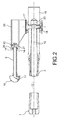
figure 2 shows the same view for the open position of the switch ; -
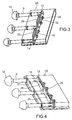
figure 3 particularly shows the inside of the compression system during a closing operation with open valves; and -
figure 4 shows the compression system again, but in an opening operation with closed valves. -
Figures 1 and2 partly illustrate an earthing switch comprising at least one pair of contacts comprising a fixed contact 1 and amobile contact 2, a front end of which can penetrate into the fixed contact 1. - The
mobile contact 2 is reversibly moved in a movement direction X-X (figure 1 ). The invention can be implemented independently on the number, kind and layout of contact pairs. For instance, the switch can be three-phase and the fixed and mobile contacts are aligned in straight rows perpendicular to the movement direction X-X. - The arrangement also comprises
blowpipes 9 located aside the pairs of fixed contacts 1 andmobile contacts 2. Front ends of theblowpipes 9 are equipped withnozzles 10. - The figures show that the
blowpipes 9 are straight, continuously hollow tubes, and thenozzles 10 are provided with a curved orelbowed drilling 11 that is directed towardsplaces 12 at which themobile contacts 2 separate from the fixed contact 1 and electric arcs will thus be present. Theblowpipes 9 are in the same number as the pairs of fixed and mobile contacts, are also arranged in a straight row and extend at a short distance above respective ones of the mobile contacts. Rear ends of theblowpipes 9 are connected to apiston 13 which is common to all theblowpipes 9, as illustrated byfigures 3 and 4 . The walls of theblowpipes 9 have openings 14 just before thepiston 13. - The
mobile contacts 2 slide in mobile contact tulips 15. The mobile contact tulips 15 are supported bytubular contact units 16 in the extension of themobile contacts 2. Acarriage 17 is supported by thecontact units 16 and slides on them. It comprisesaxes 18 which are articulated to rear parts of themobile contacts 2 and extend through thecontact units 16 throughlongitudinal slots 19 machined at the upper and lower surfaces of thecontact units 16. The switch operation consists in movements of thecarriage 17, displacing theaxes 18 between opposite ends of theslots 19 and themobile contacts 2 between the closed position of the contacts offigure 1 , in which themobile contacts 2 extend in thefront cavity 6, and the open position offigure 2 , in which themobile contacts 2 are completely retracted into the mobile contact tulips 15 andcentral bores 20 of thecontact units 16. Thecarriage 17 is displaced by a driving mechanism (not shown). - An enclosure in the shape of a
compression cylinder 25 is fastened to thecarriage 17 and displaced with it. It comprisesopenings 26 at the front face, through which theblowpipes 9 extend. Thepiston 13 is contained in thecompression cylinder 25. Thepiston 13 has an elongated rectangular shape, and the compression cylinder 25 a similarly elongated rectangular cross-section, so that they extend over the entire width of the row of mobile contacts but with a reduced height and can thus be accommodated easily in usual housings. Seals are provided at theopenings 26 and around thepiston 13 so that acompression chamber 27 defined by thecompression cylinder 25 and thepiston 13 generally communicates with the outside only through thenozzles 10. However,valves 28 are present on thepiston 13. They are generally closed by sets ofcompression springs 29, but are able to openslots 32, and establish a supplementary communication of thecompression chamber 27 with the outside, when a threshold of negative pressure is reached in thecompression chamber 27. - When the switch must open, the
carriage 17 is slid rearwards, themobile contacts 2 separate from the fixed contact tulips 1, and an electric arc appears between them at theseparation places 12. Thecompression cylinder 25 is slid on theblowpipes 9, and thecompression chamber 27 shrinks. The gas contained therein is compressed and flows outside at thenozzles 10, which deflect it towards theseparation places 12. The flows remain concentrated in thin beams directed precisely by thenozzles 10. Most of the blast energy therefore contributes to the arc extinction, in contrast with known devices in which the gas flow would be spread in thefront cavity 6 comprising the contacts so that the overall efficiency would be lower. Thevalves 28 remain closed. - And when the switch returns to the closed state, a reverse movement is made, and the
compression chamber 27 expands. A negative pressure buildup appears inside so that thevalves 28 open by uncoveringslots 32 punched through thepiston 13 for facilitating a gas ingress into thecompression chamber 27 until the pressure has increased at a degree allowing the springs sets 29 to bring thevalves 28 back on thepiston 13. - An originality of the invention is that the
piston 13 is stationary but the enclosure surrounding it -the compression cylinder 25- is mobile, in contrast to known devices in which a piston depends on the mobile contacts and the enclosure in which the piston slides is a part of the housing or another stationary structure. The inventive arrangement enables a compact layout in which thepiston 13 andcompression cylinder 25 are not a longitudinal extension of the mobile contacts but are located aside them. The driving mechanism is simple and lightweight, thecompression cylinder 25 and the mobile contacts being moved together by the same mechanism (the carriage 17). The piston rods -the blowpipes 9- can be made up with bores for channeling the gas flow and directing it accurately towards the even places -the separation places 12-where it is needed. Also, the pressure variations in thecompression chamber 27 during the swift connecting and disconnecting movements develop opposing forces that dampen these movements at the end of their respective stroke. - The
separation place 12 to which the gas flow is directed is not necessarily adjacent to the fixed contacts as in these drawings, but can be present at any location between the fixed contacts and the mobile contacts at the open position, in which the arc could be present. - While the detailed description concerned an earthing switch, the invention could be implemented in other kinds of electric switches.
- There is no condition on the gas filling the housing, which may be an insulating gas like SF6 or not.
Claims (8)
- An electric switch comprising : at least one fixed contact (1) ; at least one mobile contact (2) sliding in front of the fixed contact (1) in a movement direction between a closed position at which it is joined with the fixed contact and an open position at which it is separated from the fixed contact ; characterised in that it comprises : at least one fixed blowpipe (9) parallel to the movement direction, the blowpipe comprising a nozzle (10) at a front end, the nozzle being directed towards a place (12) at which the mobile contact separates from the fixed contact, and a piston (13) at a rear end ; a mobile enclosure (25) connected to the mobile contact (2) and sliding around the blowpipe (9) and around the piston (13), a compression chamber (27), which communicates with the nozzle (10), being defined by the enclosure, the piston and the blowpipe.
- An electric switch according to claim 1, characterised in that the compression chamber (27) is provided with a valve (28) that opens at a negative pressure of less than 1 bar inside the compression chamber.
- An electric switch according to claim 2, characterised in that the valve is provided on the piston.
- An electric switch according to any of claims 1 to 3, characterised in that the piston (13) has an elongated shape, and the enclosure (25) has a corresponding elongated cross-section.
- An electric switch according to any of claims 1 to 4, characterised in that it comprises a plurality of the fixed contacts and the mobile contacts, the mobile contacts being mobile together, and a plurality of the blowpipes, each of a blowpipes being associated to a respective one of the fixed contacts and of the mobile contacts, but the piston (13) is single and common to all the blowpipes (9), and the enclosure (25) is single too.
- An electric switch according to claims 4 and 5, characterised in that the blowpipes are arranged in a row along the piston, and the fixed contacts and the mobile contacts are arranged in rows parallel to said row of blowpipes.
- An electric switch according to any of claims 1 to 6, characterised in that the enclosure is fastened to a carriage (17) that also displaces the mobile contact.
- An electric switch according to any of claims 1 to 7, characterised in that the enclosure and the blowpipe are both arranged with overlaps with the mobile contact along the movement direction.
Priority Applications (1)
| Application Number | Priority Date | Filing Date | Title |
|---|---|---|---|
| EP16179999.4A EP3273463B1 (en) | 2016-07-18 | 2016-07-18 | Electric switch provided with an arc-blasting unit |
Applications Claiming Priority (1)
| Application Number | Priority Date | Filing Date | Title |
|---|---|---|---|
| EP16179999.4A EP3273463B1 (en) | 2016-07-18 | 2016-07-18 | Electric switch provided with an arc-blasting unit |
Publications (2)
| Publication Number | Publication Date |
|---|---|
| EP3273463A1 true EP3273463A1 (en) | 2018-01-24 |
| EP3273463B1 EP3273463B1 (en) | 2019-08-28 |
Family
ID=56418463
Family Applications (1)
| Application Number | Title | Priority Date | Filing Date |
|---|---|---|---|
| EP16179999.4A Active EP3273463B1 (en) | 2016-07-18 | 2016-07-18 | Electric switch provided with an arc-blasting unit |
Country Status (1)
| Country | Link |
|---|---|
| EP (1) | EP3273463B1 (en) |
Citations (4)
| Publication number | Priority date | Publication date | Assignee | Title |
|---|---|---|---|---|
| US2284840A (en) * | 1934-03-08 | 1942-06-02 | Gen Electric | Fluid blast circuit breaker |
| EP0503223A2 (en) * | 1991-03-13 | 1992-09-16 | Hitachi, Ltd. | Puffer-type gas circuit breaker |
| EP0744759A1 (en) * | 1995-05-24 | 1996-11-27 | Siemens Aktiengesellschaft | H.T. circuit breaker with a fixed heating chamber |
| US20100193474A1 (en) * | 2008-02-05 | 2010-08-05 | Rostron Joseph R | Limited flash-over electric power switch |
-
2016
- 2016-07-18 EP EP16179999.4A patent/EP3273463B1/en active Active
Patent Citations (4)
| Publication number | Priority date | Publication date | Assignee | Title |
|---|---|---|---|---|
| US2284840A (en) * | 1934-03-08 | 1942-06-02 | Gen Electric | Fluid blast circuit breaker |
| EP0503223A2 (en) * | 1991-03-13 | 1992-09-16 | Hitachi, Ltd. | Puffer-type gas circuit breaker |
| EP0744759A1 (en) * | 1995-05-24 | 1996-11-27 | Siemens Aktiengesellschaft | H.T. circuit breaker with a fixed heating chamber |
| US20100193474A1 (en) * | 2008-02-05 | 2010-08-05 | Rostron Joseph R | Limited flash-over electric power switch |
Also Published As
| Publication number | Publication date |
|---|---|
| EP3273463B1 (en) | 2019-08-28 |
Similar Documents
| Publication | Publication Date | Title |
|---|---|---|
| US8030590B2 (en) | Gas-circuit breaker | |
| EP3149757B1 (en) | High voltage puffer breaker and a circuit breaker unit comprising such a puffer breaker | |
| US10984973B2 (en) | Electric switch provided with an arc-blasting unit | |
| CA1042493A (en) | High voltage gas blast circuit interrupter | |
| US10964498B2 (en) | Gas-insulated low- or medium-voltage load break switch | |
| US20010025827A1 (en) | Power breaker | |
| KR101919125B1 (en) | Gas insulated switch device of high voltage distributer | |
| US12002639B2 (en) | Gas shut-off switch | |
| EP3273463B1 (en) | Electric switch provided with an arc-blasting unit | |
| JP2016173900A (en) | Puffer type gas circuit breaker | |
| KR100402234B1 (en) | Bidirectional operation type gas circuit breaker | |
| US2913559A (en) | Fluid-blast circuit interrupter | |
| JP5218449B2 (en) | Gas circuit breaker | |
| US5587571A (en) | Combined-action puffer circuit-breaker | |
| GB516529A (en) | Improvements in or relating to electric circuit-breaking devices of the gas-blast type | |
| US3686453A (en) | Gas-blast circuit breaker | |
| US2365134A (en) | Electric circuit breaker of the gas-blast type | |
| US3221129A (en) | Gas-blast circuit breaker of the recirculating gas type | |
| US5084600A (en) | Gas-blast load-break switch | |
| US3291949A (en) | Fluid-blast circuit interrupters having improved arc splitter structure | |
| JP6915077B2 (en) | Gas circuit breaker | |
| US4354073A (en) | Electric gas blast circuit breaker | |
| US12609258B2 (en) | Two-electric-pole circuit breaker actuated by a common pyrotechnic device | |
| JPH04280016A (en) | Intermediate voltage circuit breaker | |
| US20150069018A1 (en) | Circuit breaker with compactable contact structure |
Legal Events
| Date | Code | Title | Description |
|---|---|---|---|
| PUAI | Public reference made under article 153(3) epc to a published international application that has entered the european phase |
Free format text: ORIGINAL CODE: 0009012 |
|
| STAA | Information on the status of an ep patent application or granted ep patent |
Free format text: STATUS: THE APPLICATION HAS BEEN PUBLISHED |
|
| AK | Designated contracting states |
Kind code of ref document: A1 Designated state(s): AL AT BE BG CH CY CZ DE DK EE ES FI FR GB GR HR HU IE IS IT LI LT LU LV MC MK MT NL NO PL PT RO RS SE SI SK SM TR |
|
| AX | Request for extension of the european patent |
Extension state: BA ME |
|
| STAA | Information on the status of an ep patent application or granted ep patent |
Free format text: STATUS: REQUEST FOR EXAMINATION WAS MADE |
|
| 17P | Request for examination filed |
Effective date: 20180724 |
|
| RBV | Designated contracting states (corrected) |
Designated state(s): AL AT BE BG CH CY CZ DE DK EE ES FI FR GB GR HR HU IE IS IT LI LT LU LV MC MK MT NL NO PL PT RO RS SE SI SK SM TR |
|
| GRAP | Despatch of communication of intention to grant a patent |
Free format text: ORIGINAL CODE: EPIDOSNIGR1 |
|
| STAA | Information on the status of an ep patent application or granted ep patent |
Free format text: STATUS: GRANT OF PATENT IS INTENDED |
|
| INTG | Intention to grant announced |
Effective date: 20190206 |
|
| GRAS | Grant fee paid |
Free format text: ORIGINAL CODE: EPIDOSNIGR3 |
|
| GRAA | (expected) grant |
Free format text: ORIGINAL CODE: 0009210 |
|
| STAA | Information on the status of an ep patent application or granted ep patent |
Free format text: STATUS: THE PATENT HAS BEEN GRANTED |
|
| AK | Designated contracting states |
Kind code of ref document: B1 Designated state(s): AL AT BE BG CH CY CZ DE DK EE ES FI FR GB GR HR HU IE IS IT LI LT LU LV MC MK MT NL NO PL PT RO RS SE SI SK SM TR |
|
| REG | Reference to a national code |
Ref country code: GB Ref legal event code: FG4D |
|
| REG | Reference to a national code |
Ref country code: CH Ref legal event code: EP |
|
| REG | Reference to a national code |
Ref country code: CH Ref legal event code: NV Representative=s name: VALIPAT S.A. C/O BOVARD SA NEUCHATEL, CH |
|
| REG | Reference to a national code |
Ref country code: AT Ref legal event code: REF Ref document number: 1173423 Country of ref document: AT Kind code of ref document: T Effective date: 20190915 |
|
| REG | Reference to a national code |
Ref country code: IE Ref legal event code: FG4D |
|
| REG | Reference to a national code |
Ref country code: DE Ref legal event code: R096 Ref document number: 602016019284 Country of ref document: DE |
|
| REG | Reference to a national code |
Ref country code: SE Ref legal event code: TRGR |
|
| REG | Reference to a national code |
Ref country code: NL Ref legal event code: MP Effective date: 20190828 |
|
| REG | Reference to a national code |
Ref country code: LT Ref legal event code: MG4D |
|
| PG25 | Lapsed in a contracting state [announced via postgrant information from national office to epo] |
Ref country code: FI Free format text: LAPSE BECAUSE OF FAILURE TO SUBMIT A TRANSLATION OF THE DESCRIPTION OR TO PAY THE FEE WITHIN THE PRESCRIBED TIME-LIMIT Effective date: 20190828 Ref country code: PT Free format text: LAPSE BECAUSE OF FAILURE TO SUBMIT A TRANSLATION OF THE DESCRIPTION OR TO PAY THE FEE WITHIN THE PRESCRIBED TIME-LIMIT Effective date: 20191230 Ref country code: NL Free format text: LAPSE BECAUSE OF FAILURE TO SUBMIT A TRANSLATION OF THE DESCRIPTION OR TO PAY THE FEE WITHIN THE PRESCRIBED TIME-LIMIT Effective date: 20190828 Ref country code: NO Free format text: LAPSE BECAUSE OF FAILURE TO SUBMIT A TRANSLATION OF THE DESCRIPTION OR TO PAY THE FEE WITHIN THE PRESCRIBED TIME-LIMIT Effective date: 20191128 Ref country code: BG Free format text: LAPSE BECAUSE OF FAILURE TO SUBMIT A TRANSLATION OF THE DESCRIPTION OR TO PAY THE FEE WITHIN THE PRESCRIBED TIME-LIMIT Effective date: 20191128 Ref country code: LT Free format text: LAPSE BECAUSE OF FAILURE TO SUBMIT A TRANSLATION OF THE DESCRIPTION OR TO PAY THE FEE WITHIN THE PRESCRIBED TIME-LIMIT Effective date: 20190828 Ref country code: HR Free format text: LAPSE BECAUSE OF FAILURE TO SUBMIT A TRANSLATION OF THE DESCRIPTION OR TO PAY THE FEE WITHIN THE PRESCRIBED TIME-LIMIT Effective date: 20190828 |
|
| PG25 | Lapsed in a contracting state [announced via postgrant information from national office to epo] |
Ref country code: RS Free format text: LAPSE BECAUSE OF FAILURE TO SUBMIT A TRANSLATION OF THE DESCRIPTION OR TO PAY THE FEE WITHIN THE PRESCRIBED TIME-LIMIT Effective date: 20190828 Ref country code: IS Free format text: LAPSE BECAUSE OF FAILURE TO SUBMIT A TRANSLATION OF THE DESCRIPTION OR TO PAY THE FEE WITHIN THE PRESCRIBED TIME-LIMIT Effective date: 20191228 Ref country code: GR Free format text: LAPSE BECAUSE OF FAILURE TO SUBMIT A TRANSLATION OF THE DESCRIPTION OR TO PAY THE FEE WITHIN THE PRESCRIBED TIME-LIMIT Effective date: 20191129 Ref country code: AL Free format text: LAPSE BECAUSE OF FAILURE TO SUBMIT A TRANSLATION OF THE DESCRIPTION OR TO PAY THE FEE WITHIN THE PRESCRIBED TIME-LIMIT Effective date: 20190828 Ref country code: LV Free format text: LAPSE BECAUSE OF FAILURE TO SUBMIT A TRANSLATION OF THE DESCRIPTION OR TO PAY THE FEE WITHIN THE PRESCRIBED TIME-LIMIT Effective date: 20190828 Ref country code: ES Free format text: LAPSE BECAUSE OF FAILURE TO SUBMIT A TRANSLATION OF THE DESCRIPTION OR TO PAY THE FEE WITHIN THE PRESCRIBED TIME-LIMIT Effective date: 20190828 |
|
| REG | Reference to a national code |
Ref country code: AT Ref legal event code: MK05 Ref document number: 1173423 Country of ref document: AT Kind code of ref document: T Effective date: 20190828 |
|
| PG25 | Lapsed in a contracting state [announced via postgrant information from national office to epo] |
Ref country code: TR Free format text: LAPSE BECAUSE OF FAILURE TO SUBMIT A TRANSLATION OF THE DESCRIPTION OR TO PAY THE FEE WITHIN THE PRESCRIBED TIME-LIMIT Effective date: 20190828 |
|
| PG25 | Lapsed in a contracting state [announced via postgrant information from national office to epo] |
Ref country code: IT Free format text: LAPSE BECAUSE OF FAILURE TO SUBMIT A TRANSLATION OF THE DESCRIPTION OR TO PAY THE FEE WITHIN THE PRESCRIBED TIME-LIMIT Effective date: 20190828 Ref country code: PL Free format text: LAPSE BECAUSE OF FAILURE TO SUBMIT A TRANSLATION OF THE DESCRIPTION OR TO PAY THE FEE WITHIN THE PRESCRIBED TIME-LIMIT Effective date: 20190828 Ref country code: EE Free format text: LAPSE BECAUSE OF FAILURE TO SUBMIT A TRANSLATION OF THE DESCRIPTION OR TO PAY THE FEE WITHIN THE PRESCRIBED TIME-LIMIT Effective date: 20190828 Ref country code: DK Free format text: LAPSE BECAUSE OF FAILURE TO SUBMIT A TRANSLATION OF THE DESCRIPTION OR TO PAY THE FEE WITHIN THE PRESCRIBED TIME-LIMIT Effective date: 20190828 Ref country code: AT Free format text: LAPSE BECAUSE OF FAILURE TO SUBMIT A TRANSLATION OF THE DESCRIPTION OR TO PAY THE FEE WITHIN THE PRESCRIBED TIME-LIMIT Effective date: 20190828 Ref country code: RO Free format text: LAPSE BECAUSE OF FAILURE TO SUBMIT A TRANSLATION OF THE DESCRIPTION OR TO PAY THE FEE WITHIN THE PRESCRIBED TIME-LIMIT Effective date: 20190828 |
|
| PG25 | Lapsed in a contracting state [announced via postgrant information from national office to epo] |
Ref country code: CZ Free format text: LAPSE BECAUSE OF FAILURE TO SUBMIT A TRANSLATION OF THE DESCRIPTION OR TO PAY THE FEE WITHIN THE PRESCRIBED TIME-LIMIT Effective date: 20190828 Ref country code: SK Free format text: LAPSE BECAUSE OF FAILURE TO SUBMIT A TRANSLATION OF THE DESCRIPTION OR TO PAY THE FEE WITHIN THE PRESCRIBED TIME-LIMIT Effective date: 20190828 Ref country code: IS Free format text: LAPSE BECAUSE OF FAILURE TO SUBMIT A TRANSLATION OF THE DESCRIPTION OR TO PAY THE FEE WITHIN THE PRESCRIBED TIME-LIMIT Effective date: 20200224 Ref country code: SM Free format text: LAPSE BECAUSE OF FAILURE TO SUBMIT A TRANSLATION OF THE DESCRIPTION OR TO PAY THE FEE WITHIN THE PRESCRIBED TIME-LIMIT Effective date: 20190828 |
|
| REG | Reference to a national code |
Ref country code: DE Ref legal event code: R097 Ref document number: 602016019284 Country of ref document: DE |
|
| PLBE | No opposition filed within time limit |
Free format text: ORIGINAL CODE: 0009261 |
|
| STAA | Information on the status of an ep patent application or granted ep patent |
Free format text: STATUS: NO OPPOSITION FILED WITHIN TIME LIMIT |
|
| PG2D | Information on lapse in contracting state deleted |
Ref country code: IS |
|
| 26N | No opposition filed |
Effective date: 20200603 |
|
| PG25 | Lapsed in a contracting state [announced via postgrant information from national office to epo] |
Ref country code: SI Free format text: LAPSE BECAUSE OF FAILURE TO SUBMIT A TRANSLATION OF THE DESCRIPTION OR TO PAY THE FEE WITHIN THE PRESCRIBED TIME-LIMIT Effective date: 20190828 |
|
| PG25 | Lapsed in a contracting state [announced via postgrant information from national office to epo] |
Ref country code: MC Free format text: LAPSE BECAUSE OF FAILURE TO SUBMIT A TRANSLATION OF THE DESCRIPTION OR TO PAY THE FEE WITHIN THE PRESCRIBED TIME-LIMIT Effective date: 20190828 |
|
| GBPC | Gb: european patent ceased through non-payment of renewal fee |
Effective date: 20200718 |
|
| REG | Reference to a national code |
Ref country code: BE Ref legal event code: MM Effective date: 20200731 |
|
| PG25 | Lapsed in a contracting state [announced via postgrant information from national office to epo] |
Ref country code: GB Free format text: LAPSE BECAUSE OF NON-PAYMENT OF DUE FEES Effective date: 20200718 Ref country code: LU Free format text: LAPSE BECAUSE OF NON-PAYMENT OF DUE FEES Effective date: 20200718 |
|
| PG25 | Lapsed in a contracting state [announced via postgrant information from national office to epo] |
Ref country code: BE Free format text: LAPSE BECAUSE OF NON-PAYMENT OF DUE FEES Effective date: 20200731 |
|
| PG25 | Lapsed in a contracting state [announced via postgrant information from national office to epo] |
Ref country code: IE Free format text: LAPSE BECAUSE OF NON-PAYMENT OF DUE FEES Effective date: 20200718 |
|
| PG25 | Lapsed in a contracting state [announced via postgrant information from national office to epo] |
Ref country code: MT Free format text: LAPSE BECAUSE OF FAILURE TO SUBMIT A TRANSLATION OF THE DESCRIPTION OR TO PAY THE FEE WITHIN THE PRESCRIBED TIME-LIMIT Effective date: 20190828 Ref country code: CY Free format text: LAPSE BECAUSE OF FAILURE TO SUBMIT A TRANSLATION OF THE DESCRIPTION OR TO PAY THE FEE WITHIN THE PRESCRIBED TIME-LIMIT Effective date: 20190828 |
|
| PG25 | Lapsed in a contracting state [announced via postgrant information from national office to epo] |
Ref country code: MK Free format text: LAPSE BECAUSE OF FAILURE TO SUBMIT A TRANSLATION OF THE DESCRIPTION OR TO PAY THE FEE WITHIN THE PRESCRIBED TIME-LIMIT Effective date: 20190828 |
|
| P01 | Opt-out of the competence of the unified patent court (upc) registered |
Effective date: 20230522 |
|
| PGFP | Annual fee paid to national office [announced via postgrant information from national office to epo] |
Ref country code: FR Payment date: 20250620 Year of fee payment: 10 |
|
| PGFP | Annual fee paid to national office [announced via postgrant information from national office to epo] |
Ref country code: SE Payment date: 20250619 Year of fee payment: 10 |
|
| PGFP | Annual fee paid to national office [announced via postgrant information from national office to epo] |
Ref country code: DE Payment date: 20250620 Year of fee payment: 10 |
|
| PGFP | Annual fee paid to national office [announced via postgrant information from national office to epo] |
Ref country code: CH Payment date: 20250801 Year of fee payment: 10 |