EP3273412A1 - Three-dimensional modelling method and device - Google Patents
Three-dimensional modelling method and device Download PDFInfo
- Publication number
- EP3273412A1 EP3273412A1 EP16764182.8A EP16764182A EP3273412A1 EP 3273412 A1 EP3273412 A1 EP 3273412A1 EP 16764182 A EP16764182 A EP 16764182A EP 3273412 A1 EP3273412 A1 EP 3273412A1
- Authority
- EP
- European Patent Office
- Prior art keywords
- feature points
- image
- grid
- similarities
- matching
- Prior art date
- Legal status (The legal status is an assumption and is not a legal conclusion. Google has not performed a legal analysis and makes no representation as to the accuracy of the status listed.)
- Granted
Links
Images




Classifications
-
- G—PHYSICS
- G06—COMPUTING OR CALCULATING; COUNTING
- G06T—IMAGE DATA PROCESSING OR GENERATION, IN GENERAL
- G06T17/00—Three-dimensional [3D] modelling for computer graphics
- G06T17/20—Finite element generation, e.g. wire-frame surface description, tesselation
-
- G—PHYSICS
- G06—COMPUTING OR CALCULATING; COUNTING
- G06T—IMAGE DATA PROCESSING OR GENERATION, IN GENERAL
- G06T17/00—Three-dimensional [3D] modelling for computer graphics
-
- G—PHYSICS
- G06—COMPUTING OR CALCULATING; COUNTING
- G06T—IMAGE DATA PROCESSING OR GENERATION, IN GENERAL
- G06T15/00—Three-dimensional [3D] image rendering
- G06T15/10—Geometric effects
- G06T15/20—Perspective computation
- G06T15/205—Image-based rendering
-
- G—PHYSICS
- G06—COMPUTING OR CALCULATING; COUNTING
- G06T—IMAGE DATA PROCESSING OR GENERATION, IN GENERAL
- G06T7/00—Image analysis
- G06T7/10—Segmentation; Edge detection
- G06T7/11—Region-based segmentation
-
- G—PHYSICS
- G06—COMPUTING OR CALCULATING; COUNTING
- G06T—IMAGE DATA PROCESSING OR GENERATION, IN GENERAL
- G06T7/00—Image analysis
- G06T7/50—Depth or shape recovery
- G06T7/55—Depth or shape recovery from multiple images
-
- G—PHYSICS
- G06—COMPUTING OR CALCULATING; COUNTING
- G06V—IMAGE OR VIDEO RECOGNITION OR UNDERSTANDING
- G06V40/00—Recognition of biometric, human-related or animal-related patterns in image or video data
- G06V40/10—Human or animal bodies, e.g. vehicle occupants or pedestrians; Body parts, e.g. hands
- G06V40/16—Human faces, e.g. facial parts, sketches or expressions
-
- G—PHYSICS
- G06—COMPUTING OR CALCULATING; COUNTING
- G06T—IMAGE DATA PROCESSING OR GENERATION, IN GENERAL
- G06T2207/00—Indexing scheme for image analysis or image enhancement
- G06T2207/30—Subject of image; Context of image processing
- G06T2207/30196—Human being; Person
- G06T2207/30201—Face
Definitions
- the present application relates to the technical field of computers and, in particular to a three-dimensional modeling method and apparatus.
- the accuracy of three-dimensional modeling may possibly be reduced.
- the embodiments of the present application provide a three-dimensional modeling method and apparatus, in order to solve the problem of three-dimensional modeling in the prior art requiring a great amount of calculations which are not easily implemented on a mobile device, such as a mobile phone.
- a three-dimensional modeling method is provided in an embodiment of the present application, comprising:
- a three-dimensional modeling method is provided in another embodiment of the present application, comprising:
- a three-dimensional modeling apparatus comprising:
- a three-dimensional modeling apparatus is provided in another embodiment of the present application, comprising:
- the embodiments of the present application provide a three-dimensional modeling method and apparatus.
- the method involves: capturing images in at least two different directions of an object, acquiring feature points on one of the images, and determining corresponding matching feature points on the images in the remaining directions, so as to calculate depth values of the various feature points; and performing weighted calculation on the depth values of the various feature points with similarities between the feature points and the matching feature points, and performing three-dimensional modeling on the object by utilizing the depth values of the various feature points after being subjected to the weighted calculation, so that the method effectively reduces the amount of calculation of three-dimensional modeling, is easily implemented on a mobile device, such as a mobile phone, and has a relatively high accuracy.
- Fig. 1 is a process of three-dimensional modeling provided in an embodiment of the present application, specifically comprising the steps of:
- the object comprises various objects having a three-dimensional construction, e.g., a human face.
- the first image and the second image may have specific differences in terms of angle of elevation, angle of deflection and angle of rotation from each other.
- Both the first image and the second image contain RGB channels (i.e., the first image and the second image are color images), and the pixels of both images are above 392 ⁇ 440.
- the first image and the second image may also be grayscale maps.
- the angle of elevation, angle of deflection and angle of rotation as described in the present application are explained.
- the X axis is defined as a horizontal axis of the front face of the human face
- the Y axis is defined as a vertical axis of the front face of the human face
- the Z axis is perpendicular to the X axis and the Y axis
- the Z axis indicates the depth of features on the human face.
- the angle ⁇ of elevation is an angle for the human face to rotate clockwise from the Y axis to the Z axis on the YZ plane; as shown in Fig. 6 , the angle ⁇ of deflection is an angle for the human face to rotate anti-clockwise from the X axis to the Z axis on the XZ plane; and as shown in Fig. 7 , the angle ⁇ of rotation is an angle for the human face to rotate anti-clockwise from the X axis to the Y axis on the XY plane.
- the acquisition of the feature points may use the method of edge detection, so as to acquire points with significant changes in brightness in the first image.
- image edge detection may greatly reduce the amount of processing of data, while retaining important structural attributes of the image, such as: discontinuity in depth, discontinuity in a surface direction, a material property change, a scenario illumination change.
- step S12 the steps of acquiring a plurality of feature points on the first image in step S12 are introduced, comprising:
- the acquisition of the initial feature points uses the method of edge detection, and these initial feature points reflect feature profiles of edges, five sense organs on the human face.
- grid cells in the first grid are defined as squares, and of course the grid cells of the first grid may also be pre-defined as a plurality of shapes such as a triangle or a regular hexagon according to requirements.
- the several initial feature points on the first image may respectively fall into various grid cells of the first grid. It needs to be noted that in practical application scenarios, for example, in a mobile phone, the matching of the first image and the first grid is accomplished by operation processing of a data processor within the mobile phone, rather than being necessarily fed back visually.
- the standard is to ensure that the numbers of initial feature points retained in the grid cells of the first grid are equal to screen the several initial feature points
- other screening standards may also be used, for example: setting that the difference between numbers of initial feature points in various grid cells is not greater than a pre-determined threshold.
- the specific screening process for the initial feature points is as follows: first, calculating the distances from the several initial feature points to centers of the grid cells of the first grid where these points are located, and then determining, in the grid cells of the first grid, an initial feature point closest to the center of the grid cell where this point is located as the feature point.
- the centers of these grid cells are determined as feature points therein.
- the average values of the coordinates of the initial feature points of the various grid cells may also be solved, and the points corresponding to the obtained average coordinate values are taken as feature points retained in the corresponding grid cells in the first grid.
- step 13 the objective of step 13 is to search for the position where the tip of the nose is located (i.e., the coordinates of a matching feature point A') on the second image, and then establish a correlation between a plurality of feature points and matching feature points on the first image and the second image according to this method.
- step S13 the specific steps of determining matching feature points in step S13 are introduced, comprising:
- the direction information about the first image and the second image may be determined by a plurality of means. Taking shooting a human face by a mobile phone as an example:
- direction information about the first image and the second image may be determined, for example, by means of a posture measurement algorithm.
- the rotation of the human face is determined based on an assumed rotation center C
- the coordinates C X , C Y and Cz of the rotation center can be roughly estimated, while the distance r from the rotation center C to the center of the two eyes on the human face can be used to measure the angle ⁇ of elevation, angle ⁇ of deflection and angle ⁇ of rotation described above.
- the grid cells of the second grid are used as the grid cells of the second grid.
- the area of the grid cells of the second grid is set as being smaller than that of the grid cells of the first grid (that is: in the first grid and the second grid of the same area, more grid cells relative to the first grid are divided in the second grid cells), so as to improve the accuracy of determining the matching feature points in the following step.
- step S14 the specific steps of calculating similarities between the feature points and the matching feature points in step S14 are introduced, comprising:
- step S141 and step S142 refer to color values of pixels in three channels, R, G and B.
- the similarities between the feature points and the matching feature points are determined according to the values of average color value errors obtained through calculation, and the greater the average color value error, the lower the similarity between a feature point and a matching feature point.
- the feature points can be screened by utilizing the similarities between the feature points and the matching feature points. Specifically:
- the depth value of a feature point is obtained by synthesizing the depths of the matching feature point at an angle of elevation, angle of deflection and angle of rotation, and performing calculation in combination with the depth values at these different angles may enable the angles to have a greater influence, and improve the accuracy of the depth value calculation result.
- the calculation formula of the depth value Z is obtained by synthesizing Z ⁇ , Z ⁇ and Z ⁇ as follows:
- Z Z ⁇ sin ⁇ sin ⁇ + sin ⁇ + sin ⁇ + Z ⁇ sin ⁇ sin ⁇ + sin ⁇ + sin ⁇ + sin ⁇ + sin ⁇ + sin ⁇ + sin ⁇ + sin ⁇ + sin ⁇ + sin ⁇ + sin ⁇ + sin ⁇ + sin ⁇ + sin ⁇ .
- weighted depth value depth value Z ⁇ ( sum of the average color value errors of all the feature points except the feature points to be subjected to the weighted calculation / sum of the average color value errors of all the feature points ) .
- the three-dimensional modeling adopts a triangular grid, and vertices of the triangular grid are respective feature points.
- a method e.g., polygon modeling, may also be used.
- Fig. 11 is a process of three-dimensional modeling provided in another embodiment of the present application, specifically comprising the steps of:
- a first image of the object in a reference direction and a second image, a third image and a fourth image in three directions deviating from the reference direction are captured.
- the first image, second image, third image and fourth image are respectively a front face image, a front face elevated image, a front face left-inclined image and a front face right-inclined image of the human face.
- matching feature points corresponding to the feature points captured on the front face image of the human face can all be substantially found on at least one of the front face elevated image, front face left-inclined image and front face right-inclined image, and therefore the calculation process for the depth value of each feature point on the front face image of the human face has synthesized the factor of angles, thereby ensuring that the depth value obtained through calculation has a higher accuracy.
- the three-dimensional modeling method in the present application is described taking capturing four images as an example, but this is not a limitation, and according to specific environments of application and the difference of precision requirements, the number of captured images may also be adjusted adaptively.
- this embodiment does not involve improvements for other steps of the last embodiment, those steps will not be described otherwise herein, and the method and apparatus described in detail in the last embodiment may both be applied in this embodiment in its entirety.
- Fig. 13 is a schematic diagram of modules of a three-dimensional modeling apparatus provided in an embodiment of the present application, specifically comprising:
- the feature detection module 32 is specifically used for: acquiring several initial feature points on the first image, matching the first image with a pre-set first grid, and screening the several initial feature points until the numbers of initial feature points retained in grid cells of the first grid are equal, and determining them as the feature points.
- the feature detection module 32 comprises a calculation unit 321, and the calculation unit 321 is specifically used for: calculating distances from the several initial feature points to centers of the grid cells of the first grid where these points are located; and the feature detection module 32 is specifically used for determining, in the grid cells of the first grid, an initial feature point closest to the center of the grid cell where this point is located as the feature point.
- the feature detection module 32 is further used for: when a grid cell of the first grid is devoid of the initial feature points, determining the center of the grid cell as a feature point within the grid cell.
- the matching module 33 is specifically used for: determining, according to direction information about the first image and the second image, pre-matching feature points on the second image that correspond to the plurality of feature points, matching the second image with a pre-set second grid, and determining centers of grid cells of the second grid where the pre-matching feature points are located as the corresponding matching feature points.
- the calculation module 34 is specifically used for: acquiring color values of all pixels within the grid cells of the first grid where the plurality of feature points are located, acquiring color values of all pixels within the grid cells of the second grid where the plurality of matching feature points are located, and respectively calculating average color value errors between all the pixels within the grid cells of the first grid where the plurality of feature points are located and those within the grid cells of the second grid where the corresponding matching feature points are located, and determining, according to the average color value errors, the similarities between the plurality of feature points and the corresponding matching feature points.
- the area of the grid cells of the second grid is smaller than the area of the grid cells of the first grid.
- the apparatus further comprises a screening module 35 for, prior to performing the weighted calculation on the depth values of the plurality of feature points, screening the plurality of feature points according to the similarities between the plurality of feature points and the corresponding matching feature points.
- the screening module 35 is specifically used for: first determining a discard threshold according to the similarities between the plurality of feature points and the corresponding matching feature points, and then screening out, from the plurality of feature points, feature points of which similarities with the corresponding matching feature points are greater than the discard threshold.
- the model generation module 36 performs three-dimensional modeling on the object by adopting a triangular grid.
- the apparatus comprising:
- the image capture module 31 is specifically used for: capturing a first image of the object in a reference direction and a second image, a third image and a fourth image in three directions deviating from the reference direction.
- the object comprises: a human face.
- the first image, second image, third image and fourth image are respectively a front face image, a front face elevated image, a front face left-inclined image and a front face right-inclined image of the human face.
- the embodiments of the present application provide a three-dimensional modeling method and apparatus.
- the method involves: capturing images in at least two different directions of an object, acquiring feature points on one of the images, and determining corresponding matching feature points on the images in the remaining directions, so as to calculate depth values of the various feature points; and performing weighted calculation on the depth values of the various feature points with similarities between the feature points and the matching feature points, and performing three-dimensional modeling on the object by utilizing the depth values of the various feature points after being subjected to the weighted calculation, so that the method effectively reduces the amount of calculation of three-dimensional modeling, is easily implemented on a mobile device such as a mobile phone, and has a relatively high accuracy.
- the embodiments of the present invention may be provided as methods, systems, or computer program products. Therefore, the present invention may adopt hardware only embodiments, software only embodiments, or embodiments with a combination of software and hardware. Moreover, the present invention may adopt the form of a computer program product that is implemented on one or more computer-usable storage mediums (including but not limited to a disk memory, a CD-ROM, an optical memory, and the like) that include computer-usable program code.
- a computer-usable storage mediums including but not limited to a disk memory, a CD-ROM, an optical memory, and the like
- each flow and/or block in the flow charts and/or block diagrams and any combination of the flows and/or blocks in the flow charts and/or block diagrams may be implemented with computer program instructions.
- These computer program instructions may be provided to a processor of a general-purpose computer, a dedicated-purpose computer, an embedded processor or other programmable data processing devices to generate a machine, so that the instructions executed by the processor of a computer or other programmable data processing devices generate a means for implementing the functions specified in one or more flows of the flowcharts and/or one or more blocks of the block diagrams.
- These computer program instructions may also be stored in a computer-readable memory which may guide a computer or other programmable data processing devices to operate in a specific manner, so that the instructions stored in the computer-readable memory generate an article of manufacture including an instruction means which can implement the functions specified in one or more flows of the flowcharts and/or one or more blocks of the block diagrams.
- These computer program instructions may also be loaded in a computer or other programmable data processing devices, so that a series of operation steps are executed by the computer or other programmable devices to realize computer-implemented processing and thus the instructions executed by the computer or other programmable devices provide steps for implementing the functions specified in one or more flows of the flow charts and/or one or more blocks of the block diagrams.
- a computing device includes one or more processors (CPUs), an input/output interface, a network interface and a memory.
- the memory may include a non-permanent memory, a random access memory (RAM) and/or a non-volatile memory (such as a read-only memory (ROM) or flash memory (flash RAM)) and so on in computer-readable mediums.
- RAM random access memory
- non-volatile memory such as a read-only memory (ROM) or flash memory (flash RAM)
- ROM read-only memory
- flash RAM flash memory
- the computer-readable mediums comprise permanent and non-permanent, removable and non-removable media and may realize information storage with any method or technology.
- the information may be a computer-readable instruction, data structure, program module or other data.
- the examples of computer storage mediums include but are not limited to a phase change memory (PRAM), static random access memory (SRAM), dynamic random access memory (DRAM), other types of random access memories (RAMs), read-only memory (ROM), electrically erasable programmable read-only memory (EEPROM), flash memory or other memory technologies, compact disk read-only memory (CD-ROM), digital versatile disc (DVD) or other optical storage, magnetic cassette tape, magnetic tape and magnetic disk storage or other magnetic storage devices or any other non-transmission mediums, which can be used to store information that can be accessed by a computing device.
- the computer-readable mediums do not include transitory computer-readable media, such as modulated data signals and carriers.
- the embodiments of the present application may be provided as methods, systems or computer program products.
- the present application may adopt full hardware embodiments, full software embodiments, or embodiments which combine software and hardware.
- the present application may adopt the form of a computer program product that is implemented on one or more computer-usable storage mediums (including but not limited to a disk memory, a CD-ROM, an optical memory, and the like) that include computer usable program codes.
Landscapes
- Engineering & Computer Science (AREA)
- Physics & Mathematics (AREA)
- Theoretical Computer Science (AREA)
- General Physics & Mathematics (AREA)
- Geometry (AREA)
- Computer Graphics (AREA)
- Computer Vision & Pattern Recognition (AREA)
- Software Systems (AREA)
- Computing Systems (AREA)
- Health & Medical Sciences (AREA)
- General Health & Medical Sciences (AREA)
- Oral & Maxillofacial Surgery (AREA)
- Human Computer Interaction (AREA)
- Multimedia (AREA)
- Image Processing (AREA)
- Image Analysis (AREA)
Abstract
Description
- The present application claims priority of the Chinese Patent Application No.
201510117117.2, filed on 17 March 2015 - The present application relates to the technical field of computers and, in particular to a three-dimensional modeling method and apparatus.
- In the field of computer vision, three-dimensional modeling for an object based on 2D image data has been widely applied. Information included in a 2D image, such as light streams, shadows and texture, can all be used for determining the depth of an object, thereby constructing a three-dimensional model.
- However, the amount of calculation in acquiring a depth value by means of information, such as light streams, shadows and texture, is extremely large. Taking a mobile device such as a mobile phone as an example, a built-in processor has difficulty in performing real-time calculation on the information above, thereby limiting the application of some services or functions based on three-dimensional modeling on the mobile device such as a mobile phone.
- On the other hand, if the amount of processing of information is reduced to accommodate the computation capability of the processor of a mobile device, such as a mobile phone, the accuracy of three-dimensional modeling may possibly be reduced.
- The embodiments of the present application provide a three-dimensional modeling method and apparatus, in order to solve the problem of three-dimensional modeling in the prior art requiring a great amount of calculations which are not easily implemented on a mobile device, such as a mobile phone.
- A three-dimensional modeling method is provided in an embodiment of the present application, comprising:
- respectively capturing a first image in a first direction and a second image in a second direction of an object;
- acquiring a plurality of feature points on the first image;
- determining matching feature points on the second image that correspond to the plurality of feature points;
- calculating similarities between the plurality of feature points and the corresponding matching feature points, and depth values of the plurality of feature points;
- performing weighted calculation on the depth values of the plurality of feature points according to the similarities between the plurality of feature points and the corresponding matching feature points; and
- performing three-dimensional modeling on the object based on the depth values of the plurality of feature points after being subjected to the weighted calculation.
- A three-dimensional modeling method is provided in another embodiment of the present application, comprising:
- capturing images of an object in a plurality of directions;
- acquiring a plurality of feature points on one of the plurality of images;
- respectively determining matching feature points on the remaining images that correspond to the plurality of feature points;
- respectively calculating similarities between the plurality of feature points and the corresponding matching feature points on the remaining images and depth values of the matching feature points;
- calculating depth values of the plurality of feature points according to direction information about the plurality of images and the depth values of the matching feature points;
- performing weighted calculation on the depth values of the plurality of feature points according to the similarities between the plurality of feature points and the corresponding matching feature points on the remaining images; and
- performing three-dimensional modeling on the object based on the depth values of the plurality of feature points after being subjected to the weighted calculation.
- A three-dimensional modeling apparatus is provided in an embodiment of the present application, comprising:
- an image capture module for respectively capturing a first image in a first direction and a second image in a second direction of an object;
- a feature detection module for acquiring a plurality of feature points on the first image;
- a matching module for determining matching feature points on the second image that correspond to the plurality of feature points;
- a calculation module for calculating similarities between the plurality of feature points and the corresponding matching feature points and depth values of the plurality of feature points, and performing weighted calculation on the depth values of the plurality of feature points according to the similarities between the plurality of feature points and the corresponding matching feature points; and
- a model generation module for performing three-dimensional modeling on the object based on the depth values of the plurality of feature points after being subjected to the weighted calculation.
- A three-dimensional modeling apparatus is provided in another embodiment of the present application, comprising:
- an image capture module for capturing images of an object in a plurality of directions;
- a feature detection module for acquiring a plurality of feature points on one of the plurality of images;
- a matching module for respectively determining matching feature points on the remaining images that correspond to the plurality of feature points;
- a calculation module for respectively calculating similarities between the plurality of feature points and the corresponding matching feature points on the remaining images and depth values of the matching feature points, calculating depth values of the plurality of feature points according to direction information about the plurality of images and the depth values of the matching feature points, and performing weighted calculation on the depth values of the plurality of feature points according to the similarities between the plurality of feature points and the corresponding matching feature points on the remaining images; and
- a model generation module for performing three-dimensional modeling on the object based on the depth values of the plurality of feature points after being subjected to the weighted calculation.
- The embodiments of the present application provide a three-dimensional modeling method and apparatus. The method involves: capturing images in at least two different directions of an object, acquiring feature points on one of the images, and determining corresponding matching feature points on the images in the remaining directions, so as to calculate depth values of the various feature points; and performing weighted calculation on the depth values of the various feature points with similarities between the feature points and the matching feature points, and performing three-dimensional modeling on the object by utilizing the depth values of the various feature points after being subjected to the weighted calculation, so that the method effectively reduces the amount of calculation of three-dimensional modeling, is easily implemented on a mobile device, such as a mobile phone, and has a relatively high accuracy.
- The drawings described herein are used to provide further understanding of the present application, which constitute a part of the present application. The illustrative embodiments of the present application and the description thereof are used to explain the present application and do not constitute a limitation to the present application. In the drawings:
-
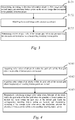
Fig. 1 is a schematic flow chart of three-dimensional modeling provided in an embodiment of the present application; -
Fig. 2 is a flow chart of acquiring feature points provided in an embodiment of the present application; -
Fig. 3 is a flow chart of determining matching feature points on a second image that correspond to feature points on a first image provided in an embodiment of the present application; -
Fig. 4 is a flow chart of calculating similarities between feature points and matching feature points provided in an embodiment of the present application; -
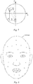
Fig. 5 is a schematic diagram of coordinates when a human face rotates by an angle α of elevation clockwise from the Y axis to the Z axis on a YZ plane provided in an embodiment of the present application; -
Fig. 6 is a schematic diagram of coordinates when a human face rotates by an angle β of deflection anti-clockwise from the X axis to the Z axis on an XZ plane provided in an embodiment of the present application; -
Fig. 7 is a schematic diagram of coordinates when a human face rotates by an angle γ of rotation anti-clockwise from the X axis to the Y axis on an XY plane provided in an embodiment of the present application; -
Fig. 8 is a schematic diagram of initial feature points acquired on a first image provided in an embodiment of the present application; -
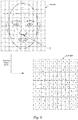
Fig. 9 is a schematic diagram of screening initial feature points utilizing a first grid provided in an embodiment of the present application; -
Fig. 10 is a schematic diagram of searching, on a second image, for a matching feature point A' corresponding to a feature point A on a first image provided in an embodiment of the present application; -
Fig. 11 is a schematic flow chart of three-dimensional modeling provided in another embodiment of the present application; -
Fig. 12 is a schematic diagram of a front face image, a front face elevated image, a front face left-inclined image and a front face right-inclined image of a human face captured utilizing a mobile phone provided in another embodiment of the present application; and -
Fig. 13 is a schematic diagram of modules of a three-dimensional modeling apparatus provided in an embodiment of the present application. - In order to make the object, technical solution and advantages of the present application more clear, the technical solution of the present application will be described clearly and completely in conjunction with particular embodiments of the present application and corresponding drawings hereinafter. Obviously, the described embodiments are merely some embodiments of the present application rather than all embodiments. Based on the embodiments of the present application, all other embodiments obtained by those of ordinary skill in the art without any inventive effort all fall within the scope of protection of the present application.
-
Fig. 1 is a process of three-dimensional modeling provided in an embodiment of the present application, specifically comprising the steps of: - S11: respectively capturing a first image in a first direction and a second image in a second direction of an object.
- In the embodiment of the present application, the object comprises various objects having a three-dimensional construction, e.g., a human face. The first image and the second image may have specific differences in terms of angle of elevation, angle of deflection and angle of rotation from each other. Both the first image and the second image contain RGB channels (i.e., the first image and the second image are color images), and the pixels of both images are above 392 × 440. Of course, in substituted embodiments, the first image and the second image may also be grayscale maps.
- In cooperation with the reference to
Figs. 5-7 , taking a human face as an example, the angle of elevation, angle of deflection and angle of rotation as described in the present application are explained. Taking a front face image of the human face as a reference, the X axis is defined as a horizontal axis of the front face of the human face, the Y axis is defined as a vertical axis of the front face of the human face, while the Z axis is perpendicular to the X axis and the Y axis, and the Z axis indicates the depth of features on the human face. As shown inFig. 5 , the angle α of elevation is an angle for the human face to rotate clockwise from the Y axis to the Z axis on the YZ plane; as shown inFig. 6 , the angle β of deflection is an angle for the human face to rotate anti-clockwise from the X axis to the Z axis on the XZ plane; and as shown inFig. 7 , the angle γ of rotation is an angle for the human face to rotate anti-clockwise from the X axis to the Y axis on the XY plane. - S12: acquiring a plurality of feature points on the first image.
- In the embodiment of the present application, the acquisition of the feature points may use the method of edge detection, so as to acquire points with significant changes in brightness in the first image. At the same time, image edge detection may greatly reduce the amount of processing of data, while retaining important structural attributes of the image, such as: discontinuity in depth, discontinuity in a surface direction, a material property change, a scenario illumination change.
- With reference to
Fig. 2 , the steps of acquiring a plurality of feature points on the first image in step S12 are introduced, comprising: - S121: acquiring several initial feature points on the first image.
- With reference to
Fig. 8 , the acquisition of the initial feature points (points indicated by cross marks inFig. 8 ) herein uses the method of edge detection, and these initial feature points reflect feature profiles of edges, five sense organs on the human face. - S122: matching the first image with a pre-set first grid.
- With reference to
Fig. 9 , in the embodiment of the present application, grid cells in the first grid are defined as squares, and of course the grid cells of the first grid may also be pre-defined as a plurality of shapes such as a triangle or a regular hexagon according to requirements. By means of this step, the several initial feature points on the first image may respectively fall into various grid cells of the first grid. It needs to be noted that in practical application scenarios, for example, in a mobile phone, the matching of the first image and the first grid is accomplished by operation processing of a data processor within the mobile phone, rather than being necessarily fed back visually. - S123: screening the several initial feature points until the numbers of initial feature points retained in grid cells of the first grid are equal, and determining them as the feature points.
- Still taking a human face as an example, since the features thereon are not distributed uniformly, when edge detection is utilized to acquire the initial feature points, the distribution of initial feature points in some regions on the first image may obviously be more intensive relative to the other regions. However, in applications of a mobile device, e.g., a mobile phone, performing depth calculation on all of these acquired initial feature points is obviously hard to achieve and unnecessary. Utilizing a first grid to screen these initial feature points may ensure that the initial feature points after screening can still reflect basic shapes of the human face, while the amount of calculation of data is greatly reduced.
- It needs to be noted that although in this embodiment, the standard is to ensure that the numbers of initial feature points retained in the grid cells of the first grid are equal to screen the several initial feature points, in some substituted embodiments, other screening standards may also be used, for example: setting that the difference between numbers of initial feature points in various grid cells is not greater than a pre-determined threshold.
- With reference to
Fig. 10 , in the embodiment of the present application, the specific screening process for the initial feature points is as follows: first, calculating the distances from the several initial feature points to centers of the grid cells of the first grid where these points are located, and then determining, in the grid cells of the first grid, an initial feature point closest to the center of the grid cell where this point is located as the feature point. In this process, a case where certain grid cells of the first grid are devoid of initial feature points may arise, and in this case, the centers of these grid cells (points indicated by hollow circles inFig. 10 ) are determined as feature points therein. - Of course, in some substituted embodiments, the average values of the coordinates of the initial feature points of the various grid cells may also be solved, and the points corresponding to the obtained average coordinate values are taken as feature points retained in the corresponding grid cells in the first grid.
- S13: determining matching feature points on the second image that correspond to the plurality of feature points.
- In cooperation with reference to
Figs. 9 and10 , still taking a human face as an example, assuming that a feature point A at the tip of the nose is acquired on the first image, then the objective of step 13 is to search for the position where the tip of the nose is located (i.e., the coordinates of a matching feature point A') on the second image, and then establish a correlation between a plurality of feature points and matching feature points on the first image and the second image according to this method. - With reference to
Fig. 3 , the specific steps of determining matching feature points in step S13 are introduced, comprising: - S131: determining, according to direction information about the first image and the second image, pre-matching feature points on the second image that correspond to the plurality of feature points.
- The direction information about the first image and the second image may be determined by a plurality of means. Taking shooting a human face by a mobile phone as an example:
- in one embodiment, if a camera is utilized to continuously capture the first image and the second image, then direction information about the first image and the second image may be directly determined by means of a movement sensor (such as a gyroscope, a compass, an accelerometer) built in the mobile phone.
- Continuously referring to
Figs. 5-7 , in another embodiment, if a camera is utilized to respectively capture the first image and the second image, direction information about the first image and the second image may be determined, for example, by means of a posture measurement algorithm. Specifically, assuming that the rotation of the human face is determined based on an assumed rotation center C, by means of the existing biological anatomy knowledge, the coordinates CX, CY and Cz of the rotation center can be roughly estimated, while the distance r from the rotation center C to the center of the two eyes on the human face can be used to measure the angle α of elevation, angle β of deflection and angle γ of rotation described above. At the same time, based on the following values which can be roughly estimated: the coordinates (UX, UY) on the first image and the coordinates (VX, VY) on the second image of the position of the center of the two eyes of the human face and the depth Ez of the position of the center of the two eyes when the human face is a front face image, the calculation formulas for the angle α of elevation, angle β of deflection and angle γ of rotation can be obtained as follows: angle of elevation



- S132: matching the second image with a pre-set second grid.
- With reference to
Fig. 10 , similar to the first grid, in the embodiment of the present application, squares are used as the grid cells of the second grid. In addition, the area of the grid cells of the second grid is set as being smaller than that of the grid cells of the first grid (that is: in the first grid and the second grid of the same area, more grid cells relative to the first grid are divided in the second grid cells), so as to improve the accuracy of determining the matching feature points in the following step. - S133: determining centers of grid cells of the second grid where the pre-matching feature points are located as the corresponding matching feature points.
- S14: calculating similarities between the plurality of feature points and the corresponding matching feature points and depth values of the plurality of feature points.
- With reference to
Fig. 4 , the specific steps of calculating similarities between the feature points and the matching feature points in step S14 are introduced, comprising: - S141: acquiring color values of all pixels within the grid cells of the first grid where the plurality of feature points are located.
- S142: acquiring color values of all pixels within the grid cells of the second grid where the plurality of matching feature points are located.
- The "color values" as described in step S141 and step S142 refer to color values of pixels in three channels, R, G and B.
- S143: respectively calculating average color value errors between all the pixels within the grid cells of the first grid where the plurality of feature points are located and those within the grid cells of the second grid where the corresponding matching feature points are located, and determining, according to the average color value errors, the similarities between the plurality of feature points and the corresponding matching feature points. The calculation formula for the average color value error S is as follows:


- The similarities between the feature points and the matching feature points are determined according to the values of average color value errors obtained through calculation, and the greater the average color value error, the lower the similarity between a feature point and a matching feature point. The feature points can be screened by utilizing the similarities between the feature points and the matching feature points. Specifically:
- first determining a discard threshold according to the similarities between the plurality of feature points and the corresponding matching feature points, and then screening out, from the plurality of feature points, feature points of which similarities with the corresponding matching feature points are less than the discard threshold. When the similarity between a feature point and the corresponding matching feature point is less than the discard threshold, it is indicated that the matching feature point at this time is not a point actually corresponding to the feature point on the second image, and it is determined that the feature point matching has failed at this time, while these feature points which have failed in matching do not participate in subsequent three-dimensional modeling calculation.
- Continuously referring to
Figs. 5-7 , the depth value of a feature point is obtained by synthesizing the depths of the matching feature point at an angle of elevation, angle of deflection and angle of rotation, and performing calculation in combination with the depth values at these different angles may enable the angles to have a greater influence, and improve the accuracy of the depth value calculation result. Specifically,
the depth value of a feature point at an angle of elevation is

the calculation formula of the depth value Z is obtained by synthesizing Zα, Zβ and Zγ as follows:
- S15: performing weighted calculation on the depth values of the plurality of feature points according to the similarities between the plurality of feature points and the corresponding matching feature points.
- Specifically, a formula to perform weighted calculation on depth values of the feature points is as follows:

- S16: performing three-dimensional modeling on the object based on the depth values of the plurality of feature points after being subjected to the weighted calculation.
- In the embodiment of the present application, the three-dimensional modeling adopts a triangular grid, and vertices of the triangular grid are respective feature points. Of course, in other substituted embodiments, a method, e.g., polygon modeling, may also be used.
-
Fig. 11 is a process of three-dimensional modeling provided in another embodiment of the present application, specifically comprising the steps of: - S21: capturing images of an object in a plurality of directions.
- S22: acquiring a plurality of feature points on one of the plurality of images.
- S23: respectively determining matching feature points on the remaining images that correspond to the plurality of feature points.
- S24: respectively calculating similarities between the plurality of feature points and the corresponding matching feature points on the remaining images and depth values of these matching feature points.
- S25: calculating depth values of the plurality of feature points according to direction information about the plurality of images and the depth values of the matching feature points.
- S26: performing weighted calculation on the depth values of the plurality of feature points according to the similarities between the plurality of feature points and the corresponding matching feature points on the remaining images.
- S27: performing three-dimensional modeling on the object based on the depth values of the plurality of feature points after being subjected to the weighted calculation.
- With reference to
Fig. 12 , still taking using a mobile phone to perform three-dimensional modeling on a human face as an example, a first image of the object in a reference direction and a second image, a third image and a fourth image in three directions deviating from the reference direction are captured. In addition, the first image, second image, third image and fourth image are respectively a front face image, a front face elevated image, a front face left-inclined image and a front face right-inclined image of the human face. In this way, matching feature points corresponding to the feature points captured on the front face image of the human face can all be substantially found on at least one of the front face elevated image, front face left-inclined image and front face right-inclined image, and therefore the calculation process for the depth value of each feature point on the front face image of the human face has synthesized the factor of angles, thereby ensuring that the depth value obtained through calculation has a higher accuracy. - In this embodiment, the three-dimensional modeling method in the present application is described taking capturing four images as an example, but this is not a limitation, and according to specific environments of application and the difference of precision requirements, the number of captured images may also be adjusted adaptively. In addition, since this embodiment does not involve improvements for other steps of the last embodiment, those steps will not be described otherwise herein, and the method and apparatus described in detail in the last embodiment may both be applied in this embodiment in its entirety.
-
Fig. 13 is a schematic diagram of modules of a three-dimensional modeling apparatus provided in an embodiment of the present application, specifically comprising: - an
image capture module 31 for respectively capturing a first image in a first direction and a second image in a second direction of an object; - a
feature detection module 32 for acquiring a plurality of feature points on the first image; - a
matching module 33 for determining matching feature points on the second image that correspond to the plurality of feature points; - a
calculation module 34 for calculating similarities between the plurality of feature points and the corresponding matching feature points and depth values of the plurality of feature points, and performing weighted calculation on the depth values of the plurality of feature points according to the similarities between the plurality of feature points and the corresponding matching feature points; and - a
model generation module 36 for performing three-dimensional modeling on the object based on the depth values of the plurality of feature points after being subjected to the weighted calculation. - In the embodiment of the present application, the
feature detection module 32 is specifically used for: acquiring several initial feature points on the first image, matching the first image with a pre-set first grid, and screening the several initial feature points until the numbers of initial feature points retained in grid cells of the first grid are equal, and determining them as the feature points. - In the embodiment of the present application, the
feature detection module 32 comprises acalculation unit 321, and thecalculation unit 321 is specifically used for: calculating distances from the several initial feature points to centers of the grid cells of the first grid where these points are located; and thefeature detection module 32 is specifically used for determining, in the grid cells of the first grid, an initial feature point closest to the center of the grid cell where this point is located as the feature point. - In the embodiment of the present application, the
feature detection module 32 is further used for: when a grid cell of the first grid is devoid of the initial feature points, determining the center of the grid cell as a feature point within the grid cell. - In the embodiment of the present application, the
matching module 33 is specifically used for: determining, according to direction information about the first image and the second image, pre-matching feature points on the second image that correspond to the plurality of feature points, matching the second image with a pre-set second grid, and determining centers of grid cells of the second grid where the pre-matching feature points are located as the corresponding matching feature points. - In the embodiment of the present application, the
calculation module 34 is specifically used for: acquiring color values of all pixels within the grid cells of the first grid where the plurality of feature points are located, acquiring color values of all pixels within the grid cells of the second grid where the plurality of matching feature points are located, and respectively calculating average color value errors between all the pixels within the grid cells of the first grid where the plurality of feature points are located and those within the grid cells of the second grid where the corresponding matching feature points are located, and determining, according to the average color value errors, the similarities between the plurality of feature points and the corresponding matching feature points. - In the embodiment of the present application, a formula for performing weighted calculation on the depth values of the plurality of feature points according to the similarities between the plurality of feature points and the corresponding matching feature points is as follows:

- In the embodiment of the present application, the area of the grid cells of the second grid is smaller than the area of the grid cells of the first grid.
- In the embodiment of the present application, the apparatus further comprises a
screening module 35 for, prior to performing the weighted calculation on the depth values of the plurality of feature points, screening the plurality of feature points according to the similarities between the plurality of feature points and the corresponding matching feature points. - In the embodiment of the present application, the
screening module 35 is specifically used for: first determining a discard threshold according to the similarities between the plurality of feature points and the corresponding matching feature points, and then screening out, from the plurality of feature points, feature points of which similarities with the corresponding matching feature points are greater than the discard threshold. - In the embodiment of the present application, the
model generation module 36 performs three-dimensional modeling on the object by adopting a triangular grid. - Continuously referring to
Fig. 13 , in another embodiment of the three-dimensional modeling apparatus of the present application, the apparatus comprising: - an
image capture module 31 for capturing images of an object in a plurality of directions; - a
feature detection module 32 for acquiring a plurality of feature points on one of the plurality of images; - a
matching module 33 for respectively determining matching feature points on the remaining images that correspond to the plurality of feature points; - a
calculation module 34 for respectively calculating similarities between the plurality of feature points and the corresponding matching feature points on the remaining images and depth values of the matching feature points, calculating depth values of the plurality of feature points according to direction information about the plurality of images and the depth values of the matching feature points, and performing weighted calculation on the depth values of the plurality of feature points according to the similarities between the plurality of feature points and the corresponding matching feature points on the remaining images; and - a
model generation module 36 for performing three-dimensional modeling on the object based on the depth values of the plurality of feature points after being subjected to the weighted calculation. - In the embodiment of the present application, the
image capture module 31 is specifically used for: capturing a first image of the object in a reference direction and a second image, a third image and a fourth image in three directions deviating from the reference direction. - In the embodiment of the present application, the object comprises: a human face.
- In the embodiment of the present application, the first image, second image, third image and fourth image are respectively a front face image, a front face elevated image, a front face left-inclined image and a front face right-inclined image of the human face.
- The embodiments of the present application provide a three-dimensional modeling method and apparatus. The method involves: capturing images in at least two different directions of an object, acquiring feature points on one of the images, and determining corresponding matching feature points on the images in the remaining directions, so as to calculate depth values of the various feature points; and performing weighted calculation on the depth values of the various feature points with similarities between the feature points and the matching feature points, and performing three-dimensional modeling on the object by utilizing the depth values of the various feature points after being subjected to the weighted calculation, so that the method effectively reduces the amount of calculation of three-dimensional modeling, is easily implemented on a mobile device such as a mobile phone, and has a relatively high accuracy.
- It shall be understood by those skilled in the art that the embodiments of the present invention may be provided as methods, systems, or computer program products. Therefore, the present invention may adopt hardware only embodiments, software only embodiments, or embodiments with a combination of software and hardware. Moreover, the present invention may adopt the form of a computer program product that is implemented on one or more computer-usable storage mediums (including but not limited to a disk memory, a CD-ROM, an optical memory, and the like) that include computer-usable program code.
- The present invention is described by referring to the flow charts and/or block diagrams of the methods, devices (systems) and computer program products according to the embodiments of the present invention. It should be understood that each flow and/or block in the flow charts and/or block diagrams and any combination of the flows and/or blocks in the flow charts and/or block diagrams may be implemented with computer program instructions. These computer program instructions may be provided to a processor of a general-purpose computer, a dedicated-purpose computer, an embedded processor or other programmable data processing devices to generate a machine, so that the instructions executed by the processor of a computer or other programmable data processing devices generate a means for implementing the functions specified in one or more flows of the flowcharts and/or one or more blocks of the block diagrams.
- These computer program instructions may also be stored in a computer-readable memory which may guide a computer or other programmable data processing devices to operate in a specific manner, so that the instructions stored in the computer-readable memory generate an article of manufacture including an instruction means which can implement the functions specified in one or more flows of the flowcharts and/or one or more blocks of the block diagrams.
- These computer program instructions may also be loaded in a computer or other programmable data processing devices, so that a series of operation steps are executed by the computer or other programmable devices to realize computer-implemented processing and thus the instructions executed by the computer or other programmable devices provide steps for implementing the functions specified in one or more flows of the flow charts and/or one or more blocks of the block diagrams.
- In a typical configuration, a computing device includes one or more processors (CPUs), an input/output interface, a network interface and a memory.
- The memory may include a non-permanent memory, a random access memory (RAM) and/or a non-volatile memory (such as a read-only memory (ROM) or flash memory (flash RAM)) and so on in computer-readable mediums. The memory is an example of the computer-readable mediums.
- The computer-readable mediums comprise permanent and non-permanent, removable and non-removable media and may realize information storage with any method or technology. The information may be a computer-readable instruction, data structure, program module or other data. The examples of computer storage mediums include but are not limited to a phase change memory (PRAM), static random access memory (SRAM), dynamic random access memory (DRAM), other types of random access memories (RAMs), read-only memory (ROM), electrically erasable programmable read-only memory (EEPROM), flash memory or other memory technologies, compact disk read-only memory (CD-ROM), digital versatile disc (DVD) or other optical storage, magnetic cassette tape, magnetic tape and magnetic disk storage or other magnetic storage devices or any other non-transmission mediums, which can be used to store information that can be accessed by a computing device. According to the definition herein, the computer-readable mediums do not include transitory computer-readable media, such as modulated data signals and carriers.
- It also needs to be noted that the terms "comprising", "including" or any other variations thereof are intended to cover non-exhaustive inclusion, so that processes, methods, merchants or devices including a series of elements not only include those elements but also include other elements which are not listed expressly or include all inherent elements of such processes, methods, merchants or devices. If no more limitations are made, an element limited by "comprising a/an..." does not exclude other identical elements existing in the process, the method, the merchant, or the device which includes the element.
- It shall be understood by those skilled in the art that the embodiments of the present application may be provided as methods, systems or computer program products. Thus, the present application may adopt full hardware embodiments, full software embodiments, or embodiments which combine software and hardware. Moreover, the present application may adopt the form of a computer program product that is implemented on one or more computer-usable storage mediums (including but not limited to a disk memory, a CD-ROM, an optical memory, and the like) that include computer usable program codes.
- The foregoing is merely the embodiments of the present application and is not intended to limit the present application. For those skilled in the art, various changes and variations may be made to the present application. Any modifications, equivalent replacements, improvements made within the spirit and principles of the present application shall all be contained in the scope of the claims of the present application.
Claims (30)
- A three-dimensional modeling method, characterized in that the method comprises:respectively capturing a first image in a first direction and a second image in a second direction of an object;acquiring a plurality of feature points on the first image;determining matching feature points on the second image that correspond to the plurality of feature points;calculating similarities between the plurality of feature points and the corresponding matching feature points, and depth values of the plurality of feature points;performing weighted calculation on the depth values of the plurality of feature points according to the similarities between the plurality of feature points and the corresponding matching feature points; andperforming three-dimensional modeling on the object based on the depth values of the plurality of feature points after being subjected to the weighted calculation.
- The method of claim 1, characterized in that the acquiring a plurality of feature points on the first image specifically comprises:acquiring several initial feature points on the first image;matching the first image with a pre-set first grid; andscreening the several initial feature points until the numbers of initial feature points retained in grid cells of the first grid are equal, and determining them as the feature points.
- The method of claim 2, characterized in that the screening the several initial feature points until the numbers of initial feature points retained in grid cells of the first grid are equal and determining the feature points specifically comprises:calculating distances from the several initial feature points to centers of the grid cells of the first grid where these points are located; anddetermining, in the grid cells of the first grid, an initial feature point closest to the center of the grid cell where this point is located as the feature point.
- The method of claim 2 or 3, characterized in that the method further comprises:if a grid cell of the first grid is devoid of the initial feature point, then determining the center of the grid cell as a feature point within the grid cell.
- The method of claim 3, characterized in that the determining matching feature points on the second image that correspond to the plurality of feature points specifically comprises:determining, according to direction information about the first image and the second image, pre-matching feature points on the second image that correspond to the plurality of feature points;matching the second image with a pre-set second grid; anddetermining centers of grid cells of the second grid where the pre-matching feature points are located as the corresponding matching feature points.
- The method of claim 5, characterized in that the calculating similarities between the plurality of feature points and the corresponding matching feature points specifically comprises:acquiring color values of all pixels within the grid cells of the first grid where the plurality of feature points are located;acquiring color values of all pixels within the grid cells of the second grid where the plurality of matching feature points are located; andrespectively calculating average color value errors between all the pixels within the grid cells of the first grid where the plurality of feature points are located and those within the grid cells of the second grid where the corresponding matching feature points are located, and determining, according to the average color value errors, the similarities between the plurality of feature points and the corresponding matching feature points.
- The method of claim 6, characterized in that a formula for performing weighted calculation on the depth values of the plurality of feature points according to the similarities between the plurality of feature points and the corresponding matching feature points is as follows:

- The method of any one of claims 5 to 7, characterized in that the area of the grid cells of the second grid is less than the area of the grid cells of the first grid.
- The method of claim 1, characterized in that the method further comprises:prior to performing the weighted calculation on the depth values of the plurality of feature points, screening the plurality of feature points according to the similarities between the plurality of feature points and the corresponding matching feature points.
- The method of claim 9, characterized in that the screening the plurality of feature points according to the similarities between the plurality of feature points and the corresponding matching feature points specifically comprises:determining a discard threshold according to the similarities between the plurality of feature points and the corresponding matching feature points; andscreening out, from the plurality of feature points, feature points of which similarities with the corresponding matching feature points are less than the discard threshold.
- The method of claim 1, characterized in that the performing three-dimensional modeling on the object adopts a triangular grid.
- A three-dimensional modeling method, characterized in that the method comprises:capturing images of an object in a plurality of directions;acquiring a plurality of feature points on one of the plurality of images;respectively determining matching feature points on the remaining images that correspond to the plurality of feature points;respectively calculating similarities between the plurality of feature points and the corresponding matching feature points on the remaining images and depth values of the matching feature points;calculating depth values of the plurality of feature points according to direction information about the plurality of images and the depth values of the matching feature points;performing weighted calculation on the depth values of the plurality of feature points according to the similarities between the plurality of feature points and the corresponding matching feature points on the remaining images; andperforming three-dimensional modeling on the object based on the depth values of the plurality of feature points after being subjected to the weighted calculation.
- The method according to claim 12, characterized in that the capturing images of an object in a plurality of directions specifically comprises:capturing a first image of the object in a reference direction and a second image, a third image and a fourth image in three directions deviating from the reference direction.
- The method according to claim 13, characterized in that the object comprises: a human face.
- The method according to claim 14, characterized in that the first image, second image, third image and fourth image are respectively a front face image, a front face elevated image, a front face left-inclined image and a front face right-inclined image of the human face.
- A three-dimensional modeling apparatus, characterized in that the apparatus comprises:an image capture module for respectively capturing a first image in a first direction and a second image in a second direction of an object;a feature detection module for acquiring a plurality of feature points on the first image;a matching module for determining matching feature points on the second image that correspond to the plurality of feature points;a calculation module for calculating similarities between the plurality of feature points and the corresponding matching feature points and depth values of the plurality of feature points, and performing weighted calculation on the depth values of the plurality of feature points according to the similarities between the plurality of feature points and the corresponding matching feature points; anda model generation module for performing three-dimensional modeling on the object based on the depth values of the plurality of feature points after being subjected to the weighted calculation.
- The apparatus of claim 16, characterized in that the feature detection module is specifically used for acquiring several initial feature points on the first image, matching the first image with a pre-set first grid, and screening the several initial feature points until the numbers of initial feature points retained in grid cells of the first grid are equal, and determining them as the feature points.
- The apparatus of claim 17, characterized in that the feature detection module comprises a calculation unit which is specifically used for calculating distances from the several initial feature points to centers of the grid cells of the first grid where these points are located; and
the feature detection module is specifically used for determining, in the grid cells of the first grid, an initial feature point closest to the center of the grid cell where this point is located as the feature point. - The apparatus of claim 17 or 18, characterized in that the feature detection module is further used for, when a grid cell of the first grid is devoid of the initial feature points, determining the center of the grid cell as a feature point within the grid cell.
- The apparatus of claim 18, characterized in that the matching module is specifically used for determining, according to direction information about the first image and the second image, pre-matching feature points on the second image that correspond to the plurality of feature points, matching the second image with a pre-set second grid, and determining centers of grid cells of the second grid where the pre-matching feature points are located as the corresponding matching feature points.
- The apparatus of claim 20, characterized in that the calculation module is specifically used for acquiring color values of all pixels within the grid cells of the first grid where the plurality of feature points are located, acquiring color values of all pixels within the grid cells of the second grid where the plurality of matching feature points are located, and respectively calculating average color value errors between all the pixels within the grid cells of the first grid where the plurality of feature points are located and those within the grid cells of the second grid where the corresponding matching feature points are located, and determining, according to the average color value errors, the similarities between the plurality of feature points and the corresponding matching feature points.
- The apparatus of claim 21, characterized in that a formula for performing weighted calculation on the depth values of the plurality of feature points according to the similarities between the plurality of feature points and the corresponding matching feature points is as follows:

- The apparatus of any one of claims 20 to 22, characterized in that the area of the grid cells of the second grid is less than the area of the grid cells of the first grid.
- The apparatus of claim 16, characterized in that the apparatus further comprises a screening module for, prior to performing the weighted calculation on the depth values of the plurality of feature points, screening the plurality of feature points according to the similarities between the plurality of feature points and the corresponding matching feature points.
- The apparatus of claim 24, characterized in that the screening module is specifically used for determining a discard threshold according to the similarities between the plurality of feature points and the corresponding matching feature points, and screening out, from the plurality of feature points, feature points of which similarities with the corresponding matching feature points are greater than the discard threshold.
- The apparatus of claim 16, characterized in that the model generation module performs three-dimensional modeling on the object by adopting a triangular grid.
- A three-dimensional modeling apparatus, characterized in that the apparatus comprises:an image capture module for capturing images of an object in a plurality of directions;a feature detection module for acquiring a plurality of feature points on one of the plurality of images;a matching module for respectively determining matching feature points on the remaining images that correspond to the plurality of feature points;a calculation module for respectively calculating similarities between the plurality of feature points and the corresponding matching feature points on the remaining images and depth values of the matching feature points, calculating depth values of the plurality of feature points according to direction information about the plurality of images and the depth values of the matching feature points, and performing weighted calculation on the depth values of the plurality of feature points according to the similarities between the plurality of feature points and the corresponding matching feature points on the remaining images; anda model generation module for performing three-dimensional modeling on the object based on the depth values of the plurality of feature points after being subjected to the weighted calculation.
- The apparatus according to claim 27, characterized in that the image capture module is specifically used for capturing a first image of the object in a reference direction and a second image, a third image and a fourth image in three directions deviating from the reference direction.
- The apparatus according to claim 28, characterized in that the object comprises: a human face.
- The apparatus according to claim 29, characterized in that the first image, second image, third image and fourth image are respectively a front face image, a front face elevated image, a front face left-inclined image and a front face right-inclined image of the human face.
Priority Applications (1)
| Application Number | Priority Date | Filing Date | Title |
|---|---|---|---|
| PL16764182T PL3273412T3 (en) | 2015-03-17 | 2016-03-08 | Three-dimensional modelling method and device |
Applications Claiming Priority (2)
| Application Number | Priority Date | Filing Date | Title |
|---|---|---|---|
| CN201510117117.2A CN106033621B (en) | 2015-03-17 | 2015-03-17 | A kind of method and device of three-dimensional modeling |
| PCT/CN2016/075837 WO2016146001A1 (en) | 2015-03-17 | 2016-03-08 | Three-dimensional modelling method and device |
Publications (3)
| Publication Number | Publication Date |
|---|---|
| EP3273412A1 true EP3273412A1 (en) | 2018-01-24 |
| EP3273412A4 EP3273412A4 (en) | 2018-11-21 |
| EP3273412B1 EP3273412B1 (en) | 2020-09-02 |
Family
ID=56919468
Family Applications (1)
| Application Number | Title | Priority Date | Filing Date |
|---|---|---|---|
| EP16764182.8A Active EP3273412B1 (en) | 2015-03-17 | 2016-03-08 | Three-dimensional modelling method and device |
Country Status (9)
| Country | Link |
|---|---|
| US (2) | US10410405B2 (en) |
| EP (1) | EP3273412B1 (en) |
| JP (1) | JP6760957B2 (en) |
| KR (1) | KR102113909B1 (en) |
| CN (1) | CN106033621B (en) |
| ES (1) | ES2818563T3 (en) |
| PL (1) | PL3273412T3 (en) |
| SG (1) | SG11201707475WA (en) |
| WO (1) | WO2016146001A1 (en) |
Families Citing this family (15)
| Publication number | Priority date | Publication date | Assignee | Title |
|---|---|---|---|---|
| CN106033621B (en) | 2015-03-17 | 2018-08-24 | 阿里巴巴集团控股有限公司 | A kind of method and device of three-dimensional modeling |
| CN106683190B (en) * | 2016-12-29 | 2019-10-22 | 中国科学院长春光学精密机械与物理研究所 | Method and system for generating triangular mesh |
| US20180225799A1 (en) * | 2017-02-03 | 2018-08-09 | Cognex Corporation | System and method for scoring color candidate poses against a color image in a vision system |
| CN107506559B (en) * | 2017-09-08 | 2021-03-23 | 廖海斌 | Star face shaping makeup recommendation method and device based on face similarity analysis |
| CN109697728B (en) | 2017-10-20 | 2023-04-25 | 阿里巴巴集团控股有限公司 | Data processing method, device, system and storage medium |
| WO2019127508A1 (en) * | 2017-12-29 | 2019-07-04 | 深圳配天智能技术研究院有限公司 | Smart terminal and 3d imaging method and 3d imaging system therefor |
| US11562505B2 (en) * | 2018-03-25 | 2023-01-24 | Cognex Corporation | System and method for representing and displaying color accuracy in pattern matching by a vision system |
| CN108876835A (en) * | 2018-03-28 | 2018-11-23 | 北京旷视科技有限公司 | Depth information detection method, device and system and storage medium |
| CN110378993A (en) * | 2018-04-12 | 2019-10-25 | Oppo广东移动通信有限公司 | Modeling method and related device |
| WO2020024144A1 (en) * | 2018-08-01 | 2020-02-06 | 广东朗呈医疗器械科技有限公司 | Three-dimensional imaging method, apparatus and terminal device |
| WO2020181509A1 (en) * | 2019-03-12 | 2020-09-17 | 深圳市大疆创新科技有限公司 | Image processing method, apparatus and system |
| WO2021180295A1 (en) * | 2020-03-09 | 2021-09-16 | Telefonaktiebolaget Lm Ericsson (Publ) | Methods and apparatuses for detecting a change in an area of interest |
| CN112652070B (en) * | 2020-12-21 | 2023-01-13 | 深圳市彬讯科技有限公司 | Three-dimensional model surface reduction method, device, equipment and medium |
| KR102373606B1 (en) * | 2021-04-19 | 2022-03-14 | 주식회사 쓰리디팩토리 | Electronic apparatus and method for image formation, and program stored in computer readable medium performing the same |
| US12272053B1 (en) * | 2022-03-31 | 2025-04-08 | Amazon Technologies, Inc. | Systems for determining elevations of skin features |
Family Cites Families (22)
| Publication number | Priority date | Publication date | Assignee | Title |
|---|---|---|---|---|
| US1510973A (en) * | 1923-08-06 | 1924-10-07 | Behan Thomas | Urine conductor |
| JP4065488B2 (en) * | 2001-12-14 | 2008-03-26 | キヤノン株式会社 | 3D image generation apparatus, 3D image generation method, and storage medium |
| RU2358319C2 (en) * | 2003-08-29 | 2009-06-10 | Самсунг Электроникс Ко., Лтд. | Method and device for photorealistic three dimensional simulation of face based on image |
| CN100430963C (en) * | 2005-09-29 | 2008-11-05 | 中国科学院自动化研究所 | A Fast Personalized Face Modeling Method Based on Orthogonal Images |
| JP4752433B2 (en) * | 2005-10-03 | 2011-08-17 | コニカミノルタホールディングス株式会社 | Modeling system, modeling method and program |
| US20070080967A1 (en) * | 2005-10-11 | 2007-04-12 | Animetrics Inc. | Generation of normalized 2D imagery and ID systems via 2D to 3D lifting of multifeatured objects |
| JP5090857B2 (en) * | 2007-10-31 | 2012-12-05 | 富士フイルム株式会社 | Image processing apparatus, image processing method, and program |
| CN100585637C (en) * | 2008-06-03 | 2010-01-27 | 东南大学 | A 3D Face Model Acquisition Method Based on Stereo Matching |
| CN101404091B (en) * | 2008-11-07 | 2011-08-31 | 重庆邮电大学 | Three-dimensional human face reconstruction method and system based on two-step shape modeling |
| CN102054291A (en) * | 2009-11-04 | 2011-05-11 | 厦门市美亚柏科信息股份有限公司 | Method and device for reconstructing three-dimensional face based on single face image |
| CN101877143B (en) * | 2009-12-09 | 2012-07-04 | 中国科学院自动化研究所 | Three-dimensional scene reconstruction method of two-dimensional image group |
| US8861800B2 (en) * | 2010-07-19 | 2014-10-14 | Carnegie Mellon University | Rapid 3D face reconstruction from a 2D image and methods using such rapid 3D face reconstruction |
| JP5110138B2 (en) * | 2010-09-22 | 2012-12-26 | カシオ計算機株式会社 | AR processing apparatus, AR processing method, and program |
| JP5792662B2 (en) * | 2011-03-23 | 2015-10-14 | シャープ株式会社 | Parallax calculation device, distance calculation device, and parallax calculation method |
| JP5766049B2 (en) * | 2011-07-04 | 2015-08-19 | キヤノン株式会社 | Ink jet recording apparatus and ink stain detection method in the apparatus |
| US9098908B2 (en) * | 2011-10-21 | 2015-08-04 | Microsoft Technology Licensing, Llc | Generating a depth map |
| CN102663820B (en) * | 2012-04-28 | 2014-10-22 | 清华大学 | Three-dimensional head model reconstruction method |
| KR101372463B1 (en) * | 2013-01-28 | 2014-03-10 | 숭실대학교산학협력단 | Stereo image processing device and mobile apparatus and stereo image system |
| JP2014175702A (en) * | 2013-03-06 | 2014-09-22 | Canon Inc | Display control device, control method therefor, and control program |
| US9542773B2 (en) * | 2013-05-23 | 2017-01-10 | Google Inc. | Systems and methods for generating three-dimensional models using sensed position data |
| WO2015029982A1 (en) * | 2013-08-29 | 2015-03-05 | 日本電気株式会社 | Image processing device, image processing method, and program |
| CN106033621B (en) | 2015-03-17 | 2018-08-24 | 阿里巴巴集团控股有限公司 | A kind of method and device of three-dimensional modeling |
-
2015
- 2015-03-17 CN CN201510117117.2A patent/CN106033621B/en active Active
-
2016
- 2016-03-08 PL PL16764182T patent/PL3273412T3/en unknown
- 2016-03-08 KR KR1020177029695A patent/KR102113909B1/en active Active
- 2016-03-08 ES ES16764182T patent/ES2818563T3/en active Active
- 2016-03-08 EP EP16764182.8A patent/EP3273412B1/en active Active
- 2016-03-08 SG SG11201707475WA patent/SG11201707475WA/en unknown
- 2016-03-08 WO PCT/CN2016/075837 patent/WO2016146001A1/en not_active Ceased
- 2016-03-08 JP JP2017548399A patent/JP6760957B2/en active Active
-
2017
- 2017-09-13 US US15/703,393 patent/US10410405B2/en active Active
-
2019
- 2019-09-09 US US16/564,342 patent/US10789767B2/en active Active
Also Published As
| Publication number | Publication date |
|---|---|
| JP6760957B2 (en) | 2020-09-23 |
| US20200005522A1 (en) | 2020-01-02 |
| US10789767B2 (en) | 2020-09-29 |
| US10410405B2 (en) | 2019-09-10 |
| WO2016146001A1 (en) | 2016-09-22 |
| JP2018511874A (en) | 2018-04-26 |
| PL3273412T3 (en) | 2020-11-16 |
| CN106033621A (en) | 2016-10-19 |
| ES2818563T3 (en) | 2021-04-13 |
| SG11201707475WA (en) | 2017-10-30 |
| EP3273412A4 (en) | 2018-11-21 |
| EP3273412B1 (en) | 2020-09-02 |
| KR20170131500A (en) | 2017-11-29 |
| KR102113909B1 (en) | 2020-05-22 |
| US20180012399A1 (en) | 2018-01-11 |
| CN106033621B (en) | 2018-08-24 |
Similar Documents
| Publication | Publication Date | Title |
|---|---|---|
| EP3273412A1 (en) | Three-dimensional modelling method and device | |
| US20210150755A1 (en) | Device and method with simultaneous implementation of localization and mapping | |
| US10225473B2 (en) | Threshold determination in a RANSAC algorithm | |
| US8401241B2 (en) | Structure and motion with stereo using lines | |
| Grammatikopoulos et al. | An automatic approach for camera calibration from vanishing points | |
| US12067747B2 (en) | Camera parameter calculation apparatus, camera parameter calculation method, and non-transitory computer readable medium storing program | |
| US8494254B2 (en) | Methods and apparatus for image rectification for stereo display | |
| EP3622481B1 (en) | Method and system for calibrating a velocimetry system | |
| US20160171761A1 (en) | Computing device and method for patching point clouds of object | |
| US12080026B2 (en) | Method and apparatus for estimating pose | |
| CN107851196A (en) | Method and device for image pattern matching | |
| US20220414909A1 (en) | Depth map image generation method and computing device therefor | |
| CN116778296A (en) | Light field saliency target detection method based on perspective selection and multi-feature fusion | |
| Wu et al. | An accurate novel circular hole inspection method for sheet metal parts using edge-guided robust multi-view stereo | |
| Florea et al. | TanDepth: Leveraging global DEMs for metric monocular depth estimation in UAVs | |
| US8126275B2 (en) | Interest point detection | |
| US20240242318A1 (en) | Face deformation compensating method for face depth image, imaging device, and storage medium | |
| US11605206B2 (en) | Method and apparatus with human body estimation | |
| CN103136513A (en) | Improved automatic storage management (ASM) facial feature point locating method | |
| US20230186508A1 (en) | Modeling planar surfaces using direct plane fitting | |
| EP3822914B1 (en) | Device and method with simultaneous implementation of localization and mapping | |
| Rey et al. | Real-time visual pose estimation: from BOP objects to custom drone—A journey | |
| US20240338879A1 (en) | Methods, storage media, and systems for selecting a pair of consistent real-world camera poses | |
| WO2026051057A1 (en) | Alignment and merging of 3d gaussian models | |
| CN111210476A (en) | Method and device for simultaneously positioning and establishing image |
Legal Events
| Date | Code | Title | Description |
|---|---|---|---|
| STAA | Information on the status of an ep patent application or granted ep patent |
Free format text: STATUS: THE INTERNATIONAL PUBLICATION HAS BEEN MADE |
|
| PUAI | Public reference made under article 153(3) epc to a published international application that has entered the european phase |
Free format text: ORIGINAL CODE: 0009012 |
|
| STAA | Information on the status of an ep patent application or granted ep patent |
Free format text: STATUS: REQUEST FOR EXAMINATION WAS MADE |
|
| 17P | Request for examination filed |
Effective date: 20171016 |
|
| AK | Designated contracting states |
Kind code of ref document: A1 Designated state(s): AL AT BE BG CH CY CZ DE DK EE ES FI FR GB GR HR HU IE IS IT LI LT LU LV MC MK MT NL NO PL PT RO RS SE SI SK SM TR |
|
| AX | Request for extension of the european patent |
Extension state: BA ME |
|
| DAV | Request for validation of the european patent (deleted) | ||
| DAX | Request for extension of the european patent (deleted) | ||
| A4 | Supplementary search report drawn up and despatched |
Effective date: 20181022 |
|
| RIC1 | Information provided on ipc code assigned before grant |
Ipc: G06K 9/46 20060101ALI20181016BHEP Ipc: G06T 7/55 20170101ALI20181016BHEP Ipc: G06T 15/20 20110101ALI20181016BHEP Ipc: G06T 17/00 20060101AFI20181016BHEP |
|
| STAA | Information on the status of an ep patent application or granted ep patent |
Free format text: STATUS: EXAMINATION IS IN PROGRESS |
|
| 17Q | First examination report despatched |
Effective date: 20191128 |
|
| GRAP | Despatch of communication of intention to grant a patent |
Free format text: ORIGINAL CODE: EPIDOSNIGR1 |
|
| STAA | Information on the status of an ep patent application or granted ep patent |
Free format text: STATUS: GRANT OF PATENT IS INTENDED |
|
| INTG | Intention to grant announced |
Effective date: 20200608 |
|
| GRAS | Grant fee paid |
Free format text: ORIGINAL CODE: EPIDOSNIGR3 |
|
| GRAA | (expected) grant |
Free format text: ORIGINAL CODE: 0009210 |
|
| STAA | Information on the status of an ep patent application or granted ep patent |
Free format text: STATUS: THE PATENT HAS BEEN GRANTED |
|
| AK | Designated contracting states |
Kind code of ref document: B1 Designated state(s): AL AT BE BG CH CY CZ DE DK EE ES FI FR GB GR HR HU IE IS IT LI LT LU LV MC MK MT NL NO PL PT RO RS SE SI SK SM TR |
|
| REG | Reference to a national code |
Ref country code: GB Ref legal event code: FG4D |
|
| REG | Reference to a national code |
Ref country code: FI Ref legal event code: FGE |
|
| REG | Reference to a national code |
Ref country code: AT Ref legal event code: REF Ref document number: 1309716 Country of ref document: AT Kind code of ref document: T Effective date: 20200915 Ref country code: CH Ref legal event code: EP Ref country code: CH Ref legal event code: NV Representative=s name: NOVAGRAAF INTERNATIONAL SA, CH |
|
| REG | Reference to a national code |
Ref country code: NL Ref legal event code: FP |
|
| REG | Reference to a national code |
Ref country code: DE Ref legal event code: R096 Ref document number: 602016043271 Country of ref document: DE |
|
| REG | Reference to a national code |
Ref country code: IE Ref legal event code: FG4D |
|
| REG | Reference to a national code |
Ref country code: NO Ref legal event code: T2 Effective date: 20200902 |
|
| REG | Reference to a national code |
Ref country code: CH Ref legal event code: PUE Owner name: ADVANCED NEW TECHNOLOGIES CO., LTD., KY Free format text: FORMER OWNER: ALIBABA GROUP HOLDING LIMITED, KY |
|
| RAP2 | Party data changed (patent owner data changed or rights of a patent transferred) |
Owner name: ADVANCED NEW TECHNOLOGIES CO., LTD. |
|
| REG | Reference to a national code |
Ref country code: LT Ref legal event code: MG4D |
|
| PG25 | Lapsed in a contracting state [announced via postgrant information from national office to epo] |
Ref country code: GR Free format text: LAPSE BECAUSE OF FAILURE TO SUBMIT A TRANSLATION OF THE DESCRIPTION OR TO PAY THE FEE WITHIN THE PRESCRIBED TIME-LIMIT Effective date: 20201203 Ref country code: BG Free format text: LAPSE BECAUSE OF FAILURE TO SUBMIT A TRANSLATION OF THE DESCRIPTION OR TO PAY THE FEE WITHIN THE PRESCRIBED TIME-LIMIT Effective date: 20201202 Ref country code: LT Free format text: LAPSE BECAUSE OF FAILURE TO SUBMIT A TRANSLATION OF THE DESCRIPTION OR TO PAY THE FEE WITHIN THE PRESCRIBED TIME-LIMIT Effective date: 20200902 Ref country code: SE Free format text: LAPSE BECAUSE OF FAILURE TO SUBMIT A TRANSLATION OF THE DESCRIPTION OR TO PAY THE FEE WITHIN THE PRESCRIBED TIME-LIMIT Effective date: 20200902 Ref country code: HR Free format text: LAPSE BECAUSE OF FAILURE TO SUBMIT A TRANSLATION OF THE DESCRIPTION OR TO PAY THE FEE WITHIN THE PRESCRIBED TIME-LIMIT Effective date: 20200902 |
|
| REG | Reference to a national code |
Ref country code: DE Ref legal event code: R082 Ref document number: 602016043271 Country of ref document: DE Representative=s name: FISH & RICHARDSON P.C., DE Ref country code: DE Ref legal event code: R081 Ref document number: 602016043271 Country of ref document: DE Owner name: ADVANCED NEW TECHNOLOGIES CO., LTD., GEORGE TO, KY Free format text: FORMER OWNER: ALIBABA GROUP HOLDING LIMITED, GEORGE TOWN, GRAND CAYMAN, KY |
|
| REG | Reference to a national code |
Ref country code: NO Ref legal event code: CHAD Owner name: ADVANCED NEW TECHNOLOGIES CO., KY |
|
| REG | Reference to a national code |
Ref country code: NL Ref legal event code: PD Owner name: ADVANCED NEW TECHNOLOGIES CO., LTD.; KY Free format text: DETAILS ASSIGNMENT: CHANGE OF OWNER(S), ASSIGNMENT; FORMER OWNER NAME: ALIBABA GROUP HOLDING LIMITED Effective date: 20210112 |
|
| REG | Reference to a national code |
Ref country code: AT Ref legal event code: MK05 Ref document number: 1309716 Country of ref document: AT Kind code of ref document: T Effective date: 20200902 |
|
| PG25 | Lapsed in a contracting state [announced via postgrant information from national office to epo] |
Ref country code: LV Free format text: LAPSE BECAUSE OF FAILURE TO SUBMIT A TRANSLATION OF THE DESCRIPTION OR TO PAY THE FEE WITHIN THE PRESCRIBED TIME-LIMIT Effective date: 20200902 Ref country code: RS Free format text: LAPSE BECAUSE OF FAILURE TO SUBMIT A TRANSLATION OF THE DESCRIPTION OR TO PAY THE FEE WITHIN THE PRESCRIBED TIME-LIMIT Effective date: 20200902 |
|
| REG | Reference to a national code |
Ref country code: GB Ref legal event code: 732E Free format text: REGISTERED BETWEEN 20210218 AND 20210224 |
|
| REG | Reference to a national code |
Ref country code: ES Ref legal event code: FG2A Ref document number: 2818563 Country of ref document: ES Kind code of ref document: T3 Effective date: 20210413 |
|
| PG25 | Lapsed in a contracting state [announced via postgrant information from national office to epo] |
Ref country code: EE Free format text: LAPSE BECAUSE OF FAILURE TO SUBMIT A TRANSLATION OF THE DESCRIPTION OR TO PAY THE FEE WITHIN THE PRESCRIBED TIME-LIMIT Effective date: 20200902 Ref country code: RO Free format text: LAPSE BECAUSE OF FAILURE TO SUBMIT A TRANSLATION OF THE DESCRIPTION OR TO PAY THE FEE WITHIN THE PRESCRIBED TIME-LIMIT Effective date: 20200902 Ref country code: PT Free format text: LAPSE BECAUSE OF FAILURE TO SUBMIT A TRANSLATION OF THE DESCRIPTION OR TO PAY THE FEE WITHIN THE PRESCRIBED TIME-LIMIT Effective date: 20210104 Ref country code: CZ Free format text: LAPSE BECAUSE OF FAILURE TO SUBMIT A TRANSLATION OF THE DESCRIPTION OR TO PAY THE FEE WITHIN THE PRESCRIBED TIME-LIMIT Effective date: 20200902 Ref country code: SM Free format text: LAPSE BECAUSE OF FAILURE TO SUBMIT A TRANSLATION OF THE DESCRIPTION OR TO PAY THE FEE WITHIN THE PRESCRIBED TIME-LIMIT Effective date: 20200902 |
|
| PG25 | Lapsed in a contracting state [announced via postgrant information from national office to epo] |
Ref country code: IS Free format text: LAPSE BECAUSE OF FAILURE TO SUBMIT A TRANSLATION OF THE DESCRIPTION OR TO PAY THE FEE WITHIN THE PRESCRIBED TIME-LIMIT Effective date: 20210102 Ref country code: AT Free format text: LAPSE BECAUSE OF FAILURE TO SUBMIT A TRANSLATION OF THE DESCRIPTION OR TO PAY THE FEE WITHIN THE PRESCRIBED TIME-LIMIT Effective date: 20200902 Ref country code: AL Free format text: LAPSE BECAUSE OF FAILURE TO SUBMIT A TRANSLATION OF THE DESCRIPTION OR TO PAY THE FEE WITHIN THE PRESCRIBED TIME-LIMIT Effective date: 20200902 |
|
| REG | Reference to a national code |
Ref country code: DE Ref legal event code: R097 Ref document number: 602016043271 Country of ref document: DE |
|
| PG25 | Lapsed in a contracting state [announced via postgrant information from national office to epo] |
Ref country code: SK Free format text: LAPSE BECAUSE OF FAILURE TO SUBMIT A TRANSLATION OF THE DESCRIPTION OR TO PAY THE FEE WITHIN THE PRESCRIBED TIME-LIMIT Effective date: 20200902 |
|
| PLBE | No opposition filed within time limit |
Free format text: ORIGINAL CODE: 0009261 |
|
| STAA | Information on the status of an ep patent application or granted ep patent |
Free format text: STATUS: NO OPPOSITION FILED WITHIN TIME LIMIT |
|
| 26N | No opposition filed |
Effective date: 20210603 |
|
| PG25 | Lapsed in a contracting state [announced via postgrant information from national office to epo] |
Ref country code: SI Free format text: LAPSE BECAUSE OF FAILURE TO SUBMIT A TRANSLATION OF THE DESCRIPTION OR TO PAY THE FEE WITHIN THE PRESCRIBED TIME-LIMIT Effective date: 20200902 Ref country code: DK Free format text: LAPSE BECAUSE OF FAILURE TO SUBMIT A TRANSLATION OF THE DESCRIPTION OR TO PAY THE FEE WITHIN THE PRESCRIBED TIME-LIMIT Effective date: 20200902 |
|
| PG25 | Lapsed in a contracting state [announced via postgrant information from national office to epo] |
Ref country code: MC Free format text: LAPSE BECAUSE OF FAILURE TO SUBMIT A TRANSLATION OF THE DESCRIPTION OR TO PAY THE FEE WITHIN THE PRESCRIBED TIME-LIMIT Effective date: 20200902 |
|
| REG | Reference to a national code |
Ref country code: BE Ref legal event code: MM Effective date: 20210331 |
|
| PG25 | Lapsed in a contracting state [announced via postgrant information from national office to epo] |
Ref country code: IE Free format text: LAPSE BECAUSE OF NON-PAYMENT OF DUE FEES Effective date: 20210308 Ref country code: LU Free format text: LAPSE BECAUSE OF NON-PAYMENT OF DUE FEES Effective date: 20210308 |
|
| PGFP | Annual fee paid to national office [announced via postgrant information from national office to epo] |
Ref country code: TR Payment date: 20220225 Year of fee payment: 7 |
|
| PG25 | Lapsed in a contracting state [announced via postgrant information from national office to epo] |
Ref country code: BE Free format text: LAPSE BECAUSE OF NON-PAYMENT OF DUE FEES Effective date: 20210331 |
|
| P01 | Opt-out of the competence of the unified patent court (upc) registered |
Effective date: 20230521 |
|
| PG25 | Lapsed in a contracting state [announced via postgrant information from national office to epo] |
Ref country code: CY Free format text: LAPSE BECAUSE OF FAILURE TO SUBMIT A TRANSLATION OF THE DESCRIPTION OR TO PAY THE FEE WITHIN THE PRESCRIBED TIME-LIMIT Effective date: 20200902 |
|
| PG25 | Lapsed in a contracting state [announced via postgrant information from national office to epo] |
Ref country code: HU Free format text: LAPSE BECAUSE OF FAILURE TO SUBMIT A TRANSLATION OF THE DESCRIPTION OR TO PAY THE FEE WITHIN THE PRESCRIBED TIME-LIMIT; INVALID AB INITIO Effective date: 20160308 |
|
| PGFP | Annual fee paid to national office [announced via postgrant information from national office to epo] |
Ref country code: FI Payment date: 20231226 Year of fee payment: 9 |
|
| PG25 | Lapsed in a contracting state [announced via postgrant information from national office to epo] |
Ref country code: MK Free format text: LAPSE BECAUSE OF FAILURE TO SUBMIT A TRANSLATION OF THE DESCRIPTION OR TO PAY THE FEE WITHIN THE PRESCRIBED TIME-LIMIT Effective date: 20200902 |
|
| PGFP | Annual fee paid to national office [announced via postgrant information from national office to epo] |
Ref country code: NO Payment date: 20240222 Year of fee payment: 9 Ref country code: IT Payment date: 20240212 Year of fee payment: 9 |
|
| PGFP | Annual fee paid to national office [announced via postgrant information from national office to epo] |
Ref country code: CH Payment date: 20240401 Year of fee payment: 9 |
|
| PGFP | Annual fee paid to national office [announced via postgrant information from national office to epo] |
Ref country code: ES Payment date: 20240401 Year of fee payment: 9 |
|
| PG25 | Lapsed in a contracting state [announced via postgrant information from national office to epo] |
Ref country code: MT Free format text: LAPSE BECAUSE OF FAILURE TO SUBMIT A TRANSLATION OF THE DESCRIPTION OR TO PAY THE FEE WITHIN THE PRESCRIBED TIME-LIMIT Effective date: 20200902 |
|
| PGFP | Annual fee paid to national office [announced via postgrant information from national office to epo] |
Ref country code: PL Payment date: 20240307 Year of fee payment: 9 |
|
| PG25 | Lapsed in a contracting state [announced via postgrant information from national office to epo] |
Ref country code: FI Free format text: LAPSE BECAUSE OF NON-PAYMENT OF DUE FEES Effective date: 20250308 |
|
| REG | Reference to a national code |
Ref country code: CH Ref legal event code: H13 Free format text: ST27 STATUS EVENT CODE: U-0-0-H10-H13 (AS PROVIDED BY THE NATIONAL OFFICE) Effective date: 20251023 |
|
| PG25 | Lapsed in a contracting state [announced via postgrant information from national office to epo] |
Ref country code: NO Free format text: LAPSE BECAUSE OF NON-PAYMENT OF DUE FEES Effective date: 20250331 |
|
| PG25 | Lapsed in a contracting state [announced via postgrant information from national office to epo] |
Ref country code: IT Free format text: LAPSE BECAUSE OF NON-PAYMENT OF DUE FEES Effective date: 20250308 |
|
| PGFP | Annual fee paid to national office [announced via postgrant information from national office to epo] |
Ref country code: FR Payment date: 20251231 Year of fee payment: 11 |
|
| PG25 | Lapsed in a contracting state [announced via postgrant information from national office to epo] |
Ref country code: CH Free format text: LAPSE BECAUSE OF NON-PAYMENT OF DUE FEES Effective date: 20250331 |
|
| PGFP | Annual fee paid to national office [announced via postgrant information from national office to epo] |
Ref country code: NL Payment date: 20260106 Year of fee payment: 11 |
|
| PGFP | Annual fee paid to national office [announced via postgrant information from national office to epo] |
Ref country code: GB Payment date: 20260106 Year of fee payment: 11 |
|
| PGFP | Annual fee paid to national office [announced via postgrant information from national office to epo] |
Ref country code: DE Payment date: 20260102 Year of fee payment: 11 |
|
| REG | Reference to a national code |
Ref country code: ES Ref legal event code: FD2A Effective date: 20260429 |