EP3273166A1 - Oven based non-powered accessory system - Google Patents
Oven based non-powered accessory system Download PDFInfo
- Publication number
- EP3273166A1 EP3273166A1 EP17182130.9A EP17182130A EP3273166A1 EP 3273166 A1 EP3273166 A1 EP 3273166A1 EP 17182130 A EP17182130 A EP 17182130A EP 3273166 A1 EP3273166 A1 EP 3273166A1
- Authority
- EP
- European Patent Office
- Prior art keywords
- cooking
- drip tray
- searing
- pan
- cooking assembly
- Prior art date
- Legal status (The legal status is an assumption and is not a legal conclusion. Google has not performed a legal analysis and makes no representation as to the accuracy of the status listed.)
- Withdrawn
Links
Images



Classifications
-
- A—HUMAN NECESSITIES
- A47—FURNITURE; DOMESTIC ARTICLES OR APPLIANCES; COFFEE MILLS; SPICE MILLS; SUCTION CLEANERS IN GENERAL
- A47J—KITCHEN EQUIPMENT; COFFEE MILLS; SPICE MILLS; APPARATUS FOR MAKING BEVERAGES
- A47J37/00—Baking; Roasting; Grilling; Frying
- A47J37/06—Roasters; Grills; Sandwich grills
- A47J37/0623—Small-size cooking ovens, i.e. defining an at least partially closed cooking cavity
- A47J37/0664—Accessories
-
- F—MECHANICAL ENGINEERING; LIGHTING; HEATING; WEAPONS; BLASTING
- F24—HEATING; RANGES; VENTILATING
- F24C—DOMESTIC STOVES OR RANGES ; DETAILS OF DOMESTIC STOVES OR RANGES, OF GENERAL APPLICATION
- F24C15/00—Details
- F24C15/16—Shelves, racks or trays inside ovens; Supports therefor
-
- A—HUMAN NECESSITIES
- A47—FURNITURE; DOMESTIC ARTICLES OR APPLIANCES; COFFEE MILLS; SPICE MILLS; SUCTION CLEANERS IN GENERAL
- A47J—KITCHEN EQUIPMENT; COFFEE MILLS; SPICE MILLS; APPARATUS FOR MAKING BEVERAGES
- A47J36/00—Parts, details or accessories of cooking-vessels
- A47J36/24—Warming devices
- A47J36/2494—Warming devices using heat storage elements or materials, e.g. lava stones
Definitions
- the present disclosure generally relates to non-powered cooking accessories for use with ovens, and more particularly to non-powered cooking accessories for use with ovens.
- a grill rack includes a peripheral portion defined by a plurality of laterally extending wires bound by a peripheral frame.
- An inner retention portion is defined by a plurality of laterally extending wires generally co-planar with the plurality of laterally extending wires of the peripheral portion.
- the inner retention portion includes a retention border adapted to removably engage the drip tray.
- a drip tray is configured to removably engage the retention border, thereby securing the drip tray laterally.
- One of a searing pan and a cooking stone is configured to be received in the drip tray.
- a grill rack includes a peripheral portion defined by a plurality of laterally extending wires bound by a peripheral frame.
- An inner retention portion is defined by a plurality of laterally extending wires generally co-planar with the plurality of laterally extending wires of the peripheral portion.
- the inner retention portion includes a retention border adapted to removably engage the drip tray.
- a drip tray is configured to removably engage the retention border, thereby securing the drip tray laterally.
- a searing pan is removably coupled with the drip tray and includes a temperature gauge.
- a grill rack includes a predefined retention portion.
- a drip tray is configured to engage the predefined retention portion, thereby securing the drip tray laterally.
- One of a searing pan and a cooking stone is configured to be received in the drip tray.
- the terms “upper,” “lower,” “right,” “left,” “rear,” “front,” “vertical,” “horizontal,” and derivatives thereof shall relate to the disclosure as oriented in FIG. 1 .
- the term “front” shall refer to the surface of the element closer to an intended viewer of the display mirror, and the term “rear” shall refer to the surface of the element further from the intended viewer of the display mirror.
- the disclosure may assume various alternative orientations, except where expressly specified to the contrary.
- the specific devices and processes illustrated in the attached drawings, and described in the following specification are simply exemplary embodiments of the inventive concepts defined in the appended claims. Hence, specific dimensions and other physical characteristics relating to the embodiments disclosed herein are not to be considered as limiting, unless the claims expressly state otherwise.
- reference numeral 10 generally illustrates a cooking assembly designed for use in an oven.
- the cooking assembly 10 includes a grill rack 12 having a peripheral portion 14 defined by a plurality of laterally extending wires 16 bound by a peripheral frame 18.
- An inner retention portion 20 is defined by a plurality of laterally extending wires 22 generally co-planar with the plurality of laterally extending wires 16 of the peripheral portion 14.
- the inner retention portion 20 includes a retention border 24.
- a drip tray 26 is configured to removably engage the retention border 20, thereby securing the drip tray 26 laterally.
- One of a searing pan 30 and a cooking stone 32 is configured to be received in the drip tray 26.
- the cooking assembly 10 is generally configured to be used in an oven for cooking food goods.
- the construction of the cooking assembly 10 is generally designed to simulate cooking on a grill, cooking in a hearth, or in a stone/brick oven.
- the grill rack 12 includes a generally planar configuration and may include a space 40 designed to allow easy insertion and withdrawal of the grill rack 12 into an oven.
- a portion of the peripheral frame 18 acts as a handle.
- the drip tray 26 is configured to be received in the inner retention portion 20 to prevent lateral movement of the drip tray 26 forward and rearward or from side to side. It is generally contemplated that the drip tray 26 may include handles 42, which may be aligned with and used in concert with handles 44 of the searing pan 30.
- the searing pan 30 includes a generally planar construction and may include a plurality of raised cooking surfaces 46 that extend upwardly from a body portion 48 of the searing pan 30.
- the searing pan 30 includes a raised edge 50 configured to minimize dripping of juices from food goods disposed on the searing pan 30 during cooking.
- the searing pan 30 may include an open matrix of drip openings to allow juices to flow away from the food goods.
- the drip tray 26 may include a bulbous rim 60 and an angled or chamfered lower edge 62 configured to be received within the inner retention portion 20.
- the searing pan 30 may include a lower engagement member 64 configured to engage the bulbous rim 60 of the drip tray 26. The engagement of the lower engagement member 64 with the bulbous rim 60 ensures that the searing pan 30 maintains position within the drip tray 26 during use.
- the searing pan 30 can be replaced with the cooking stone 32, as shown in FIG. 3 .
- the cooking stone 32 is a generally planar member that includes a lower engagement member 70 configured for engagement with the bulbous rim 60 of the drip tray 26.
- the cooking stone 32 can be made from a variety of hard surfaces, including ceramic, granite, etc.
- FIG. 4 another cooking assembly 10 is illustrated that includes a drip tray 100 having feet 102 at each of four corners of the drip tray 100.
- the feet 102 can be configured to engage an outside edge of at least one corner of a retention border.
- the drip tray 100 is configured to receive a searing pan 104.
- the searing pan 104 is received within the drip tray 100 and rests slightly below an upper edge 106 of the drip tray 100. This may be accomplished by constructing the searing pan 104 to be slightly shorter than the internal height of the drip tray 100.
- the searing pan 104 may rest on an inner ledge that supports a cooling surface of the searing pan 104 just below the upper edge 106 of the drip tray 100.
- the searing pan 104 includes a first plurality of searing walls 108 that are parallel and running in a first direction, and a second plurality of searing walls 110 that are parallel and running in a second direction.
- the first plurality of searing walls 108 stand slightly higher than the second set of searing walls 110, such that a top edge of the first plurality of searing walls 108 is not coplanar with a top edge of the second plurality of searing walls 110.
- the illustrated cooking assembly 10 includes a lid 112 constructed from a clear or at least partially clear or partially translucent, polymeric material, and which also includes a handle 114 thereon.
- the handle 114 may be constructed from any of a variety of materials, including metal, plastic, etc. It is generally contemplated that the drip tray 100 may be used in conjunction with the grill rack 12 illustrated in FIG. 1 .
- the lid 112 is generally configured to enclose the searing pan 104.
- any of the searing pans or cooking stones contemplated for use with the cooking assembly 10 of the present disclosure may include a temperature gauge 120 in a corner thereof.
- the temperature gauge 120 relays information pertaining to the temperature of the searing pan or cooking stone so a user knows when the appropriate temperature has been met for cooking. It is also contemplated that the temperature gauge 120 may be positioned in a variety of other locations.
- a cooking assembly 200 which includes a grill rack 202 having a peripheral portion 204 defined by a plurality of laterally extending wires 205 bound by a peripheral frame 206.
- the grill rack 202 also includes an inner retention portion 208 defined by a retention border 210.
- a drip tray 212 is configured to removably engage the retention border 210, thereby securing the drip tray 212 laterally.
- One of a searing pan and a cooking stone 214 is configured to be received in or on the drip tray 212.
- the drip tray 212 generally extends into the inner retention portion 208 and includes a peripheral flange 216 that rests on the grill rack 202.
- the drip tray 212 also includes a well 218 that extends into the inner retention portion 208 below a planar extent of the laterally extending wires 205 of the peripheral portion 204.
- the grill rack 202 is generally configured for use with a rail and slide assembly 220.
- the rail and slide assembly 220 allows for the grill rack 202 to move relative to a lower support rack 222.
- the grill rack 202 is fixedly connected with a slide 224 that linearly moves along a rail 226 that may be coupled with an inner wall of an oven.
- the lower support rack 222 provides rigidity to the system and may also provide additional support to the drip tray 212 even if the drip tray 212 includes a deep well, such that the well rests on the support rack 212.
- the searing pan or cooking stone 214 may include recesses 230 generally defining handle portions, such that the searing pan or cooking stone 214 may be removed from the drip tray 212.
- the term "coupled” in all of its forms, couple, coupling, coupled, etc. generally means the joining of two components (electrical or mechanical) directly or indirectly to one another. Such joining may be stationary in nature or movable in nature. Such joining may be achieved with the two components (electrical or mechanical) and any additional intermediate members being integrally formed as a single unitary body with one another or with the two components. Such joining may be permanent in nature or may be removable or releasable in nature unless otherwise stated.
- elements shown as integrally formed may be constructed of multiple parts or elements shown as multiple parts may be integrally formed, the operation of the interfaces may be reversed or otherwise varied, the length or width of the structures and/or members or connector or other elements of the system may be varied, the nature or number of adjustment positions provided between the elements may be varied.
- the elements and/or assemblies of the system may be constructed from any of a wide variety of materials that provide sufficient strength or durability, in any of a wide variety of colors, textures, and combinations. Accordingly, all such modifications are intended to be included within the scope of the present innovations. Other substitutions, modifications, changes, and omissions may be made in the design, operating conditions, and arrangement of the desired and other exemplary embodiments without departing from the spirit of the present innovations.
Landscapes
- Engineering & Computer Science (AREA)
- Food Science & Technology (AREA)
- Chemical & Material Sciences (AREA)
- Combustion & Propulsion (AREA)
- Mechanical Engineering (AREA)
- General Engineering & Computer Science (AREA)
- Baking, Grill, Roasting (AREA)
Abstract
A cooking assembly (10, 200) includes a grill rack (12, 202) having a peripheral portion (14, 204) defined by a plurality of laterally extending wires (16, 205) bound by a peripheral frame (18, 206). An inner retention portion (20, 208) is defined by a plurality of laterally extending wires (22) generally co-planar with the plurality of laterally extending wires (16, 205) of the peripheral portion (14, 204). The inner retention portion (20, 208) includes a retention border (24, 210) adapted to removably engage a drip tray (26, 100, 212). The drip tray (26, 100, 212) is configured to removably engage the retention border (24, 210), thereby securing the drip tray (26, 100, 212) laterally. One of a searing pan (30, 104) and a cooking stone (32, 214) is configured to be received in the drip tray (26, 100, 212).
Description
- The present disclosure generally relates to non-powered cooking accessories for use with ovens, and more particularly to non-powered cooking accessories for use with ovens.
- One aspect of the present disclosure includes a cooking assembly. A grill rack includes a peripheral portion defined by a plurality of laterally extending wires bound by a peripheral frame. An inner retention portion is defined by a plurality of laterally extending wires generally co-planar with the plurality of laterally extending wires of the peripheral portion. The inner retention portion includes a retention border adapted to removably engage the drip tray. A drip tray is configured to removably engage the retention border, thereby securing the drip tray laterally. One of a searing pan and a cooking stone is configured to be received in the drip tray.
- Another aspect of the present disclosure includes a cooking assembly. A grill rack includes a peripheral portion defined by a plurality of laterally extending wires bound by a peripheral frame. An inner retention portion is defined by a plurality of laterally extending wires generally co-planar with the plurality of laterally extending wires of the peripheral portion. The inner retention portion includes a retention border adapted to removably engage the drip tray. A drip tray is configured to removably engage the retention border, thereby securing the drip tray laterally. A searing pan is removably coupled with the drip tray and includes a temperature gauge.
- Yet another aspect of the present disclosure includes a cooking assembly. A grill rack includes a predefined retention portion. A drip tray is configured to engage the predefined retention portion, thereby securing the drip tray laterally. One of a searing pan and a cooking stone is configured to be received in the drip tray.
- These and other features, advantages, and objects of the present disclosure will be further understood and appreciated by those skilled in the art by reference to the following specification, claims, and appended drawings.
- Further advantages and features according to the present disclosure will become clear from the following detailed description provided as a non-limiting example, with reference to the attached drawings in which:
-
FIG. 1 is a top perspective view of an oven based non-powered accessory system of the present disclosure; -
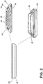
FIG. 2 is a front exploded perspective view of a non-powered accessory system of the present disclosure; -
FIG. 3 is a front exploded perspective view of another embodiment of a non-powered accessory system of the present disclosure; -
FIG. 4 is a top perspective view of a non-powered accessory system with a cover; and -
FIG. 5 is a top partial perspective view of a corner of another embodiment of a non-powered accessory system that includes a temperature gauge; -
FIG. 6 is a front elevational view of a non-powered accessory system of the present disclosure; -
FIG. 7 is a top perspective view of the accessory system ofFIG. 6 ; and -
FIG. 8 is a top perspective view of the accessory system ofFIG. 7 with the cooking stone removed. - The present illustrated embodiments reside primarily in combinations of method steps and apparatus components related to a display mirror. Accordingly, the apparatus components and method steps have been represented, where appropriate, by conventional symbols in the drawings, showing only those specific details that are pertinent to understanding the embodiments of the present disclosure so as not to obscure the disclosure with details that will be readily apparent to those of ordinary skill in the art having the benefit of the description herein. Further, like numerals in the description and drawings represent like elements.
- For purposes of description herein, the terms "upper," "lower," "right," "left," "rear," "front," "vertical," "horizontal," and derivatives thereof shall relate to the disclosure as oriented in
FIG. 1 . Unless stated otherwise, the term "front" shall refer to the surface of the element closer to an intended viewer of the display mirror, and the term "rear" shall refer to the surface of the element further from the intended viewer of the display mirror. However, it is to be understood that the disclosure may assume various alternative orientations, except where expressly specified to the contrary. It is also to be understood that the specific devices and processes illustrated in the attached drawings, and described in the following specification are simply exemplary embodiments of the inventive concepts defined in the appended claims. Hence, specific dimensions and other physical characteristics relating to the embodiments disclosed herein are not to be considered as limiting, unless the claims expressly state otherwise. - The terms "including," "comprises," "comprising," or any other variation thereof, are intended to cover a non-exclusive inclusion, such that a process, method, article, or apparatus that comprises a list of elements does not include only those elements but may include other elements not expressly listed or inherent to such process, method, article, or apparatus. An element proceeded by "comprises a ... " does not, without more constraints, preclude the existence of additional identical elements in the process, method, article, or apparatus that comprises the element.
- With reference to
FIGS. 1-5 ,reference numeral 10 generally illustrates a cooking assembly designed for use in an oven. Thecooking assembly 10 includes agrill rack 12 having aperipheral portion 14 defined by a plurality of laterally extendingwires 16 bound by aperipheral frame 18. Aninner retention portion 20 is defined by a plurality of laterally extendingwires 22 generally co-planar with the plurality of laterally extendingwires 16 of theperipheral portion 14. Theinner retention portion 20 includes aretention border 24. Adrip tray 26 is configured to removably engage theretention border 20, thereby securing thedrip tray 26 laterally. One of asearing pan 30 and acooking stone 32 is configured to be received in thedrip tray 26. - With reference again to
FIGS. 1 and2 , thecooking assembly 10 is generally configured to be used in an oven for cooking food goods. The construction of thecooking assembly 10 is generally designed to simulate cooking on a grill, cooking in a hearth, or in a stone/brick oven. As shown inFIG. 1 , thegrill rack 12 includes a generally planar configuration and may include aspace 40 designed to allow easy insertion and withdrawal of thegrill rack 12 into an oven. In this instance, a portion of theperipheral frame 18 acts as a handle. In addition, thedrip tray 26 is configured to be received in theinner retention portion 20 to prevent lateral movement of thedrip tray 26 forward and rearward or from side to side. It is generally contemplated that thedrip tray 26 may includehandles 42, which may be aligned with and used in concert withhandles 44 of thesearing pan 30. - The
searing pan 30 includes a generally planar construction and may include a plurality of raisedcooking surfaces 46 that extend upwardly from abody portion 48 of thesearing pan 30. In addition, thesearing pan 30 includes a raisededge 50 configured to minimize dripping of juices from food goods disposed on thesearing pan 30 during cooking. Further, thesearing pan 30 may include an open matrix of drip openings to allow juices to flow away from the food goods. - With reference to
FIG. 2 , thedrip tray 26 may include abulbous rim 60 and an angled or chamferedlower edge 62 configured to be received within theinner retention portion 20. Thesearing pan 30 may include alower engagement member 64 configured to engage thebulbous rim 60 of thedrip tray 26. The engagement of thelower engagement member 64 with thebulbous rim 60 ensures that thesearing pan 30 maintains position within thedrip tray 26 during use. - Depending on the desired needs of a user, the
searing pan 30 can be replaced with thecooking stone 32, as shown inFIG. 3 . In this instance, thecooking stone 32 is a generally planar member that includes alower engagement member 70 configured for engagement with thebulbous rim 60 of thedrip tray 26. Thecooking stone 32 can be made from a variety of hard surfaces, including ceramic, granite, etc. - With reference now to
FIG. 4 , anothercooking assembly 10 is illustrated that includes adrip tray 100 havingfeet 102 at each of four corners of thedrip tray 100. Thefeet 102 can be configured to engage an outside edge of at least one corner of a retention border. In addition, thedrip tray 100 is configured to receive asearing pan 104. Thesearing pan 104 is received within thedrip tray 100 and rests slightly below anupper edge 106 of thedrip tray 100. This may be accomplished by constructing thesearing pan 104 to be slightly shorter than the internal height of thedrip tray 100. Alternatively, thesearing pan 104 may rest on an inner ledge that supports a cooling surface of thesearing pan 104 just below theupper edge 106 of thedrip tray 100. In the illustrated embodiment, thesearing pan 104 includes a first plurality ofsearing walls 108 that are parallel and running in a first direction, and a second plurality ofsearing walls 110 that are parallel and running in a second direction. The first plurality ofsearing walls 108 stand slightly higher than the second set of searingwalls 110, such that a top edge of the first plurality ofsearing walls 108 is not coplanar with a top edge of the second plurality ofsearing walls 110. In addition, the illustratedcooking assembly 10 includes alid 112 constructed from a clear or at least partially clear or partially translucent, polymeric material, and which also includes ahandle 114 thereon. Thehandle 114 may be constructed from any of a variety of materials, including metal, plastic, etc. It is generally contemplated that thedrip tray 100 may be used in conjunction with thegrill rack 12 illustrated inFIG. 1 . Thelid 112 is generally configured to enclose thesearing pan 104. - With reference now to
FIG. 5 , it is generally contemplated that any of the searing pans or cooking stones contemplated for use with thecooking assembly 10 of the present disclosure may include atemperature gauge 120 in a corner thereof. Thetemperature gauge 120 relays information pertaining to the temperature of the searing pan or cooking stone so a user knows when the appropriate temperature has been met for cooking. It is also contemplated that thetemperature gauge 120 may be positioned in a variety of other locations. - With reference now to
FIGS. 6-8 , acooking assembly 200 is illustrated, which includes agrill rack 202 having aperipheral portion 204 defined by a plurality of laterally extendingwires 205 bound by aperipheral frame 206. Thegrill rack 202 also includes aninner retention portion 208 defined by aretention border 210. Adrip tray 212 is configured to removably engage theretention border 210, thereby securing thedrip tray 212 laterally. One of a searing pan and acooking stone 214 is configured to be received in or on thedrip tray 212. Thedrip tray 212 generally extends into theinner retention portion 208 and includes aperipheral flange 216 that rests on thegrill rack 202. Thedrip tray 212 also includes a well 218 that extends into theinner retention portion 208 below a planar extent of the laterally extendingwires 205 of theperipheral portion 204. - The
grill rack 202 is generally configured for use with a rail andslide assembly 220. The rail andslide assembly 220 allows for thegrill rack 202 to move relative to alower support rack 222. Thegrill rack 202 is fixedly connected with aslide 224 that linearly moves along arail 226 that may be coupled with an inner wall of an oven. Thelower support rack 222 provides rigidity to the system and may also provide additional support to thedrip tray 212 even if thedrip tray 212 includes a deep well, such that the well rests on thesupport rack 212. As shown inFIG. 7 , the searing pan orcooking stone 214 may includerecesses 230 generally defining handle portions, such that the searing pan orcooking stone 214 may be removed from thedrip tray 212. - It will be understood by one having ordinary skill in the art that construction of the described disclosure and other components is not limited to any specific material. Other exemplary embodiments of the disclosure disclosed herein may be formed from a wide variety of materials, unless described otherwise herein.
- For purposes of this disclosure, the term "coupled" (in all of its forms, couple, coupling, coupled, etc.) generally means the joining of two components (electrical or mechanical) directly or indirectly to one another. Such joining may be stationary in nature or movable in nature. Such joining may be achieved with the two components (electrical or mechanical) and any additional intermediate members being integrally formed as a single unitary body with one another or with the two components. Such joining may be permanent in nature or may be removable or releasable in nature unless otherwise stated.
- It is also important to note that the construction and arrangement of the elements of the disclosure as shown in the exemplary embodiments is illustrative only. Although only a few embodiments of the present innovations have been described in detail in this disclosure, those skilled in the art who review this disclosure will readily appreciate that many modifications are possible (e.g., variations in sizes, dimensions, structures, shapes and proportions of the various elements, values of parameters, mounting arrangements, use of materials, colors, orientations, etc.) without materially departing from the novel teachings and advantages of the subject matter recited. For example, elements shown as integrally formed may be constructed of multiple parts or elements shown as multiple parts may be integrally formed, the operation of the interfaces may be reversed or otherwise varied, the length or width of the structures and/or members or connector or other elements of the system may be varied, the nature or number of adjustment positions provided between the elements may be varied. It should be noted that the elements and/or assemblies of the system may be constructed from any of a wide variety of materials that provide sufficient strength or durability, in any of a wide variety of colors, textures, and combinations. Accordingly, all such modifications are intended to be included within the scope of the present innovations. Other substitutions, modifications, changes, and omissions may be made in the design, operating conditions, and arrangement of the desired and other exemplary embodiments without departing from the spirit of the present innovations.
- It will be understood that any described processes or steps within described processes may be combined with other disclosed processes or steps to form structures within the scope of the present disclosure. The exemplary structures and processes disclosed herein are for illustrative purposes and are not to be construed as limiting.
Claims (12)
- A cooking assembly (10, 200) comprising:a grill rack (12, 202) including:a peripheral portion (14, 204) defined by a plurality of laterally extending wires (16, 205) bound by a peripheral frame (18, 206); andan inner retention portion (20, 208) defined by a plurality of laterally extending wires (22) generally co-planar with the plurality of laterally extending wires (16, 205) of the peripheral portion (14, 204), the inner retention portion (20, 208) including a retention border (24, 210);a drip tray (26, 100, 212) configured to removably engage the retention border (24, 210), thereby securing the drip tray (26, 100, 212) laterally; andone of a searing pan (30, 104) and a cooking stone (32) configured to be received in the drip tray (26, 100, 212).
- The cooking assembly (10, 200) of claim 1, further comprising:a temperature gauge (120) disposed on the searing pan (30, 104).
- The cooking assembly (10, 200) of either of claims 1 or 2, further comprising:a lid (112) configured to enclose a top portion of the searing pan (30, 104).
- The cooking assembly (10, 200) of claim 3, wherein the lid (112) is constructed from an at least partially translucent polymeric material.
- The cooking assembly (10, 200) of any of claims 1-4, wherein the searing pan (30, 104) includes an open matrix of drip openings.
- The cooking assembly (10, 200) of any of claims 1-5, wherein at least one of the cooking stone (32) and the searing pan (30, 104) includes handle apertures (44) proximate handles (42) of the drip tray (26, 100, 212).
- The cooking assembly (10, 200) of any of claims 1-6, further comprising:feet (102) configured to engage an outside edge of at least one corner of the retention border (24, 210).
- The cooking assembly (10, 200) of any of claims 3-7, wherein the lid (112) includes a handle (114).
- The cooking assembly (10, 200) of any of claims 1-8, wherein the searing pan (30, 104) includes raised cooking features 46.
- The cooking assembly (10, 200) of any of claims 1-9, wherein the grill rack (12, 202) defines a space 40 configured to allow for easy insertion and withdrawal of the grill rack (12, 202) into an oven.
- The cooking assembly (10, 200) of any of claims 1-10, wherein the peripheral frame (18, 206) defines a handle of the grill rack (12, 202).
- The cooking assembly (10, 200) of any of claims 1-11, wherein the cooking stone (32) includes a lower engagement member (70) configured for engagement with the drip tray (26, 100, 212).
Applications Claiming Priority (1)
| Application Number | Priority Date | Filing Date | Title |
|---|---|---|---|
| US15/215,925 US10702098B2 (en) | 2016-07-21 | 2016-07-21 | Oven based non-powered accessory system |
Publications (1)
| Publication Number | Publication Date |
|---|---|
| EP3273166A1 true EP3273166A1 (en) | 2018-01-24 |
Family
ID=59381188
Family Applications (1)
| Application Number | Title | Priority Date | Filing Date |
|---|---|---|---|
| EP17182130.9A Withdrawn EP3273166A1 (en) | 2016-07-21 | 2017-07-19 | Oven based non-powered accessory system |
Country Status (2)
| Country | Link |
|---|---|
| US (2) | US10702098B2 (en) |
| EP (1) | EP3273166A1 (en) |
Families Citing this family (5)
| Publication number | Priority date | Publication date | Assignee | Title |
|---|---|---|---|---|
| US10702098B2 (en) | 2016-07-21 | 2020-07-07 | Whirlpool Corporation | Oven based non-powered accessory system |
| US20200390280A1 (en) * | 2019-06-14 | 2020-12-17 | Thomas Buttram | ArmaDee |
| US11933499B2 (en) * | 2021-10-05 | 2024-03-19 | Haier Us Appliance Solutions, Inc. | Removable bottom panel for an oven appliance |
| US20230371741A1 (en) * | 2022-05-17 | 2023-11-23 | Shannon Dinkins | Pizza Cooking Stone Device |
| US12507828B1 (en) * | 2022-09-12 | 2025-12-30 | Chandradai Latchminarine | Grilling device for use with stovetops |
Citations (7)
| Publication number | Priority date | Publication date | Assignee | Title |
|---|---|---|---|---|
| US3063441A (en) * | 1959-08-26 | 1962-11-13 | Whirlpool Co | Cooking apparatus |
| US5490452A (en) * | 1994-08-12 | 1996-02-13 | Weber-Stephen Products Co. | Cooking grate assembly for barbecue grills |
| US6463844B1 (en) * | 2000-08-04 | 2002-10-15 | Testrite Baparoma International, Llc | Baking pan |
| US20050051157A1 (en) * | 2003-09-05 | 2005-03-10 | Robert Cuomo | Kit, apparatus and method for use in cooking over an intense heat source |
| EP1994828A2 (en) * | 2007-05-22 | 2008-11-26 | Whirpool Corporation | Oven and pan arrangement for steam cooking of foods |
| EP2615380A1 (en) * | 2012-01-11 | 2013-07-17 | BSH Bosch und Siemens Hausgeräte GmbH | Cooking chamber insert |
| US20160095469A1 (en) * | 2014-10-07 | 2016-04-07 | Whirlpool Corporation | Powered cooking accessory for an oven cavity |
Family Cites Families (27)
| Publication number | Priority date | Publication date | Assignee | Title |
|---|---|---|---|---|
| US620927A (en) * | 1899-03-14 | Delzon g | ||
| US4092909A (en) * | 1976-07-12 | 1978-06-06 | Phillips John M | Perforated self-draining meatloaf baking pan |
| US4131109A (en) * | 1977-05-25 | 1978-12-26 | Jordan College | Solar collector |
| DE3238768A1 (en) * | 1982-10-20 | 1984-04-26 | Kurt Wolf & Co Kg, 7547 Wildbad | COOKING VESSEL FROM COOKER AND LID, ESPECIALLY STEAM PRESSURE COOKER |
| US4706832A (en) | 1985-03-12 | 1987-11-17 | Salday Products Corporation | Home baker's hearth accessory for baking old world bread in a conventional home oven |
| US4640265A (en) | 1986-02-24 | 1987-02-03 | Romo H Duane | Insert for converting a conventional home oven into a pizza oven |
| DE4008838C1 (en) * | 1990-03-20 | 1991-05-16 | Rittal-Werk Rudolf Loh Gmbh & Co Kg, 6348 Herborn, De | |
| JPH0761301B2 (en) * | 1993-03-05 | 1995-07-05 | 株式会社サン食材 | High temperature dry steam cooker |
| US5562023A (en) * | 1996-03-19 | 1996-10-08 | Harrison; Calvin L. | Rib rack with sauce pan |
| US5848691A (en) * | 1997-07-07 | 1998-12-15 | Wilson-Cook Medical Inc. | Package for sphincterotome or catheter including structure maintaining shape of distal tip |
| US5970855A (en) * | 1998-03-19 | 1999-10-26 | Patterson; Vance M. | Portable kitchen with movable cooking unit |
| US6262399B1 (en) * | 1999-09-09 | 2001-07-17 | Eastern Sources Housewares (Hong Kong) Limited | Grill |
| US6640695B2 (en) | 2002-02-07 | 2003-11-04 | Steven Stark | Pizza insert for barbeque grill |
| US7426885B2 (en) * | 2004-12-23 | 2008-09-23 | Mclemore Don | Cooking device |
| US7372000B2 (en) | 2004-04-13 | 2008-05-13 | Stockley Enterprises, Llc | Air control for a brick oven |
| WO2006091475A2 (en) | 2005-02-24 | 2006-08-31 | Bon Chef, Inc. | Grill pan with adjusting hinge |
| US20080047915A1 (en) | 2006-08-23 | 2008-02-28 | Electrolux Home Products, Inc. | Baking stone rack |
| AU2008200214B2 (en) * | 2007-01-24 | 2013-03-28 | Lico (Hk) Manufacturing Ltd | Baking Pan |
| WO2009088809A1 (en) * | 2008-01-02 | 2009-07-16 | W.C. Bradley Company | Temperature measurement means for cooking appliances |
| US20130206127A1 (en) * | 2011-09-28 | 2013-08-15 | Sizzlestone, Llc | Metamorphic Stone Table-Top Grill |
| US20130118474A1 (en) | 2011-11-16 | 2013-05-16 | Illinois Tool Works Inc. | Elevated support structure for enabling vertical food orientation |
| CA2863101A1 (en) * | 2012-02-22 | 2013-08-29 | Hearthmark, Llc | Jam and jelly maker |
| US9033181B2 (en) | 2012-08-28 | 2015-05-19 | Michael FERIOLA | Combination baking pan and cooling rack |
| US9820608B2 (en) * | 2012-09-12 | 2017-11-21 | Gwendolyn Kessell | Apparatus and method for flipping food |
| TR201900429T4 (en) | 2012-09-14 | 2019-02-21 | Tingley Jason | Baking tray with interchangeable cooking slots. |
| USD691846S1 (en) * | 2013-05-10 | 2013-10-22 | Frank DeMaio | Stovetop mini oven |
| US10702098B2 (en) | 2016-07-21 | 2020-07-07 | Whirlpool Corporation | Oven based non-powered accessory system |
-
2016
- 2016-07-21 US US15/215,925 patent/US10702098B2/en active Active
-
2017
- 2017-07-19 EP EP17182130.9A patent/EP3273166A1/en not_active Withdrawn
-
2020
- 2020-05-21 US US16/879,888 patent/US11672378B2/en active Active
Patent Citations (7)
| Publication number | Priority date | Publication date | Assignee | Title |
|---|---|---|---|---|
| US3063441A (en) * | 1959-08-26 | 1962-11-13 | Whirlpool Co | Cooking apparatus |
| US5490452A (en) * | 1994-08-12 | 1996-02-13 | Weber-Stephen Products Co. | Cooking grate assembly for barbecue grills |
| US6463844B1 (en) * | 2000-08-04 | 2002-10-15 | Testrite Baparoma International, Llc | Baking pan |
| US20050051157A1 (en) * | 2003-09-05 | 2005-03-10 | Robert Cuomo | Kit, apparatus and method for use in cooking over an intense heat source |
| EP1994828A2 (en) * | 2007-05-22 | 2008-11-26 | Whirpool Corporation | Oven and pan arrangement for steam cooking of foods |
| EP2615380A1 (en) * | 2012-01-11 | 2013-07-17 | BSH Bosch und Siemens Hausgeräte GmbH | Cooking chamber insert |
| US20160095469A1 (en) * | 2014-10-07 | 2016-04-07 | Whirlpool Corporation | Powered cooking accessory for an oven cavity |
Also Published As
| Publication number | Publication date |
|---|---|
| US20180020873A1 (en) | 2018-01-25 |
| US11672378B2 (en) | 2023-06-13 |
| US10702098B2 (en) | 2020-07-07 |
| US20200281401A1 (en) | 2020-09-10 |
Similar Documents
| Publication | Publication Date | Title |
|---|---|---|
| US11672378B2 (en) | Oven based non-powered accessory system | |
| EP2042811B1 (en) | Telescopic rail system | |
| EP2910170B1 (en) | Tray supporting apparatus for dishwasher, cutlery tray assembly and dishwasher | |
| EP1892477A2 (en) | Baking stone rack | |
| US8479926B1 (en) | Pot lid holding system | |
| US9033181B2 (en) | Combination baking pan and cooling rack | |
| CN101133748B (en) | Full depth rack | |
| US20210251422A1 (en) | Rack assembly | |
| JP4513103B2 (en) | Holder for eating utensils | |
| EP1966542B1 (en) | An oven | |
| US20190053662A1 (en) | Clamshell griddle | |
| US20100181442A1 (en) | Device for placing receptacles, such as plates, provided with a product | |
| EP4388939B1 (en) | Shelf for furniture, and related item of furniture | |
| JP6067461B2 (en) | grill | |
| USD527228S1 (en) | Vertical utensil rest | |
| US20130014741A1 (en) | Multimount oven rack | |
| JP5886131B2 (en) | grill | |
| US20230194102A1 (en) | Removable bottom trim | |
| CA2935168A1 (en) | Cover for holding tray | |
| USD796892S1 (en) | Grill | |
| GB2430733A (en) | Adjustable and divisible oven or barbecue shelf | |
| CN223287051U (en) | A pot holder | |
| US7861442B2 (en) | Food-product preparation kit, food-product preparation apparatus, and methods of use | |
| JP3225175U (en) | Cookware set | |
| JP2004321247A (en) | Draining plate and kitchen cabinet equipped with the same |
Legal Events
| Date | Code | Title | Description |
|---|---|---|---|
| PUAI | Public reference made under article 153(3) epc to a published international application that has entered the european phase |
Free format text: ORIGINAL CODE: 0009012 |
|
| STAA | Information on the status of an ep patent application or granted ep patent |
Free format text: STATUS: THE APPLICATION HAS BEEN PUBLISHED |
|
| AK | Designated contracting states |
Kind code of ref document: A1 Designated state(s): AL AT BE BG CH CY CZ DE DK EE ES FI FR GB GR HR HU IE IS IT LI LT LU LV MC MK MT NL NO PL PT RO RS SE SI SK SM TR |
|
| AX | Request for extension of the european patent |
Extension state: BA ME |
|
| STAA | Information on the status of an ep patent application or granted ep patent |
Free format text: STATUS: THE APPLICATION IS DEEMED TO BE WITHDRAWN |
|
| 18D | Application deemed to be withdrawn |
Effective date: 20180725 |