EP3273157B1 - Led lamp electrical connection member - Google Patents
Led lamp electrical connection member Download PDFInfo
- Publication number
- EP3273157B1 EP3273157B1 EP16834545.2A EP16834545A EP3273157B1 EP 3273157 B1 EP3273157 B1 EP 3273157B1 EP 16834545 A EP16834545 A EP 16834545A EP 3273157 B1 EP3273157 B1 EP 3273157B1
- Authority
- EP
- European Patent Office
- Prior art keywords
- elastic clamping
- clamping portion
- abutting portion
- conductive
- input terminal
- Prior art date
- Legal status (The legal status is an assumption and is not a legal conclusion. Google has not performed a legal analysis and makes no representation as to the accuracy of the status listed.)
- Active
Links
Images

Classifications
-
- F—MECHANICAL ENGINEERING; LIGHTING; HEATING; WEAPONS; BLASTING
- F21—LIGHTING
- F21V—FUNCTIONAL FEATURES OR DETAILS OF LIGHTING DEVICES OR SYSTEMS THEREOF; STRUCTURAL COMBINATIONS OF LIGHTING DEVICES WITH OTHER ARTICLES, NOT OTHERWISE PROVIDED FOR
- F21V23/00—Arrangement of electric circuit elements in or on lighting devices
- F21V23/06—Arrangement of electric circuit elements in or on lighting devices the elements being coupling devices, e.g. connectors
-
- F—MECHANICAL ENGINEERING; LIGHTING; HEATING; WEAPONS; BLASTING
- F21—LIGHTING
- F21K—NON-ELECTRIC LIGHT SOURCES USING LUMINESCENCE; LIGHT SOURCES USING ELECTROCHEMILUMINESCENCE; LIGHT SOURCES USING CHARGES OF COMBUSTIBLE MATERIAL; LIGHT SOURCES USING SEMICONDUCTOR DEVICES AS LIGHT-GENERATING ELEMENTS; LIGHT SOURCES NOT OTHERWISE PROVIDED FOR
- F21K9/00—Light sources using semiconductor devices as light-generating elements, e.g. using light-emitting diodes [LED] or lasers
- F21K9/20—Light sources comprising attachment means
- F21K9/23—Retrofit light sources for lighting devices with a single fitting for each light source, e.g. for substitution of incandescent lamps with bayonet or threaded fittings
- F21K9/238—Arrangement or mounting of circuit elements integrated in the light source
-
- F—MECHANICAL ENGINEERING; LIGHTING; HEATING; WEAPONS; BLASTING
- F21—LIGHTING
- F21V—FUNCTIONAL FEATURES OR DETAILS OF LIGHTING DEVICES OR SYSTEMS THEREOF; STRUCTURAL COMBINATIONS OF LIGHTING DEVICES WITH OTHER ARTICLES, NOT OTHERWISE PROVIDED FOR
- F21V23/00—Arrangement of electric circuit elements in or on lighting devices
- F21V23/003—Arrangement of electric circuit elements in or on lighting devices the elements being electronics drivers or controllers for operating the light source, e.g. for a LED array
- F21V23/004—Arrangement of electric circuit elements in or on lighting devices the elements being electronics drivers or controllers for operating the light source, e.g. for a LED array arranged on a substrate, e.g. a printed circuit board
- F21V23/006—Arrangement of electric circuit elements in or on lighting devices the elements being electronics drivers or controllers for operating the light source, e.g. for a LED array arranged on a substrate, e.g. a printed circuit board the substrate being distinct from the light source holder
-
- H—ELECTRICITY
- H01—ELECTRIC ELEMENTS
- H01R—ELECTRICALLY-CONDUCTIVE CONNECTIONS; STRUCTURAL ASSOCIATIONS OF A PLURALITY OF MUTUALLY-INSULATED ELECTRICAL CONNECTING ELEMENTS; COUPLING DEVICES; CURRENT COLLECTORS
- H01R12/00—Structural associations of a plurality of mutually-insulated electrical connecting elements, specially adapted for printed circuits, e.g. printed circuit boards [PCB], flat or ribbon cables, or like generally planar structures, e.g. terminal strips, terminal blocks; Coupling devices specially adapted for printed circuits, flat or ribbon cables, or like generally planar structures; Terminals specially adapted for contact with, or insertion into, printed circuits, flat or ribbon cables, or like generally planar structures
- H01R12/70—Coupling devices
- H01R12/71—Coupling devices for rigid printing circuits or like structures
- H01R12/712—Coupling devices for rigid printing circuits or like structures co-operating with the surface of the printed circuit or with a coupling device exclusively provided on the surface of the printed circuit
- H01R12/716—Coupling device provided on the PCB
-
- H—ELECTRICITY
- H01—ELECTRIC ELEMENTS
- H01R—ELECTRICALLY-CONDUCTIVE CONNECTIONS; STRUCTURAL ASSOCIATIONS OF A PLURALITY OF MUTUALLY-INSULATED ELECTRICAL CONNECTING ELEMENTS; COUPLING DEVICES; CURRENT COLLECTORS
- H01R12/00—Structural associations of a plurality of mutually-insulated electrical connecting elements, specially adapted for printed circuits, e.g. printed circuit boards [PCB], flat or ribbon cables, or like generally planar structures, e.g. terminal strips, terminal blocks; Coupling devices specially adapted for printed circuits, flat or ribbon cables, or like generally planar structures; Terminals specially adapted for contact with, or insertion into, printed circuits, flat or ribbon cables, or like generally planar structures
- H01R12/70—Coupling devices
- H01R12/71—Coupling devices for rigid printing circuits or like structures
- H01R12/712—Coupling devices for rigid printing circuits or like structures co-operating with the surface of the printed circuit or with a coupling device exclusively provided on the surface of the printed circuit
- H01R12/716—Coupling device provided on the PCB
- H01R12/718—Contact members provided on the PCB without an insulating housing
-
- H—ELECTRICITY
- H01—ELECTRIC ELEMENTS
- H01R—ELECTRICALLY-CONDUCTIVE CONNECTIONS; STRUCTURAL ASSOCIATIONS OF A PLURALITY OF MUTUALLY-INSULATED ELECTRICAL CONNECTING ELEMENTS; COUPLING DEVICES; CURRENT COLLECTORS
- H01R12/00—Structural associations of a plurality of mutually-insulated electrical connecting elements, specially adapted for printed circuits, e.g. printed circuit boards [PCB], flat or ribbon cables, or like generally planar structures, e.g. terminal strips, terminal blocks; Coupling devices specially adapted for printed circuits, flat or ribbon cables, or like generally planar structures; Terminals specially adapted for contact with, or insertion into, printed circuits, flat or ribbon cables, or like generally planar structures
- H01R12/70—Coupling devices
- H01R12/71—Coupling devices for rigid printing circuits or like structures
- H01R12/72—Coupling devices for rigid printing circuits or like structures coupling with the edge of the rigid printed circuits or like structures
- H01R12/722—Coupling devices for rigid printing circuits or like structures coupling with the edge of the rigid printed circuits or like structures coupling devices mounted on the edge of the printed circuits
-
- H—ELECTRICITY
- H01—ELECTRIC ELEMENTS
- H01R—ELECTRICALLY-CONDUCTIVE CONNECTIONS; STRUCTURAL ASSOCIATIONS OF A PLURALITY OF MUTUALLY-INSULATED ELECTRICAL CONNECTING ELEMENTS; COUPLING DEVICES; CURRENT COLLECTORS
- H01R13/00—Details of coupling devices of the kinds covered by groups H01R12/70 or H01R24/00 - H01R33/00
- H01R13/02—Contact members
- H01R13/10—Sockets for co-operation with pins or blades
- H01R13/14—Resiliently-mounted rigid sockets
-
- H—ELECTRICITY
- H01—ELECTRIC ELEMENTS
- H01R—ELECTRICALLY-CONDUCTIVE CONNECTIONS; STRUCTURAL ASSOCIATIONS OF A PLURALITY OF MUTUALLY-INSULATED ELECTRICAL CONNECTING ELEMENTS; COUPLING DEVICES; CURRENT COLLECTORS
- H01R13/00—Details of coupling devices of the kinds covered by groups H01R12/70 or H01R24/00 - H01R33/00
- H01R13/02—Contact members
- H01R13/15—Pins, blades or sockets having separate spring member for producing or increasing contact pressure
- H01R13/18—Pins, blades or sockets having separate spring member for producing or increasing contact pressure with the spring member surrounding the socket
-
- F—MECHANICAL ENGINEERING; LIGHTING; HEATING; WEAPONS; BLASTING
- F21—LIGHTING
- F21Y—INDEXING SCHEME ASSOCIATED WITH SUBCLASSES F21K, F21L, F21S and F21V, RELATING TO THE FORM OR THE KIND OF THE LIGHT SOURCES OR OF THE COLOUR OF THE LIGHT EMITTED
- F21Y2115/00—Light-generating elements of semiconductor light sources
- F21Y2115/10—Light-emitting diodes [LED]
-
- H—ELECTRICITY
- H01—ELECTRIC ELEMENTS
- H01R—ELECTRICALLY-CONDUCTIVE CONNECTIONS; STRUCTURAL ASSOCIATIONS OF A PLURALITY OF MUTUALLY-INSULATED ELECTRICAL CONNECTING ELEMENTS; COUPLING DEVICES; CURRENT COLLECTORS
- H01R12/00—Structural associations of a plurality of mutually-insulated electrical connecting elements, specially adapted for printed circuits, e.g. printed circuit boards [PCB], flat or ribbon cables, or like generally planar structures, e.g. terminal strips, terminal blocks; Coupling devices specially adapted for printed circuits, flat or ribbon cables, or like generally planar structures; Terminals specially adapted for contact with, or insertion into, printed circuits, flat or ribbon cables, or like generally planar structures
- H01R12/50—Fixed connections
- H01R12/51—Fixed connections for rigid printed circuits or like structures
- H01R12/55—Fixed connections for rigid printed circuits or like structures characterised by the terminals
- H01R12/57—Fixed connections for rigid printed circuits or like structures characterised by the terminals surface mounting terminals
-
- H—ELECTRICITY
- H01—ELECTRIC ELEMENTS
- H01R—ELECTRICALLY-CONDUCTIVE CONNECTIONS; STRUCTURAL ASSOCIATIONS OF A PLURALITY OF MUTUALLY-INSULATED ELECTRICAL CONNECTING ELEMENTS; COUPLING DEVICES; CURRENT COLLECTORS
- H01R12/00—Structural associations of a plurality of mutually-insulated electrical connecting elements, specially adapted for printed circuits, e.g. printed circuit boards [PCB], flat or ribbon cables, or like generally planar structures, e.g. terminal strips, terminal blocks; Coupling devices specially adapted for printed circuits, flat or ribbon cables, or like generally planar structures; Terminals specially adapted for contact with, or insertion into, printed circuits, flat or ribbon cables, or like generally planar structures
- H01R12/70—Coupling devices
- H01R12/71—Coupling devices for rigid printing circuits or like structures
- H01R12/72—Coupling devices for rigid printing circuits or like structures coupling with the edge of the rigid printed circuits or like structures
- H01R12/722—Coupling devices for rigid printing circuits or like structures coupling with the edge of the rigid printed circuits or like structures coupling devices mounted on the edge of the printed circuits
- H01R12/728—Coupling devices without an insulating housing provided on the edge of the PCB
-
- H—ELECTRICITY
- H01—ELECTRIC ELEMENTS
- H01R—ELECTRICALLY-CONDUCTIVE CONNECTIONS; STRUCTURAL ASSOCIATIONS OF A PLURALITY OF MUTUALLY-INSULATED ELECTRICAL CONNECTING ELEMENTS; COUPLING DEVICES; CURRENT COLLECTORS
- H01R12/00—Structural associations of a plurality of mutually-insulated electrical connecting elements, specially adapted for printed circuits, e.g. printed circuit boards [PCB], flat or ribbon cables, or like generally planar structures, e.g. terminal strips, terminal blocks; Coupling devices specially adapted for printed circuits, flat or ribbon cables, or like generally planar structures; Terminals specially adapted for contact with, or insertion into, printed circuits, flat or ribbon cables, or like generally planar structures
- H01R12/70—Coupling devices
- H01R12/71—Coupling devices for rigid printing circuits or like structures
- H01R12/72—Coupling devices for rigid printing circuits or like structures coupling with the edge of the rigid printed circuits or like structures
- H01R12/73—Coupling devices for rigid printing circuits or like structures coupling with the edge of the rigid printed circuits or like structures connecting to other rigid printed circuits or like structures
- H01R12/735—Printed circuits including an angle between each other
- H01R12/737—Printed circuits being substantially perpendicular to each other
-
- H—ELECTRICITY
- H01—ELECTRIC ELEMENTS
- H01R—ELECTRICALLY-CONDUCTIVE CONNECTIONS; STRUCTURAL ASSOCIATIONS OF A PLURALITY OF MUTUALLY-INSULATED ELECTRICAL CONNECTING ELEMENTS; COUPLING DEVICES; CURRENT COLLECTORS
- H01R13/00—Details of coupling devices of the kinds covered by groups H01R12/70 or H01R24/00 - H01R33/00
- H01R13/02—Contact members
- H01R13/10—Sockets for co-operation with pins or blades
- H01R13/11—Resilient sockets
- H01R13/113—Resilient sockets co-operating with pins or blades having a rectangular transverse section
Definitions
- the present invention relates to the field of lighting, and particularly to an electrical connector of an LED light.
- the LED light usually includes a light source board and a driver board, and the driver board needs to be electrically connected with the light source board to realize the purpose of driving an LED light source on the light source board to radiate light.
- an electrical connection between the light source board and the driver board is typically realized by welding wires, so as to achieve the purpose of connecting a driving power.
- the wires need to be manually threaded and welded, therefore, the production process is complicated, inefficient and time-wasted, and the wires cannot be easily positioned and arranged, which causes automated production to be difficultly implemented.
- there is an improved scheme which utilizes terminals so as to facilitate the automatic production.
- these terminals are often easy to deformation after a long term usage, leading to a failure of the electrical connection and a poor reliability.
- CN 203771347 U shows an electric connector of an LED lamp used for connecting electrodes between a light source substrate and a drive plate of the LED lamp, and comprises two input terminals and two output terminals, wherein one end of each input terminal is fixed to the drive plate of the LED lamp and is electrically connected with the drive plate, each output terminal comprising a conductive end and an elastic clamping portion, each conductive end comprises a conductive pin, the conductive ends are fixed to the light source substrate through the conductive pins and are electrically connected with the light source substrate, and the elastic clamping portions are integrally arranged at the conductive ends.
- this document CN 203771347 U also discloses (references to this document between brackets) an electrical assembly (100, figure 2 ) for a LED light (implicit), the assembly comprising a light source board (20) and a driver board (40) of the LED light and an electrical connector ( figures 3 and 4 ) configured to perform an electrical connection between the light source board (20) and the driver board (40), the electrical connector ( figures 3 and 4 ) comprising an input terminal (12a) and an output terminal (11), wherein one end of the input terminal (12) is fixed on the driver board (40, see figure 5) of the LED light and is electrically connected with the driver board (implicit), the output terminal (11) comprises a conductive end (342), an elastic clamping portion (343) and an abutting portion (344), the conductive end (342) comprises a conductive leg (341; see figure 3 ), the conductive end (342) is fixed onto and electrically connected with the light source board (20, see figure 5) via the conductive leg (341),
- EP 1341264 A2 discloses an electrical contact receiving a corresponding contact blade.
- the electrical contact has contact arms for contacting the contact blade and contact pins for contacting a circuit board.
- a lateral frame is attached to the contact arms and has a substantially rectangular cross-section.
- the contact pins are connected to the contact arms by a transition piece.
- the transition piece is formed substantially parallel to the circuit board and has a bend that separates the contact arms from the contact pins.
- CN 204100183 U discloses a simple and firm type metal female end which comprises a bottom plate.
- the bottom plate is provided with weld legs to achieve electric connection with a light source plate.
- An insertion opening allowing a male end to penetrate through is formed in the bottom plate.
- the left side edge and the right side edge of the bottom plate firstly extend upwards, then relatively extend to the part above the insertion opening and then are bent downwards to form an elastic clamp to allow the male end to be inserted therein to achieve electric connection.
- the two ends of the elastic clamp incline leftwards and rightwards respectively to penetrate through the insertion opening and then hook the edges of the insertion opening.
- US 4640561 A discloses a unitary retainer socket device for providing positive interconnection between a male pin conductor of an electrical instrument and exposed conductor runs of a flexible printed circuit material is formed to be inserted into and extend from both ends of an open ended aperture in a rigid panel that supports the flexible printed circuit.
- a base element is centrally formed in the socket and has spring biasing tabs extending therefrom to prevent insertion of the base element into the support panel aperture and to provide holding forces to the flexible circuit material against the surface of the support panel. Pairs of legs extend from the base element at a distance that exceeds the depth of the support panel aperture so as to extend therethrough. Electrical contacts of the socket are compressed against the side walls of the support panel aperture by insertion of the male pin conductor in the socket and provide positive electrical contact to the exposed conductor runs of the printed circuit material that extends into the support panel aperture along the side walls.
- an electrical assembly for a LED light comprising a light source board and a driver board of the LED light and an electrical connector configured to perform an electrical connection between the light source board and the driver board.
- the electrical connector includes an input terminal and an output terminal, with one end of the input terminal fixed on the driver board of the LED light and electrically connected with the driver board.
- the output terminal includes a conductive end, an elastic clamping portion, and an abutting portion.
- the conductive end includes a conductive leg, the conductive end is fixed onto and electrically connected with the light source board via the conductive leg.
- the elastic clamping portion and the abutting portion are provided on the conductive end. In an assembled state, the other end of the input terminal elastically abuts against one side of the elastic clamping portion and the abutting portion abuts against the other side of the elastic clamping portion.
- the electrical connector of the LED light is provided with the input terminal and the output terminal.
- the driver board, the input terminal, the output terminal, and the light source board are electrically connected in order.
- the output terminal is provided with the elastic clamping portion and the abutting portion.
- the other end of the input terminal elastically abuts against one side of the elastic clamping portion, and the abutting portion abuts against the other side of the elastic clamping portion.
- the abutting portion can provide a reaction force for the elastic clamping portion, so that an electrical contact between the elastic clamping portion and the input terminal is tighter and is not easy to loosen, and enabling the electrical connector of the LED light to have the advantages of simple structure and high reliability.
- the elastic clamping portion and the abutting portion are both integrally provided on the conductive end, and a bottom of the elastic clamping portion is connected to the conductive end, and a top of the elastic clamping portion is obliquely bent in a direction away from the conductive end.
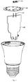
- Fig. 1 is a perspective exploded view of a first embodiment of an electrical connector of an LED light of the present invention.
- the electrical connector of the LED light is used for realizing an electrical connection between a light source board 30 and a driver board 40 of the LED light.
- the electrical connector of the LED light includes an input terminal 10 and an output terminal 20, one end of the input terminal 10 is fixed on the driver board 40 of the LED light and is electrically connected with the driver board 40.
- the output terminal 20 includes a conductive end 21, an elastic clamping portion 22, and an abutting portion 23.
- the elastic clamping portion 22 and the abutting portion 23 are provided on the conductive end 21, and in this embodiment, the elastic clamping portion 22 and the abutting portion 23 are both integrally provided on the conductive end 21.
- the conductive end 21 is made of metal material integrally.
- the conductive end 21 includes a conductive leg 211, the conductive end 21 is fixed onto and electrically connected with the light source board 30 via the conductive leg 211.
- the conductive leg 211 is welded on the light source board 30.
- a bottom of the elastic clamping portion 22 is integrally connected to the conductive end 21, and a top of the elastic clamping portion 22 is obliquely bent in a direction away from the conductive end 21.
- the elastic clamping portion 22 is in number of two, these elastic clamping portions are symmetrically disposed opposite to each other, and form a structure in a shape of Chinese character for "8", and these elastic clamping portions elastically abuts against two side walls of the input terminal 10, respectively.
- the conductive end 21 is further provided thereon with a through hole 212, these elastic clamping portions 22 are symmetrically provided at both sides of the through hole 212, and the input terminal 10 passes through the through hole (212) so as to be electrically connected with these elastic clamping portions 22.
- the abutting portion 23 is of an elastic sheet structure, with the structure bent to have a shape of Chinese character for "door".
- One end of the abutting portion 23 is fixed on the conductive end 21, and the other end of the abutting portion 23 abuts, after being bent, against the elastic clamping portion 22.
- a bottom of the other end of the abutting portion 23 abuts against the elastic clamping portion 22.
- Each of the elastic clamping portion 22 is provided thereon with openings, so that each of the elastic clamping portion 22 forms a comb-shaped structure.
- the comb-shaped structures of these elastic clamping portions 22 are alternatively disposed.
- the elasticity of the elastic clamping portion 22 is improved; and in another aspect, when the input terminal 10 abuts against the elastic clamping portions 22, the comb-shaped structures can be interlaced so as to provide electrical contact at multiple points, which improves the reliability of the electrical connection.
- the other end of the input terminal 10 elastically abuts against one side of the elastic clamping portion 22, and the abutting portion 23 abuts against the other side of the elastic clamping portion.
- the other end of the input terminal 10 elastically abuts against the top of the elastic clamping portion 22.
- the abutting portion 23 abuts against a middle part of the elastic clamping portion 22. In this way, the input terminal 10 is spaced apart from the abutting portion 23, so that a deformation range of the elastic clamping portion 22 can be effectively limited.
- the electrical connector of the LED light is provided with the input terminal 10 and the output terminal 20, the driver board 40, the input terminal 10, the output terminal 20, and the light source board 30 are electrically connected in order.
- the output terminal is provided with the elastic clamping portion 22 and the abutting portion 23. In the assembled state, the other end of the input terminal 10 elastically abuts against one side of the elastic clamping portion 22, and the abutting portion 23 abuts against the other side of the elastic clamping portion.
- the abutting portion 23 can provide a reaction force for the elastic clamping portion 22, so that an electrical contact between the elastic clamping portion 2 and the input terminal 10 is tighter and is not easy to loosen, and enabling the electrical connector of the LED light to have the advantages of simple structure and high reliability.
- the abutting portion 23 may be of a rigid structure, one end of the abutting portion 23 is fixed on the conductive end 21, and the other end of the abutting portion 23 abuts against the middle part of the elastic clamping portion 22. Which can also serve the function of limiting the deformation range of the elastic clamping portion 22.
Landscapes
- Engineering & Computer Science (AREA)
- General Engineering & Computer Science (AREA)
- Microelectronics & Electronic Packaging (AREA)
- Physics & Mathematics (AREA)
- Optics & Photonics (AREA)
- Led Device Packages (AREA)
- Details Of Connecting Devices For Male And Female Coupling (AREA)
- Fastening Of Light Sources Or Lamp Holders (AREA)
Description
- The present invention relates to the field of lighting, and particularly to an electrical connector of an LED light.
- With the rising of environmental awareness all around the world, it is rapidly developed to apply LED lights in the indoor lightning field. At present, the LED light usually includes a light source board and a driver board, and the driver board needs to be electrically connected with the light source board to realize the purpose of driving an LED light source on the light source board to radiate light. At present, an electrical connection between the light source board and the driver board is typically realized by welding wires, so as to achieve the purpose of connecting a driving power. As to such a connection method, the wires need to be manually threaded and welded, therefore, the production process is complicated, inefficient and time-wasted, and the wires cannot be easily positioned and arranged, which causes automated production to be difficultly implemented. At present, there is an improved scheme which utilizes terminals so as to facilitate the automatic production. However, these terminals are often easy to deformation after a long term usage, leading to a failure of the electrical connection and a poor reliability.
- An example of the background art is shown in
CN 203771347 U , which shows an electric connector of an LED lamp used for connecting electrodes between a light source substrate and a drive plate of the LED lamp, and comprises two input terminals and two output terminals, wherein one end of each input terminal is fixed to the drive plate of the LED lamp and is electrically connected with the drive plate, each output terminal comprising a conductive end and an elastic clamping portion, each conductive end comprises a conductive pin, the conductive ends are fixed to the light source substrate through the conductive pins and are electrically connected with the light source substrate, and the elastic clamping portions are integrally arranged at the conductive ends. - It should be noted that this document
CN 203771347 U also discloses (references to this document between brackets) an electrical assembly (100,figure 2 ) for a LED light (implicit), the assembly comprising a light source board (20) and a driver board (40) of the LED light and an electrical connector (figures 3 and 4 ) configured to perform an electrical connection between the light source board (20) and the driver board (40), the electrical connector (figures 3 and 4 ) comprising an input terminal (12a) and an output terminal (11), wherein one end of the input terminal (12) is fixed on the driver board (40, see figure 5) of the LED light and is electrically connected with the driver board (implicit), the output terminal (11) comprises a conductive end (342), an elastic clamping portion (343) and an abutting portion (344), the conductive end (342) comprises a conductive leg (341; seefigure 3 ), the conductive end (342) is fixed onto and electrically connected with the light source board (20, see figure 5) via the conductive leg (341), the elastic clamping portion (343) and the abutting portion (344) are provided on the conductive end (342), and in an assembled state, the other end of the input terminal (32 infigure 4 ) elastically abuts against one side of the elastic clamping portion (343), wherein the elastic clamping portion (343) and the abutting portion (344) are both integrally provided on the conductive end (342). - This document
CN 203771347 U does not disclose though that (references to the present application between brackets) "in an assembled state, the other end of the input terminal (10) elastically abuts against one side of the elastic clamping portion (22) and the abutting portion (23) abuts against the other side of the elastic clamping portion (22)", nor that "a bottom of the elastic clamping portion (22) is connected to the conductive end (21), and a top of the elastic clamping portion (22) is obliquely bent in a direction away from the conductive end (21)". - Another example of the background art is shown in
EP 1341264 A2 , which discloses an electrical contact receiving a corresponding contact blade. The electrical contact has contact arms for contacting the contact blade and contact pins for contacting a circuit board. A lateral frame is attached to the contact arms and has a substantially rectangular cross-section. The contact pins are connected to the contact arms by a transition piece. The transition piece is formed substantially parallel to the circuit board and has a bend that separates the contact arms from the contact pins. - A further example of the background art is shown in
CN 204100183 U , which discloses a simple and firm type metal female end which comprises a bottom plate. The bottom plate is provided with weld legs to achieve electric connection with a light source plate. An insertion opening allowing a male end to penetrate through is formed in the bottom plate. The left side edge and the right side edge of the bottom plate firstly extend upwards, then relatively extend to the part above the insertion opening and then are bent downwards to form an elastic clamp to allow the male end to be inserted therein to achieve electric connection. The two ends of the elastic clamp incline leftwards and rightwards respectively to penetrate through the insertion opening and then hook the edges of the insertion opening. - A further example of the background art is shown in
US 4640561 A , which discloses a unitary retainer socket device for providing positive interconnection between a male pin conductor of an electrical instrument and exposed conductor runs of a flexible printed circuit material is formed to be inserted into and extend from both ends of an open ended aperture in a rigid panel that supports the flexible printed circuit. A base element is centrally formed in the socket and has spring biasing tabs extending therefrom to prevent insertion of the base element into the support panel aperture and to provide holding forces to the flexible circuit material against the surface of the support panel. Pairs of legs extend from the base element at a distance that exceeds the depth of the support panel aperture so as to extend therethrough. Electrical contacts of the socket are compressed against the side walls of the support panel aperture by insertion of the male pin conductor in the socket and provide positive electrical contact to the exposed conductor runs of the printed circuit material that extends into the support panel aperture along the side walls. - In view of this, it is necessary to provide an electrical assembly for a LED light with a simple structure and a high reliability.
- The technical solution adopted by the present application is as follows. Provided is an electrical assembly for a LED light, the assembly comprising a light source board and a driver board of the LED light and an electrical connector configured to perform an electrical connection between the light source board and the driver board. The electrical connector includes an input terminal and an output terminal, with one end of the input terminal fixed on the driver board of the LED light and electrically connected with the driver board. The output terminal includes a conductive end, an elastic clamping portion, and an abutting portion. The conductive end includes a conductive leg, the conductive end is fixed onto and electrically connected with the light source board via the conductive leg. The elastic clamping portion and the abutting portion are provided on the conductive end. In an assembled state, the other end of the input terminal elastically abuts against one side of the elastic clamping portion and the abutting portion abuts against the other side of the elastic clamping portion.
- The electrical connector of the LED light is provided with the input terminal and the output terminal. The driver board, the input terminal, the output terminal, and the light source board are electrically connected in order. In particular, the output terminal is provided with the elastic clamping portion and the abutting portion. In an assembled state, the other end of the input terminal elastically abuts against one side of the elastic clamping portion, and the abutting portion abuts against the other side of the elastic clamping portion. In this way, the abutting portion can provide a reaction force for the elastic clamping portion, so that an electrical contact between the elastic clamping portion and the input terminal is tighter and is not easy to loosen, and enabling the electrical connector of the LED light to have the advantages of simple structure and high reliability. The elastic clamping portion and the abutting portion are both integrally provided on the conductive end, and a bottom of the elastic clamping portion is connected to the conductive end, and a top of the elastic clamping portion is obliquely bent in a direction away from the conductive end.
-
-
Fig. 1 is a perspective exploded view of a first embodiment of an electrical connector of an LED light of the present invention; -
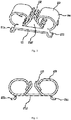
Fig. 2 is a sectional view of the electrical connector of the LED light shown inFig. 1 after assembling; -
Fig. 3 is a perspective view of an output terminal of the electrical connector of the LED light shown inFig. 1 ; -
Fig. 4 is a sectional view of the output terminal shown inFig. 2 . - The present invention will be described in detail below in conjunction with particular embodiments.
-
Fig. 1 is a perspective exploded view of a first embodiment of an electrical connector of an LED light of the present invention. The electrical connector of the LED light is used for realizing an electrical connection between alight source board 30 and adriver board 40 of the LED light. The electrical connector of the LED light includes aninput terminal 10 and anoutput terminal 20, one end of theinput terminal 10 is fixed on thedriver board 40 of the LED light and is electrically connected with thedriver board 40. - Referring to
Fig. 3 , theoutput terminal 20 includes a conductive end 21, anelastic clamping portion 22, and an abutting portion 23. Theelastic clamping portion 22 and the abutting portion 23 are provided on the conductive end 21, and in this embodiment, theelastic clamping portion 22 and the abutting portion 23 are both integrally provided on the conductive end 21. And the conductive end 21 is made of metal material integrally. - Referring to
Fig. 2 to Fig. 4 , the conductive end 21 includes aconductive leg 211, the conductive end 21 is fixed onto and electrically connected with thelight source board 30 via theconductive leg 211. Usually, theconductive leg 211 is welded on thelight source board 30. - A bottom of the
elastic clamping portion 22 is integrally connected to the conductive end 21, and a top of theelastic clamping portion 22 is obliquely bent in a direction away from the conductive end 21. In this embodiment, theelastic clamping portion 22 is in number of two, these elastic clamping portions are symmetrically disposed opposite to each other, and form a structure in a shape of Chinese character for "8", and these elastic clamping portions elastically abuts against two side walls of theinput terminal 10, respectively. The conductive end 21 is further provided thereon with athrough hole 212, theseelastic clamping portions 22 are symmetrically provided at both sides of the throughhole 212, and theinput terminal 10 passes through the through hole (212) so as to be electrically connected with theseelastic clamping portions 22. - In this embodiment, the abutting portion 23 is of an elastic sheet structure, with the structure bent to have a shape of Chinese character for "door". One end of the abutting portion 23 is fixed on the conductive end 21, and the other end of the abutting portion 23 abuts, after being bent, against the
elastic clamping portion 22. A bottom of the other end of the abutting portion 23 abuts against theelastic clamping portion 22. Each of theelastic clamping portion 22 is provided thereon with openings, so that each of theelastic clamping portion 22 forms a comb-shaped structure. The comb-shaped structures of theseelastic clamping portions 22 are alternatively disposed. In this way, in one aspect, the elasticity of theelastic clamping portion 22 is improved; and in another aspect, when theinput terminal 10 abuts against theelastic clamping portions 22, the comb-shaped structures can be interlaced so as to provide electrical contact at multiple points, which improves the reliability of the electrical connection. - In an assembled state, the other end of the
input terminal 10 elastically abuts against one side of theelastic clamping portion 22, and the abutting portion 23 abuts against the other side of the elastic clamping portion. In this embodiment, the other end of theinput terminal 10 elastically abuts against the top of theelastic clamping portion 22. And the abutting portion 23 abuts against a middle part of theelastic clamping portion 22. In this way, theinput terminal 10 is spaced apart from the abutting portion 23, so that a deformation range of theelastic clamping portion 22 can be effectively limited.. In summary, the electrical connector of the LED light is provided with theinput terminal 10 and theoutput terminal 20, thedriver board 40, theinput terminal 10, theoutput terminal 20, and thelight source board 30 are electrically connected in order. In particular, the output terminal is provided with theelastic clamping portion 22 and the abutting portion 23. In the assembled state, the other end of theinput terminal 10 elastically abuts against one side of theelastic clamping portion 22, and the abutting portion 23 abuts against the other side of the elastic clamping portion. In this way, the abutting portion 23 can provide a reaction force for theelastic clamping portion 22, so that an electrical contact between the elastic clamping portion 2 and theinput terminal 10 is tighter and is not easy to loosen, and enabling the electrical connector of the LED light to have the advantages of simple structure and high reliability. - In practice, the abutting portion 23 may be of a rigid structure, one end of the abutting portion 23 is fixed on the conductive end 21, and the other end of the abutting portion 23 abuts against the middle part of the
elastic clamping portion 22. Which can also serve the function of limiting the deformation range of theelastic clamping portion 22. - The foregoing just gives preferable embodiments of the present invention, rather than limiting the present invention. Any modifications, equivalent substations and improvements, made within the principle of the present invention, shall be covered by the scope of protection of the present set of claims.
-
- 10
- input terminal
- 20
- output terminal
- 30
- light source board
- 40
- driver board
- 21
- conductive end
- 211
- conductive leg
- 212
- through hole
- 22
- elastic clamping portion
- 23
- abutting portion
Claims (8)
- An electrical assembly for a LED light, the assembly comprising a light source board (30) and a driver board (40) of the LED light and an electrical connector configured to perform an electrical connection between the light source board (30) and the driver board (40), the electrical connector comprising an input terminal (10) and an output terminal (20), wherein one end of the input terminal (10) is fixed on the driver board (40) of the LED light and is electrically connected with the driver board (40), the output terminal (20) comprises a conductive end (21), an elastic clamping portion (22) and an abutting portion (23), the conductive end (21) comprises a conductive leg (211), the conductive end (21) is fixed onto and electrically connected with the light source board (30) via the conductive leg (211), the elastic clamping portion (22) and the abutting portion (23) are provided on the conductive end (21), and in an assembled state, the other end of the input terminal (10) elastically abuts against one side of the elastic clamping portion (22) and the abutting portion (23) abuts against the other side of the elastic clamping portion (22), wherein the elastic clamping portion (22) and the abutting portion (23) are both integrally provided on the conductive end (21), and a bottom of the elastic clamping portion (22) is connected to the conductive end (21), and a top of the elastic clamping portion (22) is obliquely bent in a direction away from the conductive end (21).
- The electrical assembly according to claim 1, characterized in that the other end of the input terminal (10) elastically abuts against the top of the elastic clamping portion (22), and the abutting portion (23) abuts against a middle part of the elastic clamping portion (22).
- The electrical assembly according to claim 1 or 2, characterized in that the abutting portion (23) is of a rigid structure, one end of the abutting portion (23) is fixed on the conductive end (21), and the other end of the abutting portion (23) abuts against the middle part of the elastic clamping portion (22).
- The electrical assembly according to any one of claims 1-2, characterized in that the abutting portion (23) is of an elastic sheet structure, one end of the abutting portion (23) is fixed on the conductive end (21), and the other end of the abutting portion (23) abuts, after being bent, against the elastic clamping portion (22).
- The electrical assembly according to claim 4, characterized in that the abutting portion (23) is of a bending structure in a shape of Chinese character for "door" , and a bottom of the other end of the abutting portion (23) abuts against the elastic clamping portion (22).
- The electrical assembly according to any one of claims 1-5, characterized in that the elastic clamping portion (22) is in number of two, the elastic clamping portions (22) are disposed opposite to each other and form a structure in a shape of Chinese character for "8", and the elastic clamping portions (22) elastically abut against two side walls of the input terminal (10), respectively.
- The electrical assembly according to claim 6, characterized in that the conductive end (21) is further provided thereon with a through hole (212), the elastic clamping portions (22) are symmetrically provided at both sides of the through hole (212), and the input terminal (10) passes through the through hole (212) so as to be electrically connected with the elastic clamping portions (22).
- The electrical assembly according to claim 6, characterized in that each of the elastic clamping portion (22) is provided thereon with openings so that each of the elastic clamping portion (22) forms a comb-shaped structure.
Priority Applications (1)
| Application Number | Priority Date | Filing Date | Title |
|---|---|---|---|
| PL16834545T PL3273157T3 (en) | 2015-08-10 | 2016-07-15 | Led lamp electrical connection member |
Applications Claiming Priority (2)
| Application Number | Priority Date | Filing Date | Title |
|---|---|---|---|
| CN201510483673.1A CN105180115B (en) | 2015-08-10 | 2015-08-10 | Electrical connectors for LED lights |
| PCT/CN2016/090152 WO2017024921A1 (en) | 2015-08-10 | 2016-07-15 | Led lamp electrical connection member |
Publications (3)
| Publication Number | Publication Date |
|---|---|
| EP3273157A1 EP3273157A1 (en) | 2018-01-24 |
| EP3273157A4 EP3273157A4 (en) | 2018-03-21 |
| EP3273157B1 true EP3273157B1 (en) | 2020-08-19 |
Family
ID=54902388
Family Applications (1)
| Application Number | Title | Priority Date | Filing Date |
|---|---|---|---|
| EP16834545.2A Active EP3273157B1 (en) | 2015-08-10 | 2016-07-15 | Led lamp electrical connection member |
Country Status (6)
| Country | Link |
|---|---|
| US (3) | US10060612B2 (en) |
| EP (1) | EP3273157B1 (en) |
| CN (1) | CN105180115B (en) |
| ES (1) | ES2819535T3 (en) |
| PL (1) | PL3273157T3 (en) |
| WO (1) | WO2017024921A1 (en) |
Families Citing this family (6)
| Publication number | Priority date | Publication date | Assignee | Title |
|---|---|---|---|---|
| CN104676513A (en) * | 2015-03-27 | 2015-06-03 | 立达信绿色照明股份有限公司 | Electric connection structure of lamp holder |
| CN105180115B (en) | 2015-08-10 | 2018-05-01 | 漳州立达信光电子科技有限公司 | Electrical connectors for LED lights |
| CN105180116A (en) * | 2015-08-11 | 2015-12-23 | 漳州立达信光电子科技有限公司 | electrical connector |
| CN105351896B (en) * | 2015-11-27 | 2022-10-25 | 漳州立达信光电子科技有限公司 | Electrical connector |
| JP7243245B2 (en) * | 2019-02-07 | 2023-03-22 | 株式会社島津製作所 | Light source device and holography observation device |
| CN111706838A (en) * | 2020-05-28 | 2020-09-25 | 赛尔富电子有限公司 | A plug-in structure and a lamp using the plug-in structure |
Family Cites Families (42)
| Publication number | Priority date | Publication date | Assignee | Title |
|---|---|---|---|---|
| US3915544A (en) * | 1974-11-05 | 1975-10-28 | Gen Motors Corp | Electrical terminal |
| US4640561A (en) * | 1985-11-15 | 1987-02-03 | Ford Motor Company | Flexible printed circuit connector |
| US6089880A (en) * | 1996-11-28 | 2000-07-18 | Denso Corporation | Electric connector arrangement |
| DE20203083U1 (en) * | 2002-02-27 | 2002-05-29 | Tyco Electronics AMP GmbH, 64625 Bensheim | Electric contact |
| US6715900B2 (en) * | 2002-05-17 | 2004-04-06 | A L Lightech, Inc. | Light source arrangement |
| DE10315668B4 (en) * | 2002-08-28 | 2007-06-06 | Conrad Stanztechnik Gmbh | terminal |
| TWM293185U (en) * | 2006-01-17 | 2006-07-01 | Jr-Shian Wu | Power-connecting structure of LED lamp transformation used in cars |
| US20070243740A1 (en) * | 2006-01-19 | 2007-10-18 | Karton Richard L | Socket assembly |
| CN101162816B (en) * | 2007-09-13 | 2010-09-01 | 番禺得意精密电子工业有限公司 | Electric connector |
| US7581965B1 (en) * | 2008-05-01 | 2009-09-01 | Commscope, Inc. Of North Carolina | Bottom entry interconnection element for connecting components to a circuit board |
| US8337214B2 (en) * | 2009-11-13 | 2012-12-25 | Cree, Inc. | Electrical connectors and light emitting device package and methods of assembling the same |
| TWM409543U (en) * | 2010-01-13 | 2011-08-11 | Molex Inc | Holder assembly |
| US8596821B2 (en) * | 2010-06-08 | 2013-12-03 | Cree, Inc. | LED light bulbs |
| JP4908616B2 (en) * | 2010-07-28 | 2012-04-04 | 日本航空電子工業株式会社 | Connector and lighting device |
| JP4963736B2 (en) * | 2010-10-28 | 2012-06-27 | 日本航空電子工業株式会社 | Lighting device |
| JP2015038810A (en) * | 2011-01-12 | 2015-02-26 | イリソ電子工業株式会社 | Connector |
| ITVR20110006U1 (en) * | 2011-03-01 | 2012-09-02 | Marco Bologna | ADAPTER PARTICULARLY FOR LIGHT LIGHTING DIODES IN COMMERCIAL LAMPHOLDERS. |
| US8708525B2 (en) * | 2011-03-02 | 2014-04-29 | Texas Instruments Incorporated | Light emitting diode light bulb and incandescent lamp conversion apparatus |
| CN103547849B (en) * | 2011-04-29 | 2018-04-17 | 亮锐控股有限公司 | LED light device with lower part heat dissipation structure |
| US8872417B2 (en) * | 2011-06-22 | 2014-10-28 | Gt Biomescilt Light Limited | Socket adaptor having AC-DC convertor for LED lamp |
| US8142227B1 (en) * | 2011-07-06 | 2012-03-27 | Fang Puo Kuo | Multifunctional base for energy saving lamps |
| US9951909B2 (en) * | 2012-04-13 | 2018-04-24 | Cree, Inc. | LED lamp |
| US8757839B2 (en) * | 2012-04-13 | 2014-06-24 | Cree, Inc. | Gas cooled LED lamp |
| US9410687B2 (en) * | 2012-04-13 | 2016-08-09 | Cree, Inc. | LED lamp with filament style LED assembly |
| US8628342B2 (en) * | 2012-06-04 | 2014-01-14 | Rv Lighting | Swivel adaptor |
| CN103047625B (en) * | 2012-12-21 | 2016-03-23 | 厦门立达信照明有限公司 | Electrical connector and use the LED of this electrical connector |
| CN203147664U (en) * | 2012-12-21 | 2013-08-21 | 厦门立明光电有限公司 | Electrical connector and LED lamp adopting same |
| DE102013101408B4 (en) * | 2013-02-13 | 2021-01-14 | Wago Verwaltungsgesellschaft Mbh | Spring-loaded clamping element and connecting terminal |
| US20160025319A1 (en) * | 2013-03-11 | 2016-01-28 | Molex, Llc | Holder, holder assembly and led assembly using holder assembly |
| JP6022992B2 (en) * | 2013-04-23 | 2016-11-09 | 日本航空電子工業株式会社 | Connector and lighting device |
| US9093809B2 (en) * | 2013-08-26 | 2015-07-28 | Abl Ip Holding Llc | Theft deterrents for solid state lamps |
| DE102013109802A1 (en) * | 2013-09-09 | 2015-03-12 | Phoenix Contact Gmbh & Co. Kg | clamping spring |
| CN203771347U (en) * | 2014-01-26 | 2014-08-13 | 立达信绿色照明股份有限公司 | Electric connector of LED lamp |
| US9518704B2 (en) * | 2014-02-25 | 2016-12-13 | Cree, Inc. | LED lamp with an interior electrical connection |
| US9618163B2 (en) * | 2014-06-17 | 2017-04-11 | Cree, Inc. | LED lamp with electronics board to submount connection |
| CN204100183U (en) * | 2014-07-31 | 2015-01-14 | 厦门广泓工贸有限公司 | A kind of simple and easy firm type metal female end and apply the LED of this metal female end |
| CN104676513A (en) * | 2015-03-27 | 2015-06-03 | 立达信绿色照明股份有限公司 | Electric connection structure of lamp holder |
| CN204986912U (en) * | 2015-08-10 | 2016-01-20 | 漳州立达信光电子科技有限公司 | Electric connector of LED lamp |
| CN105180115B (en) | 2015-08-10 | 2018-05-01 | 漳州立达信光电子科技有限公司 | Electrical connectors for LED lights |
| US10591150B2 (en) * | 2015-12-03 | 2020-03-17 | Xiamen Eco Lighting Co. Ltd. | Integrated electrical connector device structure of LED light |
| CN109519900A (en) * | 2018-11-28 | 2019-03-26 | 漳州立达信光电子科技有限公司 | Light source board heat radiation structure and lamps and lanterns |
| US10928044B2 (en) * | 2019-04-26 | 2021-02-23 | Xiamen Eco Lighting Co. Ltd. | Downlight apparatus |
-
2015
- 2015-08-10 CN CN201510483673.1A patent/CN105180115B/en active Active
-
2016
- 2016-07-15 ES ES16834545T patent/ES2819535T3/en active Active
- 2016-07-15 US US15/508,456 patent/US10060612B2/en active Active
- 2016-07-15 EP EP16834545.2A patent/EP3273157B1/en active Active
- 2016-07-15 WO PCT/CN2016/090152 patent/WO2017024921A1/en not_active Ceased
- 2016-07-15 PL PL16834545T patent/PL3273157T3/en unknown
-
2018
- 2018-07-23 US US16/042,427 patent/US10557624B2/en active Active
-
2020
- 2020-01-06 US US16/735,433 patent/US11149934B2/en active Active
Non-Patent Citations (1)
| Title |
|---|
| None * |
Also Published As
| Publication number | Publication date |
|---|---|
| EP3273157A4 (en) | 2018-03-21 |
| CN105180115B (en) | 2018-05-01 |
| US20200141566A1 (en) | 2020-05-07 |
| US20180328578A1 (en) | 2018-11-15 |
| US10557624B2 (en) | 2020-02-11 |
| EP3273157A1 (en) | 2018-01-24 |
| WO2017024921A1 (en) | 2017-02-16 |
| CN105180115A (en) | 2015-12-23 |
| PL3273157T3 (en) | 2021-05-04 |
| US20170276338A1 (en) | 2017-09-28 |
| ES2819535T3 (en) | 2021-04-16 |
| US11149934B2 (en) | 2021-10-19 |
| US10060612B2 (en) | 2018-08-28 |
Similar Documents
| Publication | Publication Date | Title |
|---|---|---|
| EP2937628B1 (en) | Electric connecting piece and led lamp using same | |
| CN203147664U (en) | Electrical connector and LED lamp adopting same | |
| US10253962B2 (en) | Connector and LED lighting device including the connector | |
| EP3273157A1 (en) | Led lamp electrical connection member | |
| KR20090091779A (en) | Low Profile Surface Mount Fork-In Connectors | |
| CN102474032A (en) | Contact spring for plug connector socket | |
| EP3273158B1 (en) | Electrical connector | |
| USRE48806E1 (en) | Spring lock clip for coupling a circuit board to an electrical base | |
| EP3273159B1 (en) | Integrated electric connection structure for led lamp | |
| EP3407428A1 (en) | Metal leaf spring structure of electrical connection terminal | |
| US10651571B2 (en) | Metal leaf spring protection structure of electrical connection terminal | |
| CN204986912U (en) | Electric connector of LED lamp | |
| CN106500064B (en) | Electric connector and LED lighting device | |
| US7402066B2 (en) | Low insertion force socket with lead-in mechanism background of the invention | |
| JP5930089B1 (en) | Conductive terminal | |
| CN205174291U (en) | electrical connector | |
| CN207199868U (en) | Push-type electrical connector for surface mounting and lamps using the push-type electrical connector | |
| CN106352308B (en) | LED electric connector and LED lamp | |
| JP2003045535A (en) | Terminal fitting | |
| CN210668740U (en) | electrical connector | |
| CN213691709U (en) | Copper binding post with pre-positioning mechanism | |
| WO2012096407A1 (en) | Shield case of receptacle | |
| KR200324360Y1 (en) | electricity connector | |
| EP3561959B1 (en) | Connector | |
| CN201303101Y (en) | Electrical connector |
Legal Events
| Date | Code | Title | Description |
|---|---|---|---|
| STAA | Information on the status of an ep patent application or granted ep patent |
Free format text: STATUS: THE INTERNATIONAL PUBLICATION HAS BEEN MADE |
|
| PUAI | Public reference made under article 153(3) epc to a published international application that has entered the european phase |
Free format text: ORIGINAL CODE: 0009012 |
|
| STAA | Information on the status of an ep patent application or granted ep patent |
Free format text: STATUS: REQUEST FOR EXAMINATION WAS MADE |
|
| 17P | Request for examination filed |
Effective date: 20171013 |
|
| AK | Designated contracting states |
Kind code of ref document: A1 Designated state(s): AL AT BE BG CH CY CZ DE DK EE ES FI FR GB GR HR HU IE IS IT LI LT LU LV MC MK MT NL NO PL PT RO RS SE SI SK SM TR |
|
| AX | Request for extension of the european patent |
Extension state: BA ME |
|
| A4 | Supplementary search report drawn up and despatched |
Effective date: 20180216 |
|
| RIC1 | Information provided on ipc code assigned before grant |
Ipc: H01R 13/11 20060101ALN20180212BHEP Ipc: F21Y 115/10 20160101ALN20180212BHEP Ipc: H01R 12/71 20110101ALI20180212BHEP Ipc: F21K 9/238 20160101ALI20180212BHEP Ipc: H01R 12/72 20110101ALN20180212BHEP Ipc: F21V 23/00 20150101ALI20180212BHEP Ipc: H01R 12/73 20110101ALI20180212BHEP Ipc: H01R 13/18 20060101ALI20180212BHEP Ipc: H01R 12/57 20110101ALN20180212BHEP Ipc: F21V 23/06 20060101AFI20180212BHEP |
|
| DAV | Request for validation of the european patent (deleted) | ||
| DAX | Request for extension of the european patent (deleted) | ||
| STAA | Information on the status of an ep patent application or granted ep patent |
Free format text: STATUS: EXAMINATION IS IN PROGRESS |
|
| 17Q | First examination report despatched |
Effective date: 20190228 |
|
| RIC1 | Information provided on ipc code assigned before grant |
Ipc: H01R 12/73 20110101ALI20200306BHEP Ipc: H01R 13/11 20060101ALN20200306BHEP Ipc: F21Y 115/10 20160101ALN20200306BHEP Ipc: F21K 9/238 20160101ALI20200306BHEP Ipc: H01R 12/72 20110101ALN20200306BHEP Ipc: H01R 12/71 20110101ALI20200306BHEP Ipc: H01R 13/18 20060101ALI20200306BHEP Ipc: H01R 12/57 20110101ALN20200306BHEP Ipc: F21V 23/00 20150101ALI20200306BHEP Ipc: F21V 23/06 20060101AFI20200306BHEP |
|
| GRAP | Despatch of communication of intention to grant a patent |
Free format text: ORIGINAL CODE: EPIDOSNIGR1 |
|
| STAA | Information on the status of an ep patent application or granted ep patent |
Free format text: STATUS: GRANT OF PATENT IS INTENDED |
|
| RIC1 | Information provided on ipc code assigned before grant |
Ipc: F21V 23/06 20060101AFI20200402BHEP Ipc: H01R 13/11 20060101ALN20200402BHEP Ipc: H01R 12/57 20110101ALN20200402BHEP Ipc: F21V 23/00 20150101ALI20200402BHEP Ipc: H01R 13/18 20060101ALI20200402BHEP Ipc: F21Y 115/10 20160101ALN20200402BHEP Ipc: H01R 12/71 20110101ALI20200402BHEP Ipc: H01R 12/72 20110101ALN20200402BHEP Ipc: F21K 9/238 20160101ALI20200402BHEP Ipc: H01R 12/73 20110101ALI20200402BHEP |
|
| INTG | Intention to grant announced |
Effective date: 20200424 |
|
| GRAS | Grant fee paid |
Free format text: ORIGINAL CODE: EPIDOSNIGR3 |
|
| GRAA | (expected) grant |
Free format text: ORIGINAL CODE: 0009210 |
|
| STAA | Information on the status of an ep patent application or granted ep patent |
Free format text: STATUS: THE PATENT HAS BEEN GRANTED |
|
| AK | Designated contracting states |
Kind code of ref document: B1 Designated state(s): AL AT BE BG CH CY CZ DE DK EE ES FI FR GB GR HR HU IE IS IT LI LT LU LV MC MK MT NL NO PL PT RO RS SE SI SK SM TR |
|
| REG | Reference to a national code |
Ref country code: CH Ref legal event code: EP |
|
| REG | Reference to a national code |
Ref country code: DE Ref legal event code: R096 Ref document number: 602016042474 Country of ref document: DE |
|
| REG | Reference to a national code |
Ref country code: AT Ref legal event code: REF Ref document number: 1304342 Country of ref document: AT Kind code of ref document: T Effective date: 20200915 |
|
| REG | Reference to a national code |
Ref country code: IE Ref legal event code: FG4D |
|
| REG | Reference to a national code |
Ref country code: NL Ref legal event code: FP |
|
| REG | Reference to a national code |
Ref country code: NO Ref legal event code: T2 Effective date: 20200819 |
|
| REG | Reference to a national code |
Ref country code: FI Ref legal event code: FGE |
|
| REG | Reference to a national code |
Ref country code: RO Ref legal event code: EPE |
|
| REG | Reference to a national code |
Ref country code: LT Ref legal event code: MG4D |
|
| PG25 | Lapsed in a contracting state [announced via postgrant information from national office to epo] |
Ref country code: PT Free format text: LAPSE BECAUSE OF FAILURE TO SUBMIT A TRANSLATION OF THE DESCRIPTION OR TO PAY THE FEE WITHIN THE PRESCRIBED TIME-LIMIT Effective date: 20201221 Ref country code: SE Free format text: LAPSE BECAUSE OF FAILURE TO SUBMIT A TRANSLATION OF THE DESCRIPTION OR TO PAY THE FEE WITHIN THE PRESCRIBED TIME-LIMIT Effective date: 20200819 Ref country code: HR Free format text: LAPSE BECAUSE OF FAILURE TO SUBMIT A TRANSLATION OF THE DESCRIPTION OR TO PAY THE FEE WITHIN THE PRESCRIBED TIME-LIMIT Effective date: 20200819 Ref country code: BG Free format text: LAPSE BECAUSE OF FAILURE TO SUBMIT A TRANSLATION OF THE DESCRIPTION OR TO PAY THE FEE WITHIN THE PRESCRIBED TIME-LIMIT Effective date: 20201119 Ref country code: LT Free format text: LAPSE BECAUSE OF FAILURE TO SUBMIT A TRANSLATION OF THE DESCRIPTION OR TO PAY THE FEE WITHIN THE PRESCRIBED TIME-LIMIT Effective date: 20200819 Ref country code: GR Free format text: LAPSE BECAUSE OF FAILURE TO SUBMIT A TRANSLATION OF THE DESCRIPTION OR TO PAY THE FEE WITHIN THE PRESCRIBED TIME-LIMIT Effective date: 20201120 |
|
| REG | Reference to a national code |
Ref country code: AT Ref legal event code: MK05 Ref document number: 1304342 Country of ref document: AT Kind code of ref document: T Effective date: 20200819 |
|
| PG25 | Lapsed in a contracting state [announced via postgrant information from national office to epo] |
Ref country code: LV Free format text: LAPSE BECAUSE OF FAILURE TO SUBMIT A TRANSLATION OF THE DESCRIPTION OR TO PAY THE FEE WITHIN THE PRESCRIBED TIME-LIMIT Effective date: 20200819 Ref country code: RS Free format text: LAPSE BECAUSE OF FAILURE TO SUBMIT A TRANSLATION OF THE DESCRIPTION OR TO PAY THE FEE WITHIN THE PRESCRIBED TIME-LIMIT Effective date: 20200819 Ref country code: IS Free format text: LAPSE BECAUSE OF FAILURE TO SUBMIT A TRANSLATION OF THE DESCRIPTION OR TO PAY THE FEE WITHIN THE PRESCRIBED TIME-LIMIT Effective date: 20201219 |
|
| REG | Reference to a national code |
Ref country code: ES Ref legal event code: FG2A Ref document number: 2819535 Country of ref document: ES Kind code of ref document: T3 Effective date: 20210416 |
|
| PG25 | Lapsed in a contracting state [announced via postgrant information from national office to epo] |
Ref country code: EE Free format text: LAPSE BECAUSE OF FAILURE TO SUBMIT A TRANSLATION OF THE DESCRIPTION OR TO PAY THE FEE WITHIN THE PRESCRIBED TIME-LIMIT Effective date: 20200819 Ref country code: SM Free format text: LAPSE BECAUSE OF FAILURE TO SUBMIT A TRANSLATION OF THE DESCRIPTION OR TO PAY THE FEE WITHIN THE PRESCRIBED TIME-LIMIT Effective date: 20200819 Ref country code: DK Free format text: LAPSE BECAUSE OF FAILURE TO SUBMIT A TRANSLATION OF THE DESCRIPTION OR TO PAY THE FEE WITHIN THE PRESCRIBED TIME-LIMIT Effective date: 20200819 |
|
| REG | Reference to a national code |
Ref country code: DE Ref legal event code: R097 Ref document number: 602016042474 Country of ref document: DE |
|
| PG25 | Lapsed in a contracting state [announced via postgrant information from national office to epo] |
Ref country code: AL Free format text: LAPSE BECAUSE OF FAILURE TO SUBMIT A TRANSLATION OF THE DESCRIPTION OR TO PAY THE FEE WITHIN THE PRESCRIBED TIME-LIMIT Effective date: 20200819 Ref country code: AT Free format text: LAPSE BECAUSE OF FAILURE TO SUBMIT A TRANSLATION OF THE DESCRIPTION OR TO PAY THE FEE WITHIN THE PRESCRIBED TIME-LIMIT Effective date: 20200819 |
|
| PLBE | No opposition filed within time limit |
Free format text: ORIGINAL CODE: 0009261 |
|
| STAA | Information on the status of an ep patent application or granted ep patent |
Free format text: STATUS: NO OPPOSITION FILED WITHIN TIME LIMIT |
|
| PG25 | Lapsed in a contracting state [announced via postgrant information from national office to epo] |
Ref country code: SK Free format text: LAPSE BECAUSE OF FAILURE TO SUBMIT A TRANSLATION OF THE DESCRIPTION OR TO PAY THE FEE WITHIN THE PRESCRIBED TIME-LIMIT Effective date: 20200819 |
|
| 26N | No opposition filed |
Effective date: 20210520 |
|
| PG25 | Lapsed in a contracting state [announced via postgrant information from national office to epo] |
Ref country code: SI Free format text: LAPSE BECAUSE OF FAILURE TO SUBMIT A TRANSLATION OF THE DESCRIPTION OR TO PAY THE FEE WITHIN THE PRESCRIBED TIME-LIMIT Effective date: 20200819 |
|
| REG | Reference to a national code |
Ref country code: CH Ref legal event code: PL |
|
| PG25 | Lapsed in a contracting state [announced via postgrant information from national office to epo] |
Ref country code: MC Free format text: LAPSE BECAUSE OF FAILURE TO SUBMIT A TRANSLATION OF THE DESCRIPTION OR TO PAY THE FEE WITHIN THE PRESCRIBED TIME-LIMIT Effective date: 20200819 |
|
| PG25 | Lapsed in a contracting state [announced via postgrant information from national office to epo] |
Ref country code: LI Free format text: LAPSE BECAUSE OF NON-PAYMENT OF DUE FEES Effective date: 20210731 Ref country code: CH Free format text: LAPSE BECAUSE OF NON-PAYMENT OF DUE FEES Effective date: 20210731 |
|
| PG25 | Lapsed in a contracting state [announced via postgrant information from national office to epo] |
Ref country code: LU Free format text: LAPSE BECAUSE OF NON-PAYMENT OF DUE FEES Effective date: 20210715 |
|
| PG25 | Lapsed in a contracting state [announced via postgrant information from national office to epo] |
Ref country code: IE Free format text: LAPSE BECAUSE OF NON-PAYMENT OF DUE FEES Effective date: 20210715 |
|
| PG25 | Lapsed in a contracting state [announced via postgrant information from national office to epo] |
Ref country code: HU Free format text: LAPSE BECAUSE OF FAILURE TO SUBMIT A TRANSLATION OF THE DESCRIPTION OR TO PAY THE FEE WITHIN THE PRESCRIBED TIME-LIMIT; INVALID AB INITIO Effective date: 20160715 |
|
| PG25 | Lapsed in a contracting state [announced via postgrant information from national office to epo] |
Ref country code: CY Free format text: LAPSE BECAUSE OF FAILURE TO SUBMIT A TRANSLATION OF THE DESCRIPTION OR TO PAY THE FEE WITHIN THE PRESCRIBED TIME-LIMIT Effective date: 20200819 |
|
| PG25 | Lapsed in a contracting state [announced via postgrant information from national office to epo] |
Ref country code: MK Free format text: LAPSE BECAUSE OF FAILURE TO SUBMIT A TRANSLATION OF THE DESCRIPTION OR TO PAY THE FEE WITHIN THE PRESCRIBED TIME-LIMIT Effective date: 20200819 |
|
| PG25 | Lapsed in a contracting state [announced via postgrant information from national office to epo] |
Ref country code: TR Free format text: LAPSE BECAUSE OF FAILURE TO SUBMIT A TRANSLATION OF THE DESCRIPTION OR TO PAY THE FEE WITHIN THE PRESCRIBED TIME-LIMIT Effective date: 20200819 |
|
| PG25 | Lapsed in a contracting state [announced via postgrant information from national office to epo] |
Ref country code: MT Free format text: LAPSE BECAUSE OF FAILURE TO SUBMIT A TRANSLATION OF THE DESCRIPTION OR TO PAY THE FEE WITHIN THE PRESCRIBED TIME-LIMIT Effective date: 20200819 |
|
| PGFP | Annual fee paid to national office [announced via postgrant information from national office to epo] |
Ref country code: FI Payment date: 20250627 Year of fee payment: 10 |
|
| PGFP | Annual fee paid to national office [announced via postgrant information from national office to epo] |
Ref country code: GB Payment date: 20250626 Year of fee payment: 10 |
|
| PGFP | Annual fee paid to national office [announced via postgrant information from national office to epo] |
Ref country code: NO Payment date: 20250627 Year of fee payment: 10 |
|
| PGFP | Annual fee paid to national office [announced via postgrant information from national office to epo] |
Ref country code: FR Payment date: 20250626 Year of fee payment: 10 |
|
| PGFP | Annual fee paid to national office [announced via postgrant information from national office to epo] |
Ref country code: NL Payment date: 20250627 Year of fee payment: 10 |
|
| PGFP | Annual fee paid to national office [announced via postgrant information from national office to epo] |
Ref country code: ES Payment date: 20250821 Year of fee payment: 10 |
|
| PGFP | Annual fee paid to national office [announced via postgrant information from national office to epo] |
Ref country code: DE Payment date: 20250627 Year of fee payment: 10 |
|
| PGFP | Annual fee paid to national office [announced via postgrant information from national office to epo] |
Ref country code: PL Payment date: 20250704 Year of fee payment: 10 Ref country code: IT Payment date: 20250627 Year of fee payment: 10 |
|
| PGFP | Annual fee paid to national office [announced via postgrant information from national office to epo] |
Ref country code: BE Payment date: 20250627 Year of fee payment: 10 |
|
| PGFP | Annual fee paid to national office [announced via postgrant information from national office to epo] |
Ref country code: CZ Payment date: 20250708 Year of fee payment: 10 |
|
| PGFP | Annual fee paid to national office [announced via postgrant information from national office to epo] |
Ref country code: RO Payment date: 20250701 Year of fee payment: 10 |