EP3273154A1 - Auto aligning module for lighting application - Google Patents
Auto aligning module for lighting application Download PDFInfo
- Publication number
- EP3273154A1 EP3273154A1 EP17181030.2A EP17181030A EP3273154A1 EP 3273154 A1 EP3273154 A1 EP 3273154A1 EP 17181030 A EP17181030 A EP 17181030A EP 3273154 A1 EP3273154 A1 EP 3273154A1
- Authority
- EP
- European Patent Office
- Prior art keywords
- led system
- led
- housing
- interior space
- alignment module
- Prior art date
- Legal status (The legal status is an assumption and is not a legal conclusion. Google has not performed a legal analysis and makes no representation as to the accuracy of the status listed.)
- Granted
Links
- 238000000034 method Methods 0.000 claims description 15
- 238000004873 anchoring Methods 0.000 claims description 13
- 239000000463 material Substances 0.000 claims description 13
- 230000003287 optical effect Effects 0.000 description 2
- 239000013536 elastomeric material Substances 0.000 description 1
- 238000005516 engineering process Methods 0.000 description 1
- 239000012530 fluid Substances 0.000 description 1
- 238000012986 modification Methods 0.000 description 1
- 230000004048 modification Effects 0.000 description 1
- 238000009420 retrofitting Methods 0.000 description 1
- 230000011664 signaling Effects 0.000 description 1
- 230000003068 static effect Effects 0.000 description 1
- 230000002123 temporal effect Effects 0.000 description 1
Images



Classifications
-
- F—MECHANICAL ENGINEERING; LIGHTING; HEATING; WEAPONS; BLASTING
- F21—LIGHTING
- F21V—FUNCTIONAL FEATURES OR DETAILS OF LIGHTING DEVICES OR SYSTEMS THEREOF; STRUCTURAL COMBINATIONS OF LIGHTING DEVICES WITH OTHER ARTICLES, NOT OTHERWISE PROVIDED FOR
- F21V15/00—Protecting lighting devices from damage
- F21V15/04—Resilient mountings, e.g. shock absorbers
-
- B—PERFORMING OPERATIONS; TRANSPORTING
- B61—RAILWAYS
- B61L—GUIDING RAILWAY TRAFFIC; ENSURING THE SAFETY OF RAILWAY TRAFFIC
- B61L9/00—Illumination specially adapted for points, form signals, or gates
- B61L9/04—Illumination specially adapted for points, form signals, or gates electric
-
- F—MECHANICAL ENGINEERING; LIGHTING; HEATING; WEAPONS; BLASTING
- F21—LIGHTING
- F21K—NON-ELECTRIC LIGHT SOURCES USING LUMINESCENCE; LIGHT SOURCES USING ELECTROCHEMILUMINESCENCE; LIGHT SOURCES USING CHARGES OF COMBUSTIBLE MATERIAL; LIGHT SOURCES USING SEMICONDUCTOR DEVICES AS LIGHT-GENERATING ELEMENTS; LIGHT SOURCES NOT OTHERWISE PROVIDED FOR
- F21K9/00—Light sources using semiconductor devices as light-generating elements, e.g. using light-emitting diodes [LED] or lasers
- F21K9/20—Light sources comprising attachment means
- F21K9/23—Retrofit light sources for lighting devices with a single fitting for each light source, e.g. for substitution of incandescent lamps with bayonet or threaded fittings
- F21K9/235—Details of bases or caps, i.e. the parts that connect the light source to a fitting; Arrangement of components within bases or caps
-
- F—MECHANICAL ENGINEERING; LIGHTING; HEATING; WEAPONS; BLASTING
- F21—LIGHTING
- F21K—NON-ELECTRIC LIGHT SOURCES USING LUMINESCENCE; LIGHT SOURCES USING ELECTROCHEMILUMINESCENCE; LIGHT SOURCES USING CHARGES OF COMBUSTIBLE MATERIAL; LIGHT SOURCES USING SEMICONDUCTOR DEVICES AS LIGHT-GENERATING ELEMENTS; LIGHT SOURCES NOT OTHERWISE PROVIDED FOR
- F21K9/00—Light sources using semiconductor devices as light-generating elements, e.g. using light-emitting diodes [LED] or lasers
- F21K9/20—Light sources comprising attachment means
- F21K9/23—Retrofit light sources for lighting devices with a single fitting for each light source, e.g. for substitution of incandescent lamps with bayonet or threaded fittings
- F21K9/237—Details of housings or cases, i.e. the parts between the light-generating element and the bases; Arrangement of components within housings or cases
-
- F—MECHANICAL ENGINEERING; LIGHTING; HEATING; WEAPONS; BLASTING
- F21—LIGHTING
- F21V—FUNCTIONAL FEATURES OR DETAILS OF LIGHTING DEVICES OR SYSTEMS THEREOF; STRUCTURAL COMBINATIONS OF LIGHTING DEVICES WITH OTHER ARTICLES, NOT OTHERWISE PROVIDED FOR
- F21V21/00—Supporting, suspending, or attaching arrangements for lighting devices; Hand grips
- F21V21/14—Adjustable mountings
- F21V21/26—Pivoted arms
-
- F—MECHANICAL ENGINEERING; LIGHTING; HEATING; WEAPONS; BLASTING
- F21—LIGHTING
- F21W—INDEXING SCHEME ASSOCIATED WITH SUBCLASSES F21K, F21L, F21S and F21V, RELATING TO USES OR APPLICATIONS OF LIGHTING DEVICES OR SYSTEMS
- F21W2111/00—Use or application of lighting devices or systems for signalling, marking or indicating, not provided for in codes F21W2102/00 – F21W2107/00
-
- F—MECHANICAL ENGINEERING; LIGHTING; HEATING; WEAPONS; BLASTING
- F21—LIGHTING
- F21W—INDEXING SCHEME ASSOCIATED WITH SUBCLASSES F21K, F21L, F21S and F21V, RELATING TO USES OR APPLICATIONS OF LIGHTING DEVICES OR SYSTEMS
- F21W2131/00—Use or application of lighting devices or systems not provided for in codes F21W2102/00-F21W2121/00
- F21W2131/10—Outdoor lighting
-
- F—MECHANICAL ENGINEERING; LIGHTING; HEATING; WEAPONS; BLASTING
- F21—LIGHTING
- F21Y—INDEXING SCHEME ASSOCIATED WITH SUBCLASSES F21K, F21L, F21S and F21V, RELATING TO THE FORM OR THE KIND OF THE LIGHT SOURCES OR OF THE COLOUR OF THE LIGHT EMITTED
- F21Y2115/00—Light-generating elements of semiconductor light sources
- F21Y2115/10—Light-emitting diodes [LED]
-
- G—PHYSICS
- G08—SIGNALLING
- G08G—TRAFFIC CONTROL SYSTEMS
- G08G1/00—Traffic control systems for road vehicles
- G08G1/09—Arrangements for giving variable traffic instructions
- G08G1/095—Traffic lights
Definitions
- Embodiments generally relate to a lighting system including a housing, an LED system, and an alignment module supported in the housing to mount the LED system in an interior space in the housing, dampen vibration(s) of the LED system in the interior space, and automatically align a focal point of the LED system.
- a lightening system for example, may be applicable for a traffic/rail signal.
- an incandescent bulb In current incandescent traffic/rail signaling, in an interior space of the incandescent traffic/rail signal housing, an incandescent bulb is mechanically held in place by a socket base.
- the socket base is not suitable for anchoring the LED system (LED source and PSU). LED systems require additional anchorage points that are not available in these housing making retrofit applications challenging.
- a lighting system 100 in accordance with embodiments includes a housing 200, an LED system 300 mounted in the housing 200, and an alignment module 400 supported in the housing 200 to mount the LED system 300 in the housing 200, dampen vibration of the LED system in the interior space, and automatically align a focal point of the LED system.
- a lightening system 100 for example, may be applicable for a traffic/rail signal.
- the housing 200 defines an interior space 210 which is to receive the LED system 300 and the alignment module 400. As illustrated in FIGS. 1 , 2 , 4 , and 5 , the housing 200 may be utilized as a housing for a traffic/rail signal. Embodiment, however, are not limited thereto. The housing 200 may be for other industrial and/or domestic applications. While the housing 200 and the interior space 210 thereof are illustrated here having a specific structural geometry, embodiments are not limited thereto. In accordance with embodiments, the housing 200 and the interior space 210 thereof may be configured in any manner that permits practice of embodiments set forth herein.
- the LED system 300 may comprise a conventional configuration that includes an LED module comprising an LED lamp having one or more LEDs connected to a power supply.
- the alignment module 400 permits the LED system 300 to be retrofitted into pre-existing incandescent housing 200.
- the alignment module 400 prevents pivoting or shifting of the reflector of the LED module of the LED system 300 within the housing 200 in the event outside forces causes rotation or movement of the housing 200. Consequently, the alignment module 400 serves to automatically align a focal point of the LED module during rotation, shifting, or movement of the housing 200. This may be done by preventing pivoting of the reflector of the LED module in the housing 200. In that way, the LED system 300 may be maintained, via the alignment module 400, in a static position in the housing 200. The overall optical performance of the LED system 300, therefore, is enhanced.
- the alignment module 400 may be positioned in the interior space at a plurality of predetermined anchoring points A, B, C.
- the alignment module 400 may be, for example, rotatably positioned in the interior space at the predetermined anchoring points A, B, C.
- the predetermined anchoring points may include a base of the incandescent bulb, a first region, e.g., a pin, of the LED system 300, and a second region, e.g., the lens of the LED system 300.
- the alignment module 400 may comprise a main body 410, an arm 420 that is to extend from the main body 410 to connect to the LED system 300, and at least one bias mechanism 430 to bias the alignment module 400 against at least one interior wall of the housing 200 during rotation or pivoting of the alignment module 400.
- the arm 420 may comprise a pivoting arm that permits that is to extend from the main body 410 to connect to the LED system 300, and at least one bias mechanism 430 to bias the alignment module 400 against at least one interior wall of the housing 200 during rotation or pivoting of the alignment module 400 about a pivot axis defined by the arm 420.
- the alignment module 400 may comprise a main body 410 that is connected directly to the LED system 300, and at least one bias mechanism 430 to bias the alignment module 400 against at least one interior wall of the housing 200 during rotation or pivoting of the alignment module 400.
- the main body 410 may be composed of one or more materials having dampening characteristics. Such materials may comprise elastomeric materials.
- the main body 410 while illustrated having a generally rectangular cross-section, may take any structural configuration that permits practice of embodiments set forth herein.
- the pivot arm 420 may be composed of a material having dampening characteristics. Such a material may comprise an elastomeric material.
- the pivot arm 420 may be composed of the same material(s) as the main body 410. Alternatively, the pivot arm 420 may be composed of different material(s) than the main body 410.
- the main body 410 and pivot arm 420 may form a single, uniform structure. Alternatively, the pivot arm 420 may be mechanically connected to the main body 410.
- each bias mechanism 430 is to exert a biasing force against the surface of the interior wall.
- the bias mechanism 430 may comprise one or more springs placed at various regions of the alignment module 400.
- One such spring may be located at the pivot arm 420 while at least spring may be located on the main body 410.
- the spring in the pivot arm 420 may comprise a plate spring, while the springs located on the main body 410 may comprise torsion springs or conical springs.
- Other types of springs may be used in a manner that permits practice of embodiments set forth herein.
- Example 1 may include a lighting system, comprising: a housing defining an interior space; an LED system arranged in the interior space; and an alignment module supported in the housing to support the LED system in the interior space, dampen vibration of the LED system in the interior space, and automatically align a focal point of the LED system.
- a lighting system comprising: a housing defining an interior space; an LED system arranged in the interior space; and an alignment module supported in the housing to support the LED system in the interior space, dampen vibration of the LED system in the interior space, and automatically align a focal point of the LED system.
- Example 2 may include the lighting system of Example 1, wherein the alignment module is arranged in the interior space at a plurality of predetermined anchoring points.
- Example 3 may include the lighting system of Example 2, wherein the predetermined anchoring points comprise a base of an incandescent bulb, a pin of the LED system, and a lens of the LED system.
- Example 4 may include the lighting system of Example 1, wherein the alignment module comprises: a main body; a pivot arm extending from the main body, and which is connected to the LED system; and at least one bias mechanism to bias the alignment module against an interior wall of the housing during rotation thereof.
- the alignment module comprises: a main body; a pivot arm extending from the main body, and which is connected to the LED system; and at least one bias mechanism to bias the alignment module against an interior wall of the housing during rotation thereof.
- Example 5 may include the lighting system of Example 4, wherein the pivot arm defines a pivot axis about which the alignment module is to rotate in the housing.
- Example 6 may include the lighting system of Example 4, wherein the pivot arm comprises the at least one bias mechanism.
- Example 7 may include the lighting system of Example 6, wherein the at least one bias mechanism comprises spring.
- Example 8 may include the lighting system of Example 6, wherein the main body is composed of a material having dampening characteristics.
- Example 9 may include a system comprising: an LED lamp; and an alignment module supported to mount an LED lamp, dampen vibration of the LED system in the interior space, and automatically align a focal point of the LED system.
- Example 10 may include the system of Example 9, wherein the alignment module is arranged in an interior space at a plurality of predetermined anchoring points.
- Example 11 may include the system of Example 9, wherein the alignment module comprises: a main body; a pivot arm extending from the main body, and which is connected to the LED system; and at least one bias mechanism to bias the alignment body against a surface.
- the alignment module comprises: a main body; a pivot arm extending from the main body, and which is connected to the LED system; and at least one bias mechanism to bias the alignment body against a surface.
- Example 12 may include the system of Example 11, wherein the pivot arm defines a pivot axis about which the alignment module is to rotate.
- Example 13 may include the system of Example 11, wherein the pivot arm comprises the at least one bias mechanism.
- Example 14 may include the system of Example 11, wherein the at least one bias mechanism comprises a spring.
- Example 15 may include the system of Example 11, wherein the main body is composed of a material having dampening characteristics.
- Example 16 may include method comprising: supporting an LED system in an interior space of a housing; and automatically aligning, during operation of the LED system, a focal point of the LED system during movement of the housing.
- Example 17 may include the method of Example 16, wherein the LED system is mechanically supported in the interior space.
- Example 18 may include the method of Example 16, further comprising dampening vibrations, during operation of the LED system, of the LED system in the interior space.
- Example 19 may include the method of Example 16, wherein automatically aligning the focal point of the LED system comprises applying at least one bias force against at least one interior wall of the housing.
- Example 20 may include the method of Example 16, wherein automatically aligning, during operation of the LED system comprises preventing pivoting of the LED system.
- Coupled may be used herein to refer to any type of relationship, direct or indirect, between the components in question, and may apply to electrical, mechanical, fluid, optical, electromagnetic, electromechanical or other connections.
- first”, second, etc. may be used herein only to facilitate discussion, and carry no particular temporal or chronological significance unless otherwise indicated.
- a list of items joined by the term “one or more of” or “at least one of” may mean any combination of the listed terms.
- the phrases “one or more of A, B or C” may mean A; B; C; A and B; A and C; B and C; or A, B and C.
- a list of items joined by the term “and so forth”, “and so on”, or “etc.” may mean any combination of the listed terms as well any combination with other terms.
Landscapes
- Engineering & Computer Science (AREA)
- General Engineering & Computer Science (AREA)
- Physics & Mathematics (AREA)
- Microelectronics & Electronic Packaging (AREA)
- Optics & Photonics (AREA)
- Mechanical Engineering (AREA)
- Non-Portable Lighting Devices Or Systems Thereof (AREA)
- Arrangements Of Lighting Devices For Vehicle Interiors, Mounting And Supporting Thereof, Circuits Therefore (AREA)
Abstract
Description
- Embodiments generally relate to a lighting system including a housing, an LED system, and an alignment module supported in the housing to mount the LED system in an interior space in the housing, dampen vibration(s) of the LED system in the interior space, and automatically align a focal point of the LED system. Such a lightening system, for example, may be applicable for a traffic/rail signal.
- In current incandescent traffic/rail signaling, in an interior space of the incandescent traffic/rail signal housing, an incandescent bulb is mechanically held in place by a socket base.
- When retrofitting the current incandescent traffic/rail signal housing to utilize light-emitting diode (LED) technology, the socket base is not suitable for anchoring the LED system (LED source and PSU). LED systems require additional anchorage points that are not available in these housing making retrofit applications challenging.
- The various advantages of embodiments will become apparent to one skilled in the art by reading the following specification and appended claims, and by referencing the following drawings, in which:
-
FIG. 1 illustrates a back view of a lighting system, in accordance with embodiments. -
FIG. 2 illustrates a side view of the lighting system, in accordance with embodiments. -
FIG. 3 illustrates a back view of an alignment module of the lighting system, in accordance with embodiments. -
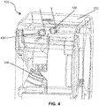
FIG. 4 illustrates a side view of a lighting system, in accordance with embodiments. -
FIG. 5 illustrates a back view of a lighting system during a pivoting of the alignment module, in accordance with embodiments. - As illustrated in
FIGS. 1 through 5 , alighting system 100 in accordance with embodiments includes ahousing 200, anLED system 300 mounted in thehousing 200, and analignment module 400 supported in thehousing 200 to mount theLED system 300 in thehousing 200, dampen vibration of the LED system in the interior space, and automatically align a focal point of the LED system. Such alightening system 100, for example, may be applicable for a traffic/rail signal. - The
housing 200 defines aninterior space 210 which is to receive theLED system 300 and thealignment module 400. As illustrated inFIGS. 1 ,2 ,4 , and5 , thehousing 200 may be utilized as a housing for a traffic/rail signal. Embodiment, however, are not limited thereto. Thehousing 200 may be for other industrial and/or domestic applications. While thehousing 200 and theinterior space 210 thereof are illustrated here having a specific structural geometry, embodiments are not limited thereto. In accordance with embodiments, thehousing 200 and theinterior space 210 thereof may be configured in any manner that permits practice of embodiments set forth herein. - The
LED system 300 may comprise a conventional configuration that includes an LED module comprising an LED lamp having one or more LEDs connected to a power supply. - As illustrated in
FIG. 3 , thealignment module 400 permits theLED system 300 to be retrofitted into pre-existingincandescent housing 200. In this way, thealignment module 400 prevents pivoting or shifting of the reflector of the LED module of theLED system 300 within thehousing 200 in the event outside forces causes rotation or movement of thehousing 200. Consequently, thealignment module 400 serves to automatically align a focal point of the LED module during rotation, shifting, or movement of thehousing 200. This may be done by preventing pivoting of the reflector of the LED module in thehousing 200. In that way, theLED system 300 may be maintained, via thealignment module 400, in a static position in thehousing 200. The overall optical performance of theLED system 300, therefore, is enhanced. - The
alignment module 400 may be positioned in the interior space at a plurality of predetermined anchoring points A, B, C. Alternatively, thealignment module 400 may be, for example, rotatably positioned in the interior space at the predetermined anchoring points A, B, C. For example, the predetermined anchoring points may include a base of the incandescent bulb, a first region, e.g., a pin, of theLED system 300, and a second region, e.g., the lens of theLED system 300. - In accordance with embodiments, the
alignment module 400 may comprise amain body 410, anarm 420 that is to extend from themain body 410 to connect to theLED system 300, and at least onebias mechanism 430 to bias thealignment module 400 against at least one interior wall of thehousing 200 during rotation or pivoting of thealignment module 400. - In accordance with embodiments, alternatively, the
arm 420 may comprise a pivoting arm that permits that is to extend from themain body 410 to connect to theLED system 300, and at least onebias mechanism 430 to bias thealignment module 400 against at least one interior wall of thehousing 200 during rotation or pivoting of thealignment module 400 about a pivot axis defined by thearm 420. - In accordance with embodiments, the
alignment module 400 may comprise amain body 410 that is connected directly to theLED system 300, and at least onebias mechanism 430 to bias thealignment module 400 against at least one interior wall of thehousing 200 during rotation or pivoting of thealignment module 400. - The
main body 410 may be composed of one or more materials having dampening characteristics. Such materials may comprise elastomeric materials. Themain body 410, while illustrated having a generally rectangular cross-section, may take any structural configuration that permits practice of embodiments set forth herein. - The
pivot arm 420 may be composed of a material having dampening characteristics. Such a material may comprise an elastomeric material. Thepivot arm 420 may be composed of the same material(s) as themain body 410. Alternatively, thepivot arm 420 may be composed of different material(s) than themain body 410. Themain body 410 andpivot arm 420 may form a single, uniform structure. Alternatively, thepivot arm 420 may be mechanically connected to themain body 410. - Each
bias mechanism 430 is to exert a biasing force against the surface of the interior wall. In accordance with embodiments, thebias mechanism 430 may comprise one or more springs placed at various regions of thealignment module 400. One such spring may be located at thepivot arm 420 while at least spring may be located on themain body 410. For example, the spring in thepivot arm 420 may comprise a plate spring, while the springs located on themain body 410 may comprise torsion springs or conical springs. Other types of springs may be used in a manner that permits practice of embodiments set forth herein. - Example 1 may include a lighting system, comprising: a housing defining an interior space; an LED system arranged in the interior space; and an alignment module supported in the housing to support the LED system in the interior space, dampen vibration of the LED system in the interior space, and automatically align a focal point of the LED system.
- Example 2 may include the lighting system of Example 1, wherein the alignment module is arranged in the interior space at a plurality of predetermined anchoring points.
- Example 3 may include the lighting system of Example 2, wherein the predetermined anchoring points comprise a base of an incandescent bulb, a pin of the LED system, and a lens of the LED system.
- Example 4 may include the lighting system of Example 1, wherein the alignment module comprises: a main body; a pivot arm extending from the main body, and which is connected to the LED system; and at least one bias mechanism to bias the alignment module against an interior wall of the housing during rotation thereof.
- Example 5 may include the lighting system of Example 4, wherein the pivot arm defines a pivot axis about which the alignment module is to rotate in the housing.
- Example 6 may include the lighting system of Example 4, wherein the pivot arm comprises the at least one bias mechanism.
- Example 7 may include the lighting system of Example 6, wherein the at least one bias mechanism comprises spring.
- Example 8 may include the lighting system of Example 6, wherein the main body is composed of a material having dampening characteristics.
- Example 9 may include a system comprising: an LED lamp; and an alignment module supported to mount an LED lamp, dampen vibration of the LED system in the interior space, and automatically align a focal point of the LED system.
- Example 10 may include the system of Example 9, wherein the alignment module is arranged in an interior space at a plurality of predetermined anchoring points.
- Example 11 may include the system of Example 9, wherein the alignment module comprises: a main body; a pivot arm extending from the main body, and which is connected to the LED system; and at least one bias mechanism to bias the alignment body against a surface.
- Example 12 may include the system of Example 11, wherein the pivot arm defines a pivot axis about which the alignment module is to rotate.
- Example 13 may include the system of Example 11, wherein the pivot arm comprises the at least one bias mechanism.
- Example 14 may include the system of Example 11, wherein the at least one bias mechanism comprises a spring.
- Example 15 may include the system of Example 11, wherein the main body is composed of a material having dampening characteristics.
- Example 16 may include method comprising: supporting an LED system in an interior space of a housing; and automatically aligning, during operation of the LED system, a focal point of the LED system during movement of the housing.
- Example 17 may include the method of Example 16, wherein the LED system is mechanically supported in the interior space.
- Example 18 may include the method of Example 16, further comprising dampening vibrations, during operation of the LED system, of the LED system in the interior space.
- Example 19 may include the method of Example 16, wherein automatically aligning the focal point of the LED system comprises applying at least one bias force against at least one interior wall of the housing.
- Example 20 may include the method of Example 16, wherein automatically aligning, during operation of the LED system comprises preventing pivoting of the LED system.
- The term "coupled" may be used herein to refer to any type of relationship, direct or indirect, between the components in question, and may apply to electrical, mechanical, fluid, optical, electromagnetic, electromechanical or other connections. In addition, the terms "first", "second", etc. may be used herein only to facilitate discussion, and carry no particular temporal or chronological significance unless otherwise indicated.
- As used in this application and in the claims, a list of items joined by the term "one or more of" or "at least one of" may mean any combination of the listed terms. For example, the phrases "one or more of A, B or C" may mean A; B; C; A and B; A and C; B and C; or A, B and C. In addition, a list of items joined by the term "and so forth", "and so on", or "etc." may mean any combination of the listed terms as well any combination with other terms.
- Those skilled in the art will appreciate from the foregoing description that the broad techniques of the embodiments may be implemented in a variety of forms. Therefore, while the embodiments have been described in connection with particular examples thereof, the true scope of the embodiments should not be so limited since other modifications will become apparent to the skilled practitioner upon a study of the drawings, specification, and following claims.
- Various aspects and embodiments of the present invention are defined by the following clauses:
- 1. A lighting system, comprising:
- a housing defining an interior space;
- an LED system arranged in the interior space; and
- an alignment module supported in the housing to support the LED system in the interior space, dampen vibration of the LED system in the interior space, and automatically align a focal point of the LED system.
- 2. The lighting system of clause 1, wherein the alignment module is arranged in the interior space at a plurality of predetermined anchoring points.
- 3. The lighting system of clause 2, wherein the predetermined anchoring points comprise a base of an incandescent bulb, a pin of the LED system, and a lens of the LED system.
- 4. The lighting system of clause 1, wherein the alignment module comprises:
- a main body;
- a pivot arm extending from the main body, and which is connected to the LED system; and
- at least one bias mechanism to bias the alignment module against an interior wall of the housing during rotation thereof.
- 5. The lighting system of clause 4, wherein the pivot arm defines a pivot axis about which the alignment module is to rotate in the housing.
- 6. The lighting system of clause 4, wherein the pivot arm comprises the at least one bias mechanism.
- 7. The lighting system of clause 6, wherein the at least one bias mechanism comprises spring.
- 8. The lighting system of clause 6, wherein the main body is composed of a material having dampening characteristics.
- 9. A system, comprising:
- an LED lamp; and
- an alignment module supported to mount an LED lamp, dampen vibration of the LED system in the interior space, and automatically align a focal point of the LED system.
- 10. The system of clause 9, wherein the alignment module is arranged in an interior space at a plurality of predetermined anchoring points.
- 11. The system of clause 9, wherein the alignment module comprises:
- a main body;
- a pivot arm extending from the main body, and which is connected to the LED system; and
- at least one bias mechanism to bias the alignment body against a surface.
- 12. The system of clause 11, wherein the pivot arm defines a pivot axis about which the alignment module is to rotate.
- 13. The system of clause 11, wherein the pivot arm comprises the at least one bias mechanism.
- 14. The system of clause 11, wherein the at least one bias mechanism comprises a spring.
- 15. The system of clause 11, wherein the main body is composed of a material having dampening characteristics.
- 16. A method, comprising:
- supporting an LED system in an interior space of a housing; and
- automatically aligning, during operation of the LED system, a focal point of the LED system during movement of the housing.
- 17. The method of clause 16, wherein the LED system is mechanically supported in the interior space.
- 18. The method of clause 16, further comprising dampening vibrations, during operation of the LED system, of the LED system in the interior space.
- 19. The method of clause 16, wherein automatically aligning the focal point of the LED system comprises applying at least one bias force against at least one interior wall of the housing.
- 20. The method of clause 16, wherein automatically aligning, during operation of the LED system comprises preventing pivoting of the LED system.
Claims (15)
- A lighting system (100), comprising:a housing (200) defining an interior space;an LED system (300) arranged in the interior space; andan alignment module (400) supported in the housing (200) to support the LED system (300) in the interior space, dampen vibration of the LED system (300) in the interior space, and automatically align a focal point of the LED system (300).
- The lighting system (100) of claim 1, wherein the alignment module (400) is arranged in the interior space at a plurality of predetermined anchoring points (A, B, C) and/or wherein the predetermined anchoring points (A, B, C) comprise a base of an incandescent bulb, a pin of the LED system (300), and a lens of the LED system (300).
- The lighting system (100) of claim 1 or claim 2, wherein the alignment module (400) comprises:a main body (410);a pivot arm (420) extending from the main body (410), and which is connected to the LED system (300); andat least one bias mechanism (430) to bias the alignment module (400) against an interior wall of the housing (200) during rotation thereof.
- The lighting system (100) of claim 3, wherein the pivot arm (420) defines a pivot axis about which the alignment module (400) is to rotate in the housing (200).
- The lighting system (100) of claim 3 or claim 4, wherein the pivot arm (420) comprises the at least one bias mechanism (430) and/or wherein the at least one bias mechanism (430) comprises spring.
- The lighting system (100) of any one of claims 3 to 5, wherein the main body (410) is composed of a material having dampening characteristics.
- A system (100), comprising:an LED lamp; andan alignment module (400) supported to mount an LED lamp, dampen vibration of the LED system (300) in the interior space, and automatically align a focal point of the LED system (300).
- The system (100) of claim 7, wherein the alignment module (400) is arranged in an interior space at a plurality of predetermined anchoring points (A, B, C).
- The system (100) of claim 7 or claim 8, wherein the alignment module (400) comprises:a main body (410);a pivot arm (420) extending from the main body (410), and which is connected to the LED system (300); andat least one bias mechanism (430) to bias the alignment body against a surface.
- The system (100) of claim 9, wherein the pivot arm (420) defines a pivot axis about which the alignment module (400) is to rotate and/or wherein the pivot arm (420) comprises the at least one bias mechanism (430).
- The system (100) of claim 9 or claim 10, wherein the at least one bias mechanism (430) comprises a spring and wherein the main body (410) is composed of a material having dampening characteristics.
- A method, comprising:supporting an LED system (300) in an interior space of a housing (200); andautomatically aligning, during operation of the LED system (300), a focal point of the LED system (300) during movement of the housing (200).
- The method of claim 12, wherein the LED system (300) is mechanically supported in the interior space.
- The method of claim 12 or claim 13, further comprising dampening vibrations, during operation of the LED system (300), of the LED system (300) in the interior space and wherein automatically aligning the focal point of the LED system (300) comprises applying at least one bias force against at least one interior wall of the housing (200).
- The method of any one of claims 12 to 14, wherein automatically aligning, during operation of the LED system (300) comprises preventing pivoting of the LED system (300).
Applications Claiming Priority (1)
| Application Number | Priority Date | Filing Date | Title |
|---|---|---|---|
| US15/215,629 US10557617B2 (en) | 2016-07-21 | 2016-07-21 | Auto aligning module for lighting application |
Publications (2)
| Publication Number | Publication Date |
|---|---|
| EP3273154A1 true EP3273154A1 (en) | 2018-01-24 |
| EP3273154B1 EP3273154B1 (en) | 2019-12-18 |
Family
ID=59337518
Family Applications (1)
| Application Number | Title | Priority Date | Filing Date |
|---|---|---|---|
| EP17181030.2A Active EP3273154B1 (en) | 2016-07-21 | 2017-07-12 | Auto aligning module for lighting application |
Country Status (3)
| Country | Link |
|---|---|
| US (1) | US10557617B2 (en) |
| EP (1) | EP3273154B1 (en) |
| CA (1) | CA2972447A1 (en) |
Citations (4)
| Publication number | Priority date | Publication date | Assignee | Title |
|---|---|---|---|---|
| US5099401A (en) * | 1990-07-08 | 1992-03-24 | Stanley Electric Co., Ltd. | Signal lighting fixture for vehicles |
| US20080089070A1 (en) * | 2006-10-12 | 2008-04-17 | Chin-Wen Wang | Led lamp module with adjustable illuminating angle |
| WO2015136542A1 (en) * | 2014-03-13 | 2015-09-17 | Valerann Ltd. | Dynamic road marker |
| CN103883986B (en) * | 2012-12-20 | 2016-02-10 | 深圳市海洋王照明工程有限公司 | Lamp installation bucket and comprise the aid-to-navigation light of this lamp installation bucket |
Family Cites Families (8)
| Publication number | Priority date | Publication date | Assignee | Title |
|---|---|---|---|---|
| US4345307A (en) * | 1978-08-21 | 1982-08-17 | Mayer William R | Rectangular headlamp retainer |
| US4345301A (en) * | 1981-02-23 | 1982-08-17 | Honeywell Inc. | Capacitive humidity transducer |
| US5207747A (en) * | 1991-04-12 | 1993-05-04 | Musco Corporation | Mobile lighting system |
| US6036336A (en) | 1998-05-08 | 2000-03-14 | Wu; Chen H. | Light emitting diode retrofitting lamps for illuminated traffic signs |
| US6911915B2 (en) | 2002-09-04 | 2005-06-28 | Leotek Electronics Corporation | Compact light emitting diode retrofit lamp and method for traffic signal lights |
| US20050030754A1 (en) | 2003-08-07 | 2005-02-10 | Licht Harold Jay | Systems, devices, and methods for mounting a light emitting diode |
| KR101013694B1 (en) | 2008-06-17 | 2011-02-10 | 김영애 | Traffic signal aids emitting light by self-generation |
| US10323832B2 (en) * | 2015-12-15 | 2019-06-18 | Wangs Alliance Corporation | LED lighting methods and apparatus |
-
2016
- 2016-07-21 US US15/215,629 patent/US10557617B2/en active Active
-
2017
- 2017-07-06 CA CA2972447A patent/CA2972447A1/en not_active Abandoned
- 2017-07-12 EP EP17181030.2A patent/EP3273154B1/en active Active
Patent Citations (4)
| Publication number | Priority date | Publication date | Assignee | Title |
|---|---|---|---|---|
| US5099401A (en) * | 1990-07-08 | 1992-03-24 | Stanley Electric Co., Ltd. | Signal lighting fixture for vehicles |
| US20080089070A1 (en) * | 2006-10-12 | 2008-04-17 | Chin-Wen Wang | Led lamp module with adjustable illuminating angle |
| CN103883986B (en) * | 2012-12-20 | 2016-02-10 | 深圳市海洋王照明工程有限公司 | Lamp installation bucket and comprise the aid-to-navigation light of this lamp installation bucket |
| WO2015136542A1 (en) * | 2014-03-13 | 2015-09-17 | Valerann Ltd. | Dynamic road marker |
Also Published As
| Publication number | Publication date |
|---|---|
| US10557617B2 (en) | 2020-02-11 |
| US20180023786A1 (en) | 2018-01-25 |
| CA2972447A1 (en) | 2018-01-21 |
| EP3273154B1 (en) | 2019-12-18 |
Similar Documents
| Publication | Publication Date | Title |
|---|---|---|
| US11493187B2 (en) | Recessed light-emitting diode lighting fixture | |
| JP5193383B1 (en) | Optical semiconductor lighting device | |
| RU151666U1 (en) | DEVICE FOR INSTALLING OPTICAL LENS OF LIGHTING ELEMENT | |
| CN104541099B (en) | For positioning the method to the object of light shaping | |
| KR101308394B1 (en) | Optical semiconductor based illuminating apparatus | |
| KR101040645B1 (en) | Recessed light fixtures | |
| KR20070034952A (en) | LED lamps with optical coupling directly in axial alignment | |
| CN104797458B (en) | Lighting module including a control device detachably held on a bracket | |
| CN109477631A (en) | Lighting device | |
| CN104685291A (en) | Light module with two or more reflectors for a motor vehicle | |
| CN105378378A (en) | One-button detachable LED lighting device | |
| CN104541098B (en) | For the optical module of motor vehicle | |
| CN104930428A (en) | Lighting and/or signalling unit comprising an adapter suitable for being housed in a light module of a motor vehicle | |
| CN101556028B (en) | Projection lamp | |
| CN106796009A (en) | Module for will include light source is positioned at the device on Optical devices | |
| CN113316698A (en) | Lighting device with positioning means for a vehicle | |
| CN102906493B (en) | lighting equipment | |
| KR101713040B1 (en) | Detachable lightening device | |
| EP3273154A1 (en) | Auto aligning module for lighting application | |
| CN101191609A (en) | Recessed Lighting Fixtures | |
| US20160153641A1 (en) | Retrofit kit for recessed light fixtures and retrofitting method | |
| CN101776223A (en) | Support and lamp for shockproof protection of easily detachable light source | |
| CN113613950A (en) | Light module holding device for light emitting unit, light module, and light emitting unit for vehicle | |
| JP6796767B2 (en) | lighting equipment | |
| EP4173892A1 (en) | Automotive luminous device |
Legal Events
| Date | Code | Title | Description |
|---|---|---|---|
| PUAI | Public reference made under article 153(3) epc to a published international application that has entered the european phase |
Free format text: ORIGINAL CODE: 0009012 |
|
| STAA | Information on the status of an ep patent application or granted ep patent |
Free format text: STATUS: THE APPLICATION HAS BEEN PUBLISHED |
|
| AK | Designated contracting states |
Kind code of ref document: A1 Designated state(s): AL AT BE BG CH CY CZ DE DK EE ES FI FR GB GR HR HU IE IS IT LI LT LU LV MC MK MT NL NO PL PT RO RS SE SI SK SM TR |
|
| AX | Request for extension of the european patent |
Extension state: BA ME |
|
| STAA | Information on the status of an ep patent application or granted ep patent |
Free format text: STATUS: REQUEST FOR EXAMINATION WAS MADE |
|
| 17P | Request for examination filed |
Effective date: 20180724 |
|
| RBV | Designated contracting states (corrected) |
Designated state(s): AL AT BE BG CH CY CZ DE DK EE ES FI FR GB GR HR HU IE IS IT LI LT LU LV MC MK MT NL NO PL PT RO RS SE SI SK SM TR |
|
| STAA | Information on the status of an ep patent application or granted ep patent |
Free format text: STATUS: EXAMINATION IS IN PROGRESS |
|
| 17Q | First examination report despatched |
Effective date: 20180921 |
|
| RIC1 | Information provided on ipc code assigned before grant |
Ipc: F21V 15/04 20060101AFI20190212BHEP Ipc: F21Y 115/10 20160101ALN20190212BHEP |
|
| RIC1 | Information provided on ipc code assigned before grant |
Ipc: F21Y 115/10 20160101ALN20190314BHEP Ipc: F21V 15/04 20060101AFI20190314BHEP |
|
| GRAP | Despatch of communication of intention to grant a patent |
Free format text: ORIGINAL CODE: EPIDOSNIGR1 |
|
| STAA | Information on the status of an ep patent application or granted ep patent |
Free format text: STATUS: GRANT OF PATENT IS INTENDED |
|
| INTG | Intention to grant announced |
Effective date: 20190702 |
|
| RIC1 | Information provided on ipc code assigned before grant |
Ipc: F21V 15/04 20060101AFI20190624BHEP Ipc: F21Y 115/10 20160101ALN20190624BHEP |
|
| GRAS | Grant fee paid |
Free format text: ORIGINAL CODE: EPIDOSNIGR3 |
|
| GRAA | (expected) grant |
Free format text: ORIGINAL CODE: 0009210 |
|
| STAA | Information on the status of an ep patent application or granted ep patent |
Free format text: STATUS: THE PATENT HAS BEEN GRANTED |
|
| AK | Designated contracting states |
Kind code of ref document: B1 Designated state(s): AL AT BE BG CH CY CZ DE DK EE ES FI FR GB GR HR HU IE IS IT LI LT LU LV MC MK MT NL NO PL PT RO RS SE SI SK SM TR |
|
| REG | Reference to a national code |
Ref country code: CH Ref legal event code: EP |
|
| REG | Reference to a national code |
Ref country code: IE Ref legal event code: FG4D |
|
| REG | Reference to a national code |
Ref country code: DE Ref legal event code: R096 Ref document number: 602017009778 Country of ref document: DE |
|
| REG | Reference to a national code |
Ref country code: AT Ref legal event code: REF Ref document number: 1215009 Country of ref document: AT Kind code of ref document: T Effective date: 20200115 |
|
| REG | Reference to a national code |
Ref country code: NL Ref legal event code: MP Effective date: 20191218 |
|
| PG25 | Lapsed in a contracting state [announced via postgrant information from national office to epo] |
Ref country code: FI Free format text: LAPSE BECAUSE OF FAILURE TO SUBMIT A TRANSLATION OF THE DESCRIPTION OR TO PAY THE FEE WITHIN THE PRESCRIBED TIME-LIMIT Effective date: 20191218 Ref country code: BG Free format text: LAPSE BECAUSE OF FAILURE TO SUBMIT A TRANSLATION OF THE DESCRIPTION OR TO PAY THE FEE WITHIN THE PRESCRIBED TIME-LIMIT Effective date: 20200318 Ref country code: LT Free format text: LAPSE BECAUSE OF FAILURE TO SUBMIT A TRANSLATION OF THE DESCRIPTION OR TO PAY THE FEE WITHIN THE PRESCRIBED TIME-LIMIT Effective date: 20191218 Ref country code: GR Free format text: LAPSE BECAUSE OF FAILURE TO SUBMIT A TRANSLATION OF THE DESCRIPTION OR TO PAY THE FEE WITHIN THE PRESCRIBED TIME-LIMIT Effective date: 20200319 Ref country code: NO Free format text: LAPSE BECAUSE OF FAILURE TO SUBMIT A TRANSLATION OF THE DESCRIPTION OR TO PAY THE FEE WITHIN THE PRESCRIBED TIME-LIMIT Effective date: 20200318 Ref country code: SE Free format text: LAPSE BECAUSE OF FAILURE TO SUBMIT A TRANSLATION OF THE DESCRIPTION OR TO PAY THE FEE WITHIN THE PRESCRIBED TIME-LIMIT Effective date: 20191218 Ref country code: LV Free format text: LAPSE BECAUSE OF FAILURE TO SUBMIT A TRANSLATION OF THE DESCRIPTION OR TO PAY THE FEE WITHIN THE PRESCRIBED TIME-LIMIT Effective date: 20191218 |
|
| REG | Reference to a national code |
Ref country code: LT Ref legal event code: MG4D |
|
| PG25 | Lapsed in a contracting state [announced via postgrant information from national office to epo] |
Ref country code: HR Free format text: LAPSE BECAUSE OF FAILURE TO SUBMIT A TRANSLATION OF THE DESCRIPTION OR TO PAY THE FEE WITHIN THE PRESCRIBED TIME-LIMIT Effective date: 20191218 Ref country code: RS Free format text: LAPSE BECAUSE OF FAILURE TO SUBMIT A TRANSLATION OF THE DESCRIPTION OR TO PAY THE FEE WITHIN THE PRESCRIBED TIME-LIMIT Effective date: 20191218 |
|
| PG25 | Lapsed in a contracting state [announced via postgrant information from national office to epo] |
Ref country code: AL Free format text: LAPSE BECAUSE OF FAILURE TO SUBMIT A TRANSLATION OF THE DESCRIPTION OR TO PAY THE FEE WITHIN THE PRESCRIBED TIME-LIMIT Effective date: 20191218 |
|
| PG25 | Lapsed in a contracting state [announced via postgrant information from national office to epo] |
Ref country code: NL Free format text: LAPSE BECAUSE OF FAILURE TO SUBMIT A TRANSLATION OF THE DESCRIPTION OR TO PAY THE FEE WITHIN THE PRESCRIBED TIME-LIMIT Effective date: 20191218 Ref country code: EE Free format text: LAPSE BECAUSE OF FAILURE TO SUBMIT A TRANSLATION OF THE DESCRIPTION OR TO PAY THE FEE WITHIN THE PRESCRIBED TIME-LIMIT Effective date: 20191218 Ref country code: RO Free format text: LAPSE BECAUSE OF FAILURE TO SUBMIT A TRANSLATION OF THE DESCRIPTION OR TO PAY THE FEE WITHIN THE PRESCRIBED TIME-LIMIT Effective date: 20191218 Ref country code: PT Free format text: LAPSE BECAUSE OF FAILURE TO SUBMIT A TRANSLATION OF THE DESCRIPTION OR TO PAY THE FEE WITHIN THE PRESCRIBED TIME-LIMIT Effective date: 20200513 Ref country code: CZ Free format text: LAPSE BECAUSE OF FAILURE TO SUBMIT A TRANSLATION OF THE DESCRIPTION OR TO PAY THE FEE WITHIN THE PRESCRIBED TIME-LIMIT Effective date: 20191218 |
|
| PG25 | Lapsed in a contracting state [announced via postgrant information from national office to epo] |
Ref country code: SM Free format text: LAPSE BECAUSE OF FAILURE TO SUBMIT A TRANSLATION OF THE DESCRIPTION OR TO PAY THE FEE WITHIN THE PRESCRIBED TIME-LIMIT Effective date: 20191218 Ref country code: IS Free format text: LAPSE BECAUSE OF FAILURE TO SUBMIT A TRANSLATION OF THE DESCRIPTION OR TO PAY THE FEE WITHIN THE PRESCRIBED TIME-LIMIT Effective date: 20200418 Ref country code: SK Free format text: LAPSE BECAUSE OF FAILURE TO SUBMIT A TRANSLATION OF THE DESCRIPTION OR TO PAY THE FEE WITHIN THE PRESCRIBED TIME-LIMIT Effective date: 20191218 |
|
| REG | Reference to a national code |
Ref country code: DE Ref legal event code: R097 Ref document number: 602017009778 Country of ref document: DE |
|
| REG | Reference to a national code |
Ref country code: AT Ref legal event code: MK05 Ref document number: 1215009 Country of ref document: AT Kind code of ref document: T Effective date: 20191218 |
|
| PLBE | No opposition filed within time limit |
Free format text: ORIGINAL CODE: 0009261 |
|
| STAA | Information on the status of an ep patent application or granted ep patent |
Free format text: STATUS: NO OPPOSITION FILED WITHIN TIME LIMIT |
|
| PG25 | Lapsed in a contracting state [announced via postgrant information from national office to epo] |
Ref country code: DK Free format text: LAPSE BECAUSE OF FAILURE TO SUBMIT A TRANSLATION OF THE DESCRIPTION OR TO PAY THE FEE WITHIN THE PRESCRIBED TIME-LIMIT Effective date: 20191218 Ref country code: ES Free format text: LAPSE BECAUSE OF FAILURE TO SUBMIT A TRANSLATION OF THE DESCRIPTION OR TO PAY THE FEE WITHIN THE PRESCRIBED TIME-LIMIT Effective date: 20191218 |
|
| 26N | No opposition filed |
Effective date: 20200921 |
|
| PG25 | Lapsed in a contracting state [announced via postgrant information from national office to epo] |
Ref country code: AT Free format text: LAPSE BECAUSE OF FAILURE TO SUBMIT A TRANSLATION OF THE DESCRIPTION OR TO PAY THE FEE WITHIN THE PRESCRIBED TIME-LIMIT Effective date: 20191218 Ref country code: SI Free format text: LAPSE BECAUSE OF FAILURE TO SUBMIT A TRANSLATION OF THE DESCRIPTION OR TO PAY THE FEE WITHIN THE PRESCRIBED TIME-LIMIT Effective date: 20191218 |
|
| PG25 | Lapsed in a contracting state [announced via postgrant information from national office to epo] |
Ref country code: IT Free format text: LAPSE BECAUSE OF FAILURE TO SUBMIT A TRANSLATION OF THE DESCRIPTION OR TO PAY THE FEE WITHIN THE PRESCRIBED TIME-LIMIT Effective date: 20191218 |
|
| REG | Reference to a national code |
Ref country code: DE Ref legal event code: R119 Ref document number: 602017009778 Country of ref document: DE |
|
| PG25 | Lapsed in a contracting state [announced via postgrant information from national office to epo] |
Ref country code: MC Free format text: LAPSE BECAUSE OF FAILURE TO SUBMIT A TRANSLATION OF THE DESCRIPTION OR TO PAY THE FEE WITHIN THE PRESCRIBED TIME-LIMIT Effective date: 20191218 Ref country code: PL Free format text: LAPSE BECAUSE OF FAILURE TO SUBMIT A TRANSLATION OF THE DESCRIPTION OR TO PAY THE FEE WITHIN THE PRESCRIBED TIME-LIMIT Effective date: 20191218 |
|
| REG | Reference to a national code |
Ref country code: CH Ref legal event code: PL |
|
| REG | Reference to a national code |
Ref country code: BE Ref legal event code: MM Effective date: 20200731 |
|
| PG25 | Lapsed in a contracting state [announced via postgrant information from national office to epo] |
Ref country code: CH Free format text: LAPSE BECAUSE OF NON-PAYMENT OF DUE FEES Effective date: 20200731 Ref country code: LI Free format text: LAPSE BECAUSE OF NON-PAYMENT OF DUE FEES Effective date: 20200731 Ref country code: LU Free format text: LAPSE BECAUSE OF NON-PAYMENT OF DUE FEES Effective date: 20200712 Ref country code: FR Free format text: LAPSE BECAUSE OF NON-PAYMENT OF DUE FEES Effective date: 20200731 |
|
| PG25 | Lapsed in a contracting state [announced via postgrant information from national office to epo] |
Ref country code: DE Free format text: LAPSE BECAUSE OF NON-PAYMENT OF DUE FEES Effective date: 20210202 Ref country code: BE Free format text: LAPSE BECAUSE OF NON-PAYMENT OF DUE FEES Effective date: 20200731 |
|
| PG25 | Lapsed in a contracting state [announced via postgrant information from national office to epo] |
Ref country code: IE Free format text: LAPSE BECAUSE OF NON-PAYMENT OF DUE FEES Effective date: 20200712 |
|
| PGFP | Annual fee paid to national office [announced via postgrant information from national office to epo] |
Ref country code: GB Payment date: 20210623 Year of fee payment: 5 |
|
| PG25 | Lapsed in a contracting state [announced via postgrant information from national office to epo] |
Ref country code: TR Free format text: LAPSE BECAUSE OF FAILURE TO SUBMIT A TRANSLATION OF THE DESCRIPTION OR TO PAY THE FEE WITHIN THE PRESCRIBED TIME-LIMIT Effective date: 20191218 Ref country code: MT Free format text: LAPSE BECAUSE OF FAILURE TO SUBMIT A TRANSLATION OF THE DESCRIPTION OR TO PAY THE FEE WITHIN THE PRESCRIBED TIME-LIMIT Effective date: 20191218 Ref country code: CY Free format text: LAPSE BECAUSE OF FAILURE TO SUBMIT A TRANSLATION OF THE DESCRIPTION OR TO PAY THE FEE WITHIN THE PRESCRIBED TIME-LIMIT Effective date: 20191218 |
|
| PG25 | Lapsed in a contracting state [announced via postgrant information from national office to epo] |
Ref country code: MK Free format text: LAPSE BECAUSE OF FAILURE TO SUBMIT A TRANSLATION OF THE DESCRIPTION OR TO PAY THE FEE WITHIN THE PRESCRIBED TIME-LIMIT Effective date: 20191218 |
|
| GBPC | Gb: european patent ceased through non-payment of renewal fee |
Effective date: 20220712 |
|
| PG25 | Lapsed in a contracting state [announced via postgrant information from national office to epo] |
Ref country code: GB Free format text: LAPSE BECAUSE OF NON-PAYMENT OF DUE FEES Effective date: 20220712 |