EP3273046A1 - Rocket fueling system and method of fueling a rocket - Google Patents
Rocket fueling system and method of fueling a rocket Download PDFInfo
- Publication number
- EP3273046A1 EP3273046A1 EP17181944.4A EP17181944A EP3273046A1 EP 3273046 A1 EP3273046 A1 EP 3273046A1 EP 17181944 A EP17181944 A EP 17181944A EP 3273046 A1 EP3273046 A1 EP 3273046A1
- Authority
- EP
- European Patent Office
- Prior art keywords
- rocket
- cryogen
- gas
- fuel
- insulated jacket
- Prior art date
- Legal status (The legal status is an assumption and is not a legal conclusion. Google has not performed a legal analysis and makes no representation as to the accuracy of the status listed.)
- Granted
Links
Images




Classifications
-
- B—PERFORMING OPERATIONS; TRANSPORTING
- B64—AIRCRAFT; AVIATION; COSMONAUTICS
- B64G—COSMONAUTICS; VEHICLES OR EQUIPMENT THEREFOR
- B64G5/00—Ground equipment for vehicles, e.g. starting towers, fuelling arrangements
-
- F—MECHANICAL ENGINEERING; LIGHTING; HEATING; WEAPONS; BLASTING
- F02—COMBUSTION ENGINES; HOT-GAS OR COMBUSTION-PRODUCT ENGINE PLANTS
- F02K—JET-PROPULSION PLANTS
- F02K9/00—Rocket-engine plants, i.e. plants carrying both fuel and oxidant therefor; Control thereof
- F02K9/42—Rocket-engine plants, i.e. plants carrying both fuel and oxidant therefor; Control thereof using liquid or gaseous propellants
- F02K9/44—Feeding propellants
-
- B—PERFORMING OPERATIONS; TRANSPORTING
- B64—AIRCRAFT; AVIATION; COSMONAUTICS
- B64G—COSMONAUTICS; VEHICLES OR EQUIPMENT THEREFOR
- B64G1/00—Cosmonautic vehicles
- B64G1/22—Parts of, or equipment specially adapted for fitting in or to, cosmonautic vehicles
- B64G1/40—Arrangements or adaptations of propulsion systems
- B64G1/401—Liquid propellant rocket engines
-
- B—PERFORMING OPERATIONS; TRANSPORTING
- B64—AIRCRAFT; AVIATION; COSMONAUTICS
- B64G—COSMONAUTICS; VEHICLES OR EQUIPMENT THEREFOR
- B64G1/00—Cosmonautic vehicles
- B64G1/22—Parts of, or equipment specially adapted for fitting in or to, cosmonautic vehicles
- B64G1/40—Arrangements or adaptations of propulsion systems
- B64G1/402—Propellant tanks; Feeding propellants
-
- F—MECHANICAL ENGINEERING; LIGHTING; HEATING; WEAPONS; BLASTING
- F02—COMBUSTION ENGINES; HOT-GAS OR COMBUSTION-PRODUCT ENGINE PLANTS
- F02K—JET-PROPULSION PLANTS
- F02K9/00—Rocket-engine plants, i.e. plants carrying both fuel and oxidant therefor; Control thereof
-
- F—MECHANICAL ENGINEERING; LIGHTING; HEATING; WEAPONS; BLASTING
- F02—COMBUSTION ENGINES; HOT-GAS OR COMBUSTION-PRODUCT ENGINE PLANTS
- F02K—JET-PROPULSION PLANTS
- F02K9/00—Rocket-engine plants, i.e. plants carrying both fuel and oxidant therefor; Control thereof
- F02K9/42—Rocket-engine plants, i.e. plants carrying both fuel and oxidant therefor; Control thereof using liquid or gaseous propellants
- F02K9/44—Feeding propellants
- F02K9/52—Injectors
-
- F—MECHANICAL ENGINEERING; LIGHTING; HEATING; WEAPONS; BLASTING
- F02—COMBUSTION ENGINES; HOT-GAS OR COMBUSTION-PRODUCT ENGINE PLANTS
- F02K—JET-PROPULSION PLANTS
- F02K9/00—Rocket-engine plants, i.e. plants carrying both fuel and oxidant therefor; Control thereof
- F02K9/42—Rocket-engine plants, i.e. plants carrying both fuel and oxidant therefor; Control thereof using liquid or gaseous propellants
- F02K9/44—Feeding propellants
- F02K9/56—Control
- F02K9/566—Control elements and safety devices, e.g. pressure relief valves
-
- F—MECHANICAL ENGINEERING; LIGHTING; HEATING; WEAPONS; BLASTING
- F02—COMBUSTION ENGINES; HOT-GAS OR COMBUSTION-PRODUCT ENGINE PLANTS
- F02K—JET-PROPULSION PLANTS
- F02K9/00—Rocket-engine plants, i.e. plants carrying both fuel and oxidant therefor; Control thereof
- F02K9/42—Rocket-engine plants, i.e. plants carrying both fuel and oxidant therefor; Control thereof using liquid or gaseous propellants
- F02K9/60—Constructional parts; Details not otherwise provided for
-
- F—MECHANICAL ENGINEERING; LIGHTING; HEATING; WEAPONS; BLASTING
- F02—COMBUSTION ENGINES; HOT-GAS OR COMBUSTION-PRODUCT ENGINE PLANTS
- F02K—JET-PROPULSION PLANTS
- F02K9/00—Rocket-engine plants, i.e. plants carrying both fuel and oxidant therefor; Control thereof
- F02K9/42—Rocket-engine plants, i.e. plants carrying both fuel and oxidant therefor; Control thereof using liquid or gaseous propellants
- F02K9/60—Constructional parts; Details not otherwise provided for
- F02K9/62—Combustion or thrust chambers
-
- F—MECHANICAL ENGINEERING; LIGHTING; HEATING; WEAPONS; BLASTING
- F02—COMBUSTION ENGINES; HOT-GAS OR COMBUSTION-PRODUCT ENGINE PLANTS
- F02K—JET-PROPULSION PLANTS
- F02K9/00—Rocket-engine plants, i.e. plants carrying both fuel and oxidant therefor; Control thereof
- F02K9/42—Rocket-engine plants, i.e. plants carrying both fuel and oxidant therefor; Control thereof using liquid or gaseous propellants
- F02K9/60—Constructional parts; Details not otherwise provided for
- F02K9/62—Combustion or thrust chambers
- F02K9/64—Combustion or thrust chambers having cooling arrangements
-
- F—MECHANICAL ENGINEERING; LIGHTING; HEATING; WEAPONS; BLASTING
- F02—COMBUSTION ENGINES; HOT-GAS OR COMBUSTION-PRODUCT ENGINE PLANTS
- F02K—JET-PROPULSION PLANTS
- F02K9/00—Rocket-engine plants, i.e. plants carrying both fuel and oxidant therefor; Control thereof
- F02K9/97—Rocket nozzles
- F02K9/972—Fluid cooling arrangements for nozzles
Definitions
- the present disclosure generally relates to rocket fueling systems, and more particularly to, methods and systems that provide for fueling a rocket by liquefying a gaseous rocket fuel in a fuel chamber of the rocket.
- Rockets are generally used to move payloads (e.g., satellites or astronauts) from the surface of the Earth to a desired orbit or trajectory.
- a rocket can launch a payload to orbit in outer space.
- the rocket can move the payload in a suborbital manner from one location to another.
- a rocket has a rocket engine that utilizes a rocket fuel to propel the rocket through the atmosphere and/or space.
- the rocket fuel is contained within the rocket throughout travel and, thus, the rocket must be fueled prior to launch. Fueling a rocket can be a potentially time consuming and costly process.
- existing techniques it can take a relatively long time to fuel a rocket with a liquid rocket fuel because, after the rocket is moved to a launch site, the rocket must be cooled to a temperature suitable for receiving the liquid rocket fuel (i.e., below a boiling point of the rocket fuel).
- existing techniques for fueling a rocket with a liquid rocket fuel generally involve storing relatively large quantities of highly combustible rocket fuel in temperature controlled environments for extended periods of time.
- a rocket fueling system includes an insulated jacket configured to removably couple to at least a portion of a rocket and form an enclosed space between the insulated jacket and the at least the portion of the rocket.
- the rocket fueling system also includes a cryogen inlet in the insulated jacket.
- the cryogen inlet is configured to receive a cryogen into an interior chamber of the insulated jacket.
- the rocket fueling system further includes a cryogen outlet in the insulated jacket.
- the cryogen outlet is configured to provide the cryogen from the interior chamber in the insulated jacket to the at least the portion of the rocket in the enclosed space.
- the rocket fueling system still further includes a gas outlet in the insulated jacket configured to exhaust the cryogen from the enclosed space, and a gas sensor configured to detect a flammable gas at the gas outlet.
- a method of fueling a rocket includes coupling an insulated jacket to an exterior surface of the rocket, cooling the exterior surface of the rocket by transferring, via the insulated jacket, a cryogen from a cryogen source to the exterior surface of the rocket, transferring a gas mixture from an external fuel source to a fuel chamber in the rocket, and liquefying the gas mixture in the fuel chamber to form a liquid rocket fuel in the fuel chamber.
- FIG. 1 depicts a rocket 100 according to one example.
- the rocket 100 includes a payload portion 110 coupled to a vehicle portion 112.
- the payload portion 110 can contain a payload 114 such as, for example, one or more satellites, space probes, space station components, cargo, astronauts, and/or animals, among other possibilities.
- the payload portion 110 of the rocket 100 is formed as a nose cone to facilitate aerodynamic performance of the rocket 100; however, the payload portion 110 can be formed with a different shape in other examples.
- the vehicle portion 112 provides a rocket engine for propelling the rocket 100 during launch and/or flight.
- the vehicle portion 112 can include one or more internal fuel chambers 116 for containing a rocket fuel (i.e., a propellant), combustion chambers 118, and/or rocket engine nozzles 120.
- the vehicle portion 112 can also include a fuel inlet 122 in an exterior surface 124 of the rocket 100 to facilitate transferring the rocket fuel from an external fuel source to the internal fuel chamber 116.
- the fuel chamber 116 is coupled to the combustion chamber 118 so that the rocket fuel can be transferred from the internal fuel chamber 116 to the combustion chamber 118.
- the combustion chamber 118 can combust the rocket fuel to produce a hot, high pressure gas.
- the combustion chamber 118 is coupled to the rocket engine nozzle 120, which exhausts the hot, high pressure gas away from the vehicle.
- the rocket engine nozzle 120 can facilitate accelerating the gas received from the combustion chamber 118 to facilitate converting thermal energy of the gas into kinetic energy of the rocket 100.
- the rocket 100 can include additional or alternative features such as, for example, one or more navigation and/or guidance systems (e.g., a satellite navigation system and/or an inertial navigation system), and/or stabilization devices (e.g., one or more fins, Vernier engines, gimbals, and/or gyroscopes).
- one or more navigation and/or guidance systems e.g., a satellite navigation system and/or an inertial navigation system
- stabilization devices e.g., one or more fins, Vernier engines, gimbals, and/or gyroscopes.
- FIG. 2 depicts a rocket fueling system 126 according to an example of the present disclosure.
- the rocket fueling system 126 includes a fuel source system 128, an insulated jacket 130, and a cryogen source 132.
- the jacket 130 couples to the rocket 100
- the cryogen source 132 transfers a cryogen to the jacket 130
- the jacket 130 then disperses the cryogen over at least a portion of the rocket 100.
- the cryogen cools the rocket 100 to a temperature at or below a liquefaction temperature of a rocket fuel to be provided by the fuel source system 128.
- the cryogen can cool the rocket to a temperature between approximately -20 degrees Fahrenheit to approximately -100 degrees Fahrenheit.
- the fuel source system 128 can transfer the rocket fuel to the fuel chamber 116 as a gas, which then liquefies in the fuel chamber 116 of the rocket 100.
- the liquefied fuel is usable by the rocket 100 as a propellant for launch and/or flight.
- the insulated jacket 130 is removably coupled to at least a portion of the rocket 100.
- the jacket 130 is made from a flexible material such as, for instance, Teflon and/or Mylar (among other possibilities).
- the jacket 130 can be removably coupled to the rocket 100 by wrapping the jacket 130 around the exterior surface 124 of the rocket 100 and then removably coupling opposing ends 134A, 134B of the jacket 130 to each other.
- the opposing ends 134A, 134B can be removably coupled to each other by a fastener 136 such as, for example, snap-fit retention features, hook-and-loop fasteners (e.g., VELCRO®), zippers, buttons, and/or straps and buckles.
- a fastener 136 such as, for example, snap-fit retention features, hook-and-loop fasteners (e.g., VELCRO®), zippers, buttons, and/or straps and buckles.
- the jacket 130 is coupled to the vehicle portion 112 of the rocket 100. This may beneficially allow the jacket 130 to cool the portion of the rocket 100 in which the rocket fuel is or will be contained; however, the jacket 130 can be coupled to a different portion of the rocket 100 and/or to the entire rocket 100 in other examples.
- the jacket 130 includes a cryogen inlet 138 for coupling the jacket 130 to the cryogen source 132 (e.g., via a cryogen-supply conduit 140).
- the cryogen can include, for example, liquid nitrogen, liquid helium, liquid argon, liquid neon, and/or liquid krypton.
- the cryogen can be an inert substance. This can be beneficial in that the inert cryogen is not combustible, which helps to facilitate safe fueling the rocket 100.
- the fuel source system 128 is coupled to the fuel inlet 122 of rocket 100 by a fuel-supply conduit 142 to facilitate transferring a gaseous rocket fuel from the fuel source system 128 to the fuel chamber 116 in the rocket 100.
- the fuel source system 128 includes a plurality of gas storage containers 144A, 144B and a gas-mixing system 146.
- the gas storage containers 144A, 144B each store a different gas component of the rocket fuel.
- a first container 144A can store an oxidizer gas component (e.g., nitrous oxide) and a second container 144B can store a hydrocarbon gas component (e.g., propane, ethane, or ethetalyne).
- the gas storage containers 144A, 144B can be, for example, conventional Department of Transportation (DOT) approved storage containers. Beneficially, storing the gas components in conventional DOT-approved storage containers allows for the rocket fuel to be transported in its component parts on public roadways, as will be further described below.
- DOT Department of Transportation
- the gas storage containers 144A, 144B can be coupled to the gas-mixing system 146, for example, by respective gas conduits 148A, 148B. In this way, the gas storage containers 144A, 144B can each transfer a respective gas component to the gas-mixing system 146, and the gas-mixing system 146 can then mix the gas components in a mixing compartment 150 to form a gas mixture of rocket fuel.
- the gas-mixing system 146 is coupled to the fuel inlet 122 of the rocket 100 via the fuel-supply conduit 142 to facilitate transferring the gas mixture to the fuel chamber 116. In the fuel chamber 116, the gas-mixture cools and liquefies to form a liquid rocket fuel as a propellant for operation of the rocket 100.
- the jacket 130 receives the cryogen from the cryogen source 132, and the jacket 130 then provides the cryogen to the rocket 100 to cool the rocket to a temperature at or below the liquefaction temperature of the gas mixture.
- Figures 3-4 depict cross-sectional views of the rocket 100 and jacket 130 to further illustrate aspects of the jacket 130.
- Figure 3 depicts a cross-sectional view of the rocket 100 and jacket 130 through a longitudinal axis 3 shown in Figure 2
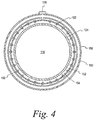
- Figure 4 depicts a cross-sectional view of the rocket 100 and the jacket 130 through a circumferential axis 4 shown in Figure 2 .
- the jacket 130 coupled to the rocket 100 forms an enclosed space 152 between the jacket 130 and the rocket 100.
- the enclosed space 152 is formed between an inner surface 154 of the jacket 130 and the exterior surface 124 of the rocket 100.
- the jacket 130 can include one or more spacers 156 extending from the inner surface 154 toward the exterior surface 124 of the rocket 100. Maintaining a gap between the inner surface 154 of the jacket 130 and the exterior surface 124 of the rocket 100 can beneficially help to disperse the cryogen over a greater surface area of the rocket 100.
- the jacket 130 further includes an outer surface 158.
- the inner surface 154 and/or the outer surface 158 of the jacket 130 can be made from an insulating material such as, for example polyurethane and/or Mylar. Forming the jacket 130 from an insulating material can improve controlling the temperature of the rocket 100 and enhance cooling efficiency. Additionally, the insulating material of the jacket 130 can help to keep most air out of the enclosed space 152 and thereby inhibit (or prevent) ice formation on the rocket 100.
- the inner surface 154 and the outer surface 158 define an interior chamber 160 in the jacket 130.
- the cryogen inlet 138 couples the cryogen-supply conduit 140 to the interior chamber 160.
- the cryogen inlet 138 thus facilitates receiving the cryogen from the cryogen source 132 into the interior chamber 160 of the jacket 130.
- the interior chamber 160 transfers the cryogen to one or more cryogen outlets 162 in the inner surface 154 of the jacket 130.
- the interior chamber 160 can include one or more jacket conduits 164 for directing the cryogen through the interior chamber 160 from the cryogen inlet 138 to the cryogen outlet(s) 162.
- the cryogen outlet(s) 162 transfer the cryogen from the interior chamber 160 in the jacket 130 to the rocket 100 in the enclosed space 152.
- the jacket 130 includes a plurality of cryogen outlets 162 along the longitudinal axis 3 of the jacket 130 for providing the cryogen along a length of the rocket 100, and along the circumferential axis 4 of the jacket 130 for providing the cryogen around a circumference of the rocket 100.
- the jacket 130 can disperse the cryogen over a greater surface area of the exterior surface 124 of the rocket 100 so as to better cool the rocket 100.
- each cryogen outlet 162 can include a nozzle that sprays the cryogen onto the exterior surface 124 of the rocket 100. Spray nozzles can further help to disperse the cryogen over increased surface area of the exterior surface.
- each cryogen outlet 162 can be an aperture in the inner surface 154 of the jacket 130.
- the rocket fueling system 126 can include a control system for controlling a flow rate of the cryogen transferred from the cryogen source 132 to the rocket 100 via the jacket 130.
- the control system can include a controller 166 communicatively coupled (e.g., via a wired and/or wireless connection) to the cryogen source 132, as shown in Figure 2 .
- the cryogen source 132 can include a valve 168 that can open and close to increase and decrease, respectively, the flow rate of cryogen.
- the controller 166 can be operable to transmit a control signal to the cryogen source 132 to cause the cryogen source 132 to open and close the valve 168 based on the control signal.
- the control system can further include one or more temperature sensors that are operable to measure a temperature of the rocket 100.
- the jacket 130 includes a temperature sensor 170 coupled to the inner surface 154 of the jacket 130 that can measure a temperature at the exterior surface 124 of the rocket 100.
- the temperature sensor 170 is communicatively coupled to the controller 166 (e.g., via wired and/or wireless connection) and operable to transmit to the controller 166 a temperature signal indicating the measured temperature. Based on the received temperature signal, the controller 166 can transmit a control signal to the cryogen source 132.
- the temperature sensor 170, the controller 166, and the cryogen source 132 can thus provide a closed-loop feedback control system for adjustably controlling the flow rate of cryogen provided to the rocket 100.
- the controller 166 can process the temperature signal by comparing the measured temperature to one or more threshold values and, based on the comparison, transmit the control signal to the cryogen source 132.
- the threshold value can be the liquefaction temperature of the rocket fuel. If the controller 166 determines that the measured temperature is above the threshold value, the controller 166 can cause the cryogen source 132 to increase the flow rate of cryogen. Whereas, if the controller 166 determines that the measured temperature is below the threshold value, the controller 166 can cause the cryogen source 132 to decrease the flow rate of cryogen.
- controller 166 can be implemented using hardware, software, and/or firmware.
- controller 166 can include one or more processors and a non-transitory computer readable medium (e.g., volatile and/or non-volatile memory) that stores machine language instructions or other executable instructions.
- the instructions when executed by the one or more processors, may cause controller 166 to carry out the various operations of the rocket fueling system 126 described herein.
- the cryogen may accumulate in the form of a gas within the enclosed space 152.
- a liquid cryogen may boil and become a cryogen gas in response to contact with the exterior surface 124 of the rocket 100.
- the jacket 130 can include a gas outlet 172 for exhausting the cryogen gas from the enclosed space 152 to an external environment. The gas outlet 172 can thus help to reduce or eliminate pressure build-up within the enclosed space 152.
- the jacket 130 can enclose the fuel inlet 122 in the enclosed space 152.
- the jacket 130 can be configured to provide access for the fuel-supply conduit 142 to the fuel inlet 122.
- the jacket 130 can have an aperture (not shown) through which the fuel-supply conduit 142 can pass to reach the fuel inlet 122. If the fuel-supply conduit 142 is not fully coupled to the fuel inlet 122 or if the fuel-supply conduit 142 has a leak, a portion of the gaseous rocket fuel may leak into the enclosed space 152 instead of transfer to the fuel chamber 116. Because the rocket fuel is a flammable gas, a rocket fuel leak can present significant safety issues if not mitigated promptly.
- the rocket fueling system 126 can detect and assist in mitigating a rocket fuel leak.
- the rocket fueling system 126 can include a gas sensor 174, which can detect the presence of a flammable gas such as the rocket fuel used to fuel the rocket 100.
- the gas sensor 174 is at the gas outlet 172; however the gas sensor 174 can be coupled to the other features of the jacket 130 in other examples. Responsive to the gas sensor 174 detecting the flammable gas exhausting through the gas outlet 172, the gas sensor 174 can provide an alarm signal to an alarm system 176 (shown in Figure 2 ).
- the alarm system 176 can include one or more output devices 178 that provide at least one of a visual alarm or an audio alarm responsive to the alarm signal.
- the output device(s) 178 can include one or more indicator lights, display devices, speakers, and/or sirens that can notify an operator that a flammable gas has been detected by the gas sensor 174. When notified of the detected flammable gas, the operator can then terminate the flow of the gas mixture from the fuel source system 128 to the fuel chamber 116 in the rocket 100.
- the gas sensor 174 can transmit the alarm signal to a controller 180 of the alarm system 176. Responsive to the alarm signal, the controller 180 can transmit a control signal to the fuel source system 128 to cause fuel source system 128 to terminate transferring the fuel chamber 116 in the rocket 100.
- the fuel source system 128 can include a valve 182 that can open and close responsive to the control signal from the controller 180 to increase and decrease, respectively, the flow of the gas mixture from the fuel source system 128 to the rocket 100.
- the alarm system 176 can be operable to automatically terminate the flow of the rocket fuel to assist in mitigating potentially unsafe conditions due to a rocket fuel leak.
- the jacket 130 can be coupled to at least a portion of the rocket 100, and the cryogen source 132 can be coupled to the jacket 130.
- the cryogen source 132 can be coupled to the jacket 130, for example, by coupling the cryogen-supply conduit 140 to the cryogen inlet 138 of the jacket 130.
- the cryogen source 132 can then transfer the cryogen to the internal chamber 116 of the jacket 130.
- the cryogen flows from the cryogen inlet 138 to the cryogen outlets 162.
- the cryogen outlets 162 transfer the cryogen from the internal chamber 116 of the jacket 130 to the exterior surface 124 of the rocket 100 in the enclosed space 152.
- the cryogen cools the rocket 100, for example, to a temperature at or below a liquefaction temperature of the gaseous rocket fuel to be supplied by the fuel source system 128. After contacting the exterior surface 124 of the rocket 100, the cryogen exhausts from the enclosed space 152 as a cryogen gas to an external environment via the gas outlet 172 in the jacket 130.
- the fuel source system 128 transfers the gas mixture to the fuel chamber 116 in the rocket 100.
- the jacket 130 and the cryogen source 132 can continue to cool the rocket 100 while the fuel source system 128 transfers the gas mixture to the fuel chamber 116.
- the gas mixture liquefies due to the rocket 100 being cooled to the temperature at or below the liquefaction temperature of the gas mixture.
- the rocket fueling systems and methods of the present disclosure can provide a number benefits relative to conventional systems and methods.
- the rocket fuel may be manufactured in large quantities and then stored as a liquid in temperature-controlled storage containers until needed to fuel a rocket.
- This may require specialized storage containers (e.g., including heat exchangers) and/or large temperature-controlled environments for storing containers of the liquid rocket fuel, both of which can be expensive.
- storing large quantities of highly combustible rocket fuel can also present safety issues.
- the systems and methods of the present disclosure allow for producing and liquefying rocket fuel in an on-demand manner and while fueling the rocket. Because the rocket fuel can be produced on-demand while fueling the rocket, the systems and methods of the present disclosure can more efficiently allow an operator to mix only as much rocket fuel as is needed to fuel the rocket. As such, the need to store large quantities of highly combustible rocket fuel prior to fueling the rocket may be mitigated. Instead, the gas components of the rocket fuel can be stored in separate containers prior to fueling the rocket. In its component parts, the rocket fuel can be stored in containers and environments having less stringent handling requirements than those required by conventional systems. For instance, the gas components can be stored at room temperature or at ambient outdoor temperature environments. Additionally, for instance, the gas components can be stored in DOT-approved gas storage containers.
- the systems and methods of the present disclosure can also provide for more rapid fueling of a rocket relative to conventional systems and methods.
- the rocket is cooled so that the rocket fuel remains a liquid when transferred to the rocket.
- the rocket is cooled only after the rocket is transported from a storage location to a launch location or site (e.g., after positioning the rocket on a launch pad). Accordingly, the time conventionally required to fuel a rocket depends in part on the amount of time it takes to cool the rocket after the rocket has been transported to and positioned at the launch location.
- the systems and methods of the present disclosure can beneficially reduce the time to fuel the rocket by initiating the cooling process before and/or while transporting the rocket from a storage location to the launch location.
- the rocket may already be cooled to a predetermined temperature (e.g., the temperature at or below the liquefaction temperature of the rocket fuel) by the time the rocket is positioned on a launch pad.
- a predetermined temperature e.g., the temperature at or below the liquefaction temperature of the rocket fuel
- Figure 5 depicts the rocket fueling system 126 cooling the rocket 100 while a vehicle 184 transports the rocket 100 from a storage location to a launch location.
- the rocket 100 can be cooled by the cryogen source 132 and the jacket 130 during transportation so as to prepare the rocket 100 for fueling at the launch location.
- the time required to fuel the rocket 100 can be reduced.
- the rocket 100 can be cooled to the temperature at or below the liquefaction temperature of the rocket fuel during transport so that the rocket 100 is ready to receive the rocket fuel in the fuel chamber 116 shortly (or immediately) after arriving at the launch location.
- the vehicle 184 can optionally transport the gas components of the rocket fuel in the gas component storage containers 148A, 148B.
- the gas component storage containers 148A, 148B can be DOT-approved storage containers so that the rocket fuel can be safely and cost-effectively transported on public roadways (e.g., from the storage location to the launch location).
- the rocket fueling systems and methods of the present disclosure can more safely fuel a rocket than conventional systems and methods.
- some conventional systems and methods cool the rocket on the launch site by spraying the rocket fuel itself on the exterior surface of the rocket.
- the rocket can be cooled using a cryogen that is a different substance than the substances used as rocket fuel.
- the rocket can be cooled by an inert cryogen substance that is not combustible within examples of the present disclosure. By using an inert cryogen substance to cool the rocket, the risk of first and/or explosion can be reduced.
- the process begins at block 192 by coupling an insulated jacket to an exterior surface of the rocket.
- the process includes cooling the exterior surface of the rocket by transferring, via the insulated jacket, a cryogen from a cryogen source to the exterior surface of the rocket.
- the exterior surface of the rocket can be cooled to a temperature at or below a liquefaction temperature of a gas mixture to be transferred to the rocket.
- the process includes transferring the gas mixture from an external fuel source to a fuel chamber in the rocket.
- a first gas component and a second gas component can be transferred to a mixing compartment of a gas-mixing system, the first gas component and the second gas component can be mixed in the mixing compartment to form the gas mixture, and the gas mixture can be transferred from the mixing compartment to the fuel chamber in the rocket.
- mixing the gas components and transferring the gas mixture can be performed simultaneously.
- the process includes liquefying the gas mixture in the fuel chamber to form a liquid rocket fuel in the fuel chamber.
- Figures 7-9 depicts additional aspects of the process 190 according to further examples.
- the process 190 further includes transporting rocket from a storage location to a launch location and cooling the exterior surface of the rocket while transporting the rocket.
- the process 190 can also include transporting at least two gas containers, each containing a different gas component of the gas mixture, from the storage location to the launch location while transporting the rocket from the storage location to the launch location at block 200.
- the process 190 can include detecting, via a gas sensor in the insulated jacket, a portion of the gas mixture at block 204.
- the process 190 includes terminating transferring the gas mixture to the fuel chamber in the rocket.
- a rocket fueling system comprising:
- the cryogen is configured to cool the rocket to a temperature that is less than a liquefaction temperature of a gaseous fuel for the rocket.
- the cryogen outlet comprises a plurality of cryogen outlets along a longitudinal axis of the insulated jacket for providing the cryogen along a length of the at least the portion of the rocket.
- the plurality of cryogen outlets are along a circumferential axis of the insulated jacket for providing the cryogen around a circumference of the at least the portion of the rocket.
- the insulated jacket includes a conduit for directing the cryogen from the cryogen inlet to the cryogen outlet.
- the rocket fueling system further comprises an alarm system coupled to the gas sensor, wherein the alarm system is configured to generate at least one of a visual alarm or an audio alarm in response to the gas sensor detecting the flammable gas at the gas outlet.
- the rocket fueling system further comprises a temperature sensor coupled to the insulated jacket, wherein the temperature sensor is configured to measure a temperature of an exterior surface of the at least the portion of the rocket.
- the rocket fueling system further comprises a controller communicatively coupled to the temperature sensor and a cryogen source, wherein the controller is configured to control, based on the temperature measured by the temperature sensor, a flow rate of the cryogen provided from the cryogen source to the at least the portion of the rocket.
- the cryogen is inert.
- an inner surface of the insulated jacket comprises a plurality of spacers configured to form a gap between the inner surface of the insulated jacket and an exterior surface of the at least the portion rocket.
- the rocket fueling system further comprises a gas-mixing system configured to mix a plurality of gas components to form a gas mixture; and a fuel-supply conduit for providing the gas mixture from the gas-mixing system to the rocket.
- the insulated jacket comprises a flexible material, and wherein the insulated jacket is configured to removably couple to the at least the portion of the rocket by wrapping around an exterior surface of the at least the portion of the rocket.
- a method of fueling a rocket comprising:
- cooling the exterior surface comprises cooling the exterior surface to a temperature below a liquefaction temperature of the gas mixture.
- cooling the exterior surface of the rocket comprises cooling the exterior surface of the rocket prior to and during transferring the gas mixture to the fuel chamber.
- transferring the gas mixture to the fuel chamber comprises:
- the method further comprises transporting the rocket from a storage location to a launch location, wherein cooling the exterior surface of the rocket is performed while transporting the rocket.
- the method further comprises transporting at least two gas containers, each containing a different gas component of the gas mixture, from the storage location to the launch location while transporting the rocket from the storage location to the launch location.
- the method further comprises:
Landscapes
- Engineering & Computer Science (AREA)
- Chemical & Material Sciences (AREA)
- Combustion & Propulsion (AREA)
- Mechanical Engineering (AREA)
- General Engineering & Computer Science (AREA)
- Remote Sensing (AREA)
- Aviation & Aerospace Engineering (AREA)
- Physics & Mathematics (AREA)
- Plasma & Fusion (AREA)
- Astronomy & Astrophysics (AREA)
- General Physics & Mathematics (AREA)
- Filling Or Discharging Of Gas Storage Vessels (AREA)
Abstract
Description
- The present disclosure generally relates to rocket fueling systems, and more particularly to, methods and systems that provide for fueling a rocket by liquefying a gaseous rocket fuel in a fuel chamber of the rocket.
- Unless otherwise indicated herein, the materials described in this section are not prior art to the claims and are not admitted to be prior art by inclusion in this section.
- Rockets are generally used to move payloads (e.g., satellites or astronauts) from the surface of the Earth to a desired orbit or trajectory. In some instances, a rocket can launch a payload to orbit in outer space. In other instances, the rocket can move the payload in a suborbital manner from one location to another. To deliver the payload to the intended destination, a rocket has a rocket engine that utilizes a rocket fuel to propel the rocket through the atmosphere and/or space. The rocket fuel is contained within the rocket throughout travel and, thus, the rocket must be fueled prior to launch. Fueling a rocket can be a potentially time consuming and costly process.
- For example, using existing techniques, it can take a relatively long time to fuel a rocket with a liquid rocket fuel because, after the rocket is moved to a launch site, the rocket must be cooled to a temperature suitable for receiving the liquid rocket fuel (i.e., below a boiling point of the rocket fuel). Additionally, for example, existing techniques for fueling a rocket with a liquid rocket fuel generally involve storing relatively large quantities of highly combustible rocket fuel in temperature controlled environments for extended periods of time.
- A method and system for fueling a rocket is disclosed. In an example, a rocket fueling system includes an insulated jacket configured to removably couple to at least a portion of a rocket and form an enclosed space between the insulated jacket and the at least the portion of the rocket. The rocket fueling system also includes a cryogen inlet in the insulated jacket. The cryogen inlet is configured to receive a cryogen into an interior chamber of the insulated jacket. The rocket fueling system further includes a cryogen outlet in the insulated jacket. The cryogen outlet is configured to provide the cryogen from the interior chamber in the insulated jacket to the at least the portion of the rocket in the enclosed space. The rocket fueling system still further includes a gas outlet in the insulated jacket configured to exhaust the cryogen from the enclosed space, and a gas sensor configured to detect a flammable gas at the gas outlet.
- In another example, a method of fueling a rocket includes coupling an insulated jacket to an exterior surface of the rocket, cooling the exterior surface of the rocket by transferring, via the insulated jacket, a cryogen from a cryogen source to the exterior surface of the rocket, transferring a gas mixture from an external fuel source to a fuel chamber in the rocket, and liquefying the gas mixture in the fuel chamber to form a liquid rocket fuel in the fuel chamber.
- These as well as other aspects, advantages, and alternatives will become apparent to those of ordinary skill in the art by reading the following detailed description with reference where appropriate to the accompanying drawings. Further, it should be understood that the description provided in this summary section and elsewhere in this document is intended to illustrate the claimed subject matter by way of example and not by way of limitation.
- The novel features believed characteristic of the illustrative embodiments are set forth in the appended claims. The illustrative embodiments, however, as well as a preferred mode of use, further objectives and descriptions thereof, will best be understood by reference to the following detailed description of an illustrative embodiment of the present disclosure when read in conjunction with the accompanying drawings.
-
Figure 1 depicts a perspective view of a rocket according to an example embodiment. -
Figure 2 depicts a perspective view of a rocket fueling system according to an example embodiment. -
Figure 3 depicts a cross-sectional view of the rocket and an insulated jacket of the rocket fueling system, according to an example embodiment. -
Figure 4 depicts another cross-sectional view of the rocket and the insulated jacket of the rocket fueling system, according to an example embodiment. -
Figure 5 depicts a side plan view of the rocket and the rocket fueling system during transport, according to an example embodiment. -
Figure 6 depicts a flow chart of an example process for fueling a rocket, according to an example embodiment. -
Figure 7 depicts a flow chart of another example process for fueling a rocket, according to an example embodiment. -
Figure 8 depicts a flow chart of another example process for fueling a rocket, according to an example embodiment. -
Figure 9 depicts a flow chart of another example process for fueling a rocket, according to an example embodiment. - The disclosed methods and systems provide for fueling a rocket.
Figure 1 depicts arocket 100 according to one example. As shown inFigure 1 , therocket 100 includes apayload portion 110 coupled to avehicle portion 112. Thepayload portion 110 can contain apayload 114 such as, for example, one or more satellites, space probes, space station components, cargo, astronauts, and/or animals, among other possibilities. In the illustrated example, thepayload portion 110 of therocket 100 is formed as a nose cone to facilitate aerodynamic performance of therocket 100; however, thepayload portion 110 can be formed with a different shape in other examples. - The
vehicle portion 112 provides a rocket engine for propelling therocket 100 during launch and/or flight. For example, thevehicle portion 112 can include one or moreinternal fuel chambers 116 for containing a rocket fuel (i.e., a propellant),combustion chambers 118, and/orrocket engine nozzles 120. Thevehicle portion 112 can also include afuel inlet 122 in anexterior surface 124 of therocket 100 to facilitate transferring the rocket fuel from an external fuel source to theinternal fuel chamber 116. Thefuel chamber 116 is coupled to thecombustion chamber 118 so that the rocket fuel can be transferred from theinternal fuel chamber 116 to thecombustion chamber 118. Thecombustion chamber 118 can combust the rocket fuel to produce a hot, high pressure gas. Thecombustion chamber 118 is coupled to therocket engine nozzle 120, which exhausts the hot, high pressure gas away from the vehicle. Therocket engine nozzle 120 can facilitate accelerating the gas received from thecombustion chamber 118 to facilitate converting thermal energy of the gas into kinetic energy of therocket 100. - In addition to the features shown in
Figure 1 , therocket 100 can include additional or alternative features such as, for example, one or more navigation and/or guidance systems (e.g., a satellite navigation system and/or an inertial navigation system), and/or stabilization devices (e.g., one or more fins, Vernier engines, gimbals, and/or gyroscopes). -
Figure 2 depicts arocket fueling system 126 according to an example of the present disclosure. Therocket fueling system 126 includes afuel source system 128, aninsulated jacket 130, and acryogen source 132. As described in detail below, thejacket 130 couples to therocket 100, thecryogen source 132 transfers a cryogen to thejacket 130, and thejacket 130 then disperses the cryogen over at least a portion of therocket 100. The cryogen cools therocket 100 to a temperature at or below a liquefaction temperature of a rocket fuel to be provided by thefuel source system 128. For example, the cryogen can cool the rocket to a temperature between approximately -20 degrees Fahrenheit to approximately -100 degrees Fahrenheit. By cooling therocket 100 with the cryogen, thefuel source system 128 can transfer the rocket fuel to thefuel chamber 116 as a gas, which then liquefies in thefuel chamber 116 of therocket 100. The liquefied fuel is usable by therocket 100 as a propellant for launch and/or flight. - As shown in
Figure 2 , theinsulated jacket 130 is removably coupled to at least a portion of therocket 100. In an example, thejacket 130 is made from a flexible material such as, for instance, Teflon and/or Mylar (among other possibilities). In this example, thejacket 130 can be removably coupled to therocket 100 by wrapping thejacket 130 around theexterior surface 124 of therocket 100 and then removably coupling opposing ends 134A, 134B of thejacket 130 to each other. For instance, the opposing ends 134A, 134B can be removably coupled to each other by afastener 136 such as, for example, snap-fit retention features, hook-and-loop fasteners (e.g., VELCRO®), zippers, buttons, and/or straps and buckles. - In
Figure 2 , thejacket 130 is coupled to thevehicle portion 112 of therocket 100. This may beneficially allow thejacket 130 to cool the portion of therocket 100 in which the rocket fuel is or will be contained; however, thejacket 130 can be coupled to a different portion of therocket 100 and/or to theentire rocket 100 in other examples. - The
jacket 130 includes acryogen inlet 138 for coupling thejacket 130 to the cryogen source 132 (e.g., via a cryogen-supply conduit 140). The cryogen can include, for example, liquid nitrogen, liquid helium, liquid argon, liquid neon, and/or liquid krypton. In some examples, the cryogen can be an inert substance. This can be beneficial in that the inert cryogen is not combustible, which helps to facilitate safe fueling therocket 100. - The
fuel source system 128 is coupled to thefuel inlet 122 ofrocket 100 by a fuel-supply conduit 142 to facilitate transferring a gaseous rocket fuel from thefuel source system 128 to thefuel chamber 116 in therocket 100. Thefuel source system 128 includes a plurality ofgas storage containers system 146. Thegas storage containers first container 144A can store an oxidizer gas component (e.g., nitrous oxide) and asecond container 144B can store a hydrocarbon gas component (e.g., propane, ethane, or ethetalyne). Thegas storage containers - The
gas storage containers system 146, for example, byrespective gas conduits gas storage containers system 146, and the gas-mixingsystem 146 can then mix the gas components in amixing compartment 150 to form a gas mixture of rocket fuel. The gas-mixingsystem 146 is coupled to thefuel inlet 122 of therocket 100 via the fuel-supply conduit 142 to facilitate transferring the gas mixture to thefuel chamber 116. In thefuel chamber 116, the gas-mixture cools and liquefies to form a liquid rocket fuel as a propellant for operation of therocket 100. - In line with the discussion above, the
jacket 130 receives the cryogen from thecryogen source 132, and thejacket 130 then provides the cryogen to therocket 100 to cool the rocket to a temperature at or below the liquefaction temperature of the gas mixture.Figures 3-4 depict cross-sectional views of therocket 100 andjacket 130 to further illustrate aspects of thejacket 130. In particular,Figure 3 depicts a cross-sectional view of therocket 100 andjacket 130 through alongitudinal axis 3 shown inFigure 2 , andFigure 4 depicts a cross-sectional view of therocket 100 and thejacket 130 through acircumferential axis 4 shown inFigure 2 . - As shown in
Figures 3-4 , thejacket 130 coupled to therocket 100 forms anenclosed space 152 between thejacket 130 and therocket 100. In particular, theenclosed space 152 is formed between aninner surface 154 of thejacket 130 and theexterior surface 124 of therocket 100. To help maintain a gap between theinner surface 154 of thejacket 130 and theexterior surface 124 of therocket 100, thejacket 130 can include one ormore spacers 156 extending from theinner surface 154 toward theexterior surface 124 of therocket 100. Maintaining a gap between theinner surface 154 of thejacket 130 and theexterior surface 124 of therocket 100 can beneficially help to disperse the cryogen over a greater surface area of therocket 100. - The
jacket 130 further includes anouter surface 158. Theinner surface 154 and/or theouter surface 158 of thejacket 130 can be made from an insulating material such as, for example polyurethane and/or Mylar. Forming thejacket 130 from an insulating material can improve controlling the temperature of therocket 100 and enhance cooling efficiency. Additionally, the insulating material of thejacket 130 can help to keep most air out of theenclosed space 152 and thereby inhibit (or prevent) ice formation on therocket 100. - As further shown in
Figures 3-4 , theinner surface 154 and theouter surface 158 define aninterior chamber 160 in thejacket 130. Thecryogen inlet 138 couples the cryogen-supply conduit 140 to theinterior chamber 160. Thecryogen inlet 138 thus facilitates receiving the cryogen from thecryogen source 132 into theinterior chamber 160 of thejacket 130. Theinterior chamber 160 transfers the cryogen to one ormore cryogen outlets 162 in theinner surface 154 of thejacket 130. To improve cryogen flow in thejacket 130, theinterior chamber 160 can include one ormore jacket conduits 164 for directing the cryogen through theinterior chamber 160 from thecryogen inlet 138 to the cryogen outlet(s) 162. - The cryogen outlet(s) 162 transfer the cryogen from the
interior chamber 160 in thejacket 130 to therocket 100 in theenclosed space 152. As shown inFigures 3-4 , thejacket 130 includes a plurality ofcryogen outlets 162 along thelongitudinal axis 3 of thejacket 130 for providing the cryogen along a length of therocket 100, and along thecircumferential axis 4 of thejacket 130 for providing the cryogen around a circumference of therocket 100. By providing a plurality ofcryogen outlets 162, thejacket 130 can disperse the cryogen over a greater surface area of theexterior surface 124 of therocket 100 so as to better cool therocket 100. In one example, eachcryogen outlet 162 can include a nozzle that sprays the cryogen onto theexterior surface 124 of therocket 100. Spray nozzles can further help to disperse the cryogen over increased surface area of the exterior surface. As another example, eachcryogen outlet 162 can be an aperture in theinner surface 154 of thejacket 130. - The
rocket fueling system 126 can include a control system for controlling a flow rate of the cryogen transferred from thecryogen source 132 to therocket 100 via thejacket 130. In one example, the control system can include acontroller 166 communicatively coupled (e.g., via a wired and/or wireless connection) to thecryogen source 132, as shown inFigure 2 . Thecryogen source 132 can include avalve 168 that can open and close to increase and decrease, respectively, the flow rate of cryogen. Thecontroller 166 can be operable to transmit a control signal to thecryogen source 132 to cause thecryogen source 132 to open and close thevalve 168 based on the control signal. - The control system can further include one or more temperature sensors that are operable to measure a temperature of the
rocket 100. For instance, inFigure 3 , thejacket 130 includes atemperature sensor 170 coupled to theinner surface 154 of thejacket 130 that can measure a temperature at theexterior surface 124 of therocket 100. Thetemperature sensor 170 is communicatively coupled to the controller 166 (e.g., via wired and/or wireless connection) and operable to transmit to the controller 166 a temperature signal indicating the measured temperature. Based on the received temperature signal, thecontroller 166 can transmit a control signal to thecryogen source 132. Thetemperature sensor 170, thecontroller 166, and thecryogen source 132 can thus provide a closed-loop feedback control system for adjustably controlling the flow rate of cryogen provided to therocket 100. - In one example, the
controller 166 can process the temperature signal by comparing the measured temperature to one or more threshold values and, based on the comparison, transmit the control signal to thecryogen source 132. For instance, the threshold value can be the liquefaction temperature of the rocket fuel. If thecontroller 166 determines that the measured temperature is above the threshold value, thecontroller 166 can cause thecryogen source 132 to increase the flow rate of cryogen. Whereas, if thecontroller 166 determines that the measured temperature is below the threshold value, thecontroller 166 can cause thecryogen source 132 to decrease the flow rate of cryogen. - The
controller 166 can be implemented using hardware, software, and/or firmware. For example,controller 166 can include one or more processors and a non-transitory computer readable medium (e.g., volatile and/or non-volatile memory) that stores machine language instructions or other executable instructions. The instructions, when executed by the one or more processors, may causecontroller 166 to carry out the various operations of therocket fueling system 126 described herein. - After the cryogen is transferred from the
jacket 130 to therocket 100, the cryogen may accumulate in the form of a gas within theenclosed space 152. For example, a liquid cryogen may boil and become a cryogen gas in response to contact with theexterior surface 124 of therocket 100. Thejacket 130 can include agas outlet 172 for exhausting the cryogen gas from theenclosed space 152 to an external environment. Thegas outlet 172 can thus help to reduce or eliminate pressure build-up within theenclosed space 152. - As shown in
Figures 2-3 , thejacket 130 can enclose thefuel inlet 122 in theenclosed space 152. To do so, thejacket 130 can be configured to provide access for the fuel-supply conduit 142 to thefuel inlet 122. For example, thejacket 130 can have an aperture (not shown) through which the fuel-supply conduit 142 can pass to reach thefuel inlet 122. If the fuel-supply conduit 142 is not fully coupled to thefuel inlet 122 or if the fuel-supply conduit 142 has a leak, a portion of the gaseous rocket fuel may leak into theenclosed space 152 instead of transfer to thefuel chamber 116. Because the rocket fuel is a flammable gas, a rocket fuel leak can present significant safety issues if not mitigated promptly. - In an example, the
rocket fueling system 126 can detect and assist in mitigating a rocket fuel leak. For instance, therocket fueling system 126 can include agas sensor 174, which can detect the presence of a flammable gas such as the rocket fuel used to fuel therocket 100. InFigures 2-3 , thegas sensor 174 is at thegas outlet 172; however thegas sensor 174 can be coupled to the other features of thejacket 130 in other examples. Responsive to thegas sensor 174 detecting the flammable gas exhausting through thegas outlet 172, thegas sensor 174 can provide an alarm signal to an alarm system 176 (shown inFigure 2 ). Thealarm system 176 can include one ormore output devices 178 that provide at least one of a visual alarm or an audio alarm responsive to the alarm signal. For example, the output device(s) 178 can include one or more indicator lights, display devices, speakers, and/or sirens that can notify an operator that a flammable gas has been detected by thegas sensor 174. When notified of the detected flammable gas, the operator can then terminate the flow of the gas mixture from thefuel source system 128 to thefuel chamber 116 in therocket 100. - In another example, the
gas sensor 174 can transmit the alarm signal to acontroller 180 of thealarm system 176. Responsive to the alarm signal, thecontroller 180 can transmit a control signal to thefuel source system 128 to causefuel source system 128 to terminate transferring thefuel chamber 116 in therocket 100. For example, thefuel source system 128 can include avalve 182 that can open and close responsive to the control signal from thecontroller 180 to increase and decrease, respectively, the flow of the gas mixture from thefuel source system 128 to therocket 100. As such, thealarm system 176 can be operable to automatically terminate the flow of the rocket fuel to assist in mitigating potentially unsafe conditions due to a rocket fuel leak. - In operation, the
jacket 130 can be coupled to at least a portion of therocket 100, and thecryogen source 132 can be coupled to thejacket 130. Thecryogen source 132 can be coupled to thejacket 130, for example, by coupling the cryogen-supply conduit 140 to thecryogen inlet 138 of thejacket 130. Thecryogen source 132 can then transfer the cryogen to theinternal chamber 116 of thejacket 130. In theinterior chamber 160 of thejacket 130, the cryogen flows from thecryogen inlet 138 to thecryogen outlets 162. Thecryogen outlets 162 transfer the cryogen from theinternal chamber 116 of thejacket 130 to theexterior surface 124 of therocket 100 in theenclosed space 152. The cryogen cools therocket 100, for example, to a temperature at or below a liquefaction temperature of the gaseous rocket fuel to be supplied by thefuel source system 128. After contacting theexterior surface 124 of therocket 100, the cryogen exhausts from theenclosed space 152 as a cryogen gas to an external environment via thegas outlet 172 in thejacket 130. - After the
rocket 100 is cooled by the cryogen to a predetermined temperature (e.g., the temperature at or below the liquefaction temperature of the gas mixture), thefuel source system 128 transfers the gas mixture to thefuel chamber 116 in therocket 100. In an example, thejacket 130 and thecryogen source 132 can continue to cool therocket 100 while thefuel source system 128 transfers the gas mixture to thefuel chamber 116. In thefuel chamber 116, the gas mixture liquefies due to therocket 100 being cooled to the temperature at or below the liquefaction temperature of the gas mixture. - The rocket fueling systems and methods of the present disclosure can provide a number benefits relative to conventional systems and methods. For example, in a conventional system, the rocket fuel may be manufactured in large quantities and then stored as a liquid in temperature-controlled storage containers until needed to fuel a rocket. This may require specialized storage containers (e.g., including heat exchangers) and/or large temperature-controlled environments for storing containers of the liquid rocket fuel, both of which can be expensive. Additionally, storing large quantities of highly combustible rocket fuel can also present safety issues.
- By contrast, the systems and methods of the present disclosure allow for producing and liquefying rocket fuel in an on-demand manner and while fueling the rocket. Because the rocket fuel can be produced on-demand while fueling the rocket, the systems and methods of the present disclosure can more efficiently allow an operator to mix only as much rocket fuel as is needed to fuel the rocket. As such, the need to store large quantities of highly combustible rocket fuel prior to fueling the rocket may be mitigated. Instead, the gas components of the rocket fuel can be stored in separate containers prior to fueling the rocket. In its component parts, the rocket fuel can be stored in containers and environments having less stringent handling requirements than those required by conventional systems. For instance, the gas components can be stored at room temperature or at ambient outdoor temperature environments. Additionally, for instance, the gas components can be stored in DOT-approved gas storage containers.
- Beneficially, the systems and methods of the present disclosure can also provide for more rapid fueling of a rocket relative to conventional systems and methods. To fuel the rocket, the rocket is cooled so that the rocket fuel remains a liquid when transferred to the rocket. Conventionally, the rocket is cooled only after the rocket is transported from a storage location to a launch location or site (e.g., after positioning the rocket on a launch pad). Accordingly, the time conventionally required to fuel a rocket depends in part on the amount of time it takes to cool the rocket after the rocket has been transported to and positioned at the launch location.
- The systems and methods of the present disclosure can beneficially reduce the time to fuel the rocket by initiating the cooling process before and/or while transporting the rocket from a storage location to the launch location. In some instances, the rocket may already be cooled to a predetermined temperature (e.g., the temperature at or below the liquefaction temperature of the rocket fuel) by the time the rocket is positioned on a launch pad. In this way, the systems and methods of the present disclosure can ready the rocket to receive the rocket fuel significantly faster than in conventional systems and methods.
- As an example,
Figure 5 depicts therocket fueling system 126 cooling therocket 100 while avehicle 184 transports therocket 100 from a storage location to a launch location. As shown inFigure 5 , therocket 100 can be cooled by thecryogen source 132 and thejacket 130 during transportation so as to prepare therocket 100 for fueling at the launch location. By cooling therocket 100 during transportation, the time required to fuel therocket 100 can be reduced. For example, therocket 100 can be cooled to the temperature at or below the liquefaction temperature of the rocket fuel during transport so that therocket 100 is ready to receive the rocket fuel in thefuel chamber 116 shortly (or immediately) after arriving at the launch location. - As also shown in
Figure 5 , thevehicle 184 can optionally transport the gas components of the rocket fuel in the gascomponent storage containers component storage containers - Still further, the rocket fueling systems and methods of the present disclosure can more safely fuel a rocket than conventional systems and methods. For example, some conventional systems and methods cool the rocket on the launch site by spraying the rocket fuel itself on the exterior surface of the rocket. By contrast, in examples, the rocket can be cooled using a cryogen that is a different substance than the substances used as rocket fuel. For example, the rocket can be cooled by an inert cryogen substance that is not combustible within examples of the present disclosure. By using an inert cryogen substance to cool the rocket, the risk of first and/or explosion can be reduced.
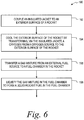
- Referring now to
Figure 6 , a flowchart is depicted for aprocess 190 of fueling a rocket according to one example. As shown inFigure 6 , the process begins at block 192 by coupling an insulated jacket to an exterior surface of the rocket. At block 194, the process includes cooling the exterior surface of the rocket by transferring, via the insulated jacket, a cryogen from a cryogen source to the exterior surface of the rocket. For example, the exterior surface of the rocket can be cooled to a temperature at or below a liquefaction temperature of a gas mixture to be transferred to the rocket. Atblock 196, the process includes transferring the gas mixture from an external fuel source to a fuel chamber in the rocket. For instance, a first gas component and a second gas component can be transferred to a mixing compartment of a gas-mixing system, the first gas component and the second gas component can be mixed in the mixing compartment to form the gas mixture, and the gas mixture can be transferred from the mixing compartment to the fuel chamber in the rocket. In one implementation, mixing the gas components and transferring the gas mixture can be performed simultaneously. Atblock 198, the process includes liquefying the gas mixture in the fuel chamber to form a liquid rocket fuel in the fuel chamber. -
Figures 7-9 depicts additional aspects of theprocess 190 according to further examples. As shown inFigure 7 , atblock 200, theprocess 190 further includes transporting rocket from a storage location to a launch location and cooling the exterior surface of the rocket while transporting the rocket. As shown inFigure 8 , atblock 202, theprocess 190 can also include transporting at least two gas containers, each containing a different gas component of the gas mixture, from the storage location to the launch location while transporting the rocket from the storage location to the launch location atblock 200. As shown inFigure 9 , theprocess 190 can include detecting, via a gas sensor in the insulated jacket, a portion of the gas mixture atblock 204. Atblock 206, responsive to detecting the portion of the gas mixture, theprocess 190 includes terminating transferring the gas mixture to the fuel chamber in the rocket. - According to another arrangement, there is disclosed a rocket fueling system comprising:
- an insulated jacket configured to removably couple to at least a portion of a rocket and form an enclosed space between the insulated jacket and the at least the portion of the rocket;
- a cryogen inlet in the insulated jacket, wherein the cryogen inlet is configured to receive a cryogen into an interior chamber of the insulated jacket;
- a cryogen outlet in the insulated jacket, wherein the cryogen outlet is configured to provide the cryogen from the interior chamber in the insulated jacket to the at least the portion of the rocket in the enclosed space;
- a gas outlet in the insulated jacket configured to exhaust the cryogen from the enclosed space; and
- a gas sensor configured to detect a flammable gas at the gas outlet.
- Optionally, the cryogen is configured to cool the rocket to a temperature that is less than a liquefaction temperature of a gaseous fuel for the rocket.
- Optionally, the cryogen outlet comprises a plurality of cryogen outlets along a longitudinal axis of the insulated jacket for providing the cryogen along a length of the at least the portion of the rocket.
- Optionally, the plurality of cryogen outlets are along a circumferential axis of the insulated jacket for providing the cryogen around a circumference of the at least the portion of the rocket.
- Optionally, the insulated jacket includes a conduit for directing the cryogen from the cryogen inlet to the cryogen outlet.
- Optionally, the rocket fueling system further comprises an alarm system coupled to the gas sensor, wherein the alarm system is configured to generate at least one of a visual alarm or an audio alarm in response to the gas sensor detecting the flammable gas at the gas outlet.
- Optionally, the rocket fueling system further comprises a temperature sensor coupled to the insulated jacket, wherein the temperature sensor is configured to measure a temperature of an exterior surface of the at least the portion of the rocket.
- Optionally, the rocket fueling system further comprises a controller communicatively coupled to the temperature sensor and a cryogen source, wherein the controller is configured to control, based on the temperature measured by the temperature sensor, a flow rate of the cryogen provided from the cryogen source to the at least the portion of the rocket.
- Optionally, the cryogen is inert.
- Optionally, an inner surface of the insulated jacket comprises a plurality of spacers configured to form a gap between the inner surface of the insulated jacket and an exterior surface of the at least the portion rocket.
- Optionally, the rocket fueling system further comprises a gas-mixing system configured to mix a plurality of gas components to form a gas mixture; and
a fuel-supply conduit for providing the gas mixture from the gas-mixing system to the rocket. - Optionally the insulated jacket comprises a flexible material, and wherein the insulated jacket is configured to removably couple to the at least the portion of the rocket by wrapping around an exterior surface of the at least the portion of the rocket.
- According to another arrangement, there is disclosed a method of fueling a rocket, comprising:
- coupling an insulated jacket to an exterior surface of the rocket;
- cooling the exterior surface of the rocket by transferring, via the insulated jacket, a cryogen from a cryogen source to the exterior surface of the rocket;
- transferring a gas mixture from an external fuel source to a fuel chamber in the rocket; and
- liquefying the gas mixture in the fuel chamber to form a liquid rocket fuel in the fuel chamber.
- Optionally, cooling the exterior surface comprises cooling the exterior surface to a temperature below a liquefaction temperature of the gas mixture.
- Optionally, cooling the exterior surface of the rocket comprises cooling the exterior surface of the rocket prior to and during transferring the gas mixture to the fuel chamber.
- Optionally, transferring the gas mixture to the fuel chamber comprises:
- transferring a first gas component from a first gas source to a mixing compartment of a gas-mixing system;
- transferring a second gas component from a second gas source to the mixing compartment;
- mixing the first gas component and the second gas component in the mixing compartment to form the gas mixture; and
- transferring the gas mixture from the mixing compartment to the fuel chamber in the rocket.
- Optionally, (i) mixing the first gas component and the second gas component and (ii) transferring the gas mixture are performed simultaneously.
- Optionally, the method further comprises transporting the rocket from a storage location to a launch location, wherein cooling the exterior surface of the rocket is performed while transporting the rocket.
- Optionally, the method further comprises transporting at least two gas containers, each containing a different gas component of the gas mixture, from the storage location to the launch location while transporting the rocket from the storage location to the launch location.
- Optionally, the method further comprises:
- detecting, via a gas sensor in the insulated jacket, a portion of the gas mixture; and
- responsive to detecting the portion of the gas mixture, terminating transferring the gas mixture to the fuel chamber in the rocket.
- Example aspects have been described above. After studying the configurations, examples, and arrangements described herein a skilled person may come to understand, however, that changes and modifications may be made without departing from the true scope and spirit of the disclosure. The description of the different advantageous aspects has been presented for purposes of illustration and description, and is not intended to be exhaustive or limited to the form disclosed. After reviewing this disclosure, many modifications and variations will become apparent to those of ordinary skill in the art. Further, different advantageous aspects may provide different advantages as compared to other advantageous aspects. The example aspects selected are chosen and described in order to explain the principles of the disclosure, the practical application, and to enable others of ordinary skill in the art to understand the disclosure with various modifications as are suited to the particular use contemplated.
Claims (15)
- A rocket fueling system (126) comprising:an insulated jacket (130) configured to removably couple to at least a portion of a rocket (100) and form an enclosed space (152) between the insulated jacket (130) and the at least the portion of the rocket (100);a cryogen inlet (138) in the insulated jacket (130), wherein the cryogen inlet (138) is configured to receive a cryogen into an interior chamber (160) of the insulated jacket (130);a cryogen outlet (162) in the insulated jacket (130), wherein the cryogen outlet (162) is configured to provide the cryogen from the interior chamber (160) in the insulated jacket (130) to the at least the portion of the rocket (100) in the enclosed space (152);a gas outlet (172) in the insulated jacket (130) configured to exhaust the cryogen from the enclosed space (152); anda gas sensor (174) configured to detect a flammable gas at the gas outlet (172).
- The rocket fueling system (126) of claim 1, wherein the cryogen is configured to cool the rocket (100) to a temperature that is less than a liquefaction temperature of a gaseous fuel for the rocket (100).
- The rocket fueling system (126) of claim 1 or claim 2, wherein the cryogen outlet (162) comprises a plurality of cryogen outlets (162) along a longitudinal axis of the insulated jacket (130) for providing the cryogen along a length of the at least the portion of the rocket (100).
- The rocket fueling system (126) of claim 3, wherein the plurality of cryogen outlets (162) are along a circumferential axis (4) of the insulated jacket (130) for providing the cryogen around a circumference of the at least the portion of the rocket (100).
- The rocket fueling system (126) of any one of claims 1-4, wherein the insulated jacket (130) includes a conduit for directing the cryogen from the cryogen inlet (138) to the cryogen outlet (162).
- The rocket fueling system (126) of any one of claims 1-5, further comprising a temperature sensor (170) coupled to the insulated jacket (130), wherein the temperature sensor (170) is configured to measure a temperature of an exterior surface (124) of the at least the portion of the rocket (100).
- The rocket fueling system (126) of claim 6, further comprising a controller (166) communicatively coupled to the temperature sensor (170) and a cryogen source (132), wherein the controller (166) is configured to control, based on the temperature measured by the temperature sensor (170), a flow rate of the cryogen provided from the cryogen source (132) to the at least the portion of the rocket (100)..
- The rocket fueling system (126) of any one of claims 1-7, wherein an inner surface (154) of the insulated jacket (130) comprises a plurality of spacers (156) configured to form a gap between the inner surface (154) of the insulated jacket (130) and an exterior surface (124) of the at least the portion rocket (100).
- The rocket fueling system (126) of any one of claims 1-8, further comprising:a gas-mixing system (146) configured to mix a plurality of gas components to form a gas mixture; anda fuel-supply conduit (142) for providing the gas mixture from the gas-mixing system (146) to the rocket (100).
- The rocket fueling system (126) of any one of claims 1-9, wherein the insulated jacket (130) comprises a flexible material, and wherein the insulated jacket (130) is configured to removably couple to the at least the portion of the rocket (100) by wrapping around an exterior surface (124) of the at least the portion of the rocket (100).
- A method of fueling a rocket (100), comprising:coupling an insulated jacket (130) to an exterior surface (124) of the rocket (100);cooling the exterior surface of the rocket (100) by transferring, via the insulated jacket (130), a cryogen from a cryogen source (132) to the exterior surface (124) of the rocket (100);transferring a gas mixture from an external fuel source to a fuel chamber (116) in the rocket (100); andliquefying the gas mixture in the fuel chamber (116) to form a liquid rocket fuel in the fuel chamber (116).
- The method of claim 11, wherein cooling the exterior surface (124) comprises cooling the exterior surface (124) to a temperature below a liquefaction temperature of the gas mixture.
- The method of claim 11 or claim 12, wherein transferring the gas mixture to the fuel chamber (116) comprises:transferring a first gas component from a first gas source to a mixing compartment of a gas-mixing system;transferring a second gas component from a second gas source to the mixing compartment;mixing the first gas component and the second gas component in the mixing compartment to form the gas mixture; andtransferring the gas mixture from the mixing compartment to the fuel chamber (116) in the rocket (100).
- The method of any one of claims 11-13, further comprising transporting the rocket (100) from a storage location to a launch location, wherein cooling the exterior surface (124) of the rocket (100) is performed while transporting the rocket (100).
- The method of any one of claims 11-14, further comprising:detecting, via a gas sensor (174) in the insulated jacket (130), a portion of the gas mixture; andresponsive to detecting the portion of the gas mixture, terminating transferring the gas mixture to the fuel chamber (116) in the rocket (100).
Applications Claiming Priority (1)
| Application Number | Priority Date | Filing Date | Title |
|---|---|---|---|
| US15/216,129 US10934030B2 (en) | 2016-07-21 | 2016-07-21 | Rocket propellant mixing and fueling systems and methods |
Publications (2)
| Publication Number | Publication Date |
|---|---|
| EP3273046A1 true EP3273046A1 (en) | 2018-01-24 |
| EP3273046B1 EP3273046B1 (en) | 2020-10-28 |
Family
ID=59366336
Family Applications (1)
| Application Number | Title | Priority Date | Filing Date |
|---|---|---|---|
| EP17181944.4A Not-in-force EP3273046B1 (en) | 2016-07-21 | 2017-07-18 | Rocket fueling system and method of fueling a rocket |
Country Status (4)
| Country | Link |
|---|---|
| US (1) | US10934030B2 (en) |
| EP (1) | EP3273046B1 (en) |
| JP (1) | JP6936640B2 (en) |
| KR (1) | KR102354940B1 (en) |
Citations (2)
| Publication number | Priority date | Publication date | Assignee | Title |
|---|---|---|---|---|
| US2959023A (en) * | 1957-07-09 | 1960-11-08 | British Oxygen Co Ltd | Storage of liquefied gases |
| US3122891A (en) * | 1958-12-11 | 1964-03-03 | Air Prod & Chem | Cryogenic methods and apparatus |
Family Cites Families (7)
| Publication number | Priority date | Publication date | Assignee | Title |
|---|---|---|---|---|
| US5404923A (en) * | 1993-05-26 | 1995-04-11 | Rockwell International Corporation | Apparatus for automated fueling of a launch vehicle |
| US8009060B2 (en) * | 2001-09-26 | 2011-08-30 | Lockheed Martin Corporation | Remote monitoring of munition assets |
| EP2511611A1 (en) * | 2003-03-07 | 2012-10-17 | Shikoku Research Institute Incorporated | Hydrogen flame monitoring method and system |
| JP3783019B2 (en) * | 2003-03-07 | 2006-06-07 | 株式会社四国総合研究所 | Gas leakage monitoring method and system |
| EP2209876A4 (en) * | 2007-11-09 | 2014-01-08 | Firestar Engineering Llc | Nitrous oxide fuel blend monopropellants |
| US8776494B2 (en) * | 2010-06-22 | 2014-07-15 | Cal Poly Corporation | System, method and apparatus for cooling rocket motor components using a saturated liquid vapor coolant mixture |
| DE102015002708B3 (en) * | 2014-09-09 | 2015-10-22 | Mt Aerospace Ag | Containers for receiving and storing liquids and viscous substances, in particular cryogenic fluids, and process for its preparation and its use |
-
2016
- 2016-07-21 US US15/216,129 patent/US10934030B2/en not_active Expired - Fee Related
-
2017
- 2017-05-23 KR KR1020170063382A patent/KR102354940B1/en not_active Expired - Fee Related
- 2017-07-05 JP JP2017132112A patent/JP6936640B2/en not_active Expired - Fee Related
- 2017-07-18 EP EP17181944.4A patent/EP3273046B1/en not_active Not-in-force
Patent Citations (2)
| Publication number | Priority date | Publication date | Assignee | Title |
|---|---|---|---|---|
| US2959023A (en) * | 1957-07-09 | 1960-11-08 | British Oxygen Co Ltd | Storage of liquefied gases |
| US3122891A (en) * | 1958-12-11 | 1964-03-03 | Air Prod & Chem | Cryogenic methods and apparatus |
Also Published As
| Publication number | Publication date |
|---|---|
| KR20180010968A (en) | 2018-01-31 |
| US10934030B2 (en) | 2021-03-02 |
| US20180023512A1 (en) | 2018-01-25 |
| JP6936640B2 (en) | 2021-09-22 |
| EP3273046B1 (en) | 2020-10-28 |
| JP2018034781A (en) | 2018-03-08 |
| KR102354940B1 (en) | 2022-01-21 |
Similar Documents
| Publication | Publication Date | Title |
|---|---|---|
| US8281566B2 (en) | Thermally-integrated fluid storage and pressurization system | |
| US8596038B2 (en) | Liquid propellant tank and vapor jet emitting device including same | |
| US6374618B1 (en) | Cryogenic fluid supply from supercritical storage system | |
| US9909574B1 (en) | Electrothermal space thruster heater for decomposable propellants | |
| Swider-Lyons et al. | Liquid hydrogen fuel system for small unmanned air vehicles | |
| US11993401B2 (en) | Cold gas thruster with solid propellant | |
| EP1043227A2 (en) | An expendable launch vehicle | |
| JP4727019B2 (en) | Cryogenic fluid cooling method and cryogenic fluid cooling system | |
| Garceau et al. | Performance test of a 6 L liquid hydrogen fuel tank for unmanned aerial vehicles | |
| EP3273046B1 (en) | Rocket fueling system and method of fueling a rocket | |
| Taguchi et al. | Mach 4 wind tunnel experiment of hypersonic pre-cooled turbojet engine | |
| RU2270792C1 (en) | Launch complex for preparation and launching of launch vehicles with spacecraft | |
| Delee et al. | Techniques for on-orbit cryogenic servicing | |
| Tokudome et al. | An Experimental Study of an N2O/Ethanol Propulsion System with 2 kN Thrust Class BBM | |
| US20240125288A1 (en) | Rocket propulsion system | |
| Praveen et al. | Development of cryogenic engine for GSLV MkIII: technological challenges | |
| Doran et al. | Status update report for the Peregrine sounding rocket project: Part III | |
| Marquardt et al. | An overview of Ball Aerospace cryogen storage and delivery systems | |
| US20030089434A1 (en) | Method and apparatus for the preparation and usage of a cryogenic propellant or explosive system | |
| Krenn et al. | Flight servicing of robotic refueling mission 3 | |
| CN104937252B (en) | Low temperature loop conditioning system | |
| US20260054858A1 (en) | Reusable space vehicle for long-dwell payload hosting, orbital maneuvers, and downmass operations, and related method | |
| Tran et al. | Development and Test of an Experimental Hybrid Sounding Rocket | |
| JP2022131923A (en) | Flying body, control method thereof and program | |
| Tong et al. | Design and Realization of Defrost and Icebreaking Device for Cryogenic Connector of a Certain Rocket |
Legal Events
| Date | Code | Title | Description |
|---|---|---|---|
| PUAI | Public reference made under article 153(3) epc to a published international application that has entered the european phase |
Free format text: ORIGINAL CODE: 0009012 |
|
| STAA | Information on the status of an ep patent application or granted ep patent |
Free format text: STATUS: REQUEST FOR EXAMINATION WAS MADE |
|
| 17P | Request for examination filed |
Effective date: 20170718 |
|
| AK | Designated contracting states |
Kind code of ref document: A1 Designated state(s): AL AT BE BG CH CY CZ DE DK EE ES FI FR GB GR HR HU IE IS IT LI LT LU LV MC MK MT NL NO PL PT RO RS SE SI SK SM TR |
|
| AX | Request for extension of the european patent |
Extension state: BA ME |
|
| GRAP | Despatch of communication of intention to grant a patent |
Free format text: ORIGINAL CODE: EPIDOSNIGR1 |
|
| STAA | Information on the status of an ep patent application or granted ep patent |
Free format text: STATUS: GRANT OF PATENT IS INTENDED |
|
| INTG | Intention to grant announced |
Effective date: 20200528 |
|
| GRAS | Grant fee paid |
Free format text: ORIGINAL CODE: EPIDOSNIGR3 |
|
| GRAA | (expected) grant |
Free format text: ORIGINAL CODE: 0009210 |
|
| STAA | Information on the status of an ep patent application or granted ep patent |
Free format text: STATUS: THE PATENT HAS BEEN GRANTED |
|
| AK | Designated contracting states |
Kind code of ref document: B1 Designated state(s): AL AT BE BG CH CY CZ DE DK EE ES FI FR GB GR HR HU IE IS IT LI LT LU LV MC MK MT NL NO PL PT RO RS SE SI SK SM TR |
|
| REG | Reference to a national code |
Ref country code: GB Ref legal event code: FG4D |
|
| REG | Reference to a national code |
Ref country code: CH Ref legal event code: EP |
|
| REG | Reference to a national code |
Ref country code: DE Ref legal event code: R096 Ref document number: 602017026197 Country of ref document: DE |
|
| REG | Reference to a national code |
Ref country code: AT Ref legal event code: REF Ref document number: 1328478 Country of ref document: AT Kind code of ref document: T Effective date: 20201115 |
|
| REG | Reference to a national code |
Ref country code: IE Ref legal event code: FG4D |
|
| REG | Reference to a national code |
Ref country code: AT Ref legal event code: MK05 Ref document number: 1328478 Country of ref document: AT Kind code of ref document: T Effective date: 20201028 |
|
| REG | Reference to a national code |
Ref country code: NL Ref legal event code: MP Effective date: 20201028 |
|
| PG25 | Lapsed in a contracting state [announced via postgrant information from national office to epo] |
Ref country code: NO Free format text: LAPSE BECAUSE OF FAILURE TO SUBMIT A TRANSLATION OF THE DESCRIPTION OR TO PAY THE FEE WITHIN THE PRESCRIBED TIME-LIMIT Effective date: 20210128 Ref country code: NL Free format text: LAPSE BECAUSE OF FAILURE TO SUBMIT A TRANSLATION OF THE DESCRIPTION OR TO PAY THE FEE WITHIN THE PRESCRIBED TIME-LIMIT Effective date: 20201028 Ref country code: RS Free format text: LAPSE BECAUSE OF FAILURE TO SUBMIT A TRANSLATION OF THE DESCRIPTION OR TO PAY THE FEE WITHIN THE PRESCRIBED TIME-LIMIT Effective date: 20201028 Ref country code: PT Free format text: LAPSE BECAUSE OF FAILURE TO SUBMIT A TRANSLATION OF THE DESCRIPTION OR TO PAY THE FEE WITHIN THE PRESCRIBED TIME-LIMIT Effective date: 20210301 Ref country code: GR Free format text: LAPSE BECAUSE OF FAILURE TO SUBMIT A TRANSLATION OF THE DESCRIPTION OR TO PAY THE FEE WITHIN THE PRESCRIBED TIME-LIMIT Effective date: 20210129 Ref country code: FI Free format text: LAPSE BECAUSE OF FAILURE TO SUBMIT A TRANSLATION OF THE DESCRIPTION OR TO PAY THE FEE WITHIN THE PRESCRIBED TIME-LIMIT Effective date: 20201028 |
|
| REG | Reference to a national code |
Ref country code: LT Ref legal event code: MG4D |
|
| PG25 | Lapsed in a contracting state [announced via postgrant information from national office to epo] |
Ref country code: ES Free format text: LAPSE BECAUSE OF FAILURE TO SUBMIT A TRANSLATION OF THE DESCRIPTION OR TO PAY THE FEE WITHIN THE PRESCRIBED TIME-LIMIT Effective date: 20201028 Ref country code: AT Free format text: LAPSE BECAUSE OF FAILURE TO SUBMIT A TRANSLATION OF THE DESCRIPTION OR TO PAY THE FEE WITHIN THE PRESCRIBED TIME-LIMIT Effective date: 20201028 Ref country code: IS Free format text: LAPSE BECAUSE OF FAILURE TO SUBMIT A TRANSLATION OF THE DESCRIPTION OR TO PAY THE FEE WITHIN THE PRESCRIBED TIME-LIMIT Effective date: 20210228 Ref country code: LV Free format text: LAPSE BECAUSE OF FAILURE TO SUBMIT A TRANSLATION OF THE DESCRIPTION OR TO PAY THE FEE WITHIN THE PRESCRIBED TIME-LIMIT Effective date: 20201028 Ref country code: PL Free format text: LAPSE BECAUSE OF FAILURE TO SUBMIT A TRANSLATION OF THE DESCRIPTION OR TO PAY THE FEE WITHIN THE PRESCRIBED TIME-LIMIT Effective date: 20201028 Ref country code: BG Free format text: LAPSE BECAUSE OF FAILURE TO SUBMIT A TRANSLATION OF THE DESCRIPTION OR TO PAY THE FEE WITHIN THE PRESCRIBED TIME-LIMIT Effective date: 20210128 Ref country code: SE Free format text: LAPSE BECAUSE OF FAILURE TO SUBMIT A TRANSLATION OF THE DESCRIPTION OR TO PAY THE FEE WITHIN THE PRESCRIBED TIME-LIMIT Effective date: 20201028 |
|
| PG25 | Lapsed in a contracting state [announced via postgrant information from national office to epo] |
Ref country code: HR Free format text: LAPSE BECAUSE OF FAILURE TO SUBMIT A TRANSLATION OF THE DESCRIPTION OR TO PAY THE FEE WITHIN THE PRESCRIBED TIME-LIMIT Effective date: 20201028 |
|
| REG | Reference to a national code |
Ref country code: DE Ref legal event code: R097 Ref document number: 602017026197 Country of ref document: DE |
|
| PG25 | Lapsed in a contracting state [announced via postgrant information from national office to epo] |
Ref country code: CZ Free format text: LAPSE BECAUSE OF FAILURE TO SUBMIT A TRANSLATION OF THE DESCRIPTION OR TO PAY THE FEE WITHIN THE PRESCRIBED TIME-LIMIT Effective date: 20201028 Ref country code: EE Free format text: LAPSE BECAUSE OF FAILURE TO SUBMIT A TRANSLATION OF THE DESCRIPTION OR TO PAY THE FEE WITHIN THE PRESCRIBED TIME-LIMIT Effective date: 20201028 Ref country code: LT Free format text: LAPSE BECAUSE OF FAILURE TO SUBMIT A TRANSLATION OF THE DESCRIPTION OR TO PAY THE FEE WITHIN THE PRESCRIBED TIME-LIMIT Effective date: 20201028 Ref country code: SM Free format text: LAPSE BECAUSE OF FAILURE TO SUBMIT A TRANSLATION OF THE DESCRIPTION OR TO PAY THE FEE WITHIN THE PRESCRIBED TIME-LIMIT Effective date: 20201028 Ref country code: RO Free format text: LAPSE BECAUSE OF FAILURE TO SUBMIT A TRANSLATION OF THE DESCRIPTION OR TO PAY THE FEE WITHIN THE PRESCRIBED TIME-LIMIT Effective date: 20201028 Ref country code: SK Free format text: LAPSE BECAUSE OF FAILURE TO SUBMIT A TRANSLATION OF THE DESCRIPTION OR TO PAY THE FEE WITHIN THE PRESCRIBED TIME-LIMIT Effective date: 20201028 |
|
| PG25 | Lapsed in a contracting state [announced via postgrant information from national office to epo] |
Ref country code: DK Free format text: LAPSE BECAUSE OF FAILURE TO SUBMIT A TRANSLATION OF THE DESCRIPTION OR TO PAY THE FEE WITHIN THE PRESCRIBED TIME-LIMIT Effective date: 20201028 |
|
| PLBE | No opposition filed within time limit |
Free format text: ORIGINAL CODE: 0009261 |
|
| STAA | Information on the status of an ep patent application or granted ep patent |
Free format text: STATUS: NO OPPOSITION FILED WITHIN TIME LIMIT |
|
| 26N | No opposition filed |
Effective date: 20210729 |
|
| PG25 | Lapsed in a contracting state [announced via postgrant information from national office to epo] |
Ref country code: IT Free format text: LAPSE BECAUSE OF FAILURE TO SUBMIT A TRANSLATION OF THE DESCRIPTION OR TO PAY THE FEE WITHIN THE PRESCRIBED TIME-LIMIT Effective date: 20201028 Ref country code: AL Free format text: LAPSE BECAUSE OF FAILURE TO SUBMIT A TRANSLATION OF THE DESCRIPTION OR TO PAY THE FEE WITHIN THE PRESCRIBED TIME-LIMIT Effective date: 20201028 |
|
| PG25 | Lapsed in a contracting state [announced via postgrant information from national office to epo] |
Ref country code: SI Free format text: LAPSE BECAUSE OF FAILURE TO SUBMIT A TRANSLATION OF THE DESCRIPTION OR TO PAY THE FEE WITHIN THE PRESCRIBED TIME-LIMIT Effective date: 20201028 |
|
| REG | Reference to a national code |
Ref country code: CH Ref legal event code: PL |
|
| PG25 | Lapsed in a contracting state [announced via postgrant information from national office to epo] |
Ref country code: MC Free format text: LAPSE BECAUSE OF FAILURE TO SUBMIT A TRANSLATION OF THE DESCRIPTION OR TO PAY THE FEE WITHIN THE PRESCRIBED TIME-LIMIT Effective date: 20201028 |
|
| REG | Reference to a national code |
Ref country code: BE Ref legal event code: MM Effective date: 20210731 |
|
| PG25 | Lapsed in a contracting state [announced via postgrant information from national office to epo] |
Ref country code: LI Free format text: LAPSE BECAUSE OF NON-PAYMENT OF DUE FEES Effective date: 20210731 Ref country code: CH Free format text: LAPSE BECAUSE OF NON-PAYMENT OF DUE FEES Effective date: 20210731 |
|
| PG25 | Lapsed in a contracting state [announced via postgrant information from national office to epo] |
Ref country code: IS Free format text: LAPSE BECAUSE OF FAILURE TO SUBMIT A TRANSLATION OF THE DESCRIPTION OR TO PAY THE FEE WITHIN THE PRESCRIBED TIME-LIMIT Effective date: 20210228 Ref country code: LU Free format text: LAPSE BECAUSE OF NON-PAYMENT OF DUE FEES Effective date: 20210718 |
|
| PG25 | Lapsed in a contracting state [announced via postgrant information from national office to epo] |
Ref country code: IE Free format text: LAPSE BECAUSE OF NON-PAYMENT OF DUE FEES Effective date: 20210718 Ref country code: BE Free format text: LAPSE BECAUSE OF NON-PAYMENT OF DUE FEES Effective date: 20210731 |
|
| PG25 | Lapsed in a contracting state [announced via postgrant information from national office to epo] |
Ref country code: HU Free format text: LAPSE BECAUSE OF FAILURE TO SUBMIT A TRANSLATION OF THE DESCRIPTION OR TO PAY THE FEE WITHIN THE PRESCRIBED TIME-LIMIT; INVALID AB INITIO Effective date: 20170718 |
|
| P01 | Opt-out of the competence of the unified patent court (upc) registered |
Effective date: 20230516 |
|
| PG25 | Lapsed in a contracting state [announced via postgrant information from national office to epo] |
Ref country code: CY Free format text: LAPSE BECAUSE OF FAILURE TO SUBMIT A TRANSLATION OF THE DESCRIPTION OR TO PAY THE FEE WITHIN THE PRESCRIBED TIME-LIMIT Effective date: 20201028 |
|
| PGFP | Annual fee paid to national office [announced via postgrant information from national office to epo] |
Ref country code: GB Payment date: 20230727 Year of fee payment: 7 |
|
| PGFP | Annual fee paid to national office [announced via postgrant information from national office to epo] |
Ref country code: FR Payment date: 20230725 Year of fee payment: 7 Ref country code: DE Payment date: 20230727 Year of fee payment: 7 |
|
| PG25 | Lapsed in a contracting state [announced via postgrant information from national office to epo] |
Ref country code: MK Free format text: LAPSE BECAUSE OF FAILURE TO SUBMIT A TRANSLATION OF THE DESCRIPTION OR TO PAY THE FEE WITHIN THE PRESCRIBED TIME-LIMIT Effective date: 20201028 |
|
| PG25 | Lapsed in a contracting state [announced via postgrant information from national office to epo] |
Ref country code: TR Free format text: LAPSE BECAUSE OF FAILURE TO SUBMIT A TRANSLATION OF THE DESCRIPTION OR TO PAY THE FEE WITHIN THE PRESCRIBED TIME-LIMIT Effective date: 20201028 |
|
| PG25 | Lapsed in a contracting state [announced via postgrant information from national office to epo] |
Ref country code: MT Free format text: LAPSE BECAUSE OF FAILURE TO SUBMIT A TRANSLATION OF THE DESCRIPTION OR TO PAY THE FEE WITHIN THE PRESCRIBED TIME-LIMIT Effective date: 20201028 |
|
| REG | Reference to a national code |
Ref country code: DE Ref legal event code: R119 Ref document number: 602017026197 Country of ref document: DE |
|
| GBPC | Gb: european patent ceased through non-payment of renewal fee |
Effective date: 20240718 |
|
| PG25 | Lapsed in a contracting state [announced via postgrant information from national office to epo] |
Ref country code: DE Free format text: LAPSE BECAUSE OF NON-PAYMENT OF DUE FEES Effective date: 20250201 |
|
| PG25 | Lapsed in a contracting state [announced via postgrant information from national office to epo] |
Ref country code: FR Free format text: LAPSE BECAUSE OF NON-PAYMENT OF DUE FEES Effective date: 20240731 |
|
| PG25 | Lapsed in a contracting state [announced via postgrant information from national office to epo] |
Ref country code: GB Free format text: LAPSE BECAUSE OF NON-PAYMENT OF DUE FEES Effective date: 20240718 |