EP3273030A1 - Embedded engine using boundary layer cooling air - Google Patents
Embedded engine using boundary layer cooling air Download PDFInfo
- Publication number
- EP3273030A1 EP3273030A1 EP17182673.8A EP17182673A EP3273030A1 EP 3273030 A1 EP3273030 A1 EP 3273030A1 EP 17182673 A EP17182673 A EP 17182673A EP 3273030 A1 EP3273030 A1 EP 3273030A1
- Authority
- EP
- European Patent Office
- Prior art keywords
- air
- compressor
- engine
- propulsor
- turbine
- Prior art date
- Legal status (The legal status is an assumption and is not a legal conclusion. Google has not performed a legal analysis and makes no representation as to the accuracy of the status listed.)
- Granted
Links
Images


Classifications
-
- F—MECHANICAL ENGINEERING; LIGHTING; HEATING; WEAPONS; BLASTING
- F02—COMBUSTION ENGINES; HOT-GAS OR COMBUSTION-PRODUCT ENGINE PLANTS
- F02C—GAS-TURBINE PLANTS; AIR INTAKES FOR JET-PROPULSION PLANTS; CONTROLLING FUEL SUPPLY IN AIR-BREATHING JET-PROPULSION PLANTS
- F02C7/00—Features, components parts, details or accessories, not provided for in, or of interest apart form groups F02C1/00 - F02C6/00; Air intakes for jet-propulsion plants
- F02C7/12—Cooling of plants
- F02C7/16—Cooling of plants characterised by cooling medium
- F02C7/18—Cooling of plants characterised by cooling medium the medium being gaseous, e.g. air
-
- B—PERFORMING OPERATIONS; TRANSPORTING
- B64—AIRCRAFT; AVIATION; COSMONAUTICS
- B64D—EQUIPMENT FOR FITTING IN OR TO AIRCRAFT; FLIGHT SUITS; PARACHUTES; ARRANGEMENT OR MOUNTING OF POWER PLANTS OR PROPULSION TRANSMISSIONS IN AIRCRAFT
- B64D27/00—Arrangement or mounting of power plants in aircraft; Aircraft characterised by the type or position of power plants
- B64D27/02—Aircraft characterised by the type or position of power plants
- B64D27/16—Aircraft characterised by the type or position of power plants of jet type
- B64D27/20—Aircraft characterised by the type or position of power plants of jet type within, or attached to, fuselages
-
- F—MECHANICAL ENGINEERING; LIGHTING; HEATING; WEAPONS; BLASTING
- F02—COMBUSTION ENGINES; HOT-GAS OR COMBUSTION-PRODUCT ENGINE PLANTS
- F02C—GAS-TURBINE PLANTS; AIR INTAKES FOR JET-PROPULSION PLANTS; CONTROLLING FUEL SUPPLY IN AIR-BREATHING JET-PROPULSION PLANTS
- F02C3/00—Gas-turbine plants characterised by the use of combustion products as the working fluid
- F02C3/04—Gas-turbine plants characterised by the use of combustion products as the working fluid having a turbine driving a compressor
-
- F—MECHANICAL ENGINEERING; LIGHTING; HEATING; WEAPONS; BLASTING
- F05—INDEXING SCHEMES RELATING TO ENGINES OR PUMPS IN VARIOUS SUBCLASSES OF CLASSES F01-F04
- F05D—INDEXING SCHEME FOR ASPECTS RELATING TO NON-POSITIVE-DISPLACEMENT MACHINES OR ENGINES, GAS-TURBINES OR JET-PROPULSION PLANTS
- F05D2220/00—Application
- F05D2220/30—Application in turbines
- F05D2220/32—Application in turbines in gas turbines
- F05D2220/323—Application in turbines in gas turbines for aircraft propulsion, e.g. jet engines
-
- F—MECHANICAL ENGINEERING; LIGHTING; HEATING; WEAPONS; BLASTING
- F05—INDEXING SCHEMES RELATING TO ENGINES OR PUMPS IN VARIOUS SUBCLASSES OF CLASSES F01-F04
- F05D—INDEXING SCHEME FOR ASPECTS RELATING TO NON-POSITIVE-DISPLACEMENT MACHINES OR ENGINES, GAS-TURBINES OR JET-PROPULSION PLANTS
- F05D2250/00—Geometry
- F05D2250/50—Inlet or outlet
- F05D2250/51—Inlet
-
- F—MECHANICAL ENGINEERING; LIGHTING; HEATING; WEAPONS; BLASTING
- F05—INDEXING SCHEMES RELATING TO ENGINES OR PUMPS IN VARIOUS SUBCLASSES OF CLASSES F01-F04
- F05D—INDEXING SCHEME FOR ASPECTS RELATING TO NON-POSITIVE-DISPLACEMENT MACHINES OR ENGINES, GAS-TURBINES OR JET-PROPULSION PLANTS
- F05D2260/00—Function
- F05D2260/20—Heat transfer, e.g. cooling
- F05D2260/232—Heat transfer, e.g. cooling characterized by the cooling medium
-
- Y—GENERAL TAGGING OF NEW TECHNOLOGICAL DEVELOPMENTS; GENERAL TAGGING OF CROSS-SECTIONAL TECHNOLOGIES SPANNING OVER SEVERAL SECTIONS OF THE IPC; TECHNICAL SUBJECTS COVERED BY FORMER USPC CROSS-REFERENCE ART COLLECTIONS [XRACs] AND DIGESTS
- Y02—TECHNOLOGIES OR APPLICATIONS FOR MITIGATION OR ADAPTATION AGAINST CLIMATE CHANGE
- Y02T—CLIMATE CHANGE MITIGATION TECHNOLOGIES RELATED TO TRANSPORTATION
- Y02T50/00—Aeronautics or air transport
- Y02T50/60—Efficient propulsion technologies, e.g. for aircraft
Definitions
- This application relates to a gas turbine engine which utilizes boundary layer air as cooling air.
- Gas turbine engines are known and, typically, utilized to drive aircraft. As known, air approaches a gas turbine engine and enters a compressor where it is compressed and then delivered into a combustor. The compressed air is mixed with fuel and ignited, and products of that combustion pass downstream over turbine rotors driving them to rotate. The turbine rotors, in turn, rotate compressor rotors.
- Modem aircraft are being designed with unique engine mount locations.
- One such location proposes to imbed an engine within the fuselage of an aircraft.
- a gas turbine engine has an inner housing surrounding a compressor, a combustor, and a turbine, with an inlet leading into the compressor, and a cooling sleeve defined radially outwardly of the inlet to the compressor for receiving cooling air radially outward of the compressor inlet.
- the cooling sleeve extends along a length of the engine, and radially outwardly of the inner housing, with the cooling air in the cooling sleeve being ejected at a downstream end to mix with products of combustion downstream of the turbine.
- the mixed air drives a propulsor turbine for driving a propulsor positioned downstream of the turbine.
- the propulsor turbine is a tip turbine, with turbine blades being formed at an outer periphery of the propulsor, to be driven to rotate by the products of combustion and, in turn, rotate the propulsor.
- the turbine drives a propulsor through a shaft.
- the cooling air in the cooling sleeve provides cooling air to at least one component in a chamber positioned radially between a radially outer surface on the inner housing and a radially inner surface of the cooling sleeve.
- the chamber receives cooling air from the cooling sleeve directed into the chamber through at least one conduit.
- an elongated inlet duct delivers air into the compressor inlet, and further delivers boundary layer air into the cooling sleeve inlet.
- the cooling air in the cooling sleeve provides cooling air to at least one component in a chamber positioned radially between a radially outer surface on the inner housing and a radially inner surface of the cooling sleeve.
- the chamber receives cooling air from the cooling sleeve directed into the chamber through at least one conduit.
- an elongated inlet duct delivers air into the compressor inlet, and further delivers boundary layer air into the cooling sleeve inlet.
- an aircraft has an aircraft fuselage, and a gas turbine engine embedded in the fuselage, an inner housing surrounding a compressor, a combustor, and a turbine, with an inlet leading into the compressor, and a cooling sleeve defined radially outwardly of the inlet to the compressor, for receiving cooling air radially outward of the compressor inlet.
- the cooling sleeve extends along a length of the engine, and radially outwardly of the inner housing, with the cooling air in the cooling sleeve being ejected at a downstream end to mix with products of combustion downstream of the turbine.
- the mixed air drives a propulsor turbine for driving a propulsor positioned downstream of the turbine.
- the propulsor turbine is a tip turbine, with turbine blades being formed at an outer periphery of the propulsor, to be driven to rotate by the products of combustion and, in turn, rotate the propulsor.
- the turbine drives a propulsor through a shaft.
- the cooling air in the cooling sleeve provides cooling air to at least one component in a chamber positioned radially between a radially outer surface on the inner housing and a radially inner surface of the cooling sleeve.
- the chamber receives cooling air from the cooling sleeve directed into the chamber through at least one conduit.
- an elongated inlet duct delivers air into the compressor inlet, and further delivers boundary layer air into the cooling sleeve inlet.
- the cooling air in the cooling sleeve provides cooling air to at least one component in a chamber positioned radially between a radially outer surface on the inner housing and a radially inner surface of the cooling sleeve.
- the chamber receives cooling air from the cooling sleeve directed into the chamber through at least one conduit.
- an elongated inlet duct delivers air into the compressor inlet, and further delivers boundary layer air into the cooling sleeve inlet.
- Figure 1A shows an aircraft 17 having a fuselage 18.
- a propulsor 19 is mounted within a tail 20 and is driven by an engine 21 through shaft 13, as will be explained below.
- Engine 21 is embedded within the fuselage 18.
- An inlet 22 delivers air into an inlet duct 24 which takes the air to an inlet for the engine 21.
- FIG. 1B schematically shows the engine 21.
- a compressor inlet 23 into the engine delivers air to a compressor 25.
- the air is then delivered into a combustor 27 and mixed with fuel and ignited. Products of this combustion pass downstream over a turbine rotor 29 driving it to rotate.
- the turbine rotor drives the compressor rotor.
- this view is schematic, and many other components may be included.
- the turbine rotor drives the propulsor 19 to rotate through shaft 13.
- the propulsor may be a large fan, and its output provides propulsion for aircraft 17. While a single spool is shown, a two-spool engine may be used.
- FIG. 2A shows details of the engine 21 and the inlet duct 24. As shown, the radially outer air within the inlet duct 24 enters into a boundary layer inlet 26. As understood, there would be a boundary layer of air adjacent the inner surface 15 of the inlet duct, and that air is directed away from the compressor inlet 23 leading to the compressor.
- Figure 2B shows an embodiment 12 where the air entering the boundary layer inlet passes into a cooling sleeve 28 that extends generally along the entire length of the engine 21 to an outlet 40.
- air from an exhaust 30 passes downstream to pass over a tip turbine having blades 31 driving the propulsor 19.
- the propulsor 19 is shown schematically and it would include mounting structure and flow structure to deliver air as propulsion air to the propulsor 19. While a tip turbine is disclosed, other turbine types could be used.
- the cooling air may be diverted away from the gases driving the turbine.
- boundary layer air being tapped away from the engine, thus, does not raise concerns with regard to the efficient operation of the engine. Instead, the boundary layer air is not only directed away from the engine, but it provides a cooling function which increases the efficiency of the overall engine.
- FIG. 3 shows an embodiment 50 wherein the inlet 52 into the cooling sleeve 54 passes downstream, however, the downstream end 56 is closed off. Instead, there are engine externals, such as engine accessories, mounted within a chamber 62. This chamber 62 desirably receives air which is changed periodically.
- inlet conduits 64 deliver air from the cooling sleeve 54 into the chamber 62. That air is driven outwardly of an exit 58, where it also mixes with the products of combustion to drive the tip turbine for the propulsor as in the prior embodiment.
- inner housing 32 surrounds the components of the engine.
- a chamber 33 (or 62) is defined outwardly of inner housing 32 and inwardly of the cooling sleeve 28.
- the chamber 33 may contain engine accessories, such as controls, pumps, etc.
Landscapes
- Engineering & Computer Science (AREA)
- Chemical & Material Sciences (AREA)
- Combustion & Propulsion (AREA)
- Mechanical Engineering (AREA)
- General Engineering & Computer Science (AREA)
- Aviation & Aerospace Engineering (AREA)
- Turbine Rotor Nozzle Sealing (AREA)
- Wind Motors (AREA)
Abstract
Description
- This application relates to a gas turbine engine which utilizes boundary layer air as cooling air.
- Gas turbine engines are known and, typically, utilized to drive aircraft. As known, air approaches a gas turbine engine and enters a compressor where it is compressed and then delivered into a combustor. The compressed air is mixed with fuel and ignited, and products of that combustion pass downstream over turbine rotors driving them to rotate. The turbine rotors, in turn, rotate compressor rotors.
- Modem aircraft are being designed with unique engine mount locations. One such location proposes to imbed an engine within the fuselage of an aircraft.
- In one proposed location, there is a long inlet duct leading to the engine. A significant boundary layer may build up within the inlet duct and approaching the engine.
- In a featured embodiment, a gas turbine engine has an inner housing surrounding a compressor, a combustor, and a turbine, with an inlet leading into the compressor, and a cooling sleeve defined radially outwardly of the inlet to the compressor for receiving cooling air radially outward of the compressor inlet. The cooling sleeve extends along a length of the engine, and radially outwardly of the inner housing, with the cooling air in the cooling sleeve being ejected at a downstream end to mix with products of combustion downstream of the turbine.
- In an embodiment, the mixed air drives a propulsor turbine for driving a propulsor positioned downstream of the turbine.
- In another embodiment according to any of the previous embodiments, the propulsor turbine is a tip turbine, with turbine blades being formed at an outer periphery of the propulsor, to be driven to rotate by the products of combustion and, in turn, rotate the propulsor.
- In another embodiment according to any of the previous embodiments, the turbine drives a propulsor through a shaft.
- In another embodiment according to any of the previous embodiments, the cooling air in the cooling sleeve provides cooling air to at least one component in a chamber positioned radially between a radially outer surface on the inner housing and a radially inner surface of the cooling sleeve.
- In another embodiment according to any of the previous embodiments, the chamber receives cooling air from the cooling sleeve directed into the chamber through at least one conduit.
- In another embodiment according to any of the previous embodiments, an elongated inlet duct delivers air into the compressor inlet, and further delivers boundary layer air into the cooling sleeve inlet.
- In another embodiment according to any of the previous embodiments, the cooling air in the cooling sleeve provides cooling air to at least one component in a chamber positioned radially between a radially outer surface on the inner housing and a radially inner surface of the cooling sleeve.
- In another embodiment according to any of the previous embodiments, the chamber receives cooling air from the cooling sleeve directed into the chamber through at least one conduit.
- In another embodiment according to any of the previous embodiments, an elongated inlet duct delivers air into the compressor inlet, and further delivers boundary layer air into the cooling sleeve inlet.
- In another featured embodiment, an aircraft has an aircraft fuselage, and a gas turbine engine embedded in the fuselage, an inner housing surrounding a compressor, a combustor, and a turbine, with an inlet leading into the compressor, and a cooling sleeve defined radially outwardly of the inlet to the compressor, for receiving cooling air radially outward of the compressor inlet. The cooling sleeve extends along a length of the engine, and radially outwardly of the inner housing, with the cooling air in the cooling sleeve being ejected at a downstream end to mix with products of combustion downstream of the turbine.
- In another embodiment according to the previous embodiment, the mixed air drives a propulsor turbine for driving a propulsor positioned downstream of the turbine.
- In another embodiment according to any of the previous embodiments, the propulsor turbine is a tip turbine, with turbine blades being formed at an outer periphery of the propulsor, to be driven to rotate by the products of combustion and, in turn, rotate the propulsor.
- In another embodiment according to any of the previous embodiments, the turbine drives a propulsor through a shaft.
- In another embodiment according to any of the previous embodiments, the cooling air in the cooling sleeve provides cooling air to at least one component in a chamber positioned radially between a radially outer surface on the inner housing and a radially inner surface of the cooling sleeve.
- In another embodiment according to any of the previous embodiments, the chamber receives cooling air from the cooling sleeve directed into the chamber through at least one conduit.
- In another embodiment according to any of the previous embodiments, an elongated inlet duct delivers air into the compressor inlet, and further delivers boundary layer air into the cooling sleeve inlet.
- In another embodiment according to any of the previous embodiments, the cooling air in the cooling sleeve provides cooling air to at least one component in a chamber positioned radially between a radially outer surface on the inner housing and a radially inner surface of the cooling sleeve.
- In another embodiment according to any of the previous embodiments, the chamber receives cooling air from the cooling sleeve directed into the chamber through at least one conduit.
- In another embodiment according to any of the previous embodiments, an elongated inlet duct delivers air into the compressor inlet, and further delivers boundary layer air into the cooling sleeve inlet.
- These and other features may be best understood from the following drawings and specification.
-
-
Figure 1A schematically shows an aircraft with an embedded engine. -
Figure 1B schematically shows an engine and propulsor arrangement. -
Figure 2A shows a detail of the engine. -
Figure 2B shows another detail. -
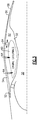
Figure 3 shows a second embodiment. -
Figure 1A shows anaircraft 17 having a fuselage 18. Apropulsor 19 is mounted within atail 20 and is driven by anengine 21 throughshaft 13, as will be explained below.Engine 21 is embedded within the fuselage 18. Aninlet 22 delivers air into aninlet duct 24 which takes the air to an inlet for theengine 21. -
Figure 1B schematically shows theengine 21. As shown, acompressor inlet 23 into the engine delivers air to acompressor 25. The air is then delivered into acombustor 27 and mixed with fuel and ignited. Products of this combustion pass downstream over aturbine rotor 29 driving it to rotate. The turbine rotor, in turn, drives the compressor rotor. Of course, this view is schematic, and many other components may be included. - The turbine rotor drives the
propulsor 19 to rotate throughshaft 13. The propulsor may be a large fan, and its output provides propulsion foraircraft 17. While a single spool is shown, a two-spool engine may be used. -
Figure 2A shows details of theengine 21 and theinlet duct 24. As shown, the radially outer air within theinlet duct 24 enters into aboundary layer inlet 26. As understood, there would be a boundary layer of air adjacent theinner surface 15 of the inlet duct, and that air is directed away from thecompressor inlet 23 leading to the compressor. -
Figure 2B shows anembodiment 12 where the air entering the boundary layer inlet passes into acooling sleeve 28 that extends generally along the entire length of theengine 21 to anoutlet 40. Atoutlet 40, air from anexhaust 30 passes downstream to pass over a tipturbine having blades 31 driving thepropulsor 19. Of course, thepropulsor 19 is shown schematically and it would include mounting structure and flow structure to deliver air as propulsion air to thepropulsor 19. While a tip turbine is disclosed, other turbine types could be used. - In such an embodiment, the cooling air may be diverted away from the gases driving the turbine.
- The boundary layer air, being tapped away from the engine, thus, does not raise concerns with regard to the efficient operation of the engine. Instead, the boundary layer air is not only directed away from the engine, but it provides a cooling function which increases the efficiency of the overall engine.
-
Figure 3 shows anembodiment 50 wherein theinlet 52 into thecooling sleeve 54 passes downstream, however, thedownstream end 56 is closed off. Instead, there are engine externals, such as engine accessories, mounted within achamber 62. Thischamber 62 desirably receives air which is changed periodically. In this embodiment,inlet conduits 64 deliver air from the coolingsleeve 54 into thechamber 62. That air is driven outwardly of anexit 58, where it also mixes with the products of combustion to drive the tip turbine for the propulsor as in the prior embodiment. - As shown in
Figure 2B andFigure 3 ,inner housing 32 surrounds the components of the engine. A chamber 33 (or 62) is defined outwardly ofinner housing 32 and inwardly of the coolingsleeve 28. Thechamber 33 may contain engine accessories, such as controls, pumps, etc. - Although an embodiment of this invention has been disclosed, a worker of ordinary skill in this art would recognize that certain modifications would come within the scope of this invention. For that reason, the following claims should be studied to determine the true scope and content of this invention.
Claims (8)
- A gas turbine engine (21) comprising:an inner housing surrounding a compressor (25), a combustor (27), and a turbine (29), with a compressor inlet (23) leading into said compressor (25), and a cooling sleeve (26) defined radially outwardly of said compressor inlet (23) to said compressor (25), for receiving cooling air radially outward of said compressor inlet (23), said cooling sleeve (26) extending along a length of said engine (21), and radially outwardly of said inner housing, with said cooling air in said cooling sleeve (26) being ejected at a downstream end to mix with products of combustion downstream of the turbine (29).
- The gas turbine engine (21) as set forth in claim 1, wherein said mixed air drives a propulsor turbine (31) for driving a propulsor (19) positioned downstream of said turbine (29).
- The gas turbine engine (21) as set forth in claim 2, wherein said propulsor turbine (31) is a tip turbine, with turbine blades being formed at an outer periphery of said propulsor (19), to be driven to rotate by the products of combustion and, in turn, rotate the propulsor (19).
- The gas turbine engine (21) as set forth in claim 1, wherein the turbine drives a propulsor (19) through a shaft (31).
- The gas turbine engine (21) as set forth in any preceding claim, wherein said cooling air in said cooling sleeve (28) provides cooling air to at least one component in a chamber (62) positioned radially between a radially outer surface on said inner housing (32) and a radially inner surface of said cooling sleeve (28).
- The gas turbine engine (21) as set forth in claim 5, wherein said chamber (62) receives cooling air from said cooling sleeve (28) directed into said chamber (62) through at least one conduit (64).
- The gas turbine engine (21) as set forth in any preceding claim, wherein an elongated inlet duct (24) delivers air into said compressor inlet (23), and further delivers boundary layer air into an inlet of said cooling sleeve (28).
- An aircraft (17) comprising:an aircraft fuselage (18); andthe gas turbine engine (21) of any preceding claim embedded in said fuselage (18).
Applications Claiming Priority (1)
| Application Number | Priority Date | Filing Date | Title |
|---|---|---|---|
| US15/217,108 US10934938B2 (en) | 2016-07-22 | 2016-07-22 | Boundary layer cooling air for embedded engine |
Publications (2)
| Publication Number | Publication Date |
|---|---|
| EP3273030A1 true EP3273030A1 (en) | 2018-01-24 |
| EP3273030B1 EP3273030B1 (en) | 2021-03-24 |
Family
ID=59409179
Family Applications (1)
| Application Number | Title | Priority Date | Filing Date |
|---|---|---|---|
| EP17182673.8A Active EP3273030B1 (en) | 2016-07-22 | 2017-07-21 | Embedded engine using boundary layer cooling air |
Country Status (2)
| Country | Link |
|---|---|
| US (1) | US10934938B2 (en) |
| EP (1) | EP3273030B1 (en) |
Families Citing this family (2)
| Publication number | Priority date | Publication date | Assignee | Title |
|---|---|---|---|---|
| FR3060531B1 (en) * | 2016-12-20 | 2019-05-31 | Airbus Operations | REAR AIRCRAFT PART COMPRISING A FUSELAGE FRAME SUPPORTING TWO PARTIALLY BITTED ENGINES |
| GB202312225D0 (en) * | 2023-08-10 | 2023-09-27 | Rolls Royce Plc | Airframe assembly |
Citations (6)
| Publication number | Priority date | Publication date | Assignee | Title |
|---|---|---|---|---|
| US20050252193A1 (en) * | 2004-04-22 | 2005-11-17 | The Boeing Company | System and method for controlling the temperature and infrared signature of an engine |
| US20060242941A1 (en) * | 2005-04-29 | 2006-11-02 | General Electric Company | Fladed supersonic missile turbojet |
| US20090000305A1 (en) * | 2006-01-19 | 2009-01-01 | Airbus France | Dual Flow Turbine Engine Equipped with a Precooler |
| US20110277483A1 (en) * | 2008-12-31 | 2011-11-17 | Syed Jalaluddin Khalid | Gas turbine engine with ejector |
| US8365514B1 (en) * | 2012-02-27 | 2013-02-05 | United Technologies Corporation | Hybrid turbofan engine |
| US20140208714A1 (en) * | 2012-12-19 | 2014-07-31 | United Technologies Corporation | Thermal Management for Gas Turbine Engine |
Family Cites Families (6)
| Publication number | Priority date | Publication date | Assignee | Title |
|---|---|---|---|---|
| US5357742A (en) * | 1993-03-12 | 1994-10-25 | General Electric Company | Turbojet cooling system |
| US6202403B1 (en) * | 1998-12-22 | 2001-03-20 | General Electric Company | Core compartment valve cooling valve scheduling |
| US7721260B2 (en) | 2004-09-08 | 2010-05-18 | Kozio, Inc. | Embedded Test I/O Engine |
| FR2937952B1 (en) * | 2008-10-30 | 2010-12-17 | Snecma | AIRCRAFT WITH PARTIALLY INTEGRATED ENGINES IN FUSELAGE |
| EP2610164B1 (en) | 2011-12-28 | 2015-10-28 | Airbus Operations S.L. | Rear fuselage with a shield for an aircraft with fuselage-mounted engines and method for determining the area of the shield |
| EP2969759B1 (en) * | 2013-03-13 | 2016-11-30 | Rolls-Royce North American Technologies, Inc. | Generator for flight vehicle |
-
2016
- 2016-07-22 US US15/217,108 patent/US10934938B2/en active Active
-
2017
- 2017-07-21 EP EP17182673.8A patent/EP3273030B1/en active Active
Patent Citations (6)
| Publication number | Priority date | Publication date | Assignee | Title |
|---|---|---|---|---|
| US20050252193A1 (en) * | 2004-04-22 | 2005-11-17 | The Boeing Company | System and method for controlling the temperature and infrared signature of an engine |
| US20060242941A1 (en) * | 2005-04-29 | 2006-11-02 | General Electric Company | Fladed supersonic missile turbojet |
| US20090000305A1 (en) * | 2006-01-19 | 2009-01-01 | Airbus France | Dual Flow Turbine Engine Equipped with a Precooler |
| US20110277483A1 (en) * | 2008-12-31 | 2011-11-17 | Syed Jalaluddin Khalid | Gas turbine engine with ejector |
| US8365514B1 (en) * | 2012-02-27 | 2013-02-05 | United Technologies Corporation | Hybrid turbofan engine |
| US20140208714A1 (en) * | 2012-12-19 | 2014-07-31 | United Technologies Corporation | Thermal Management for Gas Turbine Engine |
Also Published As
| Publication number | Publication date |
|---|---|
| US20180023474A1 (en) | 2018-01-25 |
| EP3273030B1 (en) | 2021-03-24 |
| US10934938B2 (en) | 2021-03-02 |
Similar Documents
| Publication | Publication Date | Title |
|---|---|---|
| JP6030940B2 (en) | System and method for active clearance control | |
| US9878796B2 (en) | Hybrid drive for gas turbine engine | |
| US9163562B2 (en) | Constant speed pump system for engine ECS loss elimination | |
| EP2915988B1 (en) | Offset core engine architecture | |
| US10196982B2 (en) | Gas turbine engine having a flow control surface with a cooling conduit | |
| EP3284942A1 (en) | Direct drive aft fan engine | |
| US10641124B2 (en) | Hybrid electric turbine engine | |
| EP3406519A1 (en) | Dedicated fans for boundary layer ingestion | |
| US9989011B2 (en) | Reverse flow single spool core gas turbine engine | |
| CN107013268A (en) | Compression radome fairing for jet engine exhaust | |
| GB1127659A (en) | Improvements in gas turbine engines | |
| RU2522208C1 (en) | Gas turbine engine pylon assembly and gas turbine engine system | |
| EP3273030A1 (en) | Embedded engine using boundary layer cooling air | |
| EP2924247A1 (en) | Hybrid drive for gas turbine engine | |
| US10393019B2 (en) | Assembly and method for influencing flow through a fan of a gas turbine engine | |
| EP3019716B1 (en) | Angled core engine | |
| EP4484740A1 (en) | Cooling flow injection to alter exhaust boundary conditions in a turbo-compounded engine | |
| EP2981696B1 (en) | Gas turbine engine having a bifurcated air inlet housing | |
| EP2904209B1 (en) | Bi-directional compression fan rotor for a gas turbine engine | |
| US12326112B2 (en) | Gas turbine engine bypass louver and baffle rib design | |
| RU2634444C1 (en) | Device for starting gas turbine engine | |
| US10174680B2 (en) | Gas turbine engine with distributed fans and bypass air mixer |
Legal Events
| Date | Code | Title | Description |
|---|---|---|---|
| PUAI | Public reference made under article 153(3) epc to a published international application that has entered the european phase |
Free format text: ORIGINAL CODE: 0009012 |
|
| STAA | Information on the status of an ep patent application or granted ep patent |
Free format text: STATUS: THE APPLICATION HAS BEEN PUBLISHED |
|
| AK | Designated contracting states |
Kind code of ref document: A1 Designated state(s): AL AT BE BG CH CY CZ DE DK EE ES FI FR GB GR HR HU IE IS IT LI LT LU LV MC MK MT NL NO PL PT RO RS SE SI SK SM TR |
|
| AX | Request for extension of the european patent |
Extension state: BA ME |
|
| STAA | Information on the status of an ep patent application or granted ep patent |
Free format text: STATUS: REQUEST FOR EXAMINATION WAS MADE |
|
| 17P | Request for examination filed |
Effective date: 20180724 |
|
| RBV | Designated contracting states (corrected) |
Designated state(s): AL AT BE BG CH CY CZ DE DK EE ES FI FR GB GR HR HU IE IS IT LI LT LU LV MC MK MT NL NO PL PT RO RS SE SI SK SM TR |
|
| STAA | Information on the status of an ep patent application or granted ep patent |
Free format text: STATUS: EXAMINATION IS IN PROGRESS |
|
| 17Q | First examination report despatched |
Effective date: 20181207 |
|
| RIN1 | Information on inventor provided before grant (corrected) |
Inventor name: SUCIU, GABRIEL L. Inventor name: CHANDLER, JESSE M. Inventor name: ZYSMAN, STEVEN H. Inventor name: LORD, WESLEY K. |
|
| GRAP | Despatch of communication of intention to grant a patent |
Free format text: ORIGINAL CODE: EPIDOSNIGR1 |
|
| STAA | Information on the status of an ep patent application or granted ep patent |
Free format text: STATUS: GRANT OF PATENT IS INTENDED |
|
| INTG | Intention to grant announced |
Effective date: 20201006 |
|
| GRAS | Grant fee paid |
Free format text: ORIGINAL CODE: EPIDOSNIGR3 |
|
| GRAA | (expected) grant |
Free format text: ORIGINAL CODE: 0009210 |
|
| STAA | Information on the status of an ep patent application or granted ep patent |
Free format text: STATUS: THE PATENT HAS BEEN GRANTED |
|
| AK | Designated contracting states |
Kind code of ref document: B1 Designated state(s): AL AT BE BG CH CY CZ DE DK EE ES FI FR GB GR HR HU IE IS IT LI LT LU LV MC MK MT NL NO PL PT RO RS SE SI SK SM TR |
|
| RAP1 | Party data changed (applicant data changed or rights of an application transferred) |
Owner name: RAYTHEON TECHNOLOGIES CORPORATION |
|
| REG | Reference to a national code |
Ref country code: GB Ref legal event code: FG4D |
|
| REG | Reference to a national code |
Ref country code: CH Ref legal event code: EP |
|
| REG | Reference to a national code |
Ref country code: DE Ref legal event code: R096 Ref document number: 602017035098 Country of ref document: DE |
|
| REG | Reference to a national code |
Ref country code: IE Ref legal event code: FG4D |
|
| REG | Reference to a national code |
Ref country code: AT Ref legal event code: REF Ref document number: 1374718 Country of ref document: AT Kind code of ref document: T Effective date: 20210415 |
|
| REG | Reference to a national code |
Ref country code: LT Ref legal event code: MG9D |
|
| PG25 | Lapsed in a contracting state [announced via postgrant information from national office to epo] |
Ref country code: FI Free format text: LAPSE BECAUSE OF FAILURE TO SUBMIT A TRANSLATION OF THE DESCRIPTION OR TO PAY THE FEE WITHIN THE PRESCRIBED TIME-LIMIT Effective date: 20210324 Ref country code: HR Free format text: LAPSE BECAUSE OF FAILURE TO SUBMIT A TRANSLATION OF THE DESCRIPTION OR TO PAY THE FEE WITHIN THE PRESCRIBED TIME-LIMIT Effective date: 20210324 Ref country code: GR Free format text: LAPSE BECAUSE OF FAILURE TO SUBMIT A TRANSLATION OF THE DESCRIPTION OR TO PAY THE FEE WITHIN THE PRESCRIBED TIME-LIMIT Effective date: 20210625 Ref country code: NO Free format text: LAPSE BECAUSE OF FAILURE TO SUBMIT A TRANSLATION OF THE DESCRIPTION OR TO PAY THE FEE WITHIN THE PRESCRIBED TIME-LIMIT Effective date: 20210624 Ref country code: BG Free format text: LAPSE BECAUSE OF FAILURE TO SUBMIT A TRANSLATION OF THE DESCRIPTION OR TO PAY THE FEE WITHIN THE PRESCRIBED TIME-LIMIT Effective date: 20210624 |
|
| PG25 | Lapsed in a contracting state [announced via postgrant information from national office to epo] |
Ref country code: SE Free format text: LAPSE BECAUSE OF FAILURE TO SUBMIT A TRANSLATION OF THE DESCRIPTION OR TO PAY THE FEE WITHIN THE PRESCRIBED TIME-LIMIT Effective date: 20210324 Ref country code: RS Free format text: LAPSE BECAUSE OF FAILURE TO SUBMIT A TRANSLATION OF THE DESCRIPTION OR TO PAY THE FEE WITHIN THE PRESCRIBED TIME-LIMIT Effective date: 20210324 Ref country code: LV Free format text: LAPSE BECAUSE OF FAILURE TO SUBMIT A TRANSLATION OF THE DESCRIPTION OR TO PAY THE FEE WITHIN THE PRESCRIBED TIME-LIMIT Effective date: 20210324 |
|
| REG | Reference to a national code |
Ref country code: NL Ref legal event code: MP Effective date: 20210324 |
|
| REG | Reference to a national code |
Ref country code: AT Ref legal event code: MK05 Ref document number: 1374718 Country of ref document: AT Kind code of ref document: T Effective date: 20210324 |
|
| PG25 | Lapsed in a contracting state [announced via postgrant information from national office to epo] |
Ref country code: NL Free format text: LAPSE BECAUSE OF FAILURE TO SUBMIT A TRANSLATION OF THE DESCRIPTION OR TO PAY THE FEE WITHIN THE PRESCRIBED TIME-LIMIT Effective date: 20210324 |
|
| PG25 | Lapsed in a contracting state [announced via postgrant information from national office to epo] |
Ref country code: AT Free format text: LAPSE BECAUSE OF FAILURE TO SUBMIT A TRANSLATION OF THE DESCRIPTION OR TO PAY THE FEE WITHIN THE PRESCRIBED TIME-LIMIT Effective date: 20210324 Ref country code: SM Free format text: LAPSE BECAUSE OF FAILURE TO SUBMIT A TRANSLATION OF THE DESCRIPTION OR TO PAY THE FEE WITHIN THE PRESCRIBED TIME-LIMIT Effective date: 20210324 Ref country code: EE Free format text: LAPSE BECAUSE OF FAILURE TO SUBMIT A TRANSLATION OF THE DESCRIPTION OR TO PAY THE FEE WITHIN THE PRESCRIBED TIME-LIMIT Effective date: 20210324 Ref country code: CZ Free format text: LAPSE BECAUSE OF FAILURE TO SUBMIT A TRANSLATION OF THE DESCRIPTION OR TO PAY THE FEE WITHIN THE PRESCRIBED TIME-LIMIT Effective date: 20210324 Ref country code: LT Free format text: LAPSE BECAUSE OF FAILURE TO SUBMIT A TRANSLATION OF THE DESCRIPTION OR TO PAY THE FEE WITHIN THE PRESCRIBED TIME-LIMIT Effective date: 20210324 |
|
| PG25 | Lapsed in a contracting state [announced via postgrant information from national office to epo] |
Ref country code: IS Free format text: LAPSE BECAUSE OF FAILURE TO SUBMIT A TRANSLATION OF THE DESCRIPTION OR TO PAY THE FEE WITHIN THE PRESCRIBED TIME-LIMIT Effective date: 20210724 Ref country code: PT Free format text: LAPSE BECAUSE OF FAILURE TO SUBMIT A TRANSLATION OF THE DESCRIPTION OR TO PAY THE FEE WITHIN THE PRESCRIBED TIME-LIMIT Effective date: 20210726 Ref country code: PL Free format text: LAPSE BECAUSE OF FAILURE TO SUBMIT A TRANSLATION OF THE DESCRIPTION OR TO PAY THE FEE WITHIN THE PRESCRIBED TIME-LIMIT Effective date: 20210324 Ref country code: RO Free format text: LAPSE BECAUSE OF FAILURE TO SUBMIT A TRANSLATION OF THE DESCRIPTION OR TO PAY THE FEE WITHIN THE PRESCRIBED TIME-LIMIT Effective date: 20210324 Ref country code: SK Free format text: LAPSE BECAUSE OF FAILURE TO SUBMIT A TRANSLATION OF THE DESCRIPTION OR TO PAY THE FEE WITHIN THE PRESCRIBED TIME-LIMIT Effective date: 20210324 |
|
| REG | Reference to a national code |
Ref country code: DE Ref legal event code: R097 Ref document number: 602017035098 Country of ref document: DE |
|
| PG25 | Lapsed in a contracting state [announced via postgrant information from national office to epo] |
Ref country code: ES Free format text: LAPSE BECAUSE OF FAILURE TO SUBMIT A TRANSLATION OF THE DESCRIPTION OR TO PAY THE FEE WITHIN THE PRESCRIBED TIME-LIMIT Effective date: 20210324 Ref country code: DK Free format text: LAPSE BECAUSE OF FAILURE TO SUBMIT A TRANSLATION OF THE DESCRIPTION OR TO PAY THE FEE WITHIN THE PRESCRIBED TIME-LIMIT Effective date: 20210324 Ref country code: AL Free format text: LAPSE BECAUSE OF FAILURE TO SUBMIT A TRANSLATION OF THE DESCRIPTION OR TO PAY THE FEE WITHIN THE PRESCRIBED TIME-LIMIT Effective date: 20210324 |
|
| PLBE | No opposition filed within time limit |
Free format text: ORIGINAL CODE: 0009261 |
|
| STAA | Information on the status of an ep patent application or granted ep patent |
Free format text: STATUS: NO OPPOSITION FILED WITHIN TIME LIMIT |
|
| PG25 | Lapsed in a contracting state [announced via postgrant information from national office to epo] |
Ref country code: SI Free format text: LAPSE BECAUSE OF FAILURE TO SUBMIT A TRANSLATION OF THE DESCRIPTION OR TO PAY THE FEE WITHIN THE PRESCRIBED TIME-LIMIT Effective date: 20210324 |
|
| REG | Reference to a national code |
Ref country code: CH Ref legal event code: PL |
|
| 26N | No opposition filed |
Effective date: 20220104 |
|
| PG25 | Lapsed in a contracting state [announced via postgrant information from national office to epo] |
Ref country code: MC Free format text: LAPSE BECAUSE OF FAILURE TO SUBMIT A TRANSLATION OF THE DESCRIPTION OR TO PAY THE FEE WITHIN THE PRESCRIBED TIME-LIMIT Effective date: 20210324 |
|
| REG | Reference to a national code |
Ref country code: BE Ref legal event code: MM Effective date: 20210731 |
|
| PG25 | Lapsed in a contracting state [announced via postgrant information from national office to epo] |
Ref country code: LI Free format text: LAPSE BECAUSE OF NON-PAYMENT OF DUE FEES Effective date: 20210731 Ref country code: CH Free format text: LAPSE BECAUSE OF NON-PAYMENT OF DUE FEES Effective date: 20210731 |
|
| PG25 | Lapsed in a contracting state [announced via postgrant information from national office to epo] |
Ref country code: IS Free format text: LAPSE BECAUSE OF FAILURE TO SUBMIT A TRANSLATION OF THE DESCRIPTION OR TO PAY THE FEE WITHIN THE PRESCRIBED TIME-LIMIT Effective date: 20210724 Ref country code: LU Free format text: LAPSE BECAUSE OF NON-PAYMENT OF DUE FEES Effective date: 20210721 |
|
| PG25 | Lapsed in a contracting state [announced via postgrant information from national office to epo] |
Ref country code: IE Free format text: LAPSE BECAUSE OF NON-PAYMENT OF DUE FEES Effective date: 20210721 Ref country code: BE Free format text: LAPSE BECAUSE OF NON-PAYMENT OF DUE FEES Effective date: 20210731 |
|
| PG25 | Lapsed in a contracting state [announced via postgrant information from national office to epo] |
Ref country code: IT Free format text: LAPSE BECAUSE OF FAILURE TO SUBMIT A TRANSLATION OF THE DESCRIPTION OR TO PAY THE FEE WITHIN THE PRESCRIBED TIME-LIMIT Effective date: 20210324 |
|
| PG25 | Lapsed in a contracting state [announced via postgrant information from national office to epo] |
Ref country code: HU Free format text: LAPSE BECAUSE OF FAILURE TO SUBMIT A TRANSLATION OF THE DESCRIPTION OR TO PAY THE FEE WITHIN THE PRESCRIBED TIME-LIMIT; INVALID AB INITIO Effective date: 20170721 |
|
| P01 | Opt-out of the competence of the unified patent court (upc) registered |
Effective date: 20230520 |
|
| PG25 | Lapsed in a contracting state [announced via postgrant information from national office to epo] |
Ref country code: CY Free format text: LAPSE BECAUSE OF FAILURE TO SUBMIT A TRANSLATION OF THE DESCRIPTION OR TO PAY THE FEE WITHIN THE PRESCRIBED TIME-LIMIT Effective date: 20210324 |
|
| PG25 | Lapsed in a contracting state [announced via postgrant information from national office to epo] |
Ref country code: MK Free format text: LAPSE BECAUSE OF FAILURE TO SUBMIT A TRANSLATION OF THE DESCRIPTION OR TO PAY THE FEE WITHIN THE PRESCRIBED TIME-LIMIT Effective date: 20210324 |
|
| PG25 | Lapsed in a contracting state [announced via postgrant information from national office to epo] |
Ref country code: MT Free format text: LAPSE BECAUSE OF FAILURE TO SUBMIT A TRANSLATION OF THE DESCRIPTION OR TO PAY THE FEE WITHIN THE PRESCRIBED TIME-LIMIT Effective date: 20210324 |
|
| PGFP | Annual fee paid to national office [announced via postgrant information from national office to epo] |
Ref country code: GB Payment date: 20250619 Year of fee payment: 9 |
|
| PGFP | Annual fee paid to national office [announced via postgrant information from national office to epo] |
Ref country code: FR Payment date: 20250620 Year of fee payment: 9 |
|
| REG | Reference to a national code |
Ref country code: DE Ref legal event code: R081 Ref document number: 602017035098 Country of ref document: DE Owner name: RTX CORPORATION (N.D.GES.D. STAATES DELAWARE),, US Free format text: FORMER OWNER: RAYTHEON TECHNOLOGIES CORPORATION, FARMINGTON, CT, US |
|
| PGFP | Annual fee paid to national office [announced via postgrant information from national office to epo] |
Ref country code: DE Payment date: 20250620 Year of fee payment: 9 |
|
| PG25 | Lapsed in a contracting state [announced via postgrant information from national office to epo] |
Ref country code: TR Free format text: LAPSE BECAUSE OF FAILURE TO SUBMIT A TRANSLATION OF THE DESCRIPTION OR TO PAY THE FEE WITHIN THE PRESCRIBED TIME-LIMIT Effective date: 20210324 |