EP3273016A1 - Multi-engine coordination during gas turbine engine motoring - Google Patents
Multi-engine coordination during gas turbine engine motoring Download PDFInfo
- Publication number
- EP3273016A1 EP3273016A1 EP17181931.1A EP17181931A EP3273016A1 EP 3273016 A1 EP3273016 A1 EP 3273016A1 EP 17181931 A EP17181931 A EP 17181931A EP 3273016 A1 EP3273016 A1 EP 3273016A1
- Authority
- EP
- European Patent Office
- Prior art keywords
- engine
- motoring
- gas turbine
- dry motoring
- dry
- Prior art date
- Legal status (The legal status is an assumption and is not a legal conclusion. Google has not performed a legal analysis and makes no representation as to the accuracy of the status listed.)
- Granted
Links
Images



Classifications
-
- F—MECHANICAL ENGINEERING; LIGHTING; HEATING; WEAPONS; BLASTING
- F01—MACHINES OR ENGINES IN GENERAL; ENGINE PLANTS IN GENERAL; STEAM ENGINES
- F01D—NON-POSITIVE DISPLACEMENT MACHINES OR ENGINES, e.g. STEAM TURBINES
- F01D19/00—Starting of machines or engines; Regulating, controlling, or safety means in connection therewith
- F01D19/02—Starting of machines or engines; Regulating, controlling, or safety means in connection therewith dependent on temperature of component parts, e.g. of turbine-casing
-
- B—PERFORMING OPERATIONS; TRANSPORTING
- B64—AIRCRAFT; AVIATION; COSMONAUTICS
- B64D—EQUIPMENT FOR FITTING IN OR TO AIRCRAFT; FLIGHT SUITS; PARACHUTES; ARRANGEMENT OR MOUNTING OF POWER PLANTS OR PROPULSION TRANSMISSIONS IN AIRCRAFT
- B64D27/00—Arrangement or mounting of power plants in aircraft; Aircraft characterised by the type or position of power plants
- B64D27/02—Aircraft characterised by the type or position of power plants
- B64D27/10—Aircraft characterised by the type or position of power plants of gas-turbine type
- B64D27/12—Aircraft characterised by the type or position of power plants of gas-turbine type within, or attached to, wings
-
- B—PERFORMING OPERATIONS; TRANSPORTING
- B64—AIRCRAFT; AVIATION; COSMONAUTICS
- B64D—EQUIPMENT FOR FITTING IN OR TO AIRCRAFT; FLIGHT SUITS; PARACHUTES; ARRANGEMENT OR MOUNTING OF POWER PLANTS OR PROPULSION TRANSMISSIONS IN AIRCRAFT
- B64D41/00—Power installations for auxiliary purposes
-
- F—MECHANICAL ENGINEERING; LIGHTING; HEATING; WEAPONS; BLASTING
- F01—MACHINES OR ENGINES IN GENERAL; ENGINE PLANTS IN GENERAL; STEAM ENGINES
- F01D—NON-POSITIVE DISPLACEMENT MACHINES OR ENGINES, e.g. STEAM TURBINES
- F01D25/00—Component parts, details, or accessories, not provided for in, or of interest apart from, other groups
- F01D25/34—Turning or inching gear
-
- F—MECHANICAL ENGINEERING; LIGHTING; HEATING; WEAPONS; BLASTING
- F02—COMBUSTION ENGINES; HOT-GAS OR COMBUSTION-PRODUCT ENGINE PLANTS
- F02C—GAS-TURBINE PLANTS; AIR INTAKES FOR JET-PROPULSION PLANTS; CONTROLLING FUEL SUPPLY IN AIR-BREATHING JET-PROPULSION PLANTS
- F02C3/00—Gas-turbine plants characterised by the use of combustion products as the working fluid
- F02C3/04—Gas-turbine plants characterised by the use of combustion products as the working fluid having a turbine driving a compressor
-
- F—MECHANICAL ENGINEERING; LIGHTING; HEATING; WEAPONS; BLASTING
- F02—COMBUSTION ENGINES; HOT-GAS OR COMBUSTION-PRODUCT ENGINE PLANTS
- F02C—GAS-TURBINE PLANTS; AIR INTAKES FOR JET-PROPULSION PLANTS; CONTROLLING FUEL SUPPLY IN AIR-BREATHING JET-PROPULSION PLANTS
- F02C6/00—Plural gas-turbine plants; Combinations of gas-turbine plants with other apparatus; Adaptations of gas-turbine plants for special use
- F02C6/20—Adaptations of gas-turbine plants for driving vehicles
-
- F—MECHANICAL ENGINEERING; LIGHTING; HEATING; WEAPONS; BLASTING
- F02—COMBUSTION ENGINES; HOT-GAS OR COMBUSTION-PRODUCT ENGINE PLANTS
- F02C—GAS-TURBINE PLANTS; AIR INTAKES FOR JET-PROPULSION PLANTS; CONTROLLING FUEL SUPPLY IN AIR-BREATHING JET-PROPULSION PLANTS
- F02C7/00—Features, components parts, details or accessories, not provided for in, or of interest apart form groups F02C1/00 - F02C6/00; Air intakes for jet-propulsion plants
- F02C7/26—Starting; Ignition
- F02C7/268—Starting drives for the rotor, acting directly on the rotor of the gas turbine to be started
- F02C7/275—Mechanical drives
- F02C7/277—Mechanical drives the starter being a separate turbine
-
- F—MECHANICAL ENGINEERING; LIGHTING; HEATING; WEAPONS; BLASTING
- F02—COMBUSTION ENGINES; HOT-GAS OR COMBUSTION-PRODUCT ENGINE PLANTS
- F02C—GAS-TURBINE PLANTS; AIR INTAKES FOR JET-PROPULSION PLANTS; CONTROLLING FUEL SUPPLY IN AIR-BREATHING JET-PROPULSION PLANTS
- F02C9/00—Controlling gas-turbine plants; Controlling fuel supply in air- breathing jet-propulsion plants
-
- B—PERFORMING OPERATIONS; TRANSPORTING
- B64—AIRCRAFT; AVIATION; COSMONAUTICS
- B64D—EQUIPMENT FOR FITTING IN OR TO AIRCRAFT; FLIGHT SUITS; PARACHUTES; ARRANGEMENT OR MOUNTING OF POWER PLANTS OR PROPULSION TRANSMISSIONS IN AIRCRAFT
- B64D41/00—Power installations for auxiliary purposes
- B64D2041/002—Mounting arrangements for auxiliary power units (APU's)
-
- B—PERFORMING OPERATIONS; TRANSPORTING
- B64—AIRCRAFT; AVIATION; COSMONAUTICS
- B64F—GROUND OR AIRCRAFT-CARRIER-DECK INSTALLATIONS SPECIALLY ADAPTED FOR USE IN CONNECTION WITH AIRCRAFT; DESIGNING, MANUFACTURING, ASSEMBLING, CLEANING, MAINTAINING OR REPAIRING AIRCRAFT, NOT OTHERWISE PROVIDED FOR; HANDLING, TRANSPORTING, TESTING OR INSPECTING AIRCRAFT COMPONENTS, NOT OTHERWISE PROVIDED FOR
- B64F1/00—Ground or aircraft-carrier-deck installations
- B64F1/34—Ground or aircraft-carrier-deck installations for starting propulsion plant
-
- F—MECHANICAL ENGINEERING; LIGHTING; HEATING; WEAPONS; BLASTING
- F05—INDEXING SCHEMES RELATING TO ENGINES OR PUMPS IN VARIOUS SUBCLASSES OF CLASSES F01-F04
- F05D—INDEXING SCHEME FOR ASPECTS RELATING TO NON-POSITIVE-DISPLACEMENT MACHINES OR ENGINES, GAS-TURBINES OR JET-PROPULSION PLANTS
- F05D2220/00—Application
- F05D2220/30—Application in turbines
- F05D2220/32—Application in turbines in gas turbines
- F05D2220/323—Application in turbines in gas turbines for aircraft propulsion, e.g. jet engines
-
- F—MECHANICAL ENGINEERING; LIGHTING; HEATING; WEAPONS; BLASTING
- F05—INDEXING SCHEMES RELATING TO ENGINES OR PUMPS IN VARIOUS SUBCLASSES OF CLASSES F01-F04
- F05D—INDEXING SCHEME FOR ASPECTS RELATING TO NON-POSITIVE-DISPLACEMENT MACHINES OR ENGINES, GAS-TURBINES OR JET-PROPULSION PLANTS
- F05D2220/00—Application
- F05D2220/50—Application for auxiliary power units (APU's)
-
- F—MECHANICAL ENGINEERING; LIGHTING; HEATING; WEAPONS; BLASTING
- F05—INDEXING SCHEMES RELATING TO ENGINES OR PUMPS IN VARIOUS SUBCLASSES OF CLASSES F01-F04
- F05D—INDEXING SCHEME FOR ASPECTS RELATING TO NON-POSITIVE-DISPLACEMENT MACHINES OR ENGINES, GAS-TURBINES OR JET-PROPULSION PLANTS
- F05D2260/00—Function
- F05D2260/85—Starting
-
- F—MECHANICAL ENGINEERING; LIGHTING; HEATING; WEAPONS; BLASTING
- F05—INDEXING SCHEMES RELATING TO ENGINES OR PUMPS IN VARIOUS SUBCLASSES OF CLASSES F01-F04
- F05D—INDEXING SCHEME FOR ASPECTS RELATING TO NON-POSITIVE-DISPLACEMENT MACHINES OR ENGINES, GAS-TURBINES OR JET-PROPULSION PLANTS
- F05D2270/00—Control
- F05D2270/30—Control parameters, e.g. input parameters
- F05D2270/303—Temperature
Definitions
- This disclosure relates to gas turbine engines, and more particularly to systems and methods for multi-engine coordination during gas turbine engine motoring.
- Gas turbine engines are used in numerous applications, one of which is for providing thrust to an airplane.
- the gas turbine engine of an airplane has been shut off for example, after an airplane has landed at an airport, the engine is hot and due to heat rise, the upper portions of the engine will be hotter than lower portions of the engine. When this occurs thermal expansion may cause deflection of components of the engine which may result in a "bowed rotor" condition. If a gas turbine engine is in such a bowed rotor condition it is undesirable to restart or start the engine.
- One approach to mitigating a bowed rotor condition is to use a starter system to drive rotation of a spool within the engine for an extended period of time at a speed below which a resonance occurs (i.e., a critical speed or frequency) that may lead to damage when a sufficiently large bowed rotor condition is present. Motoring is typically performed separately for each engine at different times, which extends the total start time for a multi-engine aircraft.
- a system for multi-engine coordination of gas turbine engine motoring in an aircraft.
- the system includes a controller operable to determine a motoring mode as a selection between a single engine dry motoring mode and a multi-engine dry motoring mode based on at least one temperature of a plurality of gas turbine engines and initiate dry motoring based on the motoring mode.
- the at least one temperature may be a measured core engine temperature or an oil temperature.
- dry motoring may be inhibited when the aircraft is not on the ground.
- the motoring mode may be further determined based on a plurality of performance parameters that are based on one or more of: an ambient condition, performance limitations of a compressed air source and each air turbine starter driven by the compressed air source, engine drag, and parasitic factors.
- the performance parameters may be determined based on one or more of: an ambient air temperature, an ambient pressure, and an oil temperature.
- the compressed air source may be an auxiliary power unit of the aircraft, a ground cart, or a cross engine bleed.
- the controller may be further operable to monitor a speed of each of the gas turbine engines when dry motoring is active and switch from the multi-engine dry motoring mode to the single engine dry motoring mode based on one or more of the gas turbine engines failing to reach or maintain a dry motoring threshold speed for a predetermined time limit.
- the dry motoring threshold speed may be dynamically adjusted to match a dry motoring profile.
- a system of an aircraft includes a compressed air source operable to supply compressed air, a first engine system, a second engine system, and at least one engine control interface.
- the first engine system includes a first gas turbine engine, a first air turbine starter, a first starter air valve, and a first controller operable to command the first starter air valve to control delivery of the compressed air to the first air turbine starter during motoring of the first gas turbine engine.
- the second engine system includes a second gas turbine engine, a second air turbine starter, a second starter air valve, and a second controller operable to command the second starter air valve to control delivery of the compressed air to the second air turbine starter during motoring of the second gas turbine engine.
- the at least one engine control interface is operable to determine a motoring mode as a selection between a single engine dry motoring mode and a multi-engine dry motoring mode based on at least one temperature of the first and second gas turbine engines and initiate dry motoring based on the motoring mode.
- the at least one engine control interface may be further operable to monitor a speed of the first and second gas turbine engines when dry motoring is active and switch from the multi-engine dry motoring mode to the single engine dry motoring mode based on the first or second gas turbine engine failing to reach or maintain a dry motoring threshold speed for a predetermined time limit.
- Another embodiment includes a method for multi-engine coordination during gas turbine engine motoring.
- the method includes receiving, by a controller, at least one temperature of a plurality of gas turbine engines.
- the controller determines a motoring mode as a selection between a single engine dry motoring mode and a multi-engine dry motoring mode based on the at least one temperature of the plurality of gas turbine engines. Dry motoring is initiated based on the motoring mode.
- further embodiments may include monitoring a speed of each of the gas turbine engines when dry motoring is active, and switching from the multi-engine dry motoring mode to the single engine dry motoring mode based on one or more of the gas turbine engines failing to reach or maintain a dry motoring threshold speed for a predetermined time limit.
- a technical effect of the apparatus, systems and methods is achieved by using coordinated multi-engine control for bowed rotor mitigation of gas turbine engines as described herein.
- Embodiments are related to a bowed rotor start mitigation system in a gas turbine engine.
- Embodiments can include using a starter air valve to control a rotor speed of a starting spool of a gas turbine engine to mitigate a bowed rotor condition using a dry motoring process.
- the starter air valve can be actively adjusted to deliver air pressure (i.e., compressed air) from an air supply to an air turbine starter of an engine starting system that controls starting spool rotor speed.
- Dry motoring may be performed by running an engine starting system at a lower speed with a longer duration than typically used for engine starting while dynamically adjusting the starter air valve to maintain the rotor speed and/or follow a dry motoring profile.
- Some embodiments increase the rotor speed of the starting spool to approach a critical rotor speed gradually and as thermal distortion is decreased they then accelerate beyond the critical rotor speed to complete the engine starting process.
- the critical rotor speed refers to a major resonance speed where, if the temperatures are unhomogenized, the combination of a bowed rotor and similarly bowed casing and the resonance would lead to high amplitude oscillation in the rotor and high rubbing of blade tips on one side of the rotor, especially in the high pressure compressor if the rotor is straddle-mounted.
- a dry motoring profile for dry motoring can be selected based on various parameters, such as a modelled temperature value of the gas turbine engine used to estimate heat stored in the engine core when a start sequence is initiated and identify a risk of a bowed rotor.
- the modelled temperature value alone or in combination with other values (e.g., measured temperatures) can be used to calculate a bowed rotor risk parameter.
- the modelled temperature can be adjusted relative to an ambient temperature when calculating the bowed rotor risk parameter.
- the bowed rotor risk parameter may be used to take a control action to mitigate the risk of starting the gas turbine engine with a bowed rotor.
- the control action can include dry motoring consistent with the dry motoring profile.
- a targeted rotor speed profile of the dry motoring profile can be adjusted as dry motoring is performed.
- a full authority digital engine control (FADEC) system or other system may send a message to the cockpit to inform the crew of an extended time start time due to bowed rotor mitigation actions prior to completing an engine start sequence. If the engine is in a ground test or in a test stand, a message can be sent to the test stand or cockpit based on the control-calculated risk of a bowed rotor.
- a test stand crew can be alerted regarding a requirement to keep the starting spool of the engine to a speed below the known resonance speed of the rotor in order to homogenize the temperature of the rotor and the casings about the rotor which also are distorted by temperature non-uniformity.
- Respective FADECs for each engine can provide parameters to one or more engine control interfaces including sensed temperatures and other values that may impact mode selection decisions for enabling single engine or multi-engine cranking for dry motoring.
- An engine control interface that receives the parameters can determine present conditions with respect to an operating envelope of a compressed air source and the starting system of each engine based on predetermined performance constraints, engine drag, and/or parasitic factors.
- Multi-engine cranking e.g., dual engine cranking
- the engine control interface can continue monitoring performance of the engines during dry motoring and switch to single engine cranking upon determining that the engines are not reaching the targeted speed for a predetermined period of time.
- Engine systems 100A, 100B include gas turbine engines 10A, 10B and engine starting systems 101 A, 101 B respectively.
- Engine systems 100A, 100B also include FADECs 102A, 102B to control gas turbine engines 10A, 10B and starting systems 101A, 101B.
- FADECs 102A, 102B may generally be referred to as controllers.
- FADECs 102A, 102B can communicate with respective engine control interfaces 105A, 105B using a digital communication bus 106.
- the engine control interfaces 105A, 105B can buffer engine system communication from aircraft level communication.
- the engine control interfaces 105A, 105B are integrated with the FADECs 102A, 102B.
- the engine control interfaces 105A, 105B may also be referred to as controllers when configured to make mode selection determinations to perform single engine or multi-engine dry motoring for the aircraft 5.
- the FADECs 102A, 102B and engine control interfaces 105A, 105B may each include memory to store instructions that are executed by one or more processors on one or more channels.
- the executable instructions may be stored or organized in any manner and at any level of abstraction, such as in connection with a controlling and/or monitoring operation of the gas turbine engines 10A, 10B of FIG. 1 .
- the one or more processors can be any type of central processing unit (CPU), including a general purpose processor, a digital signal processor (DSP), a microcontroller, an application specific integrated circuit (ASIC), a field programmable gate array (FPGA), or the like.
- the memory may include random access memory (RAM), read only memory (ROM), or other electronic, optical, magnetic, or any other computer readable medium onto which is stored data and control algorithms in a non-transitory form.
- an auxiliary power unit (APU) 113 and compressor 115 provide a compressed air source 114 to drive air turbine starters 120A, 120B of engine starting systems 101A, 101 B.
- Compressed air from the compressed air source 114 is routed through ducts 117 and air starter valves 116A, 116B to the air turbine starters 120A, 120B.
- Various shutoff valves can also be included in ducts 117, such as a main shutoff valve 119 and engine shutoff valves 121A, 121B.
- One or more bleed valves 123 can be used to release compressed air from the ducts 117.
- dry motoring can be performed simultaneously for engine systems 100A, 100B, where compressed air from the compressed air source 114 is provided to both air turbine starters 120A, 120B at the same time.
- compressed air from the compressed air source 114 is provided to both air turbine starters 120A, 120B at the same time.
- a disturbance or pressure surge of compressed air may be experienced at the starter air valve 116A, 116B and air turbine starter 120A, 120B of the engine system 100A, 100B still performing dry motoring.
- the FADECs 102A, 102B can be configured with control laws to maintain a motoring speed below a threshold level (i.e., the critical rotor speed) for the engine system 100A, 100B while performing dry motoring based on compressed air source 114.
- FADECs 102A, 102B can observe various engine parameters and starting system parameters to actively control dry motoring and prevent fault conditions from damaging the gas turbine engines 10A, 10B.
- FADECs 102A, 102B can observe engine speeds (N2) of gas turbine engines 10A, 10B and may receive starter system parameters such as starter speeds (NS) and/or starter air pressures (SAP).
- FADECs 102A, 102B can adjust starter air valves 116A, 116B based on measured feedback to reject disturbances attributable to dual to single or single to dual engine starting transitions, such as switching from dry motoring both gas turbine engines 10A, 10B to dry motoring either gas turbine engine 10A or 10B.
- the FADECs 102A, 102B can provide either or both of the engine control interfaces 105A, 105B with engine data including parameters that directly or indirectly modify an aspect of the compressed air received at the starter air valves 116A, 116B.
- Engine data can be sent on the digital communication bus 106 to either or both of the engine control interfaces 105A, 105B to make single engine/multi-engine cranking determinations.
- Engine data may include fault information, such as a detected failure of the starter air valves 116A, 116B and/or the air turbine starters 120A, 120B.
- Present condition information and/or commands included in the engine data can allow the engine control interfaces 105A, 105B to track and/or predict events that will impact available compressed air for dry motoring at each of the engine starting systems 101 A, 101 B.
- at least one temperature of gas turbine engines 10A, 10B such as a measured core engine temperature or an oil temperature, can be used to determine current conditions and select a multi-engine dry motoring envelope which can be used to identify present multi-engine dry motoring capability (e.g., whether a dry motoring threshold speed can be reached by two or more engines 10A, 10B at the same time).
- Additional performance parameters such as an ambient air temperature and/or an ambient pressure, can also be used to determine whether a dry motoring threshold speed can be reached. For instance, ambient temperature can be used for temperature comparison/normalization and ambient pressure can be used to adjust for altitude effects.
- FIG. 1 depicts one example configuration, it will be understood that embodiments as described herein can cover a wide range of configurations, such as a four engine system.
- the compressed air source 114 can include multiple sources other than APU 113 and compressor 115, such as a ground cart or cross engine bleed air.
- the digital communication bus 106 can include an aircraft, engine, and/or test stand communication bus to interface with FADECs 102A, 102B, engine control interfaces 105A, 105B, aircraft controls, e.g., a cockpit, various onboard computer systems, and/or a test stand (not depicted).
- Either or both channels of FADECs 102A, 102B can alternate on and off commands to respective electromechanical devices 110A, 110B coupled to starter air valves 116A, 116B to achieve a partially open position of the starter air valves 116A, 116B to control a flow of compressed air from compressed air source 114 (e.g., APU 113 and compressor 115 of FIG. 1 ) as a starter air flow to air turbine starters 120A, 120B during dry motoring.
- compressed air source 114 e.g., APU 113 and compressor 115 of FIG. 1
- the air turbine starters 120A, 120B output torque to drive rotation of respective gas turbine engine shafts 50A, 50B of starting spools of the gas turbine engines 10A, 10B.
- the FADECs 102A, 102B can monitor engine speed (N2), starter speed (NS), starter air pressure (SAP), and/or other engine parameters to determine an engine operating state and control the starter air valves 116A, 116B.
- the FADECs 102A, 102B can each establish a control loop with respect to a motoring speed (N2 and/or NS) and/or starter air pressure to adjust positioning of the starter air valves 116A, 116B.
- the FADECs 102A, 102B can also transmit engine data on digital communication bus 106 to engine control interfaces 105A, 105B, including present conditions and commands of each engine system 100A, 100B that may impact characteristics of the compressed air available at the starter air valves 116A, 116B.
- the starter air valves 116A, 116B are discrete valves designed as on/off valves that are typically commanded to either fully opened or fully closed. However, there is a time lag to achieve the fully open position and the fully closed position.
- intermediate positioning states i.e., partially opened/closed
- the FADECs 102A, 120B can modulate the on and off commands (e.g., as a duty cycle using pulse width modulation) to the electromechanical devices 110A, 110B to further open the starter air valves 116A, 116B and increase a rotational speed of the gas turbine engine shafts 50A, 50B.
- the electromechanical devices 110A, 110B have a cycle time defined between an off-command to an on-command to the off-command that is at most half of a movement time for the starter air valves 116A, 116B to transition from fully closed to fully open.
- Pneumatic lines or mechanical linkage (not depicted) can be used to drive the starter air valves 116A, 116B between the open position and the closed position.
- the electromechanical devices 110A, 110B can each be a solenoid that positions the starter air valves 116A, 116B based on intermittently supplied electric power as commanded by the FADECs 102A, 102B.
- the electromechanical devices 110A, 110B are electric valves controlling muscle air to adjust the position of the starter air valves 116A, 116B as commanded by the FADECs 102A, 102B.
- the starter air valves 116A, 116B can be variable position valves that are dynamically adjustable to selected valve angles by the FADECs 102A, 102B.
- the starter air valves 116A, 116B can be continuous/infinitely adjustable and hold a commanded valve angle, which may be expressed in terms of a percentage open/closed and/or an angular value (e.g., degrees or radians). Performance parameters of the starter air valves 116A, 116B can be selected to meet dynamic response requirements.
- the starter air valves 116A, 116B each have a response rate of 0% to 100% open in less than 40 seconds. In other embodiments, the starter air valves 116A, 116B each have a response rate of 0% to 100% open in less than 30 seconds. In further embodiments, the starter air valves 116A, 116B each have a response rate of 0% to 100% open in less than 20 seconds.
- the FADECs 102A, 102B can each monitor a valve angle of the starter air valves 116A, 116B when valve angle feedback is available.
- the FADECs 102A, 102B can establish an outer control loop with respect to motoring speed and an inner control loop with respect to the valve angle of the starter air valves 116A, 116B.
- Valve angle feedback and/or valve commands can be included in the cross engine data exchanged between the FADECs 102A, 102B.
- FIG. 3 and 4 depict two example engine configurations of the gas turbine engines 10A, 10B of FIG. 1 .
- FIG. 3 is an example of a straddle-mounted spool 32A as a starting spool configuration.
- This configuration places two bearing compartments 37A and 39A (which may include a ball bearing and a roller bearing respectively), outside of the plane of most of the compressor disks of high pressure compressor 52A and at outside at least one of the turbine disks of high pressure turbine 54A.
- other embodiments may be implemented using an over-hung mounted spool 32B as depicted in FIG. 4 as a starting spool configuration.
- a bearing compartment 37B is located forward of the first turbine disk of high pressure turbine 54B such that the high pressure turbine 54B is overhung, and it is physically located aft of its main supporting structure.
- the use of straddle-mounted spools has advantages and disadvantages in the design of a gas turbine, but one characteristic of the straddle-mounted design is that the span between the bearing compartments 37A and 39A is long, making the amplitude of the high spot of a bowed rotor greater and the resonance speed that cannot be transited prior to temperature homogenization is lower.
- the straddle mounted arrangement such as straddle-mounted spool 32A
- the overhung mounted arrangement such as overhung spool 32B
- Lsupport is the distance between bearings (e.g., between bearing compartments 37A and 39A or between bearing compartments 37B and 39B)
- Dhpt is the diameter of the last blade of the high pressure turbine (e.g., high pressure turbine 54A or high pressure turbine 54B).
- a straddle-mounted engine starting spool such as straddle-mounted spool 32A, with a roller bearing at bearing compartment 39A located aft of the high pressure turbine 54A may be more vulnerable to bowed rotor problems since the Lsupport/Dhpt ranges from 1.9 to 5.6.
- FIGS. 3 and 4 also illustrate an air turbine starter 120 (e.g., air turbine starter 120A or 120B of FIGS. 1 and 2 ) interfacing through gearbox 124 via a tower shaft 55 with the straddle-mounted spool 32A proximate high compressor 52A and interfacing via tower shaft 55 with the overhung mounted spool 32B proximate high compressor 52B as part of a starting system.
- the straddle-mounted spool 32A and the over-hung mounted spool 32B are both examples of a starter spool having a gas turbine engine shaft 50 driven by the air turbine starter 120, such as gas turbine engine shafts 50A, 50B driven by air turbine starters 120A, 120B of FIG. 2 .
- FIG. 5 is a block diagram of a system 200 for bowed rotor start mitigation that may control either of the starter air valves 116A, 116B of FIGS. 1 and 2 via control signals 210 in accordance with an embodiment.
- the system 200 may also be referred to as a bowed rotor start mitigation system.
- the system 200 includes an onboard model 202 operable to produce a compressor exit temperature T 3 and a compressor inlet flow W 25 of one of the gas turbine engines 10A, 10B of FIG. 1 for use by a core temperature model 204.
- the onboard model 202 is configured to synthesize or predict major temperatures and pressures throughout one of the gas turbine engines 10A, 10B of FIG.
- the onboard model 202 and core temperature model 204 are examples of a first thermal model and a second thermal model that may be separately implemented or combined as part of a controller 102 (e.g., FADECs 102A, 102B of FIG. 1 ).
- Engine parameter synthesis is performed by the onboard model 202, and the engine parameter synthesis may be performed using the technologies described in U.S. Patent Publication No. 2011/0077783 , the entire contents of which are incorporated herein by reference thereto.
- the core temperature model 204 T 3
- W 25 W 25
- T core the core temperature model 204
- T core can be determined by a first order lag or function of T3 and a numerical value X (e.g., f(T 3 , X)), wherein X is a value determined from a lookup table stored in memory of controller 102. Accordingly, X is dependent upon the synthesized value of W 25 . In other words, W 25 when compared to a lookup table of the core temperature model 204 will determine a value X to be used in determining the heat state or T core of each gas turbine engine 10A, 10B. In one embodiment, the higher the value of W 25 or the higher the flow rate through the compressor the lower the value of X.
- X e.g., f(T 3 , X)
- the heat state of each engine 10A, 10B during use or T core is determined or synthesized by the core temperature model 204 as each engine 10A, 10B is being run.
- T 3 and W 25 are determined (e.g., measured) or synthesized by the onboard model 202 and/or the controller 102 as each engine 10A, 10B is being operated.
- the current or most recently determined heat state of the engine or T core shutdown of an engine 10A, 10B is recorded into data storage unit (DSU) 104, and the time of the engine shutdown t shutdown is recorded into the DSU 104.
- the DSU 104 retains data between shutdowns using non-volatile memory.
- Each engine 10A, 10B may have a separate DSU 104.
- Time values and other parameters may be received on digital communication bus 106. As long as electrical power is present for the controller 102 and DSU 104, additional values of temperature data may be monitored for comparison with modelled temperature data to validate one or more temperature models (e.g., onboard model 202 and/or core temperature model 204) of each gas turbine engine 10A, 10B.
- a bowed rotor start risk model 206 (also referred to as risk model 206) of the controller 102 is provided with the data stored in the DSU 104, namely T core shutdown and the time of the engine shutdown t shutdown .
- the bowed rotor start risk model 206 is also provided with the time of engine start t start and the ambient temperature of the air provided to the inlet of each engine 10A, 10B T inlet or T 2 .
- T 2 is a sensed value as opposed to the synthesized value of T 3 in some embodiments.
- an oil temperature (T oil ) is a sensed value that can be used to determine a current temperature in combination with T core and/or T 2 . For instance, once oil stops circulating at shutdown, T oil can provide a localized temperature reading indicative of a bearing compartment temperature from which temperatures at various engine locations can be derived.
- the bowed rotor start risk model 206 maps core temperature model data with time data and ambient temperature data to establish a motoring time t motoring as an estimated period of motoring to mitigate a bowed rotor of each gas turbine engine 10A, 10B.
- the motoring time t motoring is indicative of a bowed rotor risk parameter computed by the bowed rotor start risk model 206. For example, a higher risk of a bowed rotor may result in a longer duration of dry motoring to reduce a temperature gradient prior to starting each gas turbine engine 10A, 10B of FIG. 1 .
- an engine start sequence may automatically include a modified start sequence; however, the duration of the modified start sequence prior to a normal start sequence will vary based upon the time period t motoring that is calculated by the bowed rotor start risk model 206.
- the motoring time t motoring for predetermined target speed N target of each engine 10A, 10B is calculated as a function of T core shutdown, t shutdown , t start , T 2 and/or T oil , (e.g., f (T core shutdown , t shutdown , t start , T 2 and/or T oil ), while a target speed N target is a predetermined speed that can be fixed or vary within a predetermined speed range of N targetMin to N targetMax .
- the target speed N target may be the same regardless of the calculated time period t motoring or may vary within the predetermined speed range of N targetMin to N targetMax .
- the target speed N target may also be referred to as a dry motoring mode speed.
- the motoring time t motoring at a predetermined target speed N target for the modified start sequence of each engine 10A, 10B is determined by the bowed rotor start risk model 206. Based upon the calculated time period t motoring which is calculated as a time to run each engine 10A, 10B at a predetermined target speed N target in order to clear a "bowed condition".
- the controller 102 can run through a modified start sequence upon a start command given to each engine 10A, 10B by an operator of the engines 10A, 10B, such as a pilot of an airplane the engines 10A, 10B are used with. It is understood that the motoring time t motoring of the modified start sequence may be in a range of 0 seconds to minutes, which depends on the values of T core shutdown, t shutdown , t start , T 2 and/or T oil .
- the modified start sequence may only be run when the bowed rotor start risk model 206 has determined that the motoring time t motoring is greater than zero seconds upon receipt of a start command given to each engine 10A, 10B. In this embodiment and if the bowed rotor start risk model 206 has determined that t motoring is not greater than zero seconds, a normal start sequence will be initiated upon receipt of a start command to each engine 10A, 10B.
- the bowed rotor start risk model 206 of the system 200 may be referenced wherein the bowed rotor start risk model 206 correlates the elapsed time since the last engine shutdown time and the shutdown heat state of each engine 10A, 10B as well as the current start time t start and the inlet air temperature T 2 in order to determine the duration of the modified start sequence wherein motoring of each engine 10A, 10B at a reduced speed N target without fuel and ignition is required.
- motoring of each engine 10A, 10B in a modified start sequence refers to the turning of a starting spool by air turbine starter 120A, 120B at a reduced speed N target without introduction of fuel and an ignition source in order to cool the engine 10A, 10B to a point wherein a normal start sequence can be implemented without starting the engine 10A, 10B in a bowed rotor state.
- cool or ambient air is drawn into the engine 10A, 10B while motoring the engine 10A, 10B at a reduced speed in order to clear the "bowed rotor" condition, which is referred to as a dry motoring mode.
- the bowed rotor start risk model 206 can output the motoring time t motoring to a motoring controller 208.
- the motoring controller 208 uses a dynamic control calculation in order to determine a required valve position of the starter air valve 116A, 116B used to supply an air supply or compressed air source 114 to the engine 10A, 10B in order to limit the motoring speed of the engine 10A, 10B to the target speed N target due to the position of the starter air valve 116A, 116B.
- the required valve position of the starter air valve 116A, 116B can be determined based upon an air supply pressure as well as other factors including but not limited to ambient air temperature, parasitic drag on the engine 10A, 10B from a variety of engine driven components such as electric generators and hydraulic pumps, and other variables such that the motoring controller 208 closes the loop for an engine motoring speed target N target for the required amount of time based on the output of the bowed rotor start risk model 206.
- Engine data 209 can also be transmitted on digital communication bus 106 to the engine control interfaces 105A, 105B including present conditions, commands, and/or scheduled adjustments of the starting system 101 A, 101 B to assist the engine control interfaces 105A, 105B in making cranking mode determinations as a single/multi engine dry motoring mode 205 (also referred to as motoring mode 205).
- engine data 209 can include a measured core engine temperature, an oil temperature, an ambient air temperature, an ambient pressure, a starting spool speed, and the like.
- Engine data 209 can also include a number of control parameters such as a dry motoring profile and/or adjustments to a dry motoring profile.
- the single/multi engine dry motoring mode 205 can be used to pause/delay dry motoring and/or change motoring target speed. Changes may include extending the motoring time requirements predicted by the bowed rotor start risk model 206 and/or modifying a selection or applying a rescaling to a dry motoring profile determined by the bowed rotor start risk model 206.
- the dynamic control of the valve position (e.g., open state of the valve (e.g., fully open, 1 ⁇ 2 open, 1 ⁇ 4 open, etc.) in order to limit the motoring speed of the engine 10A, 10B) is controlled via duty cycle control (on/off timing using pulse width modulation) of electromechanical device 110A, 110B for starter air valves 116A, 116B.
- a valve angle 207 can be provided to motoring control 208 based on valve angle feedback.
- a rotor speed N2 can be provided to the motoring controller 208 and a mitigation monitor 214, where motoring controller 208 and a mitigation monitor 214 may be part of controller 102.
- the risk model 206 can determine a bowed rotor risk parameter that is based on the heat stored (T core ) using a mapping function or lookup table.
- the bowed rotor risk parameter can have an associated dry motoring profile defining a target rotor speed profile over an anticipated amount of time for the motoring controller 208 to send control signals 210, such as valve control signals for controlling starter air valves 116A, 116B of FIG. 3 .
- the bowed rotor risk parameter may be quantified according to a profile curve selected from a family of curves that align with observed aircraft/engine conditions that impact turbine bore temperature and the resulting bowed rotor risk.
- an anticipated amount of dry motoring time can be used to determine a target rotor speed profile in a dry motoring profile for the currently observed conditions.
- one or more baseline characteristic curves for the target rotor speed profile can be defined in tables or according to functions that may be rescaled to align with the observed conditions.
- onboard model 202 and core temperature model 204 may run on controller 102 of the aircraft 5 to track heat stored (T core ) in the turbine at the time of engine shutdown. Modelling of potential heat stored in the system may be performed as a turbine disk metal temperature model in the core temperature model 204.
- engines typically operate at idle for a cool down period of time, e.g., while taxiing to a final destination.
- model state data can be logged by the DSU 104 prior to depowering.
- the controller 102 powers on at a later time and model state data can be retrieved from the DSU 104, and the bowed rotor start risk model 206 can be updated to account for the elapsed time.
- a bowed rotor risk can be assessed with respect to the bowed rotor start risk model 206.
- Extended dry motoring can be performed during an engine start process until the bow risk has sufficiently diminished.
- the state of or changes to the single/multi engine dry motoring mode 205 can start/stop dry motoring and/or result in adjustments to motoring time and/or a dry motoring profile used to drive control signals 210.
- the mitigation monitor 214 can operate in response to receiving a complete indicator 212 to run a verification of the bowed rotor mitigation.
- the mitigation monitor 214 can provide mitigation results 216 to the motoring controller 208 and may provide result metrics 218 to other systems, such as a maintenance request or indicator.
- the mitigation monitor 214 may also run while dry motoring is active to determine whether adjustments to the dry motoring profile are needed. If the mitigation monitor 214 determines that a bowed rotor condition still exists, the motoring controller 208 may restart dry motoring, or a maintenance request or indicator can be triggered along with providing result metrics 218 for further analysis.
- Metrics of attempted bowed rotor mitigation can be recorded in the DSU 104 based on determining that the attempted bowed rotor mitigation was unsuccessful or incomplete.
- Mitigation results 216 and/or result metrics 218 may also be included in the engine data 209 sent to engine control interfaces 105A, 105B of FIG. 1 .
- FIG. 6 is a block diagram of mode selection logic 250 for single or multi-engine dry motoring control in accordance with an embodiment.
- engine system 100A is referred to as a first engine system 100A
- engine system 100B is referred to as a second engine system 100B; however, it will be understood that the first/second designations can be reversed.
- inputs from only two engines are depicted in the example of FIG. 6 , it will be understood that the design can scale to any number of engines (e.g., a four engine aircraft).
- the mode selection logic 250 may be part of either or both of the engine control interfaces 105A, 105B of FIG. 1 .
- the mode selection logic 250 includes a mode controller 252 and a speed monitor 254.
- the mode controller 252 can receive engine data 209 from FADECs 102A, 102B including a first engine temperature value 256A and a second engine temperature value 256B.
- Various parameters can be received or otherwise determined by the engine control interfaces 105A, 105B, such as air turbine starter parameters 258, compressed air source parameters 260, engine drag 262, parasitic factors 264, and flight regime 266.
- the air turbine starter parameters 258 can include performance limitations of the air turbine starters 120A, 120B.
- the compressed air source parameters 260 can include performance limitations of the compressed air source 114, such as output limits as a function of pressure and/or temperature.
- the engine drag 262 may be determined as a function of oil temperature and/or ambient conditions for each of the engines 10A, 10B.
- the parasitic factors 264 can be defined as correlations with respect to one or more of an ambient temperature, engine core temperature, and/or oil temperature.
- the flight regime 266 can be used to determine when dry motoring should be enabled or inhibited. For instance, dry motoring can be inhibited when the aircraft 5 of FIG. 1 is not on the ground.
- the various parameters available to the mode controller 252 enable selection of an envelope map that corresponds with the current conditions to determine when the system is collectively capable of performing multi-engine dry motoring such that multiple gas turbine engines 10A, 10B can reach a targeted motoring speed or track a desired dry motoring profile at the same time. Results of the determination of the mode controller 252 are output as the single/multi engine dry motoring mode 205, for instance, to FADECs 102A, 102B.
- the speed monitor 254 can also receive engine data 209, which may include a first engine speed (e.g., N2 of engine 10A) 270A, a first engine dry motoring enabled status 272A, a second engine speed (e.g., N2 of engine 10B) 270B, and a second engine dry motoring enabled status 272B.
- engine data 209 may include a first engine speed (e.g., N2 of engine 10A) 270A, a first engine dry motoring enabled status 272A, a second engine speed (e.g., N2 of engine 10B) 270B, and a second engine dry motoring enabled status 272B.
- the speed monitor 254 can monitor the speed (e.g., first and second engine speed 270A, 270B) of each of the engines 10A, 10B.
- the speed monitor 254 can send a switch to single engine mode command 274 to the mode controller 252 based on one or more of the gas turbine engines 10A, 10B failing to reach or maintain a dry motoring threshold speed 276 for a predetermined time limit 278.
- the dry motoring threshold speed 276 is dynamically adjusted to match a dry motoring profile. For example, the value used as the dry motoring threshold speed 276 can change over time as dry motoring continues such that the dry motoring threshold speed 276 need not be statically defined.
- the engine data 209 includes a currently targeted speed for either or both engines 10A, 10B when dynamic adjustments to the dry motoring threshold speed 276 are permitted.
- the FADECs 102A, 102B each self-report to the speed monitor 254 an indication of whether each respective engine 10A, 10B is achieving respective targeted speeds/performance during dry motoring.
- the mode controller 252 can switch the single/multi engine dry motoring mode 205 from the multi-engine dry motoring mode to the single engine dry motoring mode and disable dry motoring in all but one of the engines 10A, 10B.
- FIG. 7 is a flow chart illustrating a method 300 for multi-engine coordination during gas turbine engine motoring in accordance with an embodiment.
- the method 300 of FIG. 7 is described in reference to FIGS. 1 to 6 and may be performed with an alternate order and include additional steps.
- a controller e.g., one of the engine control interfaces 105A, 105B receives at least one temperature of gas turbine engines 10A, 10B in engine data 209.
- the at least one temperature can be a measured core engine temperature (e.g., T 3 or T core ), an oil temperature (e.g., T oil ), and/or an ambient temperature (e.g., T amb or T 2 ).
- the engine data 209 can include a number of other parameters used to determine a motoring mode 205.
- the controller determines motoring mode 205 as a selection between a single engine dry motoring mode and a multi-engine dry motoring mode based on the at least one temperature of a plurality of gas turbine engines 10A, 10B.
- the motoring mode 205 can also be determined based on a plurality of performance parameters that are based on one or more of: an ambient condition, performance limitations of a compressed air source 114 and each air turbine starter 120A, 120B driven by the compressed air source 114, engine drag, and parasitic factors. Performance parameters can be determined based on one or more of: an ambient air temperature, an ambient pressure, and an oil temperature.
- the compressed air source 114 can be an auxiliary power unit 113 of the aircraft 5, a ground cart, or a cross engine bleed.
- dry motoring is initiated based on the motoring mode 205.
- Initiation of dry motoring can be performed by communicating the motoring mode 205 to either or both of the gas turbine engines 10A, 10B, for instance, on digital communication bus 106 to FADECs 102A, 102B.
- the engine control interfaces 105A, 105B determine that the motoring mode 205 is the single engine dry motoring mode, only a targeted controller (FADEC 102A or 102B) may be requested to initiate dry motoring without explicitly sharing the motoring mode 205 with either FADEC 102A or FADEC 102B.
- the determination to perform single engine dry motoring for gas turbine engine 10A need not be shared with FADEC 102B. Dry motoring can be inhibited under certain conditions, such as when the aircraft 5 is not on the ground (e.g., a weight-on-wheels indication is set for dry motoring to be performed on either engine 10A, 10B).
- a speed (e.g., N2 or NS) of each of the gas turbine engines 10A, 10B can be monitored when dry motoring is active.
- a switch from the multi-engine dry motoring mode to the single engine dry motoring mode can be commanded based on one or more of the gas turbine engines 10A, 10B failing to reach or maintain a dry motoring threshold speed 276 for a predetermined time limit 278.
- the dry motoring threshold speed 276 can be dynamically adjusted to match a dry motoring profile.
- the FADECs 102A, 102B e.g., controller 102
- engine control interfaces 105A, 105B may be programmed to automatically take the necessary measures in order to provide for a modified start sequence without pilot intervention other than the initial start request.
- the FADECs 102A, 102B, DSU 104 and/or engine control interfaces 105A, 105B each comprises a microprocessor, microcontroller or other equivalent processing device capable of executing commands of computer readable data or program for executing a control algorithm and/or algorithms that control the start sequence of the gas turbine engine.
- the FADECs 102A, 102B, DSU 104 and/or engine control interfaces 105A, 105B may include, but not be limited to, a processor(s), computer(s), memory, storage, register(s), timing, interrupt(s), communication interfaces, and input/output signal interfaces, as well as combinations comprising at least one of the foregoing.
- the FADECs 102A, 102B, DSU 104 and/or engine control interfaces 105A, 105B may include input signal filtering to enable accurate sampling and conversion or acquisitions of such signals from communications interfaces.
- exemplary embodiments of the disclosure can be implemented through computer-implemented processes and apparatuses for practicing those processes.
Landscapes
- Engineering & Computer Science (AREA)
- Mechanical Engineering (AREA)
- General Engineering & Computer Science (AREA)
- Chemical & Material Sciences (AREA)
- Combustion & Propulsion (AREA)
- Aviation & Aerospace Engineering (AREA)
- Control Of Turbines (AREA)
Abstract
Description
- This disclosure relates to gas turbine engines, and more particularly to systems and methods for multi-engine coordination during gas turbine engine motoring.
- Gas turbine engines are used in numerous applications, one of which is for providing thrust to an airplane. When the gas turbine engine of an airplane has been shut off for example, after an airplane has landed at an airport, the engine is hot and due to heat rise, the upper portions of the engine will be hotter than lower portions of the engine. When this occurs thermal expansion may cause deflection of components of the engine which may result in a "bowed rotor" condition. If a gas turbine engine is in such a bowed rotor condition it is undesirable to restart or start the engine.
- One approach to mitigating a bowed rotor condition is to use a starter system to drive rotation of a spool within the engine for an extended period of time at a speed below which a resonance occurs (i.e., a critical speed or frequency) that may lead to damage when a sufficiently large bowed rotor condition is present. Motoring is typically performed separately for each engine at different times, which extends the total start time for a multi-engine aircraft.
- In an embodiment, a system is provided for multi-engine coordination of gas turbine engine motoring in an aircraft. The system includes a controller operable to determine a motoring mode as a selection between a single engine dry motoring mode and a multi-engine dry motoring mode based on at least one temperature of a plurality of gas turbine engines and initiate dry motoring based on the motoring mode.
- In addition to one or more of the features described above, or as an alternative to any of the foregoing embodiments, in further embodiments the at least one temperature may be a measured core engine temperature or an oil temperature.
- In addition to one or more of the features described above, or as an alternative to any of the foregoing embodiments, in further embodiments dry motoring may be inhibited when the aircraft is not on the ground.
- In addition to one or more of the features described above, or as an alternative to any of the foregoing embodiments, in further embodiments the motoring mode may be further determined based on a plurality of performance parameters that are based on one or more of: an ambient condition, performance limitations of a compressed air source and each air turbine starter driven by the compressed air source, engine drag, and parasitic factors.
- In addition to one or more of the features described above, or as an alternative to any of the foregoing embodiments, in further embodiments the performance parameters may be determined based on one or more of: an ambient air temperature, an ambient pressure, and an oil temperature.
- In addition to one or more of the features described above, or as an alternative to any of the foregoing embodiments, in further embodiments the compressed air source may be an auxiliary power unit of the aircraft, a ground cart, or a cross engine bleed.
- In addition to one or more of the features described above, or as an alternative to any of the foregoing embodiments, in further embodiments the controller may be further operable to monitor a speed of each of the gas turbine engines when dry motoring is active and switch from the multi-engine dry motoring mode to the single engine dry motoring mode based on one or more of the gas turbine engines failing to reach or maintain a dry motoring threshold speed for a predetermined time limit.
- In addition to one or more of the features described above, or as an alternative to any of the foregoing embodiments, in further embodiments the dry motoring threshold speed may be dynamically adjusted to match a dry motoring profile.
- According to an embodiment, a system of an aircraft includes a compressed air source operable to supply compressed air, a first engine system, a second engine system, and at least one engine control interface. The first engine system includes a first gas turbine engine, a first air turbine starter, a first starter air valve, and a first controller operable to command the first starter air valve to control delivery of the compressed air to the first air turbine starter during motoring of the first gas turbine engine. The second engine system includes a second gas turbine engine, a second air turbine starter, a second starter air valve, and a second controller operable to command the second starter air valve to control delivery of the compressed air to the second air turbine starter during motoring of the second gas turbine engine. The at least one engine control interface is operable to determine a motoring mode as a selection between a single engine dry motoring mode and a multi-engine dry motoring mode based on at least one temperature of the first and second gas turbine engines and initiate dry motoring based on the motoring mode.
- In addition to one or more of the features described above, or as an alternative to any of the foregoing embodiments, in further embodiments the at least one engine control interface may be further operable to monitor a speed of the first and second gas turbine engines when dry motoring is active and switch from the multi-engine dry motoring mode to the single engine dry motoring mode based on the first or second gas turbine engine failing to reach or maintain a dry motoring threshold speed for a predetermined time limit.
- Another embodiment includes a method for multi-engine coordination during gas turbine engine motoring. The method includes receiving, by a controller, at least one temperature of a plurality of gas turbine engines. The controller determines a motoring mode as a selection between a single engine dry motoring mode and a multi-engine dry motoring mode based on the at least one temperature of the plurality of gas turbine engines. Dry motoring is initiated based on the motoring mode.
- In addition to one or more of the features described above, or as an alternative to any of the foregoing embodiments, further embodiments may include monitoring a speed of each of the gas turbine engines when dry motoring is active, and switching from the multi-engine dry motoring mode to the single engine dry motoring mode based on one or more of the gas turbine engines failing to reach or maintain a dry motoring threshold speed for a predetermined time limit.
- A technical effect of the apparatus, systems and methods is achieved by using coordinated multi-engine control for bowed rotor mitigation of gas turbine engines as described herein.
- The subject matter which is regarded as the present disclosure is particularly pointed out and distinctly claimed in the claims at the conclusion of the specification. The foregoing and other features and advantages of the present disclosure are apparent from the following detailed description taken in conjunction with the accompanying drawings in which:
-
FIG. 1 is a schematic illustration of an aircraft engine starting system in accordance with an embodiment of the disclosure; -
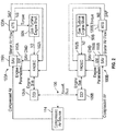
FIG. 2 is another schematic illustration of an aircraft engine starting system in accordance with an embodiment of the disclosure; -
FIG. 3 is a schematic illustration of a high spool gas path with a straddle-mounted spool in accordance with an embodiment of the disclosure; -
FIG. 4 is a schematic illustration of a high spool gas path with an overhung spool in accordance with an embodiment of the disclosure; -
FIG. 5 is a block diagram of a system for bowed rotor start mitigation in accordance with an embodiment of the disclosure; -
FIG. 6 is a block diagram of mode selection for single or multi-engine dry motoring control in accordance with an embodiment of the disclosure; and -
FIG. 7 is a flow chart illustrating a method in accordance with an embodiment of the disclosure. - Various embodiments of the present disclosure are related to a bowed rotor start mitigation system in a gas turbine engine. Embodiments can include using a starter air valve to control a rotor speed of a starting spool of a gas turbine engine to mitigate a bowed rotor condition using a dry motoring process. During dry motoring, the starter air valve can be actively adjusted to deliver air pressure (i.e., compressed air) from an air supply to an air turbine starter of an engine starting system that controls starting spool rotor speed. Dry motoring may be performed by running an engine starting system at a lower speed with a longer duration than typically used for engine starting while dynamically adjusting the starter air valve to maintain the rotor speed and/or follow a dry motoring profile. Some embodiments increase the rotor speed of the starting spool to approach a critical rotor speed gradually and as thermal distortion is decreased they then accelerate beyond the critical rotor speed to complete the engine starting process. The critical rotor speed refers to a major resonance speed where, if the temperatures are unhomogenized, the combination of a bowed rotor and similarly bowed casing and the resonance would lead to high amplitude oscillation in the rotor and high rubbing of blade tips on one side of the rotor, especially in the high pressure compressor if the rotor is straddle-mounted.
- A dry motoring profile for dry motoring can be selected based on various parameters, such as a modelled temperature value of the gas turbine engine used to estimate heat stored in the engine core when a start sequence is initiated and identify a risk of a bowed rotor. The modelled temperature value alone or in combination with other values (e.g., measured temperatures) can be used to calculate a bowed rotor risk parameter. For example, the modelled temperature can be adjusted relative to an ambient temperature when calculating the bowed rotor risk parameter. The bowed rotor risk parameter may be used to take a control action to mitigate the risk of starting the gas turbine engine with a bowed rotor. The control action can include dry motoring consistent with the dry motoring profile. In some embodiments, a targeted rotor speed profile of the dry motoring profile can be adjusted as dry motoring is performed.
- A full authority digital engine control (FADEC) system or other system may send a message to the cockpit to inform the crew of an extended time start time due to bowed rotor mitigation actions prior to completing an engine start sequence. If the engine is in a ground test or in a test stand, a message can be sent to the test stand or cockpit based on the control-calculated risk of a bowed rotor. A test stand crew can be alerted regarding a requirement to keep the starting spool of the engine to a speed below the known resonance speed of the rotor in order to homogenize the temperature of the rotor and the casings about the rotor which also are distorted by temperature non-uniformity.
- In order to further reduce total start time, embodiments enable dry motoring of multiple engines at the same time. Respective FADECs for each engine can provide parameters to one or more engine control interfaces including sensed temperatures and other values that may impact mode selection decisions for enabling single engine or multi-engine cranking for dry motoring. An engine control interface that receives the parameters can determine present conditions with respect to an operating envelope of a compressed air source and the starting system of each engine based on predetermined performance constraints, engine drag, and/or parasitic factors. Multi-engine cranking (e.g., dual engine cranking) can be commanded to perform dry motoring in multiple engines at the same time based on determining that each of the starting systems will receive a sufficient supply of compressed air for the engines to reach a targeted speed based on the present conditions. The engine control interface can continue monitoring performance of the engines during dry motoring and switch to single engine cranking upon determining that the engines are not reaching the targeted speed for a predetermined period of time.
- Referring now to
FIG. 1 , a schematic illustration of anaircraft 5 is depicted with a pair ofengine systems Engine systems gas turbine engines engine starting systems Engine systems gas turbine engines starting systems engine control interfaces digital communication bus 106. Theengine control interfaces FIG. 1 , in some embodiments theengine control interfaces FADECs engine control interfaces aircraft 5. - In an embodiment, the
FADECs engine control interfaces gas turbine engines FIG. 1 . The one or more processors can be any type of central processing unit (CPU), including a general purpose processor, a digital signal processor (DSP), a microcontroller, an application specific integrated circuit (ASIC), a field programmable gate array (FPGA), or the like. Also, in embodiments, the memory may include random access memory (RAM), read only memory (ROM), or other electronic, optical, magnetic, or any other computer readable medium onto which is stored data and control algorithms in a non-transitory form. - In the example of
FIG. 1 , an auxiliary power unit (APU) 113 andcompressor 115 provide acompressed air source 114 to driveair turbine starters engine starting systems 101A, 101 B. Compressed air from the compressedair source 114 is routed throughducts 117 andair starter valves air turbine starters ducts 117, such as amain shutoff valve 119 andengine shutoff valves more bleed valves 123 can be used to release compressed air from theducts 117. - In some cases, dry motoring can be performed simultaneously for
engine systems air source 114 is provided to bothair turbine starters engine systems starter air valve air turbine starter engine system FADECs engine system compressed air source 114. In embodiments,FADECs gas turbine engines FADECs gas turbine engines FADECs starter air valves gas turbine engines gas turbine engine - To further enhance control aspects, the
FADECs engine control interfaces starter air valves digital communication bus 106 to either or both of theengine control interfaces starter air valves air turbine starters engine control interfaces engine starting systems 101 A, 101 B. For example, at least one temperature ofgas turbine engines more engines - Although
FIG. 1 depicts one example configuration, it will be understood that embodiments as described herein can cover a wide range of configurations, such as a four engine system. Further, thecompressed air source 114 can include multiple sources other thanAPU 113 andcompressor 115, such as a ground cart or cross engine bleed air. - Turning now to
FIG. 2 , a schematic ofengine systems engine starting systems gas turbine engines FIG. 1 are depicted according to an embodiment. In the example ofFIG. 2 , thedigital communication bus 106 can include an aircraft, engine, and/or test stand communication bus to interface withFADECs engine control interfaces FADECs electromechanical devices starter air valves starter air valves APU 113 andcompressor 115 ofFIG. 1 ) as a starter air flow toair turbine starters air turbine starters turbine engine shafts gas turbine engines 10A, 10B. [0036] TheFADECs starter air valves FADECs starter air valves FADECs digital communication bus 106 toengine control interfaces engine system starter air valves - In some embodiments, the
starter air valves electromechanical devices FADECs electromechanical devices starter air valves turbine engine shafts electromechanical devices starter air valves starter air valves electromechanical devices starter air valves FADECs electromechanical devices starter air valves FADECs - In an alternate embodiment, rather than using
electromechanical devices starter air valves starter air valves FADECs starter air valves starter air valves starter air valves starter air valves starter air valves - In some embodiments, the
FADECs starter air valves FADECs starter air valves FADECs -
FIG. 3 and 4 depict two example engine configurations of thegas turbine engines FIG. 1 .FIG. 3 is an example of a straddle-mounted spool 32A as a starting spool configuration. This configuration places two bearingcompartments high pressure compressor 52A and at outside at least one of the turbine disks ofhigh pressure turbine 54A. In contrast with a straddle-mounted spool arrangement, other embodiments may be implemented using an over-hung mounted spool 32B as depicted inFIG. 4 as a starting spool configuration. In over-hung mounted spool 32B, abearing compartment 37B is located forward of the first turbine disk ofhigh pressure turbine 54B such that thehigh pressure turbine 54B is overhung, and it is physically located aft of its main supporting structure. The use of straddle-mounted spools has advantages and disadvantages in the design of a gas turbine, but one characteristic of the straddle-mounted design is that the span between the bearingcompartments compartments compartments high pressure turbine 54A orhigh pressure turbine 54B). As one example, a straddle-mounted engine starting spool, such as straddle-mounted spool 32A, with a roller bearing at bearingcompartment 39A located aft of thehigh pressure turbine 54A may be more vulnerable to bowed rotor problems since the Lsupport/Dhpt ranges from 1.9 to 5.6. -
FIGS. 3 and 4 also illustrate an air turbine starter 120 (e.g.,air turbine starter FIGS. 1 and2 ) interfacing throughgearbox 124 via atower shaft 55 with the straddle-mounted spool 32A proximatehigh compressor 52A and interfacing viatower shaft 55 with the overhung mounted spool 32B proximatehigh compressor 52B as part of a starting system. The straddle-mounted spool 32A and the over-hung mounted spool 32B are both examples of a starter spool having a gasturbine engine shaft 50 driven by theair turbine starter 120, such as gasturbine engine shafts air turbine starters FIG. 2 . -
FIG. 5 is a block diagram of asystem 200 for bowed rotor start mitigation that may control either of thestarter air valves FIGS. 1 and2 via control signals 210 in accordance with an embodiment. Thesystem 200 may also be referred to as a bowed rotor start mitigation system. In the example ofFIG. 5 , thesystem 200 includes anonboard model 202 operable to produce a compressor exit temperature T3 and a compressor inlet flow W25 of one of thegas turbine engines FIG. 1 for use by acore temperature model 204. Theonboard model 202 is configured to synthesize or predict major temperatures and pressures throughout one of thegas turbine engines FIG. 1 beyond those sensed by sensors positioned about thegas turbine engines onboard model 202 andcore temperature model 204 are examples of a first thermal model and a second thermal model that may be separately implemented or combined as part of a controller 102 (e.g.,FADECs FIG. 1 ). - Engine parameter synthesis is performed by the
onboard model 202, and the engine parameter synthesis may be performed using the technologies described in U.S. Patent Publication No.2011/0077783 , the entire contents of which are incorporated herein by reference thereto. Of the many parameters synthesized byonboard model 202 at least two are outputted to thecore temperature model 204, T3, which is the compressor exit gas temperature of eachgas turbine engine onboard model 202 and inputted into thecore temperature model 204 that synthesizes or provides a heat state (Tcore) of eachgas turbine engine controller 102. Accordingly, X is dependent upon the synthesized value of W25. In other words, W25 when compared to a lookup table of thecore temperature model 204 will determine a value X to be used in determining the heat state or Tcore of eachgas turbine engine - The heat state of each
engine core temperature model 204 as eachengine onboard model 202 and/or thecontroller 102 as eachengine - At engine shutdown, the current or most recently determined heat state of the engine or Tcore shutdown of an
engine DSU 104. TheDSU 104 retains data between shutdowns using non-volatile memory. Eachengine separate DSU 104. Time values and other parameters may be received ondigital communication bus 106. As long as electrical power is present for thecontroller 102 andDSU 104, additional values of temperature data may be monitored for comparison with modelled temperature data to validate one or more temperature models (e.g.,onboard model 202 and/or core temperature model 204) of eachgas turbine engine - During an engine start sequence or restart sequence, a bowed rotor start risk model 206 (also referred to as risk model 206) of the
controller 102 is provided with the data stored in theDSU 104, namely Tcore shutdown and the time of the engine shutdown tshutdown. In addition, the bowed rotorstart risk model 206 is also provided with the time of engine start tstart and the ambient temperature of the air provided to the inlet of eachengine - The bowed rotor
start risk model 206 maps core temperature model data with time data and ambient temperature data to establish a motoring time tmotoring as an estimated period of motoring to mitigate a bowed rotor of eachgas turbine engine start risk model 206. For example, a higher risk of a bowed rotor may result in a longer duration of dry motoring to reduce a temperature gradient prior to starting eachgas turbine engine FIG. 1 . In one embodiment, an engine start sequence may automatically include a modified start sequence; however, the duration of the modified start sequence prior to a normal start sequence will vary based upon the time period tmotoring that is calculated by the bowed rotorstart risk model 206. The motoring time tmotoring for predetermined target speed Ntarget of eachengine - Based upon these values (Tcore shutdown, tshutdown, tstart, T2 and/or Toil) the motoring time tmotoring at a predetermined target speed Ntarget for the modified start sequence of each
engine start risk model 206. Based upon the calculated time period tmotoring which is calculated as a time to run eachengine controller 102 can run through a modified start sequence upon a start command given to eachengine engines engines - In an alternate embodiment, the modified start sequence may only be run when the bowed rotor
start risk model 206 has determined that the motoring time tmotoring is greater than zero seconds upon receipt of a start command given to eachengine start risk model 206 has determined that tmotoring is not greater than zero seconds, a normal start sequence will be initiated upon receipt of a start command to eachengine - Accordingly and during an engine command start, the bowed rotor
start risk model 206 of thesystem 200 may be referenced wherein the bowed rotorstart risk model 206 correlates the elapsed time since the last engine shutdown time and the shutdown heat state of eachengine engine engine air turbine starter engine engine engine engine - The bowed rotor
start risk model 206 can output the motoring time tmotoring to amotoring controller 208. Themotoring controller 208 uses a dynamic control calculation in order to determine a required valve position of thestarter air valve air source 114 to theengine engine starter air valve starter air valve engine motoring controller 208 closes the loop for an engine motoring speed target Ntarget for the required amount of time based on the output of the bowed rotorstart risk model 206.Engine data 209 can also be transmitted ondigital communication bus 106 to theengine control interfaces system engine control interfaces engine data 209 can include a measured core engine temperature, an oil temperature, an ambient air temperature, an ambient pressure, a starting spool speed, and the like.Engine data 209 can also include a number of control parameters such as a dry motoring profile and/or adjustments to a dry motoring profile. The single/multi enginedry motoring mode 205 can be used to pause/delay dry motoring and/or change motoring target speed. Changes may include extending the motoring time requirements predicted by the bowed rotorstart risk model 206 and/or modifying a selection or applying a rescaling to a dry motoring profile determined by the bowed rotorstart risk model 206. - In one embodiment, the dynamic control of the valve position (e.g., open state of the valve (e.g., fully open, ½ open, ¼ open, etc.) in order to limit the motoring speed of the
engine electromechanical device starter air valves starter air valves valve angle 207 can be provided tomotoring control 208 based on valve angle feedback. A rotor speed N2 can be provided to themotoring controller 208 and amitigation monitor 214, where motoringcontroller 208 and amitigation monitor 214 may be part ofcontroller 102. - The
risk model 206 can determine a bowed rotor risk parameter that is based on the heat stored (Tcore) using a mapping function or lookup table. When not implemented as a fixed rotor speed, the bowed rotor risk parameter can have an associated dry motoring profile defining a target rotor speed profile over an anticipated amount of time for themotoring controller 208 to sendcontrol signals 210, such as valve control signals for controllingstarter air valves FIG. 3 . - The bowed rotor risk parameter may be quantified according to a profile curve selected from a family of curves that align with observed aircraft/engine conditions that impact turbine bore temperature and the resulting bowed rotor risk. In some embodiments, an anticipated amount of dry motoring time can be used to determine a target rotor speed profile in a dry motoring profile for the currently observed conditions. As one example, one or more baseline characteristic curves for the target rotor speed profile can be defined in tables or according to functions that may be rescaled to align with the observed conditions.
- In summary with reference to
FIG. 5 , as one example of anaircraft 5 that includes systems as described herein,onboard model 202 andcore temperature model 204 may run oncontroller 102 of theaircraft 5 to track heat stored (Tcore) in the turbine at the time of engine shutdown. Modelling of potential heat stored in the system may be performed as a turbine disk metal temperature model in thecore temperature model 204. When the aircraft lands, engines typically operate at idle for a cool down period of time, e.g., while taxiing to a final destination. When an engine shutdown is detected, model state data can be logged by theDSU 104 prior to depowering. When thecontroller 102 powers on at a later time and model state data can be retrieved from theDSU 104, and the bowed rotorstart risk model 206 can be updated to account for the elapsed time. When an engine start is requested, a bowed rotor risk can be assessed with respect to the bowed rotorstart risk model 206. Extended dry motoring can be performed during an engine start process until the bow risk has sufficiently diminished. The state of or changes to the single/multi enginedry motoring mode 205 can start/stop dry motoring and/or result in adjustments to motoring time and/or a dry motoring profile used to drive control signals 210. - In reference to
FIG. 5 , themitigation monitor 214 can operate in response to receiving acomplete indicator 212 to run a verification of the bowed rotor mitigation. The mitigation monitor 214 can providemitigation results 216 to themotoring controller 208 and may provideresult metrics 218 to other systems, such as a maintenance request or indicator. The mitigation monitor 214 may also run while dry motoring is active to determine whether adjustments to the dry motoring profile are needed. If themitigation monitor 214 determines that a bowed rotor condition still exists, themotoring controller 208 may restart dry motoring, or a maintenance request or indicator can be triggered along with providingresult metrics 218 for further analysis. Metrics of attempted bowed rotor mitigation can be recorded in theDSU 104 based on determining that the attempted bowed rotor mitigation was unsuccessful or incomplete. Mitigation results 216 and/or resultmetrics 218 may also be included in theengine data 209 sent toengine control interfaces FIG. 1 . -
FIG. 6 is a block diagram ofmode selection logic 250 for single or multi-engine dry motoring control in accordance with an embodiment. With respect to the description ofFIG. 6 ,engine system 100A is referred to as afirst engine system 100A, whileengine system 100B is referred to as asecond engine system 100B; however, it will be understood that the first/second designations can be reversed. Although inputs from only two engines are depicted in the example ofFIG. 6 , it will be understood that the design can scale to any number of engines (e.g., a four engine aircraft). Themode selection logic 250 may be part of either or both of theengine control interfaces FIG. 1 . - In the example of
FIG. 6 , themode selection logic 250 includes amode controller 252 and aspeed monitor 254. Themode controller 252 can receiveengine data 209 fromFADECs engine temperature value 256A and a secondengine temperature value 256B. Various parameters can be received or otherwise determined by theengine control interfaces turbine starter parameters 258, compressedair source parameters 260,engine drag 262,parasitic factors 264, andflight regime 266. The airturbine starter parameters 258 can include performance limitations of theair turbine starters air source parameters 260 can include performance limitations of thecompressed air source 114, such as output limits as a function of pressure and/or temperature. Theengine drag 262 may be determined as a function of oil temperature and/or ambient conditions for each of theengines parasitic factors 264 can be defined as correlations with respect to one or more of an ambient temperature, engine core temperature, and/or oil temperature. Theflight regime 266 can be used to determine when dry motoring should be enabled or inhibited. For instance, dry motoring can be inhibited when theaircraft 5 ofFIG. 1 is not on the ground. The various parameters available to themode controller 252 enable selection of an envelope map that corresponds with the current conditions to determine when the system is collectively capable of performing multi-engine dry motoring such that multiplegas turbine engines mode controller 252 are output as the single/multi enginedry motoring mode 205, for instance, toFADECs - The speed monitor 254 can also receive
engine data 209, which may include a first engine speed (e.g., N2 ofengine 10A) 270A, a first engine dry motoring enabledstatus 272A, a second engine speed (e.g., N2 ofengine 10B) 270B, and a second engine dry motoring enabledstatus 272B. When dry motoring is active inengines status speed monitor 254 can monitor the speed (e.g., first andsecond engine speed engines engine mode command 274 to themode controller 252 based on one or more of thegas turbine engines motoring threshold speed 276 for apredetermined time limit 278. In some embodiments, the drymotoring threshold speed 276 is dynamically adjusted to match a dry motoring profile. For example, the value used as the drymotoring threshold speed 276 can change over time as dry motoring continues such that the drymotoring threshold speed 276 need not be statically defined. In some embodiments, theengine data 209 includes a currently targeted speed for either or bothengines motoring threshold speed 276 are permitted. In other embodiments, theFADECs respective engine engine mode command 274, themode controller 252 can switch the single/multi enginedry motoring mode 205 from the multi-engine dry motoring mode to the single engine dry motoring mode and disable dry motoring in all but one of theengines -
FIG. 7 is a flow chart illustrating amethod 300 for multi-engine coordination during gas turbine engine motoring in accordance with an embodiment. Themethod 300 ofFIG. 7 is described in reference toFIGS. 1 to 6 and may be performed with an alternate order and include additional steps. Atblock 302, a controller (e.g., one of theengine control interfaces gas turbine engines engine data 209. The at least one temperature can be a measured core engine temperature (e.g., T3 or Tcore), an oil temperature (e.g., Toil), and/or an ambient temperature (e.g., Tamb or T2). Theengine data 209 can include a number of other parameters used to determine amotoring mode 205. - At
block 304, the controller (e.g., one of theengine control interfaces motoring mode 205 as a selection between a single engine dry motoring mode and a multi-engine dry motoring mode based on the at least one temperature of a plurality ofgas turbine engines motoring mode 205 can also be determined based on a plurality of performance parameters that are based on one or more of: an ambient condition, performance limitations of acompressed air source 114 and eachair turbine starter compressed air source 114, engine drag, and parasitic factors. Performance parameters can be determined based on one or more of: an ambient air temperature, an ambient pressure, and an oil temperature. Thecompressed air source 114 can be anauxiliary power unit 113 of theaircraft 5, a ground cart, or a cross engine bleed. - At
block 306, dry motoring is initiated based on themotoring mode 205. Initiation of dry motoring can be performed by communicating themotoring mode 205 to either or both of thegas turbine engines digital communication bus 106 toFADECs engine control interfaces motoring mode 205 is the single engine dry motoring mode, only a targeted controller (FADEC motoring mode 205 with eitherFADEC 102A orFADEC 102B. Similarly, if themotoring mode 205 is determined locally atFADEC 102A, the determination to perform single engine dry motoring forgas turbine engine 10A need not be shared withFADEC 102B. Dry motoring can be inhibited under certain conditions, such as when theaircraft 5 is not on the ground (e.g., a weight-on-wheels indication is set for dry motoring to be performed on eitherengine - At
block 308, a speed (e.g., N2 or NS) of each of thegas turbine engines block 310, a switch from the multi-engine dry motoring mode to the single engine dry motoring mode can be commanded based on one or more of thegas turbine engines motoring threshold speed 276 for apredetermined time limit 278. The drymotoring threshold speed 276 can be dynamically adjusted to match a dry motoring profile. - Accordingly and as mentioned above, it is desirable to detect, prevent and/or clear a "bowed rotor" condition in a gas turbine engine that may occur after the engine has been shut down. As described herein and in one non-limiting embodiment, the
FADECs engine control interfaces FADECs DSU 104 and/orengine control interfaces FADECs DSU 104 and/orengine control interfaces FADECs DSU 104 and/orengine control interfaces - While the present disclosure has been described in detail in connection with only a limited number of embodiments, it should be readily understood that the present disclosure is not limited to such disclosed embodiments. Rather, the present disclosure can be modified to incorporate any number of variations, alterations, substitutions or equivalent arrangements not heretofore described, but which are commensurate with the spirit and scope of the present disclosure. Additionally, while various embodiments of the present disclosure have been described, it is to be understood that aspects of the present disclosure may include only some of the described embodiments. Accordingly, the present disclosure is not to be seen as limited by the foregoing description, but is only limited by the scope of the appended claims.
Claims (15)
- A system for multi-engine coordination of gas turbine engine motoring in an aircraft, the system comprising:a controller operable to determine a motoring mode as a selection between a single engine dry motoring mode and a multi-engine dry motoring mode based on at least one temperature of a plurality of gas turbine engines and initiate dry motoring based on the motoring mode.
- The system as in claim 1, wherein the at least one temperature is a measured core engine temperature or an oil temperature.
- The system as in claim 1 or claim 2, wherein dry motoring is inhibited when the aircraft is not on the ground.
- The system as in any preceding claim, wherein the motoring mode is further determined based on a plurality of performance parameters that are based on one or more of: an ambient condition, performance limitations of a compressed air source and each air turbine starter driven by the compressed air source, engine drag, and parasitic factors.
- The system as in claim 4, wherein the performance parameters are determined based on one or more of: an ambient air temperature, an ambient pressure, and an oil temperature.
- The system as in any preceding claim, wherein the controller is further operable to monitor a speed of each of the gas turbine engines when dry motoring is active and switch from the multi-engine dry motoring mode to the single engine dry motoring mode based on one or more of the gas turbine engines failing to reach or maintain a dry motoring threshold speed for a predetermined time limit.
- The system as in claim 6, wherein the dry motoring threshold speed is dynamically adjusted to match a dry motoring profile.
- A system as claimed in any of claims 1, 3, 4, and 6, additionally comprising:a compressed air source operable to supply compressed air;a first engine system comprising a first gas turbine engine, a first air turbine starter, a first starter air valve, and a first controller operable to command the first starter air valve to control delivery of the compressed air to the first air turbine starter during motoring of the first gas turbine engine; anda second engine system comprising a second gas turbine engine, a second air turbine starter, a second starter air valve, and a second controller operable to command the second starter air valve to control delivery of the compressed air to the second air turbine starter during motoring of the second gas turbine engine;wherein said controller is provided as at least one engine control interface operable to determine said motoring mode as a selection between said single engine dry motoring mode and said multi-engine dry motoring mode based on at least one temperature of the first and second gas turbine engines and initiate dry motoring based on the motoring mode.
- The system as in claim 8, wherein the compressed air source is an auxiliary power unit of the aircraft, a ground cart, or a cross engine bleed.
- A method for multi-engine coordination during gas turbine engine motoring, the method comprising:receiving, by a controller, at least one temperature of a plurality of gas turbine engines;determining, by the controller, a motoring mode as a selection between a single engine dry motoring mode and a multi-engine dry motoring mode based on the at least one temperature of the plurality of gas turbine engines; andinitiating dry motoring based on the motoring mode.
- The method as in claim 10, further comprising inhibiting dry motoring when the aircraft is not on the ground.
- The method as in claim 10 or claim 11, wherein the motoring mode is further determined based on a plurality of performance parameters that are based on one or more of: an ambient condition, performance limitations of a compressed air source and each air turbine starter driven by the compressed air source, engine drag, and parasitic factors.
- The method as in claim 12, wherein the compressed air source is an auxiliary power unit of the aircraft, a ground cart, or a cross engine bleed.
- The method as in any of claims 10 to 13, further comprising:monitoring a speed of each of the gas turbine engines when dry motoring is active; andswitching from the multi-engine dry motoring mode to the single engine dry motoring mode based on one or more of the gas turbine engines failing to reach or maintain a dry motoring threshold speed for a predetermined time limit.
- The method as in claim 14, wherein the dry motoring threshold speed is dynamically adjusted to match a dry motoring profile.
Applications Claiming Priority (1)
| Application Number | Priority Date | Filing Date | Title |
|---|---|---|---|
| US201662365093P | 2016-07-21 | 2016-07-21 |
Publications (2)
| Publication Number | Publication Date |
|---|---|
| EP3273016A1 true EP3273016A1 (en) | 2018-01-24 |
| EP3273016B1 EP3273016B1 (en) | 2020-04-01 |
Family
ID=59383958
Family Applications (1)
| Application Number | Title | Priority Date | Filing Date |
|---|---|---|---|
| EP17181931.1A Active EP3273016B1 (en) | 2016-07-21 | 2017-07-18 | Multi-engine coordination during gas turbine engine motoring |
Country Status (2)
| Country | Link |
|---|---|
| US (2) | US11047257B2 (en) |
| EP (1) | EP3273016B1 (en) |
Cited By (1)
| Publication number | Priority date | Publication date | Assignee | Title |
|---|---|---|---|---|
| CN108549785A (en) * | 2018-05-03 | 2018-09-18 | 中国人民解放军国防科技大学 | Method for quickly predicting accurate trajectory of hypersonic aircraft based on three-dimensional flight profile |
Families Citing this family (25)
| Publication number | Priority date | Publication date | Assignee | Title |
|---|---|---|---|---|
| US10618666B2 (en) | 2016-07-21 | 2020-04-14 | United Technologies Corporation | Pre-start motoring synchronization for multiple engines |
| EP3273016B1 (en) | 2016-07-21 | 2020-04-01 | United Technologies Corporation | Multi-engine coordination during gas turbine engine motoring |
| US10384791B2 (en) | 2016-07-21 | 2019-08-20 | United Technologies Corporation | Cross engine coordination during gas turbine engine motoring |
| EP3273006B1 (en) | 2016-07-21 | 2019-07-03 | United Technologies Corporation | Alternating starter use during multi-engine motoring |
| US10221774B2 (en) | 2016-07-21 | 2019-03-05 | United Technologies Corporation | Speed control during motoring of a gas turbine engine |
| US10787968B2 (en) | 2016-09-30 | 2020-09-29 | Raytheon Technologies Corporation | Gas turbine engine motoring with starter air valve manual override |
| US10443543B2 (en) | 2016-11-04 | 2019-10-15 | United Technologies Corporation | High compressor build clearance reduction |
| US10934885B2 (en) * | 2016-11-07 | 2021-03-02 | Raytheon Technologies Corporation | System and method for controlling dual starter air valve |
| US10823079B2 (en) | 2016-11-29 | 2020-11-03 | Raytheon Technologies Corporation | Metered orifice for motoring of a gas turbine engine |
| US11199137B2 (en) | 2018-09-26 | 2021-12-14 | Raytheon Technologies Corporation | Gas turbine engine system cooldown |
| US11306654B2 (en) | 2018-12-19 | 2022-04-19 | Raytheon Technologies Corporation | Gas turbine engine system wear reduction |
| US11199139B2 (en) | 2018-12-19 | 2021-12-14 | Raytheon Technologies Corporation | Gas turbine engine system bowed rotor start mitigation and wear reduction |
| US11162382B2 (en) | 2019-02-21 | 2021-11-02 | General Electric Company | Method and system for engine operation |
| US11274599B2 (en) | 2019-03-27 | 2022-03-15 | Pratt & Whitney Canada Corp. | Air system switching system to allow aero-engines to operate in standby mode |
| EP3726480B1 (en) | 2019-04-17 | 2024-09-25 | RTX Corporation | Remote updates of a gas turbine engine |
| US10977877B2 (en) | 2019-04-17 | 2021-04-13 | Raytheon Technologies Corporation | Engine gateway with engine data storage |
| US11208916B2 (en) * | 2019-04-17 | 2021-12-28 | Raytheon Technologies Corporation | Self-healing remote dynamic data recording |
| EP3726325B1 (en) | 2019-04-17 | 2022-08-24 | Raytheon Technologies Corporation | Gas turbine engine with dynamic data recording |
| US11492132B2 (en) | 2019-04-17 | 2022-11-08 | Raytheon Technologies Corporation | Gas turbine engine configuration data synchronization with a ground-based system |
| EP3726324B1 (en) | 2019-04-17 | 2023-03-01 | Raytheon Technologies Corporation | Gas turbine engine communication gateway with internal sensors |
| EP3726323B1 (en) | 2019-04-17 | 2023-03-08 | Raytheon Technologies Corporation | Gas turbine engine communication gateway with integral antennas |
| US11913643B2 (en) | 2019-04-17 | 2024-02-27 | Rtx Corporation | Engine wireless sensor system with energy harvesting |
| US11859563B2 (en) * | 2019-05-31 | 2024-01-02 | Pratt & Whitney Canada Corp. | Air system of multi-engine aircraft |
| US11274611B2 (en) | 2019-05-31 | 2022-03-15 | Pratt & Whitney Canada Corp. | Control logic for gas turbine engine fuel economy |
| US11668250B2 (en) | 2019-11-11 | 2023-06-06 | Pratt & Whitney Canada Corp. | System and method for engine operation in a multi-engine aircraft |
Citations (4)
| Publication number | Priority date | Publication date | Assignee | Title |
|---|---|---|---|---|
| US20110077783A1 (en) | 2008-11-03 | 2011-03-31 | United Technologies Corporation | System and method for design and control of engineering systems utilizing component-level dynamic mathematical model |
| EP2305986A2 (en) * | 2009-10-05 | 2011-04-06 | General Electric Company | Methods and systems for mitigating distortion of gas turbine shaft |
| US20140283527A1 (en) * | 2013-03-25 | 2014-09-25 | Honeywell International Inc. | Multi-engine performance margin synchronization adaptive control system and method |
| US20140373553A1 (en) * | 2013-06-25 | 2014-12-25 | Airbus Operations (Sas) | Method and system for starting up an aircraft turbomachine |
Family Cites Families (143)
| Publication number | Priority date | Publication date | Assignee | Title |
|---|---|---|---|---|
| US1951875A (en) | 1932-08-06 | 1934-03-20 | Cutler Hammer Inc | Power transmission mechanism |
| US2617253A (en) | 1950-09-23 | 1952-11-11 | Gen Electric | Safety control system for cooling a gas turbine power plant on shutdown |
| GB717183A (en) | 1952-03-14 | 1954-10-20 | Power Jets Res & Dev Ltd | Improvements in or relating to control arrangements for rotating machinery |
| US2840987A (en) | 1953-03-23 | 1958-07-01 | Gen Electric | Improved method and arrangement for starting reaction type propulsion units using anauxiliary reaction type propulsion unit |
| NL113963C (en) | 1959-05-15 | |||
| US2962597A (en) | 1959-06-09 | 1960-11-29 | Westinghouse Electric Corp | Power plant apparatus |
| US3098626A (en) | 1960-11-21 | 1963-07-23 | Lockheed Aircraft Corp | System for starting gas turbine power plants |
| US3151452A (en) | 1962-10-22 | 1964-10-06 | Bendix Corp | Electro-mechanical control for air breathing starter |
| GB1186375A (en) | 1966-07-13 | 1970-04-02 | Plessey Co Ltd | Improvements in or relating to Engine-Starter Systems including a Self-Contained Air-Compressor feeding a Pneumatic Starter Motor |
| CA932397A (en) | 1970-10-20 | 1973-08-21 | Westinghouse Electric Corporation | System and method for accelerating and sequencing industrial gas turbine apparatus and gas turbine electric power plants preferably with a digital computer control system |
| US3898439A (en) | 1970-10-20 | 1975-08-05 | Westinghouse Electric Corp | System for operating industrial gas turbine apparatus and gas turbine electric power plants preferably with a digital computer control system |
| DE2110747B2 (en) | 1971-03-06 | 1975-06-26 | Siemens Ag, 1000 Berlin Und 8000 Muenchen | Starting device for a generator coupled to a turbine |
| US3812378A (en) | 1972-03-09 | 1974-05-21 | Bendix Corp | Aircraft starter control system |
| US3793905A (en) | 1972-08-14 | 1974-02-26 | Twin Disc Inc | Gas turbine starting and auxiliary turning mechanism |
| US3951008A (en) | 1975-01-08 | 1976-04-20 | Twin Disc, Incorporated | Power transmitting mechanism for starting a high inertia load and having retarder means for auxiliary starting motor |
| US4044550A (en) | 1975-09-10 | 1977-08-30 | The Boeing Company | Turbine wheel containment shroud for a pneumatically powered turbine engine starter motor |
| JPS5274737A (en) | 1975-12-19 | 1977-06-23 | Hitachi Ltd | Operation stopper of hydraulical machinery |
| US4069424A (en) | 1976-05-10 | 1978-01-17 | Turbodyne Corporation (Gas Turbine Div.) | Shaft turning parking bus for multiple unit installations utilizing a single motorized generator control system |
| US4380146A (en) | 1977-01-12 | 1983-04-19 | Westinghouse Electric Corp. | System and method for accelerating and sequencing industrial gas turbine apparatus and gas turbine electric power plants preferably with a digital computer control system |
| GB2117842A (en) | 1982-03-25 | 1983-10-19 | Rolls Royce | Means for equalising the temperatures within a gas turbine engine |
| US4627234A (en) | 1983-06-15 | 1986-12-09 | Sundstrand Corporation | Gas turbine engine/load compressor power plants |
| JPS60256643A (en) | 1984-05-31 | 1985-12-18 | Moritomo Ando | Speed reducer |
| US4598551A (en) | 1985-10-25 | 1986-07-08 | General Electric Company | Apparatus and method for controlling steam turbine operating conditions during starting and loading |
| US4669893A (en) | 1986-02-18 | 1987-06-02 | United Technologies Corporation | Annular oil damper arrangement |
| US4702273A (en) | 1986-03-07 | 1987-10-27 | Parker Hannifin Corporation | Electrically controlled starter air valve |
| US4854120A (en) | 1986-09-26 | 1989-08-08 | Cef Industries, Inc. | Performance envelope extension method for a gas turbine engine |
| US4733529A (en) | 1986-09-26 | 1988-03-29 | Cef Industries, Inc. | Performance envelope extension device for a gas turbine engine |
| US4979362A (en) | 1989-05-17 | 1990-12-25 | Sundstrand Corporation | Aircraft engine starting and emergency power generating system |
| US4979365A (en) | 1989-09-25 | 1990-12-25 | Actronics Incorporated | Electrothermally operated actuator |
| US5103629A (en) | 1989-11-20 | 1992-04-14 | Westinghouse Electric Corp. | Gas turbine control system having optimized ignition air flow control |
| US5184458A (en) | 1989-11-21 | 1993-02-09 | Lampe Steven W | Power unit fuel pressurization system |
| US5201798A (en) | 1990-09-24 | 1993-04-13 | Allied-Signal Inc. | Multifunction integrated power unit and power transfer apparatus therefor |
| US5174109A (en) | 1990-10-25 | 1992-12-29 | Sundstrand Corporation | Clutch to disconnect loads during turbine start-up |
| US5123239A (en) | 1991-02-14 | 1992-06-23 | Sundstrand Corporation | Method of starting a gas turbine engine |
| US5127220A (en) | 1991-02-28 | 1992-07-07 | Allied-Signal Inc. | Method for accelerating a gas turbine engine |
| US5349814A (en) | 1993-02-03 | 1994-09-27 | General Electric Company | Air-start assembly and method |
| US5463865A (en) | 1993-09-30 | 1995-11-07 | General Electric Company | Starter air valve position pressure transducer |
| DE19727296A1 (en) | 1997-06-27 | 1999-01-07 | Mtu Muenchen Gmbh | Device for the emergency shutdown of a gas turbine |
| WO2000011324A1 (en) | 1998-08-18 | 2000-03-02 | Siemens Aktiengesellschaft | Turbine housing |
| US6318958B1 (en) | 1998-08-21 | 2001-11-20 | Alliedsignal, Inc. | Air turbine starter with seal assembly |
| US6146090A (en) | 1998-12-22 | 2000-11-14 | General Electric Co. | Cooling/heating augmentation during turbine startup/shutdown using a seal positioned by thermal response of turbine parts and consequent relative movement thereof |
| US6190127B1 (en) | 1998-12-22 | 2001-02-20 | General Electric Co. | Tuning thermal mismatch between turbine rotor parts with a thermal medium |
| US6168377B1 (en) | 1999-01-27 | 2001-01-02 | General Electric Co. | Method and apparatus for eliminating thermal bowing of steam turbine rotors |
| GB2348466B (en) | 1999-03-27 | 2003-07-09 | Rolls Royce Plc | A gas turbine engine and a rotor for a gas turbine engine |
| US6305156B1 (en) | 1999-09-03 | 2001-10-23 | Alliedsignal Inc. | Integrated bleed air and engine starting system |
| JP3593488B2 (en) | 2000-02-25 | 2004-11-24 | 株式会社日立製作所 | gas turbine |
| US7190705B2 (en) | 2000-05-23 | 2007-03-13 | Imra America. Inc. | Pulsed laser sources |
| US6498978B2 (en) | 2001-05-18 | 2002-12-24 | General Electric Company | System and method for monitoring thermal state to normalize engine trending data |
| WO2002095768A1 (en) | 2001-05-25 | 2002-11-28 | Pebble Bed Modular Reactor (Proprietary) Limited | A brayton cycle nuclear power plant and a method of starting the brayton cycle |
| JP2002371806A (en) | 2001-06-18 | 2002-12-26 | Mitsubishi Heavy Ind Ltd | Turbine device |
| US6684898B2 (en) | 2001-09-27 | 2004-02-03 | Honeywell International Inc. | Dual actuator air turbine starter valve |
| US6558118B1 (en) | 2001-11-01 | 2003-05-06 | General Electric Company | Bucket dovetail bridge member and method for eliminating thermal bowing of steam turbine rotors |
| US6517314B1 (en) | 2001-11-05 | 2003-02-11 | General Electric Company | Method and apparatus for eliminating thermal bowing and axial thrust loads of steam turbine rotors |
| US6694746B2 (en) | 2002-02-06 | 2004-02-24 | Honeywell International, Inc. | Micro volume actuator for an air turbine starter |
| US6681579B2 (en) | 2002-02-07 | 2004-01-27 | Honeywell International, Inc. | Air turbine starter with fluid flow control |
| US6762512B2 (en) | 2002-05-10 | 2004-07-13 | Siemens Westinghourse Power Corporation | Methods for starting a combustion turbine and combustion turbine generator configured to implement same methods |
| US6935836B2 (en) | 2002-06-05 | 2005-08-30 | Allison Advanced Development Company | Compressor casing with passive tip clearance control and endwall ovalization control |
| US7133801B2 (en) | 2002-06-07 | 2006-11-07 | Exxon Mobil Research And Engineering Company | System and methodology for vibration analysis and condition monitoring |
| JP3949014B2 (en) | 2002-06-28 | 2007-07-25 | 株式会社荏原製作所 | Gas turbine equipment |
| GB0218060D0 (en) | 2002-08-03 | 2002-09-11 | Alstom Switzerland Ltd | Sealing arrangements |
| EP1512907A1 (en) | 2003-09-03 | 2005-03-09 | Siemens Aktiengesellschaft | Method for starting a once-through steam generator and the once-through steam generator for carrying out said method |
| US7409319B2 (en) | 2003-11-24 | 2008-08-05 | General Electric Company | Method and apparatus for detecting rub in a turbomachine |
| US20100132365A1 (en) | 2004-04-20 | 2010-06-03 | Gustavo Francisco Labala | Start-Up Control For a Compact Lightweight Turbine |
| CH697258B1 (en) | 2004-06-22 | 2008-07-31 | Alstom Technology Ltd | A method of operating a gas turbine. |
| GB0416344D0 (en) | 2004-07-22 | 2004-08-25 | Rolls Royce Plc | Generator assembly |
| US7104072B2 (en) | 2004-08-16 | 2006-09-12 | Hamilton Sundstrand Corporation | Combined power main engine start system |
| US7513119B2 (en) | 2005-02-03 | 2009-04-07 | The Boeing Company | Systems and methods for starting aircraft engines |
| US7555905B2 (en) | 2006-03-28 | 2009-07-07 | United Technologies Corporation | Self-actuating bleed valve for gas turbine engine |
| US7909566B1 (en) | 2006-04-20 | 2011-03-22 | Florida Turbine Technologies, Inc. | Rotor thrust balance activated tip clearance control system |
| US9121309B2 (en) | 2006-06-10 | 2015-09-01 | Mtu Aero Engines Gmbh | Gas turbine and method of operating a gas turbine |
| US7770400B2 (en) | 2006-12-26 | 2010-08-10 | General Electric Company | Non-linear fuel transfers for gas turbines |
| US7972105B2 (en) | 2007-05-10 | 2011-07-05 | General Electric Company | Turbine anti-rotating stall schedule |
| US7742881B2 (en) | 2007-08-02 | 2010-06-22 | General Electric Company | System and method for detection of rotor eccentricity baseline shift |
| US20120240591A1 (en) | 2007-12-10 | 2012-09-27 | General Electric Company | Method for shutting down a generator to prepare the generator for restart |
| US8291715B2 (en) | 2008-06-11 | 2012-10-23 | Honeywell International Inc. | Bi-modal turbine assembly and starter / drive turbine system employing the same |
| FR2933131B1 (en) | 2008-06-25 | 2015-06-26 | Snecma | SUPPORT FOR FASTENING A RING SURROUNDING THE MOBILE BLADES OF A TURBINE |
| KR101164046B1 (en) | 2008-06-30 | 2012-07-20 | 미츠비시 쥬고교 가부시키가이샤 | Method and system for calculating core shift of rotating body |
| US20100085676A1 (en) | 2008-10-03 | 2010-04-08 | Honeywell International Inc. | Nested pulse width modulation control |
| ES2382721T3 (en) | 2008-10-20 | 2012-06-12 | Mactaggart Scott (Holdings) Ltd. | Device and method to rotate a tree |
| US8167567B2 (en) | 2008-12-17 | 2012-05-01 | United Technologies Corporation | Gas turbine engine airfoil |
| US8245517B2 (en) | 2009-05-19 | 2012-08-21 | Hamilton Sundstrand Corporation | Gas turbine starting with stepping speed control |
| US20100326085A1 (en) | 2009-06-25 | 2010-12-30 | Veilleux Leo J | Lightweight start system for a gas turbine engine |
| US8306791B2 (en) | 2009-12-21 | 2012-11-06 | United Technologies Corporation | Method and system for modeling the performance of a gas turbine engine |
| US20110146276A1 (en) | 2009-12-23 | 2011-06-23 | General Electric Company | Method of starting a steam turbine |
| GB201003084D0 (en) | 2010-02-24 | 2010-04-14 | Rolls Royce Plc | An aerofoil |
| US9086018B2 (en) | 2010-04-23 | 2015-07-21 | Hamilton Sundstrand Corporation | Starting a gas turbine engine to maintain a dwelling speed after light-off |
| US20110296843A1 (en) | 2010-06-04 | 2011-12-08 | Lawson Jr T Towles | Positive displacement power extraction compensation device |
| US8770913B1 (en) | 2010-06-17 | 2014-07-08 | Florida Turbine Technologies, Inc. | Apparatus and process for rotor creep monitoring |
| US8667803B2 (en) | 2010-09-22 | 2014-03-11 | Hamilton Sundstrand Corporation | Turbine starter valve |
| US8744634B2 (en) * | 2010-11-19 | 2014-06-03 | General Electric Company | Safety instrumented system (SIS) for a turbine system |
| US9845734B2 (en) | 2011-04-20 | 2017-12-19 | Honeywell International Inc. | Air turbine start system with monopole starter air valve position |
| US9151182B2 (en) | 2011-04-22 | 2015-10-06 | General Electric Company | System and method for removing heat from a turbomachine |
| FR2976315B1 (en) | 2011-06-09 | 2015-01-23 | Airbus Operations Sas | METHOD AND DEVICE FOR AIDING THE MONITORING OF AN AIRCRAFT TURBOMACHINE |
| FR2977915B1 (en) | 2011-07-12 | 2018-11-16 | Safran Helicopter Engines | METHOD FOR STARTING A TURBOMACHINE REDUCING THERMAL BALANCE |
| US20130031912A1 (en) | 2011-08-01 | 2013-02-07 | Hamilton Sundstrand Corporation | Gas turbine start architecture |
| CH705551A1 (en) | 2011-09-19 | 2013-03-28 | Alstom Technology Ltd | The self-adjusting device for controlling the clearance, especially in the radial direction between rotating and stationary components of a thermally loaded turbomachinery. |
| US20130091850A1 (en) | 2011-10-13 | 2013-04-18 | Hamilton Sundstrand Corporation | Method and system for reducing hot soakback |
| ITFI20110247A1 (en) | 2011-11-14 | 2013-05-15 | Nuovo Pignone Spa | "DEVICE AND METHOD FOR SLOW TURNING OF AN AERODERIVATIVE GAS TURBINE" |
| WO2013075720A2 (en) | 2011-11-21 | 2013-05-30 | Vestas Wind Systems A/S | A shutdown controller for a wind turbine and a method of shutting down a wind turbine |
| US8776530B2 (en) | 2011-11-23 | 2014-07-15 | General Electric Company | Gas turbine engine lockout reduction |
| US9470231B2 (en) | 2012-01-06 | 2016-10-18 | Borgwarner Inc. | Electrically assisted turbocharger |
| JP5984447B2 (en) | 2012-03-26 | 2016-09-06 | 三菱重工業株式会社 | Method for preventing deformation of casing of gas turbine, purge device for executing the method, and gas turbine equipped with the device |
| FR2990004B1 (en) | 2012-04-27 | 2014-04-18 | Turbomeca | METHOD AND SYSTEM FOR EMERGENCY STARTING ENERGY GENERATING ARCHITECTURE |
| US9103284B2 (en) | 2012-05-31 | 2015-08-11 | General Electric Company | Utilization of fuel gas for purging a dormant fuel gas circuit |
| EP2757230A1 (en) | 2013-01-16 | 2014-07-23 | Alstom Technology Ltd | Method for barring a rotor of a turbomachine and barring apparatus for conducting such method |
| US9759068B2 (en) | 2013-02-28 | 2017-09-12 | General Electric Company | System and method for controlling a wind turbine based on identified surface conditions of the rotor blades |
| US9279339B2 (en) | 2013-03-13 | 2016-03-08 | Siemens Aktiengesellschaft | Turbine engine temperature control system with heating element for a gas turbine engine |
| JP6604939B2 (en) | 2013-03-15 | 2019-11-13 | ユナイテッド テクノロジーズ コーポレイション | Control system, control method and gas turbine engine |
| US20140301820A1 (en) | 2013-04-03 | 2014-10-09 | Uwe Lohse | Turbine engine shutdown temperature control system with nozzle injection for a gas turbine engine |
| US9605597B2 (en) | 2013-06-13 | 2017-03-28 | Solar Turbines Incorporated | Variable frequency drive power ride thru |
| FR3007459B1 (en) | 2013-06-19 | 2016-10-14 | Airbus Operations Sas | SYSTEM AND METHOD FOR ROTATING A ROTARY MEMBER OF A MECHANICAL DEVICE, IN PARTICULAR A TURBOMACHINE. |
| US10309317B2 (en) | 2013-06-21 | 2019-06-04 | Hamilton Sundstrand Corporation | Air turbine starter pressure monitor system |
| US9181866B2 (en) | 2013-06-21 | 2015-11-10 | Caterpillar Inc. | Energy recovery and cooling system for hybrid machine powertrain |
| FR3007460B1 (en) | 2013-06-25 | 2015-07-17 | Airbus Operations Sas | METHOD AND SYSTEM FOR STARTING AN AIRCRAFT TURBOMACHINE BY REAL TIME REGULATION OF AIR FLOW. |
| GB2516048A (en) | 2013-07-09 | 2015-01-14 | Rolls Royce Plc | Tip clearance control method |
| US20160160875A1 (en) | 2013-08-26 | 2016-06-09 | United Technologies Corporation | Gas turbine engine with fan clearance control |
| GB2518893B (en) | 2013-10-07 | 2018-11-21 | Ge Aviat Systems Ltd | Method for predicting an auxiliary power unit fault |
| US9835135B2 (en) | 2013-10-31 | 2017-12-05 | General Electric Company | System and method for controlling a wind turbine |
| JP6295062B2 (en) | 2013-11-07 | 2018-03-14 | 三菱日立パワーシステムズ株式会社 | Steam turbine plant start-up control device |
| US9863400B2 (en) | 2013-12-11 | 2018-01-09 | General Electric Company | System and method for controlling a wind turbine system |
| US9567906B2 (en) | 2013-12-13 | 2017-02-14 | Honeywell International Inc. | Systems and methods for controlling aircraft main engine speeds by adjusting compressed air flow from an APU |
| FR3017159B1 (en) | 2014-01-31 | 2016-03-04 | Snecma | AIR SUPPLYING AN AIR CONDITIONING CIRCUIT OF A CABIN OF AN AIRCRAFT FROM ITS TURBOPROPULSOR |
| FR3019224B1 (en) | 2014-03-27 | 2016-03-18 | Turbomeca | METHOD FOR ASSISTING A MULTI-ENGINE HELICOPTER SLEEPING TURBOMOTEUR AND ARCHITECTURE OF A PROPELLANT HELICOPTER SYSTEM COMPRISING AT LEAST ONE TURBOMOTEUR WHICH CAN BE ON SLEEP |
| US9732762B2 (en) | 2014-08-27 | 2017-08-15 | Pratt & Whitney Canada Corp. | Compressor airfoil |
| US10502139B2 (en) | 2015-01-28 | 2019-12-10 | General Electric Company | Method of starting a gas turbine engine including a cooling phase |
| FR3037617B1 (en) | 2015-06-17 | 2019-06-28 | Safran Aircraft Engines | TURBOMACHINE DISCHARGE VEIN CONDUIT COMPRISING VARIABLE SECTION VBV GRID AND PASSIVE ACTUATION |
| US10443507B2 (en) | 2016-02-12 | 2019-10-15 | United Technologies Corporation | Gas turbine engine bowed rotor avoidance system |
| US10508567B2 (en) | 2016-02-12 | 2019-12-17 | United Technologies Corporation | Auxiliary drive bowed rotor prevention system for a gas turbine engine through an engine accessory |
| US10125691B2 (en) | 2016-02-12 | 2018-11-13 | United Technologies Corporation | Bowed rotor start using a variable position starter valve |
| US20170234235A1 (en) | 2016-02-12 | 2017-08-17 | Hamilton Sundstrand Corporation | Electro-pneumatic gas turbine engine motoring system for bowed rotor engine starts |
| US10436064B2 (en) | 2016-02-12 | 2019-10-08 | United Technologies Corporation | Bowed rotor start response damping system |
| FR3047771A1 (en) * | 2016-02-16 | 2017-08-18 | Airbus Operations Sas | SYSTEM AND METHOD FOR STARTING THE ENGINES OF A BIMOTING AIRCRAFT |
| US10724443B2 (en) * | 2016-05-24 | 2020-07-28 | General Electric Company | Turbine engine and method of operating |
| US10221774B2 (en) | 2016-07-21 | 2019-03-05 | United Technologies Corporation | Speed control during motoring of a gas turbine engine |
| US10384791B2 (en) | 2016-07-21 | 2019-08-20 | United Technologies Corporation | Cross engine coordination during gas turbine engine motoring |
| US10618666B2 (en) | 2016-07-21 | 2020-04-14 | United Technologies Corporation | Pre-start motoring synchronization for multiple engines |
| EP3273016B1 (en) | 2016-07-21 | 2020-04-01 | United Technologies Corporation | Multi-engine coordination during gas turbine engine motoring |
| US20180023479A1 (en) | 2016-07-21 | 2018-01-25 | United Technologies Corporation | Air supply control during motoring of a gas turbine engine |
| EP3273006B1 (en) | 2016-07-21 | 2019-07-03 | United Technologies Corporation | Alternating starter use during multi-engine motoring |
| US10428744B2 (en) | 2016-08-15 | 2019-10-01 | Hamilton Sundstrand Corporation | Fuel pump health detection |
| US10787968B2 (en) | 2016-09-30 | 2020-09-29 | Raytheon Technologies Corporation | Gas turbine engine motoring with starter air valve manual override |
| US10443543B2 (en) | 2016-11-04 | 2019-10-15 | United Technologies Corporation | High compressor build clearance reduction |
| US10823079B2 (en) | 2016-11-29 | 2020-11-03 | Raytheon Technologies Corporation | Metered orifice for motoring of a gas turbine engine |
-
2017
- 2017-07-18 EP EP17181931.1A patent/EP3273016B1/en active Active
- 2017-07-21 US US15/656,444 patent/US11047257B2/en active Active
-
2021
- 2021-06-28 US US17/359,894 patent/US11674411B2/en active Active
Patent Citations (4)
| Publication number | Priority date | Publication date | Assignee | Title |
|---|---|---|---|---|
| US20110077783A1 (en) | 2008-11-03 | 2011-03-31 | United Technologies Corporation | System and method for design and control of engineering systems utilizing component-level dynamic mathematical model |
| EP2305986A2 (en) * | 2009-10-05 | 2011-04-06 | General Electric Company | Methods and systems for mitigating distortion of gas turbine shaft |
| US20140283527A1 (en) * | 2013-03-25 | 2014-09-25 | Honeywell International Inc. | Multi-engine performance margin synchronization adaptive control system and method |
| US20140373553A1 (en) * | 2013-06-25 | 2014-12-25 | Airbus Operations (Sas) | Method and system for starting up an aircraft turbomachine |
Cited By (2)
| Publication number | Priority date | Publication date | Assignee | Title |
|---|---|---|---|---|
| CN108549785A (en) * | 2018-05-03 | 2018-09-18 | 中国人民解放军国防科技大学 | Method for quickly predicting accurate trajectory of hypersonic aircraft based on three-dimensional flight profile |
| CN108549785B (en) * | 2018-05-03 | 2021-09-24 | 中国人民解放军国防科技大学 | A Rapid Prediction Method for Accurate Ballistics of Hypersonic Vehicles Based on 3D Flight Profile |
Also Published As
| Publication number | Publication date |
|---|---|
| US20210324758A1 (en) | 2021-10-21 |
| EP3273016B1 (en) | 2020-04-01 |
| US11047257B2 (en) | 2021-06-29 |
| US11674411B2 (en) | 2023-06-13 |
| US20180023413A1 (en) | 2018-01-25 |
Similar Documents
| Publication | Publication Date | Title |
|---|---|---|
| US11674411B2 (en) | Multi-engine coordination during gas turbine engine motoring | |
| US11807378B2 (en) | Alternating starter use during multi-engine motoring | |
| US11840968B2 (en) | Motoring synchronization for multiple engines | |
| EP3273036B1 (en) | Speed control during motoring of a gas turbine engine | |
| EP3296522B1 (en) | Cross engine coordination during gas turbine engine motoring | |
| EP3273007B1 (en) | Air supply control during motoring of a gas turbine engine | |
| US11274604B2 (en) | Bowed rotor start mitigation in a gas turbine engine using aircraft-derived parameters | |
| EP3333377B1 (en) | Metered orifice for motoring of a gas turbine engine | |
| US10443543B2 (en) | High compressor build clearance reduction | |
| EP3205859B1 (en) | Gas turbine engine bowed rotor avoidance system | |
| EP3205858B1 (en) | Modified start sequence of a gas turbine engine | |
| US10787968B2 (en) | Gas turbine engine motoring with starter air valve manual override |
Legal Events
| Date | Code | Title | Description |
|---|---|---|---|
| PUAI | Public reference made under article 153(3) epc to a published international application that has entered the european phase |
Free format text: ORIGINAL CODE: 0009012 |
|
| STAA | Information on the status of an ep patent application or granted ep patent |
Free format text: STATUS: THE APPLICATION HAS BEEN PUBLISHED |
|
| AK | Designated contracting states |
Kind code of ref document: A1 Designated state(s): AL AT BE BG CH CY CZ DE DK EE ES FI FR GB GR HR HU IE IS IT LI LT LU LV MC MK MT NL NO PL PT RO RS SE SI SK SM TR |
|
| AX | Request for extension of the european patent |
Extension state: BA ME |
|
| STAA | Information on the status of an ep patent application or granted ep patent |
Free format text: STATUS: REQUEST FOR EXAMINATION WAS MADE |
|
| 17P | Request for examination filed |
Effective date: 20180724 |
|
| RBV | Designated contracting states (corrected) |
Designated state(s): AL AT BE BG CH CY CZ DE DK EE ES FI FR GB GR HR HU IE IS IT LI LT LU LV MC MK MT NL NO PL PT RO RS SE SI SK SM TR |
|
| GRAP | Despatch of communication of intention to grant a patent |
Free format text: ORIGINAL CODE: EPIDOSNIGR1 |
|
| STAA | Information on the status of an ep patent application or granted ep patent |
Free format text: STATUS: GRANT OF PATENT IS INTENDED |
|
| RIC1 | Information provided on ipc code assigned before grant |
Ipc: F01D 19/02 20060101ALI20190918BHEP Ipc: F01D 25/34 20060101AFI20190918BHEP Ipc: F02C 9/00 20060101ALI20190918BHEP |
|
| INTG | Intention to grant announced |
Effective date: 20191009 |
|
| GRAS | Grant fee paid |
Free format text: ORIGINAL CODE: EPIDOSNIGR3 |
|
| GRAA | (expected) grant |
Free format text: ORIGINAL CODE: 0009210 |
|
| STAA | Information on the status of an ep patent application or granted ep patent |
Free format text: STATUS: THE PATENT HAS BEEN GRANTED |
|
| AK | Designated contracting states |
Kind code of ref document: B1 Designated state(s): AL AT BE BG CH CY CZ DE DK EE ES FI FR GB GR HR HU IE IS IT LI LT LU LV MC MK MT NL NO PL PT RO RS SE SI SK SM TR |
|
| REG | Reference to a national code |
Ref country code: GB Ref legal event code: FG4D |
|
| REG | Reference to a national code |
Ref country code: CH Ref legal event code: EP Ref country code: AT Ref legal event code: REF Ref document number: 1251599 Country of ref document: AT Kind code of ref document: T Effective date: 20200415 |
|
| REG | Reference to a national code |
Ref country code: DE Ref legal event code: R096 Ref document number: 602017013861 Country of ref document: DE |
|
| REG | Reference to a national code |
Ref country code: IE Ref legal event code: FG4D |
|
| PG25 | Lapsed in a contracting state [announced via postgrant information from national office to epo] |
Ref country code: BG Free format text: LAPSE BECAUSE OF FAILURE TO SUBMIT A TRANSLATION OF THE DESCRIPTION OR TO PAY THE FEE WITHIN THE PRESCRIBED TIME-LIMIT Effective date: 20200701 |
|
| REG | Reference to a national code |
Ref country code: NL Ref legal event code: MP Effective date: 20200401 |
|
| REG | Reference to a national code |
Ref country code: LT Ref legal event code: MG4D |
|
| PG25 | Lapsed in a contracting state [announced via postgrant information from national office to epo] |
Ref country code: CZ Free format text: LAPSE BECAUSE OF FAILURE TO SUBMIT A TRANSLATION OF THE DESCRIPTION OR TO PAY THE FEE WITHIN THE PRESCRIBED TIME-LIMIT Effective date: 20200401 Ref country code: IS Free format text: LAPSE BECAUSE OF FAILURE TO SUBMIT A TRANSLATION OF THE DESCRIPTION OR TO PAY THE FEE WITHIN THE PRESCRIBED TIME-LIMIT Effective date: 20200801 Ref country code: FI Free format text: LAPSE BECAUSE OF FAILURE TO SUBMIT A TRANSLATION OF THE DESCRIPTION OR TO PAY THE FEE WITHIN THE PRESCRIBED TIME-LIMIT Effective date: 20200401 Ref country code: LT Free format text: LAPSE BECAUSE OF FAILURE TO SUBMIT A TRANSLATION OF THE DESCRIPTION OR TO PAY THE FEE WITHIN THE PRESCRIBED TIME-LIMIT Effective date: 20200401 Ref country code: PT Free format text: LAPSE BECAUSE OF FAILURE TO SUBMIT A TRANSLATION OF THE DESCRIPTION OR TO PAY THE FEE WITHIN THE PRESCRIBED TIME-LIMIT Effective date: 20200817 Ref country code: GR Free format text: LAPSE BECAUSE OF FAILURE TO SUBMIT A TRANSLATION OF THE DESCRIPTION OR TO PAY THE FEE WITHIN THE PRESCRIBED TIME-LIMIT Effective date: 20200702 Ref country code: SE Free format text: LAPSE BECAUSE OF FAILURE TO SUBMIT A TRANSLATION OF THE DESCRIPTION OR TO PAY THE FEE WITHIN THE PRESCRIBED TIME-LIMIT Effective date: 20200401 Ref country code: NO Free format text: LAPSE BECAUSE OF FAILURE TO SUBMIT A TRANSLATION OF THE DESCRIPTION OR TO PAY THE FEE WITHIN THE PRESCRIBED TIME-LIMIT Effective date: 20200701 Ref country code: NL Free format text: LAPSE BECAUSE OF FAILURE TO SUBMIT A TRANSLATION OF THE DESCRIPTION OR TO PAY THE FEE WITHIN THE PRESCRIBED TIME-LIMIT Effective date: 20200401 |
|
| REG | Reference to a national code |
Ref country code: AT Ref legal event code: MK05 Ref document number: 1251599 Country of ref document: AT Kind code of ref document: T Effective date: 20200401 |
|
| PG25 | Lapsed in a contracting state [announced via postgrant information from national office to epo] |
Ref country code: RS Free format text: LAPSE BECAUSE OF FAILURE TO SUBMIT A TRANSLATION OF THE DESCRIPTION OR TO PAY THE FEE WITHIN THE PRESCRIBED TIME-LIMIT Effective date: 20200401 Ref country code: HR Free format text: LAPSE BECAUSE OF FAILURE TO SUBMIT A TRANSLATION OF THE DESCRIPTION OR TO PAY THE FEE WITHIN THE PRESCRIBED TIME-LIMIT Effective date: 20200401 Ref country code: LV Free format text: LAPSE BECAUSE OF FAILURE TO SUBMIT A TRANSLATION OF THE DESCRIPTION OR TO PAY THE FEE WITHIN THE PRESCRIBED TIME-LIMIT Effective date: 20200401 |
|
| PG25 | Lapsed in a contracting state [announced via postgrant information from national office to epo] |
Ref country code: AL Free format text: LAPSE BECAUSE OF FAILURE TO SUBMIT A TRANSLATION OF THE DESCRIPTION OR TO PAY THE FEE WITHIN THE PRESCRIBED TIME-LIMIT Effective date: 20200401 |
|
| REG | Reference to a national code |
Ref country code: DE Ref legal event code: R097 Ref document number: 602017013861 Country of ref document: DE |
|
| PG25 | Lapsed in a contracting state [announced via postgrant information from national office to epo] |
Ref country code: EE Free format text: LAPSE BECAUSE OF FAILURE TO SUBMIT A TRANSLATION OF THE DESCRIPTION OR TO PAY THE FEE WITHIN THE PRESCRIBED TIME-LIMIT Effective date: 20200401 Ref country code: DK Free format text: LAPSE BECAUSE OF FAILURE TO SUBMIT A TRANSLATION OF THE DESCRIPTION OR TO PAY THE FEE WITHIN THE PRESCRIBED TIME-LIMIT Effective date: 20200401 Ref country code: AT Free format text: LAPSE BECAUSE OF FAILURE TO SUBMIT A TRANSLATION OF THE DESCRIPTION OR TO PAY THE FEE WITHIN THE PRESCRIBED TIME-LIMIT Effective date: 20200401 Ref country code: IT Free format text: LAPSE BECAUSE OF FAILURE TO SUBMIT A TRANSLATION OF THE DESCRIPTION OR TO PAY THE FEE WITHIN THE PRESCRIBED TIME-LIMIT Effective date: 20200401 Ref country code: SM Free format text: LAPSE BECAUSE OF FAILURE TO SUBMIT A TRANSLATION OF THE DESCRIPTION OR TO PAY THE FEE WITHIN THE PRESCRIBED TIME-LIMIT Effective date: 20200401 Ref country code: RO Free format text: LAPSE BECAUSE OF FAILURE TO SUBMIT A TRANSLATION OF THE DESCRIPTION OR TO PAY THE FEE WITHIN THE PRESCRIBED TIME-LIMIT Effective date: 20200401 Ref country code: ES Free format text: LAPSE BECAUSE OF FAILURE TO SUBMIT A TRANSLATION OF THE DESCRIPTION OR TO PAY THE FEE WITHIN THE PRESCRIBED TIME-LIMIT Effective date: 20200401 |
|
| PLBE | No opposition filed within time limit |
Free format text: ORIGINAL CODE: 0009261 |
|
| STAA | Information on the status of an ep patent application or granted ep patent |
Free format text: STATUS: NO OPPOSITION FILED WITHIN TIME LIMIT |
|
| PG25 | Lapsed in a contracting state [announced via postgrant information from national office to epo] |
Ref country code: PL Free format text: LAPSE BECAUSE OF FAILURE TO SUBMIT A TRANSLATION OF THE DESCRIPTION OR TO PAY THE FEE WITHIN THE PRESCRIBED TIME-LIMIT Effective date: 20200401 Ref country code: MC Free format text: LAPSE BECAUSE OF FAILURE TO SUBMIT A TRANSLATION OF THE DESCRIPTION OR TO PAY THE FEE WITHIN THE PRESCRIBED TIME-LIMIT Effective date: 20200401 Ref country code: SK Free format text: LAPSE BECAUSE OF FAILURE TO SUBMIT A TRANSLATION OF THE DESCRIPTION OR TO PAY THE FEE WITHIN THE PRESCRIBED TIME-LIMIT Effective date: 20200401 |
|
| REG | Reference to a national code |
Ref country code: CH Ref legal event code: PL |
|
| 26N | No opposition filed |
Effective date: 20210112 |
|
| REG | Reference to a national code |
Ref country code: BE Ref legal event code: MM Effective date: 20200731 |
|
| PG25 | Lapsed in a contracting state [announced via postgrant information from national office to epo] |
Ref country code: LU Free format text: LAPSE BECAUSE OF NON-PAYMENT OF DUE FEES Effective date: 20200718 Ref country code: LI Free format text: LAPSE BECAUSE OF NON-PAYMENT OF DUE FEES Effective date: 20200731 Ref country code: CH Free format text: LAPSE BECAUSE OF NON-PAYMENT OF DUE FEES Effective date: 20200731 |
|
| PG25 | Lapsed in a contracting state [announced via postgrant information from national office to epo] |
Ref country code: BE Free format text: LAPSE BECAUSE OF NON-PAYMENT OF DUE FEES Effective date: 20200731 Ref country code: SI Free format text: LAPSE BECAUSE OF FAILURE TO SUBMIT A TRANSLATION OF THE DESCRIPTION OR TO PAY THE FEE WITHIN THE PRESCRIBED TIME-LIMIT Effective date: 20200401 |
|
| PG25 | Lapsed in a contracting state [announced via postgrant information from national office to epo] |
Ref country code: IE Free format text: LAPSE BECAUSE OF NON-PAYMENT OF DUE FEES Effective date: 20200718 |
|
| PG25 | Lapsed in a contracting state [announced via postgrant information from national office to epo] |
Ref country code: TR Free format text: LAPSE BECAUSE OF FAILURE TO SUBMIT A TRANSLATION OF THE DESCRIPTION OR TO PAY THE FEE WITHIN THE PRESCRIBED TIME-LIMIT Effective date: 20200401 Ref country code: MT Free format text: LAPSE BECAUSE OF FAILURE TO SUBMIT A TRANSLATION OF THE DESCRIPTION OR TO PAY THE FEE WITHIN THE PRESCRIBED TIME-LIMIT Effective date: 20200401 Ref country code: CY Free format text: LAPSE BECAUSE OF FAILURE TO SUBMIT A TRANSLATION OF THE DESCRIPTION OR TO PAY THE FEE WITHIN THE PRESCRIBED TIME-LIMIT Effective date: 20200401 |
|
| PG25 | Lapsed in a contracting state [announced via postgrant information from national office to epo] |
Ref country code: MK Free format text: LAPSE BECAUSE OF FAILURE TO SUBMIT A TRANSLATION OF THE DESCRIPTION OR TO PAY THE FEE WITHIN THE PRESCRIBED TIME-LIMIT Effective date: 20200401 |
|
| REG | Reference to a national code |
Ref country code: DE Ref legal event code: R081 Ref document number: 602017013861 Country of ref document: DE Owner name: RAYTHEON TECHNOLOGIES CORPORATION (N.D.GES.D.S, US Free format text: FORMER OWNER: UNITED TECHNOLOGIES CORPORATION, FARMINGTON, CONN., US Ref country code: DE Ref legal event code: R081 Ref document number: 602017013861 Country of ref document: DE Owner name: RTX CORPORATION (N.D.GES.D. STAATES DELAWARE),, US Free format text: FORMER OWNER: UNITED TECHNOLOGIES CORPORATION, FARMINGTON, CONN., US |
|
| P01 | Opt-out of the competence of the unified patent court (upc) registered |
Effective date: 20230520 |
|
| PGFP | Annual fee paid to national office [announced via postgrant information from national office to epo] |
Ref country code: GB Payment date: 20250619 Year of fee payment: 9 |
|
| PGFP | Annual fee paid to national office [announced via postgrant information from national office to epo] |
Ref country code: FR Payment date: 20250620 Year of fee payment: 9 |
|
| PGFP | Annual fee paid to national office [announced via postgrant information from national office to epo] |
Ref country code: DE Payment date: 20250620 Year of fee payment: 9 |
|
| REG | Reference to a national code |
Ref country code: DE Ref legal event code: R081 Ref document number: 602017013861 Country of ref document: DE Owner name: RTX CORPORATION (N.D.GES.D. STAATES DELAWARE),, US Free format text: FORMER OWNER: RAYTHEON TECHNOLOGIES CORPORATION (N.D.GES.D.STAATES DELAWARE), ARLINGTON, VA, US |