EP3272628A2 - Vehicle jack positioning device and methods of making and using the same - Google Patents
Vehicle jack positioning device and methods of making and using the same Download PDFInfo
- Publication number
- EP3272628A2 EP3272628A2 EP17180911.4A EP17180911A EP3272628A2 EP 3272628 A2 EP3272628 A2 EP 3272628A2 EP 17180911 A EP17180911 A EP 17180911A EP 3272628 A2 EP3272628 A2 EP 3272628A2
- Authority
- EP
- European Patent Office
- Prior art keywords
- jack
- vehicle
- channel
- face
- support member
- Prior art date
- Legal status (The legal status is an assumption and is not a legal conclusion. Google has not performed a legal analysis and makes no representation as to the accuracy of the status listed.)
- Withdrawn
Links
- 238000000034 method Methods 0.000 title claims description 17
- 238000000576 coating method Methods 0.000 claims description 7
- 239000011248 coating agent Substances 0.000 claims description 6
- 239000000463 material Substances 0.000 claims description 6
- 229910052751 metal Inorganic materials 0.000 claims description 4
- 239000002184 metal Substances 0.000 claims description 4
- 238000003466 welding Methods 0.000 claims description 4
- 239000000853 adhesive Substances 0.000 claims description 3
- 230000001070 adhesive effect Effects 0.000 claims description 3
- 238000007689 inspection Methods 0.000 abstract description 2
- 230000006378 damage Effects 0.000 description 3
- 238000001746 injection moulding Methods 0.000 description 2
- 238000000465 moulding Methods 0.000 description 2
- 238000005192 partition Methods 0.000 description 2
- 238000011179 visual inspection Methods 0.000 description 2
- RTAQQCXQSZGOHL-UHFFFAOYSA-N Titanium Chemical compound [Ti] RTAQQCXQSZGOHL-UHFFFAOYSA-N 0.000 description 1
- 208000027418 Wounds and injury Diseases 0.000 description 1
- 238000004026 adhesive bonding Methods 0.000 description 1
- 229910045601 alloy Inorganic materials 0.000 description 1
- 239000000956 alloy Substances 0.000 description 1
- 229910052782 aluminium Inorganic materials 0.000 description 1
- XAGFODPZIPBFFR-UHFFFAOYSA-N aluminium Chemical compound [Al] XAGFODPZIPBFFR-UHFFFAOYSA-N 0.000 description 1
- 230000009286 beneficial effect Effects 0.000 description 1
- 238000000071 blow moulding Methods 0.000 description 1
- 238000005266 casting Methods 0.000 description 1
- 239000003086 colorant Substances 0.000 description 1
- 238000010276 construction Methods 0.000 description 1
- 230000008878 coupling Effects 0.000 description 1
- 238000010168 coupling process Methods 0.000 description 1
- 238000005859 coupling reaction Methods 0.000 description 1
- 230000000694 effects Effects 0.000 description 1
- 230000003028 elevating effect Effects 0.000 description 1
- 238000001125 extrusion Methods 0.000 description 1
- 208000014674 injury Diseases 0.000 description 1
- 238000005304 joining Methods 0.000 description 1
- 238000012423 maintenance Methods 0.000 description 1
- 238000004519 manufacturing process Methods 0.000 description 1
- 230000008569 process Effects 0.000 description 1
- 238000010107 reaction injection moulding Methods 0.000 description 1
- 230000003014 reinforcing effect Effects 0.000 description 1
- 230000008439 repair process Effects 0.000 description 1
- 230000000717 retained effect Effects 0.000 description 1
- 239000010936 titanium Substances 0.000 description 1
- 229910052719 titanium Inorganic materials 0.000 description 1
Images


Classifications
-
- B—PERFORMING OPERATIONS; TRANSPORTING
- B60—VEHICLES IN GENERAL
- B60S—SERVICING, CLEANING, REPAIRING, SUPPORTING, LIFTING, OR MANOEUVRING OF VEHICLES, NOT OTHERWISE PROVIDED FOR
- B60S11/00—Vehicle modifications for receiving separate lifting, supporting, or manoeuvring devices
-
- B—PERFORMING OPERATIONS; TRANSPORTING
- B23—MACHINE TOOLS; METAL-WORKING NOT OTHERWISE PROVIDED FOR
- B23P—METAL-WORKING NOT OTHERWISE PROVIDED FOR; COMBINED OPERATIONS; UNIVERSAL MACHINE TOOLS
- B23P6/00—Restoring or reconditioning objects
-
- B—PERFORMING OPERATIONS; TRANSPORTING
- B62—LAND VEHICLES FOR TRAVELLING OTHERWISE THAN ON RAILS
- B62D—MOTOR VEHICLES; TRAILERS
- B62D25/00—Superstructure or monocoque structure sub-units; Parts or details thereof not otherwise provided for
- B62D25/20—Floors or bottom sub-units
- B62D25/2081—Jack receiving devices
-
- B—PERFORMING OPERATIONS; TRANSPORTING
- B66—HOISTING; LIFTING; HAULING
- B66F—HOISTING, LIFTING, HAULING OR PUSHING, NOT OTHERWISE PROVIDED FOR, e.g. DEVICES WHICH APPLY A LIFTING OR PUSHING FORCE DIRECTLY TO THE SURFACE OF A LOAD
- B66F13/00—Common constructional features or accessories
-
- B—PERFORMING OPERATIONS; TRANSPORTING
- B66—HOISTING; LIFTING; HAULING
- B66F—HOISTING, LIFTING, HAULING OR PUSHING, NOT OTHERWISE PROVIDED FOR, e.g. DEVICES WHICH APPLY A LIFTING OR PUSHING FORCE DIRECTLY TO THE SURFACE OF A LOAD
- B66F3/00—Devices, e.g. jacks, adapted for uninterrupted lifting of loads
- B66F3/08—Devices, e.g. jacks, adapted for uninterrupted lifting of loads screw operated
- B66F3/12—Devices, e.g. jacks, adapted for uninterrupted lifting of loads screw operated comprising toggle levers
-
- B—PERFORMING OPERATIONS; TRANSPORTING
- B66—HOISTING; LIFTING; HAULING
- B66F—HOISTING, LIFTING, HAULING OR PUSHING, NOT OTHERWISE PROVIDED FOR, e.g. DEVICES WHICH APPLY A LIFTING OR PUSHING FORCE DIRECTLY TO THE SURFACE OF A LOAD
- B66F3/00—Devices, e.g. jacks, adapted for uninterrupted lifting of loads
- B66F3/24—Devices, e.g. jacks, adapted for uninterrupted lifting of loads fluid-pressure operated
- B66F3/25—Constructional features
- B66F3/36—Load-engaging elements
Definitions
- This presently disclosed subject matter is directed to a device for properly positioning a vehicle jack, and to methods of making and using the same.
- Vehicle jacks are frequently used to elevate a vehicle to facilitate maintenance and repair activities, such as during the changing of a tire. Virtually all vehicles require the vehicle jack to be positioned relative to and make contact with the vehicle in an optimal spot to allow efficient and safe operation of the jack.
- the jack point is generally located on the underside of the vehicle frame near the vehicle wheels, the proper position for the jack is often difficult to determine by feel or visual inspection. Often jack operators are guided by only their visual inspection of the vehicle frame, resulting in an imprecise estimate as to the proper jack point. Further, determination of the proper jack point is particularly difficult when jack operation is conducted in the dark, during inclement weather, and/or by an operator not accustomed to frequent use of a vehicle jack.
- the presently disclosed subject matter is directed to a method comprising engaging a channel defined in a top facing surface of a jack point extension device with a jack point of a vehicle; providing translation forces to a bottom surface of the jack point extension device with a jack by engaging a receiving element of the jack with a protrusion extending from the bottom surface and actuating the jack; and after translation of the vehicle, disengaging the jack from the protrusion while the channel of the jack point extension remains engaged with the jack point of the vehicle.
- the protrusion keeps the jack from sliding out of position.
- the channel is attached to the vehicle jack point using an adhesive, welding, mechanical closures, or combinations thereof.
- the channel extends from a front face of the device to a rear face of the device.
- the vehicle jack point is a vehicle pinch weld.
- the device channel and the vehicle jack point have about the same cross-sectional size, shape, or both.
- the receiving element comprises a nonslip or friction-resistant coating.
- the receiving element is approximately centrally located on the bottom face.
- the device is constructed from metal, polymeric material, or combinations thereof.
- the jack comprises a receiving element sized and shaped to engage with the protrusion, and two contact surfaces that contact the bottom surface of the device when the receiving element is engaged with the protrusion.
- the presently disclosed subject matter is directed to a device for attaching to a vehicle, the device comprising: a top face and a bottom face; a front face and a rear face; a channel disposed on the top face, wherein the channel is sized and shaped to house a vehicle jack point; and a support member disposed on the bottom face and extending downward therefrom, wherein the support member is sized and shaped to be housed within the receiving element of a vehicle jack.
- the top face and the bottom face are disposed parallel to each other, the front face and the rear face are disposed parallel to each other, or both.
- the channel extends on the top face from the front face to the rear face.
- the channel and the vehicle jack point have about the same cross-sectional size and shape.
- the support member comprises a nonslip or friction-resistant coating.
- bottom refers to a location on the presently disclosed device along the lower surface thereof, as shown in the orientation depicted in the Figures.
- the bottom face of the disclosed device is the face that includes the support member.
- the top face is positioned opposite to the bottom face.
- channel refers to an unfilled space suitable for housing a vehicle jack point.
- Coupled refers to the joining of two elements, either permanently or temporarily.
- the term "jack point" refers to the proper location on a vehicle where a jack is to make contact with the vehicle during operation of the jack.
- the term jack point is the optimal location on the vehicle frame where the jack acts during operation and raising of the vehicle.
- the jack point can be a pinch weld.
- the term "receiving element” refers to an element of a car jack that houses a support member as set forth herein.
- the receiving element can comprise a lock-fit arrangement with the support member, clamps, or other components that releasably grasp the support member, and/or a housing into which the support member is coupled for a desired amount of time.
- support member refers to an element through which a vehicle jack supports a vehicle.
- a support member of the presently disclosed subject matter can be coupled to a vehicle jack to raise and/or lower the vehicle.
- top refers to a location on the presently disclosed device along the upper surface thereof as seen in the orientation shown in the Figures.
- the top face of the disclosed device is the face that includes the channel.
- the top face is positioned opposite to the bottom face.
- vehicle refers to any motorized or other structure likely to travel, such as cars, vans, buses, trucks, motorcycles, off-road recreational vehicles, tractors, and the like.
- vehicle jack refers to any type of apparatus used to raise, lower, level, or support a vehicle.
- vehicle jack can include (but is not limited to) a crank jack, electric jack, hydraulic jack, trailer tongue jack, scissors-type jack, screw-type jack, and the like.
- FIG. 1 illustrates a jack positioning device in accordance with some embodiments of the presently disclosed subject matter.
- device 5 includes top face 10 (which functions as the vehicle-engaging face of the device), bottom face 15 (which functions as the jack-engaging face of the device), front face 20 , rear face 25 , and sides 30.
- device 5 is disposed in a generally upright position, with bottom face 15 facing downwards and top face 10 facing upwards.
- top face 10 and bottom face 15 are disposed about parallel to each other.
- front face 20 and rear face 25 are disposed about parallel to each other.
- the front face is disposed about perpendicularly to the top face and/or bottom face.
- the rear face is disposed about perpendicularly to the top face and/or bottom face.
- Top face 10 comprises channel 35 comprising inner surface 40 , top channel opening 45 , and bottom partition 50 , opposite to the top channel opening.
- the channel can span the distance between the front and rear faces, as shown in Figure 1 .
- the channel is of a uniform width.
- the width of channel 35 can taper to accommodate a variety of jack points of varying widths.
- Channel 35 is configured to receive a vehicle jack point.
- the vehicle jack point comprises a width and depth that is approximately the same width and depth as channel 35 , such that the jack point is capable of fitting closely into the channel.
- channel 35 can be configured in any desirable shape to cooperate with a vehicle jack point, including (but not limited to) a circular, rectangular, square, oblong, etc. cross-section.
- channel 35 and the vehicle jack point have the same cross-sectional size and/or shape.
- channel 35 is sized and shaped to be affixed to a vehicle jack point (i.e., the jack point fits into the channel and is permanently maintained in position in some embodiments).
- the channel extends substantially perpendicularly to the front and/or rear faces of the device. It should be appreciated that channel 35 can be configured to allow device 5 to be adapted for use on all types of vehicles, without limitation.
- Bottom face 15 of device 5 comprises a protrusion (support member 55 ) that projects away from bottom face 15 (i.e., outward from the device) and is adapted to cooperate with a vehicle jack.
- the support member is approximately centrally located on bottom face 15 , i.e., about equidistant from sides 30 .
- support member 55 extends from front face 20 to rear face 25 on bottom face 15 .
- the support member is positioned perpendicularly to the bottom face of the device. The support member cooperates with the receiving element of a vehicle jack. It should be appreciated that support member 55 provides the support structure for the vehicle jack. Particularly, the support member is at least partially or fully contained within a vehicle jack receiving element.
- the jack comprises a receiving element sized and shaped to engage with the support member, and two contact surfaces that contact the bottom surface of the device when the receiving element is engaged with the protrusion.
- support member 55 can include a nonslip or friction-resistant coating applied to the surface to maintain engagement with the vehicle jack. Such coatings are well known to those of ordinary skill in the art.
- Support member 55 can be configured in any desirable shape to cooperate with the receiving element of a vehicle jack, including (but not limited to) a rectangular, square, oblong, etc. cross-section. In some embodiments, support member 55 and the receiving element have about the same cross-sectional size and/or shape. Thus, support member 55 can be sized and shaped to be coupled with the receiving element of a vehicle jack. It should be appreciated that support member 55 can be configured to allow device 5 to be adapted for use with all types of vehicle jacks, without limitation.
- Sides 30 of device 5 can be shaped in any way desired.
- the device can include sloped sides spanning the distance between top face 10 and bottom face 15 , as illustrated in Figure 1 .
- sides 30 can comprise an angle of no more than (or no less than) about 5, 10, 15, 20, 25, 30, 35, 40, 45, 50, 55, 60, 65, 70, 75, 80, 85, 90, 95, 100, 105, 110, 115, 120, 125, 130, 135, 140, or 145 degrees, relative to top face 10 and/or bottom face 15 .
- sides 30 are not required to be angled and can be configured in any shape known in the art.
- the shape of device 5 is not limited and can be configured in any form desired, so long as the device includes channel 35 and support member 55 .
- the size of device 5 is not limited.
- the device can have dimensions of about 5 cm x 5 cm x 5 cm (or about 2 inches x 2 inches x 2 inches) (length x width x height).
- device 5 is mated with vehicle 65 such that channel 35 and vehicle jack point 60 are disposed in an abutting and aligned relationship relative to one another (i.e., channel 35 is sized and shaped to house jack point 60 , which can be a protruded element sized and shaped to fit into the channel).
- channel 35 is sized and shaped to house jack point 60 , which can be a protruded element sized and shaped to fit into the channel.
- device 5 and the vehicle are aligned such that jack point 60 is positioned above channel 35 .
- the device can then be elevated until the jack point is housed within channel 35 .
- channel 35 has a diameter that is slightly greater than the outer diameter of jack point 60 such that the jack point freely but closely fits into the channel.
- device 5 can be permanently attached to the vehicle jack point using any method known in the art, including (but not limited to) adhesive bonding, welding, mechanical fasteners (i.e., bolting, riveting, clamping, etc.), engaging by fit and shape, and the like to ensure that the channel remains permanently positioned on vehicle jack point 60 .
- adhesive bonding i.e., bolting, riveting, clamping, etc.
- it can be applied along channel interior 40 and/or channel bottom partition 50 to engage vehicle jack point 60 and secure the device to the vehicle.
- Device 5 can therefore be utilized in a manner to assure the safe and positive gripping of the vehicle by the jack during the elevating process, thus eliminating the hazards associated with improper positioning of the jack.
- jack 70 can be positioned below bottom face 15 of device 5 to be in proper position to raise and lower the vehicle. Specifically, a selected vehicle jack 70 is placed underneath vehicle 65 , such that jack receiving element 75 is positioned at a location below and aligned with support member 55 , as illustrated in Figure 3a . The operator will then raise the jack until receiving element 75 engages support member 55 .
- the support member is sized and shaped to cooperate with the receiving element of the jack, such that the support member is capable of fitting closely into the receiving element.
- support member 55 and receiving element 75 have about the same cross-sectional size and/or shape.
- the support member is sized and shaped to be housed within the receiving element of the jack. It should be appreciated that the support member is releasably housed in the receiving element of the jack such that a user can easily couple and uncouple the support member on demand.
- support member 55 is received and retained within receiving element 75 of jack 70 and is held in position for a desired amount of time (i.e., while the vehicle is raised, until the vehicle has been lowered, etc.).
- the disclosed device prevents damage to vehicles caused by supporting the vehicles in non-approved jacking locations.
- the jack can be detached from support member 55 via uncoupling the support member and the receiving element, as shown in Figure 3c .
- device 5 ensures proper positioning of a vehicle jack underneath a vehicle and ensures effective engagement with the appropriate part of the framework of the vehicle. Further, the device provides, among others, the advantages of increasing the degree of stability of the jack, reinforcing the jack at mechanically critical parts of the vehicle, and making it easier for the user to initially install the jack under the vehicle body.
- Device 5 can be constructed from any material known in the art to be rugged and durable, thereby ensuring many years of intended usage.
- the material used to construct device 5 should be capable of withstanding the force applied upon contact of the jack. Therefore, in some embodiments, device 5 can be constructed from metal, polymeric material, combinations thereof, and the like, as would be known in the art.
- the device can be constructed from a lightweight but high-strength metal, such as (but not limited to) aluminum, titanium, and/or alloys or combinations thereof.
- the device can include bright colors and/or glow-in-the-dark areas (such as on and/or around support member 55 or bottom face 15 ) to assist users in correctly positioning the jack.
- Device 5 can be constructed using any of a wide variety of techniques, including (but not limited to) welding, injection molding, gas-assisted injection molding, extrusion, reaction-injection molding, slush molding, pour molding, blow molding, and/or casting using any of the materials described above.
- the presently disclosed device is therefore relatively inexpensive to manufacture due to its simplicity of construction. It should be appreciated that device 5 can be manufactured and installed as part of the original equipment of the vehicle, or can be readily attached to the vehicle later as an accessory item with a minimum of time and labor involved.
Landscapes
- Engineering & Computer Science (AREA)
- Mechanical Engineering (AREA)
- Life Sciences & Earth Sciences (AREA)
- Geology (AREA)
- Structural Engineering (AREA)
- Chemical & Material Sciences (AREA)
- Combustion & Propulsion (AREA)
- Transportation (AREA)
- Vehicle Cleaning, Maintenance, Repair, Refitting, And Outriggers (AREA)
Abstract
Description
- This presently disclosed subject matter is directed to a device for properly positioning a vehicle jack, and to methods of making and using the same.
- Vehicle jacks are frequently used to elevate a vehicle to facilitate maintenance and repair activities, such as during the changing of a tire. Virtually all vehicles require the vehicle jack to be positioned relative to and make contact with the vehicle in an optimal spot to allow efficient and safe operation of the jack. However, because the jack point is generally located on the underside of the vehicle frame near the vehicle wheels, the proper position for the jack is often difficult to determine by feel or visual inspection. Often jack operators are guided by only their visual inspection of the vehicle frame, resulting in an imprecise estimate as to the proper jack point. Further, determination of the proper jack point is particularly difficult when jack operation is conducted in the dark, during inclement weather, and/or by an operator not accustomed to frequent use of a vehicle jack. Operation of a jack in an improper position can damage the vehicle and/or cause the vehicle to slip off the jack and expose the operator to physical injury. Accordingly, it would be beneficial to provide a device that can assist the jack operator in determining the proper placement of the vehicle jack relative to the vehicle.
- In some embodiments, the presently disclosed subject matter is directed to a method comprising engaging a channel defined in a top facing surface of a jack point extension device with a jack point of a vehicle; providing translation forces to a bottom surface of the jack point extension device with a jack by engaging a receiving element of the jack with a protrusion extending from the bottom surface and actuating the jack; and after translation of the vehicle, disengaging the jack from the protrusion while the channel of the jack point extension remains engaged with the jack point of the vehicle.
- In some embodiments, the protrusion keeps the jack from sliding out of position. In some embodiments, the channel is attached to the vehicle jack point using an adhesive, welding, mechanical closures, or combinations thereof. In some embodiments, the channel extends from a front face of the device to a rear face of the device. In some embodiments, the vehicle jack point is a vehicle pinch weld. In some embodiments, the device channel and the vehicle jack point have about the same cross-sectional size, shape, or both. In some embodiments, the receiving element comprises a nonslip or friction-resistant coating. In some embodiments, the receiving element is approximately centrally located on the bottom face. In some embodiments, the device is constructed from metal, polymeric material, or combinations thereof. In some embodiments, the jack comprises a receiving element sized and shaped to engage with the protrusion, and two contact surfaces that contact the bottom surface of the device when the receiving element is engaged with the protrusion.
- In some embodiments, the presently disclosed subject matter is directed to a device for attaching to a vehicle, the device comprising: a top face and a bottom face; a front face and a rear face; a channel disposed on the top face, wherein the channel is sized and shaped to house a vehicle jack point; and a support member disposed on the bottom face and extending downward therefrom, wherein the support member is sized and shaped to be housed within the receiving element of a vehicle jack.
- In some embodiments, the top face and the bottom face are disposed parallel to each other, the front face and the rear face are disposed parallel to each other, or both. In some embodiments, the channel extends on the top face from the front face to the rear face. In some embodiments, the channel and the vehicle jack point have about the same cross-sectional size and shape. In some embodiments, the support member comprises a nonslip or friction-resistant coating.
-
-
Figure 1 is a perspective view of a jack positioning device according to some embodiments of the presently disclosed subject matter. -
Figures 2a and2b are perspective views of the device ofFigure 1 in use in accordance with some embodiments of the presently disclosed subject matter. -
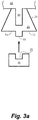
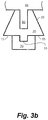
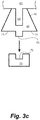
Figures 3a-3c are front elevation views of the device ofFigure 1 in use in accordance with some embodiments of the presently disclosed subject matter. - The presently disclosed subject matter will now be described more fully hereinafter with reference to the following description, in which some (but not all) embodiments are shown. The presently disclosed subject matter can, however, be embodied in different forms and should not be construed as limited to the embodiments set forth herein. Rather, these embodiments are provided so that the instant disclosure will be thorough and complete, and will fully convey the scope of the embodiments to those of ordinary skill in the art.
- Unless otherwise defined, all technical and scientific terms used herein have the same meaning as commonly understood by one of ordinary skill in the art to which the presently disclosed subject matter pertains. All publications, patent applications, patents, and other references mentioned herein are incorporated by reference in their entireties.
- Following long standing patent law convention, the terms "a", "an", and "the" mean "one or more" when used in the subject application, including the claims.
- The term "about" as used herein, when referring to a value or to an amount of mass, weight, time, volume, diameter, or percentage is meant to encompass variations of +/- 20%, 10%, 5%, 1%, or 0.1% from the specified amount, as such variations are appropriate to perform the disclosed method.
- The term "bottom" as used herein refers to a location on the presently disclosed device along the lower surface thereof, as shown in the orientation depicted in the Figures. The bottom face of the disclosed device is the face that includes the support member. The top face is positioned opposite to the bottom face.
- The term "channel" as used herein refers to an unfilled space suitable for housing a vehicle jack point.
- The terms "comprises" and "comprising" are intended to mean "includes", "including" and the like.
- The term "coupling" as used herein refers to the joining of two elements, either permanently or temporarily.
- As used herein, the term "jack point" refers to the proper location on a vehicle where a jack is to make contact with the vehicle during operation of the jack. In some embodiments, the term jack point is the optimal location on the vehicle frame where the jack acts during operation and raising of the vehicle. In some embodiments, the jack point can be a pinch weld.
- As used herein, the phrase "permanently attached" refers to an attachment that is not intended to be removed.
- As used herein, the term "receiving element" refers to an element of a car jack that houses a support member as set forth herein. For example, in some embodiments, the receiving element can comprise a lock-fit arrangement with the support member, clamps, or other components that releasably grasp the support member, and/or a housing into which the support member is coupled for a desired amount of time.
- The term "support member" as used herein refers to an element through which a vehicle jack supports a vehicle. In some embodiments, a support member of the presently disclosed subject matter can be coupled to a vehicle jack to raise and/or lower the vehicle.
- The term "top" as used herein refers to a location on the presently disclosed device along the upper surface thereof as seen in the orientation shown in the Figures. The top face of the disclosed device is the face that includes the channel. The top face is positioned opposite to the bottom face.
- The term "vehicle" as used herein refers to any motorized or other structure likely to travel, such as cars, vans, buses, trucks, motorcycles, off-road recreational vehicles, tractors, and the like.
- As used herein, the term "vehicle jack" or "jack" refers to any type of apparatus used to raise, lower, level, or support a vehicle. In some embodiments, the vehicle jack can include (but is not limited to) a crank jack, electric jack, hydraulic jack, trailer tongue jack, scissors-type jack, screw-type jack, and the like.
- The presently disclosed subject matter is directed to a device used to enable proper positioning of a vehicle jack underneath a vehicle. Particularly,
Figure 1 illustrates a jack positioning device in accordance with some embodiments of the presently disclosed subject matter. Specifically,device 5 includes top face 10 (which functions as the vehicle-engaging face of the device), bottom face 15 (which functions as the jack-engaging face of the device),front face 20,rear face 25, andsides 30. In some embodiments,device 5 is disposed in a generally upright position, withbottom face 15 facing downwards andtop face 10 facing upwards. In some embodiments,top face 10 andbottom face 15 are disposed about parallel to each other. In some embodiments,front face 20 andrear face 25 are disposed about parallel to each other. In some embodiments, the front face is disposed about perpendicularly to the top face and/or bottom face. In some embodiments, the rear face is disposed about perpendicularly to the top face and/or bottom face. -
Top face 10 compriseschannel 35 comprisinginner surface 40,top channel opening 45, andbottom partition 50, opposite to the top channel opening. In some embodiments, the channel can span the distance between the front and rear faces, as shown inFigure 1 . In some embodiments, the channel is of a uniform width. However, in some embodiments, the width ofchannel 35 can taper to accommodate a variety of jack points of varying widths.Channel 35 is configured to receive a vehicle jack point. In some embodiments, the vehicle jack point comprises a width and depth that is approximately the same width and depth aschannel 35, such that the jack point is capable of fitting closely into the channel. - Thus,
channel 35 can be configured in any desirable shape to cooperate with a vehicle jack point, including (but not limited to) a circular, rectangular, square, oblong, etc. cross-section. In some embodiments,channel 35 and the vehicle jack point have the same cross-sectional size and/or shape. Thus,channel 35 is sized and shaped to be affixed to a vehicle jack point (i.e., the jack point fits into the channel and is permanently maintained in position in some embodiments). In some embodiments, the channel extends substantially perpendicularly to the front and/or rear faces of the device. It should be appreciated thatchannel 35 can be configured to allowdevice 5 to be adapted for use on all types of vehicles, without limitation. - Bottom face 15 of
device 5 comprises a protrusion (support member 55) that projects away from bottom face 15 (i.e., outward from the device) and is adapted to cooperate with a vehicle jack. In some embodiments, the support member is approximately centrally located onbottom face 15, i.e., about equidistant from sides 30. In some embodiments,support member 55 extends fromfront face 20 torear face 25 onbottom face 15. In some embodiments, the support member is positioned perpendicularly to the bottom face of the device. The support member cooperates with the receiving element of a vehicle jack. It should be appreciated thatsupport member 55 provides the support structure for the vehicle jack. Particularly, the support member is at least partially or fully contained within a vehicle jack receiving element. In some embodiments, the jack comprises a receiving element sized and shaped to engage with the support member, and two contact surfaces that contact the bottom surface of the device when the receiving element is engaged with the protrusion. In some embodiments,support member 55 can include a nonslip or friction-resistant coating applied to the surface to maintain engagement with the vehicle jack. Such coatings are well known to those of ordinary skill in the art. -
Support member 55 can be configured in any desirable shape to cooperate with the receiving element of a vehicle jack, including (but not limited to) a rectangular, square, oblong, etc. cross-section. In some embodiments,support member 55 and the receiving element have about the same cross-sectional size and/or shape. Thus,support member 55 can be sized and shaped to be coupled with the receiving element of a vehicle jack. It should be appreciated thatsupport member 55 can be configured to allowdevice 5 to be adapted for use with all types of vehicle jacks, without limitation. -
Sides 30 ofdevice 5 can be shaped in any way desired. For example, in some embodiments, the device can include sloped sides spanning the distance betweentop face 10 andbottom face 15, as illustrated inFigure 1 . Thus, in some embodiments, sides 30 can comprise an angle of no more than (or no less than) about 5, 10, 15, 20, 25, 30, 35, 40, 45, 50, 55, 60, 65, 70, 75, 80, 85, 90, 95, 100, 105, 110, 115, 120, 125, 130, 135, 140, or 145 degrees, relative totop face 10 and/orbottom face 15. However, it should be appreciated that sides 30 are not required to be angled and can be configured in any shape known in the art. Similarly, it should be appreciated that the shape ofdevice 5 is not limited and can be configured in any form desired, so long as the device includeschannel 35 andsupport member 55. Further, the size ofdevice 5 is not limited. For example, in some embodiments, the device can have dimensions of about 5 cm x 5 cm x 5 cm (or about 2 inches x 2 inches x 2 inches) (length x width x height). - As illustrated in
Figures 2a and2b ,device 5 is mated withvehicle 65 such thatchannel 35 andvehicle jack point 60 are disposed in an abutting and aligned relationship relative to one another (i.e.,channel 35 is sized and shaped tohouse jack point 60, which can be a protruded element sized and shaped to fit into the channel). Particularly, as shown inFigure 2a ,device 5 and the vehicle are aligned such thatjack point 60 is positioned abovechannel 35. The device can then be elevated until the jack point is housed withinchannel 35. In some embodiments,channel 35 has a diameter that is slightly greater than the outer diameter ofjack point 60 such that the jack point freely but closely fits into the channel. Once in position (Figure 2b ), device 5 (via channel 35) can be permanently attached to the vehicle jack point using any method known in the art, including (but not limited to) adhesive bonding, welding, mechanical fasteners (i.e., bolting, riveting, clamping, etc.), engaging by fit and shape, and the like to ensure that the channel remains permanently positioned onvehicle jack point 60. For example, if an adhesive is utilized, it can be applied alongchannel interior 40 and/orchannel bottom partition 50 to engagevehicle jack point 60 and secure the device to the vehicle. Once channel is 35 attached to the vehicle jack point,device 5 is at the proper position for coopering with a vehicle jack to raise and/or lower the vehicle. Further, oncedevice 5 is attached to the vehicle jack point, a user can properly position a vehicle jack to the vehicle, even when conditions are such to prevent any adequate inspection.Device 5 can therefore be utilized in a manner to assure the safe and positive gripping of the vehicle by the jack during the elevating process, thus eliminating the hazards associated with improper positioning of the jack. - As shown in
Figures 3a and3b ,jack 70 can be positioned belowbottom face 15 ofdevice 5 to be in proper position to raise and lower the vehicle. Specifically, a selectedvehicle jack 70 is placed underneathvehicle 65, such thatjack receiving element 75 is positioned at a location below and aligned withsupport member 55, as illustrated inFigure 3a . The operator will then raise the jack until receivingelement 75 engagessupport member 55. In some embodiments, the support member is sized and shaped to cooperate with the receiving element of the jack, such that the support member is capable of fitting closely into the receiving element. In some embodiments,support member 55 and receivingelement 75 have about the same cross-sectional size and/or shape. Thus, the support member is sized and shaped to be housed within the receiving element of the jack. It should be appreciated that the support member is releasably housed in the receiving element of the jack such that a user can easily couple and uncouple the support member on demand. - Thus,
support member 55 is received and retained within receivingelement 75 ofjack 70 and is held in position for a desired amount of time (i.e., while the vehicle is raised, until the vehicle has been lowered, etc.). In this manner, the disclosed device prevents damage to vehicles caused by supporting the vehicles in non-approved jacking locations. Once the vehicle has been lowered, the jack can be detached fromsupport member 55 via uncoupling the support member and the receiving element, as shown inFigure 3c . - Therefore,
device 5 ensures proper positioning of a vehicle jack underneath a vehicle and ensures effective engagement with the appropriate part of the framework of the vehicle. Further, the device provides, among others, the advantages of increasing the degree of stability of the jack, reinforcing the jack at mechanically critical parts of the vehicle, and making it easier for the user to initially install the jack under the vehicle body. -
Device 5 can be constructed from any material known in the art to be rugged and durable, thereby ensuring many years of intended usage. The material used to constructdevice 5 should be capable of withstanding the force applied upon contact of the jack. Therefore, in some embodiments,device 5 can be constructed from metal, polymeric material, combinations thereof, and the like, as would be known in the art. For example, in some embodiments, the device can be constructed from a lightweight but high-strength metal, such as (but not limited to) aluminum, titanium, and/or alloys or combinations thereof. In some embodiments, the device can include bright colors and/or glow-in-the-dark areas (such as on and/or aroundsupport member 55 or bottom face 15) to assist users in correctly positioning the jack.Device 5 can be constructed using any of a wide variety of techniques, including (but not limited to) welding, injection molding, gas-assisted injection molding, extrusion, reaction-injection molding, slush molding, pour molding, blow molding, and/or casting using any of the materials described above. - The presently disclosed device is therefore relatively inexpensive to manufacture due to its simplicity of construction. It should be appreciated that
device 5 can be manufactured and installed as part of the original equipment of the vehicle, or can be readily attached to the vehicle later as an accessory item with a minimum of time and labor involved.
Claims (15)
- A method comprising:engaging a channel (35) defined in a top facing surface (10) of a jack point extension device (5) with a jack point (60) of a vehicle (65);providing translation forces to a bottom surface (15) of the jack point extension device (5) with a jack (70) by engaging a receiving element (75) of the jack (70) with a protrusion (55) extending from the bottom surface (15) and actuating the jack (70); andafter translation of the vehicle (65), disengaging the jack (70) from the protrusion (55) while the channel (35) of the jack point extension device (5) remains engaged with the jack point (60) of the vehicle (65).
- A method according to claim 1, wherein the protrusion (55) keeps the jack (70) from sliding out of position.
- A method according to claim 1 or claim 2, wherein the channel (35) is attached to the vehicle jack point (60) using an adhesive, welding, mechanical closures, or combinations thereof.
- A method according to any preceding claim, wherein the channel (35) extends from a front face (20) of the device to a rear face (25) of the device.
- A method according to any preceding claim, wherein the vehicle jack point (60) is a vehicle pinch weld.
- A method according to any preceding claim, wherein the channel (35) and the vehicle jack point (60) have about the same cross-sectional size, shape, or both.
- A method according to any preceding claim, wherein the receiving element (75) comprises a nonslip or friction-resistant coating, the protrusion (55) comprises a nonslip or friction-resistant coating, or both.
- A method according to any preceding claim, wherein the protrusion (55) is approximately centrally located on the bottom surface (15).
- A method according to any preceding claim, wherein the device (5) is constructed from metal, polymeric material, or combinations thereof.
- A method according to any preceding claim, wherein the jack (70) comprises a receiving element (75) sized and shaped to engage with the protrusion (55), and two contact surfaces that contact the bottom surface (15) of the device (5) when the receiving element (75) is engaged with the protrusion (55).
- A device (5) for attaching to a vehicle (65), said device (5) comprising:a. a top face (10) and a bottom face (15);b. a front face (20) and a rear face (25);c. a channel (35) disposed on the top face (10), wherein the channel (35) is sized and shaped to house a vehicle jack point (60); andd. a support member (55) disposed on the bottom face (15) and extending downward therefrom, wherein the support member (55) is sized and shaped to be housed within the receiving element (75) of a vehicle jack (70).
- A device (5) according to claim 11, wherein the top face (10) and the bottom face (15) are disposed substantially parallel to each other, the front face (20) and the rear face (25) are disposed substantially parallel to each other, or both.
- A device (5) according to claim 11 or claim 12, wherein the channel (35) extends on the top face (10) from the front face (20) to the rear face (25).
- A device (5) according to any of claims 11 to 13, wherein the support member (55) comprises a nonslip or friction-resistant coating.
- Combination of a device (5) according to any of claims 11 to 14 and a vehicle jack point (60), wherein the channel (35) and the vehicle jack point (60) have about the same cross sectional size and shape.
Applications Claiming Priority (1)
| Application Number | Priority Date | Filing Date | Title |
|---|---|---|---|
| US15/213,481 US10272887B2 (en) | 2016-07-19 | 2016-07-19 | Vehicle jack positioning device and methods of making and using the same |
Publications (2)
| Publication Number | Publication Date |
|---|---|
| EP3272628A2 true EP3272628A2 (en) | 2018-01-24 |
| EP3272628A3 EP3272628A3 (en) | 2018-02-21 |
Family
ID=59399239
Family Applications (1)
| Application Number | Title | Priority Date | Filing Date |
|---|---|---|---|
| EP17180911.4A Withdrawn EP3272628A3 (en) | 2016-07-19 | 2017-07-12 | Vehicle jack positioning device and methods of making and using the same |
Country Status (2)
| Country | Link |
|---|---|
| US (1) | US10272887B2 (en) |
| EP (1) | EP3272628A3 (en) |
Cited By (1)
| Publication number | Priority date | Publication date | Assignee | Title |
|---|---|---|---|---|
| FR3159580A1 (en) * | 2024-02-26 | 2025-08-29 | Stellantis Auto Sas | DEVICE TRANSVERSELY OFFSETTING A JACK PAD AT THE LEVEL OF A PORTION OF THE UNDERBODY OF A MOTOR VEHICLE |
Family Cites Families (14)
| Publication number | Priority date | Publication date | Assignee | Title |
|---|---|---|---|---|
| GB2089763A (en) | 1980-10-30 | 1982-06-30 | Shepherd John | Quick release caravan anchor jack |
| US4761984A (en) | 1986-09-26 | 1988-08-09 | Fuscaldo Jr Frank | Apparatus for supporting a vehicle for straightening and alignment |
| US5027639A (en) | 1990-01-16 | 1991-07-02 | Hinson Virgil H | Vehicle collision repair support rack |
| US5054307A (en) | 1990-09-25 | 1991-10-08 | Hein-Werner Corporation | Universal base member for securing vehicles for damage repair |
| US5623846A (en) | 1993-11-30 | 1997-04-29 | Brewer, Jr.; Clarence R. | Device for straightening a frame of an automobile |
| US6185982B1 (en) | 1999-12-01 | 2001-02-13 | Hein Werner Corporation | Apparatus for securing vehicle |
| US20030019273A1 (en) | 2001-07-25 | 2003-01-30 | Weschler Bradley R. | Automotive collision repair device |
| DE10143374A1 (en) | 2001-09-05 | 2003-03-20 | Veritas Gummiwerke Ag | Device for receiving a vehicle lifting device |
| US6722180B2 (en) | 2002-03-15 | 2004-04-20 | Bradley R. Weschler | Frame vehicle clamp adapter |
| US7017384B2 (en) | 2003-12-02 | 2006-03-28 | Michael Espinosa | Vehicle frame straightening jig |
| DE102006030769B3 (en) | 2006-06-30 | 2008-01-24 | Itw Automotive Products Gmbh & Co. Kg | Motor vehicle jack accommodating device, has set of locking sections deformed in area of another set of sections, where former set of sections locks latter set of sections when bolt is moved from releasing into locking position |
| DE102008012133A1 (en) | 2008-03-01 | 2009-09-03 | Daimler Ag | Lifting jack console for attachment to motor vehicle body i.e. side skirt, to lift all-terrain vehicle, has separate retaining element attached to fastening region of base body and adjusted by clamping screw relative to fastening region |
| US8132787B1 (en) | 2008-04-04 | 2012-03-13 | Robert Douglas Audet | Conical jack stands |
| CH708458B1 (en) | 2013-08-20 | 2017-09-29 | Erowa Ag | Tensioning device. |
-
2016
- 2016-07-19 US US15/213,481 patent/US10272887B2/en active Active
-
2017
- 2017-07-12 EP EP17180911.4A patent/EP3272628A3/en not_active Withdrawn
Non-Patent Citations (1)
| Title |
|---|
| None |
Cited By (1)
| Publication number | Priority date | Publication date | Assignee | Title |
|---|---|---|---|---|
| FR3159580A1 (en) * | 2024-02-26 | 2025-08-29 | Stellantis Auto Sas | DEVICE TRANSVERSELY OFFSETTING A JACK PAD AT THE LEVEL OF A PORTION OF THE UNDERBODY OF A MOTOR VEHICLE |
Also Published As
| Publication number | Publication date |
|---|---|
| US10272887B2 (en) | 2019-04-30 |
| EP3272628A3 (en) | 2018-02-21 |
| US20180022326A1 (en) | 2018-01-25 |
Similar Documents
| Publication | Publication Date | Title |
|---|---|---|
| CA2646851C (en) | Hitch installation hoist | |
| US20200131008A1 (en) | Device for removing, storing and installing convertible SUV hard tops and removable doors | |
| US20070228761A1 (en) | Cargo bed step | |
| US9783118B2 (en) | Mounting device for attaching a high lift jack to a vehicle | |
| US8720760B1 (en) | Heavy duty, leveraged spare tire carrier | |
| US11602960B2 (en) | Fifth wheel hitch | |
| US8851240B1 (en) | Wheel chock and method | |
| US8177252B2 (en) | Fifth wheel folding hitch | |
| US9108830B2 (en) | Secure connection load-rest for a ground-engaging vehicle jack | |
| US9868375B1 (en) | Receptacle for vehicles | |
| EP3272628A2 (en) | Vehicle jack positioning device and methods of making and using the same | |
| CA2072705C (en) | Fifth-wheel extension adapter | |
| NO20160818A1 (en) | Step platform device for connection to a trailer hitch ball | |
| US8333402B2 (en) | System for vehicle and trailer connection | |
| US7192007B2 (en) | Jack adapter | |
| US20070108246A1 (en) | Extendible hauling rack | |
| US20120313343A1 (en) | Ball mount step platform | |
| US6758485B1 (en) | Retractable hitch | |
| US20030011168A1 (en) | Hitch accessory | |
| CN215244794U (en) | Telescopic movable car stopper | |
| CA3040385A1 (en) | Jack stabilizer apparatus | |
| US9695848B2 (en) | Pinch weld clamp | |
| CN212300103U (en) | Climbing assault automobile-used upset antiskid guardrail | |
| US20160059913A1 (en) | Collapsible Towing Dolly | |
| DE19620380A1 (en) | Vehicle jacking system to raise vehicle |
Legal Events
| Date | Code | Title | Description |
|---|---|---|---|
| PUAI | Public reference made under article 153(3) epc to a published international application that has entered the european phase |
Free format text: ORIGINAL CODE: 0009012 |
|
| PUAL | Search report despatched |
Free format text: ORIGINAL CODE: 0009013 |
|
| AK | Designated contracting states |
Kind code of ref document: A2 Designated state(s): AL AT BE BG CH CY CZ DE DK EE ES FI FR GB GR HR HU IE IS IT LI LT LU LV MC MK MT NL NO PL PT RO RS SE SI SK SM TR |
|
| AX | Request for extension of the european patent |
Extension state: BA ME |
|
| AK | Designated contracting states |
Kind code of ref document: A3 Designated state(s): AL AT BE BG CH CY CZ DE DK EE ES FI FR GB GR HR HU IE IS IT LI LT LU LV MC MK MT NL NO PL PT RO RS SE SI SK SM TR |
|
| AX | Request for extension of the european patent |
Extension state: BA ME |
|
| RIC1 | Information provided on ipc code assigned before grant |
Ipc: B66F 3/12 20060101ALI20180118BHEP Ipc: B60S 11/00 20060101ALI20180118BHEP Ipc: B62D 25/20 20060101AFI20180118BHEP |
|
| STAA | Information on the status of an ep patent application or granted ep patent |
Free format text: STATUS: THE APPLICATION IS DEEMED TO BE WITHDRAWN |
|
| 18D | Application deemed to be withdrawn |
Effective date: 20180822 |