EP3272597A1 - Park brake system adjustment tool - Google Patents
Park brake system adjustment tool Download PDFInfo
- Publication number
- EP3272597A1 EP3272597A1 EP17174535.9A EP17174535A EP3272597A1 EP 3272597 A1 EP3272597 A1 EP 3272597A1 EP 17174535 A EP17174535 A EP 17174535A EP 3272597 A1 EP3272597 A1 EP 3272597A1
- Authority
- EP
- European Patent Office
- Prior art keywords
- lever
- brake
- gage block
- stop
- angle
- Prior art date
- Legal status (The legal status is an assumption and is not a legal conclusion. Google has not performed a legal analysis and makes no representation as to the accuracy of the status listed.)
- Granted
Links
Images


Classifications
-
- F—MECHANICAL ENGINEERING; LIGHTING; HEATING; WEAPONS; BLASTING
- F16—ENGINEERING ELEMENTS AND UNITS; GENERAL MEASURES FOR PRODUCING AND MAINTAINING EFFECTIVE FUNCTIONING OF MACHINES OR INSTALLATIONS; THERMAL INSULATION IN GENERAL
- F16C—SHAFTS; FLEXIBLE SHAFTS; ELEMENTS OR CRANKSHAFT MECHANISMS; ROTARY BODIES OTHER THAN GEARING ELEMENTS; BEARINGS
- F16C1/00—Flexible shafts; Mechanical means for transmitting movement in a flexible sheathing
- F16C1/10—Means for transmitting linear movement in a flexible sheathing, e.g. "Bowden-mechanisms"
- F16C1/22—Adjusting; Compensating length
- F16C1/223—Adjusting; Compensating length by adjusting the effective length of the flexible member
-
- B—PERFORMING OPERATIONS; TRANSPORTING
- B60—VEHICLES IN GENERAL
- B60T—VEHICLE BRAKE CONTROL SYSTEMS OR PARTS THEREOF; BRAKE CONTROL SYSTEMS OR PARTS THEREOF, IN GENERAL; ARRANGEMENT OF BRAKING ELEMENTS ON VEHICLES IN GENERAL; PORTABLE DEVICES FOR PREVENTING UNWANTED MOVEMENT OF VEHICLES; VEHICLE MODIFICATIONS TO FACILITATE COOLING OF BRAKES
- B60T7/00—Brake-action initiating means
- B60T7/02—Brake-action initiating means for personal initiation
- B60T7/08—Brake-action initiating means for personal initiation hand actuated
- B60T7/10—Disposition of hand control
- B60T7/108—Disposition of hand control with mechanisms to take up slack in the linkage to the brakes
-
- B—PERFORMING OPERATIONS; TRANSPORTING
- B60—VEHICLES IN GENERAL
- B60T—VEHICLE BRAKE CONTROL SYSTEMS OR PARTS THEREOF; BRAKE CONTROL SYSTEMS OR PARTS THEREOF, IN GENERAL; ARRANGEMENT OF BRAKING ELEMENTS ON VEHICLES IN GENERAL; PORTABLE DEVICES FOR PREVENTING UNWANTED MOVEMENT OF VEHICLES; VEHICLE MODIFICATIONS TO FACILITATE COOLING OF BRAKES
- B60T17/00—Component parts, details, or accessories of power brake systems not covered by groups B60T8/00, B60T13/00 or B60T15/00, or presenting other characteristic features
- B60T17/18—Safety devices; Monitoring
- B60T17/22—Devices for monitoring or checking brake systems; Signal devices
- B60T17/221—Procedure or apparatus for checking or keeping in a correct functioning condition of brake systems
-
- G—PHYSICS
- G01—MEASURING; TESTING
- G01B—MEASURING LENGTH, THICKNESS OR SIMILAR LINEAR DIMENSIONS; MEASURING ANGLES; MEASURING AREAS; MEASURING IRREGULARITIES OF SURFACES OR CONTOURS
- G01B3/00—Measuring instruments characterised by the use of mechanical techniques
- G01B3/30—Bars, blocks, or strips in which the distance between a pair of faces is fixed, although it may be preadjustable, e.g. end measure, feeler strip
- G01B3/32—Holders therefor
Definitions
- the present disclosure relates generally to the field of brake control system installation and adjustment.
- an aircraft dual park/emergency brake valve includes a lever coupled to a handle located in the cockpit of the aircraft via a cable.
- Proper adjustment of the cable may include moving the handle to a park locked position and using a measuring device, such as a caliper, to measure the distance between a positive stop on the brake valve and the lever of the brake valve. Further, proper adjustment may be achieved by a functional check.
- the system pressure may be monitored for variation from maximum system pressure. A variation from maximum system pressure may generally indicate that the system is not correctly adjusted.
- the cable may then be adjusted until a desired distance between the lever and the stop is achieved and/or until maximum system pressure is achieved with the park brake handle in park lock.
- the functional check may be conducted to determine that the maximum system pressure is achieved.
- a gage block tool for adjusting a brake cable may comprise a body comprising a first member extending in a first direction, the first member having a first length and a first thickness, and a second member extending in a second direction, the second member having a second length and a second thickness, wherein at least one of the first member or the second member are sized and configured to be placed between a stop and a lever of a brake valve, the brake cable connected between the lever and a brake handle being properly adjusted when the gage block sandwiched between the lever and the stop contacts both the lever and the stop while the brake handle is in a park lock position.
- the first length may be substantially equal to the second length.
- the first thickness may be substantially equal to the second thickness.
- the first member may comprise a first inner surface and the second member may comprise a second inner surface, the first inner surface being substantially perpendicular with respect to the second inner surface.
- the first member may comprise a first outer surface, the first outer surface being oriented at a first angle with respect to the first inner surface.
- the first angle may comprise a value of between zero and five degrees.
- the first angle may comprise a value of between zero and three degrees.
- the first angle may comprise a value of between 1.8 and 2.0 degrees.
- the second member may comprise a second outer surface, the second outer surface being oriented at a second angle with respect to the second inner surface. The first angle and the second angle may be substantially equal.
- a system for brake adjustment may comprise a brake valve having a lever and a stop, a brake cable operatively coupled to the lever and a brake handle, and a gage block having a first surface configured to contact the lever and a second surface configured to contact the stop when the brake handle is in a park lock position.
- the gage block may comprise a first member extending in a first direction, and a second member extending in a second direction.
- the first direction may be substantially perpendicular to the second direction.
- At least one of the first member or the second member may be configured to be located between the lever and a positive stop of the brake valve during adjustment of the brake cable.
- the first surface may be configured to contact the lever of the brake valve in response to the brake handle being moved to a park lock position.
- the first surface may be configured to be parallel to a surface of the lever in response to the lever contacting the first surface.
- the first member may comprise the first surface and an inner surface, the first surface being oriented at an angle with respect to the inner surface, the angle comprising a value of between zero and five degrees.
- a method for adjusting a brake cable may comprise placing a gage block between a stop and a lever of a brake valve, moving a brake handle connected to the lever by a brake cable to a park lock position, and adjusting the effective length of the brake cable such that the stop and the lever both contact the gage block.
- the adjusting the effective length of the brake cable may be in response to at least one of the lever contacting the gage block before the brake handle has reached the park lock position, or the brake valve lever not being in contact with the gage block in response to the brake handle being moved to the park lock position.
- the method may further comprise removing the gage block from between the stop and the lever in response to the stop and the lever both contacting the gage block.
- any reference to singular includes plural embodiments, and any reference to more than one component or step may include a singular embodiment or step.
- any reference to attached, fixed, connected or the like may include permanent, removable, temporary, partial, full and/or any other possible attachment option.
- any reference to without contact (or similar phrases) may also include reduced contact or minimal contact.
- Brake valve 100 may comprise a dual park/emergency brake valve. Brake valve 100 may comprise a valve for controlling hydraulic pressure being applied to a brake. Brake valve 100 may be located near the brakes of a vehicle. Brake valve 100 may comprise a plunger 102. Brake valve 100 may comprise a lever (also referred to herein as a brake lever) 110. Lever 110 may rotate about pivot 112. Plunger 102 may be configured to translate into and/or out brake valve 100.
- Plunger 102 may translate outwards (positive x-direction) from brake valve 100 in response to lever 110 rotating away from (clockwise direction in FIG. 1A ) brake valve 100. Plunger 102 may translate into (negative x-direction) brake valve 100 in response to lever 110 rotating towards (counter-clockwise direction in FIG. 1B ) brake valve 100.
- brake valve 100 may be in a closed, brake off position in response to plunger 102 being in an extended position, as illustrated in FIG. 1A .
- brake valve 100 may be in an open, brake on position in response to plunger 102 being in a contracted position, as illustrated in FIG. 1B . Hydraulic pressure being supplied to a brake may increase in response to brake valve 100 moving from a closed position to an open position.
- a cable 120 may be coupled to lever 110.
- Cable 120 may comprise a steel ribbon.
- Cable 120 may comprise a push/pull cable.
- cable 120 may operate in response to a pushing force and in response to a pulling force.
- Cable 120 may be coupled to a handle (also referred to herein as brake handle) 140.
- Handle 140 may be located in the cockpit of an aircraft, for example.
- Handle 140 may comprise a park/emergency handle.
- Handle 140 may be operatively coupled to lever 110 via cable 120.
- lever 110 may be configured to be located in the closed, brake off position, as illustrated in FIG. 1A , in response to handle 140 being in the stow position.
- lever 110 may be configured to be located in the open, brake on position, as illustrated in FIG. 1B , in response to handle 140 being in the park lock position.
- the park lock position may correspond to a position of handle 140, wherein in response to handle 140 being in the park lock position, brake valve 100 is in a fully open position.
- brake valve 100 may comprise a stop (also referred to herein as a positive stop) 104.
- gage block tool 130 may be placed over stop 104.
- Handle 140 may be moved to a park lock position, as illustrated in FIG. 1B .
- Cable 120 may be adjusted in response to lever 110 contacting gage block tool 130 prior to handle 140 reaching the park lock position.
- cable 120 may be lengthened in response to lever 110 contacting gage block tool 130 prior to handle 140 reaching the park lock position.
- Cable 120 may be adjusted in response to lever 110 not contacting gage block tool 130 when handle 140 is in the park lock position.
- cable 120 may be shortened in response to lever 110 not contacting gage block tool 130 when handle 140 is in the park lock position.
- cable 120 may be properly adjusted in response to gage block tool 130 being sandwiched between stop 104 and lever 110 in response to handle 140 being moved to the park lock position.
- gage block tool 130 of FIG. 1B a close-up view of gage block tool 130 of FIG. 1B is illustrated.
- lever 110 may contact gage block tool 130 in response to handle 140 (see FIG. 1B ) being in the park lock position and cable 120 (see FIG. 1B ) being properly adjusted.
- cable 120 may be properly adjusted in response to surface 114 of lever 110 contacting, and being substantially parallel to, outer surface 132 of gage block tool 130 when handle 140 (see FIG. 1B ) is in the park lock position.
- surface 114 of lever 110 may contact outer surface 132 of gage block tool 130.
- Outer surface 132 may be substantially (within 0.5 degrees) parallel to surface 114 in response to outer surface 132 contacting surface 114.
- stop 104 may comprise a member 106.
- member 106 may comprise an adjustable member.
- Member 106 may comprise a bolt.
- Gage block tool 130 may contact end 108 of member 106.
- Gage block tool 130 may extend over (in the negative y-direction) end 108.
- Gage block tool 130 may contact top surface 105 of stop 104.
- Gage block tool 330 may comprise a solid body 300 having a first member 301 extending in a first direction (negative x-direction) and a second member 302 extending in a second direction (negative y-direction).
- First member 301 may comprise a first outer surface 310 and a first inner surface 312.
- First outer surface 310 may comprise a length L1.
- First inner surface 312 may comprise a length L3.
- Second member 302 may comprise a second outer surface 314 and a second inner surface 316.
- Second outer surface 314 may comprise a length L2.
- Second inner surface 316 may comprise a length L4.
- length L1 may be substantially equal to length L2.
- length L3 may be substantially equal to length L4.
- First inner surface 312 may be oriented substantially (within 0.5 degrees) perpendicular to second inner surface 316.
- First member 301 may comprise a thickness T1.
- Second member may comprise a thickness T2.
- Thickness T1 may be measured at an end of first member 301 as illustrated in FIG. 3 .
- Thickness T2 may be measured at an end of second member 302 as illustrated in FIG. 3 .
- thickness T1 may comprise a minimum thickness of first member 301.
- thickness T2 may comprise a minimum thickness of second member 302.
- thickness T1 may be substantially equal to thickness T2, wherein the term substantially in this regard may mean that thickness T1 may be within 99% to 101% of the thickness of T2.
- first member 301 or second member 302 may be configured to be located between stop 104 (see FIG. 2 ) and lever 110 (see FIG. 2 ).
- gage block tool 330 may comprise a symmetrical geometry such that either first member 301 or second member 302 may be placed between stop 104 (see FIG. 2 ) and lever 110 (see FIG. 2 ).
- gage block tool 330 may be sized to be placed between stop 104 (see FIG. 2 ) and lever 110 (see FIG. 2 ).
- imaginary line 392 has been provided.
- Imaginary line 392 is parallel to first inner surface 312.
- first outer surface 310 may be oriented at a first angle ⁇ 1 with respect to imaginary line 392.
- first outer surface 310 may be oriented at a first angle ⁇ 1 with respect to first inner surface 312, in accordance with various embodiments.
- imaginary line 394 has been provided.
- Imaginary line 394 is parallel to second inner surface 316.
- second outer surface 314 may be oriented at a second angle ⁇ 2 with respect to imaginary line 394.
- second outer surface 314 may be oriented at a second angle ⁇ 2 with respect to second inner surface 316, in accordance with various embodiments.
- first angle ⁇ 1 may comprise a value of between zero and five degrees (0°-5°). In various embodiments, first angle ⁇ 1 may comprise a value of between zero and three degrees (0°-3°). In various embodiments, first angle ⁇ 1 may comprise a value of between one point eight and two point zero degrees (1.8°-2.0°). In various embodiments, second angle ⁇ 2 may comprise a value of between zero and five degrees (0°-5°). In various embodiments, second angle ⁇ 2 may comprise a value of between zero and three degrees (0°-3°). In various embodiments, second angle ⁇ 2 may comprise a value of between one point eight and two point zero degrees (1.8°-2.0°). In various embodiments, second angle ⁇ 2 may be substantially (within 0.2 degrees) equal to first angle ⁇ 1.
- second outer surface 314 may be configured to contact surface 114 of lever 110 and second inner surface 316 may be configured to contact end 108 of stop 104.
- thickness T2 may correspond to a desired distance between stop 104 and lever 110 in response to cable 120 (see FIG. 1B ) being properly adjusted.
- thickness T1 may correspond to a desired distance D between the stop 104 and the lever 110, in response to cable 120 (see FIG. 1B ) being properly adjusted. Adjusting cable 120 (see FIG. 1B ) such that lever 110 is spaced by desired distance D from stop 104 may ensure that full pressure is supplied to a brake in response to handle 140 being moved to the park lock position.
- Gage block tool 330 may comprise various steel alloys.
- Method 400 may include placing a gage block between a brake valve stop and a brake valve lever (step 402).
- Method 400 may include moving a brake handle to a park lock position (step 404).
- Method 400 may include adjusting an effective length of the brake cable (step 406).
- step 402 may include placing gage block tool 130 between stop 104 and lever 110.
- Step 404 may include moving handle 140 to the park lock position (as illustrated in FIG. 1B ).
- Step 406 may include adjusting the effective length of cable 120 such that the stop 104 and the lever 110 are both in contact with the gage block tool 130.
- cable 120 may be adjusted in response to lever 110 contacted gage block tool 130 prior to handle 140 reaching the park lock position. Cable 120 may be adjusted in response to lever 110 not contacting gage block tool 130 when handle 140 is in the park lock position.
- Gage block tool 130 may be removed from between the stop 104 and the lever 110 in response to the stop 104 and the lever 110 both contacting the gage block tool 130. Stated another way, the gage block tool 130 may be removed from between the stop 104 and the lever 110 after the adjustment process is complete.
- references to "various embodiments”, “one embodiment”, “an embodiment”, “an example embodiment”, etc. indicate that the embodiment described may include a particular feature, structure, or characteristic, but every embodiment may not necessarily include the particular feature, structure, or characteristic. Moreover, such phrases are not necessarily referring to the same embodiment. Further, when a particular feature, structure, or characteristic is described in connection with an embodiment, it is submitted that it is within the knowledge of one skilled in the art to affect such feature, structure, or characteristic in connection with other embodiments whether or not explicitly described. After reading the description, it will be apparent to one skilled in the relevant art(s) how to implement the disclosure in alternative embodiments.
Landscapes
- Engineering & Computer Science (AREA)
- Mechanical Engineering (AREA)
- Transportation (AREA)
- General Engineering & Computer Science (AREA)
- Health & Medical Sciences (AREA)
- Oral & Maxillofacial Surgery (AREA)
- Physics & Mathematics (AREA)
- General Physics & Mathematics (AREA)
- Transmission Of Braking Force In Braking Systems (AREA)
Abstract

Description
- The present disclosure relates generally to the field of brake control system installation and adjustment.
- Generally, an aircraft dual park/emergency brake valve includes a lever coupled to a handle located in the cockpit of the aircraft via a cable. Proper adjustment of the cable may include moving the handle to a park locked position and using a measuring device, such as a caliper, to measure the distance between a positive stop on the brake valve and the lever of the brake valve. Further, proper adjustment may be achieved by a functional check. With the park/emergency brake system installed and the park brake handle in park lock, the system pressure may be monitored for variation from maximum system pressure. A variation from maximum system pressure may generally indicate that the system is not correctly adjusted. The cable may then be adjusted until a desired distance between the lever and the stop is achieved and/or until maximum system pressure is achieved with the park brake handle in park lock. The functional check may be conducted to determine that the maximum system pressure is achieved.
- Systems and methods disclosed herein may be useful for brake cable adjustment. In this regard, a gage block tool for adjusting a brake cable may comprise a body comprising a first member extending in a first direction, the first member having a first length and a first thickness, and a second member extending in a second direction, the second member having a second length and a second thickness, wherein at least one of the first member or the second member are sized and configured to be placed between a stop and a lever of a brake valve, the brake cable connected between the lever and a brake handle being properly adjusted when the gage block sandwiched between the lever and the stop contacts both the lever and the stop while the brake handle is in a park lock position.
- In various embodiments, the first length may be substantially equal to the second length. The first thickness may be substantially equal to the second thickness. The first member may comprise a first inner surface and the second member may comprise a second inner surface, the first inner surface being substantially perpendicular with respect to the second inner surface. The first member may comprise a first outer surface, the first outer surface being oriented at a first angle with respect to the first inner surface. The first angle may comprise a value of between zero and five degrees. The first angle may comprise a value of between zero and three degrees. The first angle may comprise a value of between 1.8 and 2.0 degrees. The second member may comprise a second outer surface, the second outer surface being oriented at a second angle with respect to the second inner surface. The first angle and the second angle may be substantially equal.
- A system for brake adjustment may comprise a brake valve having a lever and a stop, a brake cable operatively coupled to the lever and a brake handle, and a gage block having a first surface configured to contact the lever and a second surface configured to contact the stop when the brake handle is in a park lock position.
- In various embodiments, the gage block may comprise a first member extending in a first direction, and a second member extending in a second direction. The first direction may be substantially perpendicular to the second direction. At least one of the first member or the second member may be configured to be located between the lever and a positive stop of the brake valve during adjustment of the brake cable. The first surface may be configured to contact the lever of the brake valve in response to the brake handle being moved to a park lock position. The first surface may be configured to be parallel to a surface of the lever in response to the lever contacting the first surface. The first member may comprise the first surface and an inner surface, the first surface being oriented at an angle with respect to the inner surface, the angle comprising a value of between zero and five degrees.
- A method for adjusting a brake cable may comprise placing a gage block between a stop and a lever of a brake valve, moving a brake handle connected to the lever by a brake cable to a park lock position, and adjusting the effective length of the brake cable such that the stop and the lever both contact the gage block.
- In various embodiments, the adjusting the effective length of the brake cable may be in response to at least one of the lever contacting the gage block before the brake handle has reached the park lock position, or the brake valve lever not being in contact with the gage block in response to the brake handle being moved to the park lock position. The method may further comprise removing the gage block from between the stop and the lever in response to the stop and the lever both contacting the gage block.
- The forgoing features and elements may be combined in various combinations without exclusivity, unless expressly indicated herein otherwise. These features and elements as well as the operation of the disclosed embodiments will become more apparent in light of the following description and accompanying drawings.
- Various embodiments are particularly pointed out and distinctly claimed in the concluding portion of the specification. Below is a summary of the drawing figures, wherein like numerals denote like elements and wherein:
-
FIG. 1A illustrates a gage block tool located on a park/emergency brake valve with the brake lever and brake valve in a closed, brake off position, and the park brake handle in the stow position, in accordance with various embodiments; -
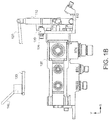
FIG. 1B illustrates a gage block tool located on a park/emergency brake valve with the brake lever and brake valve in an open, brake on position, and the park brake handle in the park lock position in accordance with various embodiments; -
FIG. 2 illustrates a close-up view of the gage block tool located on the park/emergency brake valve ofFIG. 1A , in accordance with various embodiments; -
FIG. 3 illustrates a gage block tool, in accordance with various embodiments; and -
FIG. 4 provides a method for adjusting a brake cable, in accordance with various embodiments. - The detailed description of exemplary embodiments herein makes reference to the accompanying drawings, which show exemplary embodiments by way of illustration. While these exemplary embodiments are described in sufficient detail to enable those skilled in the art to practice the disclosure, it should be understood that other embodiments may be realized and that logical changes and adaptations in design and construction may be made in accordance with this disclosure and the teachings herein without departing from the scope of the disclosure. Thus, the detailed description herein is presented for purposes of illustration only and not of limitation. For example, the steps recited in any of the method or process descriptions may be executed in any order and are not necessarily limited to the order presented. Moreover, many of the functions or steps may be outsourced to or performed by one or more third parties. Furthermore, any reference to singular includes plural embodiments, and any reference to more than one component or step may include a singular embodiment or step. Also, any reference to attached, fixed, connected or the like may include permanent, removable, temporary, partial, full and/or any other possible attachment option. Additionally, any reference to without contact (or similar phrases) may also include reduced contact or minimal contact.
- In the context of the present disclosure, methods may find particular use in connection with aircraft brake systems. However, various aspects of the disclosed embodiments may be adapted for optimized performance with a variety of components and in a variety of systems. As such, numerous applications of the present disclosure may be realized.
- With reference to
FIG. 1A andFIG. 1B , agage block tool 130 is illustrated with abrake valve 100 having alever 110 in the closed, brake off position and the open, brake on position, respectively, in accordance with various embodiments. An xy-axes is provided for ease of illustration.Brake valve 100 may comprise a dual park/emergency brake valve.Brake valve 100 may comprise a valve for controlling hydraulic pressure being applied to a brake.Brake valve 100 may be located near the brakes of a vehicle.Brake valve 100 may comprise aplunger 102.Brake valve 100 may comprise a lever (also referred to herein as a brake lever) 110.Lever 110 may rotate aboutpivot 112.Plunger 102 may be configured to translate into and/or outbrake valve 100.Plunger 102 may translate outwards (positive x-direction) frombrake valve 100 in response to lever 110 rotating away from (clockwise direction inFIG. 1A )brake valve 100.Plunger 102 may translate into (negative x-direction)brake valve 100 in response to lever 110 rotating towards (counter-clockwise direction inFIG. 1B )brake valve 100. In this regard,brake valve 100 may be in a closed, brake off position in response toplunger 102 being in an extended position, as illustrated inFIG. 1A . Conversely,brake valve 100 may be in an open, brake on position in response toplunger 102 being in a contracted position, as illustrated inFIG. 1B . Hydraulic pressure being supplied to a brake may increase in response tobrake valve 100 moving from a closed position to an open position. - In various embodiments, a cable (also referred to herein as a brake cable) 120 may be coupled to
lever 110.Cable 120 may comprise a steel ribbon.Cable 120 may comprise a push/pull cable. In this regard,cable 120 may operate in response to a pushing force and in response to a pulling force.Cable 120 may be coupled to a handle (also referred to herein as brake handle) 140. Handle 140 may be located in the cockpit of an aircraft, for example. Handle 140 may comprise a park/emergency handle. Handle 140 may be operatively coupled to lever 110 viacable 120. In this regard,lever 110 may be configured to be located in the closed, brake off position, as illustrated inFIG. 1A , in response to handle 140 being in the stow position. - Conversely,
lever 110 may be configured to be located in the open, brake on position, as illustrated inFIG. 1B , in response to handle 140 being in the park lock position. In various embodiments, the park lock position may correspond to a position ofhandle 140, wherein in response to handle 140 being in the park lock position,brake valve 100 is in a fully open position. - In various embodiments,
brake valve 100 may comprise a stop (also referred to herein as a positive stop) 104. During an installation or adjustment process ofcable 120,gage block tool 130 may be placed overstop 104. Handle 140 may be moved to a park lock position, as illustrated inFIG. 1B .Cable 120 may be adjusted in response to lever 110 contactinggage block tool 130 prior to handle 140 reaching the park lock position. For example,cable 120 may be lengthened in response to lever 110 contactinggage block tool 130 prior to handle 140 reaching the park lock position.Cable 120 may be adjusted in response to lever 110 not contactinggage block tool 130 whenhandle 140 is in the park lock position. For example,cable 120 may be shortened in response to lever 110 not contactinggage block tool 130 whenhandle 140 is in the park lock position. In this regard,cable 120 may be properly adjusted in response togage block tool 130 being sandwiched betweenstop 104 andlever 110 in response to handle 140 being moved to the park lock position. - With reference to
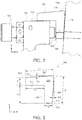
FIG. 2 , a close-up view ofgage block tool 130 ofFIG. 1B is illustrated. As previously mentioned,lever 110 may contactgage block tool 130 in response to handle 140 (seeFIG. 1B ) being in the park lock position and cable 120 (seeFIG. 1B ) being properly adjusted. In other words,cable 120 may be properly adjusted in response tosurface 114 oflever 110 contacting, and being substantially parallel to,outer surface 132 ofgage block tool 130 when handle 140 (seeFIG. 1B ) is in the park lock position. In this regard,surface 114 oflever 110 may contactouter surface 132 ofgage block tool 130.Outer surface 132 may be substantially (within 0.5 degrees) parallel to surface 114 in response toouter surface 132 contactingsurface 114. - In various embodiments, stop 104 may comprise a
member 106. In various embodiments,member 106 may comprise an adjustable member.Member 106 may comprise a bolt.Gage block tool 130 may contact end 108 ofmember 106.Gage block tool 130 may extend over (in the negative y-direction)end 108.Gage block tool 130 may contacttop surface 105 ofstop 104. - With reference to
FIG. 3 , a cross-section view ofgage block tool 330 is illustrated.Gage block tool 330 may comprise asolid body 300 having afirst member 301 extending in a first direction (negative x-direction) and asecond member 302 extending in a second direction (negative y-direction).First member 301 may comprise a firstouter surface 310 and a firstinner surface 312. Firstouter surface 310 may comprise a length L1. Firstinner surface 312 may comprise a length L3.Second member 302 may comprise a secondouter surface 314 and a secondinner surface 316. Secondouter surface 314 may comprise a length L2. Secondinner surface 316 may comprise a length L4. In various embodiments, length L1 may be substantially equal to length L2. In various embodiments, length L3 may be substantially equal to length L4. Firstinner surface 312 may be oriented substantially (within 0.5 degrees) perpendicular to secondinner surface 316.First member 301 may comprise a thickness T1. Second member may comprise a thickness T2. Thickness T1 may be measured at an end offirst member 301 as illustrated inFIG. 3 . Thickness T2 may be measured at an end ofsecond member 302 as illustrated inFIG. 3 . In various embodiments, thickness T1 may comprise a minimum thickness offirst member 301. In various embodiments, thickness T2 may comprise a minimum thickness ofsecond member 302. In various embodiments, thickness T1 may be substantially equal to thickness T2, wherein the term substantially in this regard may mean that thickness T1 may be within 99% to 101% of the thickness of T2. In this regard, eitherfirst member 301 orsecond member 302 may be configured to be located between stop 104 (seeFIG. 2 ) and lever 110 (seeFIG. 2 ). In this regard,gage block tool 330 may comprise a symmetrical geometry such that eitherfirst member 301 orsecond member 302 may be placed between stop 104 (seeFIG. 2 ) and lever 110 (seeFIG. 2 ). Similarly,gage block tool 330 may be sized to be placed between stop 104 (seeFIG. 2 ) and lever 110 (seeFIG. 2 ). - For clarity purposes,
imaginary line 392 has been provided.Imaginary line 392 is parallel to firstinner surface 312. In various embodiments, firstouter surface 310 may be oriented at a first angle Θ1 with respect toimaginary line 392. In this regard, firstouter surface 310 may be oriented at a first angle Θ1 with respect to firstinner surface 312, in accordance with various embodiments. For clarity purposes,imaginary line 394 has been provided.Imaginary line 394 is parallel to secondinner surface 316. In various embodiments, secondouter surface 314 may be oriented at a second angle Θ2 with respect toimaginary line 394. In this regard, secondouter surface 314 may be oriented at a second angle Θ2 with respect to secondinner surface 316, in accordance with various embodiments. In various embodiments, first angle Θ1 may comprise a value of between zero and five degrees (0°-5°). In various embodiments, first angle Θ1 may comprise a value of between zero and three degrees (0°-3°). In various embodiments, first angle Θ1 may comprise a value of between one point eight and two point zero degrees (1.8°-2.0°). In various embodiments, second angle Θ2 may comprise a value of between zero and five degrees (0°-5°). In various embodiments, second angle Θ2 may comprise a value of between zero and three degrees (0°-3°). In various embodiments, second angle Θ2 may comprise a value of between one point eight and two point zero degrees (1.8°-2.0°). In various embodiments, second angle Θ2 may be substantially (within 0.2 degrees) equal to first angle Θ1. - In various embodiments, with combined reference to
FIG. 2 and FIG. 3 , secondouter surface 314 may be configured to contactsurface 114 oflever 110 and secondinner surface 316 may be configured to contactend 108 ofstop 104. In this regard, thickness T2 may correspond to a desired distance betweenstop 104 andlever 110 in response to cable 120 (seeFIG. 1B ) being properly adjusted. Stated another way, thickness T1 may correspond to a desired distance D between thestop 104 and thelever 110, in response to cable 120 (seeFIG. 1B ) being properly adjusted. Adjusting cable 120 (seeFIG. 1B ) such thatlever 110 is spaced by desired distance D fromstop 104 may ensure that full pressure is supplied to a brake in response to handle 140 being moved to the park lock position.Gage block tool 330 may comprise various steel alloys. - With reference to
FIG. 4 , amethod 400 for adjusting a brake cable is illustrated, in accordance with various embodiments.Method 400 may include placing a gage block between a brake valve stop and a brake valve lever (step 402).Method 400 may include moving a brake handle to a park lock position (step 404).Method 400 may include adjusting an effective length of the brake cable (step 406). - In various embodiments, with combined reference to
FIG. 1B andFIG. 4 , step 402 may include placinggage block tool 130 betweenstop 104 andlever 110. Step 404 may include movinghandle 140 to the park lock position (as illustrated inFIG. 1B ). Step 406 may include adjusting the effective length ofcable 120 such that thestop 104 and thelever 110 are both in contact with thegage block tool 130. As previously discussed,cable 120 may be adjusted in response to lever 110 contactedgage block tool 130 prior to handle 140 reaching the park lock position.Cable 120 may be adjusted in response to lever 110 not contactinggage block tool 130 whenhandle 140 is in the park lock position.Gage block tool 130 may be removed from between thestop 104 and thelever 110 in response to thestop 104 and thelever 110 both contacting thegage block tool 130. Stated another way, thegage block tool 130 may be removed from between thestop 104 and thelever 110 after the adjustment process is complete. - Benefits, other advantages, and solutions to problems have been described herein with regard to specific embodiments. Furthermore, the connecting lines shown in the various figures contained herein are intended to represent exemplary functional relationships and/or physical couplings between the various elements. It should be noted that many alternative or additional functional relationships or physical connections may be present in a practical system. However, the benefits, advantages, solutions to problems, and any elements that may cause any benefit, advantage, or solution to occur or become more pronounced are not to be construed as critical, required, or essential features or elements of the disclosure. The scope of the disclosure is accordingly to be limited by nothing other than the appended claims, in which reference to an element in the singular is not intended to mean "one and only one" unless explicitly so stated, but rather "one or more." Moreover, where a phrase similar to "at least one of A, B, or C" is used in the claims, it is intended that the phrase be interpreted to mean that A alone may be present in an embodiment, B alone may be present in an embodiment, C alone may be present in an embodiment, or that any combination of the elements A, B and C may be present in a single embodiment; for example, A and B, A and C, B and C, or A and B and C.
- Systems, methods and apparatus are provided herein. In the detailed description herein, references to "various embodiments", "one embodiment", "an embodiment", "an example embodiment", etc., indicate that the embodiment described may include a particular feature, structure, or characteristic, but every embodiment may not necessarily include the particular feature, structure, or characteristic. Moreover, such phrases are not necessarily referring to the same embodiment. Further, when a particular feature, structure, or characteristic is described in connection with an embodiment, it is submitted that it is within the knowledge of one skilled in the art to affect such feature, structure, or characteristic in connection with other embodiments whether or not explicitly described. After reading the description, it will be apparent to one skilled in the relevant art(s) how to implement the disclosure in alternative embodiments. Furthermore, no element, component, or method step in the present disclosure is intended to be dedicated to the public regardless of whether the element, component, or method step is explicitly recited in the claims. As used herein, the terms "comprises", "comprising", or any other variation thereof, are intended to cover a non-exclusive inclusion, such that a process, method, article, or apparatus that comprises a list of elements does not include only those elements but may include other elements not expressly listed or inherent to such process, method, article, or apparatus
Claims (15)
- A gage block tool (330) for adjusting a brake cable comprising:a body (300) comprising:a first member (301) extending in a first direction, the first member having a first length and a first thickness; anda second member (302) extending in a second direction, the second member having a second length and a second thickness,wherein at least one of the first member (301) or the second member (302) are sized and configured to be placed between a stop (104) and a lever (110) of a brake valve, the brake cable connected between the lever and a brake handle being properly adjusted when the gage block sandwiched between the lever (110) and the stop (104) contacts both the lever (110) and the stop (104) while the brake handle is in a park lock position.
- The gage block tool of claim 1, wherein the first length is substantially equal to the second length.
- The gage block tool of claim 1, wherein the first thickness is substantially equal to the second thickness.
- The gage block tool of claim 1, wherein the first member (301) comprises a first inner surface and the second member comprises a second inner surface, the first inner surface being substantially perpendicular with respect to the second inner surface.
- The gage block tool of claim 4, wherein the first member (301) comprises a first outer surface, the first outer surface being oriented at a first angle with respect to the first inner surface.
- The gage block tool of claim 5, wherein the first angle comprises a value of between zero and five degrees; or wherein the first angle comprises a value of between zero and three degrees; or wherein the first angle comprises a value of between 1.8 and 2.0 degrees.
- The gage block tool of claim 5, wherein the second member (302) comprises a second outer surface, the second outer surface being oriented at a second angle with respect to the second inner surface, and preferably wherein the first angle and the second angle are substantially equal.
- A system for brake adjustment comprising:a brake valve having a lever (110) and a stop (104);a brake cable operatively coupled to the lever anda brake handle; anda gage block (130) having a first surface configured to contact the lever and a second surface configured to contact the stop when the brake handle is in a park lock position.
- The system of claim 8, wherein the gage block comprises:a first member (301) extending in a first direction; anda second member (302) extending in a second direction.
- The system of claim 9, wherein the first direction is substantially perpendicular to the second direction; or wherein at least one of the first member (301) or the second member (302) are configured to be located between the lever and a positive stop of the brake valve during adjustment of the brake cable.
- The system of claim 8, wherein the first surface is configured to contact the lever of the brake valve in response to the brake handle being moved to the park lock position; or wherein the first surface is configured to be parallel to a surface of the lever in response to the lever contacting the first surface.
- The system of claim 9, wherein the first member (301) comprises the first surface and an inner surface, the first surface being oriented at an angle with respect to the inner surface, the angle comprising a value of between zero and five degrees.
- A method for adjusting a brake cable comprising:placing a gage block between a stop and a lever of a brake valve;moving a brake handle connected to the lever by a brake cable to a park lock position; andadjusting the effective length of the brake cable such that the stop and the lever both contact the gage block.
- The method of claim 13, wherein the adjusting the effective length of the brake cable is in response to at least one of:the lever contacting the gage block before the brake handle has reached the park lock position, orthe brake valve lever not being in contact with the gage block in response to the brake handle being moved to the park lock position.
- The method of claim 13, further comprising removing the gage block from between the stop and the lever in response to the stop and the lever both contacting the gage block.
Applications Claiming Priority (1)
| Application Number | Priority Date | Filing Date | Title |
|---|---|---|---|
| US15/217,502 US10001159B2 (en) | 2016-07-22 | 2016-07-22 | Park brake system adjustment tool |
Publications (2)
| Publication Number | Publication Date |
|---|---|
| EP3272597A1 true EP3272597A1 (en) | 2018-01-24 |
| EP3272597B1 EP3272597B1 (en) | 2019-03-06 |
Family
ID=59030800
Family Applications (1)
| Application Number | Title | Priority Date | Filing Date |
|---|---|---|---|
| EP17174535.9A Active EP3272597B1 (en) | 2016-07-22 | 2017-06-06 | Park brake system adjustment tool |
Country Status (2)
| Country | Link |
|---|---|
| US (1) | US10001159B2 (en) |
| EP (1) | EP3272597B1 (en) |
Citations (6)
| Publication number | Priority date | Publication date | Assignee | Title |
|---|---|---|---|---|
| EP1380487A1 (en) * | 2002-07-12 | 2004-01-14 | Integrated Display Systems Limited | Handbrake cable adjustment system |
| EP1731790A1 (en) * | 2005-06-10 | 2006-12-13 | GM Global Technology Operations, Inc. | Manual adjuster for parking brake |
| EP2011705A1 (en) * | 2007-07-02 | 2009-01-07 | Peugeot Citroen Automobiles SA | Method of adjusting a secondary brake |
| KR20130026746A (en) * | 2011-09-06 | 2013-03-14 | 현대자동차주식회사 | Tension balancer of cable for parking-brake |
| WO2013163458A2 (en) * | 2012-04-25 | 2013-10-31 | Innovative System Solutions, Inc | Apparatus, system and method for tensioning an emergency brake system |
| US20130291356A1 (en) * | 2012-05-03 | 2013-11-07 | GM Global Technology Operations LLC | Method of tensioning park brake cables |
Family Cites Families (10)
| Publication number | Priority date | Publication date | Assignee | Title |
|---|---|---|---|---|
| DE2927423C2 (en) * | 1979-07-06 | 1984-08-23 | Alfred Teves Gmbh, 6000 Frankfurt | Dual circuit pressure regulator |
| DE3009288A1 (en) * | 1980-03-11 | 1981-09-17 | Alfred Teves Gmbh, 6000 Frankfurt | TWO-CIRCUIT PRESSURE REGULATOR |
| DE3012765A1 (en) * | 1980-04-02 | 1981-10-08 | Alfred Teves Gmbh, 6000 Frankfurt | TWO-CIRCUIT PRESSURE REGULATOR FOR HYDRAULIC BRAKE SYSTEMS |
| US4757300A (en) * | 1984-05-02 | 1988-07-12 | Adam Sebalos | Brake adjustment monitoring device for automotive vehicles |
| DE3418041A1 (en) * | 1984-05-15 | 1985-11-21 | Alfred Teves Gmbh, 6000 Frankfurt | METHOD FOR PRESETTING OR SETTING THE SWITCHING POINT OF A BRAKE PRESSURE CONTROL UNIT AND BRAKE PRESSURE CONTROL UNIT FOR A PRESSURE-OPERABLE VEHICLE BRAKE SYSTEM |
| GB0324571D0 (en) | 2003-10-22 | 2003-11-26 | Automotive Prod Italia Sv Srl | Parking brakes |
| JP4581980B2 (en) * | 2005-11-29 | 2010-11-17 | 株式会社豊田自動織機 | Parking brake operation notification device and parking brake adjustment method |
| DE202010006900U1 (en) | 2010-05-18 | 2011-10-07 | Power-Cast Light Metal Solutions Gmbh & Co. Kg | Actuation device for a parking brake |
| US9327698B2 (en) | 2012-04-27 | 2016-05-03 | Deere & Company | Tractor park brake force sensing system |
| US9921043B2 (en) * | 2016-01-19 | 2018-03-20 | Arvinmeritor Technology, Llc | Measurement tool and method of measuring brake stroke |
-
2016
- 2016-07-22 US US15/217,502 patent/US10001159B2/en active Active
-
2017
- 2017-06-06 EP EP17174535.9A patent/EP3272597B1/en active Active
Patent Citations (6)
| Publication number | Priority date | Publication date | Assignee | Title |
|---|---|---|---|---|
| EP1380487A1 (en) * | 2002-07-12 | 2004-01-14 | Integrated Display Systems Limited | Handbrake cable adjustment system |
| EP1731790A1 (en) * | 2005-06-10 | 2006-12-13 | GM Global Technology Operations, Inc. | Manual adjuster for parking brake |
| EP2011705A1 (en) * | 2007-07-02 | 2009-01-07 | Peugeot Citroen Automobiles SA | Method of adjusting a secondary brake |
| KR20130026746A (en) * | 2011-09-06 | 2013-03-14 | 현대자동차주식회사 | Tension balancer of cable for parking-brake |
| WO2013163458A2 (en) * | 2012-04-25 | 2013-10-31 | Innovative System Solutions, Inc | Apparatus, system and method for tensioning an emergency brake system |
| US20130291356A1 (en) * | 2012-05-03 | 2013-11-07 | GM Global Technology Operations LLC | Method of tensioning park brake cables |
Also Published As
| Publication number | Publication date |
|---|---|
| US10001159B2 (en) | 2018-06-19 |
| US20180023616A1 (en) | 2018-01-25 |
| EP3272597B1 (en) | 2019-03-06 |
Similar Documents
| Publication | Publication Date | Title |
|---|---|---|
| US8578766B2 (en) | Brake wear measurement apparatus and method | |
| US20160129567A1 (en) | Device for applying temporary fasteners | |
| US5398718A (en) | Tap line pliers | |
| US11585475B1 (en) | Dual cam lever hose clamp | |
| US11597363B2 (en) | Brake position system | |
| US7596846B2 (en) | Clamping fastener grip length indicator | |
| US10001159B2 (en) | Park brake system adjustment tool | |
| NZ203837A (en) | Alarm check valve for sandwiching between flanges of pipes in automatic sprinkler system | |
| EP3466780A2 (en) | Brake control system channel protection | |
| US20170009913A1 (en) | Edge protection bushing with integrated clamp | |
| US20150336247A1 (en) | Torque wrench adapter | |
| US9732815B2 (en) | Brake stroke logging indicator | |
| US9921043B2 (en) | Measurement tool and method of measuring brake stroke | |
| EP3036393A1 (en) | Slip on connector to seal pipe/casing | |
| CN111811705B (en) | Fixing device for strain rosette and residual stress detection method using same | |
| CN105737790A (en) | Device for measuring test hole compression deformation | |
| US10481047B2 (en) | Apparatus and method for testing a linear acuator | |
| CN114440023B (en) | Compression fittings with visual torque indicator | |
| EP2845798A1 (en) | Routings for articulated landing gear | |
| CA2470372A1 (en) | Measuring-point bolt | |
| EP2979942B1 (en) | Systems and methods for aircraft brake sensors | |
| CN205497269U (en) | A locking positioning that splines round pin mechanism for examining utensil | |
| US10493962B2 (en) | Brake position system | |
| US20250154989A1 (en) | Connection system for components having rotatable shafts | |
| CN220426917U (en) | Boring tool and boring lathe |
Legal Events
| Date | Code | Title | Description |
|---|---|---|---|
| PUAI | Public reference made under article 153(3) epc to a published international application that has entered the european phase |
Free format text: ORIGINAL CODE: 0009012 |
|
| STAA | Information on the status of an ep patent application or granted ep patent |
Free format text: STATUS: THE APPLICATION HAS BEEN PUBLISHED |
|
| AK | Designated contracting states |
Kind code of ref document: A1 Designated state(s): AL AT BE BG CH CY CZ DE DK EE ES FI FR GB GR HR HU IE IS IT LI LT LU LV MC MK MT NL NO PL PT RO RS SE SI SK SM TR |
|
| AX | Request for extension of the european patent |
Extension state: BA ME |
|
| STAA | Information on the status of an ep patent application or granted ep patent |
Free format text: STATUS: REQUEST FOR EXAMINATION WAS MADE |
|
| 17P | Request for examination filed |
Effective date: 20180724 |
|
| RBV | Designated contracting states (corrected) |
Designated state(s): AL AT BE BG CH CY CZ DE DK EE ES FI FR GB GR HR HU IE IS IT LI LT LU LV MC MK MT NL NO PL PT RO RS SE SI SK SM TR |
|
| RIC1 | Information provided on ipc code assigned before grant |
Ipc: B60T 17/22 20060101ALI20180814BHEP Ipc: B60T 7/10 20060101AFI20180814BHEP |
|
| GRAP | Despatch of communication of intention to grant a patent |
Free format text: ORIGINAL CODE: EPIDOSNIGR1 |
|
| STAA | Information on the status of an ep patent application or granted ep patent |
Free format text: STATUS: GRANT OF PATENT IS INTENDED |
|
| INTG | Intention to grant announced |
Effective date: 20180928 |
|
| GRAS | Grant fee paid |
Free format text: ORIGINAL CODE: EPIDOSNIGR3 |
|
| GRAA | (expected) grant |
Free format text: ORIGINAL CODE: 0009210 |
|
| STAA | Information on the status of an ep patent application or granted ep patent |
Free format text: STATUS: THE PATENT HAS BEEN GRANTED |
|
| AK | Designated contracting states |
Kind code of ref document: B1 Designated state(s): AL AT BE BG CH CY CZ DE DK EE ES FI FR GB GR HR HU IE IS IT LI LT LU LV MC MK MT NL NO PL PT RO RS SE SI SK SM TR |
|
| REG | Reference to a national code |
Ref country code: GB Ref legal event code: FG4D |
|
| REG | Reference to a national code |
Ref country code: CH Ref legal event code: EP Ref country code: AT Ref legal event code: REF Ref document number: 1104115 Country of ref document: AT Kind code of ref document: T Effective date: 20190315 |
|
| REG | Reference to a national code |
Ref country code: DE Ref legal event code: R096 Ref document number: 602017002464 Country of ref document: DE |
|
| REG | Reference to a national code |
Ref country code: IE Ref legal event code: FG4D |
|
| REG | Reference to a national code |
Ref country code: NL Ref legal event code: MP Effective date: 20190306 |
|
| REG | Reference to a national code |
Ref country code: LT Ref legal event code: MG4D |
|
| PG25 | Lapsed in a contracting state [announced via postgrant information from national office to epo] |
Ref country code: SE Free format text: LAPSE BECAUSE OF FAILURE TO SUBMIT A TRANSLATION OF THE DESCRIPTION OR TO PAY THE FEE WITHIN THE PRESCRIBED TIME-LIMIT Effective date: 20190306 Ref country code: LT Free format text: LAPSE BECAUSE OF FAILURE TO SUBMIT A TRANSLATION OF THE DESCRIPTION OR TO PAY THE FEE WITHIN THE PRESCRIBED TIME-LIMIT Effective date: 20190306 Ref country code: NO Free format text: LAPSE BECAUSE OF FAILURE TO SUBMIT A TRANSLATION OF THE DESCRIPTION OR TO PAY THE FEE WITHIN THE PRESCRIBED TIME-LIMIT Effective date: 20190606 Ref country code: FI Free format text: LAPSE BECAUSE OF FAILURE TO SUBMIT A TRANSLATION OF THE DESCRIPTION OR TO PAY THE FEE WITHIN THE PRESCRIBED TIME-LIMIT Effective date: 20190306 |
|
| PG25 | Lapsed in a contracting state [announced via postgrant information from national office to epo] |
Ref country code: GR Free format text: LAPSE BECAUSE OF FAILURE TO SUBMIT A TRANSLATION OF THE DESCRIPTION OR TO PAY THE FEE WITHIN THE PRESCRIBED TIME-LIMIT Effective date: 20190607 Ref country code: RS Free format text: LAPSE BECAUSE OF FAILURE TO SUBMIT A TRANSLATION OF THE DESCRIPTION OR TO PAY THE FEE WITHIN THE PRESCRIBED TIME-LIMIT Effective date: 20190306 Ref country code: BG Free format text: LAPSE BECAUSE OF FAILURE TO SUBMIT A TRANSLATION OF THE DESCRIPTION OR TO PAY THE FEE WITHIN THE PRESCRIBED TIME-LIMIT Effective date: 20190606 Ref country code: NL Free format text: LAPSE BECAUSE OF FAILURE TO SUBMIT A TRANSLATION OF THE DESCRIPTION OR TO PAY THE FEE WITHIN THE PRESCRIBED TIME-LIMIT Effective date: 20190306 Ref country code: LV Free format text: LAPSE BECAUSE OF FAILURE TO SUBMIT A TRANSLATION OF THE DESCRIPTION OR TO PAY THE FEE WITHIN THE PRESCRIBED TIME-LIMIT Effective date: 20190306 Ref country code: HR Free format text: LAPSE BECAUSE OF FAILURE TO SUBMIT A TRANSLATION OF THE DESCRIPTION OR TO PAY THE FEE WITHIN THE PRESCRIBED TIME-LIMIT Effective date: 20190306 |
|
| REG | Reference to a national code |
Ref country code: AT Ref legal event code: MK05 Ref document number: 1104115 Country of ref document: AT Kind code of ref document: T Effective date: 20190306 |
|
| PG25 | Lapsed in a contracting state [announced via postgrant information from national office to epo] |
Ref country code: IT Free format text: LAPSE BECAUSE OF FAILURE TO SUBMIT A TRANSLATION OF THE DESCRIPTION OR TO PAY THE FEE WITHIN THE PRESCRIBED TIME-LIMIT Effective date: 20190306 Ref country code: RO Free format text: LAPSE BECAUSE OF FAILURE TO SUBMIT A TRANSLATION OF THE DESCRIPTION OR TO PAY THE FEE WITHIN THE PRESCRIBED TIME-LIMIT Effective date: 20190306 Ref country code: CZ Free format text: LAPSE BECAUSE OF FAILURE TO SUBMIT A TRANSLATION OF THE DESCRIPTION OR TO PAY THE FEE WITHIN THE PRESCRIBED TIME-LIMIT Effective date: 20190306 Ref country code: AL Free format text: LAPSE BECAUSE OF FAILURE TO SUBMIT A TRANSLATION OF THE DESCRIPTION OR TO PAY THE FEE WITHIN THE PRESCRIBED TIME-LIMIT Effective date: 20190306 Ref country code: PT Free format text: LAPSE BECAUSE OF FAILURE TO SUBMIT A TRANSLATION OF THE DESCRIPTION OR TO PAY THE FEE WITHIN THE PRESCRIBED TIME-LIMIT Effective date: 20190706 Ref country code: SK Free format text: LAPSE BECAUSE OF FAILURE TO SUBMIT A TRANSLATION OF THE DESCRIPTION OR TO PAY THE FEE WITHIN THE PRESCRIBED TIME-LIMIT Effective date: 20190306 Ref country code: ES Free format text: LAPSE BECAUSE OF FAILURE TO SUBMIT A TRANSLATION OF THE DESCRIPTION OR TO PAY THE FEE WITHIN THE PRESCRIBED TIME-LIMIT Effective date: 20190306 Ref country code: EE Free format text: LAPSE BECAUSE OF FAILURE TO SUBMIT A TRANSLATION OF THE DESCRIPTION OR TO PAY THE FEE WITHIN THE PRESCRIBED TIME-LIMIT Effective date: 20190306 |
|
| PG25 | Lapsed in a contracting state [announced via postgrant information from national office to epo] |
Ref country code: SM Free format text: LAPSE BECAUSE OF FAILURE TO SUBMIT A TRANSLATION OF THE DESCRIPTION OR TO PAY THE FEE WITHIN THE PRESCRIBED TIME-LIMIT Effective date: 20190306 Ref country code: PL Free format text: LAPSE BECAUSE OF FAILURE TO SUBMIT A TRANSLATION OF THE DESCRIPTION OR TO PAY THE FEE WITHIN THE PRESCRIBED TIME-LIMIT Effective date: 20190306 |
|
| REG | Reference to a national code |
Ref country code: DE Ref legal event code: R097 Ref document number: 602017002464 Country of ref document: DE |
|
| PG25 | Lapsed in a contracting state [announced via postgrant information from national office to epo] |
Ref country code: IS Free format text: LAPSE BECAUSE OF FAILURE TO SUBMIT A TRANSLATION OF THE DESCRIPTION OR TO PAY THE FEE WITHIN THE PRESCRIBED TIME-LIMIT Effective date: 20190706 Ref country code: AT Free format text: LAPSE BECAUSE OF FAILURE TO SUBMIT A TRANSLATION OF THE DESCRIPTION OR TO PAY THE FEE WITHIN THE PRESCRIBED TIME-LIMIT Effective date: 20190306 |
|
| REG | Reference to a national code |
Ref country code: DE Ref legal event code: R119 Ref document number: 602017002464 Country of ref document: DE |
|
| PLBE | No opposition filed within time limit |
Free format text: ORIGINAL CODE: 0009261 |
|
| STAA | Information on the status of an ep patent application or granted ep patent |
Free format text: STATUS: NO OPPOSITION FILED WITHIN TIME LIMIT |
|
| PG25 | Lapsed in a contracting state [announced via postgrant information from national office to epo] |
Ref country code: MC Free format text: LAPSE BECAUSE OF FAILURE TO SUBMIT A TRANSLATION OF THE DESCRIPTION OR TO PAY THE FEE WITHIN THE PRESCRIBED TIME-LIMIT Effective date: 20190306 Ref country code: DK Free format text: LAPSE BECAUSE OF FAILURE TO SUBMIT A TRANSLATION OF THE DESCRIPTION OR TO PAY THE FEE WITHIN THE PRESCRIBED TIME-LIMIT Effective date: 20190306 |
|
| 26N | No opposition filed |
Effective date: 20191209 |
|
| PG25 | Lapsed in a contracting state [announced via postgrant information from national office to epo] |
Ref country code: SI Free format text: LAPSE BECAUSE OF FAILURE TO SUBMIT A TRANSLATION OF THE DESCRIPTION OR TO PAY THE FEE WITHIN THE PRESCRIBED TIME-LIMIT Effective date: 20190306 |
|
| REG | Reference to a national code |
Ref country code: BE Ref legal event code: MM Effective date: 20190630 |
|
| PG25 | Lapsed in a contracting state [announced via postgrant information from national office to epo] |
Ref country code: TR Free format text: LAPSE BECAUSE OF FAILURE TO SUBMIT A TRANSLATION OF THE DESCRIPTION OR TO PAY THE FEE WITHIN THE PRESCRIBED TIME-LIMIT Effective date: 20190306 |
|
| PG25 | Lapsed in a contracting state [announced via postgrant information from national office to epo] |
Ref country code: IE Free format text: LAPSE BECAUSE OF NON-PAYMENT OF DUE FEES Effective date: 20190606 Ref country code: DE Free format text: LAPSE BECAUSE OF NON-PAYMENT OF DUE FEES Effective date: 20200101 |
|
| PG25 | Lapsed in a contracting state [announced via postgrant information from national office to epo] |
Ref country code: BE Free format text: LAPSE BECAUSE OF NON-PAYMENT OF DUE FEES Effective date: 20190630 Ref country code: LU Free format text: LAPSE BECAUSE OF NON-PAYMENT OF DUE FEES Effective date: 20190606 |
|
| REG | Reference to a national code |
Ref country code: CH Ref legal event code: PL |
|
| PG25 | Lapsed in a contracting state [announced via postgrant information from national office to epo] |
Ref country code: LI Free format text: LAPSE BECAUSE OF NON-PAYMENT OF DUE FEES Effective date: 20200630 Ref country code: CH Free format text: LAPSE BECAUSE OF NON-PAYMENT OF DUE FEES Effective date: 20200630 |
|
| PG25 | Lapsed in a contracting state [announced via postgrant information from national office to epo] |
Ref country code: CY Free format text: LAPSE BECAUSE OF FAILURE TO SUBMIT A TRANSLATION OF THE DESCRIPTION OR TO PAY THE FEE WITHIN THE PRESCRIBED TIME-LIMIT Effective date: 20190306 |
|
| PG25 | Lapsed in a contracting state [announced via postgrant information from national office to epo] |
Ref country code: MT Free format text: LAPSE BECAUSE OF FAILURE TO SUBMIT A TRANSLATION OF THE DESCRIPTION OR TO PAY THE FEE WITHIN THE PRESCRIBED TIME-LIMIT Effective date: 20190306 Ref country code: HU Free format text: LAPSE BECAUSE OF FAILURE TO SUBMIT A TRANSLATION OF THE DESCRIPTION OR TO PAY THE FEE WITHIN THE PRESCRIBED TIME-LIMIT; INVALID AB INITIO Effective date: 20170606 |
|
| PG25 | Lapsed in a contracting state [announced via postgrant information from national office to epo] |
Ref country code: MK Free format text: LAPSE BECAUSE OF FAILURE TO SUBMIT A TRANSLATION OF THE DESCRIPTION OR TO PAY THE FEE WITHIN THE PRESCRIBED TIME-LIMIT Effective date: 20190306 |
|
| P01 | Opt-out of the competence of the unified patent court (upc) registered |
Effective date: 20230522 |
|
| PGFP | Annual fee paid to national office [announced via postgrant information from national office to epo] |
Ref country code: GB Payment date: 20250520 Year of fee payment: 9 |
|
| PGFP | Annual fee paid to national office [announced via postgrant information from national office to epo] |
Ref country code: FR Payment date: 20250520 Year of fee payment: 9 |