EP3272561A1 - Hydraulic shock absorber device for vehicle - Google Patents
Hydraulic shock absorber device for vehicle Download PDFInfo
- Publication number
- EP3272561A1 EP3272561A1 EP16764508.4A EP16764508A EP3272561A1 EP 3272561 A1 EP3272561 A1 EP 3272561A1 EP 16764508 A EP16764508 A EP 16764508A EP 3272561 A1 EP3272561 A1 EP 3272561A1
- Authority
- EP
- European Patent Office
- Prior art keywords
- hydraulic shock
- hydraulic
- pair
- vehicle
- oil chamber
- Prior art date
- Legal status (The legal status is an assumption and is not a legal conclusion. Google has not performed a legal analysis and makes no representation as to the accuracy of the status listed.)
- Withdrawn
Links
- 230000035939 shock Effects 0.000 title claims abstract description 339
- 239000006096 absorbing agent Substances 0.000 title claims abstract description 242
- 239000003921 oil Substances 0.000 claims abstract description 208
- 239000010720 hydraulic oil Substances 0.000 claims abstract description 162
- 238000005096 rolling process Methods 0.000 description 11
- 210000002445 nipple Anatomy 0.000 description 10
- 238000013016 damping Methods 0.000 description 8
- 230000004048 modification Effects 0.000 description 5
- 238000012986 modification Methods 0.000 description 5
- 238000007789 sealing Methods 0.000 description 5
- 239000000725 suspension Substances 0.000 description 5
- 239000011295 pitch Substances 0.000 description 4
- 230000001105 regulatory effect Effects 0.000 description 4
- 239000011435 rock Substances 0.000 description 4
- 239000000428 dust Substances 0.000 description 3
- 238000005192 partition Methods 0.000 description 3
- 230000001133 acceleration Effects 0.000 description 2
- 230000006835 compression Effects 0.000 description 1
- 238000007906 compression Methods 0.000 description 1
- 230000009193 crawling Effects 0.000 description 1
- 230000007423 decrease Effects 0.000 description 1
- 230000003247 decreasing effect Effects 0.000 description 1
- 230000000694 effects Effects 0.000 description 1
- 238000002347 injection Methods 0.000 description 1
- 239000007924 injection Substances 0.000 description 1
- 230000004043 responsiveness Effects 0.000 description 1
- 239000000243 solution Substances 0.000 description 1
- 230000000087 stabilizing effect Effects 0.000 description 1
- 239000000126 substance Substances 0.000 description 1
- XLYOFNOQVPJJNP-UHFFFAOYSA-N water Substances O XLYOFNOQVPJJNP-UHFFFAOYSA-N 0.000 description 1
- 238000003466 welding Methods 0.000 description 1
Images








Classifications
-
- B—PERFORMING OPERATIONS; TRANSPORTING
- B60—VEHICLES IN GENERAL
- B60G—VEHICLE SUSPENSION ARRANGEMENTS
- B60G17/00—Resilient suspensions having means for adjusting the spring or vibration-damper characteristics, for regulating the distance between a supporting surface and a sprung part of vehicle or for locking suspension during use to meet varying vehicular or surface conditions, e.g. due to speed or load
- B60G17/02—Spring characteristics, e.g. mechanical springs and mechanical adjusting means
- B60G17/04—Spring characteristics, e.g. mechanical springs and mechanical adjusting means fluid spring characteristics
- B60G17/056—Regulating distributors or valves for hydropneumatic systems
- B60G17/0565—Height adjusting valves
-
- B—PERFORMING OPERATIONS; TRANSPORTING
- B60—VEHICLES IN GENERAL
- B60G—VEHICLE SUSPENSION ARRANGEMENTS
- B60G21/00—Interconnection systems for two or more resiliently-suspended wheels, e.g. for stabilising a vehicle body with respect to acceleration, deceleration or centrifugal forces
- B60G21/02—Interconnection systems for two or more resiliently-suspended wheels, e.g. for stabilising a vehicle body with respect to acceleration, deceleration or centrifugal forces permanently interconnected
- B60G21/06—Interconnection systems for two or more resiliently-suspended wheels, e.g. for stabilising a vehicle body with respect to acceleration, deceleration or centrifugal forces permanently interconnected fluid
- B60G21/067—Interconnection systems for two or more resiliently-suspended wheels, e.g. for stabilising a vehicle body with respect to acceleration, deceleration or centrifugal forces permanently interconnected fluid between wheels on different axles on the same side of the vehicle, i.e. the left or the right side
-
- B—PERFORMING OPERATIONS; TRANSPORTING
- B60—VEHICLES IN GENERAL
- B60G—VEHICLE SUSPENSION ARRANGEMENTS
- B60G17/00—Resilient suspensions having means for adjusting the spring or vibration-damper characteristics, for regulating the distance between a supporting surface and a sprung part of vehicle or for locking suspension during use to meet varying vehicular or surface conditions, e.g. due to speed or load
- B60G17/06—Characteristics of dampers, e.g. mechanical dampers
- B60G17/08—Characteristics of fluid dampers
-
- B—PERFORMING OPERATIONS; TRANSPORTING
- B60—VEHICLES IN GENERAL
- B60G—VEHICLE SUSPENSION ARRANGEMENTS
- B60G21/00—Interconnection systems for two or more resiliently-suspended wheels, e.g. for stabilising a vehicle body with respect to acceleration, deceleration or centrifugal forces
- B60G21/02—Interconnection systems for two or more resiliently-suspended wheels, e.g. for stabilising a vehicle body with respect to acceleration, deceleration or centrifugal forces permanently interconnected
- B60G21/06—Interconnection systems for two or more resiliently-suspended wheels, e.g. for stabilising a vehicle body with respect to acceleration, deceleration or centrifugal forces permanently interconnected fluid
- B60G21/073—Interconnection systems for two or more resiliently-suspended wheels, e.g. for stabilising a vehicle body with respect to acceleration, deceleration or centrifugal forces permanently interconnected fluid between wheels on the same axle but on different sides of the vehicle, i.e. the left and right wheel suspensions being interconnected
-
- B—PERFORMING OPERATIONS; TRANSPORTING
- B62—LAND VEHICLES FOR TRAVELLING OTHERWISE THAN ON RAILS
- B62B—HAND-PROPELLED VEHICLES, e.g. HAND CARTS OR PERAMBULATORS; SLEDGES
- B62B17/00—Accessories or details of sledges
- B62B17/06—Superstructures; Attachments therefor
- B62B17/062—Resilient suspensions of bodies
-
- B—PERFORMING OPERATIONS; TRANSPORTING
- B62—LAND VEHICLES FOR TRAVELLING OTHERWISE THAN ON RAILS
- B62D—MOTOR VEHICLES; TRAILERS
- B62D55/00—Endless track vehicles
- B62D55/08—Endless track units; Parts thereof
- B62D55/104—Suspension devices for wheels, rollers, bogies or frames
- B62D55/112—Suspension devices for wheels, rollers, bogies or frames with fluid springs, e.g. hydraulic pneumatic
-
- B—PERFORMING OPERATIONS; TRANSPORTING
- B62—LAND VEHICLES FOR TRAVELLING OTHERWISE THAN ON RAILS
- B62D—MOTOR VEHICLES; TRAILERS
- B62D55/00—Endless track vehicles
- B62D55/08—Endless track units; Parts thereof
- B62D55/104—Suspension devices for wheels, rollers, bogies or frames
- B62D55/116—Attitude or position control of chassis by action on suspension, e.g. to compensate for a slope
-
- F—MECHANICAL ENGINEERING; LIGHTING; HEATING; WEAPONS; BLASTING
- F16—ENGINEERING ELEMENTS AND UNITS; GENERAL MEASURES FOR PRODUCING AND MAINTAINING EFFECTIVE FUNCTIONING OF MACHINES OR INSTALLATIONS; THERMAL INSULATION IN GENERAL
- F16F—SPRINGS; SHOCK-ABSORBERS; MEANS FOR DAMPING VIBRATION
- F16F9/00—Springs, vibration-dampers, shock-absorbers, or similarly-constructed movement-dampers using a fluid or the equivalent as damping medium
- F16F9/32—Details
-
- B—PERFORMING OPERATIONS; TRANSPORTING
- B60—VEHICLES IN GENERAL
- B60G—VEHICLE SUSPENSION ARRANGEMENTS
- B60G2202/00—Indexing codes relating to the type of spring, damper or actuator
- B60G2202/20—Type of damper
- B60G2202/24—Fluid damper
-
- B—PERFORMING OPERATIONS; TRANSPORTING
- B60—VEHICLES IN GENERAL
- B60G—VEHICLE SUSPENSION ARRANGEMENTS
- B60G2204/00—Indexing codes related to suspensions per se or to auxiliary parts
- B60G2204/80—Interactive suspensions; arrangement affecting more than one suspension unit
- B60G2204/83—Type of interconnection
- B60G2204/8304—Type of interconnection using a fluid
-
- B—PERFORMING OPERATIONS; TRANSPORTING
- B60—VEHICLES IN GENERAL
- B60G—VEHICLE SUSPENSION ARRANGEMENTS
- B60G2300/00—Indexing codes relating to the type of vehicle
- B60G2300/32—Track vehicles
- B60G2300/322—Snowmobiles
-
- B—PERFORMING OPERATIONS; TRANSPORTING
- B60—VEHICLES IN GENERAL
- B60G—VEHICLE SUSPENSION ARRANGEMENTS
- B60G2500/00—Indexing codes relating to the regulated action or device
- B60G2500/10—Damping action or damper
-
- B—PERFORMING OPERATIONS; TRANSPORTING
- B60—VEHICLES IN GENERAL
- B60G—VEHICLE SUSPENSION ARRANGEMENTS
- B60G2800/00—Indexing codes relating to the type of movement or to the condition of the vehicle and to the end result to be achieved by the control action
- B60G2800/01—Attitude or posture control
- B60G2800/012—Rolling condition
-
- B—PERFORMING OPERATIONS; TRANSPORTING
- B60—VEHICLES IN GENERAL
- B60G—VEHICLE SUSPENSION ARRANGEMENTS
- B60G2800/00—Indexing codes relating to the type of movement or to the condition of the vehicle and to the end result to be achieved by the control action
- B60G2800/01—Attitude or posture control
- B60G2800/014—Pitch; Nose dive
-
- B—PERFORMING OPERATIONS; TRANSPORTING
- B62—LAND VEHICLES FOR TRAVELLING OTHERWISE THAN ON RAILS
- B62M—RIDER PROPULSION OF WHEELED VEHICLES OR SLEDGES; POWERED PROPULSION OF SLEDGES OR SINGLE-TRACK CYCLES; TRANSMISSIONS SPECIALLY ADAPTED FOR SUCH VEHICLES
- B62M27/00—Propulsion devices for sledges or the like
- B62M27/02—Propulsion devices for sledges or the like power driven
- B62M2027/026—Snow mobiles characterised by the suspension means
Definitions
- the present invention relates to a hydraulic shock absorbing apparatus for a vehicle, which suppresses a change in attitude of the vehicle using a pair of hydraulic shock absorbers.
- the attitude of a vehicle body is desirably stable at the time of acceleration or deceleration or at the time of changing a traveling direction.
- pitching occurs at the time of acceleration or deceleration.
- rolling occurs at the time of changing the traveling direction.
- Pitching indicates a change in attitude in which the vehicle body inclines about an axis extending in a right-and-left direction and thus the front and rear portions of the vehicle body are displaced in vertically opposite directions.
- Rolling indicates a change in attitude in which the vehicle body inclines about an axis extending in a front-and-rear direction and thus the body left and right sides of the vehicle body are displaced in the vertically opposite directions.
- This conventional type of vehicle includes a hydraulic shock absorbing apparatus so as to suppress a vibration of the vehicle body and stabilize the attitude.
- the hydraulic shock absorbing apparatus described in patent literature 1 is used for a four-wheel vehicle, and includes at least two hydraulic shock absorbers which are paired in the front-and-rear direction or right-and-left direction of the vehicle body, and a pressure control device communicating with the oil chambers of the hydraulic shock absorbers.
- Each hydraulic shock absorber includes a cylinder main body, a piston, a piston rod, lower and upper oil chambers, and a communication path and throttle provided in the piston. This hydraulic shock absorber is disposed between the vehicle body and each wheel.
- the pressure control device includes a stepped free piston, and a two-stage cylinder in which the stepped free piston is movably fitted.
- the stepped free piston is formed by a ring-shaped base located on the outer circumferential side when viewed from the axial direction, and a projection located in the axial portion of the base. The projection projects from the base in the axial direction.
- the two-stage cylinder includes a base-side oil chamber in which the base of the free piston is movably fitted, a projection-side oil chamber in which the projection of the free piston is movably fitted, and a high-pressure gas chamber partitioned from these oil chambers by the free piston.
- a base-side oil chamber in which the base of the free piston is movably fitted
- a projection-side oil chamber in which the projection of the free piston is movably fitted
- a high-pressure gas chamber partitioned from these oil chambers by the free piston.
- the base-side oil chamber communicates with the lower or upper oil chamber of one of the pair of hydraulic shock absorbers.
- the projection-side oil chamber communicates with the lower or upper oil chamber of the other hydraulic shock absorber.
- the base-side oil chamber and projection-side oil chamber communicate with each other by the communication path in the pressure control device. This communication path is provided with a throttle.
- the pair of hydraulic shock absorbers move in the opposite directions and, for example, the hydraulic oil flows into the base-side oil chamber of the pressure control device while the hydraulic oil flows out from the projection-side oil chamber, the movement of the free piston is suppressed, and the hydraulic oil also flows into the throttle of the pressure control device.
- the hydraulic oil passes through both the throttle of the piston and the throttle of the pressure control device, thereby generating a damping force.
- the damping force in this case is larger than that when the pair of hydraulic shock absorbers operate in the same direction.
- one of the hydraulic shock absorbers is arranged on the body front side, and the other hydraulic shock absorber is arranged on the body rear side.
- one of the hydraulic shock absorbers is arranged on the body left side, and the other hydraulic shock absorber is arranged on the body right side.
- the hydraulic shock absorbing apparatus described in patent literature 2 is used for a four-wheel vehicle, and includes four hydraulic shock absorbers placed between wheels and a vehicle body, and two reserve tanks communicating with the oil chambers of these hydraulic shock absorbers.
- Each hydraulic shock absorber includes a cylinder main body filled with a hydraulic oil, a piston movably fitted in the cylinder main body, and a piston rod moving together with the piston.
- the piston partitions the interior of the cylinder main body into lower and upper oil chambers.
- This piston is provided with a communication path which makes the lower and upper oil chambers communicate with each other, and a piston valve forming a throttle.
- the piston rod projects upward from the cylinder main body through the upper oil chamber.
- the lower oil chamber of the hydraulic shock absorber connected to the body left-side front wheel and the lower oil chamber of the hydraulic shock absorber connected to the body left-side rear wheel communicate with each other by the body left-side communication path.
- the lower oil chamber of the hydraulic shock absorber connected to the body right-side front wheel and the lower oil chamber of the hydraulic shock absorber connected to the body right-side rear wheel communicate with each other by the body right-side communication path.
- a reserve tank In the middle of each of the body left- and right-side hydraulic oil passages, a reserve tank is connected.
- This reserve tank includes an oil chamber communicating with the body left- or right-side hydraulic oil passage via a base valve forming a throttle, and a gas chamber partitioned from the oil chamber by the free piston.
- the hydraulic oil flows into or out from these hydraulic shock absorbers. If the hydraulic oil flows out from these hydraulic shock absorbers, the hydraulic oil flows from the body left- or right-side hydraulic oil passages into the reserve tank through the base valve. If the hydraulic oil flows into these hydraulic shock absorbers, the hydraulic oil flows out from the reserve tank into the body left- or right-side hydraulic oil passage through the base valve.
- the hydraulic oil passes through the piston valve and the base valve of the reserve tank, thereby generating a relatively large damping force.
- the hydraulic oil passes through the body left- or right-side hydraulic oil passage, and flows from the contraction-side hydraulic shock absorber toward the expansion-side hydraulic shock absorber by bypassing the reserve tank.
- the amount of the hydraulic oil passing through the base valve is smaller than that at the time of rolling, and thus the magnitude of a generated damping force is relatively small.
- the pressure control device of the hydraulic shock absorbing apparatus described in patent literature 1 cannot be readily manufactured because the stepped free piston and two-stage hydraulic shock absorber are used to complicate the structure.
- the hydraulic shock absorbing apparatus described in patent literature 2 can be manufactured using a part having a simple structure.
- the pair of hydraulic shock absorbers operate in the opposite directions, the inclination of the vehicle body is unwantedly increased. For example, if, due to sudden braking, the body front-side hydraulic shock absorber contracts and the body rear-side hydraulic shock absorber expands, the hydraulic oil flows out from the body front-side hydraulic shock absorber into the hydraulic oil passage. Then, the hydraulic oil of an amount corresponding to the flow-out amount is instantaneously sent to the body rear-side hydraulic shock absorber by bypassing the reserve tank.
- the present invention has been made to solve the problem as described above, and has as its object to provide a hydraulic shock absorbing apparatus for a vehicle which can suppress a change in attitude of the vehicle body without increasing the inclination of the vehicle body when a pair of hydraulic shock absorbers operate in the opposite directions while adopting an arrangement that can be readily manufactured.
- a hydraulic shock absorbing apparatus for a vehicle including a first traveling member and a second traveling member paired and provided in a vehicle body and configured to travel while supporting a vehicle weight, a first connecting member configured to connect the first traveling member to be movable in a vertical direction with respect to the vehicle body, a second connecting member configured to connect the second traveling member to be movable in the vertical direction with respect to the vehicle body, a pair of hydraulic shock absorbers respectively suspended between the first connecting member and the vehicle body, and between the second connecting member and the vehicle body, and the pair of hydraulic shock absorbers each including one end portion formed by a cylinder main body partitioned into a first oil chamber and a second oil chamber by a piston, and including the other end portion formed by a piston rod having the piston, and the first oil chamber and the second oil chamber communicating with each other by a throttle, and a reserve tank including a third oil chamber connected to, via a first hydraulic oil passage, one of the pair of hydraulic shock absorbers
- a hydraulic shock absorbing apparatus for a vehicle if the attitude of a vehicle body changes, and a pair of hydraulic shock absorbers operate in the opposite directions, even if a hydraulic oil is pushed out from the contracting hydraulic shock absorber, the pushed out amount of the hydraulic oil never instantaneously flows into the other hydraulic shock absorber to increase the inclination of the vehicle body, unlike patent literature 2. That is, in the present invention, the hydraulic oil passages are individually connected to the third oil chamber, the whole pushed out amount of the hydraulic oil flows into the third oil chamber via the individual hydraulic oil passage. When the hydraulic oil flows into the third oil chamber, the free piston in the reserve tank is pressed by the hydraulic oil to move toward the gas chamber.
- the reserve tank can be formed using a free piston having a simple shape, and has a simple structure.
- a hydraulic shock absorbing apparatus for a vehicle which can suppress a change in attitude of a vehicle body without increasing the inclination of the vehicle body when a pair of hydraulic shock absorbers operate in the opposite directions while adopting an arrangement that can be readily manufactured.
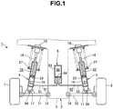
- FIG. 1 shows the hydraulic shock absorbing apparatus when viewed from the rear side of the vehicle body.
- Fig. 2 is a plan view showing the vehicle body when viewed from above, and shows the hydraulic shock absorbing apparatus when viewed from the rear side of the vehicle body for the sake of convenience.
- the hydraulic shock absorbing apparatus for the vehicle according to this embodiment is descried in claims 1, 5, and 6.
- a hydraulic shock absorbing apparatus 1 for a vehicle shown in Fig. 1 is used for an automobile 2 (see Fig. 2 ), and includes a pair of hydraulic shock absorbers 4 and 5 paired in the right-and-left direction of a vehicle body 3, and a reserve tank 6 connected to the hydraulic shock absorbers 4 and 5.
- the automobile 2 indicates a four-wheel vehicle having a left-and-right pair of front wheels 7 and 8 and a left-and-right pair of rear wheels 9 and 10.
- the four-wheel vehicle is not limited to the automobile, and includes any types of four-wheel vehicles such as a saddle type ATV (All Terrain Vehicle) and an open type vehicle like a golf cart.
- These wheels 7 to 10 rotate on a road surface while supporting the vehicle weight, thereby traveling.
- the body left-side front wheel 7 and rear wheel 9 serve as the "first traveling members" of the present invention
- the body right-side front wheel 8 and rear wheel 10 on the body right side serve as the "second traveling members" of the present invention.
- the hydraulic shock absorber 4 or 5 is provided for each of the four wheels. That is, the automobile 2 according to this embodiment includes the left-and-right pair of hydraulic shock absorbers 4 and 5 and the reserve tank 6 for each of a body front portion and a body rear portion.
- Fig. 1 shows the hydraulic shock absorbers 4 and 5 and reserve tank 6 in the body front portion when viewed from the rear side of the vehicle body 3.
- the hydraulic shock absorber 4 located on the body left side is provided between the upper left portion of the vehicle body 3 and a left arm 11 provided in the lower left portion of the vehicle body 3.
- the hydraulic shock absorber 5 located on the body right side is provided between the upper right portion of the vehicle body 3 and a right arm 12 provided in the lower right portion of the vehicle body 3.
- the left arm 11 is swingably connected to the lower left portion of the vehicle body 3 via a connecting shaft 13, and extends from the connecting portion toward the left side of the vehicle body 3.
- the right arm 12 is swingably connected to the lower right portion of the vehicle body 3 via a connecting shaft 14, and extends from the connecting portion toward the right side of the vehicle body 3.
- the axes of the connecting shafts 13 and 14 are parallel to the back-and-forth direction of the vehicle body 3.
- the body left-side front wheel 7 or rear wheel 9 is rotatably provided in the swing end portion of the left arm 11.
- the body right-side front wheel 8 or rear wheel 10 is rotatably provided in the swing end portion of the right arm 12. That is, the left arm 11 connects the body left-side front wheel 7 or rear wheel 9 to be movable in the vertical direction with respect to the vehicle body 3.
- the right arm 12 connects the front wheel 8 or rear wheel 10 on the body right side to be movable in the vertical direction with respect to the vehicle body 3.
- the left arm 11 forms the "first connecting member” of the present invention
- the right arm 12 forms the "second connecting member” of the present invention.
- Each of the hydraulic shock absorbers 4 and 5 is formed by a hydraulic cylinder including a cylinder main body 15 and a piston rod 16. One end portion of each of the hydraulic shock absorbers 4 and 5 is formed by the cylinder main body 15 and the other end portion is formed by the piston rod 16.
- the cylinder main body 15 is swingably connected to the left arm 11 or the right arm 12 via a wheel-side connecting member 17.
- the piston rod 16 is mounted on the upper left or right portion of the vehicle body 3 via a body-side connecting member 18.
- the piston rod 16 is connected to a piston 23 which partitions the interior of the cylinder main body 15 into a first oil chamber 21 and a second oil chamber 22.
- the first oil chamber 21 is formed at one end of the cylinder main body 15 connected to the left arm 11 or the right arm 12.
- the second oil chamber 22 is formed at the other end of the cylinder main body 15 through which the piston rod 16 extends.
- the cylinder main body 15 includes a cylinder 24 extending in the vertical direction in Fig. 3 , a support member 25 which blocks one end portion of the cylinder 24 in a state in which the piston rod 16 extends through, and a lid member 26 which blocks the other end portion of the cylinder 24.
- a spring receiving member 28 which supports the lower end portion of a shock absorbing spring 27 (see Fig. 1 ) is mounted on the outer circumferential portion of the cylinder 24.
- the shock absorbing spring 27 is mounted while being compressed between the spring receiving member 28 and the body-side connecting member 18. Note that the shock absorbing spring 27 may be provided separately from the hydraulic shock absorber 4 or 5.
- the support member 25 is formed in a ring shape, and fitted in the inner circumferential portion of the cylinder 24 in a state in which the piston rod 16 extends through a hollow portion.
- the support member 25 is fixed, by a circlip 29 fixed to the inner circumferential portion of the cylinder 24 and a cap 30 abutting against the outer end face of the cylinder 24, in a state in which it cannot move with respect to the cylinder 24.
- the cap 30 is mounted on the support member 25 by a fixing bolt (not shown).
- An O-ring 31 for sealing a portion with respect to the cylinder 24 is mounted on the outer circumferential portion of the support member 25.
- a plurality of members are mounted on the inner circumferential portion of the support member 25 in line in the axial direction.
- the plurality of members include a dust seal 32, a bearing 33, an oil seal 34, a washer 35, and stopper rubber 36 from above in Fig. 3 .
- the dust seal 32 prevents a foreign substance such as dust or water from entering the cylinder 24 through a gap between the support member 25 and the piston rod 16.
- the bearing 33 slidably supports the piston rod 16, and is press-fitted in the support member 25. That is, the piston rod 16 is movably supported by the support member 25 via the bearing 33.
- the oil seal 34 prevents the hydraulic oil in the cylinder 24 (second oil chamber 22) from leaking outside through the gap between the support member 25 and the piston rod 16.
- the washer 35 supports the stopper rubber 36.
- the stopper rubber 36 reduces a shock when the hydraulic shock absorber 4 or 5 expands most. When the hydraulic shock absorber 4 or 5 expands most, a plate 37 mounted on one end portion of the piston rod 16 abuts against the stopper rubber 36.
- the lid member 26 includes a lid main body 38 fitted in the other end portion of the cylinder 24, and a U-shaped mounting plate 39 provided at the lower end of the lid main body 38.
- the lid main body 38 is fixed to the cylinder 24 by a screw or welding.
- the fitting portion of the lid main body 38 and cylinder 24 adopts an arrangement which prevents the hydraulic oil from leaking.
- a concave portion 40 is formed in a portion of the lid main body 38 which is inserted into the cylinder 24. This concave portion 40 is open in the cylinder 24, and forms part of the first oil chamber 21.
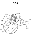
- a shock absorber-side splicing fitting 55 of a first oil hose 51 or a second oil hose 52 is mounted, by a passage forming bolt 56, on a portion of the lid main body 38 which is exposed outside the cylinder 24.
- Each of the first oil hose 51 and the second oil hose 52 makes the first oil chamber 21 in the cylinder main body 15 communicate with a third oil chamber 57 (see Fig. 6 ) of the reserve tank 6 (to be described later).
- the first oil hose 51 connects the reserve tank 6 and the hydraulic shock absorber 4 located on the body left side.
- the hydraulic shock absorber 4 for the left front wheel and the body front-side reserve tank 6 are connected by the first oil hose 51.
- the hydraulic shock absorber 4 for the left rear wheel and the body rear-side reserve tank 6 are connected by the first oil hose 51.
- the second oil hose 52 connects the reserve tank 6 and the hydraulic shock absorber 5 located on the body right side.
- the hydraulic shock absorber 5 for the right front wheel and the body front-side reserve tank 6 are connected by the second oil hose 52.
- the hydraulic shock absorber 5 for the right rear wheel and the body rear-side reserve tank 6 are connected by the second oil hose 52.
- each of the first and second oil hoses 51 and 52 is formed by a hose main body 58, the shock absorber-side splicing fitting 55, and a reserve tank-side splicing fitting 59 (see Fig. 6 ).
- the hose main body 58 is formed by flexible rubber.
- the shock absorber-side splicing fitting 55 is mounted on the hydraulic shock absorber-side end portion of the hose main body 58.
- the reserve tank-side splicing fitting 59 is provided in the reserve tank-side end portion of the hose main body 58.
- the shock absorber-side splicing fitting 55 is formed by a pipe 55a secured to the hose main body 58, and an annular member 55b mounted at the distal end of the pipe 55a.
- the passage forming bolt 56 is extended through the hollow portion of the annular member 55b.
- An oil hole 56a is formed in the passage forming bolt 56.
- the oil hole 56a is connected to a first hydraulic oil passage 61 (see Fig. 6 ) in the first oil hose 51 and a second hydraulic oil passage 62 in the second oil hose 52 via an oil passage 60 formed in the pipe 55a and the annular member 55b.
- the passage forming bolt 56 is threadably engaged with a screw hole 38a of the lid main body 38 in a state in which the oil hole 56a communicates with the concave portion 40 in the lid main body 38, thereby fixing the annular member 55b to the lid member 26.
- a through hole 63 is formed in the U-shaped mounting plate 39 of the lid member 26.
- a connecting shaft 64 (see Fig. 1 ) of the wheel-side connecting member 17 is extended through the through hole 63.
- the wheel-side connecting member 17 has a structure in which the connecting shaft 64 and the left arm 11 or the right arm 12 are connected by shock absorbing rubber.
- the piston rod 16 of the hydraulic shock absorber 4 or 5 is formed by one rod body. As shown in Fig. 3 , in the upper end portion of the piston rod 16 on the opposite side of the cylinder main body 15, a male screw 65 is formed and an adapter 66 is provided. The male screw 65 is formed to mount the body-side connecting member 18 on the piston rod 16. Although not shown in detail, the body-side connecting member 18 has a structure in which the upper end portion of the piston rod 16 and the left or right upper portion of the vehicle body 3 are connected by shock absorbing rubber.
- a male screw 67 and a step portion 68 are formed to mount the piston 23.
- the piston 23 is formed by a piston main body 71 formed in a ring shape, a ring-shaped bearing 72 and an O-ring 73 which are provided in the outer circumferential portion of the piston main body 71, and the like.
- the bearing 72 smoothens sliding between the piston main body 71 and the cylinder 24 of the cylinder main body 15.
- the O-ring 73 seals a portion between the inner circumferential surface of the bearing 72 and the piston main body 71 and widens the bearing 72 outward in the radial direction.
- a through hole 71a in which the piston rod 16 is fitted, and a plurality of oil holes (to be described later) are formed.
- the through hole 71a is located in the axial portion of the piston main body 71.
- the plurality of oil holes include a contraction-side oil hole 71b extending through the left side of the piston main body 71 in Fig. 5 in the axial direction, and an expansion-side oil hole 71c extending through the right side of the piston main body 71 in Fig. 5 in the axial direction.
- a plurality of contraction-side oil holes 71b and a plurality of expansion-side oil holes 71c are alternately provided at an appropriate interval in the circumferential direction of the piston main body 71.
- One end portion (the end portion on the side of the first oil chamber 21) of the contraction-side oil hole 71b is open to the first oil chamber 21.
- One end portion (the end portion on the side of the second oil chamber 22) of the expansion-side oil hole 71c is open to the second oil chamber 22.
- the piston main body 71 is sandwiched and fixed between the step portion 68 of the piston rod 16 and a fixing nut 74 threadably engaged with the male screw 67 in the lower end portion of the piston rod 16 together with a plurality of members (to be described later).
- a ring-shaped plate 75 and a plurality of disk-shaped first leaf springs 76 are sandwiched between the piston main body 71 and the step portion 68.
- a plurality of disk-shaped second leaf springs 77, a shim 78, and a washer 79 are sandwiched between the piston main body 71 and the fixing nut 74.
- the first leaf springs 76 close an opening on the side of the second oil chamber 22 in the contraction-side oil hole 71b formed in the piston main body 71.
- the first leaf springs 76 form a check valve 80 which permits the hydraulic oil to flow through the contraction-side oil hole 71b from the side of the first oil chamber 21 to the side of the second oil chamber 22.
- the second leaf springs 77 close an opening on the side of the first oil chamber 21 in the expansion-side oil hole 71c.
- the second leaf springs 77 form a check valve 81 which permits the hydraulic oil to flow through the expansion-side oil hole 71c from the side of the second oil chamber 22 to the side of the first oil chamber 21.
- the contraction-side oil hole 71b, the expansion-side oil hole 71c, and the first and second leaf springs 76 and 77 form a "throttle" in an invention described in claim 1.
- the reserve tank 6 includes a base member 82, a cylinder 83 having a cylindrical shape with a closed end, and a free piston 84.
- the reserve tank-side splicing fittings 59 of the first and second oil hoses 51 and 52 are mounted on the base member 82.
- the cylinder 83 is supported by the base member 82.
- the free piston 84 is provided in the cylinder 83.
- the reserve tank 6 according to this embodiment is arranged at the center of the vehicle body 3 in the right-and-left direction.
- the base member 82 is formed by a plate-like portion 82a on which the two reserve tank-side splicing fittings 59 are mounted, and a columnar portion 82b connected to the cylinder 83.
- Two through holes 85 are formed in the plate-like portion 82a. Fixing bolts (not shown) for fixing the reserve tank 6 to the vehicle body 3 are inserted into the through holes 85.
- the first oil hose 51 is connected to a splicing fitting 59L located on the left side in Fig. 6 out of the two splicing fittings 59.
- the second oil hose 52 is connected to a splicing fitting 59R located on the right side.
- Each of the splicing fittings 59L and 59R is formed by a nipple 87 threadably engaged with a screw hole 86 of the base member 82, and a nut member 88 with the pipe 55a secured to the hose main body 58.
- the screw hole 86 extends through the plate-like portion 82a of the base member 82, and makes the interior and exterior of the columnar portion 82b communicate with each other.
- An O-ring 89 for sealing is mounted between the nipple 87 and an open end portion outside the screw hole 86.
- the nipple 87 is formed in a columnar shape with an through hole 87a.
- a male screw 87b is formed in the distal end portion of the nipple 87.
- the nut member 88 is threadably engaged with the male screw 87b of the nipple 87.
- the first and second hydraulic oil passages 61 and 62 in the columnar portion 82b and hose main bodies 58 communicate with each other via the splicing fittings 59L and 59R.
- the columnar portion 82b of the base member 82 includes a large-diameter portion 91 fitted in the opening of the cylinder 83, and a small-diameter portion 92 connecting the large-diameter portion 91 and the plate-like portion 82a.
- An O-ring 93 for sealing a portion with respect to the cylinder 83 is mounted on the large-diameter portion 91.
- a space inside the columnar portion 82b is open to the interior of the cylinder 83.
- a circlip 94 which regulates the protrusion of the base member 82 outside the free piston 84 is mounted in the opening of the cylinder 83.
- a plug member 95 is provided in the bottom portion of the cylinder 83. The plug member 95 is used to insert a gas injection needle (not shown) when injecting N 2 gas into the cylinder.
- the free piston 84 provided in the cylinder 83 is movably fitted on the inner circumferential surface of the cylinder 83.
- the free piston 84 partitions the interior of the cylinder 83 into the third oil chamber 57 on the side of the base member 82 and a gas chamber 96 on the opposite side.
- the gas chamber 96 is filled with N 2 gas of a predetermined pressure.
- the free piston 84 is formed by a disk-shaped piston main body 84a, a ring-shaped bearing 97 and first O-ring 98 provided in the outer circumferential portion of the piston main body 84a, and a second O-ring 99 provided between the inner circumferential surface of the bearing 97 and the piston main body 71.
- the bearing 97 smoothens sliding between the piston main body 71 and the cylinder 83.
- the first O-ring 98 seals a portion between the piston main body 71 and the cylinder 83.
- the second O-ring 99 seals a portion between the inner circumferential surface of the bearing 97 and the piston main body 71, and also widens the bearing 97 outward in the radial direction.
- the third oil chamber 57 is formed by a space in the cylinder 83 located on the opening side with respect to the free piston 84, and a space in the columnar portion 82b.
- the third oil chamber 57 is filled with the hydraulic oil.
- the free piston 84 forms part of the wall of the third oil chamber 57, and moves in a direction away from the base member 82 when the hydraulic oil is sent from the first oil hose 51 or the second oil hose 52 to the third oil chamber 57 against the pressure of the gas in the gas chamber 96.
- the free piston 84 moves in a direction closer to the base member 82.
- the first oil hose 51 connected to the reserve tank 6 connects the first oil chamber 21 of the hydraulic shock absorber 4 located on the body left side and the third oil chamber 57 of the reserve tank 6.
- the second oil hose 52 connects the first oil chamber 21 of the hydraulic shock absorber 5 located on the body right side and the third oil chamber 57 of the reserve tank 6.
- the interior of each of the first oil hose 51 and the second oil hose 52 is filled with the hydraulic oil.
- the first hydraulic oil passage 61 in the first oil hose 51 and the second hydraulic oil passage 62 in the second oil hose 52 are individually connected to the third oil chamber 57. As shown in Fig. 6 , the first hydraulic oil passage 61 and the second hydraulic oil passage 62 are connected to the third oil chamber 57 in a state in which they extend in parallel with each other. An opening of each of the first and second hydraulic oil passages 61 and 62, which serves as a boundary with the third oil chamber 57, is directed to the free piston 84.
- the vehicle body 3 including the hydraulic shock absorbing apparatus 1 for the vehicle with the above arrangement for example, when a handle operation in the right direction is performed during traveling, the vehicle body 3 is to roll to the left side, as shown in Fig. 7 .
- the pair of hydraulic shock absorbers 4 and 5 are to operate in the opposite directions.
- the hydraulic oil is pushed out from the contracting body left-side hydraulic shock absorber 4.
- the free piston 84 in the reserve tank 6 is pressed by the hydraulic oil to move toward the gas chamber 96.
- the first hydraulic oil passage 61 and the second hydraulic oil passage 62 are individually connected to the third oil chamber 57, and the whole pushed out amount of the hydraulic oil flows into the third oil chamber 57 via the individual hydraulic oil passage 61 or 62.
- the free piston 84 in the reserve tank 6 is pressed by the hydraulic oil to move toward the gas chamber 96. Therefore, unlike patent literature 2, it is possible to suppress a change in attitude of the vehicle body 3 by the hydraulic oil instantaneously flowing into the other hydraulic shock absorber without increasing the inclination of the vehicle body.
- the magnitude of the oil pressure which presses the free piston 84 corresponds to the change speed and change amount of the attitude of the vehicle body 3. If the attitude of the vehicle body 3 rapidly changes, the free piston 84 is pressed by a large oil pressure to move at high speed. In this case, it can be expected that the hydraulic oil is sucked into the reserve tank 6 from the side of the other hydraulic shock absorber (hydraulic shock absorber 5), and the oil pressure acts on the other hydraulic shock absorber in the contracting direction. If the oil pressure acts on the other hydraulic shock absorber in the contracting direction, it is possible to further suppress a change in attitude of the vehicle body 3.
- the hydraulic oil flowing into the reserve tank 6 receives a gas reaction force, and is pushed out toward the other hydraulic shock absorber.
- the hydraulic shock absorber expands. Since, however, the time required from the start to the end of a change in attitude of the vehicle body 3 is short, the change in attitude ends before the other hydraulic shock absorber expands, and thus there is no problem.
- the reserve tank 6 is formed using the free piston 84 having a simple shape, and has a simple structure.
- the hydraulic shock absorbing apparatus for the vehicle which can suppress a change in attitude of the vehicle body 3 without increasing the inclination of the vehicle body 3 at the time of rolling in which the pair of hydraulic shock absorbers 4 and 5 operate in the opposite directions while adopting an arrangement that can be readily manufactured.
- the reserve tank 6 is arranged at the center of the vehicle body 3 in the right-and-left direction.
- a gas pressure acting on the body left-side hydraulic shock absorber 4 via the hydraulic oil and a gas pressure acting on the body right-side hydraulic shock absorber 5 via the hydraulic oil can be equalized. Therefore, by incorporating the hydraulic shock absorbing apparatus 1, the riding comfort of the vehicle is further improved.
- the vehicle according to this embodiment is a four-wheel vehicle having the left-and-right pair of front wheels 7 and 8 and the left-and-right pair of rear wheels 9 and 10.
- the first traveling members correspond to the front wheel 7 and rear wheel 9 located on the body left side
- the second traveling members correspond to the front wheel 8 and rear wheel 10 on the body right side.
- the pair of hydraulic shock absorbers 4 and 5 of the present invention are provided on each of the body front and rear sides.
- the pair of hydraulic shock absorbers 4 and 5 located on the body front side are provided between the vehicle body 3 and the left arm 11 and right arm 12 for the front wheels (the first and second connecting portions located on the body front side).
- the pair of hydraulic shock absorbers 4 and 5 located on the body rear side are provided between the vehicle body 3 and the left arm 11 and right arm 12 for the rear wheels (the first and second connecting portions located on the body rear side).
- the hydraulic shock absorbing apparatus for the vehicle according to the present invention can be arranged, as shown in Figs. 8 to 10 .
- a hydraulic shock absorbing apparatus for the vehicle shown in each of Figs. 8 and 9 is an example of a hydraulic shock absorbing apparatus described in claim 6.
- a hydraulic shock absorbing apparatus 1 for a vehicle shown in Fig. 8 is formed by a hydraulic shock absorber 4 for a left front wheel, a hydraulic shock absorber 5 for a right front wheel, and a reserve tank 6 connected to the hydraulic shock absorbers 4 and 5. Hydraulic shock absorbers for rear wheels are not shown but individual hydraulic shock absorbers which are not connected to other hydraulic shock absorbers are used.
- a hydraulic shock absorbing apparatus 1 shown in Fig. 9 is formed by a hydraulic shock absorber 4 for a left rear wheel, a hydraulic shock absorber 5 for a right rear wheel, and a reserve tank 6 connected to the hydraulic shock absorbers 4 and 5. Hydraulic shock absorbers for front wheels are not shown but individual hydraulic shock absorbers which are not connected to other hydraulic shock absorbers are used.
- a hydraulic shock absorbing apparatus for a vehicle shown in Fig. 10 is an example of a hydraulic shock absorbing apparatus described in claim 7.
- the first pair of first and second traveling members are a pair of traveling members formed from a body left-side front wheel 7 and a body right-side rear wheel 10.
- the second pair of first and second traveling members are a pair of traveling members formed from a body right-side front wheel 8 and a body left-side rear wheel 9.
- the first pair of hydraulic shock absorbers include a hydraulic shock absorber 4 for the body left-side front wheel 7 and a hydraulic shock absorber 5 for the body right-side rear wheel 10.
- the second pair of hydraulic shock absorbers include a hydraulic shock absorber 5 for the body right-side front wheel 8 and a hydraulic shock absorber 4 for the body left-side rear wheel 9. Therefore, the hydraulic shock absorber 4 for the left front wheel 7 is connected to one reserve tank 6 via a first oil hose 51 (first hydraulic oil passage 61).
- the hydraulic shock absorber 5 for the right rear wheel 10 is connected to the reserve tank 6 via a second oil hose 52 (second hydraulic oil passage 62).
- hydraulic shock absorber 5 for the right front wheel 8 is connected to another reserve tank 6 via a first oil hose 51 (first hydraulic oil passage 61).
- the hydraulic shock absorber 4 for the left rear wheel 9 is connected to the other reserve tank 6 via a second oil hose 52 (second hydraulic oil passage 62).
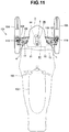
- the hydraulic shock absorbing apparatus for the vehicle according to the present invention is applicable to the body front-side suspension of a snowmobile, as shown in Fig. 11 .
- the same reference numerals as those of the members described with reference to Figs. 1 to 10 denote the same or similar members in Fig. 11 , and a detailed description thereof will appropriately be omitted.
- a hydraulic shock absorbing apparatus for a vehicle according to this embodiment corresponds to a hydraulic shock absorbing apparatus described in claim 8.
- An occupant sits astride a seat 102, and drives a snowmobile 101 shown in Fig. 11 by grasping a handle bar 103.
- the vehicle weight of the body front portion of the snowmobile 101 is supported by a body left-side steering ski 104 and a body right-side steering ski 105.
- steering skis 104 and 105 are connected to the vehicle body 3 via suspensions with a left-and-right pair of lower arms 106 and 107 and a left-and-right pair of upper arms 108 and 109 to be movable in the vertical direction.
- the steering skis 104 and 105 are steered in the left or right direction when the handle bar 103 is operated in the left or right direction.
- the body left-side steering ski 104 corresponds to the "first traveling member" of the present invention
- the body right-side steering ski 105 corresponds to the "second traveling member" of the present invention.
- a body left-side hydraulic shock absorber 4 is provided between the swing end portion of the body left-side lower arm 106 and the left upper portion of a vehicle body 3.
- a body right-side hydraulic shock absorber 5 is provided between the swing end portion of the body right-side lower arm 107 and the right upper portion of the vehicle body 3.
- the body left-side lower arm 106 corresponds to the "first connecting member" of the present invention
- the body right-side lower arm 107 corresponds to the "second connecting member" of the present invention.
- each of the hydraulic shock absorbers 4 and 5 a cylinder main body 15 is connected to the vehicle body 3, unlike the first embodiment.
- each of the hydraulic shock absorbers 4 and 5 contracts or expands when the vehicle body 3 rolls.
- a shock absorbing spring is provided between the cylinder main body 15 of each of the hydraulic shock absorbers 4 and 5 and a bracket 110 on the side of a corresponding one of the lower arms 106 and 107.
- the first oil chamber (not shown) of the body left-side hydraulic shock absorber 4 is connected to a third oil chamber 57 of a reserve tank 6 via a first oil hose 51.
- the first oil chamber (not shown) of the body right-side hydraulic shock absorber 5 is connected to the third oil chamber 57 of the reserve tank 6 via a second oil hose 52.
- the hydraulic shock absorbers 4 and 5 and the reserve tank 6 are the same as those used when adopting the first embodiment.
- the reserve tank 6 according to this embodiment is also arranged at the center of the vehicle body 3 in the right-and-left direction.
- the reserve tank 6 is arranged at the center of the vehicle body 3 in the right-and-left direction.
- a gas pressure acting on the body left-side hydraulic shock absorber 4 via the hydraulic oil and a gas pressure acting on the body right-side hydraulic shock absorber 5 via the hydraulic oil can be equalized. Consequently, by incorporating this hydraulic shock absorbing apparatus, the riding comfort of the snowmobile 101 is further improved.
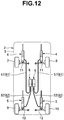
- the hydraulic shock absorbing apparatus for the vehicle according to the present invention can be arranged, as shown in Fig. 12 .
- the same reference numerals as those of the members described with reference to Figs. 1 to 11 denote the same or similar members in Fig. 12 , and a detailed description thereof will appropriately be omitted.
- a hydraulic shock absorbing apparatus for a vehicle shown in Fig. 12 is an example of a hydraulic shock absorbing apparatus described in claim 9.
- the vehicle according to this embodiment is a four-wheel vehicle having a left-and-right pair of front wheels 7 and 8 and a left-and-right pair of rear wheels 9 and 10.
- pairs of first and second traveling members include a pair of traveling members formed from the body-left side front wheel 7 and rear wheel 9, and a pair of traveling members formed from the body right-side front wheel 8 and rear wheel 10.
- pairs of first and second connecting members according to this embodiment include two left arms 11 and 12 paired in the back-and-forth direction of a vehicle body 3 on the body left side and two right arms 11 and 12 paired in the back-and-forth direction of the vehicle body 3 on the body right side.
- the first pair of hydraulic shock absorbers are formed by a hydraulic shock absorber 4 for the body left-side front wheel 7 and a hydraulic shock absorber 5 for the body left-side rear wheel 9.
- the second pair of hydraulic shock absorbers are formed by a hydraulic shock absorber 4 for the body right-side front wheel 8 and a hydraulic shock absorber 5 for the body right-side rear wheel 10.
- the hydraulic shock absorber 4 for the body left-side front wheel 7 is connected to one reserve tank 6 via a first oil hose 51 (first hydraulic oil passage 61).
- the hydraulic shock absorber 5 for the body left-side rear wheel 9 is also connected to the reserve tank 6 via a second oil hose 52 (second hydraulic oil passage 62).
- the hydraulic shock absorber 4 for the body right-side front wheel 8 is connected to another reserve tank 6 via a first oil hose 51 (first hydraulic oil passage 61).
- the hydraulic shock absorber 5 for the body right-side rear wheel 10 is connected to the other reserve tank 6 via a second oil hose 52 (second hydraulic oil passage 62).
- a change in attitude of the vehicle body 3 is suppressed when pitching occurs in which the front and rear portions of the vehicle body 3 are displaced in the vertically opposite directions.
- the whole amount of the hydraulic oil pushed out from the contracting body front-side hydraulic shock absorber flows into a third oil chamber 57 via the individual first hydraulic oil passage 61 or 62, a free piston 84 in the reserve tank 6 is pressed by the hydraulic oil to move toward a gas chamber 96. Therefore, unlike patent literature 2, it is possible to suppress a change in attitude of the vehicle body 3 by the hydraulic oil instantaneously flowing into the other hydraulic shock absorber without increasing the inclination of the vehicle body.
- the hydraulic oil flowing into the reserve tank 6 receives a gas reaction force, and is pushed out toward the other hydraulic shock absorber.
- the hydraulic shock absorber expands. Since, however, the time required from the start to the end of a change in attitude of the vehicle body 3 is short, the change in attitude ends before the other hydraulic shock absorber expands, and thus there is no problem.
- the hydraulic shock absorbing apparatus for the vehicle according to the present invention is applicable to the body rear-side suspension of a snowmobile, as shown in Fig. 13 .
- the same reference numerals as those of the members described with reference to Figs. 1 to 12 denote the same or similar members in Fig. 13 , and a detailed description thereof will appropriately be omitted.
- a hydraulic shock absorbing apparatus for a vehicle according to this embodiment corresponds to a hydraulic shock absorbing apparatus described in claim 10.
- the vehicle according to this embodiment is a snowmobile 101 shown in Fig. 13 .
- a driving device 121 shown in Fig. 13 is provided in the rear portion of a vehicle body 3 of the snowmobile 101.
- the driving device 121 has a structure for driving one driving track belt 122 to rotate.
- the driving device 121 according to this embodiment includes a plurality of wheels 123 to 125 and a plurality of guide pulleys 126 to 128 to which the track belt 122 is spliced, and a slide rail 131 arranged on the inner surface of the lower portion of the track belt 122.
- the driving wheel 123 located at a position closest to the body front side (the left side in Fig. 13 ) is driven by an engine (not shown) to rotate.
- the driving wheel 123 and the upper guide wheel 124 and lower guide wheel 125 located on the body rear side are provided on each of the left and right sides of the vehicle body 3.
- the driving wheel 123 is rotatably supported by a vehicle body frame 132 provided in the vehicle body 3 of the snowmobile 101 in a state in which the movement in the vertical, back-and-forth, and right-and-left directions is regulated.
- the upper guide wheel 124 is rotatably supported by the vehicle body frame 132 via an upper wheel shaft 133 extending in the right-and-left direction of the vehicle body 3 in a state in which the movement in the vertical, back-and-forth, and right-and-left directions is regulated.
- the lower guide wheel 125 is rotatably supported by the rear end portion of the slide rail 131 (to be described later) via a lower wheel shaft 134 extending in the right-and-left direction of the vehicle body.
- the plurality of guide pulleys 126 to 128 are respectively, rotatably supported by the slide rail 131 (to be described later).
- the slide rail 131 guides the track belt 122 while pressing the track belt 122 against a snow surface.
- the slide rail 131 according to this embodiment is formed, in a ladder shape when viewed from above, by a left-and-right pair of side rails 141 (one of them is not shown), a plurality of shafts connecting the side rails 141 at a plurality of positions in the back-and-forth direction, and the like.
- the plurality of shafts are cross shafts 142 to 144, a lower arm shaft 145, and the lower wheel shaft 134.
- the front portion of the slide rail 131 is connected to the vehicle body frame 132 via a body front-side arm 146 to be movable in the vertical direction.
- the rear portion of the slide rail 131 is connected to the vehicle body frame 132 via a body rear-side arm 147 to be movable in the vertical direction. Since, therefore, part of the vehicle weight acts on the slide rail 131, the track belt 122 travels while supporting the vehicle weight by rotation.
- the body front-side arm 146 and the body rear-side arm 147 are inclined in a state in which the body front side is higher than the body rear side when viewed from the side. Furthermore, the left-and-right pair of body front-side arms 146 and the left-and-right pair of body rear-side arms 147 are provided in the vehicle body.
- the front end portions of the left-and-right pair of body front-side arms 146 are respectively connected to an upper arm shaft 148 extending in the right-and-left direction, and is pivotably connected to the vehicle body frame 132 via the upper arm shaft 148.
- a bracket 149 is secured to the central portion of the upper arm shaft 148 in the axial direction, and the upper end portion of the body front-side hydraulic shock absorber 4 is pivotably connected to the central portion via the bracket 149.
- the lower end portion of the body front-side hydraulic shock absorber 4 is pivotably connected to one end portion of a first link 151 pivotably supported by the central cross shaft 143. That is, the body front-side hydraulic shock absorber 4 is substantially provided between the vehicle body frame 132 and the central cross shaft 143 of the slide rail 131.
- the body front-side hydraulic shock absorber 4 is provided between the vehicle body frame 132 and the slide rail 131 in a state in which a cylinder main body 15 is located under the hydraulic shock absorber 4 and a piston rod 16 is located above the hydraulic shock absorber 4. Furthermore, a shock absorbing spring 27 is provided between the upper and lower end portions of the body front-side hydraulic shock absorber 4.
- the lower arm shaft 145 extending in the right-and-left direction is integrally formed in the rear end portion of the body front-side arm 146.
- the rear end portion of the body front-side arm 146 is pivotably connected to the side rail 141 via the lower arm shaft 145.
- a second link 152 is secured to the central portion of the lower arm shaft 145 in the axial direction.
- a third link 153 is pivotably connected to the second link 152.
- the central portion of the lower arm shaft 145 in the axial direction is connected to the lower end portion of a body rear-side hydraulic shock absorber 5 (to be described later) via the third link 153.
- the lower end portion of the hydraulic shock absorber 5 is pivotably connected to the third link 153.
- the other end portion of the above-described first link 151 is pivotably connected to the third link 153.
- the front end portions of the left-and-right pair of body rear-side arms 147 are respectively, pivotably connected to the above-described upper wheel shaft 133.
- the rear end portions of the body rear-side arms 147 are respectively, pivotably connected to the side rails 141 via fourth links 154.
- a support bracket 155 extending upward is provided in each of the body rear-side arms 147.
- the upper end portion of the body rear-side hydraulic shock absorber 5 is pivotably connected to the upper end portion of the support bracket 155.
- the body rear-side hydraulic shock absorber 5 is substantially provided between the vehicle body frame 132 and the lower arm shaft 145 of the slide rail 131.
- the lower arm shaft 145 is located on the body rear side of the above-described central cross shaft 143.
- the pair of hydraulic shock absorbers 4 and 5 according to this embodiment are respectively suspended between the vehicle body frame 132 and two positions of the slide rail 131 in the back-and-forth direction.
- a torsion spring 156 is arranged near the body rear-side hydraulic shock absorber 5.
- the torsion spring 156 is disposed between the vehicle body frame 132 and the left and right side rails 141, and biases the slide rail 131 in a direction away from the vehicle body frame 132.
- the first oil chamber (not shown) of the body front-side hydraulic shock absorber 4 is connected to a third oil chamber 57 of a reserve tank 6 via a first oil hose 51.
- the first oil chamber (not shown) of the body rear-side hydraulic shock absorber 5 is connected to the third oil chamber 57 of the reserve tank 6 via a second oil hose 52.
- the hydraulic shock absorbers 4 and 5 and the reserve tank 6 are the same as those used when adopting the first embodiment.
- the reserve tank 6 according to this embodiment is arranged at a position surrounded by the track belt 122, and supported by the vehicle body frame 132 via a bracket (not shown).
- the body front-side arm 146 swings about the upper arm shaft 148 and the body rear-side arm 147 swings about the upper wheel shaft 133.
- the pair of hydraulic shock absorbers 4 and 5 operate in the same direction or opposite directions along with the swing. If the snowmobile 101 pitches, the body front-side hydraulic shock absorber 4 and the body rear-side hydraulic shock absorber 5 operate in the opposite directions, thereby suppressing a change in attitude of the vehicle body by a simple structure, similarly to the embodiment shown in Fig. 12 .
- the hydraulic shock absorbing apparatus for the vehicle according to the present invention can be arranged, as shown in Figs. 14 to 17 .
- the same reference numerals as those of the members described with reference to Figs. 1 to 11 denote the same or similar members in Figs. 14 to 17 , and a detailed description thereof will be omitted.
- a hydraulic shock absorbing apparatus for a vehicle according to this embodiment corresponds to a hydraulic shock absorbing apparatus described in claims 2, 3, 11, and 12.
- a hydraulic shock absorbing apparatus 1 shown in Fig. 14 is mounted on a four-wheel-drive vehicle (not shown) which runs a rocky tract or a bad road, or a snowmobile 101 shown in Fig. 11 or 13 .
- Fig. 14 shows the hydraulic shock absorbing apparatus 1 in a form in which it is mounted on the snowmobile 101. That is, cylinder main bodies 15 of hydraulic shock absorbers 4 and 5 are located at upper positions and piston rods 16 project downward from the cylinder main bodies 15.
- a first oil chamber 21 formed in the body left-side hydraulic shock absorber 4 communicates with a third oil chamber 57 of a reserve tank 6 by a first hydraulic oil passage 201.
- a first oil chamber 21 formed in the body right-side hydraulic shock absorber 5 communicates with the third oil chamber 57 of the reserve tank 6 by a second hydraulic oil passage 202.
- the first and second hydraulic oil passages 201 and 202 can be formed by first and second oil hoses 51 and 52 and splicing fittings 55 and 59, respectively.
- the hydraulic shock absorbing apparatus 1 includes a communication path 203 for making the first hydraulic oil passage 201 and the second hydraulic oil passage 202 communicate with each other, and an on-off valve 204 for opening/closing the communication path 203.
- the communication path 203 makes the intermediate portion of the first hydraulic oil passage 201 and that of the second hydraulic oil passage 202 communicate with each other.
- a base valve 205 is provided in a portion of each of the first hydraulic oil passage 201 and the second hydraulic oil passage 202, which is closer to the third oil chamber 57 of the reserve tank 6 than to the communication path 203.
- the base valve 205 is formed by a variable throttle, and will be described in detail later.
- the communication path 203, the on-off valve 204, and the base valves 205 are provided in a base member 82 of the reserve tank 6, as shown in Fig. 15 .
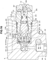
- the communication path 203 is provided near two nipples 87 mounted on the base member 82. That is, the communication path 203 is connected to a screw hole 86 in which the nipple 87 located in the lower left portion in Fig. 16 is screwed, as shown in Fig. 16 , and makes the two screw holes 86 for the nipples communicate with each other, as shown in Fig. 17 .
- One end of the communication path 203 extends through the base member 82 toward one side, and is open to one side surface of the base member 82.
- the on-off valve 204 for opening/closing the communication path 203 is formed by a valve seat 206 including a tapered surface provided in the middle of the communication path 203, and a columnar valve body 207 which comes into contact with and moves apart from the valve seat 206.
- the valve body 207 is threadably engaged with the base member 82 in a threadably engaging portion 208.
- a distal end portion (the right end portion in Fig. 17 ) of the valve body 207 is formed in a shape in which it is fitted and seated on the valve seat 206.
- a hexagonal hole 207a with which a tool (not shown) is engaged is formed in the other end portion of the valve body 207.
- An O-ring 209 for sealing a portion with respect to the base member 82 is mounted on the intermediate portion of the valve body 207.
- the on-off valve 204 is rotated in a direction in which the valve body 207 is screwed in the threadably engaging portion 208, and the distal end portion of the valve body 207 is closed by abutting against the valve seat 206.
- the on-off valve 204 is opened by rotating the valve body 207 in a direction in which the threadably engaging portion 208 is loosened.
- the base valve 205 is mounted in a valve hole 211 of the base member 82.
- the valve hole 211 is a non-through hole open to one side portion of the base member 82, and is formed in a shape extending in a direction orthogonal to an axis C1 of a cylinder 83 of the reserve tank 6.
- a concave portion 212 having a diameter smaller than that on the opening side is formed in the bottom of the valve hole 211.
- the boundary between the concave portion 212 and the opening side is formed by a step 213.
- the concave portion 212 is connected to the screw hole 86 for the nipple by a communicating hole 214.
- the base valve 205 includes a cylindrical valve housing 215 inserted into the valve hole 211, and a valve body 216 threadably engaged with the interior of the hollow portion of the valve housing 215.
- valve housing 215 In the outer circumferential portion of the valve housing 215, a male screw 218 threadably engaged with a female screw 217 formed on the inner wall of the valve hole 211 is formed, and an O-ring 219 for sealing a portion with respect to the hole wall surface of the valve hole 211 is mounted.
- the valve housing 215 is screwed in the valve hole 211 and fixed in a state in which a plurality of members are sandwiched between the valve housing 215 and the step 213 of the valve hole 211.
- the plurality of members located between the valve housing 215 and the step 213 are a first cylindrical member 221 fitted in the step 213, a disk-shaped valve seat member 222 fitted in a cylinder 221a of the first cylindrical member 221, and a second cylindrical member 223 sandwiched between the outer circumferential portion of the valve seat member 222 and the valve housing 215.
- the first cylindrical member 221 is formed by the cylinder 221a fitted in the valve hole 211, and an inner flange 221b along the step 213.
- a plurality of ring-shaped plates 224 having different inner diameters are fitted in the first cylindrical member 221 to be movable in the axial direction. These plates 224 are arrayed so that the plate 224 having a smaller inner diameter is located closer to the bottom of the valve hole 211.
- the valve seat member 222 serves as the valve seat of the base valve 205.
- the valve seat member 222 has a plurality of function units.
- the plurality of function units include a valve seat 231 located in the axial portion of the disk-shaped valve seat member 222, and a bypass passage 232 formed from a plurality of through holes provided in the periphery of the valve seat 231.
- the valve seat 231 includes a first seat surface 231a facing the bottom of the valve hole 211, and a second seat surface 231b directed to the opening side of the valve hole 211. Furthermore, the through hole 233 open to the first seat surface 231a and the second seat surface 231b is formed in the central portion of the valve seat 231.
- the plate 224 having the smallest inner diameter has an inner circumferential portion facing the first seat surface 231a.
- this ring-shaped plate 224 is pressed by the hydraulic oil to abut against the first seat surface 231a, thereby regulating the flow of the hydraulic oil.
- this ring-shaped plate 224 is pressed by the hydraulic oil to move away from the first seat surface 231a, thereby permitting the flow of the hydraulic oil.
- the ring-shaped plate 224 functions as a check valve.
- One end portion of a through hole 233 open to the first seat surface 231a is kept in an open state even in a state in which the ring-shaped plate 224 is in tight contact with the first seat surface 231a. That is, one end portion of the through hole 233 is always open to the bottom portion of the valve hole 211.
- the second cylindrical member 223 is formed in a cylindrical shape.
- One end of the above-described bypass passage 232 is open to a hydraulic oil chamber 234 formed inside the second cylindrical member 223.
- a plurality of notches 223a and a through hole 223b are formed in the second cylindrical member 223 to pass the hydraulic oil in the radial direction.
- the outer diameter of the second cylindrical member 223 is smaller than the inner diameter of the valve hole 211. Therefore, an annular hydraulic oil passage 235 is formed between the second cylindrical member 223 and the hole wall surface of the valve hole 211.
- a communicating hole 236 for making the hydraulic oil passage 235 communicate with the third oil chamber 57 of the reserve tank 6 is open to the hole wall surface of the valve hole 211 on which the hydraulic oil passage 235 is formed. Therefore, the third oil chamber 57 communicates with the hydraulic oil chamber 234 in the second cylindrical member 223 via the communicating hole 236, the annular hydraulic oil passage 235, the notches 223a, and the through hole 223b.
- the valve body 216 is formed in a columnar shape. One end portion of the valve body 216 on the bottom side of the valve hole 211 is formed by a flat end face 216a contacting the second seat surface 231b of the valve seat 231, and a needle 216b projecting from the end face 216a.
- the needle 216b is formed in a conical shape tapering toward the distal end, and inserted into the through hole 233 of the above-described valve seat 231.
- a male screw 242 threadably engaged with a female screw 241 of the valve housing 215, a ball 243, and an O-ring 244 are provided in the outer circumferential portion of the valve body 216.
- the ball 243 is pressed by a compression coil spring 245 accommodated in the valve body 216, and is engaged with concave grooves 246 of the valve housing 215.
- the concave grooves 246 are formed to have serrations in the inner circumferential portion of the valve housing 215. That is, each concave groove 246 is formed in a shape extending in the axial direction of the valve housing 215, and many concave grooves 246 are formed to be arrayed in the circumferential direction of the inner circumferential portion of the valve housing 215. If the valve body 216 rotates about an axis C2, the ball 243 crosses over a projection portion between the concave grooves 246, thereby providing moderation to rotation.
- the O-ring 244 seals a portion between the valve body 216 and the inner circumferential portion of the valve housing 215.
- An operation handle 247 is mounted on the other end portion of the valve body 216 by a mounting screw 248.
- the valve body 216 moves along the axis C2 while rotating in the valve housing 215 by the action of the screw.
- the valve body 216 advances toward the valve seat 231, and the end face 216a of one end portion abuts against the second seat surface 231b, thereby setting the base valve 205 in a full close state.
- valve body 216 retreats from the full close state, a gap is formed between the end face 216a and the second seat surface 231b, and the needle 216b is pulled out from the through hole 233 of the valve seat 231 to open the base valve 205, thereby making the through hole 233 communicate with the hydraulic oil chamber 234 in the second cylindrical member 223.
- the thus opened base valve 205 substantially functions as a variable throttle.
- the valve body 216 can retreat until the male screw 242 or the ball 243 abuts against the valve housing 215 to regulate rotation. In the state in which the valve body 216 retreats in this way, the base valve 205 is set in the full open state.
- the aperture ratio of the valve body 216 can be readily set based on the number of times the ball 243 crosses over the projection portion between the concave grooves 246. The number of times can be readily counted since the resistance when rotating the handle 247 increases/decreases.
- the hydraulic shock absorbing apparatus 1 is used in the state in which the on-off valve 204 is open when a four-wheel-drive vehicle runs a rocky tract or a bad road or a snowmobile runs on fresh snow. If the on-off valve 204 is opened, the first hydraulic oil passage 201 and the second hydraulic oil passage 202 communicate with each other via the communication path 203 and the on-off valve 204, thereby allowing the hydraulic oil to smoothly flow between the body left-side hydraulic shock absorber 4 and the body right-side hydraulic shock absorber 5. That is, the hydraulic oil pushed when one of the hydraulic shock absorbers contracts flows into the other hydraulic shock absorber, and the other hydraulic shock absorber resultantly expands.
- the outer ski in the turning direction gets covered with fresh snow by the centrifugal force, and it may be impossible to correctly change the running direction.
- the occupant shifts the weight by leaning inward in the turning direction.
- the occupant performs a so-called counter steering operation so that the vehicle body inclines inward in the turning direction and the outer ski in the turning direction floats.
- the on-off valve 204 is open, the vehicle body can be readily inclined inward in the turning direction. Therefore, even in a status in which the snowmobile suddenly turns on fresh snow, it can readily run.
- the base valve 205 formed from a throttle is provided in a portion of each of the first and second hydraulic oil passages 201 and 202, which is closer to the third oil chamber 57 than to the communication path 203.
- the flow rate of the hydraulic oil flowing into or out between the third oil chamber 57 and each of the first and second hydraulic oil passages 201 and 202 is regulated by the base valve 205. That is, according to this embodiment, in the state in which the on-off valve 204 is closed, the flow rate of the hydraulic oil flowing into the third oil chamber 57 or flowing out from the third oil chamber 57 can be readily adjusted. Therefore, according to this embodiment, it is possible to provide the hydraulic shock absorbing apparatus for the vehicle capable of adjusting the responsiveness and the like.
- a base valve can be provided in a hydraulic shock absorber, as shown in Fig. 18 .
- a hydraulic shock absorbing apparatus for a vehicle according to this embodiment corresponds to a hydraulic shock absorbing apparatus described in claims 4 and 13.
- a hydraulic shock absorber 4 or 5 shown in Fig. 18 is mounted on an automobile or a snowmobile 101 shown in Fig. 11 or 13 .
- a base valve 205 shown in Fig. 18 is mounted in a valve hole 251 formed in a lid member 26 of the hydraulic shock absorber 4 or 5. That is, the base valve 205 is provided in each of the pair of hydraulic shock absorbers 4 and 5.
- the valve hole 251 is open to one side of the lid member 26 and is connected to a concave portion 40 of the lid member 26.
- One end of a screw hole 38a for mounting a shock absorber-side splicing fitting 55 is open to the hole wall surface of the valve hole 251 corresponding to an annular hydraulic oil passage 235 of the base valve 205.
- a first oil chamber 21 of the hydraulic shock absorber 4 or 5 and the first or second hydraulic oil passages 61, 62, 201, or 202 are connected via a throttle formed from the base valve 205.
- the throttle mainly functions to allow a ring-shaped plate 224 to open/close a bypass passage 232 when the hydraulic shock absorber 4 or 5 contracts.
- the pressure of the hydraulic oil in the hydraulic shock absorber 4 or 5 directly acts on the base valve 205. That is, as compared with a case in which an oil hose exists between the hydraulic shock absorber 4 or 5 and the base valve, the pressure of the hydraulic oil in the hydraulic shock absorber 4 or 5 is transferred to the base valve 205 without being decreased midway.
- a hydraulic shock absorbing apparatus for a vehicle in which a damping force is efficiently generated in the base valve 205 and the inclination of a vehicle body caused by rolling or pitching can be suppress more reliably.
Landscapes
- Engineering & Computer Science (AREA)
- Mechanical Engineering (AREA)
- Chemical & Material Sciences (AREA)
- Combustion & Propulsion (AREA)
- Transportation (AREA)
- General Engineering & Computer Science (AREA)
- Vehicle Body Suspensions (AREA)
Abstract
Description
- The present invention relates to a hydraulic shock absorbing apparatus for a vehicle, which suppresses a change in attitude of the vehicle using a pair of hydraulic shock absorbers.
- In a vehicle such as a conventional automobile or snowmobile, the attitude of a vehicle body is desirably stable at the time of acceleration or deceleration or at the time of changing a traveling direction. At the time of acceleration or deceleration, so-called pitching occurs. At the time of changing the traveling direction, so-called rolling occurs. Pitching indicates a change in attitude in which the vehicle body inclines about an axis extending in a right-and-left direction and thus the front and rear portions of the vehicle body are displaced in vertically opposite directions. Rolling indicates a change in attitude in which the vehicle body inclines about an axis extending in a front-and-rear direction and thus the body left and right sides of the vehicle body are displaced in the vertically opposite directions.
- This conventional type of vehicle includes a hydraulic shock absorbing apparatus so as to suppress a vibration of the vehicle body and stabilize the attitude.
- As a conventional hydraulic shock absorbing apparatus for stabilizing the attitude of a vehicle body, for example, there are provided hydraulic shock absorbing apparatuses described in
patent literatures - The hydraulic shock absorbing apparatus described in
patent literature 1 is used for a four-wheel vehicle, and includes at least two hydraulic shock absorbers which are paired in the front-and-rear direction or right-and-left direction of the vehicle body, and a pressure control device communicating with the oil chambers of the hydraulic shock absorbers. - Each hydraulic shock absorber includes a cylinder main body, a piston, a piston rod, lower and upper oil chambers, and a communication path and throttle provided in the piston. This hydraulic shock absorber is disposed between the vehicle body and each wheel.
- The pressure control device includes a stepped free piston, and a two-stage cylinder in which the stepped free piston is movably fitted. The stepped free piston is formed by a ring-shaped base located on the outer circumferential side when viewed from the axial direction, and a projection located in the axial portion of the base. The projection projects from the base in the axial direction.
- The two-stage cylinder includes a base-side oil chamber in which the base of the free piston is movably fitted, a projection-side oil chamber in which the projection of the free piston is movably fitted, and a high-pressure gas chamber partitioned from these oil chambers by the free piston. In this pressure control device, when the free piston moves, the capacity of the base-side oil chamber and that of the projection-side oil chamber change by equal amounts.
- The base-side oil chamber communicates with the lower or upper oil chamber of one of the pair of hydraulic shock absorbers. The projection-side oil chamber communicates with the lower or upper oil chamber of the other hydraulic shock absorber. In addition, the base-side oil chamber and projection-side oil chamber communicate with each other by the communication path in the pressure control device. This communication path is provided with a throttle.
- In the hydraulic shock absorbing apparatus described in
patent literature 1, if the pair of hydraulic shock absorbers operate in the same direction by the same amount, the same amount of a hydraulic oil flows into or out from each of the base-side oil chamber and projection-side oil chamber of the pressure control device, and then the free piston moves. In this case, the hydraulic oil mainly passes through the throttle of the piston, thereby generating a damping force. - On the other hand, if the pair of hydraulic shock absorbers move in the opposite directions and, for example, the hydraulic oil flows into the base-side oil chamber of the pressure control device while the hydraulic oil flows out from the projection-side oil chamber, the movement of the free piston is suppressed, and the hydraulic oil also flows into the throttle of the pressure control device. In this case, the hydraulic oil passes through both the throttle of the piston and the throttle of the pressure control device, thereby generating a damping force. The damping force in this case is larger than that when the pair of hydraulic shock absorbers operate in the same direction.
- Therefore, to suppress pitching of the vehicle body using the hydraulic shock absorbing apparatus described in
patent literature 1, one of the hydraulic shock absorbers is arranged on the body front side, and the other hydraulic shock absorber is arranged on the body rear side. To suppress rolling using this hydraulic shock absorbing apparatus, one of the hydraulic shock absorbers is arranged on the body left side, and the other hydraulic shock absorber is arranged on the body right side. - The hydraulic shock absorbing apparatus described in
patent literature 2 is used for a four-wheel vehicle, and includes four hydraulic shock absorbers placed between wheels and a vehicle body, and two reserve tanks communicating with the oil chambers of these hydraulic shock absorbers. Each hydraulic shock absorber includes a cylinder main body filled with a hydraulic oil, a piston movably fitted in the cylinder main body, and a piston rod moving together with the piston. - The piston partitions the interior of the cylinder main body into lower and upper oil chambers. This piston is provided with a communication path which makes the lower and upper oil chambers communicate with each other, and a piston valve forming a throttle. The piston rod projects upward from the cylinder main body through the upper oil chamber.
- The lower oil chamber of the hydraulic shock absorber connected to the body left-side front wheel and the lower oil chamber of the hydraulic shock absorber connected to the body left-side rear wheel communicate with each other by the body left-side communication path. The lower oil chamber of the hydraulic shock absorber connected to the body right-side front wheel and the lower oil chamber of the hydraulic shock absorber connected to the body right-side rear wheel communicate with each other by the body right-side communication path.
- In the middle of each of the body left- and right-side hydraulic oil passages, a reserve tank is connected. This reserve tank includes an oil chamber communicating with the body left- or right-side hydraulic oil passage via a base valve forming a throttle, and a gas chamber partitioned from the oil chamber by the free piston.
- According to the hydraulic shock absorbing apparatus described in
patent literature 2, when the hydraulic shock absorber expands or contracts, the hydraulic oil passes through the piston valve, thereby generating a damping force. When the hydraulic shock absorber expands, the hydraulic oil flows from the body left- or right-side hydraulic oil passage into the lower oil chamber. When the hydraulic shock absorber contracts, the hydraulic oil flows out from the lower oil chamber into the body left- or right-side hydraulic oil passage. - When the front and rear wheel-side hydraulic shock absorbers operate in the same direction by rolling, the hydraulic oil flows into or out from these hydraulic shock absorbers. If the hydraulic oil flows out from these hydraulic shock absorbers, the hydraulic oil flows from the body left- or right-side hydraulic oil passages into the reserve tank through the base valve. If the hydraulic oil flows into these hydraulic shock absorbers, the hydraulic oil flows out from the reserve tank into the body left- or right-side hydraulic oil passage through the base valve.
- That is, at the time of rolling, the hydraulic oil passes through the piston valve and the base valve of the reserve tank, thereby generating a relatively large damping force. On the other hand, when the front and rear wheel-side hydraulic shock absorbers operate in the opposite directions by pitching, the hydraulic oil passes through the body left- or right-side hydraulic oil passage, and flows from the contraction-side hydraulic shock absorber toward the expansion-side hydraulic shock absorber by bypassing the reserve tank. In this case, the amount of the hydraulic oil passing through the base valve is smaller than that at the time of rolling, and thus the magnitude of a generated damping force is relatively small.
-
- Patent Literature 1: Japanese Patent Laid-Open No.
8-132846 - Patent Literature 2: Japanese Patent No.
3386852 - The pressure control device of the hydraulic shock absorbing apparatus described in
patent literature 1 cannot be readily manufactured because the stepped free piston and two-stage hydraulic shock absorber are used to complicate the structure. On the other hand, the hydraulic shock absorbing apparatus described inpatent literature 2 can be manufactured using a part having a simple structure. However, if the pair of hydraulic shock absorbers operate in the opposite directions, the inclination of the vehicle body is unwantedly increased. For example, if, due to sudden braking, the body front-side hydraulic shock absorber contracts and the body rear-side hydraulic shock absorber expands, the hydraulic oil flows out from the body front-side hydraulic shock absorber into the hydraulic oil passage. Then, the hydraulic oil of an amount corresponding to the flow-out amount is instantaneously sent to the body rear-side hydraulic shock absorber by bypassing the reserve tank. - The present invention has been made to solve the problem as described above, and has as its object to provide a hydraulic shock absorbing apparatus for a vehicle which can suppress a change in attitude of the vehicle body without increasing the inclination of the vehicle body when a pair of hydraulic shock absorbers operate in the opposite directions while adopting an arrangement that can be readily manufactured.
- In order to achieve the object, according to the present invention, there is provided a hydraulic shock absorbing apparatus for a vehicle, including a first traveling member and a second traveling member paired and provided in a vehicle body and configured to travel while supporting a vehicle weight, a first connecting member configured to connect the first traveling member to be movable in a vertical direction with respect to the vehicle body, a second connecting member configured to connect the second traveling member to be movable in the vertical direction with respect to the vehicle body, a pair of hydraulic shock absorbers respectively suspended between the first connecting member and the vehicle body, and between the second connecting member and the vehicle body, and the pair of hydraulic shock absorbers each including one end portion formed by a cylinder main body partitioned into a first oil chamber and a second oil chamber by a piston, and including the other end portion formed by a piston rod having the piston, and the first oil chamber and the second oil chamber communicating with each other by a throttle, and a reserve tank including a third oil chamber connected to, via a first hydraulic oil passage, one of the pair of hydraulic shock absorbers provided between the first connecting member and the vehicle body, and connected to the other hydraulic shock absorber via a second hydraulic oil passage, and including a gas chamber partitioned from the third oil chamber by a free piston forming a part of a wall of the third oil chamber, wherein each of the first hydraulic oil passage and the second hydraulic oil passage is individually connected to the third oil chamber, and one of the first oil chamber and the second oil chamber of each hydraulic shock absorber communicates with the third oil chamber.
- In a hydraulic shock absorbing apparatus for a vehicle according to the present invention, if the attitude of a vehicle body changes, and a pair of hydraulic shock absorbers operate in the opposite directions, even if a hydraulic oil is pushed out from the contracting hydraulic shock absorber, the pushed out amount of the hydraulic oil never instantaneously flows into the other hydraulic shock absorber to increase the inclination of the vehicle body, unlike
patent literature 2. That is, in the present invention, the hydraulic oil passages are individually connected to the third oil chamber, the whole pushed out amount of the hydraulic oil flows into the third oil chamber via the individual hydraulic oil passage. When the hydraulic oil flows into the third oil chamber, the free piston in the reserve tank is pressed by the hydraulic oil to move toward the gas chamber. Therefore, unlikepatent literature 2, it is possible to suppress a change in attitude of the vehicle body by the hydraulic oil instantaneously flowing into the other hydraulic shock absorber without increasing the inclination of the vehicle body. At this time, the magnitude of an oil pressure which presses the free piston corresponds to the change speed and change amount of the attitude of the vehicle body. If the attitude of the vehicle body rapidly changes, the free piston is pressed by a large oil pressure to move at a high speed. In this case, it can be expected that the hydraulic oil is sucked into the reserve tank from the other hydraulic shock absorber side, and the oil pressure acts on the other hydraulic shock absorber in a contracting direction. If the oil pressure acts on the other hydraulic shock absorber in the contracting direction, it is possible to further suppress a change in attitude of the vehicle body. Note that after a lapse of time, the hydraulic oil flowing into the reserve tank receives a gas reaction force, and is pushed out toward the other hydraulic shock absorber. When the hydraulic oil is pushed out in this way, the hydraulic shock absorber expands. Since, however, the time required from the start to the end of a change in attitude of the vehicle body is short, the change in attitude ends before the other hydraulic shock absorber expands, and thus there is no problem. - The reserve tank can be formed using a free piston having a simple shape, and has a simple structure.
- Therefore, according to the present invention, it is possible to provide a hydraulic shock absorbing apparatus for a vehicle which can suppress a change in attitude of a vehicle body without increasing the inclination of the vehicle body when a pair of hydraulic shock absorbers operate in the opposite directions while adopting an arrangement that can be readily manufactured.
-
-
Fig. 1 is a front view showing the arrangement of a hydraulic shock absorbing apparatus for a vehicle according to the present invention in a state in which the main part is partially cut away; -
Fig. 2 is a plan view schematically showing the hydraulic shock absorbing apparatus; -
Fig. 3 is a sectional view showing a hydraulic shock absorber; -
Fig. 4 is an enlarged sectional view showing part of the hydraulic shock absorber; -
Fig. 5 is an enlarged sectional view showing a piston portion of the hydraulic shock absorber; -
Fig. 6 is a sectional view showing a reserve tank; -
Fig. 7 is a front view showing the hydraulic shock absorbing apparatus for explaining an operation in the state in which the main part is cut away; -
Fig. 8 is a plan view schematically showing a modification of the hydraulic shock absorbing apparatus; -
Fig. 9 is a plan view schematically showing the modification of the hydraulic shock absorbing apparatus; -
Fig. 10 is a plan view schematically showing the modification of the hydraulic shock absorbing apparatus; -
Fig. 11 is a plan view showing an example when the hydraulic shock absorbing apparatus for the vehicle according to the present invention is applied to the body front-side suspension of a snowmobile; -
Fig. 12 is a plan view schematically showing the arrangement of a hydraulic shock absorbing apparatus according to the second embodiment, and showing an example when the present invention is applied to a four-wheel vehicle; -
Fig. 13 is a side view showing the arrangement of a hydraulic shock absorbing apparatus for a vehicle according to the third embodiment, and showing an example in which the present invention is applied to the body rear-side suspension of a snowmobile; -
Fig. 14 is a front view schematically showing a hydraulic shock absorbing apparatus for a vehicle according to the fourth embodiment; -
Fig. 15 is a front view showing a reserve tank; -
Fig. 16 is an enlarged sectional view showing a base valve, in which the cut position corresponds to a position indicated by a line XVI - XVI inFig. 15 ; -
Fig. 17 is an enlarged sectional view showing a communication path and an on-off valve, in which the cut position corresponds to a position indicated by a line XVII - XVII inFig. 15 ; and -
Fig. 18 is an enlarged sectional view showing part of a hydraulic shock absorber according to the fifth embodiment. - An embodiment of the present invention will be described in detail below with reference to
Figs. 1 to 7 . In this embodiment, a form in which a pair of hydraulic shock absorbers are paired in the right-and-left direction of a vehicle body will be explained. The schematic arrangement of a hydraulic shock absorbing apparatus for a vehicle according to this embodiment will be described first with reference toFigs. 1 and2 .Fig. 1 shows the hydraulic shock absorbing apparatus when viewed from the rear side of the vehicle body.Fig. 2 is a plan view showing the vehicle body when viewed from above, and shows the hydraulic shock absorbing apparatus when viewed from the rear side of the vehicle body for the sake of convenience. The hydraulic shock absorbing apparatus for the vehicle according to this embodiment is descried inclaims - A hydraulic
shock absorbing apparatus 1 for a vehicle shown inFig. 1 is used for an automobile 2 (seeFig. 2 ), and includes a pair ofhydraulic shock absorbers vehicle body 3, and areserve tank 6 connected to thehydraulic shock absorbers automobile 2 indicates a four-wheel vehicle having a left-and-right pair offront wheels rear wheels wheels 7 to 10 rotate on a road surface while supporting the vehicle weight, thereby traveling. In this embodiment, the body left-side front wheel 7 andrear wheel 9 serve as the "first traveling members" of the present invention, and the body right-side front wheel 8 andrear wheel 10 on the body right side serve as the "second traveling members" of the present invention. - The
hydraulic shock absorber automobile 2 according to this embodiment includes the left-and-right pair ofhydraulic shock absorbers reserve tank 6 for each of a body front portion and a body rear portion. - The two sets of the left-and-right pairs of
hydraulic shock absorbers reserve tanks 6 adopt the same arrangement. The left-and-right pair ofhydraulic shock absorbers reserve tank 6, which are located in the body front portion, will be described below. The left-and-right pair ofhydraulic shock absorbers reserve tank 6, which are located in the body rear portion, are denoted by the same reference numerals and a description thereof will be omitted.Fig. 1 shows thehydraulic shock absorbers reserve tank 6 in the body front portion when viewed from the rear side of thevehicle body 3. - As shown in
Fig. 1 , among the left-and-right pair ofhydraulic shock absorbers hydraulic shock absorber 4 located on the body left side is provided between the upper left portion of thevehicle body 3 and aleft arm 11 provided in the lower left portion of thevehicle body 3. Thehydraulic shock absorber 5 located on the body right side is provided between the upper right portion of thevehicle body 3 and aright arm 12 provided in the lower right portion of thevehicle body 3. - The
left arm 11 is swingably connected to the lower left portion of thevehicle body 3 via a connectingshaft 13, and extends from the connecting portion toward the left side of thevehicle body 3. Theright arm 12 is swingably connected to the lower right portion of thevehicle body 3 via a connectingshaft 14, and extends from the connecting portion toward the right side of thevehicle body 3. The axes of the connectingshafts vehicle body 3. - The body left-
side front wheel 7 orrear wheel 9 is rotatably provided in the swing end portion of theleft arm 11. The body right-side front wheel 8 orrear wheel 10 is rotatably provided in the swing end portion of theright arm 12. That is, theleft arm 11 connects the body left-side front wheel 7 orrear wheel 9 to be movable in the vertical direction with respect to thevehicle body 3. Theright arm 12 connects thefront wheel 8 orrear wheel 10 on the body right side to be movable in the vertical direction with respect to thevehicle body 3. - In this embodiment, the
left arm 11 forms the "first connecting member" of the present invention, and theright arm 12 forms the "second connecting member" of the present invention. - Each of the
hydraulic shock absorbers main body 15 and apiston rod 16. One end portion of each of thehydraulic shock absorbers main body 15 and the other end portion is formed by thepiston rod 16. - The cylinder
main body 15 is swingably connected to theleft arm 11 or theright arm 12 via a wheel-side connecting member 17. Thepiston rod 16 is mounted on the upper left or right portion of thevehicle body 3 via a body-side connecting member 18. Thepiston rod 16 is connected to apiston 23 which partitions the interior of the cylindermain body 15 into afirst oil chamber 21 and asecond oil chamber 22. Thefirst oil chamber 21 is formed at one end of the cylindermain body 15 connected to theleft arm 11 or theright arm 12. Thesecond oil chamber 22 is formed at the other end of the cylindermain body 15 through which thepiston rod 16 extends. - As shown in
Fig. 3 , the cylindermain body 15 includes acylinder 24 extending in the vertical direction inFig. 3 , asupport member 25 which blocks one end portion of thecylinder 24 in a state in which thepiston rod 16 extends through, and alid member 26 which blocks the other end portion of thecylinder 24. Aspring receiving member 28 which supports the lower end portion of a shock absorbing spring 27 (seeFig. 1 ) is mounted on the outer circumferential portion of thecylinder 24. Theshock absorbing spring 27 is mounted while being compressed between thespring receiving member 28 and the body-side connecting member 18. Note that theshock absorbing spring 27 may be provided separately from thehydraulic shock absorber - The
support member 25 is formed in a ring shape, and fitted in the inner circumferential portion of thecylinder 24 in a state in which thepiston rod 16 extends through a hollow portion. Thesupport member 25 is fixed, by acirclip 29 fixed to the inner circumferential portion of thecylinder 24 and acap 30 abutting against the outer end face of thecylinder 24, in a state in which it cannot move with respect to thecylinder 24. Thecap 30 is mounted on thesupport member 25 by a fixing bolt (not shown). - An O-
ring 31 for sealing a portion with respect to thecylinder 24 is mounted on the outer circumferential portion of thesupport member 25. A plurality of members are mounted on the inner circumferential portion of thesupport member 25 in line in the axial direction. The plurality of members include adust seal 32, abearing 33, anoil seal 34, awasher 35, andstopper rubber 36 from above inFig. 3 . Thedust seal 32 prevents a foreign substance such as dust or water from entering thecylinder 24 through a gap between thesupport member 25 and thepiston rod 16. - The bearing 33 slidably supports the
piston rod 16, and is press-fitted in thesupport member 25. That is, thepiston rod 16 is movably supported by thesupport member 25 via thebearing 33. - The
oil seal 34 prevents the hydraulic oil in the cylinder 24 (second oil chamber 22) from leaking outside through the gap between thesupport member 25 and thepiston rod 16. Thewasher 35 supports thestopper rubber 36. Thestopper rubber 36 reduces a shock when thehydraulic shock absorber hydraulic shock absorber plate 37 mounted on one end portion of thepiston rod 16 abuts against thestopper rubber 36. - The
lid member 26 includes a lidmain body 38 fitted in the other end portion of thecylinder 24, and a U-shaped mountingplate 39 provided at the lower end of the lidmain body 38. The lidmain body 38 is fixed to thecylinder 24 by a screw or welding. The fitting portion of the lidmain body 38 andcylinder 24 adopts an arrangement which prevents the hydraulic oil from leaking. - A
concave portion 40 is formed in a portion of the lidmain body 38 which is inserted into thecylinder 24. Thisconcave portion 40 is open in thecylinder 24, and forms part of thefirst oil chamber 21. - As shown in
Fig. 4 , a shock absorber-side splicing fitting 55 of afirst oil hose 51 or asecond oil hose 52 is mounted, by apassage forming bolt 56, on a portion of the lidmain body 38 which is exposed outside thecylinder 24. Each of thefirst oil hose 51 and thesecond oil hose 52 makes thefirst oil chamber 21 in the cylindermain body 15 communicate with a third oil chamber 57 (seeFig. 6 ) of the reserve tank 6 (to be described later). - The
first oil hose 51 connects thereserve tank 6 and thehydraulic shock absorber 4 located on the body left side. In the hydraulicshock absorbing apparatus 1 shown inFig. 2 , thehydraulic shock absorber 4 for the left front wheel and the body front-side reserve tank 6 are connected by thefirst oil hose 51. Furthermore, thehydraulic shock absorber 4 for the left rear wheel and the body rear-side reserve tank 6 are connected by thefirst oil hose 51. - The
second oil hose 52 connects thereserve tank 6 and thehydraulic shock absorber 5 located on the body right side. In the hydraulicshock absorbing apparatus 1 shown inFig. 2 , thehydraulic shock absorber 5 for the right front wheel and the body front-side reserve tank 6 are connected by thesecond oil hose 52. Furthermore, thehydraulic shock absorber 5 for the right rear wheel and the body rear-side reserve tank 6 are connected by thesecond oil hose 52. - As shown in
Fig. 4 , each of the first andsecond oil hoses main body 58, the shock absorber-side splicing fitting 55, and a reserve tank-side splicing fitting 59 (seeFig. 6 ). The hosemain body 58 is formed by flexible rubber. The shock absorber-side splicing fitting 55 is mounted on the hydraulic shock absorber-side end portion of the hosemain body 58. The reserve tank-side splicing fitting 59 is provided in the reserve tank-side end portion of the hosemain body 58. The shock absorber-side splicing fitting 55 is formed by apipe 55a secured to the hosemain body 58, and anannular member 55b mounted at the distal end of thepipe 55a. Thepassage forming bolt 56 is extended through the hollow portion of theannular member 55b. - An
oil hole 56a is formed in thepassage forming bolt 56. Theoil hole 56a is connected to a first hydraulic oil passage 61 (seeFig. 6 ) in thefirst oil hose 51 and a secondhydraulic oil passage 62 in thesecond oil hose 52 via anoil passage 60 formed in thepipe 55a and theannular member 55b. Thepassage forming bolt 56 is threadably engaged with ascrew hole 38a of the lidmain body 38 in a state in which theoil hole 56a communicates with theconcave portion 40 in the lidmain body 38, thereby fixing theannular member 55b to thelid member 26. - As shown in
Fig. 3 , a throughhole 63 is formed in theU-shaped mounting plate 39 of thelid member 26. A connecting shaft 64 (seeFig. 1 ) of the wheel-side connecting member 17 is extended through the throughhole 63. Although not shown in detail, the wheel-side connecting member 17 has a structure in which the connectingshaft 64 and theleft arm 11 or theright arm 12 are connected by shock absorbing rubber. - The
piston rod 16 of thehydraulic shock absorber Fig. 3 , in the upper end portion of thepiston rod 16 on the opposite side of the cylindermain body 15, amale screw 65 is formed and anadapter 66 is provided. Themale screw 65 is formed to mount the body-side connecting member 18 on thepiston rod 16. Although not shown in detail, the body-side connecting member 18 has a structure in which the upper end portion of thepiston rod 16 and the left or right upper portion of thevehicle body 3 are connected by shock absorbing rubber. - In the lower end portion, located in the cylinder
main body 15, of thepiston rod 16, amale screw 67 and astep portion 68 are formed to mount thepiston 23. - As shown in
Fig. 5 , thepiston 23 is formed by a pistonmain body 71 formed in a ring shape, a ring-shapedbearing 72 and an O-ring 73 which are provided in the outer circumferential portion of the pistonmain body 71, and the like. Thebearing 72 smoothens sliding between the pistonmain body 71 and thecylinder 24 of the cylindermain body 15. The O-ring 73 seals a portion between the inner circumferential surface of thebearing 72 and the pistonmain body 71 and widens thebearing 72 outward in the radial direction. - In the piston
main body 71, a throughhole 71a in which thepiston rod 16 is fitted, and a plurality of oil holes (to be described later) are formed. The throughhole 71a is located in the axial portion of the pistonmain body 71. The plurality of oil holes include a contraction-side oil hole 71b extending through the left side of the pistonmain body 71 inFig. 5 in the axial direction, and an expansion-side oil hole 71c extending through the right side of the pistonmain body 71 inFig. 5 in the axial direction. A plurality of contraction-side oil holes 71b and a plurality of expansion-side oil holes 71c are alternately provided at an appropriate interval in the circumferential direction of the pistonmain body 71. - One end portion (the end portion on the side of the first oil chamber 21) of the contraction-
side oil hole 71b is open to thefirst oil chamber 21. One end portion (the end portion on the side of the second oil chamber 22) of the expansion-side oil hole 71c is open to thesecond oil chamber 22. - The piston
main body 71 according to this embodiment is sandwiched and fixed between thestep portion 68 of thepiston rod 16 and a fixingnut 74 threadably engaged with themale screw 67 in the lower end portion of thepiston rod 16 together with a plurality of members (to be described later). - A ring-shaped
plate 75 and a plurality of disk-shapedfirst leaf springs 76 are sandwiched between the pistonmain body 71 and thestep portion 68. A plurality of disk-shapedsecond leaf springs 77, ashim 78, and awasher 79 are sandwiched between the pistonmain body 71 and the fixingnut 74. - The
first leaf springs 76 close an opening on the side of thesecond oil chamber 22 in the contraction-side oil hole 71b formed in the pistonmain body 71. Thefirst leaf springs 76 form acheck valve 80 which permits the hydraulic oil to flow through the contraction-side oil hole 71b from the side of thefirst oil chamber 21 to the side of thesecond oil chamber 22. - The
second leaf springs 77 close an opening on the side of thefirst oil chamber 21 in the expansion-side oil hole 71c. Thesecond leaf springs 77 form acheck valve 81 which permits the hydraulic oil to flow through the expansion-side oil hole 71c from the side of thesecond oil chamber 22 to the side of thefirst oil chamber 21. - In this embodiment, the contraction-
side oil hole 71b, the expansion-side oil hole 71c, and the first andsecond leaf springs claim 1. - As shown in
Fig. 6 , thereserve tank 6 includes abase member 82, acylinder 83 having a cylindrical shape with a closed end, and afree piston 84. The reserve tank-side splicing fittings 59 of the first andsecond oil hoses base member 82. Thecylinder 83 is supported by thebase member 82. Thefree piston 84 is provided in thecylinder 83. Thereserve tank 6 according to this embodiment is arranged at the center of thevehicle body 3 in the right-and-left direction. - The
base member 82 is formed by a plate-like portion 82a on which the two reserve tank-side splicing fittings 59 are mounted, and acolumnar portion 82b connected to thecylinder 83. Two throughholes 85 are formed in the plate-like portion 82a. Fixing bolts (not shown) for fixing thereserve tank 6 to thevehicle body 3 are inserted into the through holes 85. - The
first oil hose 51 is connected to a splicing fitting 59L located on the left side inFig. 6 out of the twosplicing fittings 59. Thesecond oil hose 52 is connected to a splicing fitting 59R located on the right side. - Each of the
splicing fittings nipple 87 threadably engaged with ascrew hole 86 of thebase member 82, and anut member 88 with thepipe 55a secured to the hosemain body 58. Thescrew hole 86 extends through the plate-like portion 82a of thebase member 82, and makes the interior and exterior of thecolumnar portion 82b communicate with each other. An O-ring 89 for sealing is mounted between thenipple 87 and an open end portion outside thescrew hole 86. - The
nipple 87 is formed in a columnar shape with an throughhole 87a. Amale screw 87b is formed in the distal end portion of thenipple 87. - The
nut member 88 is threadably engaged with themale screw 87b of thenipple 87. When thenut member 88 is connected to thenipple 87 in this way, the first and secondhydraulic oil passages columnar portion 82b and hosemain bodies 58 communicate with each other via thesplicing fittings - The
columnar portion 82b of thebase member 82 includes a large-diameter portion 91 fitted in the opening of thecylinder 83, and a small-diameter portion 92 connecting the large-diameter portion 91 and the plate-like portion 82a. An O-ring 93 for sealing a portion with respect to thecylinder 83 is mounted on the large-diameter portion 91. A space inside thecolumnar portion 82b is open to the interior of thecylinder 83. - A
circlip 94 which regulates the protrusion of thebase member 82 outside thefree piston 84 is mounted in the opening of thecylinder 83. Aplug member 95 is provided in the bottom portion of thecylinder 83. Theplug member 95 is used to insert a gas injection needle (not shown) when injecting N2 gas into the cylinder. - The
free piston 84 provided in thecylinder 83 is movably fitted on the inner circumferential surface of thecylinder 83. Thefree piston 84 partitions the interior of thecylinder 83 into thethird oil chamber 57 on the side of thebase member 82 and agas chamber 96 on the opposite side. Thegas chamber 96 is filled with N2 gas of a predetermined pressure. - The
free piston 84 according to this embodiment is formed by a disk-shaped pistonmain body 84a, a ring-shapedbearing 97 and first O-ring 98 provided in the outer circumferential portion of the pistonmain body 84a, and a second O-ring 99 provided between the inner circumferential surface of thebearing 97 and the pistonmain body 71. Thebearing 97 smoothens sliding between the pistonmain body 71 and thecylinder 83. The first O-ring 98 seals a portion between the pistonmain body 71 and thecylinder 83. The second O-ring 99 seals a portion between the inner circumferential surface of thebearing 97 and the pistonmain body 71, and also widens thebearing 97 outward in the radial direction. - The
third oil chamber 57 is formed by a space in thecylinder 83 located on the opening side with respect to thefree piston 84, and a space in thecolumnar portion 82b. Thethird oil chamber 57 is filled with the hydraulic oil. Thefree piston 84 forms part of the wall of thethird oil chamber 57, and moves in a direction away from thebase member 82 when the hydraulic oil is sent from thefirst oil hose 51 or thesecond oil hose 52 to thethird oil chamber 57 against the pressure of the gas in thegas chamber 96. When the hydraulic oil flows out from thethird oil chamber 57 into thefirst oil hose 51 or thesecond oil hose 52, thefree piston 84 moves in a direction closer to thebase member 82. - The
first oil hose 51 connected to thereserve tank 6 connects thefirst oil chamber 21 of thehydraulic shock absorber 4 located on the body left side and thethird oil chamber 57 of thereserve tank 6. Thesecond oil hose 52 connects thefirst oil chamber 21 of thehydraulic shock absorber 5 located on the body right side and thethird oil chamber 57 of thereserve tank 6. The interior of each of thefirst oil hose 51 and thesecond oil hose 52 is filled with the hydraulic oil. - The first
hydraulic oil passage 61 in thefirst oil hose 51 and the secondhydraulic oil passage 62 in thesecond oil hose 52 are individually connected to thethird oil chamber 57. As shown inFig. 6 , the firsthydraulic oil passage 61 and the secondhydraulic oil passage 62 are connected to thethird oil chamber 57 in a state in which they extend in parallel with each other. An opening of each of the first and secondhydraulic oil passages third oil chamber 57, is directed to thefree piston 84. - In the
vehicle body 3 including the hydraulicshock absorbing apparatus 1 for the vehicle with the above arrangement, for example, when a handle operation in the right direction is performed during traveling, thevehicle body 3 is to roll to the left side, as shown inFig. 7 . At this time, the pair ofhydraulic shock absorbers hydraulic shock absorber 4. In synchronism with the flow-out of the hydraulic oil, thefree piston 84 in thereserve tank 6 is pressed by the hydraulic oil to move toward thegas chamber 96. - In this embodiment, the first
hydraulic oil passage 61 and the secondhydraulic oil passage 62 are individually connected to thethird oil chamber 57, and the whole pushed out amount of the hydraulic oil flows into thethird oil chamber 57 via the individualhydraulic oil passage third oil chamber 57, thefree piston 84 in thereserve tank 6 is pressed by the hydraulic oil to move toward thegas chamber 96. Therefore, unlikepatent literature 2, it is possible to suppress a change in attitude of thevehicle body 3 by the hydraulic oil instantaneously flowing into the other hydraulic shock absorber without increasing the inclination of the vehicle body. - The magnitude of the oil pressure which presses the
free piston 84 corresponds to the change speed and change amount of the attitude of thevehicle body 3. If the attitude of thevehicle body 3 rapidly changes, thefree piston 84 is pressed by a large oil pressure to move at high speed. In this case, it can be expected that the hydraulic oil is sucked into thereserve tank 6 from the side of the other hydraulic shock absorber (hydraulic shock absorber 5), and the oil pressure acts on the other hydraulic shock absorber in the contracting direction. If the oil pressure acts on the other hydraulic shock absorber in the contracting direction, it is possible to further suppress a change in attitude of thevehicle body 3. Note that after a lapse of time, the hydraulic oil flowing into thereserve tank 6 receives a gas reaction force, and is pushed out toward the other hydraulic shock absorber. When the hydraulic oil is pushed out toward the other hydraulic shock absorber, the hydraulic shock absorber expands. Since, however, the time required from the start to the end of a change in attitude of thevehicle body 3 is short, the change in attitude ends before the other hydraulic shock absorber expands, and thus there is no problem. - The
reserve tank 6 according to this embodiment is formed using thefree piston 84 having a simple shape, and has a simple structure. - Therefore, according to this embodiment, it is possible to provide the hydraulic shock absorbing apparatus for the vehicle which can suppress a change in attitude of the
vehicle body 3 without increasing the inclination of thevehicle body 3 at the time of rolling in which the pair ofhydraulic shock absorbers - In addition, the
reserve tank 6 according to this embodiment is arranged at the center of thevehicle body 3 in the right-and-left direction. By adopting this arrangement, a gas pressure acting on the body left-sidehydraulic shock absorber 4 via the hydraulic oil and a gas pressure acting on the body right-sidehydraulic shock absorber 5 via the hydraulic oil can be equalized. Therefore, by incorporating the hydraulicshock absorbing apparatus 1, the riding comfort of the vehicle is further improved. - The vehicle according to this embodiment is a four-wheel vehicle having the left-and-right pair of
front wheels rear wheels front wheel 7 andrear wheel 9 located on the body left side, and the second traveling members correspond to thefront wheel 8 andrear wheel 10 on the body right side. In this embodiment, the pair ofhydraulic shock absorbers hydraulic shock absorbers vehicle body 3 and theleft arm 11 andright arm 12 for the front wheels (the first and second connecting portions located on the body front side). The pair ofhydraulic shock absorbers vehicle body 3 and theleft arm 11 andright arm 12 for the rear wheels (the first and second connecting portions located on the body rear side). - Therefore, according to this embodiment, it is possible to provide a hydraulic shock absorbing apparatus for a vehicle which can suppress rolling of the four-wheel vehicle by a simple structure.
- In the vehicle incorporating the hydraulic
shock absorbing apparatus 1 for the vehicle according to this embodiment, for example, even if one of the wheels in the right-and-left direction crosses over a projection on a road, a variation in oil pressure is never transferred to the hydraulic shock absorber on the other wheel side. The reason for this is that the hydraulic oil pushed out from the hydraulic shock absorber connected to the wheel can be temporarily absorbed by thereserve tank 6. Consequently, according to this embodiment, disturbance which does not largely influence a change in attitude of the vehicle body can also be absorbed, thereby further improving the riding comfort of the vehicle. - The hydraulic shock absorbing apparatus for the vehicle according to the present invention can be arranged, as shown in
Figs. 8 to 10 . A hydraulic shock absorbing apparatus for the vehicle shown in each ofFigs. 8 and9 is an example of a hydraulic shock absorbing apparatus described inclaim 6. - A hydraulic
shock absorbing apparatus 1 for a vehicle shown inFig. 8 is formed by ahydraulic shock absorber 4 for a left front wheel, ahydraulic shock absorber 5 for a right front wheel, and areserve tank 6 connected to thehydraulic shock absorbers - A hydraulic
shock absorbing apparatus 1 shown inFig. 9 is formed by ahydraulic shock absorber 4 for a left rear wheel, ahydraulic shock absorber 5 for a right rear wheel, and areserve tank 6 connected to thehydraulic shock absorbers - In the hydraulic
shock absorbing apparatus 1 shown inFig. 8 or9 , it is possible to suppress rolling of anautomobile 2 while adopting a simple structure, similarly to a case in which the embodiment shown inFigs. 1 to 7 is adopted. - A hydraulic shock absorbing apparatus for a vehicle shown in
Fig. 10 is an example of a hydraulic shock absorbing apparatus described inclaim 7. - According to this embodiment, there are provided two pairs of first and second traveling members. The first pair of first and second traveling members are a pair of traveling members formed from a body left-
side front wheel 7 and a body right-siderear wheel 10. The second pair of first and second traveling members are a pair of traveling members formed from a body right-side front wheel 8 and a body left-siderear wheel 9. - In this embodiment, there are also provided two pairs of hydraulic shock absorbers. The first pair of hydraulic shock absorbers include a
hydraulic shock absorber 4 for the body left-side front wheel 7 and ahydraulic shock absorber 5 for the body right-siderear wheel 10. The second pair of hydraulic shock absorbers include ahydraulic shock absorber 5 for the body right-side front wheel 8 and ahydraulic shock absorber 4 for the body left-siderear wheel 9. Therefore, thehydraulic shock absorber 4 for the leftfront wheel 7 is connected to onereserve tank 6 via a first oil hose 51 (first hydraulic oil passage 61). Thehydraulic shock absorber 5 for the rightrear wheel 10 is connected to thereserve tank 6 via a second oil hose 52 (second hydraulic oil passage 62). - Furthermore, the
hydraulic shock absorber 5 for the rightfront wheel 8 is connected to anotherreserve tank 6 via a first oil hose 51 (first hydraulic oil passage 61). Thehydraulic shock absorber 4 for the leftrear wheel 9 is connected to theother reserve tank 6 via a second oil hose 52 (second hydraulic oil passage 62). - In this embodiment shown in
Fig. 10 , when avehicle body 3 rolls and when thevehicle body 3 pitches, a change in attitude of thevehicle body 3 is suppressed, similarly to the embodiment shown inFigs. 1 to 9 . That is, the whole amount of the hydraulic oil pushed out from the contracting hydraulic shock absorber flows into thethird oil chamber 57 via the individual firsthydraulic oil passage free piston 84 in thereserve tank 6 is pressed by the hydraulic oil to move toward thegas chamber 96. Therefore, unlike thepatent literature 2, it is possible to suppress a change in attitude of thevehicle body 3 by the hydraulic oil instantaneously flowing into the other hydraulic shock absorber without increasing the inclination of the vehicle body. - It can be expected that if the attitude of the
vehicle body 3 rapidly changes, the hydraulic oil is also sucked into thereserve tank 6 from the other hydraulic shock absorber side, and the oil pressure acts on the other hydraulic shock absorber in the contracting direction. In this case, it is possible to further suppress a change in attitude of thevehicle body 3. Note that after a lapse of time, the hydraulic oil flowing into thereserve tank 6 receives a gas reaction force, and is pushed out toward the other hydraulic shock absorber. When the hydraulic oil is pushed out toward the other hydraulic shock absorber, the hydraulic shock absorber expands. Since, however, the time required from the start to the end of a change in attitude of thevehicle body 3 is short, the change in attitude ends before the other hydraulic shock absorber expands, and thus there is no problem. - Consequently, according to the embodiment shown in
Fig. 10 , even if the four-wheel vehicle rolls and pitches at the same time, it is possible to suppress a change in attitude of thevehicle body 3 by a simple structure. - The hydraulic shock absorbing apparatus for the vehicle according to the present invention is applicable to the body front-side suspension of a snowmobile, as shown in
Fig. 11 . The same reference numerals as those of the members described with reference toFigs. 1 to 10 denote the same or similar members inFig. 11 , and a detailed description thereof will appropriately be omitted. A hydraulic shock absorbing apparatus for a vehicle according to this embodiment corresponds to a hydraulic shock absorbing apparatus described inclaim 8. - An occupant (not shown) sits astride a
seat 102, and drives asnowmobile 101 shown inFig. 11 by grasping ahandle bar 103. The vehicle weight of the body front portion of thesnowmobile 101 is supported by a body left-side steering ski 104 and a body right-side steering ski 105. - These
steering skis vehicle body 3 via suspensions with a left-and-right pair oflower arms upper arms steering skis handle bar 103 is operated in the left or right direction. In this embodiment, the body left-side steering ski 104 corresponds to the "first traveling member" of the present invention, and the body right-side steering ski 105 corresponds to the "second traveling member" of the present invention. - A body left-side
hydraulic shock absorber 4 is provided between the swing end portion of the body left-sidelower arm 106 and the left upper portion of avehicle body 3. A body right-sidehydraulic shock absorber 5 is provided between the swing end portion of the body right-sidelower arm 107 and the right upper portion of thevehicle body 3. In this embodiment, the body left-sidelower arm 106 corresponds to the "first connecting member" of the present invention, and the body right-sidelower arm 107 corresponds to the "second connecting member" of the present invention. - In each of the
hydraulic shock absorbers main body 15 is connected to thevehicle body 3, unlike the first embodiment. In addition, each of thehydraulic shock absorbers vehicle body 3 rolls. Although not shown, a shock absorbing spring is provided between the cylindermain body 15 of each of thehydraulic shock absorbers bracket 110 on the side of a corresponding one of thelower arms - The first oil chamber (not shown) of the body left-side
hydraulic shock absorber 4 is connected to athird oil chamber 57 of areserve tank 6 via afirst oil hose 51. The first oil chamber (not shown) of the body right-sidehydraulic shock absorber 5 is connected to thethird oil chamber 57 of thereserve tank 6 via asecond oil hose 52. Thehydraulic shock absorbers reserve tank 6 are the same as those used when adopting the first embodiment. Thereserve tank 6 according to this embodiment is also arranged at the center of thevehicle body 3 in the right-and-left direction. - According to this embodiment, when the
vehicle body 3 of thesnowmobile 101 rolls, a change in attitude of thevehicle body 3 is suppressed by a simple structure, similarly to the embodiment shown inFigs. 1 to 9 . - The
reserve tank 6 according to the embodiment is arranged at the center of thevehicle body 3 in the right-and-left direction. By adopting this arrangement, a gas pressure acting on the body left-sidehydraulic shock absorber 4 via the hydraulic oil and a gas pressure acting on the body right-sidehydraulic shock absorber 5 via the hydraulic oil can be equalized. Consequently, by incorporating this hydraulic shock absorbing apparatus, the riding comfort of thesnowmobile 101 is further improved. - The hydraulic shock absorbing apparatus for the vehicle according to the present invention can be arranged, as shown in
Fig. 12 . The same reference numerals as those of the members described with reference toFigs. 1 to 11 denote the same or similar members inFig. 12 , and a detailed description thereof will appropriately be omitted. A hydraulic shock absorbing apparatus for a vehicle shown inFig. 12 is an example of a hydraulic shock absorbing apparatus described inclaim 9. - The vehicle according to this embodiment is a four-wheel vehicle having a left-and-right pair of
front wheels rear wheels side front wheel 7 andrear wheel 9, and a pair of traveling members formed from the body right-side front wheel 8 andrear wheel 10. Furthermore, pairs of first and second connecting members according to this embodiment include twoleft arms vehicle body 3 on the body left side and tworight arms vehicle body 3 on the body right side. - In this embodiment, there are also provided two pairs of hydraulic shock absorbers. The first pair of hydraulic shock absorbers are formed by a
hydraulic shock absorber 4 for the body left-side front wheel 7 and ahydraulic shock absorber 5 for the body left-siderear wheel 9. The second pair of hydraulic shock absorbers are formed by ahydraulic shock absorber 4 for the body right-side front wheel 8 and ahydraulic shock absorber 5 for the body right-siderear wheel 10. - That is, the
hydraulic shock absorber 4 for the body left-side front wheel 7 is connected to onereserve tank 6 via a first oil hose 51 (first hydraulic oil passage 61). Thehydraulic shock absorber 5 for the body left-siderear wheel 9 is also connected to thereserve tank 6 via a second oil hose 52 (second hydraulic oil passage 62). - In addition, the
hydraulic shock absorber 4 for the body right-side front wheel 8 is connected to anotherreserve tank 6 via a first oil hose 51 (first hydraulic oil passage 61). Thehydraulic shock absorber 5 for the body right-siderear wheel 10 is connected to theother reserve tank 6 via a second oil hose 52 (second hydraulic oil passage 62). - According to the embodiment shown in
Fig. 12 , a change in attitude of thevehicle body 3 is suppressed when pitching occurs in which the front and rear portions of thevehicle body 3 are displaced in the vertically opposite directions. For example, the whole amount of the hydraulic oil pushed out from the contracting body front-side hydraulic shock absorber flows into athird oil chamber 57 via the individual firsthydraulic oil passage free piston 84 in thereserve tank 6 is pressed by the hydraulic oil to move toward agas chamber 96. Therefore, unlikepatent literature 2, it is possible to suppress a change in attitude of thevehicle body 3 by the hydraulic oil instantaneously flowing into the other hydraulic shock absorber without increasing the inclination of the vehicle body. - If the attitude of the
vehicle body 3 rapidly changes, it is also expected that the hydraulic oil is sucked into thereserve tank 6 from the other hydraulic shock absorber side, and the oil pressure acts on the other hydraulic shock absorber in the contracting direction. In this case, it is possible to further suppress a change in attitude of thevehicle body 3. Note that after a lapse of time, the hydraulic oil flowing into thereserve tank 6 receives a gas reaction force, and is pushed out toward the other hydraulic shock absorber. When the hydraulic oil is pushed out toward the other hydraulic shock absorber, the hydraulic shock absorber expands. Since, however, the time required from the start to the end of a change in attitude of thevehicle body 3 is short, the change in attitude ends before the other hydraulic shock absorber expands, and thus there is no problem. - Consequently, according to the embodiment shown in
Fig. 12 , when the four-wheel vehicle pitches, it is possible to suppress a change in attitude of thevehicle body 3 by a simple structure. - The hydraulic shock absorbing apparatus for the vehicle according to the present invention is applicable to the body rear-side suspension of a snowmobile, as shown in
Fig. 13 . The same reference numerals as those of the members described with reference toFigs. 1 to 12 denote the same or similar members inFig. 13 , and a detailed description thereof will appropriately be omitted. A hydraulic shock absorbing apparatus for a vehicle according to this embodiment corresponds to a hydraulic shock absorbing apparatus described inclaim 10. - The vehicle according to this embodiment is a
snowmobile 101 shown inFig. 13 . A drivingdevice 121 shown inFig. 13 is provided in the rear portion of avehicle body 3 of thesnowmobile 101. Thedriving device 121 has a structure for driving onedriving track belt 122 to rotate. Thedriving device 121 according to this embodiment includes a plurality ofwheels 123 to 125 and a plurality of guide pulleys 126 to 128 to which thetrack belt 122 is spliced, and aslide rail 131 arranged on the inner surface of the lower portion of thetrack belt 122. Among the plurality ofwheels 123 to 125, thedriving wheel 123 located at a position closest to the body front side (the left side inFig. 13 ) is driven by an engine (not shown) to rotate. Thedriving wheel 123 and theupper guide wheel 124 andlower guide wheel 125 located on the body rear side are provided on each of the left and right sides of thevehicle body 3. - The
driving wheel 123 is rotatably supported by avehicle body frame 132 provided in thevehicle body 3 of thesnowmobile 101 in a state in which the movement in the vertical, back-and-forth, and right-and-left directions is regulated. Theupper guide wheel 124 is rotatably supported by thevehicle body frame 132 via anupper wheel shaft 133 extending in the right-and-left direction of thevehicle body 3 in a state in which the movement in the vertical, back-and-forth, and right-and-left directions is regulated. - The
lower guide wheel 125 is rotatably supported by the rear end portion of the slide rail 131 (to be described later) via alower wheel shaft 134 extending in the right-and-left direction of the vehicle body. - The plurality of guide pulleys 126 to 128 are respectively, rotatably supported by the slide rail 131 (to be described later).
- The
slide rail 131 guides thetrack belt 122 while pressing thetrack belt 122 against a snow surface. Theslide rail 131 according to this embodiment is formed, in a ladder shape when viewed from above, by a left-and-right pair of side rails 141 (one of them is not shown), a plurality of shafts connecting the side rails 141 at a plurality of positions in the back-and-forth direction, and the like. The plurality of shafts arecross shafts 142 to 144, alower arm shaft 145, and thelower wheel shaft 134. The front portion of theslide rail 131 is connected to thevehicle body frame 132 via a body front-side arm 146 to be movable in the vertical direction. The rear portion of theslide rail 131 is connected to thevehicle body frame 132 via a body rear-side arm 147 to be movable in the vertical direction. Since, therefore, part of the vehicle weight acts on theslide rail 131, thetrack belt 122 travels while supporting the vehicle weight by rotation. - The body front-
side arm 146 and the body rear-side arm 147 are inclined in a state in which the body front side is higher than the body rear side when viewed from the side. Furthermore, the left-and-right pair of body front-side arms 146 and the left-and-right pair of body rear-side arms 147 are provided in the vehicle body. The front end portions of the left-and-right pair of body front-side arms 146 are respectively connected to anupper arm shaft 148 extending in the right-and-left direction, and is pivotably connected to thevehicle body frame 132 via theupper arm shaft 148. Abracket 149 is secured to the central portion of theupper arm shaft 148 in the axial direction, and the upper end portion of the body front-sidehydraulic shock absorber 4 is pivotably connected to the central portion via thebracket 149. - The lower end portion of the body front-side
hydraulic shock absorber 4 is pivotably connected to one end portion of afirst link 151 pivotably supported by thecentral cross shaft 143. That is, the body front-sidehydraulic shock absorber 4 is substantially provided between thevehicle body frame 132 and thecentral cross shaft 143 of theslide rail 131. - The body front-side
hydraulic shock absorber 4 according to this embodiment is provided between thevehicle body frame 132 and theslide rail 131 in a state in which a cylindermain body 15 is located under thehydraulic shock absorber 4 and apiston rod 16 is located above thehydraulic shock absorber 4. Furthermore, ashock absorbing spring 27 is provided between the upper and lower end portions of the body front-sidehydraulic shock absorber 4. - The
lower arm shaft 145 extending in the right-and-left direction is integrally formed in the rear end portion of the body front-side arm 146. The rear end portion of the body front-side arm 146 is pivotably connected to theside rail 141 via thelower arm shaft 145. Asecond link 152 is secured to the central portion of thelower arm shaft 145 in the axial direction. Athird link 153 is pivotably connected to thesecond link 152. The central portion of thelower arm shaft 145 in the axial direction is connected to the lower end portion of a body rear-side hydraulic shock absorber 5 (to be described later) via thethird link 153. The lower end portion of thehydraulic shock absorber 5 is pivotably connected to thethird link 153. The other end portion of the above-describedfirst link 151 is pivotably connected to thethird link 153. - The front end portions of the left-and-right pair of body rear-
side arms 147 are respectively, pivotably connected to the above-describedupper wheel shaft 133. The rear end portions of the body rear-side arms 147 are respectively, pivotably connected to the side rails 141 viafourth links 154. Asupport bracket 155 extending upward is provided in each of the body rear-side arms 147. The upper end portion of the body rear-sidehydraulic shock absorber 5 is pivotably connected to the upper end portion of thesupport bracket 155. - Therefore, the body rear-side
hydraulic shock absorber 5 is substantially provided between thevehicle body frame 132 and thelower arm shaft 145 of theslide rail 131. Thelower arm shaft 145 is located on the body rear side of the above-described centralcross shaft 143. The pair ofhydraulic shock absorbers vehicle body frame 132 and two positions of theslide rail 131 in the back-and-forth direction. - A
torsion spring 156 is arranged near the body rear-sidehydraulic shock absorber 5. Thetorsion spring 156 is disposed between thevehicle body frame 132 and the left and right side rails 141, and biases theslide rail 131 in a direction away from thevehicle body frame 132. - The first oil chamber (not shown) of the body front-side
hydraulic shock absorber 4 is connected to athird oil chamber 57 of areserve tank 6 via afirst oil hose 51. The first oil chamber (not shown) of the body rear-sidehydraulic shock absorber 5 is connected to thethird oil chamber 57 of thereserve tank 6 via asecond oil hose 52. Thehydraulic shock absorbers reserve tank 6 are the same as those used when adopting the first embodiment. Thereserve tank 6 according to this embodiment is arranged at a position surrounded by thetrack belt 122, and supported by thevehicle body frame 132 via a bracket (not shown). - When the
snowmobile 101 according to this embodiment travels on an uneven snow surface, the body front-side arm 146 swings about theupper arm shaft 148 and the body rear-side arm 147 swings about theupper wheel shaft 133. The pair ofhydraulic shock absorbers snowmobile 101 pitches, the body front-sidehydraulic shock absorber 4 and the body rear-sidehydraulic shock absorber 5 operate in the opposite directions, thereby suppressing a change in attitude of the vehicle body by a simple structure, similarly to the embodiment shown inFig. 12 . - The hydraulic shock absorbing apparatus for the vehicle according to the present invention can be arranged, as shown in
Figs. 14 to 17 . The same reference numerals as those of the members described with reference toFigs. 1 to 11 denote the same or similar members inFigs. 14 to 17 , and a detailed description thereof will be omitted. A hydraulic shock absorbing apparatus for a vehicle according to this embodiment corresponds to a hydraulic shock absorbing apparatus described inclaims - A hydraulic
shock absorbing apparatus 1 shown inFig. 14 is mounted on a four-wheel-drive vehicle (not shown) which runs a rocky tract or a bad road, or asnowmobile 101 shown inFig. 11 or13 .Fig. 14 shows the hydraulicshock absorbing apparatus 1 in a form in which it is mounted on thesnowmobile 101. That is, cylindermain bodies 15 ofhydraulic shock absorbers piston rods 16 project downward from the cylindermain bodies 15. - A
first oil chamber 21 formed in the body left-sidehydraulic shock absorber 4 communicates with athird oil chamber 57 of areserve tank 6 by a firsthydraulic oil passage 201. Afirst oil chamber 21 formed in the body right-sidehydraulic shock absorber 5 communicates with thethird oil chamber 57 of thereserve tank 6 by a secondhydraulic oil passage 202. Similarly to a case in which the first or second embodiment is adopted, the first and secondhydraulic oil passages second oil hoses splicing fittings - The hydraulic
shock absorbing apparatus 1 according to this embodiment includes acommunication path 203 for making the firsthydraulic oil passage 201 and the secondhydraulic oil passage 202 communicate with each other, and an on-offvalve 204 for opening/closing thecommunication path 203. Thecommunication path 203 makes the intermediate portion of the firsthydraulic oil passage 201 and that of the secondhydraulic oil passage 202 communicate with each other. - In a portion of each of the first
hydraulic oil passage 201 and the secondhydraulic oil passage 202, which is closer to thethird oil chamber 57 of thereserve tank 6 than to thecommunication path 203, abase valve 205 is provided. Thebase valve 205 is formed by a variable throttle, and will be described in detail later. - The
communication path 203, the on-offvalve 204, and thebase valves 205 are provided in abase member 82 of thereserve tank 6, as shown inFig. 15 . - The
communication path 203 is provided near twonipples 87 mounted on thebase member 82. That is, thecommunication path 203 is connected to ascrew hole 86 in which thenipple 87 located in the lower left portion inFig. 16 is screwed, as shown inFig. 16 , and makes the twoscrew holes 86 for the nipples communicate with each other, as shown inFig. 17 . One end of thecommunication path 203 extends through thebase member 82 toward one side, and is open to one side surface of thebase member 82. - The on-off
valve 204 for opening/closing thecommunication path 203 is formed by avalve seat 206 including a tapered surface provided in the middle of thecommunication path 203, and acolumnar valve body 207 which comes into contact with and moves apart from thevalve seat 206. Thevalve body 207 is threadably engaged with thebase member 82 in athreadably engaging portion 208. A distal end portion (the right end portion inFig. 17 ) of thevalve body 207 is formed in a shape in which it is fitted and seated on thevalve seat 206. Ahexagonal hole 207a with which a tool (not shown) is engaged is formed in the other end portion of thevalve body 207. An O-ring 209 for sealing a portion with respect to thebase member 82 is mounted on the intermediate portion of thevalve body 207. - The on-off
valve 204 is rotated in a direction in which thevalve body 207 is screwed in thethreadably engaging portion 208, and the distal end portion of thevalve body 207 is closed by abutting against thevalve seat 206. The on-offvalve 204 is opened by rotating thevalve body 207 in a direction in which thethreadably engaging portion 208 is loosened. - As shown in
Fig. 16 , thebase valve 205 is mounted in avalve hole 211 of thebase member 82. Thevalve hole 211 is a non-through hole open to one side portion of thebase member 82, and is formed in a shape extending in a direction orthogonal to an axis C1 of acylinder 83 of thereserve tank 6. Aconcave portion 212 having a diameter smaller than that on the opening side is formed in the bottom of thevalve hole 211. The boundary between theconcave portion 212 and the opening side is formed by astep 213. Theconcave portion 212 is connected to thescrew hole 86 for the nipple by a communicating hole 214. - The
base valve 205 according to this embodiment includes acylindrical valve housing 215 inserted into thevalve hole 211, and avalve body 216 threadably engaged with the interior of the hollow portion of thevalve housing 215. - In the outer circumferential portion of the
valve housing 215, amale screw 218 threadably engaged with afemale screw 217 formed on the inner wall of thevalve hole 211 is formed, and an O-ring 219 for sealing a portion with respect to the hole wall surface of thevalve hole 211 is mounted. Thevalve housing 215 is screwed in thevalve hole 211 and fixed in a state in which a plurality of members are sandwiched between thevalve housing 215 and thestep 213 of thevalve hole 211. - The plurality of members located between the
valve housing 215 and thestep 213 are a firstcylindrical member 221 fitted in thestep 213, a disk-shapedvalve seat member 222 fitted in acylinder 221a of the firstcylindrical member 221, and a secondcylindrical member 223 sandwiched between the outer circumferential portion of thevalve seat member 222 and thevalve housing 215. - The first
cylindrical member 221 is formed by thecylinder 221a fitted in thevalve hole 211, and aninner flange 221b along thestep 213. A plurality of ring-shapedplates 224 having different inner diameters are fitted in the firstcylindrical member 221 to be movable in the axial direction. Theseplates 224 are arrayed so that theplate 224 having a smaller inner diameter is located closer to the bottom of thevalve hole 211. - The
valve seat member 222 serves as the valve seat of thebase valve 205. Thevalve seat member 222 has a plurality of function units. The plurality of function units include avalve seat 231 located in the axial portion of the disk-shapedvalve seat member 222, and abypass passage 232 formed from a plurality of through holes provided in the periphery of thevalve seat 231. Thevalve seat 231 includes a first seat surface 231a facing the bottom of thevalve hole 211, and asecond seat surface 231b directed to the opening side of thevalve hole 211. Furthermore, the through hole 233 open to the first seat surface 231a and thesecond seat surface 231b is formed in the central portion of thevalve seat 231. - Among the above-described plurality of ring-shaped
plates 224, theplate 224 having the smallest inner diameter has an inner circumferential portion facing the first seat surface 231a. When the hydraulic oil flows from the interior of theconcave portion 212 of thevalve hole 211 into thebypass passage 232 of thevalve seat member 222, this ring-shapedplate 224 is pressed by the hydraulic oil to abut against the first seat surface 231a, thereby regulating the flow of the hydraulic oil. Furthermore, when the hydraulic oil flows from thebypass passage 232 toward the interior of theconcave portion 212, this ring-shapedplate 224 is pressed by the hydraulic oil to move away from the first seat surface 231a, thereby permitting the flow of the hydraulic oil. That is, the ring-shapedplate 224 functions as a check valve. One end portion of a through hole 233 open to the first seat surface 231a is kept in an open state even in a state in which the ring-shapedplate 224 is in tight contact with the first seat surface 231a. That is, one end portion of the through hole 233 is always open to the bottom portion of thevalve hole 211. - The second
cylindrical member 223 is formed in a cylindrical shape. One end of the above-describedbypass passage 232 is open to ahydraulic oil chamber 234 formed inside the secondcylindrical member 223. - A plurality of
notches 223a and a throughhole 223b are formed in the secondcylindrical member 223 to pass the hydraulic oil in the radial direction. The outer diameter of the secondcylindrical member 223 is smaller than the inner diameter of thevalve hole 211. Therefore, an annularhydraulic oil passage 235 is formed between the secondcylindrical member 223 and the hole wall surface of thevalve hole 211. A communicatinghole 236 for making thehydraulic oil passage 235 communicate with thethird oil chamber 57 of thereserve tank 6 is open to the hole wall surface of thevalve hole 211 on which thehydraulic oil passage 235 is formed. Therefore, thethird oil chamber 57 communicates with thehydraulic oil chamber 234 in the secondcylindrical member 223 via the communicatinghole 236, the annularhydraulic oil passage 235, thenotches 223a, and the throughhole 223b. - The
valve body 216 is formed in a columnar shape. One end portion of thevalve body 216 on the bottom side of thevalve hole 211 is formed by aflat end face 216a contacting thesecond seat surface 231b of thevalve seat 231, and aneedle 216b projecting from theend face 216a. Theneedle 216b is formed in a conical shape tapering toward the distal end, and inserted into the through hole 233 of the above-describedvalve seat 231. - A
male screw 242 threadably engaged with afemale screw 241 of thevalve housing 215, aball 243, and an O-ring 244 are provided in the outer circumferential portion of thevalve body 216. Theball 243 is pressed by acompression coil spring 245 accommodated in thevalve body 216, and is engaged withconcave grooves 246 of thevalve housing 215. Theconcave grooves 246 are formed to have serrations in the inner circumferential portion of thevalve housing 215. That is, eachconcave groove 246 is formed in a shape extending in the axial direction of thevalve housing 215, and manyconcave grooves 246 are formed to be arrayed in the circumferential direction of the inner circumferential portion of thevalve housing 215. If thevalve body 216 rotates about an axis C2, theball 243 crosses over a projection portion between theconcave grooves 246, thereby providing moderation to rotation. - The O-
ring 244 seals a portion between thevalve body 216 and the inner circumferential portion of thevalve housing 215. - An operation handle 247 is mounted on the other end portion of the
valve body 216 by a mountingscrew 248. When an operator (not shown) rotates thehandle 247, thevalve body 216 moves along the axis C2 while rotating in thevalve housing 215 by the action of the screw. Thevalve body 216 advances toward thevalve seat 231, and theend face 216a of one end portion abuts against thesecond seat surface 231b, thereby setting thebase valve 205 in a full close state. - If the
valve body 216 retreats from the full close state, a gap is formed between theend face 216a and thesecond seat surface 231b, and theneedle 216b is pulled out from the through hole 233 of thevalve seat 231 to open thebase valve 205, thereby making the through hole 233 communicate with thehydraulic oil chamber 234 in the secondcylindrical member 223. The thus openedbase valve 205 substantially functions as a variable throttle. - The
valve body 216 can retreat until themale screw 242 or theball 243 abuts against thevalve housing 215 to regulate rotation. In the state in which thevalve body 216 retreats in this way, thebase valve 205 is set in the full open state. The aperture ratio of thevalve body 216 can be readily set based on the number of times theball 243 crosses over the projection portion between theconcave grooves 246. The number of times can be readily counted since the resistance when rotating thehandle 247 increases/decreases. - In the state in which the
base valve 205 is open, the first and secondhydraulic oil passage third oil chamber 57 communicate with each other via the throttle formed from thebase valve 205. Thus, when the hydraulic oil flows into or out from thethird oil chamber 57, a damping force is generated. - The hydraulic
shock absorbing apparatus 1 according to this embodiment is used in the state in which the on-offvalve 204 is open when a four-wheel-drive vehicle runs a rocky tract or a bad road or a snowmobile runs on fresh snow. If the on-offvalve 204 is opened, the firsthydraulic oil passage 201 and the secondhydraulic oil passage 202 communicate with each other via thecommunication path 203 and the on-offvalve 204, thereby allowing the hydraulic oil to smoothly flow between the body left-sidehydraulic shock absorber 4 and the body right-sidehydraulic shock absorber 5. That is, the hydraulic oil pushed when one of the hydraulic shock absorbers contracts flows into the other hydraulic shock absorber, and the other hydraulic shock absorber resultantly expands. Therefore, for example, in sport called rock crawling, when a four-wheel-drive vehicle runs over a rocky tract in which large rocks are irregularly arrayed, if one of the right and left wheels of thevehicle body 3 runs on a large rock, the vehicle body is to largely roll. According to this embodiment, however, if the hydraulic shock absorber on the side on which the wheel runs on the large rock contracts, the other hydraulic shock absorber instantaneously expands to suppress rolling. - When the snowmobile runs on fresh snow, if only the handle bar is rotated, the outer ski in the turning direction gets covered with fresh snow by the centrifugal force, and it may be impossible to correctly change the running direction. In this case, first, the occupant shifts the weight by leaning inward in the turning direction. Then, the occupant performs a so-called counter steering operation so that the vehicle body inclines inward in the turning direction and the outer ski in the turning direction floats. In the state in which the on-off
valve 204 is open, the vehicle body can be readily inclined inward in the turning direction. Therefore, even in a status in which the snowmobile suddenly turns on fresh snow, it can readily run. - In this embodiment, the
base valve 205 formed from a throttle is provided in a portion of each of the first and secondhydraulic oil passages third oil chamber 57 than to thecommunication path 203. The flow rate of the hydraulic oil flowing into or out between thethird oil chamber 57 and each of the first and secondhydraulic oil passages base valve 205. That is, according to this embodiment, in the state in which the on-offvalve 204 is closed, the flow rate of the hydraulic oil flowing into thethird oil chamber 57 or flowing out from thethird oil chamber 57 can be readily adjusted. Therefore, according to this embodiment, it is possible to provide the hydraulic shock absorbing apparatus for the vehicle capable of adjusting the responsiveness and the like. - A base valve can be provided in a hydraulic shock absorber, as shown in
Fig. 18 . The same reference numerals as those of the members described with reference toFigs. 1 to 17 denote the same or similar members inFig. 18 , and a detailed description thereof will be omitted. A hydraulic shock absorbing apparatus for a vehicle according to this embodiment corresponds to a hydraulic shock absorbing apparatus described inclaims - A
hydraulic shock absorber Fig. 18 is mounted on an automobile or asnowmobile 101 shown inFig. 11 or13 . - A
base valve 205 shown inFig. 18 is mounted in avalve hole 251 formed in alid member 26 of thehydraulic shock absorber base valve 205 is provided in each of the pair ofhydraulic shock absorbers valve hole 251 is open to one side of thelid member 26 and is connected to aconcave portion 40 of thelid member 26. One end of ascrew hole 38a for mounting a shock absorber-side splicing fitting 55 is open to the hole wall surface of thevalve hole 251 corresponding to an annularhydraulic oil passage 235 of thebase valve 205. Therefore, when thebase valve 205 is opened, afirst oil chamber 21 of thehydraulic shock absorber hydraulic oil passages base valve 205. The throttle mainly functions to allow a ring-shapedplate 224 to open/close abypass passage 232 when thehydraulic shock absorber - Therefore, according to this embodiment, the pressure of the hydraulic oil in the
hydraulic shock absorber base valve 205. That is, as compared with a case in which an oil hose exists between thehydraulic shock absorber hydraulic shock absorber base valve 205 without being decreased midway. Thus, it is possible to provide a hydraulic shock absorbing apparatus for a vehicle in which a damping force is efficiently generated in thebase valve 205 and the inclination of a vehicle body caused by rolling or pitching can be suppress more reliably. - Each of the above-described embodiments has explained an example in which the
first oil chamber 21 of each of thehydraulic shock absorbers third oil chamber 57. The present invention, however, is not limited to this. An arrangement in which thesecond oil chamber 22 is connected to thethird oil chamber 57 can be adopted. -
- 1... hydraulic shock absorbing apparatus, 2...automobile, 3...vehicle body, 4, 5...hydraulic shock absorber, 6...reserve tank, 7, 8...front wheel, 9, 10...rear wheel, 11...left arm, 12...right arm, 15...cylinder main body, 16...piston rod, 21...first oil chamber, 22...second oil chamber, 23...piston, 51...first oil hose, 52...second oil hose, 57...third oil chamber, 76...first leaf spring, 77...second leaf spring, 84...free piston, 96...gas chamber, 101...snowmobile, 104, 105...steering ski, 122...track belt, 132...vehicle body frame, 146...body front-side arm, 147...body rear-side arm, 201...first hydraulic oil passage, 202...second hydraulic oil passage.
Claims (13)
- A hydraulic shock absorbing apparatus for a vehicle, comprising:a first traveling member and a second traveling member paired and provided in a vehicle body, and configured to travel while supporting a vehicle weight;a first connecting member configured to connect the first traveling member to be movable in a vertical direction with respect to the vehicle body;a second connecting member configured to connect the second traveling member to be movable in the vertical direction with respect to the vehicle body;a pair of hydraulic shock absorbers respectively suspended between the first connecting member and the vehicle body, and between the second connecting member and the vehicle body, and the pair of hydraulic shock absorbers each including one end portion formed by a cylinder main body partitioned into a first oil chamber and a second oil chamber by a piston, and including the other end portion formed by a piston rod that includes the piston, and the first oil chamber and the second oil chamber communicating with each other by a throttle; anda reserve tank including a third oil chamber connected to, via a first hydraulic oil passage, one of the pair of hydraulic shock absorbers that is provided between the first connecting member and the vehicle body, and connected to the other hydraulic shock absorber via a second hydraulic oil passage, and including a gas chamber partitioned from the third oil chamber by a free piston forming a part of a wall of the third oil chamber,wherein each of the first hydraulic oil passage and the second hydraulic oil passage is individually connected to the third oil chamber, and one of the first oil chamber and the second oil chamber of each hydraulic shock absorber communicates with the third oil chamber.
- The hydraulic shock absorbing apparatus for the vehicle according to claim 1, further comprising:a communication path configured to make the first hydraulic oil passage and the second hydraulic oil passage communicate with each other; andan on-off valve configured to open and to close the communication path.
- The hydraulic shock absorbing apparatus for the vehicle according to claim 2, wherein a base valve formed from a throttle is provided in respective portions of the first hydraulic oil passage and the second hydraulic oil passage, the respective portions being closer to the third oil chamber than to the communication path.
- The hydraulic shock absorbing apparatus for the vehicle according to claim 1, wherein
each of the first hydraulic oil passage and the second hydraulic oil passage includes a base valve formed from a throttle, and
the base valve is provided in each of the pair of hydraulic shock absorbers. - The hydraulic shock absorbing apparatus for the vehicle according to any one of claims 1 to 4, wherein
the first connecting member and the second connecting member are paired in a right-and-left direction of the vehicle body, and
the pair of hydraulic shock absorbers is formed by two hydraulic shock absorbers respectively provided between the first connecting member and the vehicle body, and between the second connecting member and the vehicle body. - The hydraulic shock absorbing apparatus for the vehicle according to claim 5, wherein
a target vehicle is a four-wheel vehicle that includes a left-and-right pair of front wheels and a left-and-right pair of rear wheels,
the first traveling member and the second traveling member are at least one of a pair of traveling members formed from the left-and-right pair of front wheels and a pair of traveling members formed from the left-and-right pair of rear wheels, and
the pair of hydraulic shock absorbers are formed by at least one of a pair of hydraulic shock absorbers provided between the vehicle body and the first connecting member and second connecting member located on a body front side, and a pair of hydraulic shock absorbers provided between the vehicle body and the first connecting member and second connecting member located on a body rear side. - The hydraulic shock absorbing apparatus for the vehicle according to claim 5, wherein
a target vehicle is a four-wheel vehicle that includes a left-and-right pair of front wheels and a left-and-right pair of rear wheels,
the first traveling member and the second traveling member comprise a pair of traveling members formed from a body left-side front wheel and a body right-side rear wheel, and a pair of traveling members formed from a body right-side front wheel and a body left-side rear wheel, and
a hydraulic shock absorber for the body left-side front wheel and a hydraulic shock absorber for the body right-side rear wheel form the pair of hydraulic shock absorbers, and a hydraulic shock absorber for the body right-side front wheel and a hydraulic shock absorber for the body left-side rear wheel form the pair of hydraulic shock absorbers. - The hydraulic shock absorbing apparatus for the vehicle according to claim 5, wherein
a target vehicle is a snowmobile that includes a body left-side steering ski and a body right-side steering ski,
the first traveling member comprises the body left-side steering ski,
the second traveling member comprises the body right-side steering ski, and
the pair of hydraulic shock absorbers are formed by a hydraulic shock absorber provided between the vehicle body and the first connecting member located on the body left side, and a hydraulic shock absorber provided between the vehicle body and the second connecting member located on the body right side. - The hydraulic shock absorbing apparatus for the vehicle according to any one of claims 1 to 4, wherein
a target vehicle is a four-wheel vehicle that includes a left-and-right pair of front wheels and a left-and-right pair of rear wheels,
the first traveling member and the second traveling member are a pair of traveling members formed from a body left-side front wheel and a body left-side rear wheel, and a pair of traveling members formed from a body right-side front wheel and a body right-side rear wheel, and
a hydraulic shock absorber for the body left-side front wheel and a hydraulic shock absorber for the body left-side rear wheel form the pair of hydraulic shock absorbers, and a hydraulic shock absorber for the body right-side front wheel and a hydraulic shock absorber for the body right-side rear wheel form the pair of hydraulic shock absorbers. - A hydraulic shock absorbing apparatus for a vehicle, comprising:a driving track belt provided in a vehicle body and configured to travel while supporting a vehicle weight;a slide rail arranged on an inner surface of the track belt;a body front-side arm and a body rear-side arm configured to connect the slide rail to be movable in a vertical direction with respect to the vehicle body;a pair of hydraulic shock absorbers respectively suspended between the vehicle body and two positions of the slide rail in a back-and-forth direction, and the pair of hydraulic shock absorbers each including one end portion formed by a cylinder main body partitioned into a first oil chamber and a second oil chamber by a piston, and including the other end portion formed by a piston rod that includes the piston, and the first oil chamber and the second oil chamber communicating with each other by a throttle; anda reserve tank including a third oil chamber connected to one of the pair of hydraulic shock absorbers via a first hydraulic oil passage, and connected to the other hydraulic shock absorber via a second hydraulic oil passage, and including a gas chamber partitioned from the third oil chamber by a free piston forming a part of a wall of the third oil chamber,wherein each of the first hydraulic oil passage and the second hydraulic oil passage is individually connected to the third oil chamber, and one of the first oil chamber and the second oil chamber of each hydraulic shock absorber communicates with the third oil chamber.
- The hydraulic shock absorbing apparatus for the vehicle according to claim 10, further comprising:a communication path configured to make the first hydraulic oil passage and the second hydraulic oil passage communicate with each other; andan on-off valve configured to open and to close the communication path.
- The hydraulic shock absorbing apparatus for the vehicle according to claim 11, wherein a base valve formed from a throttle is provided in respective portions of the first hydraulic oil passage and the second hydraulic oil passage, is the respective portions being closer to the third oil chamber than to the communication path.
- The hydraulic shock absorbing apparatus for the vehicle according to claim 10, wherein
each of the first hydraulic oil passage and the second hydraulic oil passage includes a base valve formed from a throttle, and
the base valve is provided in each of the pair of hydraulic shock absorbers.
Applications Claiming Priority (2)
| Application Number | Priority Date | Filing Date | Title |
|---|---|---|---|
| JP2015056986 | 2015-03-19 | ||
| PCT/JP2016/050240 WO2016147677A1 (en) | 2015-03-19 | 2016-01-06 | Hydraulic shock absorber device for vehicle |
Publications (2)
| Publication Number | Publication Date |
|---|---|
| EP3272561A1 true EP3272561A1 (en) | 2018-01-24 |
| EP3272561A4 EP3272561A4 (en) | 2018-03-21 |
Family
ID=56919824
Family Applications (1)
| Application Number | Title | Priority Date | Filing Date |
|---|---|---|---|
| EP16764508.4A Withdrawn EP3272561A4 (en) | 2015-03-19 | 2016-01-06 | Hydraulic shock absorber device for vehicle |
Country Status (4)
| Country | Link |
|---|---|
| US (1) | US20180079275A1 (en) |
| EP (1) | EP3272561A4 (en) |
| JP (1) | JP6368423B2 (en) |
| WO (1) | WO2016147677A1 (en) |
Cited By (2)
| Publication number | Priority date | Publication date | Assignee | Title |
|---|---|---|---|---|
| EP3293023B1 (en) * | 2016-09-09 | 2020-05-13 | Yamaha Hatsudoki Kabushiki Kaisha | Vehicle damping system and vehicle |
| DE102021203459B3 (en) | 2021-04-08 | 2022-08-25 | Zf Friedrichshafen Ag | Integration of service brake, parking brake and anti-tip device |
Families Citing this family (10)
| Publication number | Priority date | Publication date | Assignee | Title |
|---|---|---|---|---|
| MX2017000131A (en) * | 2014-07-04 | 2017-05-30 | Quadro Vehicles Sa | Electronic braking device of the tilting system of a vehicle with three or more tilting wheels. |
| JP2017136918A (en) | 2016-02-02 | 2017-08-10 | ヤマハ発動機株式会社 | Snow mobile |
| CN108327479A (en) * | 2018-01-25 | 2018-07-27 | 湖南大学 | A kind of active power for offroad vehicle adjusts suspension system |
| IT201800010942A1 (en) * | 2018-12-10 | 2020-06-10 | Piaggio & C Spa | FRONT FOR VEHICLE WITH TWO WHEELS FRONT STEERING AND MOTOR VEHICLE INCLUDING SAID FORWARD |
| CN109695654A (en) * | 2019-02-11 | 2019-04-30 | 南阳淅减汽车减振器有限公司 | A kind of steady mechanism of vehicle shock absorber intercommunication |
| CA3163884A1 (en) * | 2019-12-06 | 2021-06-10 | Camso Inc. | Track system for traction of a vehicle |
| CN113944720B (en) * | 2021-10-19 | 2023-07-28 | 中国北方车辆研究所 | High-speed tracked vehicle blade shock absorber temperature decay improves device |
| CN114313233B (en) * | 2022-02-10 | 2024-04-26 | 中国商用飞机有限责任公司 | Multi-wheel landing gear with steering wheels and aircraft with multi-wheel landing gear |
| PL447419A1 (en) * | 2023-12-30 | 2025-07-07 | Unia Spółka Z Ograniczoną Odpowiedzialnością | Active drive system of a self-propelled vehicle, especially an autonomous field robot |
| CN119349476B (en) * | 2024-12-24 | 2025-03-28 | 福建华南重工机械制造有限公司 | Intelligent sensing forklift cab chassis assembly and forklift |
Family Cites Families (12)
| Publication number | Priority date | Publication date | Assignee | Title |
|---|---|---|---|---|
| JP3391487B2 (en) * | 1992-06-22 | 2003-03-31 | ヤマハ発動機株式会社 | Suspension device for four-wheeled vehicle |
| JP3640987B2 (en) * | 1994-08-05 | 2005-04-20 | ヤマハ発動機株式会社 | Suspension system for four-wheeled vehicles |
| US5486018A (en) * | 1994-08-05 | 1996-01-23 | Yamaha Hatsudoki Kabushiki Kaisha | Suspension system for four-wheeled vehicles |
| US5791429A (en) * | 1995-09-08 | 1998-08-11 | Bergman; Ronald H. | Snowmobile tunnel with bi-surfaced top |
| JP2001191778A (en) * | 2000-01-11 | 2001-07-17 | Yamaha Motor Co Ltd | Suspension system for automobiles |
| JP2001317582A (en) * | 2000-05-11 | 2001-11-16 | Yamaha Motor Co Ltd | Hydraulic shock absorber for vehicles |
| ATE329818T1 (en) * | 2000-11-03 | 2006-07-15 | Arctic Cat Inc | COMPOSITE CONNECTION SYSTEM FOR A VEHICLE SUSPENSION |
| JP2002172922A (en) * | 2000-12-06 | 2002-06-18 | Yamaha Motor Co Ltd | Suspensions for four-wheel vehicles |
| JP2004217195A (en) * | 2002-12-26 | 2004-08-05 | Yamaha Motor Co Ltd | Snow vehicle suspension |
| ES2344997T3 (en) * | 2006-07-28 | 2010-09-13 | Marabese Design S.R.L. | SYSTEM FOR CONTROLLING COMPENSATION ON MOTORCYCLES WITH THREE OR FOUR WHEELS. |
| JP2011110959A (en) * | 2009-11-24 | 2011-06-09 | Yamaha Motor Co Ltd | Saddle riding vehicle |
| DE102012012767B4 (en) * | 2012-06-27 | 2023-03-02 | Volkswagen Aktiengesellschaft | Passive damper system and method for changing a roll stiffness |
-
2016
- 2016-01-06 JP JP2017506107A patent/JP6368423B2/en not_active Expired - Fee Related
- 2016-01-06 EP EP16764508.4A patent/EP3272561A4/en not_active Withdrawn
- 2016-01-06 US US15/559,172 patent/US20180079275A1/en not_active Abandoned
- 2016-01-06 WO PCT/JP2016/050240 patent/WO2016147677A1/en not_active Ceased
Cited By (3)
| Publication number | Priority date | Publication date | Assignee | Title |
|---|---|---|---|---|
| EP3293023B1 (en) * | 2016-09-09 | 2020-05-13 | Yamaha Hatsudoki Kabushiki Kaisha | Vehicle damping system and vehicle |
| DE102021203459B3 (en) | 2021-04-08 | 2022-08-25 | Zf Friedrichshafen Ag | Integration of service brake, parking brake and anti-tip device |
| EP4071013A1 (en) | 2021-04-08 | 2022-10-12 | ZF Friedrichshafen AG | Integration of service brake, parking brake and anti-tilt device |
Also Published As
| Publication number | Publication date |
|---|---|
| JP6368423B2 (en) | 2018-08-01 |
| WO2016147677A1 (en) | 2016-09-22 |
| EP3272561A4 (en) | 2018-03-21 |
| JPWO2016147677A1 (en) | 2017-09-14 |
| US20180079275A1 (en) | 2018-03-22 |
Similar Documents
| Publication | Publication Date | Title |
|---|---|---|
| US20180079275A1 (en) | Hydraulic shock absorbing apparatus for vehicle | |
| US12325276B2 (en) | IFP shock with automatically adjustable ride height | |
| US12227048B2 (en) | Shock assembly with automatically adjustable ride height | |
| JP4674882B2 (en) | Passive ride control for vehicle suspension systems | |
| US7258192B2 (en) | Two person RUV with ergonomic seating and feet placement | |
| KR100396040B1 (en) | Self-stable directional control vehicle with at least three wheels | |
| US8770594B2 (en) | Electric suspension device and motorcycle | |
| US6755269B1 (en) | Two person RUV | |
| AU2020348384A1 (en) | Dual live valve shock having main damper and base valve actively controlled | |
| US20230302866A1 (en) | Hydraulic cross-linked suspension | |
| US10315483B2 (en) | Vehicle damping system and vehicle | |
| CN113498396A (en) | Buffer device | |
| JPH036035B2 (en) | ||
| CN113453979A (en) | Vehicle with tilting frame and spring damper system | |
| TWI845691B (en) | Rolling motor vehicle with tilt-blocking system acting on the shock absorber | |
| KR20180078867A (en) | Vehicle equipped with a leveling device | |
| US12071195B2 (en) | Damper apparatus | |
| DE202005010968U1 (en) | Wheel for bicycle or motorcycle, comprises spokes with integrated air springs or gas pressurized springs | |
| DE202005010928U1 (en) | Spring system for especially single-track vehicles has spring spoke elements consisting of pneumatic or compressed gas spring elements interconnecting large and small hollow cylinders, creating radial spring force | |
| DE102005032442A1 (en) | Spring system for e.g. bicycle, has spokes that hold smaller hollow cylinder in center by spring force, so that radial axis is movable or displaceable within circular region in geometric rim level based on impact force acting on rim | |
| EP1213218B1 (en) | Suspension device for two-wheeled vehicle | |
| US12304270B2 (en) | Vehicle suspension system with one or more frequency dependent roll stiffness valves | |
| RU2804494C2 (en) | Shock absorber for vehicle | |
| US20230400080A1 (en) | Integrated bearing hardware for shock assembly | |
| US20250129833A1 (en) | Dual piston shock assembly |
Legal Events
| Date | Code | Title | Description |
|---|---|---|---|
| PUAI | Public reference made under article 153(3) epc to a published international application that has entered the european phase |
Free format text: ORIGINAL CODE: 0009012 |
|
| 17P | Request for examination filed |
Effective date: 20170918 |
|
| AK | Designated contracting states |
Kind code of ref document: A1 Designated state(s): AL AT BE BG CH CY CZ DE DK EE ES FI FR GB GR HR HU IE IS IT LI LT LU LV MC MK MT NL NO PL PT RO RS SE SI SK SM TR |
|
| AX | Request for extension of the european patent |
Extension state: BA ME |
|
| A4 | Supplementary search report drawn up and despatched |
Effective date: 20180216 |
|
| RIC1 | Information provided on ipc code assigned before grant |
Ipc: B60G 21/073 20060101AFI20180212BHEP Ipc: F16F 9/32 20060101ALI20180212BHEP Ipc: B62M 27/02 20060101ALI20180212BHEP Ipc: B60G 17/08 20060101ALI20180212BHEP Ipc: B60G 21/067 20060101ALI20180212BHEP Ipc: B60G 21/06 20060101ALI20180212BHEP Ipc: B62B 17/06 20060101ALI20180212BHEP Ipc: B60G 17/04 20060101ALI20180212BHEP |
|
| STAA | Information on the status of an ep patent application or granted ep patent |
Free format text: STATUS: THE APPLICATION HAS BEEN WITHDRAWN |
|
| 18W | Application withdrawn |
Effective date: 20180503 |