EP3272440A1 - System and process to provide self-supporting additive manufactured ceramic core - Google Patents
System and process to provide self-supporting additive manufactured ceramic core Download PDFInfo
- Publication number
- EP3272440A1 EP3272440A1 EP17182376.8A EP17182376A EP3272440A1 EP 3272440 A1 EP3272440 A1 EP 3272440A1 EP 17182376 A EP17182376 A EP 17182376A EP 3272440 A1 EP3272440 A1 EP 3272440A1
- Authority
- EP
- European Patent Office
- Prior art keywords
- core
- core body
- recited
- outer skin
- casting
- Prior art date
- Legal status (The legal status is an assumption and is not a legal conclusion. Google has not performed a legal analysis and makes no representation as to the accuracy of the status listed.)
- Granted
Links
Images



Classifications
-
- B—PERFORMING OPERATIONS; TRANSPORTING
- B22—CASTING; POWDER METALLURGY
- B22C—FOUNDRY MOULDING
- B22C9/00—Moulds or cores; Moulding processes
- B22C9/10—Cores; Manufacture or installation of cores
-
- B—PERFORMING OPERATIONS; TRANSPORTING
- B22—CASTING; POWDER METALLURGY
- B22C—FOUNDRY MOULDING
- B22C9/00—Moulds or cores; Moulding processes
- B22C9/12—Treating moulds or cores, e.g. drying, hardening
-
- B—PERFORMING OPERATIONS; TRANSPORTING
- B22—CASTING; POWDER METALLURGY
- B22C—FOUNDRY MOULDING
- B22C9/00—Moulds or cores; Moulding processes
- B22C9/18—Finishing
-
- B—PERFORMING OPERATIONS; TRANSPORTING
- B22—CASTING; POWDER METALLURGY
- B22C—FOUNDRY MOULDING
- B22C9/00—Moulds or cores; Moulding processes
- B22C9/22—Moulds for peculiarly-shaped castings
- B22C9/24—Moulds for peculiarly-shaped castings for hollow articles
Definitions
- the present disclosure relates generally to the utilization of a pre-sintering cycle to a green additive core that will allow the core to be self-supportive during the firing process.
- Gas turbine engines such as those that power modem commercial and military aircraft, generally include a compressor section to pressurize an airflow, a combustor section to burn a hydrocarbon fuel in the presence of the pressurized air, and a turbine section to extract energy from the resultant combustion gases.
- Gas turbine engine hot section components such as blades and vanes are subject to high thermal loads for prolonged time periods.
- Other components also experience high thermal loads such as combustor, exhaust liner, blade outer air seal, and nozzle components.
- high thermal loads such as combustor, exhaust liner, blade outer air seal, and nozzle components.
- such components have implemented various air-cooling arrangements that permit the passage of air to facilitate cooling.
- the components are typically provided with various coatings such as thermal barrier coatings to further resist the thermal loads.
- the internal passage architecture may be produced through various processes such as investment cast, die cast, drill, Electron Discharge Machining ("EDM”), milling, welding, additive manufacturing, etc.
- EDM Electron Discharge Machining
- Investment casting is a commonly used technique for forming metallic components having complex geometries, especially hollow components, and is used in the fabrication of superalloy gas turbine engine components.
- a primary mechanism in which to cool turbine gas path components is to utilize a series of in-wall channels to pass cooling air that is typically several hundreds of degrees colder than the gas path. These walls are typically cast-in to the airfoil and involve designs that distribute cooling air throughout the entirety of the part. The air is subsequently ejected either through film holes or other leakage apertures to the external flowpath environment.
- the traditional method of fabricating gas path components is to utilize an investment casting process that forms an interior core for the cooling channels. This core is typically a weak ceramic whose strength is significantly less than the component material. This material weakness has allowed for highly quality castings since the core typically collapses or 'crushes' during the solidification process.
- a part of processing the additive cores is to burn out the additive manufacturing binder material and sinters the particles together.
- the green additive core is placed within an oven and heated.
- the development of the heating cycle is such that experimentation is conducted to figure out how the cycle should be performed to retain the geometric shape of the part and eliminate sag or deflection of the part.
- secondary ceramic parts typically called setters
- setters are typically created and used to support the core within the chamber. The inclusion of these setters, along with the delicate nature of the cores, may result in significant costs within the development of a new core design.
- the invention provides a core for use in casting an internal cooling circuit within a gas turbine engine component, which can include a core body with an outer skin in which a core body additively manufacturing binder is locally eliminated.
- a further embodiment of the present disclosure may include the outer skin being sintered.
- a further embodiment of the present disclosure may include the outer skin of the core body being about 1-2 mils (thousands of an inch, 0.0254 - 0.0508 mm).
- a further embodiment of the present disclosure may include the core body being investment casted.
- a further embodiment of the present disclosure may include the core body including a ceramic material.
- a further embodiment of the present disclosure may include the refractory metal being in a "green" state with the binder.
- a further embodiment of the present disclosure may include the outer skin forming only a portion of the outer surface of the core body.
- a further embodiment of the present disclosure may include a directional energy source being utilized to form the outer skin.
- a further embodiment of the present disclosure may include the outer skin being formed only along a line of sight from the directional energy source of the outer surface of the core body.
- a further embodiment of the present disclosure may include the core body being fired in a furnace to de-bind and sinter visually shielded regions of the core body.
- a further embodiment of the present disclosure may include the outer skin forming only a visible region of the outer surface of the core body and the core body being fired to de-bind and sinter the visually shielded regions of the core body.
- a further embodiment of the present disclosure may include the visual regions being along a line of sight from a directional energy source directed at an outer surface of the core body.
- a method of manufacturing a core for casting a component including casting a core body for at least partially forming an internal passage architecture of a component; and forming an outer skin on the core body in which a core body additively manufacturing binder is locally eliminated.
- a further embodiment of the present disclosure may include eliminating the core body additive manufacturing binder from the core body.
- a further embodiment of the present disclosure may include using a directional energy source to form the outer skin.
- a further embodiment of the present disclosure may include using a laser to form the outer skin.
- a further embodiment of the present disclosure may include the laser being about 100W.
- a further embodiment of the present disclosure may include forming the outer skin only along a line of sight from a directional energy source of the outer surface of the core body.
- a further embodiment of the present disclosure may include the visual regions being along the line of sight from a directional energy source directed at an outer surface of the core body.
- a further embodiment of the present disclosure may include firing the core body to de-bind and sinter non-outer skin regions of the core body.
- a further embodiment of the present disclosure may include firing the core body to de-bind and sinter visually shielded regions of the core body.
- Figure 1 schematically illustrates a general perspective view of an exemplary component 20, e.g., an actively cooled airfoil segment of a gas turbine engine.
- exemplary component 20 e.g., an actively cooled airfoil segment of a gas turbine engine.
- FIG. 1 schematically illustrates a general perspective view of an exemplary component 20, e.g., an actively cooled airfoil segment of a gas turbine engine.
- component type e.g., an actively cooled airfoil segment of a gas turbine engine.
- other components such as blades, vanes, exhaust duct liners, nozzle flaps, and nozzle seals, as well as other actively cooled components will also benefit herefrom.
- These components for example, operate in challenging high-temperature environments such as a hot section of a gas turbine engine and have aggressive requirements in terms of durability and temperature allowances.
- the component 20 includes internal passage architecture 30 formed by a core 200 ( Figure 2 ).
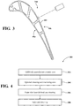
- Figure 3 is an expanded cross-sectional view of the core 200 along the line 3-3 of Figure 2 .
- the internal passage architecture 30 may include various passages, apertures and features.
- the component 20 may be a rotor blade that generally includes a root section 40, a platform section 50 and an airfoil section 60.
- the airfoil section 60 is defined by an outer airfoil wall surface 68 between a leading edge 70 and a trailing edge 72.
- the outer airfoil wall surface 68 defines a generally concave shaped portion forming a pressure side 68p and a generally convex shaped portion forming a suction side 68s typically shaped for use in a respective stage of a high pressure turbine section ( Figure 3 ).
- the outer airfoil wall surface 68 extends spanwise from the platform section 50 to a tip 74 of the airfoil section 60.
- the trailing edge 72 is spaced chordwise from the leading edge 70.
- the airfoil has a multiple of cavities or passages for cooling air as represented by the supply passages 80, 82, 84 which may extend through the root section 40.
- the passages extend into the interior of the airfoil section 60 and may extend in a serpentine or other non-linear fashion. It should be appreciated that the passage arrangement is merely illustrative and that various passages may alternatively or additionally be provided.
- one disclosed non-limiting embodiment of a method 300 to manufacture the core 200 initially includes additively manufacturing the core 200 (Step 302).
- the core 200 may be additively manufactured from a ceramic such as silica or alumina and a consumable part off the casting process.
- the core is created by injection molding of powdered ceramic and binder into a mold.
- Newer processes have been developed where the ceramic is suspended in a liquid binder than can be solidified using a laser or UV light. This process (called ceramic stereo lithography - CSL) typically utilizes an off-the-shelf lithographic fluid with a traditional ceramic suspended in the solution.
- the core 200 may optionally be cleaned or otherwise machined (Step 304). That is, the core 200 may be processed subsequent to the additive manufacturing.
- an outer skin 400 of the core 200 is consolidated (Step 306) via, for example, a laser ( Figure 3 ) prior to full core de-bind and sintering (step 308) in a furnace.
- Relatively low power lasers e.g., about 100 W, could be utilized to directly sinter silica.
- the silica in the outer skin 400 may be sintered at about 2192°F (1200°C).
- the outer skin 400 of the core 200 in this embodiment is about 1-2 mils (thousands of an inch, 0.0254 - 0.0508 mm).
- the transient thermal results of the core 200 under laser heating using a 100 W laser source for 0.050 seconds are shown. As is visible in the results, the local heating penetrates a shallow depth into the part leaving the larger portion deeper into the core unaffected ( Figure 6 ). This local heating reduces thermal strains in the part and reduces the risk of core cracking that a deeper heat penetration would produce.
- the laser is directed at the core 200 such that only the visibly exposed surfaces are impacted by the laser. That is, the laser only affects the portion of the core 200 that is within line-of-sight of the laser. That is, the outer skin 400 in which the sintering need not fully encapsulate the component, i.e., the laser does not raster the entire surface, for the process to provide structural rigidity during firing.
- the pre-sintered portions of the outer skin 400 provide retaining strength to the core 200 during the full furnace burn out process which thereby eliminates the need for setters and reduced development time for processing of a new additive core design.
- the process facilitates an increase in core yield by strengthening cores prior to firing by pre-sintering the surface and thereby decreases cost for processing of additive cores.
Landscapes
- Engineering & Computer Science (AREA)
- Mechanical Engineering (AREA)
- Molds, Cores, And Manufacturing Methods Thereof (AREA)
- Turbine Rotor Nozzle Sealing (AREA)
Abstract
Description
- The present disclosure relates generally to the utilization of a pre-sintering cycle to a green additive core that will allow the core to be self-supportive during the firing process.
- Gas turbine engines, such as those that power modem commercial and military aircraft, generally include a compressor section to pressurize an airflow, a combustor section to burn a hydrocarbon fuel in the presence of the pressurized air, and a turbine section to extract energy from the resultant combustion gases.
- Gas turbine engine hot section components such as blades and vanes are subject to high thermal loads for prolonged time periods. Other components also experience high thermal loads such as combustor, exhaust liner, blade outer air seal, and nozzle components. Historically, such components have implemented various air-cooling arrangements that permit the passage of air to facilitate cooling. In addition, the components are typically provided with various coatings such as thermal barrier coatings to further resist the thermal loads.
- The internal passage architecture may be produced through various processes such as investment cast, die cast, drill, Electron Discharge Machining ("EDM"), milling, welding, additive manufacturing, etc. Investment casting is a commonly used technique for forming metallic components having complex geometries, especially hollow components, and is used in the fabrication of superalloy gas turbine engine components.
- A primary mechanism in which to cool turbine gas path components is to utilize a series of in-wall channels to pass cooling air that is typically several hundreds of degrees colder than the gas path. These walls are typically cast-in to the airfoil and involve designs that distribute cooling air throughout the entirety of the part. The air is subsequently ejected either through film holes or other leakage apertures to the external flowpath environment. The traditional method of fabricating gas path components is to utilize an investment casting process that forms an interior core for the cooling channels. This core is typically a weak ceramic whose strength is significantly less than the component material. This material weakness has allowed for highly quality castings since the core typically collapses or 'crushes' during the solidification process.
- The advancement of additive manufacturing to manufacture components provides for extremely detailed, intricate, and adaptive feature designs. The ability to utilize this technology not only increases the design space of the parts but allows for a much higher degree of manufacturing robustness and adaptability. However, the current state-of-the-art in additive manufacturing does not allow for the creation of single crystal materials due to the nature of the process to be built by sintering or melting a powder substrate to form. It is however advantageous for the development die-less cores or the integration of cores and shells for use in the casting process.
- A part of processing the additive cores is to burn out the additive manufacturing binder material and sinters the particles together. During this process, the green additive core is placed within an oven and heated. The development of the heating cycle is such that experimentation is conducted to figure out how the cycle should be performed to retain the geometric shape of the part and eliminate sag or deflection of the part. To retain the shape of green cores during the firing process, secondary ceramic parts (typically called setters) are typically created and used to support the core within the chamber. The inclusion of these setters, along with the delicate nature of the cores, may result in significant costs within the development of a new core design.
- From a first aspect the invention provides a core for use in casting an internal cooling circuit within a gas turbine engine component, which can include a core body with an outer skin in which a core body additively manufacturing binder is locally eliminated.
- A further embodiment of the present disclosure may include the outer skin being sintered.
- A further embodiment of the present disclosure may include the outer skin of the core body being about 1-2 mils (thousands of an inch, 0.0254 - 0.0508 mm).
- A further embodiment of the present disclosure may include the core body being investment casted.
- A further embodiment of the present disclosure may include the core body including a ceramic material.
- A further embodiment of the present disclosure may include the refractory metal being in a "green" state with the binder.
- A further embodiment of the present disclosure may include the outer skin forming only a portion of the outer surface of the core body.
- A further embodiment of the present disclosure may include a directional energy source being utilized to form the outer skin.
- A further embodiment of the present disclosure may include the outer skin being formed only along a line of sight from the directional energy source of the outer surface of the core body.
- A further embodiment of the present disclosure may include the core body being fired in a furnace to de-bind and sinter visually shielded regions of the core body.
- A further embodiment of the present disclosure may include the outer skin forming only a visible region of the outer surface of the core body and the core body being fired to de-bind and sinter the visually shielded regions of the core body.
- A further embodiment of the present disclosure may include the visual regions being along a line of sight from a directional energy source directed at an outer surface of the core body.
- From another aspect, there is provided a method of manufacturing a core for casting a component including casting a core body for at least partially forming an internal passage architecture of a component; and forming an outer skin on the core body in which a core body additively manufacturing binder is locally eliminated.
- A further embodiment of the present disclosure may include eliminating the core body additive manufacturing binder from the core body.
- A further embodiment of the present disclosure may include using a directional energy source to form the outer skin.
- A further embodiment of the present disclosure may include using a laser to form the outer skin.
- A further embodiment of the present disclosure may include the laser being about 100W.
- A further embodiment of the present disclosure may include forming the outer skin only along a line of sight from a directional energy source of the outer surface of the core body.
- A further embodiment of the present disclosure may include the visual regions being along the line of sight from a directional energy source directed at an outer surface of the core body.
- A further embodiment of the present disclosure may include firing the core body to de-bind and sinter non-outer skin regions of the core body.
- A further embodiment of the present disclosure may include firing the core body to de-bind and sinter visually shielded regions of the core body.
- The foregoing features and elements may be combined in various combinations without exclusivity, unless expressly indicated otherwise. These features and elements as well as the operation of the invention will become more apparent in light of the following description and the accompanying drawings. It should be understood, however, the following description and drawings are intended to be exemplary in nature and non-limiting.
- Various features will become apparent to those skilled in the art from the following detailed description of the disclosed non-limiting embodiment. The drawings that accompany the detailed description can be briefly described as follows:
-
Figure 1 is a general schematic view of an exemplary actively cooled component as a representative workpiece with an additively manufactured core; -
Figure 2 is a general schematic view of an additively manufactured core; -
Figure 3 is an expanded cross section of the additively manufactured core along the line 3-3 ofFigure 2 illustrating the outer skin; -
Figure 4 is a flow diagram of a method of manufacturing a core for casting a component according to a non-liming embodiment; -
Figure 5 is an expanded cross section of the core in which a laser is utilized to form an outer skin to allow the core to be self-supportive during the firing process; and -
Figure 6 is a graphical representation of the laser depth effect on the core. -
Figure 1 schematically illustrates a general perspective view of anexemplary component 20, e.g., an actively cooled airfoil segment of a gas turbine engine. It should be appreciated that although a particular component type is illustrated in the disclosed non-limiting embodiment, other components, such as blades, vanes, exhaust duct liners, nozzle flaps, and nozzle seals, as well as other actively cooled components will also benefit herefrom. These components, for example, operate in challenging high-temperature environments such as a hot section of a gas turbine engine and have aggressive requirements in terms of durability and temperature allowances. - The
component 20 includesinternal passage architecture 30 formed by a core 200 (Figure 2 ).Figure 3 is an expanded cross-sectional view of thecore 200 along the line 3-3 ofFigure 2 . Theinternal passage architecture 30 may include various passages, apertures and features. In this example, thecomponent 20 may be a rotor blade that generally includes aroot section 40, aplatform section 50 and anairfoil section 60. Theairfoil section 60 is defined by an outerairfoil wall surface 68 between aleading edge 70 and a trailingedge 72. The outerairfoil wall surface 68 defines a generally concave shaped portion forming apressure side 68p and a generally convex shaped portion forming asuction side 68s typically shaped for use in a respective stage of a high pressure turbine section (Figure 3 ). - The outer
airfoil wall surface 68 extends spanwise from theplatform section 50 to atip 74 of theairfoil section 60. The trailingedge 72 is spaced chordwise from the leadingedge 70. The airfoil has a multiple of cavities or passages for cooling air as represented by thesupply passages root section 40. The passages extend into the interior of theairfoil section 60 and may extend in a serpentine or other non-linear fashion. It should be appreciated that the passage arrangement is merely illustrative and that various passages may alternatively or additionally be provided. - With reference to
Figure 4 , one disclosed non-limiting embodiment of amethod 300 to manufacture thecore 200 initially includes additively manufacturing the core 200 (Step 302). It should be appreciated that although a particular remanufacture method is depicted, other manufacture, repair, and/or remanufacture processes and methods will also benefit herefrom. Thecore 200 may be additively manufactured from a ceramic such as silica or alumina and a consumable part off the casting process. In traditional casting processes, the core is created by injection molding of powdered ceramic and binder into a mold. Newer processes have been developed where the ceramic is suspended in a liquid binder than can be solidified using a laser or UV light. This process (called ceramic stereo lithography - CSL) typically utilizes an off-the-shelf lithographic fluid with a traditional ceramic suspended in the solution. - Next, the
core 200 may optionally be cleaned or otherwise machined (Step 304). That is, thecore 200 may be processed subsequent to the additive manufacturing. - Next, an
outer skin 400 of thecore 200 is consolidated (Step 306) via, for example, a laser (Figure 3 ) prior to full core de-bind and sintering (step 308) in a furnace. Relatively low power lasers, e.g., about 100 W, could be utilized to directly sinter silica. In one example, the silica in theouter skin 400 may be sintered at about 2192°F (1200°C). Theouter skin 400 of the core 200 in this embodiment is about 1-2 mils (thousands of an inch, 0.0254 - 0.0508 mm). - In one example, the transient thermal results of the
core 200 under laser heating using a 100 W laser source for 0.050 seconds (Figure 5 ) are shown. As is visible in the results, the local heating penetrates a shallow depth into the part leaving the larger portion deeper into the core unaffected (Figure 6 ). This local heating reduces thermal strains in the part and reduces the risk of core cracking that a deeper heat penetration would produce. - In this embodiment the laser is directed at the core 200 such that only the visibly exposed surfaces are impacted by the laser. That is, the laser only affects the portion of the core 200 that is within line-of-sight of the laser. That is, the
outer skin 400 in which the sintering need not fully encapsulate the component, i.e., the laser does not raster the entire surface, for the process to provide structural rigidity during firing. - The pre-sintered portions of the
outer skin 400 provide retaining strength to thecore 200 during the full furnace burn out process which thereby eliminates the need for setters and reduced development time for processing of a new additive core design. The process facilitates an increase in core yield by strengthening cores prior to firing by pre-sintering the surface and thereby decreases cost for processing of additive cores. - The use of the terms "a," "an," "the," and similar references in the context of description (especially in the context of the following claims) are to be construed to cover both the singular and the plural, unless otherwise indicated herein or specifically contradicted by context. The modifier "about" used in connection with a quantity is inclusive of the stated value and has the meaning dictated by the context (e.g., it includes the degree of error associated with measurement of the particular quantity). All ranges disclosed herein are inclusive of the endpoints, and the endpoints are independently combinable with each other. It should be appreciated that relative positional terms such as "forward," "aft," "upper," "lower," "above," "below," and the like are with reference to the normal operational attitude of the vehicle and should not be considered otherwise limiting.
- Although the different non-limiting embodiments have specific illustrated components, the embodiments of this invention are not limited to those particular combinations. It is possible to use some of the components or features from any of the non-limiting embodiments in combination with features or components from any of the other non-limiting embodiments.
- It should be appreciated that like reference numerals identify corresponding or similar elements throughout the several drawings. It should also be appreciated that although a particular component arrangement is disclosed in the illustrated embodiment, other arrangements will benefit herefrom.
- Although particular step sequences are shown, described, and claimed, it should be appreciated that steps may be performed in any order, separated or combined unless otherwise indicated and will still benefit from the present disclosure.
- The foregoing description is exemplary rather than defined by the limitations within. Various non-limiting embodiments are disclosed herein, however, one of ordinary skill in the art would recognize that various modifications and variations in light of the above teachings will fall within the scope of the appended claims. It is therefore to be appreciated that within the scope of the appended claims, the disclosure may be practiced other than as specifically described. For that reason the appended claims should be studied to determine true scope and content.
Claims (15)
- A method of manufacturing a core (200) for casting a component (20), comprising:casting a core body for at least partially forming an internal passage architecture (30) of a component (20);forming an outer skin (400) on the core body; andlocally eliminating a core body additive manufacturing binder.
- The method as recited in claim 1, further comprising using a directional energy source to form the outer skin (400).
- The method as recited in claim 1 or 2, further comprising using a laser to form the outer skin (400).
- The method as recited in claim 3, wherein the laser is about 100W.
- The method as recited in any preceding claim, further comprising forming the outer skin (400) only along a line of sight from a directional energy source of an outer surface of the core body.
- The method as recited in claim 5, wherein the visual regions are along the line of sight from the directional energy source directed at an outer surface of the core body.
- The method as recited in any preceding claim, further comprising firing the core body to de-bind and sinter non-outer skin regions of the core body.
- The method as recited in any preceding claim, further comprising firing the core body to de-bind and sinter visually shielded regions of the core body.
- A core (200) for use in casting an internal cooling circuit (30) within a gas turbine engine component (20), the core (200) comprising a core body with an outer skin (400) in which a core body additive manufacturing binder has been locally eliminated.
- The core (200) as recited in claim 9, wherein the outer skin (400) has been sintered.
- The core (200) as recited in claim 9 or 10, wherein the outer skin (400) of the core body is about 1-2 mils (thousands of an inch) (0.0254 - 0.0508 mm).
- The core (200) as recited in any of claims 9 to 11, wherein the core body has been investment casted.
- The core (200) as recited in any of claims 9 to 12, wherein the core body includes a ceramic material.
- The core (200) as recited in claim 13, wherein the ceramic material is in a "green" state with the binder.
- The core (200) as recited in any of claims 9 to 14, wherein the outer skin (400) forms only a portion of the outer surface of the core body.
Applications Claiming Priority (1)
| Application Number | Priority Date | Filing Date | Title |
|---|---|---|---|
| US15/214,747 US10179362B2 (en) | 2016-07-20 | 2016-07-20 | System and process to provide self-supporting additive manufactured ceramic core |
Publications (2)
| Publication Number | Publication Date |
|---|---|
| EP3272440A1 true EP3272440A1 (en) | 2018-01-24 |
| EP3272440B1 EP3272440B1 (en) | 2019-03-20 |
Family
ID=59383489
Family Applications (1)
| Application Number | Title | Priority Date | Filing Date |
|---|---|---|---|
| EP17182376.8A Active EP3272440B1 (en) | 2016-07-20 | 2017-07-20 | System and process to provide self-supporting additive manufactured ceramic core |
Country Status (2)
| Country | Link |
|---|---|
| US (2) | US10179362B2 (en) |
| EP (1) | EP3272440B1 (en) |
Families Citing this family (1)
| Publication number | Priority date | Publication date | Assignee | Title |
|---|---|---|---|---|
| US12594594B2 (en) | 2022-09-22 | 2026-04-07 | Blasch Precision Ceramics, Inc. | Hybrid setter for investment casting cores and method of using |
Citations (2)
| Publication number | Priority date | Publication date | Assignee | Title |
|---|---|---|---|---|
| US20090189315A1 (en) * | 2005-11-22 | 2009-07-30 | Bego Bremer Goldschlagerei Wilh. Herbst Gmbh & Co. Kg | Method for the Production of a Ceramic Shaped Body and a Shaped Body Produced by the Method |
| US20150306657A1 (en) * | 2014-04-24 | 2015-10-29 | Howmet Corporation | Ceramic casting core made by additive manufacturing |
Family Cites Families (10)
| Publication number | Priority date | Publication date | Assignee | Title |
|---|---|---|---|---|
| JP3215881B2 (en) * | 1994-05-27 | 2001-10-09 | イーオーエス ゲゼルシャフト ミット ベシュレンクテル ハフツング イレクトロ オプティカル システムズ | Methods used for casting technology |
| US8047789B1 (en) | 2007-10-19 | 2011-11-01 | Florida Turbine Technologies, Inc. | Turbine airfoil |
| US7866950B1 (en) | 2007-12-21 | 2011-01-11 | Florida Turbine Technologies, Inc. | Turbine blade with spar and shell |
| US8057183B1 (en) | 2008-12-16 | 2011-11-15 | Florida Turbine Technologies, Inc. | Light weight and highly cooled turbine blade |
| US8066483B1 (en) | 2008-12-18 | 2011-11-29 | Florida Turbine Technologies, Inc. | Turbine airfoil with non-parallel pin fins |
| US8322988B1 (en) | 2009-01-09 | 2012-12-04 | Florida Turbine Technologies, Inc. | Air cooled turbine airfoil with sequential impingement cooling |
| US8096766B1 (en) | 2009-01-09 | 2012-01-17 | Florida Turbine Technologies, Inc. | Air cooled turbine airfoil with sequential cooling |
| US8109726B2 (en) | 2009-01-19 | 2012-02-07 | Siemens Energy, Inc. | Turbine blade with micro channel cooling system |
| US8317475B1 (en) | 2010-01-25 | 2012-11-27 | Florida Turbine Technologies, Inc. | Turbine airfoil with micro cooling channels |
| US9435211B2 (en) * | 2014-05-09 | 2016-09-06 | United Technologies Corporation | Method for forming components using additive manufacturing and re-melt |
-
2016
- 2016-07-20 US US15/214,747 patent/US10179362B2/en active Active
-
2017
- 2017-07-20 EP EP17182376.8A patent/EP3272440B1/en active Active
-
2018
- 2018-12-10 US US16/214,651 patent/US10549338B2/en active Active
Patent Citations (2)
| Publication number | Priority date | Publication date | Assignee | Title |
|---|---|---|---|---|
| US20090189315A1 (en) * | 2005-11-22 | 2009-07-30 | Bego Bremer Goldschlagerei Wilh. Herbst Gmbh & Co. Kg | Method for the Production of a Ceramic Shaped Body and a Shaped Body Produced by the Method |
| US20150306657A1 (en) * | 2014-04-24 | 2015-10-29 | Howmet Corporation | Ceramic casting core made by additive manufacturing |
Also Published As
| Publication number | Publication date |
|---|---|
| US20190111471A1 (en) | 2019-04-18 |
| US20180021848A1 (en) | 2018-01-25 |
| US10179362B2 (en) | 2019-01-15 |
| EP3272440B1 (en) | 2019-03-20 |
| US10549338B2 (en) | 2020-02-04 |
Similar Documents
| Publication | Publication Date | Title |
|---|---|---|
| US11059093B2 (en) | Additively manufactured core for use in casting an internal cooling circuit of a gas turbine engine component | |
| US9458725B2 (en) | Method and system for providing cooling for turbine components | |
| EP3415718B1 (en) | Gas turbine engine components with air-cooling features, and related methods of manufacturing the same | |
| CN104653240B (en) | Improvement turbine components with internal cooling auxiliary element and the method for it | |
| EP1211385B1 (en) | Making cooling channels in turbine components | |
| EP3068975B1 (en) | Gas turbine engine component and corresponding methods of manufacturing | |
| US10415394B2 (en) | Gas turbine engine blade with ceramic tip and cooling arrangement | |
| EP3115147A1 (en) | Systems and methods for turbine blade repair | |
| CN106246237A (en) | There are the hot gas path parts of nearly wall air-circulation features | |
| JP7317944B2 (en) | Method of forming a hot gas path component for a gas turbine engine | |
| US10364683B2 (en) | Gas turbine engine component cooling passage turbulator | |
| JP2014163389A (en) | Cooled article | |
| US10549338B2 (en) | System and process to provide self-supporting additive manufactured ceramic core | |
| US12497896B2 (en) | Airfoil assembly with platform film holes | |
| EP3100819A1 (en) | Repair or remanufacture of cooled components with an oxidation resistant braze |
Legal Events
| Date | Code | Title | Description |
|---|---|---|---|
| PUAI | Public reference made under article 153(3) epc to a published international application that has entered the european phase |
Free format text: ORIGINAL CODE: 0009012 |
|
| STAA | Information on the status of an ep patent application or granted ep patent |
Free format text: STATUS: THE APPLICATION HAS BEEN PUBLISHED |
|
| AK | Designated contracting states |
Kind code of ref document: A1 Designated state(s): AL AT BE BG CH CY CZ DE DK EE ES FI FR GB GR HR HU IE IS IT LI LT LU LV MC MK MT NL NO PL PT RO RS SE SI SK SM TR |
|
| AX | Request for extension of the european patent |
Extension state: BA ME |
|
| STAA | Information on the status of an ep patent application or granted ep patent |
Free format text: STATUS: REQUEST FOR EXAMINATION WAS MADE |
|
| 17P | Request for examination filed |
Effective date: 20180724 |
|
| RBV | Designated contracting states (corrected) |
Designated state(s): AL AT BE BG CH CY CZ DE DK EE ES FI FR GB GR HR HU IE IS IT LI LT LU LV MC MK MT NL NO PL PT RO RS SE SI SK SM TR |
|
| GRAP | Despatch of communication of intention to grant a patent |
Free format text: ORIGINAL CODE: EPIDOSNIGR1 |
|
| STAA | Information on the status of an ep patent application or granted ep patent |
Free format text: STATUS: GRANT OF PATENT IS INTENDED |
|
| INTG | Intention to grant announced |
Effective date: 20180926 |
|
| GRAS | Grant fee paid |
Free format text: ORIGINAL CODE: EPIDOSNIGR3 |
|
| GRAA | (expected) grant |
Free format text: ORIGINAL CODE: 0009210 |
|
| STAA | Information on the status of an ep patent application or granted ep patent |
Free format text: STATUS: THE PATENT HAS BEEN GRANTED |
|
| AK | Designated contracting states |
Kind code of ref document: B1 Designated state(s): AL AT BE BG CH CY CZ DE DK EE ES FI FR GB GR HR HU IE IS IT LI LT LU LV MC MK MT NL NO PL PT RO RS SE SI SK SM TR |
|
| REG | Reference to a national code |
Ref country code: GB Ref legal event code: FG4D |
|
| REG | Reference to a national code |
Ref country code: CH Ref legal event code: EP |
|
| REG | Reference to a national code |
Ref country code: DE Ref legal event code: R096 Ref document number: 602017002804 Country of ref document: DE |
|
| REG | Reference to a national code |
Ref country code: AT Ref legal event code: REF Ref document number: 1110030 Country of ref document: AT Kind code of ref document: T Effective date: 20190415 |
|
| REG | Reference to a national code |
Ref country code: IE Ref legal event code: FG4D |
|
| REG | Reference to a national code |
Ref country code: NL Ref legal event code: MP Effective date: 20190320 |
|
| PG25 | Lapsed in a contracting state [announced via postgrant information from national office to epo] |
Ref country code: SE Free format text: LAPSE BECAUSE OF FAILURE TO SUBMIT A TRANSLATION OF THE DESCRIPTION OR TO PAY THE FEE WITHIN THE PRESCRIBED TIME-LIMIT Effective date: 20190320 Ref country code: LT Free format text: LAPSE BECAUSE OF FAILURE TO SUBMIT A TRANSLATION OF THE DESCRIPTION OR TO PAY THE FEE WITHIN THE PRESCRIBED TIME-LIMIT Effective date: 20190320 Ref country code: NO Free format text: LAPSE BECAUSE OF FAILURE TO SUBMIT A TRANSLATION OF THE DESCRIPTION OR TO PAY THE FEE WITHIN THE PRESCRIBED TIME-LIMIT Effective date: 20190620 Ref country code: FI Free format text: LAPSE BECAUSE OF FAILURE TO SUBMIT A TRANSLATION OF THE DESCRIPTION OR TO PAY THE FEE WITHIN THE PRESCRIBED TIME-LIMIT Effective date: 20190320 |
|
| REG | Reference to a national code |
Ref country code: LT Ref legal event code: MG4D |
|
| PG25 | Lapsed in a contracting state [announced via postgrant information from national office to epo] |
Ref country code: NL Free format text: LAPSE BECAUSE OF FAILURE TO SUBMIT A TRANSLATION OF THE DESCRIPTION OR TO PAY THE FEE WITHIN THE PRESCRIBED TIME-LIMIT Effective date: 20190320 Ref country code: RS Free format text: LAPSE BECAUSE OF FAILURE TO SUBMIT A TRANSLATION OF THE DESCRIPTION OR TO PAY THE FEE WITHIN THE PRESCRIBED TIME-LIMIT Effective date: 20190320 Ref country code: LV Free format text: LAPSE BECAUSE OF FAILURE TO SUBMIT A TRANSLATION OF THE DESCRIPTION OR TO PAY THE FEE WITHIN THE PRESCRIBED TIME-LIMIT Effective date: 20190320 Ref country code: HR Free format text: LAPSE BECAUSE OF FAILURE TO SUBMIT A TRANSLATION OF THE DESCRIPTION OR TO PAY THE FEE WITHIN THE PRESCRIBED TIME-LIMIT Effective date: 20190320 Ref country code: GR Free format text: LAPSE BECAUSE OF FAILURE TO SUBMIT A TRANSLATION OF THE DESCRIPTION OR TO PAY THE FEE WITHIN THE PRESCRIBED TIME-LIMIT Effective date: 20190621 Ref country code: BG Free format text: LAPSE BECAUSE OF FAILURE TO SUBMIT A TRANSLATION OF THE DESCRIPTION OR TO PAY THE FEE WITHIN THE PRESCRIBED TIME-LIMIT Effective date: 20190620 |
|
| REG | Reference to a national code |
Ref country code: AT Ref legal event code: MK05 Ref document number: 1110030 Country of ref document: AT Kind code of ref document: T Effective date: 20190320 |
|
| PG25 | Lapsed in a contracting state [announced via postgrant information from national office to epo] |
Ref country code: EE Free format text: LAPSE BECAUSE OF FAILURE TO SUBMIT A TRANSLATION OF THE DESCRIPTION OR TO PAY THE FEE WITHIN THE PRESCRIBED TIME-LIMIT Effective date: 20190320 Ref country code: SK Free format text: LAPSE BECAUSE OF FAILURE TO SUBMIT A TRANSLATION OF THE DESCRIPTION OR TO PAY THE FEE WITHIN THE PRESCRIBED TIME-LIMIT Effective date: 20190320 Ref country code: ES Free format text: LAPSE BECAUSE OF FAILURE TO SUBMIT A TRANSLATION OF THE DESCRIPTION OR TO PAY THE FEE WITHIN THE PRESCRIBED TIME-LIMIT Effective date: 20190320 Ref country code: PT Free format text: LAPSE BECAUSE OF FAILURE TO SUBMIT A TRANSLATION OF THE DESCRIPTION OR TO PAY THE FEE WITHIN THE PRESCRIBED TIME-LIMIT Effective date: 20190720 Ref country code: AL Free format text: LAPSE BECAUSE OF FAILURE TO SUBMIT A TRANSLATION OF THE DESCRIPTION OR TO PAY THE FEE WITHIN THE PRESCRIBED TIME-LIMIT Effective date: 20190320 Ref country code: RO Free format text: LAPSE BECAUSE OF FAILURE TO SUBMIT A TRANSLATION OF THE DESCRIPTION OR TO PAY THE FEE WITHIN THE PRESCRIBED TIME-LIMIT Effective date: 20190320 Ref country code: CZ Free format text: LAPSE BECAUSE OF FAILURE TO SUBMIT A TRANSLATION OF THE DESCRIPTION OR TO PAY THE FEE WITHIN THE PRESCRIBED TIME-LIMIT Effective date: 20190320 Ref country code: IT Free format text: LAPSE BECAUSE OF FAILURE TO SUBMIT A TRANSLATION OF THE DESCRIPTION OR TO PAY THE FEE WITHIN THE PRESCRIBED TIME-LIMIT Effective date: 20190320 |
|
| PG25 | Lapsed in a contracting state [announced via postgrant information from national office to epo] |
Ref country code: SM Free format text: LAPSE BECAUSE OF FAILURE TO SUBMIT A TRANSLATION OF THE DESCRIPTION OR TO PAY THE FEE WITHIN THE PRESCRIBED TIME-LIMIT Effective date: 20190320 Ref country code: PL Free format text: LAPSE BECAUSE OF FAILURE TO SUBMIT A TRANSLATION OF THE DESCRIPTION OR TO PAY THE FEE WITHIN THE PRESCRIBED TIME-LIMIT Effective date: 20190320 |
|
| PG25 | Lapsed in a contracting state [announced via postgrant information from national office to epo] |
Ref country code: IS Free format text: LAPSE BECAUSE OF FAILURE TO SUBMIT A TRANSLATION OF THE DESCRIPTION OR TO PAY THE FEE WITHIN THE PRESCRIBED TIME-LIMIT Effective date: 20190720 Ref country code: AT Free format text: LAPSE BECAUSE OF FAILURE TO SUBMIT A TRANSLATION OF THE DESCRIPTION OR TO PAY THE FEE WITHIN THE PRESCRIBED TIME-LIMIT Effective date: 20190320 |
|
| REG | Reference to a national code |
Ref country code: DE Ref legal event code: R097 Ref document number: 602017002804 Country of ref document: DE |
|
| PLBE | No opposition filed within time limit |
Free format text: ORIGINAL CODE: 0009261 |
|
| STAA | Information on the status of an ep patent application or granted ep patent |
Free format text: STATUS: NO OPPOSITION FILED WITHIN TIME LIMIT |
|
| PG25 | Lapsed in a contracting state [announced via postgrant information from national office to epo] |
Ref country code: DK Free format text: LAPSE BECAUSE OF FAILURE TO SUBMIT A TRANSLATION OF THE DESCRIPTION OR TO PAY THE FEE WITHIN THE PRESCRIBED TIME-LIMIT Effective date: 20190320 |
|
| 26N | No opposition filed |
Effective date: 20200102 |
|
| PG25 | Lapsed in a contracting state [announced via postgrant information from national office to epo] |
Ref country code: MC Free format text: LAPSE BECAUSE OF FAILURE TO SUBMIT A TRANSLATION OF THE DESCRIPTION OR TO PAY THE FEE WITHIN THE PRESCRIBED TIME-LIMIT Effective date: 20190320 Ref country code: SI Free format text: LAPSE BECAUSE OF FAILURE TO SUBMIT A TRANSLATION OF THE DESCRIPTION OR TO PAY THE FEE WITHIN THE PRESCRIBED TIME-LIMIT Effective date: 20190320 |
|
| PG25 | Lapsed in a contracting state [announced via postgrant information from national office to epo] |
Ref country code: TR Free format text: LAPSE BECAUSE OF FAILURE TO SUBMIT A TRANSLATION OF THE DESCRIPTION OR TO PAY THE FEE WITHIN THE PRESCRIBED TIME-LIMIT Effective date: 20190320 |
|
| REG | Reference to a national code |
Ref country code: BE Ref legal event code: MM Effective date: 20190731 |
|
| PG25 | Lapsed in a contracting state [announced via postgrant information from national office to epo] |
Ref country code: LU Free format text: LAPSE BECAUSE OF NON-PAYMENT OF DUE FEES Effective date: 20190720 Ref country code: BE Free format text: LAPSE BECAUSE OF NON-PAYMENT OF DUE FEES Effective date: 20190731 |
|
| PG25 | Lapsed in a contracting state [announced via postgrant information from national office to epo] |
Ref country code: IE Free format text: LAPSE BECAUSE OF NON-PAYMENT OF DUE FEES Effective date: 20190720 |
|
| REG | Reference to a national code |
Ref country code: CH Ref legal event code: PL |
|
| PG25 | Lapsed in a contracting state [announced via postgrant information from national office to epo] |
Ref country code: LI Free format text: LAPSE BECAUSE OF NON-PAYMENT OF DUE FEES Effective date: 20200731 Ref country code: CH Free format text: LAPSE BECAUSE OF NON-PAYMENT OF DUE FEES Effective date: 20200731 |
|
| PG25 | Lapsed in a contracting state [announced via postgrant information from national office to epo] |
Ref country code: CY Free format text: LAPSE BECAUSE OF FAILURE TO SUBMIT A TRANSLATION OF THE DESCRIPTION OR TO PAY THE FEE WITHIN THE PRESCRIBED TIME-LIMIT Effective date: 20190320 |
|
| PG25 | Lapsed in a contracting state [announced via postgrant information from national office to epo] |
Ref country code: MT Free format text: LAPSE BECAUSE OF FAILURE TO SUBMIT A TRANSLATION OF THE DESCRIPTION OR TO PAY THE FEE WITHIN THE PRESCRIBED TIME-LIMIT Effective date: 20190320 Ref country code: HU Free format text: LAPSE BECAUSE OF FAILURE TO SUBMIT A TRANSLATION OF THE DESCRIPTION OR TO PAY THE FEE WITHIN THE PRESCRIBED TIME-LIMIT; INVALID AB INITIO Effective date: 20170720 |
|
| PG25 | Lapsed in a contracting state [announced via postgrant information from national office to epo] |
Ref country code: MK Free format text: LAPSE BECAUSE OF FAILURE TO SUBMIT A TRANSLATION OF THE DESCRIPTION OR TO PAY THE FEE WITHIN THE PRESCRIBED TIME-LIMIT Effective date: 20190320 |
|
| REG | Reference to a national code |
Ref country code: DE Ref legal event code: R081 Ref document number: 602017002804 Country of ref document: DE Owner name: RAYTHEON TECHNOLOGIES CORPORATION (N.D.GES.D.S, US Free format text: FORMER OWNER: UNITED TECHNOLOGIES CORPORATION, FARMINGTON, CONN., US Ref country code: DE Ref legal event code: R081 Ref document number: 602017002804 Country of ref document: DE Owner name: RTX CORPORATION (N.D.GES.D. STAATES DELAWARE),, US Free format text: FORMER OWNER: UNITED TECHNOLOGIES CORPORATION, FARMINGTON, CONN., US |
|
| P01 | Opt-out of the competence of the unified patent court (upc) registered |
Effective date: 20230520 |
|
| PGFP | Annual fee paid to national office [announced via postgrant information from national office to epo] |
Ref country code: GB Payment date: 20250619 Year of fee payment: 9 |
|
| PGFP | Annual fee paid to national office [announced via postgrant information from national office to epo] |
Ref country code: FR Payment date: 20250619 Year of fee payment: 9 |
|
| PGFP | Annual fee paid to national office [announced via postgrant information from national office to epo] |
Ref country code: DE Payment date: 20250620 Year of fee payment: 9 |
|
| REG | Reference to a national code |
Ref country code: DE Ref legal event code: R081 Ref document number: 602017002804 Country of ref document: DE Owner name: RTX CORPORATION (N.D.GES.D. STAATES DELAWARE),, US Free format text: FORMER OWNER: RAYTHEON TECHNOLOGIES CORPORATION (N.D.GES.D.STAATES DELAWARE), ARLINGTON, VA, US |