EP3272377A1 - Infusion state detection system - Google Patents
Infusion state detection system Download PDFInfo
- Publication number
- EP3272377A1 EP3272377A1 EP16764530.8A EP16764530A EP3272377A1 EP 3272377 A1 EP3272377 A1 EP 3272377A1 EP 16764530 A EP16764530 A EP 16764530A EP 3272377 A1 EP3272377 A1 EP 3272377A1
- Authority
- EP
- European Patent Office
- Prior art keywords
- pressure
- infusion
- pressure value
- infusion line
- liquid delivery
- Prior art date
- Legal status (The legal status is an assumption and is not a legal conclusion. Google has not performed a legal analysis and makes no representation as to the accuracy of the status listed.)
- Granted
Links
Images




Classifications
-
- A—HUMAN NECESSITIES
- A61—MEDICAL OR VETERINARY SCIENCE; HYGIENE
- A61M—DEVICES FOR INTRODUCING MEDIA INTO, OR ONTO, THE BODY; DEVICES FOR TRANSDUCING BODY MEDIA OR FOR TAKING MEDIA FROM THE BODY; DEVICES FOR PRODUCING OR ENDING SLEEP OR STUPOR
- A61M5/00—Devices for bringing media into the body in a subcutaneous, intra-vascular or intramuscular way; Accessories therefor, e.g. filling or cleaning devices, arm-rests
- A61M5/14—Infusion devices, e.g. infusing by gravity; Blood infusion; Accessories therefor
- A61M5/168—Means for controlling media flow to the body or for metering media to the body, e.g. drip meters, counters ; Monitoring media flow to the body
- A61M5/16831—Monitoring, detecting, signalling or eliminating infusion flow anomalies
- A61M5/16854—Monitoring, detecting, signalling or eliminating infusion flow anomalies by monitoring line pressure
-
- A—HUMAN NECESSITIES
- A61—MEDICAL OR VETERINARY SCIENCE; HYGIENE
- A61M—DEVICES FOR INTRODUCING MEDIA INTO, OR ONTO, THE BODY; DEVICES FOR TRANSDUCING BODY MEDIA OR FOR TAKING MEDIA FROM THE BODY; DEVICES FOR PRODUCING OR ENDING SLEEP OR STUPOR
- A61M5/00—Devices for bringing media into the body in a subcutaneous, intra-vascular or intramuscular way; Accessories therefor, e.g. filling or cleaning devices, arm-rests
- A61M5/14—Infusion devices, e.g. infusing by gravity; Blood infusion; Accessories therefor
- A61M5/168—Means for controlling media flow to the body or for metering media to the body, e.g. drip meters, counters ; Monitoring media flow to the body
- A61M5/16831—Monitoring, detecting, signalling or eliminating infusion flow anomalies
- A61M5/16854—Monitoring, detecting, signalling or eliminating infusion flow anomalies by monitoring line pressure
- A61M5/16859—Evaluation of pressure response, e.g. to an applied pulse
-
- A—HUMAN NECESSITIES
- A61—MEDICAL OR VETERINARY SCIENCE; HYGIENE
- A61M—DEVICES FOR INTRODUCING MEDIA INTO, OR ONTO, THE BODY; DEVICES FOR TRANSDUCING BODY MEDIA OR FOR TAKING MEDIA FROM THE BODY; DEVICES FOR PRODUCING OR ENDING SLEEP OR STUPOR
- A61M5/00—Devices for bringing media into the body in a subcutaneous, intra-vascular or intramuscular way; Accessories therefor, e.g. filling or cleaning devices, arm-rests
- A61M5/14—Infusion devices, e.g. infusing by gravity; Blood infusion; Accessories therefor
- A61M5/168—Means for controlling media flow to the body or for metering media to the body, e.g. drip meters, counters ; Monitoring media flow to the body
-
- A—HUMAN NECESSITIES
- A61—MEDICAL OR VETERINARY SCIENCE; HYGIENE
- A61J—CONTAINERS SPECIALLY ADAPTED FOR MEDICAL OR PHARMACEUTICAL PURPOSES; DEVICES OR METHODS SPECIALLY ADAPTED FOR BRINGING PHARMACEUTICAL PRODUCTS INTO PARTICULAR PHYSICAL OR ADMINISTERING FORMS; DEVICES FOR ADMINISTERING FOOD OR MEDICINES ORALLY; BABY COMFORTERS; DEVICES FOR RECEIVING SPITTLE
- A61J1/00—Containers specially adapted for medical or pharmaceutical purposes
- A61J1/05—Containers specially adapted for medical or pharmaceutical purposes for collecting, storing or administering blood, plasma or medical fluids ; Infusion or perfusion containers
- A61J1/10—Bag-type containers
-
- A—HUMAN NECESSITIES
- A61—MEDICAL OR VETERINARY SCIENCE; HYGIENE
- A61M—DEVICES FOR INTRODUCING MEDIA INTO, OR ONTO, THE BODY; DEVICES FOR TRANSDUCING BODY MEDIA OR FOR TAKING MEDIA FROM THE BODY; DEVICES FOR PRODUCING OR ENDING SLEEP OR STUPOR
- A61M5/00—Devices for bringing media into the body in a subcutaneous, intra-vascular or intramuscular way; Accessories therefor, e.g. filling or cleaning devices, arm-rests
- A61M5/14—Infusion devices, e.g. infusing by gravity; Blood infusion; Accessories therefor
- A61M5/168—Means for controlling media flow to the body or for metering media to the body, e.g. drip meters, counters ; Monitoring media flow to the body
- A61M5/16831—Monitoring, detecting, signalling or eliminating infusion flow anomalies
- A61M2005/16863—Occlusion detection
-
- A—HUMAN NECESSITIES
- A61—MEDICAL OR VETERINARY SCIENCE; HYGIENE
- A61M—DEVICES FOR INTRODUCING MEDIA INTO, OR ONTO, THE BODY; DEVICES FOR TRANSDUCING BODY MEDIA OR FOR TAKING MEDIA FROM THE BODY; DEVICES FOR PRODUCING OR ENDING SLEEP OR STUPOR
- A61M5/00—Devices for bringing media into the body in a subcutaneous, intra-vascular or intramuscular way; Accessories therefor, e.g. filling or cleaning devices, arm-rests
- A61M5/14—Infusion devices, e.g. infusing by gravity; Blood infusion; Accessories therefor
- A61M5/168—Means for controlling media flow to the body or for metering media to the body, e.g. drip meters, counters ; Monitoring media flow to the body
- A61M5/16831—Monitoring, detecting, signalling or eliminating infusion flow anomalies
- A61M2005/16863—Occlusion detection
- A61M2005/16868—Downstream occlusion sensors
-
- A—HUMAN NECESSITIES
- A61—MEDICAL OR VETERINARY SCIENCE; HYGIENE
- A61M—DEVICES FOR INTRODUCING MEDIA INTO, OR ONTO, THE BODY; DEVICES FOR TRANSDUCING BODY MEDIA OR FOR TAKING MEDIA FROM THE BODY; DEVICES FOR PRODUCING OR ENDING SLEEP OR STUPOR
- A61M2205/00—General characteristics of the apparatus
- A61M2205/15—Detection of leaks
-
- A—HUMAN NECESSITIES
- A61—MEDICAL OR VETERINARY SCIENCE; HYGIENE
- A61M—DEVICES FOR INTRODUCING MEDIA INTO, OR ONTO, THE BODY; DEVICES FOR TRANSDUCING BODY MEDIA OR FOR TAKING MEDIA FROM THE BODY; DEVICES FOR PRODUCING OR ENDING SLEEP OR STUPOR
- A61M2205/00—General characteristics of the apparatus
- A61M2205/18—General characteristics of the apparatus with alarm
-
- A—HUMAN NECESSITIES
- A61—MEDICAL OR VETERINARY SCIENCE; HYGIENE
- A61M—DEVICES FOR INTRODUCING MEDIA INTO, OR ONTO, THE BODY; DEVICES FOR TRANSDUCING BODY MEDIA OR FOR TAKING MEDIA FROM THE BODY; DEVICES FOR PRODUCING OR ENDING SLEEP OR STUPOR
- A61M2205/00—General characteristics of the apparatus
- A61M2205/33—Controlling, regulating or measuring
- A61M2205/3331—Pressure; Flow
- A61M2205/3334—Measuring or controlling the flow rate
-
- A—HUMAN NECESSITIES
- A61—MEDICAL OR VETERINARY SCIENCE; HYGIENE
- A61M—DEVICES FOR INTRODUCING MEDIA INTO, OR ONTO, THE BODY; DEVICES FOR TRANSDUCING BODY MEDIA OR FOR TAKING MEDIA FROM THE BODY; DEVICES FOR PRODUCING OR ENDING SLEEP OR STUPOR
- A61M2205/00—General characteristics of the apparatus
- A61M2205/33—Controlling, regulating or measuring
- A61M2205/3331—Pressure; Flow
- A61M2205/3344—Measuring or controlling pressure at the body treatment site
-
- A—HUMAN NECESSITIES
- A61—MEDICAL OR VETERINARY SCIENCE; HYGIENE
- A61M—DEVICES FOR INTRODUCING MEDIA INTO, OR ONTO, THE BODY; DEVICES FOR TRANSDUCING BODY MEDIA OR FOR TAKING MEDIA FROM THE BODY; DEVICES FOR PRODUCING OR ENDING SLEEP OR STUPOR
- A61M2205/00—General characteristics of the apparatus
- A61M2205/50—General characteristics of the apparatus with microprocessors or computers
-
- A—HUMAN NECESSITIES
- A61—MEDICAL OR VETERINARY SCIENCE; HYGIENE
- A61M—DEVICES FOR INTRODUCING MEDIA INTO, OR ONTO, THE BODY; DEVICES FOR TRANSDUCING BODY MEDIA OR FOR TAKING MEDIA FROM THE BODY; DEVICES FOR PRODUCING OR ENDING SLEEP OR STUPOR
- A61M2205/00—General characteristics of the apparatus
- A61M2205/50—General characteristics of the apparatus with microprocessors or computers
- A61M2205/502—User interfaces, e.g. screens or keyboards
-
- A—HUMAN NECESSITIES
- A61—MEDICAL OR VETERINARY SCIENCE; HYGIENE
- A61M—DEVICES FOR INTRODUCING MEDIA INTO, OR ONTO, THE BODY; DEVICES FOR TRANSDUCING BODY MEDIA OR FOR TAKING MEDIA FROM THE BODY; DEVICES FOR PRODUCING OR ENDING SLEEP OR STUPOR
- A61M2205/00—General characteristics of the apparatus
- A61M2205/58—Means for facilitating use, e.g. by people with impaired vision
- A61M2205/581—Means for facilitating use, e.g. by people with impaired vision by audible feedback
-
- A—HUMAN NECESSITIES
- A61—MEDICAL OR VETERINARY SCIENCE; HYGIENE
- A61M—DEVICES FOR INTRODUCING MEDIA INTO, OR ONTO, THE BODY; DEVICES FOR TRANSDUCING BODY MEDIA OR FOR TAKING MEDIA FROM THE BODY; DEVICES FOR PRODUCING OR ENDING SLEEP OR STUPOR
- A61M2205/00—General characteristics of the apparatus
- A61M2205/82—Internal energy supply devices
- A61M2205/8206—Internal energy supply devices battery-operated
-
- A—HUMAN NECESSITIES
- A61—MEDICAL OR VETERINARY SCIENCE; HYGIENE
- A61M—DEVICES FOR INTRODUCING MEDIA INTO, OR ONTO, THE BODY; DEVICES FOR TRANSDUCING BODY MEDIA OR FOR TAKING MEDIA FROM THE BODY; DEVICES FOR PRODUCING OR ENDING SLEEP OR STUPOR
- A61M5/00—Devices for bringing media into the body in a subcutaneous, intra-vascular or intramuscular way; Accessories therefor, e.g. filling or cleaning devices, arm-rests
- A61M5/14—Infusion devices, e.g. infusing by gravity; Blood infusion; Accessories therefor
- A61M5/142—Pressure infusion, e.g. using pumps
- A61M5/14212—Pumping with an aspiration and an expulsion action
- A61M5/14232—Roller pumps
Definitions
- the present invention relates to an infusion state detection system configured to detect an abnormality in an infusion state when a liquid such as a medicinal solution is delivered using an infusion line.
- the infusion line is formed by connecting an infusion set such as a medical bag, a tube, and an indwelling needle, for treatment of continuously administering a medicinal solution to a patient with an arbitrary supply amount.
- an infusion pump includes a pressure sensor for detecting the pressure in the infusion line and an abnormality (occurrence of occlusion) of a conduction state in the infusion line is detected on the basis of a pressure value detected by the sensor.
- potential adverse events during infusion include an extravasation, that is, leakage of the medicinal solution into the subcutaneous tissue between the blood vessel and the epidermis as a result of a dislocated indwelling needle of the infusion line from the blood vessel into which the needle is inserted.
- this degree of increase is smaller than a case where the infusion line is completely occluded, and thus, it is difficult to detect the increase with a sensor attached to the infusion pump in many cases.
- the pressure increase due to extravasation is substantially equal to the degree of a pressure change induced by a posture change (standing up, etc.) of the patient, venous pressure fluctuation, or the like. Therefore, it is difficult to determine the infusion state merely by monitoring the pressure in the infusion line during infusion. This leads to an unfavorable case, in the infusion state detection system, where reliability of detection is decreased due to an occurrence of misreporting, overlooking of the extravasation, or the like.
- JP 3551974 B changes the flow rate of the medicinal solution during infusion and detects a pressure change accompanying the flow rate change, thereby distinguishing the liquid delivery resistance of the infusion line and the pressure change due to other factors to register the infusion state.
- the present invention is made in view of the above circumstances, and is intended to provide an infusion state detection system capable of at a constant flow rate delivering liquid during infusion, and capable of determining the infusion state with high accuracy, thereby achieving higher reliability of detection with further enhanced usability.
- the infusion state detection system includes: a pump unit configured to deliver a liquid in an infusion line; a pressure detector arranged in the infusion line and configured to detect a pressure in the infusion line; and a determination processing unit configured to stop driving of the pump unit and determine an infusion state on the basis of a pressure value detected by the pressure detector during a stop period, in a case where the pressure value of the pressure detector becomes a set pressure or above.
- the infusion state detection system can determine, with high accuracy, the infusion state using the pressure value of the pressure detector during the stop period of the pump unit. That is, the determination processing unit can satisfactorily estimate the leakage of the liquid to the outside of a living body lumen by detecting a sudden decrease in the pressure value during the liquid delivery stop period. With this configuration, the user can take necessary countermeasures at an early stage by receiving notification of the occurrence of liquid leakage. As a result, the infusion state detection system can achieve higher reliability of detection and further enhance usability. Moreover, with such a determination, it is possible to deliver, at a constant flow rate, the medicinal solution during the infusion, making it easier to control the supply of the liquid and to register the infusion state.
- the determination processing unit preferably measures a time period at which the pressure value inside the infusion line during the stop period is a predetermined ratio of the set pressure or below, and preferably decides that the leakage of the liquid to the outside of the living body lumen has occurred in a case where the measured time period is a predetermined period threshold or below.
- the time period measured by the determination processing unit is compared with the period threshold, and in a case where the measured time period is the predetermined period threshold or below, it is possible to satisfactorily detect the leakage of the liquid to the outside of the living body lumen.
- the determination processing unit may decide that the leakage of the liquid to the outside of the living body lumen has occurred in a case where the pressure value at the point in time when a predetermined period threshold is passed from the point in time of becoming the liquid delivery stop state is a predetermined pressure determination threshold or below.
- the determination processing unit may be configured to decide that the leakage of the liquid to the outside of the living body lumen has occurred in case where a change rate of the pressure value in the infusion line during the stop period is a predetermined change rate threshold or above.
- the determination processing unit preferably decides that occlusion of the infusion line has occurred in a case where driving of the pump unit is restarted after the end of the stop period and the pressure value detected by the pressure detector increases after the restart.
- the pressure detector is preferably arranged at a position in the vicinity of an insertion section of the infusion line to be inserted into the living body.
- the pressure detector By arranging the pressure detector at a position in the vicinity of the insertion section of the infusion line in this manner, it is possible to detect the pressure value in the infusion line near the insertion section, leading to achieving determination of the infusion state by the determination processing unit with higher accuracy.
- the determination processing unit is preferably configured to automatically set the set pressure on the basis of the liquid delivery amount of the pump unit.
- the determination processing unit automatically sets the set pressure on the basis of the liquid delivery amount in this manner, it is possible to monitor the pressure change according to the liquid delivery amount, leading to further enhancement of the usability of the infusion state detection system.
- the infusion state detection system can, at a constant flow rate, deliver the liquid in the infusion line and can determine the infusion state with high accuracy, thereby achieving higher reliability of the detection and further enhancing the usability.
- An infusion state detection system 10 is applied to an infusion line 12 connected to the inside of the body of a patient C from a medical bag 14, as illustrated in FIG. 1 .
- the infusion state detection system 10 is configured to determine an infusion state by detecting a pressure of a medicinal solution L (liquid) flowing inside of the infusion line 12.
- the infusion state detection system 10 continues infusion in a case where the infusion state is normal and gives warning to a medical practitioner, or the like, in a case where the infusion state is abnormal.
- the infusion line 12 to which the infusion state detection system 10 is applied, forms a flow path of the medicinal solution L to the patient C, and its components are not limited.
- FIG. 1 illustrates a representative case including the medical bag 14, a tube 16, an indwelling needle 18 (cannula) and a liquid delivery pump 20 (pump unit).
- the infusion line 12 may additionally include a drip tube, a klemme (clamp), a filter, a connector for connecting another tube 16.
- the infusion state detection system 10 and the infusion line 12 may be provided collectively as an infusion set (product), or may be formed by arbitrarily combining components by the medical practitioner.
- the medical bag 14 is formed in a bag shape by blow molding, or the like, using a thermoplastic resin material having flexibility and chemical resistance, and stores a predetermined amount of the medicinal solution L in an internal storage space 14a.
- One end of the tube 16 is connected to a lower end of the medical bag 14 via a needle for piercing a seal of a bottle (not illustrated), or the like.
- the medicinal solution L is discharged from the storage space 14a to the tube 16, thereby flowing inside the tube 16.
- the medicinal solution L applied to the infusion solution is not particularly limited, and an appropriate one may be selected according to the disease or treatment details of the patient C.
- Examples of the medicinal solution L include an anticancer agent, an anesthetic agent, and a chemotherapeutic agent.
- the infusion line 12 may also be configured to deliver a liquid such as blood and a nutritional supplement other than the medicinal solution L.
- the tube 16 is formed by injection molding from a thermoplastic resin material having flexibility and chemical resistance, and internally includes a conduit 16a for the medicinal solution L.
- the tube 16 is appropriately selected to have a sufficient length to connect from the medical bag 14 to the body surface of the patient C, with a margin.
- the infusion line 12 may be formed by connecting a plurality of tubes 16.
- the indwelling needle 18 is connected to an end of the tube 16 on the side opposite to the medical bag 14. As illustrated in FIG. 2 , for example, the indwelling needle 18 includes a hub 22 functioning as a connector with the tube 16, and a small outside diameter tube 24 connected to the hub 22.
- the hub 22 is formed of a material harder than the tube 16, and internally includes a hollow portion 22a that communicates with the conduit 16a.
- the small outside diameter tube 24 is formed of a flexible resin material and includes a discharge passage 24a communicating with the hollow portion 22a.
- the small outside diameter tube 24 is inserted into a blood vessel V (a vein as a living body lumen) from the body surface of the patient C together with a puncture needle (not illustrated) and is placed in the blood vessel V by removing the puncture needle. After being placed in the blood vessel V, the small outside diameter tube 24 allows the medicinal solution L to flow into the blood vessel V from a distal end opening of the tube via the discharge passage 24a.
- the infusion line 12 includes the storage space 14a, the conduit 16a, the hollow portion 22a, and the discharge passage 24a as flow spaces for the medicinal solution L beginning from the medical bag 14 to the patient C. In the present description, these flow spaces are collectively referred to as the inside of the infusion line 12.
- the liquid delivery pump 20 is provided at a position in the middle of the tube 16 and includes a function of delivering the medicinal solution L at a constant flow rate into the blood vessel V.
- the liquid delivery pump 20 includes a liquid delivery unit 26 that houses a portion of the tube 16 to deliver the medicinal solution L, a display unit 28 that displays the display information necessary for delivering the medicinal solution L, and an operation unit 30 by which the medical practitioner operates the liquid delivery pump 20.
- the liquid delivery unit 26 includes a main body unit 32 and a cover 34 and is configured such that the tube 16 can be set in the main body unit 32 in a state where the cover 34 is open.
- the main body unit 32 includes a groove (not illustrated) in which the tube 16 is arranged and a squeezing mechanism 36 is provided in this groove to squeeze the arranged tube 16.
- the squeezing mechanism 36 is formed with a plurality of pressing members (fingers in a case of a peristaltic type) and a plurality of rollers (not illustrated) (in a case of a roller type), for example, and sequentially presses the tube 16 from the upstream side toward the downstream side, thereby allowing the medicinal solution L present in the conduit 16a to flow toward the downstream side.
- the liquid delivery unit 26 delivers the medicinal solution L in the conduit 16a in the range of 0 mL to 999 mL, for example. Note that 0 mL is in the liquid delivery stop state.
- the display unit 28 is a monitor that displays the liquid delivery amount of the medicinal solution L set by the user (medical practitioner, such as a doctor or a nurse) or displays the liquid delivery amount of the medicinal solution L being actually delivered.
- the display unit 28 is formed with a liquid crystal display, for example.
- the display unit 28 also functions as the infusion state detection system 10 and displays the pressure inside the infusion line 12 detected during infusion, for example.
- the display unit 28 may be configured to display a warning in a case where an abnormality occurs in the infusion state.
- the operation unit 30 is formed with a plurality of buttons and is capable of executing power on/off switching of the liquid delivery pump 20, drive start/stop switching of the liquid delivery pump 20, numerical changeover, setting, etc. of the liquid delivery amount, or the like.
- the liquid delivery pump 20 internally includes a pump-side pressure detector 38 configured to detect the pressure in the conduit 16a of the tube 16.
- the pump-side pressure detector 38 detects the pressure in the conduit 16a in the liquid delivery pump 20.
- the infusion state detection system 10 according to the present embodiment performs specific determination by detecting the pressure using two pressure detectors, that is, the pump-side pressure detector 38 and a pressure sensor 40 to be described below. Note that the infusion state detection system 10 may of course detect the pressure inside the infusion line 12 with solely any one of the pump-side pressure detector 38 and the pressure sensor 40.
- the infusion state detection system 10 is formed by providing the pressure sensor 40 on the infusion line 12 and using the above-described liquid delivery pump 20.
- the pressure sensor 40 is provided on the tube 16 close to the indwelling needle 18 in order to detect the pressure inside the infusion line 12 in the vicinity of the discharge position of the medicinal solution L.
- the pressure sensor 40 includes a disk shape, one surface thereof being fixed to the body surface of the patient C.
- the pressure sensor 40 includes a case 44 and a measurement unit 46.
- the case 44 is attached to the body surface via a tape 42.
- the measurement unit 46 closes an opening surface of a measurement chamber 44a of the case 44 and measures the pressure inside the measurement chamber 44a.
- the case 44 includes a measurement chamber 44a, an inflow port 44b and an outflow port 44c.
- the inflow port 44b communicates with the measurement chamber 44a and is connected to the tube 16 on the upstream side.
- the outflow port 44c communicates with the measurement chamber 44a and is connected to the tube 16 on the downstream side.
- the measurement chamber 44a temporarily stores (at a low liquid pressure) the medicinal solution L flowing in from the inflow port 44b in the normal state of infusion fluid and allows the medicinal solution L to flow out of the outflow port 44c.
- the measurement chamber 44a, the inflow port 44b, and the outflow port 44c may be configured as a single conduit.
- the measurement unit 46 includes a diaphragm 48 on an opposing surface of the measurement chamber 44a and detects the pressure of the medicinal solution L that has flown into the measurement chamber 44a. That is, the measurement unit 46 detects a low pressure in a case where the diaphragm 48 is hardly deformed in the normal state of the infusion and detects a high pressure in a case where the diaphragm 48 is expanded due to an abnormality in the infusion. Moreover, the measurement unit 46 includes a sensor-side communication unit 50 and a battery 52 (refer to FIG. 3 ), and wirelessly transmits a pressure detection signal to the liquid delivery pump 20 via the sensor-side communication unit 50.
- the infusion state detection system 10 controls an entire system by a control unit 54 provided in the liquid delivery pump 20.
- the control unit 54 controls the liquid delivery unit 26 to deliver the medicinal solution L.
- the control unit 54 is formed with a known computer (a microcomputer, or the like) including an arithmetic processing unit, a storage unit, and an input/output unit (not illustrated).
- the control unit 54 drives the squeezing mechanism 36 on the basis of the liquid delivery amount set by the user via the operation unit 30 and delivers the medicinal solution L in the tube 16.
- the control unit 54 serves as a determination processing unit for determining whether the infusion state is normal or abnormal. More specifically, the control unit 54 internally includes a pressure acquisition unit 56, an infusion state determination unit 58, and a threshold setting unit 60 provided by executing a program. Moreover, an alarm unit 62 is provided in advance in the liquid delivery pump 20 as a functional unit of the infusion state detection system 10.
- the pressure acquisition unit 56 is a functional unit that receives a detection signal of the pressure sensor 40 periodically (or by sending a transmission instruction to the pressure sensor 40) and processes this detection signal to obtain a pressure value.
- the pressure acquisition unit 56 wirelessly receives a detection signal from the sensor-side communication unit 50 by the pump-side communication unit 64 provided in the liquid delivery pump 20.
- the infusion state determination unit 58 determines whether the infusion state is normal or abnormal.
- a principle of determination of the infusion state by the infusion state determination unit 58 will be described.
- the infusion line 12 discharges the medicinal solution L from the small outside diameter tube 24 of the indwelling needle 18 inserted into the blood vessel V and allows the medicinal solution L to flow in the blood vessel V (also refer to FIG. 2 ).
- the pressure inside the infusion line 12 might increase due to a blood pressure change by a change in the posture of the patient C, a change in venous pressure, or the like (hereinafter, this will be referred to as an increase phenomenon at a normal state).
- the infusion line 12 there might be a case where a physical trouble occurs in the infusion line 12 due to some cause during the infusion (for example, physical movement of the patient C, a force acting on the tube 16 and the indwelling needle 18) resulting in a failure of supplying the medicinal solution L normally to the inside of the blood vessel V of the patient C.
- a physical trouble for example, physical movement of the patient C, a force acting on the tube 16 and the indwelling needle 18
- the tip of the indwelling needle 18 comes out of the blood vessel V and is positioned in the subcutaneous tissue and supplies, in this state, the medicinal solution L (hereinafter referred to as "extravasation phenomenon").
- extravasation phenomenon the medicinal solution L flows somewhat, the flow of the medicinal solution L is less smooth compared to the normal state.
- the liquid delivery pump 20 delivers the liquid at a constant flow rate, and the medicinal solution L partially accumulates inside the infusion line 12. This increases the pressure inside the infusion line 12 until the pressure reaches a pressure needed to carry the medicinal solution L at a flow rate delivered from the liquid delivery pump 20 to the inside of the infusion line 12 that has difficulty in achieving a smooth flow. This leads to an increase in the pressure in the measurement chamber 44a of the pressure sensor 40.
- the middle portion of the indwelling needle 18 and the tube 16 are kinked, and the inside of the infusion line 12 is occluded (hereinafter referred to as an occlusion phenomenon).
- the conduit 16a and the discharge passage 24a are substantially occluded, prohibiting the flow of the medicinal solution L. Therefore, the medicinal solution L delivered from the liquid delivery pump 20 accumulates inside the infusion line 12, increasing the pressure inside the infusion line 12. This also increases the pressure in the measurement chamber 44a of the pressure sensor 40.
- the infusion state determination unit 58 determines whether the infusion state is normal or abnormal in a case where the pressure in the measurement chamber 44a increases due to a plurality of types of causes as described above. Specifically, the threshold Ps (set pressure) for stopping liquid delivery is stored in advance in the storage unit, and the pressure value obtained by the pressure acquisition unit 56 is compared with the liquid delivery stop threshold Ps, during the infusion. Subsequently, when the pressure value becomes the liquid delivery stop threshold Ps or above, the driving of the liquid delivery unit 26 is stopped and processing of stopping the delivery of the medicinal solution L inside the infusion line 12 is performed (hereinafter referred to as a liquid delivery stop state).
- the infusion state determination unit 58 distinguishes between the extravasation phenomenon, and other normal state increase phenomenon or occlusion phenomenon, on the basis of the fluctuation of the pressure value during implementation of the liquid delivery stop state (during the liquid delivery stop period).
- the pressure value demonstrates a reaction of a relatively sudden decrease in the liquid delivery stop state.
- the medicinal solution L flows to the outside of the infusion line 12 although the resistance is high. Accordingly, when the liquid is not delivered from the liquid delivery pump 20, the medicinal solution L accumulated in the infusion line 12 continues to flow out to the subcutaneous tissue on the downstream side of the pressure sensor 40, and the pressure value decreases during a short time period.
- the medicinal solution L continuously remains in the infusion line 12 even after the stoppage of the liquid delivery from the liquid delivery pump 20. Therefore, the pressure inside the infusion line 12 does not change in principle, but the pressure might gradually decrease due to the flexibility of the tube 16. As illustrated in FIG. 5B , the degree of the pressure decrease at this time is more gradual compared to the case of the extravasation phenomenon illustrated in FIG. 5A .
- the reason for the increase in the pressure inside the infusion line 12 is due to the blood pressure of the patient. That is, in the case of an increase phenomenon at a normal state , the cause is a change in the blood pressure of the patient C, and thus, the pressure inside the infusion line 12 does not change even when the liquid delivery is stopped.
- the infusion state determination unit 58 can estimate the occurrence of the extravasation phenomenon by monitoring the change in the pressure value after the liquid delivery stop state.
- the infusion state determination unit 58 includes a pressure determination threshold P ⁇ set to a predetermined ratio with respect to the liquid delivery stop threshold Ps, and a preset period threshold T ⁇ .
- the infusion state determination unit 58 starts measuring the time period from the point in time t0 of becoming the liquid delivery stop state and calculates a measurement time period T1 up to the point in time t1 at which the pressure value reaches the pressure determination threshold P ⁇ .
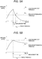
- the infusion state determination unit 58 determines whether the measurement time period T1 is longer than the period threshold T ⁇ . As illustrated in FIG. 5A , the determination result that the measurement time period T1 is shorter than the period threshold T ⁇ indicates a sudden decrease in the pressure value, and thus, this case is decided to be an extravasation phenomenon. Conversely, as illustrated in FIG. 5B , the determination result that the measurement time period T1 is longer than the period threshold T ⁇ indicates that the fluctuation of the pressure value is small, and thus, the case is decided to be not an extravasation phenomenon.
- the pressure determination threshold P ⁇ is set to 1/2 of the liquid delivery stop threshold Ps
- the pressure determination threshold P ⁇ is not limited to this value.
- the ratio of the pressure determination threshold P ⁇ to the liquid delivery stop threshold Ps is within a predetermined range, for example, 1/2 to 3/4, it is possible to detect the occurrence of an extravasation phenomenon during a relatively short time period.
- the setting of the period threshold T ⁇ depends on the setting of the pressure determination threshold P ⁇ , it would be preferable to set the period threshold T ⁇ to be in the range of a predetermined time period (seconds), for example, 10 seconds to 30 seconds, because this range enables satisfactory detection of the extravasation phenomenon without extending the stop period of liquid delivery.
- the determination method by the infusion state determination unit 58 is not limited to the above, and various modifications can be adopted.
- the infusion state determination unit 58 includes a period threshold T ⁇ and a pressure determination threshold P ⁇ , and a pressure value P at a point in time t2, at which the period threshold T ⁇ is passed from the point in time t0 of becoming the liquid delivery stop state, is compared with the pressure determination threshold P ⁇ .
- the pressure value P is the pressure determination threshold P ⁇ or below, the phenomenon is decided as an extravasation phenomenon, and in a case where the pressure value P is larger than the pressure determination threshold P ⁇ , the phenomenon is decided as not being the extravasation phenomenon.
- the infusion state detection system 10 can estimate whether the phenomenon is an extravasation phenomenon within a certain time period. This makes it possible to shorten the liquid delivery stop period.
- the infusion state determination unit 58 includes a pressure value change rate determination threshold RC, and performs a comparison with a change rate R3 for a predetermined point in time t3 that is passed from the point in time t0 of becoming the liquid delivery stop state. Subsequently, in a case where the change rate R3 is greater than the change rate determination threshold RC (in a case of abrupt decrease), it is decided that the phenomenon is an extravasation phenomenon, and in a case where the change rate R3 is smaller than the change rate determination threshold RC (in a case of gradual decrease), it is determined that it is not an extravasation phenomenon.
- the infusion state detection system 10 can also estimate whether the phenomenon is an extravasation phenomenon based on a waveform of a detected pressure value by determining using the change rate of the pressure value.
- the predetermined point in time t3 is not particularly limited, it is preferable to set to the value within a range of 30 seconds from the point in time t0. With this configuration, it is possible to shorten the liquid delivery stop period.
- the change rate calculation method may include calculation of performing differentiation at a point in time close to the point in time t0.
- the number of times (the number of points in time) to calculate the change rate is not particularly limited, and by performing a plurality of numbers of times, it is possible to achieve a higher determination accuracy.
- the infusion state determination unit 58 may determine the infusion state by combining a plurality of types of determination methods. This further enhances the determination accuracy.
- the infusion state determination unit 58 determines that the pressure increase is an extravasation phenomenon
- the infusion state determination unit 58 activates the alarm unit 62 and outputs an alarm indicating the occurrence of the extravasation phenomenon.
- the alarm output by the alarm unit 62 includes the alarm issued by various methods such as alarm sound and voice output.
- the control unit 54 may display the occurrence of the extravasation phenomenon using the display unit 28. In the display of the display unit 28, it is allowable to configure to perform guiding prompt of a necessary countermeasure for the extravasation phenomenon.
- control unit 54 continues to stop driving the liquid delivery unit 26 at the point in time of determining the extravasation phenomenon. This reduces the leakage of the medicinal solution L to the subcutaneous tissue of the patient C. Furthermore, the control unit 54 is preferably configured to communicate with a management server, or the like, in the hospital to inform about the occurrence of the abnormality (extravasation phenomenon) in the infusion.
- the infusion state determination unit 58 drives the liquid delivery unit 26 and restarts delivery of the medicinal solution L. Note that it is preferable to restart the delivery of the medicinal solution L at a point in time where the period threshold T ⁇ has passed, without waiting until the pressure value reaches the threshold P ⁇ for the pressure determination. With this configuration, it is possible to avoid prolongation of the liquid delivery stop state of the medicinal solution L.
- the infusion state determination unit 58 monitors the pressure value detected by the pressure sensor 40 even after the restart of delivery of the medicinal solution L. In a case where the pressure is not increased after the restart of the delivery of the liquid, the pressure increase at this point in time is estimated to be an increase phenomenon at a normal state, and delivery of the liquid medicinal solution L is continued.
- the pressure increase at this point in time is estimated to be an occlusion phenomenon. That is, re-increase of the pressure value can be considered to indicate that the inside of the infusion line 12 is occluded, substantially stopping the medicinal solution flow.
- the control unit 54 activates the alarm unit 62 and outputs an alarm, and then, stops driving the liquid delivery unit 26. This makes it possible to deal with the occlusion phenomenon of the infusion line 12 immediately. Note that the alarm for the occlusion phenomenon is different from the alarm for the extravasation phenomenon, thereby enabling the user to separately recognize the individual abnormalities.
- the threshold setting unit 60 of the control unit 54 includes a function of automatically setting the threshold pressure value Ps for stopping liquid delivery on the basis of the liquid delivery amount of the medicinal solution L. That is, in a case where the liquid delivery amount is small, the rate of increase of the pressure value detected by the pressure sensor 40 also decreases. Accordingly, the threshold setting unit 60 sets a low threshold pressure value Ps for stopping liquid delivery. For example, in a case where the liquid delivery amount is 1 mL/h, the threshold pressure value Ps for stopping liquid delivery is set to around 1.5 mmHg.
- the threshold setting unit 60 sets a high threshold Ps for stopping liquid delivery.
- the threshold pressure value Ps for stopping the liquid delivery is set to around 450 mmHg.
- the infusion state detection system 10 may be configured such that the user manually sets the threshold pressure value Ps for stopping liquid delivery.
- the infusion line 12 including the pressure sensor 40 is formed by the user, and thereafter, the control unit 54 starts driving together with power on of the liquid delivery pump 20. Subsequently, the liquid delivery amount of the medicinal solution L is set by the operation of the operation unit 30 by the user, and then, the threshold setting unit 60 automatically sets the threshold pressure value Ps for stopping liquid delivery. This completes preparation of the infusion state detection system 10 and the infusion line 12, and the control unit 54 starts a processing flow together with the start of the drive of the liquid delivery pump 20 (delivery of medicinal solution L).
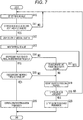
- control unit 54 receives a detection signal transmitted by the pressure sensor 40 by the pressure acquisition unit 56 and detects a pressure value at a position in the vicinity of the indwelling needle 18 (step S10).
- control unit 54 compares the detected pressure value with the threshold pressure value Ps set for stopping liquid delivery by the threshold setting unit 60 and determines whether the pressure value is the threshold pressure value Ps for stopping liquid delivery or above (step S11). In a case where the pressure value is lower than the threshold pressure value Ps for stopping liquid delivery, the processing returns to step S10 to monitor the pressure value at the point in time of delivery of the medicinal solution L. In a case where the pressure value is the threshold pressure value Ps for stopping liquid delivery or above, processing proceeds to step S12.
- step S12 the control unit 54 stops driving the liquid delivery unit 26 and stops delivery of the medicinal solution L.
- the control unit 54 measures the lapse of time from the point in time t0 at which the liquid delivery is stopped and monitors the pressure value of the pressure sensor 40 (step S13). Furthermore, during the stop period, the control unit 54 compares the pressure value with the threshold pressure value P ⁇ for pressure determination and determines whether the pressure value has reached the threshold pressure value P ⁇ for pressure determination (step S14). In a case where the pressure value has not reached the threshold pressure value P ⁇ for pressure determination, processing proceeds to step S17.
- the measurement time period T1 is calculated from the point in time t1, and it is determined whether the measurement time period T1 is the threshold T ⁇ for time period or below (step S15). In a case where the measurement time period T1 is the threshold T ⁇ for time period or below, the processing proceeds to step S16. In a case where the measurement time period T1 is greater than the threshold T ⁇ for time period, processing proceeds to step S18.
- step S16 the control unit 54 decides that an extravasation phenomenon has occurred, and outputs an alarm for the extravasation phenomenon by the alarm unit 62. Moreover, the control unit 54 continues to stop driving the liquid delivery unit 26.
- the measurement time period T1 is calculated in step S17 from the point in time t1 as in step S15, and it is determined whether the measurement time period T1 the threshold T ⁇ for time period or below. In a case where the measurement time period T1 is the threshold T ⁇ for a time period, processing returns to step S14. In a case where the measurement time period T1 is greater than the threshold T ⁇ for a time period, processing proceeds to step S18.
- step S18 the control unit 54 decides that no extravasation phenomenon has occurred and ends the stop period, and then, restarts the delivery of the medicinal solution L by the liquid delivery unit 26. At this point in time, the control unit 54 continues acquisition of the pressure value.
- the control unit 54 determines whether the pressure value is increasing (that is, whether it is decreasing or constant) (step S19). In a case where the pressure value is increasing, the control unit 54 estimates that the occlusion phenomenon has occurred and proceeds to step S20. In contrast, in a case where the pressure value is decreased or constant, the control unit 54 estimates the occurrence of an increase phenomenon at a normal state and returns to step S10, and then, continues the delivery of the medicinal solution L and the monitoring of the pressure inside the infusion line 12.
- step S20 the control unit 54 outputs an alarm for occlusion phenomenon by the alarm unit 62. Moreover, the control unit 54 stops driving the liquid delivery unit 26 and stops delivery of the medicinal solution L again. Subsequently, the infusion state detection system 10 finishes this processing flow based on operation by the user after outputting the alarm or during infusion.
- the infusion state detection system 10 can satisfactorily estimate the extravasation phenomenon by detecting a sudden decrease in the pressure value during the stop period of the liquid delivery pump 20. Therefore, notification of the occurrence of the extravasation phenomenon to the user by the control unit 54 enables the user to take necessary countermeasures at an early stage. As a result, the infusion state detection system 10 achieves higher reliability of detection and further enhances the usability. Moreover, as a result of this determination processing, it is possible to quantitatively deliver the liquid without changing the liquid delivery amount of the medicinal solution L during infusion, leading to facilitated liquid supply control.
- the control unit 54 measures the time period at which the pressure value inside the infusion line 12 during the stop period reaches a value of the pressure determination threshold or below, thereby detecting the extravasation phenomenon satisfactorily in a case where the measurement time period T1 is the threshold T ⁇ for time period T ⁇ or below. Moreover, in a case where the pressure value increases after restarting the drive of the liquid delivery pump 20, the control unit 54 can estimate that an occlusion phenomenon is occurring. Accordingly, the user can receive a notification of the occurrence of the occlusion phenomenon from the liquid delivery pump 20 and can take necessary measures at an early stage.
- the pressure sensor 40 is arranged at a position in vicinity of the indwelling needle 18 (insertion section) of the infusion line 12, thereby detecting the pressure value inside the infusion line 12 near the indwelling needle 18.
- the control unit 54 automatically sets the threshold pressure value Ps for stopping liquid delivery on the basis of the liquid delivery amount of the medicinal solution L, it is possible to monitor the pressure change according to the liquid delivery amount, leading to further enhancement of the usability of the infusion state detection system 10.
- estimation of the occlusion phenomenon by the control unit 54 may also use the change rate until the pressure value increases to reach the threshold pressure value Ps for stopping liquid delivery regardless of the pressure value after restarting delivery of the medicinal solution.
- occurrence of occlusion inside the infusion line 12 hinders flow of the medicinal solution L and thus, the pressure value increases relatively suddenly.
- the control unit 54 can satisfactorily determine the occlusion phenomenon based on the change rate (rate of increase) of the pressure value.
- control unit 54 may estimate the infusion state inside the infusion line 12 by using the pump-side pressure detector 38 and the pressure sensor 40 in combination. That is, in a case where there is a significant difference in a change in the pressure value between the pump-side pressure detector 38 and the pressure sensor 40, it is possible to estimate the occurrence of the occlusion phenomenon of the tube 16.
- the pressure value of the pressure sensor 40 may be used for determination of the extravasation phenomenon
- the pressure value of the pump-side pressure detector 38 may be used for determination of the occlusion phenomenon.
- FIG. 4A is a diagrammatic representation of FIG. 4A
Landscapes
- Health & Medical Sciences (AREA)
- Vascular Medicine (AREA)
- Engineering & Computer Science (AREA)
- Anesthesiology (AREA)
- Biomedical Technology (AREA)
- Heart & Thoracic Surgery (AREA)
- Hematology (AREA)
- Life Sciences & Earth Sciences (AREA)
- Animal Behavior & Ethology (AREA)
- General Health & Medical Sciences (AREA)
- Public Health (AREA)
- Veterinary Medicine (AREA)
- Infusion, Injection, And Reservoir Apparatuses (AREA)
Abstract
Description
- The present invention relates to an infusion state detection system configured to detect an abnormality in an infusion state when a liquid such as a medicinal solution is delivered using an infusion line.
- The infusion line is formed by connecting an infusion set such as a medical bag, a tube, and an indwelling needle, for treatment of continuously administering a medicinal solution to a patient with an arbitrary supply amount. This type of treatment requires ensured conduction in the infusion line and stable delivery of the medicinal solution. Generally, an infusion pump includes a pressure sensor for detecting the pressure in the infusion line and an abnormality (occurrence of occlusion) of a conduction state in the infusion line is detected on the basis of a pressure value detected by the sensor.
- Meanwhile, potential adverse events during infusion include an extravasation, that is, leakage of the medicinal solution into the subcutaneous tissue between the blood vessel and the epidermis as a result of a dislocated indwelling needle of the infusion line from the blood vessel into which the needle is inserted. In this case, even though the pressure inside the infusion line increases because the medicinal solution is pushed into the subcutaneous tissue, this degree of increase is smaller than a case where the infusion line is completely occluded, and thus, it is difficult to detect the increase with a sensor attached to the infusion pump in many cases. Moreover, there may be a case where the pressure increase due to extravasation is substantially equal to the degree of a pressure change induced by a posture change (standing up, etc.) of the patient, venous pressure fluctuation, or the like. Therefore, it is difficult to determine the infusion state merely by monitoring the pressure in the infusion line during infusion. This leads to an unfavorable case, in the infusion state detection system, where reliability of detection is decreased due to an occurrence of misreporting, overlooking of the extravasation, or the like.
- As a technique for solving these problems, a system disclosed in
JP 3551974 B - In the system disclosed in
JP 3551974 B - The present invention is made in view of the above circumstances, and is intended to provide an infusion state detection system capable of at a constant flow rate delivering liquid during infusion, and capable of determining the infusion state with high accuracy, thereby achieving higher reliability of detection with further enhanced usability.
- In order to achieve the above-described intention, the infusion state detection system according to the present invention includes: a pump unit configured to deliver a liquid in an infusion line; a pressure detector arranged in the infusion line and configured to detect a pressure in the infusion line; and a determination processing unit configured to stop driving of the pump unit and determine an infusion state on the basis of a pressure value detected by the pressure detector during a stop period, in a case where the pressure value of the pressure detector becomes a set pressure or above.
- According to the above, the infusion state detection system can determine, with high accuracy, the infusion state using the pressure value of the pressure detector during the stop period of the pump unit. That is, the determination processing unit can satisfactorily estimate the leakage of the liquid to the outside of a living body lumen by detecting a sudden decrease in the pressure value during the liquid delivery stop period. With this configuration, the user can take necessary countermeasures at an early stage by receiving notification of the occurrence of liquid leakage. As a result, the infusion state detection system can achieve higher reliability of detection and further enhance usability. Moreover, with such a determination, it is possible to deliver, at a constant flow rate, the medicinal solution during the infusion, making it easier to control the supply of the liquid and to register the infusion state.
- In this case, the determination processing unit preferably measures a time period at which the pressure value inside the infusion line during the stop period is a predetermined ratio of the set pressure or below, and preferably decides that the leakage of the liquid to the outside of the living body lumen has occurred in a case where the measured time period is a predetermined period threshold or below.
- That is, the liquid leakage to the outside of the living body lumen would lead to continuous discharge of the liquid, and this leads to sudden decrease in the pressure value during the stop period. Accordingly, the time period measured by the determination processing unit is compared with the period threshold, and in a case where the measured time period is the predetermined period threshold or below, it is possible to satisfactorily detect the leakage of the liquid to the outside of the living body lumen.
- Alternatively, the determination processing unit may decide that the leakage of the liquid to the outside of the living body lumen has occurred in a case where the pressure value at the point in time when a predetermined period threshold is passed from the point in time of becoming the liquid delivery stop state is a predetermined pressure determination threshold or below.
- In this manner, by comparing, by the determination processing unit, the pressure value at the point in time when a predetermined period threshold is passed from the point in time of becoming the liquid delivery stop state, with the pressure determination threshold, it is also possible to satisfactorily detect leakage of the liquid to the outside of the living body lumen.
- Alternatively, the determination processing unit may be configured to decide that the leakage of the liquid to the outside of the living body lumen has occurred in case where a change rate of the pressure value in the infusion line during the stop period is a predetermined change rate threshold or above.
- In this manner, it is also possible to reliably detect leakage of the liquid to the outside of the living body lumen by comparing, by the determination processing unit, the change rate of the pressure value in the infusion line during the stop period with the change rate threshold.
- Moreover, the determination processing unit preferably decides that occlusion of the infusion line has occurred in a case where driving of the pump unit is restarted after the end of the stop period and the pressure value detected by the pressure detector increases after the restart.
- In this manner, it is possible to estimate the occurrence of occlusion in the infusion line in a case where the pressure value detected by the pressure detector increases after the restart of driving of the pump unit. With this configuration, the user can take necessary countermeasures at an early stage by receiving notification of the occurrence of occlusion of the infusion line.
- Furthermore, the pressure detector is preferably arranged at a position in the vicinity of an insertion section of the infusion line to be inserted into the living body.
- By arranging the pressure detector at a position in the vicinity of the insertion section of the infusion line in this manner, it is possible to detect the pressure value in the infusion line near the insertion section, leading to achieving determination of the infusion state by the determination processing unit with higher accuracy.
- Furthermore, the determination processing unit is preferably configured to automatically set the set pressure on the basis of the liquid delivery amount of the pump unit.
- With the configuration, in which the determination processing unit automatically sets the set pressure on the basis of the liquid delivery amount in this manner, it is possible to monitor the pressure change according to the liquid delivery amount, leading to further enhancement of the usability of the infusion state detection system.
- According to the present invention, the infusion state detection system can, at a constant flow rate, deliver the liquid in the infusion line and can determine the infusion state with high accuracy, thereby achieving higher reliability of the detection and further enhancing the usability.
-
-
FIG. 1 is a diagram schematically illustrating an overall configuration of a liquid infusion state detection system according to an embodiment of the present invention. -
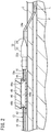
FIG. 2 is a partial sectional side view schematically illustrating a downstream side of the infusion line ofFIG. 1 . -
FIG. 3 is an occlusion diagram illustrating a functional unit of the infusion state detection system ofFIG. 1 . -
FIG. 4A is a diagram schematically illustrating an extravasation phenomenon, andFIG. 4B is a diagram schematically illustrating an occlusion phenomenon. -
FIG. 5A is a graph illustrating a pressure value change at the point in time of occurrence of an extravasation phenomenon and a method for determination by a control unit, andFIG. 5B is a graph illustrating a pressure value change in another phenomenon and a method for determination by the control unit. -
FIG. 6A is a graph illustrating a method for determining an extravasation phenomenon by the control unit according to a first modification, andFIG. 6B is a graph illustrating a method for determining an extravasation phenomenon by the control unit according to a second modification. -
FIG. 7 is a flowchart illustrating a processing flow of the control unit of the infusion state detection system inFIG. 1 . - Hereinafter, preferred embodiments of the infusion state detection system according to the present invention will be described in detail with reference to the accompanying drawings.
- An infusion
state detection system 10 according to one embodiment of the present invention is applied to aninfusion line 12 connected to the inside of the body of a patient C from amedical bag 14, as illustrated inFIG. 1 . The infusionstate detection system 10 is configured to determine an infusion state by detecting a pressure of a medicinal solution L (liquid) flowing inside of theinfusion line 12. The infusionstate detection system 10 continues infusion in a case where the infusion state is normal and gives warning to a medical practitioner, or the like, in a case where the infusion state is abnormal. - The
infusion line 12, to which the infusionstate detection system 10 is applied, forms a flow path of the medicinal solution L to the patient C, and its components are not limited.FIG. 1 illustrates a representative case including themedical bag 14, atube 16, an indwelling needle 18 (cannula) and a liquid delivery pump 20 (pump unit). Theinfusion line 12 may additionally include a drip tube, a klemme (clamp), a filter, a connector for connecting anothertube 16. Moreover, the infusionstate detection system 10 and theinfusion line 12 may be provided collectively as an infusion set (product), or may be formed by arbitrarily combining components by the medical practitioner. - The
medical bag 14 is formed in a bag shape by blow molding, or the like, using a thermoplastic resin material having flexibility and chemical resistance, and stores a predetermined amount of the medicinal solution L in aninternal storage space 14a. One end of thetube 16 is connected to a lower end of themedical bag 14 via a needle for piercing a seal of a bottle (not illustrated), or the like. The medicinal solution L is discharged from thestorage space 14a to thetube 16, thereby flowing inside thetube 16. - The medicinal solution L applied to the infusion solution is not particularly limited, and an appropriate one may be selected according to the disease or treatment details of the patient C. Examples of the medicinal solution L include an anticancer agent, an anesthetic agent, and a chemotherapeutic agent. Alternatively, the
infusion line 12 may also be configured to deliver a liquid such as blood and a nutritional supplement other than the medicinal solution L. - The
tube 16 is formed by injection molding from a thermoplastic resin material having flexibility and chemical resistance, and internally includes aconduit 16a for the medicinal solution L. In construction of theinfusion line 12, thetube 16 is appropriately selected to have a sufficient length to connect from themedical bag 14 to the body surface of the patient C, with a margin. Theinfusion line 12 may be formed by connecting a plurality oftubes 16. - The indwelling
needle 18 is connected to an end of thetube 16 on the side opposite to themedical bag 14. As illustrated inFIG. 2 , for example, the indwellingneedle 18 includes ahub 22 functioning as a connector with thetube 16, and a smalloutside diameter tube 24 connected to thehub 22. Thehub 22 is formed of a material harder than thetube 16, and internally includes ahollow portion 22a that communicates with theconduit 16a. - The small
outside diameter tube 24 is formed of a flexible resin material and includes adischarge passage 24a communicating with thehollow portion 22a. The smalloutside diameter tube 24 is inserted into a blood vessel V (a vein as a living body lumen) from the body surface of the patient C together with a puncture needle (not illustrated) and is placed in the blood vessel V by removing the puncture needle. After being placed in the blood vessel V, the smalloutside diameter tube 24 allows the medicinal solution L to flow into the blood vessel V from a distal end opening of the tube via thedischarge passage 24a. That is, theinfusion line 12 includes thestorage space 14a, theconduit 16a, thehollow portion 22a, and thedischarge passage 24a as flow spaces for the medicinal solution L beginning from themedical bag 14 to the patient C. In the present description, these flow spaces are collectively referred to as the inside of theinfusion line 12. - Returning to
FIG. 1 , theliquid delivery pump 20 is provided at a position in the middle of thetube 16 and includes a function of delivering the medicinal solution L at a constant flow rate into the blood vessel V. Theliquid delivery pump 20 includes aliquid delivery unit 26 that houses a portion of thetube 16 to deliver the medicinal solution L, adisplay unit 28 that displays the display information necessary for delivering the medicinal solution L, and anoperation unit 30 by which the medical practitioner operates theliquid delivery pump 20. - The
liquid delivery unit 26 includes amain body unit 32 and acover 34 and is configured such that thetube 16 can be set in themain body unit 32 in a state where thecover 34 is open. Themain body unit 32 includes a groove (not illustrated) in which thetube 16 is arranged and a squeezingmechanism 36 is provided in this groove to squeeze the arrangedtube 16. The squeezingmechanism 36 is formed with a plurality of pressing members (fingers in a case of a peristaltic type) and a plurality of rollers (not illustrated) (in a case of a roller type), for example, and sequentially presses thetube 16 from the upstream side toward the downstream side, thereby allowing the medicinal solution L present in theconduit 16a to flow toward the downstream side. Theliquid delivery unit 26 delivers the medicinal solution L in theconduit 16a in the range of 0 mL to 999 mL, for example. Note that 0 mL is in the liquid delivery stop state. - The
display unit 28 is a monitor that displays the liquid delivery amount of the medicinal solution L set by the user (medical practitioner, such as a doctor or a nurse) or displays the liquid delivery amount of the medicinal solution L being actually delivered. Thedisplay unit 28 is formed with a liquid crystal display, for example. Thedisplay unit 28 also functions as the infusionstate detection system 10 and displays the pressure inside theinfusion line 12 detected during infusion, for example. Moreover, thedisplay unit 28 may be configured to display a warning in a case where an abnormality occurs in the infusion state. - The
operation unit 30 is formed with a plurality of buttons and is capable of executing power on/off switching of theliquid delivery pump 20, drive start/stop switching of theliquid delivery pump 20, numerical changeover, setting, etc. of the liquid delivery amount, or the like. - Moreover, as illustrated in
FIG. 3 , theliquid delivery pump 20 internally includes a pump-side pressure detector 38 configured to detect the pressure in theconduit 16a of thetube 16. The pump-side pressure detector 38 detects the pressure in theconduit 16a in theliquid delivery pump 20. The infusionstate detection system 10 according to the present embodiment performs specific determination by detecting the pressure using two pressure detectors, that is, the pump-side pressure detector 38 and apressure sensor 40 to be described below. Note that the infusionstate detection system 10 may of course detect the pressure inside theinfusion line 12 with solely any one of the pump-side pressure detector 38 and thepressure sensor 40. - Returning to
FIG. 1 , the infusionstate detection system 10 according to the present embodiment is formed by providing thepressure sensor 40 on theinfusion line 12 and using the above-describedliquid delivery pump 20. - The
pressure sensor 40 is provided on thetube 16 close to the indwellingneedle 18 in order to detect the pressure inside theinfusion line 12 in the vicinity of the discharge position of the medicinal solution L. Thepressure sensor 40 includes a disk shape, one surface thereof being fixed to the body surface of the patient C. For example, as illustrated inFIG. 2 , thepressure sensor 40 includes acase 44 and ameasurement unit 46. Thecase 44 is attached to the body surface via atape 42. Themeasurement unit 46 closes an opening surface of ameasurement chamber 44a of thecase 44 and measures the pressure inside themeasurement chamber 44a. - The
case 44 includes ameasurement chamber 44a, aninflow port 44b and anoutflow port 44c. Theinflow port 44b communicates with themeasurement chamber 44a and is connected to thetube 16 on the upstream side. Theoutflow port 44c communicates with themeasurement chamber 44a and is connected to thetube 16 on the downstream side. Themeasurement chamber 44a temporarily stores (at a low liquid pressure) the medicinal solution L flowing in from theinflow port 44b in the normal state of infusion fluid and allows the medicinal solution L to flow out of theoutflow port 44c. Themeasurement chamber 44a, theinflow port 44b, and theoutflow port 44c may be configured as a single conduit. - The
measurement unit 46 includes adiaphragm 48 on an opposing surface of themeasurement chamber 44a and detects the pressure of the medicinal solution L that has flown into themeasurement chamber 44a. That is, themeasurement unit 46 detects a low pressure in a case where thediaphragm 48 is hardly deformed in the normal state of the infusion and detects a high pressure in a case where thediaphragm 48 is expanded due to an abnormality in the infusion. Moreover, themeasurement unit 46 includes a sensor-side communication unit 50 and a battery 52 (refer toFIG. 3 ), and wirelessly transmits a pressure detection signal to theliquid delivery pump 20 via the sensor-side communication unit 50. - As illustrated in
FIG. 3 , the infusionstate detection system 10 controls an entire system by acontrol unit 54 provided in theliquid delivery pump 20. Basically, thecontrol unit 54 controls theliquid delivery unit 26 to deliver the medicinal solution L. Thecontrol unit 54 is formed with a known computer (a microcomputer, or the like) including an arithmetic processing unit, a storage unit, and an input/output unit (not illustrated). Thecontrol unit 54 drives the squeezingmechanism 36 on the basis of the liquid delivery amount set by the user via theoperation unit 30 and delivers the medicinal solution L in thetube 16. - By executing a program of the infusion
state detection system 10, thecontrol unit 54 serves as a determination processing unit for determining whether the infusion state is normal or abnormal. More specifically, thecontrol unit 54 internally includes apressure acquisition unit 56, an infusionstate determination unit 58, and athreshold setting unit 60 provided by executing a program. Moreover, analarm unit 62 is provided in advance in theliquid delivery pump 20 as a functional unit of the infusionstate detection system 10. - The
pressure acquisition unit 56 is a functional unit that receives a detection signal of thepressure sensor 40 periodically (or by sending a transmission instruction to the pressure sensor 40) and processes this detection signal to obtain a pressure value. Thepressure acquisition unit 56 wirelessly receives a detection signal from the sensor-side communication unit 50 by the pump-side communication unit 64 provided in theliquid delivery pump 20. With this configuration, it is possible, in the infusionstate detection system 10, to reduce the number of electrical wiring and reduce the work burden at the time of construction of theinfusion line 12. Together with this, it is possible to facilitate operation of the patient C even during infusion. Thepressure sensor 40 and thecontrol unit 54 may communicate with each other by wire, of course. - On the basis of the pressure value obtained by the
pressure acquisition unit 56, the infusionstate determination unit 58 determines whether the infusion state is normal or abnormal. Hereinafter, a principle of determination of the infusion state by the infusionstate determination unit 58 will be described. - In the normal state, the
infusion line 12 discharges the medicinal solution L from the smalloutside diameter tube 24 of the indwellingneedle 18 inserted into the blood vessel V and allows the medicinal solution L to flow in the blood vessel V (also refer toFIG. 2 ). In theinfusion line 12, however, as described above, the pressure inside theinfusion line 12 might increase due to a blood pressure change by a change in the posture of the patient C, a change in venous pressure, or the like (hereinafter, this will be referred to as an increase phenomenon at a normal state). - Moreover, in the
infusion line 12, there might be a case where a physical trouble occurs in theinfusion line 12 due to some cause during the infusion (for example, physical movement of the patient C, a force acting on thetube 16 and the indwelling needle 18) resulting in a failure of supplying the medicinal solution L normally to the inside of the blood vessel V of the patient C. For example, as illustrated inFIG. 4A , there is a possibility that the tip of the indwellingneedle 18 comes out of the blood vessel V and is positioned in the subcutaneous tissue and supplies, in this state, the medicinal solution L (hereinafter referred to as "extravasation phenomenon"). In this case, although the medicinal solution L flows somewhat, the flow of the medicinal solution L is less smooth compared to the normal state. Even in such a state, theliquid delivery pump 20 delivers the liquid at a constant flow rate, and the medicinal solution L partially accumulates inside theinfusion line 12. This increases the pressure inside theinfusion line 12 until the pressure reaches a pressure needed to carry the medicinal solution L at a flow rate delivered from theliquid delivery pump 20 to the inside of theinfusion line 12 that has difficulty in achieving a smooth flow. This leads to an increase in the pressure in themeasurement chamber 44a of thepressure sensor 40. - Moreover, for example, as illustrated in
FIG. 4B , there is a possibility that the middle portion of the indwellingneedle 18 and thetube 16 are kinked, and the inside of theinfusion line 12 is occluded (hereinafter referred to as an occlusion phenomenon). In this case, theconduit 16a and thedischarge passage 24a are substantially occluded, prohibiting the flow of the medicinal solution L. Therefore, the medicinal solution L delivered from theliquid delivery pump 20 accumulates inside theinfusion line 12, increasing the pressure inside theinfusion line 12. This also increases the pressure in themeasurement chamber 44a of thepressure sensor 40. - The infusion
state determination unit 58 determines whether the infusion state is normal or abnormal in a case where the pressure in themeasurement chamber 44a increases due to a plurality of types of causes as described above. Specifically, the threshold Ps (set pressure) for stopping liquid delivery is stored in advance in the storage unit, and the pressure value obtained by thepressure acquisition unit 56 is compared with the liquid delivery stop threshold Ps, during the infusion. Subsequently, when the pressure value becomes the liquid delivery stop threshold Ps or above, the driving of theliquid delivery unit 26 is stopped and processing of stopping the delivery of the medicinal solution L inside theinfusion line 12 is performed (hereinafter referred to as a liquid delivery stop state). - In this manner, in a case where the
liquid delivery pump 20 stops delivering the medicinal solution L, the pressure changes in themeasurement chamber 44a. The infusionstate determination unit 58 distinguishes between the extravasation phenomenon, and other normal state increase phenomenon or occlusion phenomenon, on the basis of the fluctuation of the pressure value during implementation of the liquid delivery stop state (during the liquid delivery stop period). - Specifically, as illustrated in
FIG. 5A , in a case where an extravasation phenomenon occurs in theinfusion line 12, the pressure value demonstrates a reaction of a relatively sudden decrease in the liquid delivery stop state. In the case of the extravasation phenomenon, the medicinal solution L flows to the outside of theinfusion line 12 although the resistance is high. Accordingly, when the liquid is not delivered from theliquid delivery pump 20, the medicinal solution L accumulated in theinfusion line 12 continues to flow out to the subcutaneous tissue on the downstream side of thepressure sensor 40, and the pressure value decreases during a short time period. - In contrast, in a case where an occlusion phenomenon occurs, the medicinal solution L continuously remains in the
infusion line 12 even after the stoppage of the liquid delivery from theliquid delivery pump 20. Therefore, the pressure inside theinfusion line 12 does not change in principle, but the pressure might gradually decrease due to the flexibility of thetube 16. As illustrated inFIG. 5B , the degree of the pressure decrease at this time is more gradual compared to the case of the extravasation phenomenon illustrated inFIG. 5A . Moreover, in a case of normal administration, there is substantially no pressure increase due to liquid delivery, and the reason for the increase in the pressure inside theinfusion line 12 is due to the blood pressure of the patient. That is, in the case of an increase phenomenon at a normal state , the cause is a change in the blood pressure of the patient C, and thus, the pressure inside theinfusion line 12 does not change even when the liquid delivery is stopped. - Accordingly, the infusion
state determination unit 58 can estimate the occurrence of the extravasation phenomenon by monitoring the change in the pressure value after the liquid delivery stop state. Specifically, as illustrated inFIG. 5A , the infusionstate determination unit 58 includes a pressure determination threshold Pα set to a predetermined ratio with respect to the liquid delivery stop threshold Ps, and a preset period threshold Tα. The infusionstate determination unit 58 starts measuring the time period from the point in time t0 of becoming the liquid delivery stop state and calculates a measurement time period T1 up to the point in time t1 at which the pressure value reaches the pressure determination threshold Pα. - After calculating the measurement time period T1, the infusion
state determination unit 58 determines whether the measurement time period T1 is longer than the period threshold Tα. As illustrated inFIG. 5A , the determination result that the measurement time period T1 is shorter than the period threshold Tα indicates a sudden decrease in the pressure value, and thus, this case is decided to be an extravasation phenomenon. Conversely, as illustrated inFIG. 5B , the determination result that the measurement time period T1 is longer than the period threshold Tα indicates that the fluctuation of the pressure value is small, and thus, the case is decided to be not an extravasation phenomenon. - While, in the present embodiment, the pressure determination threshold Pα is set to 1/2 of the liquid delivery stop threshold Ps, the pressure determination threshold Pα is not limited to this value. For example, in a case where the ratio of the pressure determination threshold Pα to the liquid delivery stop threshold Ps is within a predetermined range, for example, 1/2 to 3/4, it is possible to detect the occurrence of an extravasation phenomenon during a relatively short time period. While the setting of the period threshold Tα depends on the setting of the pressure determination threshold Pα, it would be preferable to set the period threshold Tα to be in the range of a predetermined time period (seconds), for example, 10 seconds to 30 seconds, because this range enables satisfactory detection of the extravasation phenomenon without extending the stop period of liquid delivery.
- The determination method by the infusion
state determination unit 58 is not limited to the above, and various modifications can be adopted. For example, as illustrated inFIG. 6A , it is allowable to configure such that the infusionstate determination unit 58 includes a period threshold Tβ and a pressure determination threshold Pβ, and a pressure value P at a point in time t2, at which the period threshold Tβ is passed from the point in time t0 of becoming the liquid delivery stop state, is compared with the pressure determination threshold Pβ. In a case where the pressure value P is the pressure determination threshold Pβ or below, the phenomenon is decided as an extravasation phenomenon, and in a case where the pressure value P is larger than the pressure determination threshold Pβ, the phenomenon is decided as not being the extravasation phenomenon. - In this manner, by using the pressure value P at the period threshold Tβ, the infusion
state detection system 10 can estimate whether the phenomenon is an extravasation phenomenon within a certain time period. This makes it possible to shorten the liquid delivery stop period. - Moreover, for example, as illustrated in
FIG. 6B , it is allowable to configure such that the infusionstate determination unit 58 includes a pressure value change rate determination threshold RC, and performs a comparison with a change rate R3 for a predetermined point in time t3 that is passed from the point in time t0 of becoming the liquid delivery stop state. Subsequently, in a case where the change rate R3 is greater than the change rate determination threshold RC (in a case of abrupt decrease), it is decided that the phenomenon is an extravasation phenomenon, and in a case where the change rate R3 is smaller than the change rate determination threshold RC (in a case of gradual decrease), it is determined that it is not an extravasation phenomenon. - In this manner, the infusion
state detection system 10 can also estimate whether the phenomenon is an extravasation phenomenon based on a waveform of a detected pressure value by determining using the change rate of the pressure value. While the predetermined point in time t3 is not particularly limited, it is preferable to set to the value within a range of 30 seconds from the point in time t0. With this configuration, it is possible to shorten the liquid delivery stop period. In addition to the calculation based on the individual pressure values at the point in time t0 and the point in time t3, the change rate calculation method may include calculation of performing differentiation at a point in time close to the point in time t0. Moreover, the number of times (the number of points in time) to calculate the change rate is not particularly limited, and by performing a plurality of numbers of times, it is possible to achieve a higher determination accuracy. - Moreover, other than performing one type of the above-described determination method, the infusion
state determination unit 58 may determine the infusion state by combining a plurality of types of determination methods. This further enhances the determination accuracy. - Returning to
FIG. 3 , in a case where the infusionstate determination unit 58 determines that the pressure increase is an extravasation phenomenon, the infusionstate determination unit 58 activates thealarm unit 62 and outputs an alarm indicating the occurrence of the extravasation phenomenon. The alarm output by thealarm unit 62 includes the alarm issued by various methods such as alarm sound and voice output. Alternatively, thecontrol unit 54 may display the occurrence of the extravasation phenomenon using thedisplay unit 28. In the display of thedisplay unit 28, it is allowable to configure to perform guiding prompt of a necessary countermeasure for the extravasation phenomenon. - Moreover, the
control unit 54 continues to stop driving theliquid delivery unit 26 at the point in time of determining the extravasation phenomenon. This reduces the leakage of the medicinal solution L to the subcutaneous tissue of the patient C. Furthermore, thecontrol unit 54 is preferably configured to communicate with a management server, or the like, in the hospital to inform about the occurrence of the abnormality (extravasation phenomenon) in the infusion. - Moreover, in a case where the infusion
state determination unit 58 determines that the pressure increase is not an extravasation phenomenon, the infusionstate determination unit 58 drives theliquid delivery unit 26 and restarts delivery of the medicinal solution L. Note that it is preferable to restart the delivery of the medicinal solution L at a point in time where the period threshold Tα has passed, without waiting until the pressure value reaches the threshold Pα for the pressure determination. With this configuration, it is possible to avoid prolongation of the liquid delivery stop state of the medicinal solution L. - The infusion
state determination unit 58 monitors the pressure value detected by thepressure sensor 40 even after the restart of delivery of the medicinal solution L. In a case where the pressure is not increased after the restart of the delivery of the liquid, the pressure increase at this point in time is estimated to be an increase phenomenon at a normal state, and delivery of the liquid medicinal solution L is continued. - In contrast, in a case where the pressure value increases again with the restart of liquid delivery, the pressure increase at this point in time is estimated to be an occlusion phenomenon. That is, re-increase of the pressure value can be considered to indicate that the inside of the
infusion line 12 is occluded, substantially stopping the medicinal solution flow. In a case where the occlusion phenomenon is estimated, thecontrol unit 54 activates thealarm unit 62 and outputs an alarm, and then, stops driving theliquid delivery unit 26. This makes it possible to deal with the occlusion phenomenon of theinfusion line 12 immediately. Note that the alarm for the occlusion phenomenon is different from the alarm for the extravasation phenomenon, thereby enabling the user to separately recognize the individual abnormalities. - Moreover, the
threshold setting unit 60 of thecontrol unit 54 includes a function of automatically setting the threshold pressure value Ps for stopping liquid delivery on the basis of the liquid delivery amount of the medicinal solution L. That is, in a case where the liquid delivery amount is small, the rate of increase of the pressure value detected by thepressure sensor 40 also decreases. Accordingly, thethreshold setting unit 60 sets a low threshold pressure value Ps for stopping liquid delivery. For example, in a case where the liquid delivery amount is 1 mL/h, the threshold pressure value Ps for stopping liquid delivery is set to around 1.5 mmHg. - Conversely, in a case where the liquid delivery amount is large, the rate of increase of the pressure value detected by the
pressure sensor 40 also increases. Accordingly, thethreshold setting unit 60 sets a high threshold Ps for stopping liquid delivery. For example, in a case where the liquid delivery amount is 500 mL/h, the threshold pressure value Ps for stopping the liquid delivery is set to around 450 mmHg. Of course, the infusionstate detection system 10 may be configured such that the user manually sets the threshold pressure value Ps for stopping liquid delivery. - Following the above description on the basic configuration of the infusion
state detection system 10 according to the present embodiment, operation and effect thereof will be described below with reference to the flowchart ofFIG. 7 . - In the infusion
state detection system 10, theinfusion line 12 including thepressure sensor 40 is formed by the user, and thereafter, thecontrol unit 54 starts driving together with power on of theliquid delivery pump 20. Subsequently, the liquid delivery amount of the medicinal solution L is set by the operation of theoperation unit 30 by the user, and then, thethreshold setting unit 60 automatically sets the threshold pressure value Ps for stopping liquid delivery. This completes preparation of the infusionstate detection system 10 and theinfusion line 12, and thecontrol unit 54 starts a processing flow together with the start of the drive of the liquid delivery pump 20 (delivery of medicinal solution L). - After starting the processing flow, the
control unit 54 receives a detection signal transmitted by thepressure sensor 40 by thepressure acquisition unit 56 and detects a pressure value at a position in the vicinity of the indwelling needle 18 (step S10). - Subsequently, the
control unit 54 compares the detected pressure value with the threshold pressure value Ps set for stopping liquid delivery by thethreshold setting unit 60 and determines whether the pressure value is the threshold pressure value Ps for stopping liquid delivery or above (step S11). In a case where the pressure value is lower than the threshold pressure value Ps for stopping liquid delivery, the processing returns to step S10 to monitor the pressure value at the point in time of delivery of the medicinal solution L. In a case where the pressure value is the threshold pressure value Ps for stopping liquid delivery or above, processing proceeds to step S12. - In step S12, the
control unit 54 stops driving theliquid delivery unit 26 and stops delivery of the medicinal solution L. During this stop period, thecontrol unit 54 measures the lapse of time from the point in time t0 at which the liquid delivery is stopped and monitors the pressure value of the pressure sensor 40 (step S13). Furthermore, during the stop period, thecontrol unit 54 compares the pressure value with the threshold pressure value Pα for pressure determination and determines whether the pressure value has reached the threshold pressure value Pα for pressure determination (step S14). In a case where the pressure value has not reached the threshold pressure value Pα for pressure determination, processing proceeds to step S17. - In a case where the pressure value has reached the threshold pressure value Pα for pressure determination in step S14, the measurement time period T1 is calculated from the point in time t1, and it is determined whether the measurement time period T1 is the threshold Tα for time period or below (step S15). In a case where the measurement time period T1 is the threshold Tα for time period or below, the processing proceeds to step S16. In a case where the measurement time period T1 is greater than the threshold Tα for time period, processing proceeds to step S18.
- In step S16, the
control unit 54 decides that an extravasation phenomenon has occurred, and outputs an alarm for the extravasation phenomenon by thealarm unit 62. Moreover, thecontrol unit 54 continues to stop driving theliquid delivery unit 26. - In contrast, in a case where the pressure value has not reached the threshold pressure value Pα for the pressure determination in step S14, the measurement time period T1 is calculated in step S17 from the point in time t1 as in step S15, and it is determined whether the measurement time period T1 the threshold Tα for time period or below. In a case where the measurement time period T1 is the threshold Tα for a time period, processing returns to step S14. In a case where the measurement time period T1 is greater than the threshold Tα for a time period, processing proceeds to step S18.
- In step S18, the
control unit 54 decides that no extravasation phenomenon has occurred and ends the stop period, and then, restarts the delivery of the medicinal solution L by theliquid delivery unit 26. At this point in time, thecontrol unit 54 continues acquisition of the pressure value. - Subsequently, after restarting the liquid delivery, the
control unit 54 determines whether the pressure value is increasing (that is, whether it is decreasing or constant) (step S19). In a case where the pressure value is increasing, thecontrol unit 54 estimates that the occlusion phenomenon has occurred and proceeds to step S20. In contrast, in a case where the pressure value is decreased or constant, thecontrol unit 54 estimates the occurrence of an increase phenomenon at a normal state and returns to step S10, and then, continues the delivery of the medicinal solution L and the monitoring of the pressure inside theinfusion line 12. - In step S20, the
control unit 54 outputs an alarm for occlusion phenomenon by thealarm unit 62. Moreover, thecontrol unit 54 stops driving theliquid delivery unit 26 and stops delivery of the medicinal solution L again. Subsequently, the infusionstate detection system 10 finishes this processing flow based on operation by the user after outputting the alarm or during infusion. - As described above, the infusion
state detection system 10 according to the present embodiment can satisfactorily estimate the extravasation phenomenon by detecting a sudden decrease in the pressure value during the stop period of theliquid delivery pump 20. Therefore, notification of the occurrence of the extravasation phenomenon to the user by thecontrol unit 54 enables the user to take necessary countermeasures at an early stage. As a result, the infusionstate detection system 10 achieves higher reliability of detection and further enhances the usability. Moreover, as a result of this determination processing, it is possible to quantitatively deliver the liquid without changing the liquid delivery amount of the medicinal solution L during infusion, leading to facilitated liquid supply control. - In this case, the
control unit 54 measures the time period at which the pressure value inside theinfusion line 12 during the stop period reaches a value of the pressure determination threshold or below, thereby detecting the extravasation phenomenon satisfactorily in a case where the measurement time period T1 is the threshold Tα for time period Tα or below. Moreover, in a case where the pressure value increases after restarting the drive of theliquid delivery pump 20, thecontrol unit 54 can estimate that an occlusion phenomenon is occurring. Accordingly, the user can receive a notification of the occurrence of the occlusion phenomenon from theliquid delivery pump 20 and can take necessary measures at an early stage. - Furthermore, the
pressure sensor 40 is arranged at a position in vicinity of the indwelling needle 18 (insertion section) of theinfusion line 12, thereby detecting the pressure value inside theinfusion line 12 near the indwellingneedle 18. With this configuration, it is possible to determine the infusion state by thecontrol unit 54 with higher accuracy. Moreover, thecontrol unit 54 automatically sets the threshold pressure value Ps for stopping liquid delivery on the basis of the liquid delivery amount of the medicinal solution L, it is possible to monitor the pressure change according to the liquid delivery amount, leading to further enhancement of the usability of the infusionstate detection system 10. - In the above, preferred embodiments regarding the present invention have been described. It should be readily apparent however, that the present invention is not intended to be limited to the above-described embodiments but various modifications are possible without departing from the scope of the present invention. For example, estimation of the occlusion phenomenon by the
control unit 54 may also use the change rate until the pressure value increases to reach the threshold pressure value Ps for stopping liquid delivery regardless of the pressure value after restarting delivery of the medicinal solution. Specifically, occurrence of occlusion inside theinfusion line 12 hinders flow of the medicinal solution L and thus, the pressure value increases relatively suddenly. With this configuration, thecontrol unit 54 can satisfactorily determine the occlusion phenomenon based on the change rate (rate of increase) of the pressure value. - Moreover, the
control unit 54 may estimate the infusion state inside theinfusion line 12 by using the pump-side pressure detector 38 and thepressure sensor 40 in combination. That is, in a case where there is a significant difference in a change in the pressure value between the pump-side pressure detector 38 and thepressure sensor 40, it is possible to estimate the occurrence of the occlusion phenomenon of thetube 16. Moreover, the pressure value of thepressure sensor 40 may be used for determination of the extravasation phenomenon, and the pressure value of the pump-side pressure detector 38 may be used for determination of the occlusion phenomenon. -
- 20
- LIQUID DELIVERY PUMP
- 26
- LIQUID DELIVERY UNIT
- 28
- DISPLAY UNIT
- 30
- OPERATION UNIT
- 38
- PUMP-SIDE PRESSURE DETECTOR
- 40
- PRESSURE SENSOR
- 46
- MEASUREMENT UNIT
- 50
- SENSOR-SIDE COMMUNICATION UNIT
- 52
- BATTERY
- 54
- CONTROL UNIT
- 56
- PRESSURE ACQUISITION UNIT
- 58
- INFUSION STATE DETERMINATION UNIT
- 60
- THRESHOLD SETTING UNIT
- 62
- ALARM UNIT
- 64
- PUMP-SIDE COMMUNICATION UNIT
- EXTRAVASATION PHENOMENON
- OCCLUSION PHENOMENON
-
- TIME
- PRESSURE
- LIQUID DELIVERY STOP THRESHOLD
- PRESSURE DETERMINATION THRESHOLD
- MEASUREMENT TIME
- PERIOD THRESHOLD
-
- TIME
- PRESSURE
- LIQUID DELIVERY STOP THRESHOLD
- PRESSURE DETERMINATION THRESHOLD
- MEASUREMENT TIME
- PERIOD THRESHOLD
-
- TIME
- PRESSURE
- LIQUID DELIVERY STOP THRESHOLD
- PRESSURE DETERMINATION THRESHOLD
-
- TIME
- PRESSURE
- LIQUID DELIVERY STOP THRESHOLD
- CHANGE RATE
- CHANGE RATE DETERMINATION THRESHOLD
-
- S10
- DETECT PRESSURE VALUE
- S11
- IS PRESSURE VALUE LIQUID DELIVERY STOP THRESHOLD OR ABOVE?
- S12
- STOP DELIVERY OF MEDICINAL SOLUTION
- S13
- MONITOR PRESSURE VALUE
- S14
- HAS PRESSURE VALUE REACHED PRESSURE DETERMINATION THRESHOLD?
- S15
- IS MEASUREMENT TIME PERIOD THRESHOLD OR BELOW?
- S16
- OUTPUT ALARM FOR EXTRAVASATION PHENOMENON
- S17
- IS MEASUREMENT TIME PERIOD THRESHOLD OR BELOW?
- S18
- RESTART DELIVERY OF MEDICINAL SOLUTION
- S19
- IS PRESSURE VALUE INCREASING?
- S20
- OUTPUT ALARM FOR OCCLUSION PHENOMENON
Claims (9)
- An infusion state detection system comprising:a pump unit configured to deliver a liquid in an infusion line;a pressure detector arranged in the infusion line and configured to detect a pressure in the infusion line; anda determination processing unit configured to stop driving of the pump unit and determine an infusion state on the basis of a pressure value detected by the pressure detector during a stop period, in a case where the pressure value of the pressure detector becomes a set pressure or above.
- The infusion state detection system according to claim 1,
wherein the determination processing unit measures a time period at which the pressure value inside the infusion line during the stop period is a predetermined ratio of the set pressure or below, and decides that the leakage of the liquid to the outside of a living body lumen has occurred in a case where the measured time period is a predetermined period threshold or below. - The infusion state detection system according to claim 1,
wherein the determination processing unit decides that leakage of the liquid to the outside of the living body lumen has occurred in a case where the pressure value inside the infusion line at a point in time when a predetermined time period threshold is passed from a point in time of becoming the liquid delivery stop state is a predetermined threshold for pressure determination or below. - The infusion state detection system according to claim 1,
wherein the determination processing unit decides that the leakage of the liquid to the outside of the living body lumen has occurred in case where a change rate of the pressure value inside the infusion line during the stop period is a predetermined threshold for change rate or above. - The infusion state detection system according to claim 1,
wherein the determination processing unit decides that occlusion of the infusion line has occurred in a case where driving of the pump unit is restarted after the end of the stop period and the pressure value detected by the pressure detector increases after the restart. - The infusion state detection system according to claim 1,
wherein the pressure detector is arranged at a position in the vicinity of an insertion section of the infusion line to be inserted into the living body. - The infusion state detection system according to claim 1,
wherein the determination processing unit automatically sets the set pressure on the basis of a liquid delivery amount of the pump unit.
Additional claim (Independent claim) - An infusion state detection system comprising:a liquid delivery pump configured to deliver a medicinal solution in a medical bag to a patient via an infusion line and an indwelling needle;a pressure sensor fixed to a body surface of the patient, at a position close to the indwelling needle in the infusion line and configured to detect a pressure inside the infusion line; anda determination processing unit configured to stop driving of the liquid delivery pump and determine an infusion state on the basis of a pressure value detected by the pressure sensor during a stop period, in a case where the pressure value detected by the pressure sensor becomes a set pressure or above.
- An infusion state detection system comprising:a liquid delivery pump configured to deliver a medicinal solution in a medical bag to a patient via an infusion line and an indwelling needle and to include a pressure detector; anda pressure sensor arranged in the infusion line and configured to detect a pressure inside the infusion line,wherein a pressure value detected by the pressure detector is used for judging the presence or absence of an occlusion phenomenon of the infusion line, anda pressure value detected by the pressure sensor is used for judging whether the indwelling needle is dislocated from a blood vessel.
Applications Claiming Priority (2)
| Application Number | Priority Date | Filing Date | Title |
|---|---|---|---|
| JP2015053805 | 2015-03-17 | ||
| PCT/JP2016/052098 WO2016147699A1 (en) | 2015-03-17 | 2016-01-26 | Infusion state detection system |
Publications (3)
| Publication Number | Publication Date |
|---|---|
| EP3272377A1 true EP3272377A1 (en) | 2018-01-24 |
| EP3272377A4 EP3272377A4 (en) | 2018-10-17 |
| EP3272377B1 EP3272377B1 (en) | 2020-12-02 |
Family
ID=56919852
Family Applications (1)
| Application Number | Title | Priority Date | Filing Date |
|---|---|---|---|
| EP16764530.8A Active EP3272377B1 (en) | 2015-03-17 | 2016-01-26 | Infusion state detection system |
Country Status (4)
| Country | Link |
|---|---|
| US (1) | US10744259B2 (en) |
| EP (1) | EP3272377B1 (en) |
| JP (1) | JP6678646B2 (en) |
| WO (1) | WO2016147699A1 (en) |
Families Citing this family (9)
| Publication number | Priority date | Publication date | Assignee | Title |
|---|---|---|---|---|
| US10485926B2 (en) | 2016-10-07 | 2019-11-26 | Carefusion 303, Inc. | Systems and methods for controlling an infusion pump |
| DE102018214249A1 (en) * | 2018-08-23 | 2020-02-27 | B. Braun Melsungen Ag | Medical infusion system |
| CN212522592U (en) * | 2019-01-31 | 2021-02-12 | 贝克顿·迪金森公司 | Drug Delivery Devices, Drug Delivery Pens, and Drug Delivery Syringes |
| JP7767271B2 (en) * | 2019-08-28 | 2025-11-11 | スミスズ メディカル エーエスディー,インコーポレイティド | Post-occlusion bolus reduction system and method |
| CN113140284B (en) * | 2021-04-09 | 2022-09-06 | 阜外华中心血管病医院 | Infusion extravasation phenomenon data collection and visual analysis based on big data analysis |
| CN113456936B (en) * | 2021-07-05 | 2022-02-08 | 联赢医疗科技有限公司 | Control system of infusion pump |
| CN114534017B (en) * | 2022-03-01 | 2024-01-16 | 杨上林 | Method and system for monitoring contact state of infusion cannula and vein |
| CN119701137A (en) * | 2024-12-20 | 2025-03-28 | 深圳爱博合创医疗机器人有限公司 | Infusion alarm method, device, equipment and storage medium |
| CN120037508A (en) * | 2025-02-21 | 2025-05-27 | 重庆市铜梁区中医院 | Control method for reducing leakage of indwelling needle and indwelling needle transfusion monitoring system |
Family Cites Families (13)
| Publication number | Priority date | Publication date | Assignee | Title |
|---|---|---|---|---|
| JPS551974A (en) | 1978-06-22 | 1980-01-09 | Takiguchi Tekkosho:Kk | Fusion-welding method of filler pipe with flange for mounting |
| US6158965A (en) | 1996-07-30 | 2000-12-12 | Alaris Medical Systems, Inc. | Fluid flow resistance monitoring system |
| US8182461B2 (en) * | 2003-11-04 | 2012-05-22 | Smiths Medical Asd, Inc. | Syringe pump rapid occlusion detection system |
| JP2005278766A (en) * | 2004-03-29 | 2005-10-13 | Sekio Ninomiya | Method of supervising infusion condition |
| EP2262551A1 (en) * | 2008-03-10 | 2010-12-22 | S.E.A. Medical Systems, Inc. | Intravenous fluid monitoring |
| EP2158930B1 (en) * | 2008-08-27 | 2017-06-28 | F. Hoffmann-La Roche AG | Flow control valves for leakage detection, free-flow prevention and occlusion detection |
| RU2484851C2 (en) | 2008-10-22 | 2013-06-20 | Дебиотех С.А. | Mems fluid pump with integrated pressure sensor for malfunction detection |
| US8608699B2 (en) * | 2009-03-31 | 2013-12-17 | Tandem Diabetes Care, Inc. | Systems and methods to address air, leaks and occlusions in an insulin pump system |
| WO2012042710A1 (en) * | 2010-09-29 | 2012-04-05 | テルモ株式会社 | Extravasation detection device and infusion system |
| JP5629172B2 (en) * | 2010-03-29 | 2014-11-19 | テルモ株式会社 | Extravasation detection device and infusion system |
| WO2012176171A1 (en) | 2011-06-23 | 2012-12-27 | Debiotech S.A. | Vented reservoir for medical pump |
| US9867953B2 (en) * | 2013-06-21 | 2018-01-16 | Tandem Diabetes Care, Inc. | System and method for infusion set dislodgement detection |
| US9272087B2 (en) * | 2013-06-26 | 2016-03-01 | Carefusion 303, Inc. | Fluid line occlusion detection system and methods |
-
2016
- 2016-01-26 EP EP16764530.8A patent/EP3272377B1/en active Active
- 2016-01-26 WO PCT/JP2016/052098 patent/WO2016147699A1/en not_active Ceased
- 2016-01-26 JP JP2017506119A patent/JP6678646B2/en active Active
-
2017
- 2017-09-15 US US15/706,213 patent/US10744259B2/en active Active
Also Published As
| Publication number | Publication date |
|---|---|
| EP3272377B1 (en) | 2020-12-02 |
| JP6678646B2 (en) | 2020-04-08 |
| US10744259B2 (en) | 2020-08-18 |
| WO2016147699A1 (en) | 2016-09-22 |
| JPWO2016147699A1 (en) | 2017-12-28 |
| EP3272377A4 (en) | 2018-10-17 |
| US20180001022A1 (en) | 2018-01-04 |
Similar Documents
| Publication | Publication Date | Title |
|---|---|---|
| US10744259B2 (en) | Infusion state detection system | |
| US8264363B2 (en) | System and method for detecting occlusion using flow sensor output | |
| US7561986B2 (en) | Empty container detection using container side pressure sensing | |
| JP6111299B2 (en) | Extracorporeal blood treatment monitoring apparatus and method and extracorporeal blood treatment apparatus | |
| US8287480B2 (en) | Hemodialysis apparatus | |
| US8177736B2 (en) | Device and method for monitoring access to a patient, in particular access to vessels during extracorporeal blood treatment | |
| US20090043240A1 (en) | Method and apparatus for blood transport using a pressure controller in measurement of blood characteristics | |
| EP2938371B1 (en) | Occlusion detection in delivery of fluids | |
| WO2004016314A1 (en) | Fluid control device | |
| JP6914848B2 (en) | Medical pump and its control method | |
| AU2016249994A1 (en) | Treatment system with infusion apparatus pressure priming | |
| US8439857B2 (en) | Method and device for recognition of paravasal bleeding | |
| US20190328963A1 (en) | Infusion device suitable to test for extravasation | |
| CN111437466A (en) | Automatic pulse type injection device for injection of arterial intervention chemotherapy drugs | |
| KR20180134977A (en) | Displacement alarm device and method for intravascular access devices | |
| NL2014978B1 (en) | Infusion pump unit. | |
| CA3023097C (en) | Medical treatment apparatus and tube set for a medical treatment apparatus, and method for monitoring a peristaltic pump |
Legal Events
| Date | Code | Title | Description |
|---|---|---|---|
| STAA | Information on the status of an ep patent application or granted ep patent |
Free format text: STATUS: THE INTERNATIONAL PUBLICATION HAS BEEN MADE |
|
| PUAI | Public reference made under article 153(3) epc to a published international application that has entered the european phase |
Free format text: ORIGINAL CODE: 0009012 |
|
| STAA | Information on the status of an ep patent application or granted ep patent |
Free format text: STATUS: REQUEST FOR EXAMINATION WAS MADE |
|
| 17P | Request for examination filed |
Effective date: 20170830 |
|
| AK | Designated contracting states |
Kind code of ref document: A1 Designated state(s): AL AT BE BG CH CY CZ DE DK EE ES FI FR GB GR HR HU IE IS IT LI LT LU LV MC MK MT NL NO PL PT RO RS SE SI SK SM TR |
|
| AX | Request for extension of the european patent |
Extension state: BA ME |
|
| DAV | Request for validation of the european patent (deleted) | ||
| DAX | Request for extension of the european patent (deleted) | ||
| A4 | Supplementary search report drawn up and despatched |
Effective date: 20180919 |
|
| RIC1 | Information provided on ipc code assigned before grant |
Ipc: A61M 5/142 20060101ALI20180911BHEP Ipc: A61M 5/168 20060101AFI20180911BHEP Ipc: A61J 1/10 20060101ALI20180911BHEP |
|
| STAA | Information on the status of an ep patent application or granted ep patent |
Free format text: STATUS: EXAMINATION IS IN PROGRESS |
|
| 17Q | First examination report despatched |
Effective date: 20200127 |
|
| GRAP | Despatch of communication of intention to grant a patent |
Free format text: ORIGINAL CODE: EPIDOSNIGR1 |
|
| STAA | Information on the status of an ep patent application or granted ep patent |
Free format text: STATUS: GRANT OF PATENT IS INTENDED |
|
| INTG | Intention to grant announced |
Effective date: 20200917 |
|
| GRAS | Grant fee paid |
Free format text: ORIGINAL CODE: EPIDOSNIGR3 |
|
| GRAA | (expected) grant |
Free format text: ORIGINAL CODE: 0009210 |
|
| STAA | Information on the status of an ep patent application or granted ep patent |
Free format text: STATUS: THE PATENT HAS BEEN GRANTED |
|
| AK | Designated contracting states |
Kind code of ref document: B1 Designated state(s): AL AT BE BG CH CY CZ DE DK EE ES FI FR GB GR HR HU IE IS IT LI LT LU LV MC MK MT NL NO PL PT RO RS SE SI SK SM TR |
|
| REG | Reference to a national code |
Ref country code: GB Ref legal event code: FG4D |
|
| REG | Reference to a national code |
Ref country code: AT Ref legal event code: REF Ref document number: 1340194 Country of ref document: AT Kind code of ref document: T Effective date: 20201215 Ref country code: CH Ref legal event code: EP |
|
| REG | Reference to a national code |
Ref country code: IE Ref legal event code: FG4D |
|
| REG | Reference to a national code |
Ref country code: DE Ref legal event code: R096 Ref document number: 602016049056 Country of ref document: DE |
|
| PG25 | Lapsed in a contracting state [announced via postgrant information from national office to epo] |
Ref country code: NO Free format text: LAPSE BECAUSE OF FAILURE TO SUBMIT A TRANSLATION OF THE DESCRIPTION OR TO PAY THE FEE WITHIN THE PRESCRIBED TIME-LIMIT Effective date: 20210302 Ref country code: RS Free format text: LAPSE BECAUSE OF FAILURE TO SUBMIT A TRANSLATION OF THE DESCRIPTION OR TO PAY THE FEE WITHIN THE PRESCRIBED TIME-LIMIT Effective date: 20201202 Ref country code: FI Free format text: LAPSE BECAUSE OF FAILURE TO SUBMIT A TRANSLATION OF THE DESCRIPTION OR TO PAY THE FEE WITHIN THE PRESCRIBED TIME-LIMIT Effective date: 20201202 Ref country code: GR Free format text: LAPSE BECAUSE OF FAILURE TO SUBMIT A TRANSLATION OF THE DESCRIPTION OR TO PAY THE FEE WITHIN THE PRESCRIBED TIME-LIMIT Effective date: 20210303 |
|
| REG | Reference to a national code |
Ref country code: NL Ref legal event code: MP Effective date: 20201202 |
|
| REG | Reference to a national code |
Ref country code: AT Ref legal event code: MK05 Ref document number: 1340194 Country of ref document: AT Kind code of ref document: T Effective date: 20201202 |
|
| PG25 | Lapsed in a contracting state [announced via postgrant information from national office to epo] |
Ref country code: SE Free format text: LAPSE BECAUSE OF FAILURE TO SUBMIT A TRANSLATION OF THE DESCRIPTION OR TO PAY THE FEE WITHIN THE PRESCRIBED TIME-LIMIT Effective date: 20201202 Ref country code: BG Free format text: LAPSE BECAUSE OF FAILURE TO SUBMIT A TRANSLATION OF THE DESCRIPTION OR TO PAY THE FEE WITHIN THE PRESCRIBED TIME-LIMIT Effective date: 20210302 Ref country code: LV Free format text: LAPSE BECAUSE OF FAILURE TO SUBMIT A TRANSLATION OF THE DESCRIPTION OR TO PAY THE FEE WITHIN THE PRESCRIBED TIME-LIMIT Effective date: 20201202 Ref country code: PL Free format text: LAPSE BECAUSE OF FAILURE TO SUBMIT A TRANSLATION OF THE DESCRIPTION OR TO PAY THE FEE WITHIN THE PRESCRIBED TIME-LIMIT Effective date: 20201202 |
|
| PG25 | Lapsed in a contracting state [announced via postgrant information from national office to epo] |
Ref country code: NL Free format text: LAPSE BECAUSE OF FAILURE TO SUBMIT A TRANSLATION OF THE DESCRIPTION OR TO PAY THE FEE WITHIN THE PRESCRIBED TIME-LIMIT Effective date: 20201202 Ref country code: HR Free format text: LAPSE BECAUSE OF FAILURE TO SUBMIT A TRANSLATION OF THE DESCRIPTION OR TO PAY THE FEE WITHIN THE PRESCRIBED TIME-LIMIT Effective date: 20201202 |
|
| REG | Reference to a national code |
Ref country code: LT Ref legal event code: MG9D |
|
| PG25 | Lapsed in a contracting state [announced via postgrant information from national office to epo] |
Ref country code: RO Free format text: LAPSE BECAUSE OF FAILURE TO SUBMIT A TRANSLATION OF THE DESCRIPTION OR TO PAY THE FEE WITHIN THE PRESCRIBED TIME-LIMIT Effective date: 20201202 Ref country code: PT Free format text: LAPSE BECAUSE OF FAILURE TO SUBMIT A TRANSLATION OF THE DESCRIPTION OR TO PAY THE FEE WITHIN THE PRESCRIBED TIME-LIMIT Effective date: 20210405 Ref country code: SK Free format text: LAPSE BECAUSE OF FAILURE TO SUBMIT A TRANSLATION OF THE DESCRIPTION OR TO PAY THE FEE WITHIN THE PRESCRIBED TIME-LIMIT Effective date: 20201202 Ref country code: EE Free format text: LAPSE BECAUSE OF FAILURE TO SUBMIT A TRANSLATION OF THE DESCRIPTION OR TO PAY THE FEE WITHIN THE PRESCRIBED TIME-LIMIT Effective date: 20201202 Ref country code: CZ Free format text: LAPSE BECAUSE OF FAILURE TO SUBMIT A TRANSLATION OF THE DESCRIPTION OR TO PAY THE FEE WITHIN THE PRESCRIBED TIME-LIMIT Effective date: 20201202 Ref country code: SM Free format text: LAPSE BECAUSE OF FAILURE TO SUBMIT A TRANSLATION OF THE DESCRIPTION OR TO PAY THE FEE WITHIN THE PRESCRIBED TIME-LIMIT Effective date: 20201202 Ref country code: LT Free format text: LAPSE BECAUSE OF FAILURE TO SUBMIT A TRANSLATION OF THE DESCRIPTION OR TO PAY THE FEE WITHIN THE PRESCRIBED TIME-LIMIT Effective date: 20201202 |
|
| PG25 | Lapsed in a contracting state [announced via postgrant information from national office to epo] |
Ref country code: AT Free format text: LAPSE BECAUSE OF FAILURE TO SUBMIT A TRANSLATION OF THE DESCRIPTION OR TO PAY THE FEE WITHIN THE PRESCRIBED TIME-LIMIT Effective date: 20201202 |
|
| REG | Reference to a national code |
Ref country code: CH Ref legal event code: PL |
|
| REG | Reference to a national code |
Ref country code: DE Ref legal event code: R097 Ref document number: 602016049056 Country of ref document: DE |
|
| PG25 | Lapsed in a contracting state [announced via postgrant information from national office to epo] |
Ref country code: MC Free format text: LAPSE BECAUSE OF FAILURE TO SUBMIT A TRANSLATION OF THE DESCRIPTION OR TO PAY THE FEE WITHIN THE PRESCRIBED TIME-LIMIT Effective date: 20201202 Ref country code: IS Free format text: LAPSE BECAUSE OF FAILURE TO SUBMIT A TRANSLATION OF THE DESCRIPTION OR TO PAY THE FEE WITHIN THE PRESCRIBED TIME-LIMIT Effective date: 20210402 Ref country code: LU Free format text: LAPSE BECAUSE OF NON-PAYMENT OF DUE FEES Effective date: 20210126 |
|
| REG | Reference to a national code |
Ref country code: BE Ref legal event code: MM Effective date: 20210131 |
|
| PLBE | No opposition filed within time limit |
Free format text: ORIGINAL CODE: 0009261 |
|
| STAA | Information on the status of an ep patent application or granted ep patent |
Free format text: STATUS: NO OPPOSITION FILED WITHIN TIME LIMIT |
|
| PG25 | Lapsed in a contracting state [announced via postgrant information from national office to epo] |
Ref country code: AL Free format text: LAPSE BECAUSE OF FAILURE TO SUBMIT A TRANSLATION OF THE DESCRIPTION OR TO PAY THE FEE WITHIN THE PRESCRIBED TIME-LIMIT Effective date: 20201202 Ref country code: IT Free format text: LAPSE BECAUSE OF FAILURE TO SUBMIT A TRANSLATION OF THE DESCRIPTION OR TO PAY THE FEE WITHIN THE PRESCRIBED TIME-LIMIT Effective date: 20201202 Ref country code: FR Free format text: LAPSE BECAUSE OF NON-PAYMENT OF DUE FEES Effective date: 20210202 |
|
| 26N | No opposition filed |
Effective date: 20210903 |
|
| GBPC | Gb: european patent ceased through non-payment of renewal fee |
Effective date: 20210302 |
|
| PG25 | Lapsed in a contracting state [announced via postgrant information from national office to epo] |
Ref country code: CH Free format text: LAPSE BECAUSE OF NON-PAYMENT OF DUE FEES Effective date: 20210131 Ref country code: DK Free format text: LAPSE BECAUSE OF FAILURE TO SUBMIT A TRANSLATION OF THE DESCRIPTION OR TO PAY THE FEE WITHIN THE PRESCRIBED TIME-LIMIT Effective date: 20201202 Ref country code: SI Free format text: LAPSE BECAUSE OF FAILURE TO SUBMIT A TRANSLATION OF THE DESCRIPTION OR TO PAY THE FEE WITHIN THE PRESCRIBED TIME-LIMIT Effective date: 20201202 Ref country code: LI Free format text: LAPSE BECAUSE OF NON-PAYMENT OF DUE FEES Effective date: 20210131 |
|
| PG25 | Lapsed in a contracting state [announced via postgrant information from national office to epo] |
Ref country code: ES Free format text: LAPSE BECAUSE OF FAILURE TO SUBMIT A TRANSLATION OF THE DESCRIPTION OR TO PAY THE FEE WITHIN THE PRESCRIBED TIME-LIMIT Effective date: 20201202 Ref country code: GB Free format text: LAPSE BECAUSE OF NON-PAYMENT OF DUE FEES Effective date: 20210302 Ref country code: IE Free format text: LAPSE BECAUSE OF NON-PAYMENT OF DUE FEES Effective date: 20210126 |
|
| PG25 | Lapsed in a contracting state [announced via postgrant information from national office to epo] |
Ref country code: IS Free format text: LAPSE BECAUSE OF FAILURE TO SUBMIT A TRANSLATION OF THE DESCRIPTION OR TO PAY THE FEE WITHIN THE PRESCRIBED TIME-LIMIT Effective date: 20210402 |
|
| PG25 | Lapsed in a contracting state [announced via postgrant information from national office to epo] |
Ref country code: BE Free format text: LAPSE BECAUSE OF NON-PAYMENT OF DUE FEES Effective date: 20210131 |
|
| PG25 | Lapsed in a contracting state [announced via postgrant information from national office to epo] |
Ref country code: CY Free format text: LAPSE BECAUSE OF FAILURE TO SUBMIT A TRANSLATION OF THE DESCRIPTION OR TO PAY THE FEE WITHIN THE PRESCRIBED TIME-LIMIT Effective date: 20201202 |
|
| PG25 | Lapsed in a contracting state [announced via postgrant information from national office to epo] |
Ref country code: HU Free format text: LAPSE BECAUSE OF FAILURE TO SUBMIT A TRANSLATION OF THE DESCRIPTION OR TO PAY THE FEE WITHIN THE PRESCRIBED TIME-LIMIT; INVALID AB INITIO Effective date: 20160126 |
|
| PG25 | Lapsed in a contracting state [announced via postgrant information from national office to epo] |
Ref country code: MK Free format text: LAPSE BECAUSE OF FAILURE TO SUBMIT A TRANSLATION OF THE DESCRIPTION OR TO PAY THE FEE WITHIN THE PRESCRIBED TIME-LIMIT Effective date: 20201202 |
|
| PG25 | Lapsed in a contracting state [announced via postgrant information from national office to epo] |
Ref country code: MT Free format text: LAPSE BECAUSE OF FAILURE TO SUBMIT A TRANSLATION OF THE DESCRIPTION OR TO PAY THE FEE WITHIN THE PRESCRIBED TIME-LIMIT Effective date: 20201202 |
|
| PG25 | Lapsed in a contracting state [announced via postgrant information from national office to epo] |
Ref country code: TR Free format text: LAPSE BECAUSE OF FAILURE TO SUBMIT A TRANSLATION OF THE DESCRIPTION OR TO PAY THE FEE WITHIN THE PRESCRIBED TIME-LIMIT Effective date: 20201202 |
|
| PGFP | Annual fee paid to national office [announced via postgrant information from national office to epo] |
Ref country code: DE Payment date: 20251203 Year of fee payment: 11 |