EP3272321A1 - Transport unit and method for manufacturing disposable wearing articles using same - Google Patents
Transport unit and method for manufacturing disposable wearing articles using same Download PDFInfo
- Publication number
- EP3272321A1 EP3272321A1 EP16782962.1A EP16782962A EP3272321A1 EP 3272321 A1 EP3272321 A1 EP 3272321A1 EP 16782962 A EP16782962 A EP 16782962A EP 3272321 A1 EP3272321 A1 EP 3272321A1
- Authority
- EP
- European Patent Office
- Prior art keywords
- pad
- receiving roller
- transportation object
- transportation
- sloped surface
- Prior art date
- Legal status (The legal status is an assumption and is not a legal conclusion. Google has not performed a legal analysis and makes no representation as to the accuracy of the status listed.)
- Granted
Links
Images



Classifications
-
- A—HUMAN NECESSITIES
- A61—MEDICAL OR VETERINARY SCIENCE; HYGIENE
- A61F—FILTERS IMPLANTABLE INTO BLOOD VESSELS; PROSTHESES; DEVICES PROVIDING PATENCY TO, OR PREVENTING COLLAPSING OF, TUBULAR STRUCTURES OF THE BODY, e.g. STENTS; ORTHOPAEDIC, NURSING OR CONTRACEPTIVE DEVICES; FOMENTATION; TREATMENT OR PROTECTION OF EYES OR EARS; BANDAGES, DRESSINGS OR ABSORBENT PADS; FIRST-AID KITS
- A61F13/00—Bandages or dressings; Absorbent pads
- A61F13/15—Absorbent pads, e.g. sanitary towels, swabs or tampons for external or internal application to the body; Supporting or fastening means therefor; Tampon applicators
- A61F13/15577—Apparatus or processes for manufacturing
- A61F13/15764—Transferring, feeding or handling devices; Drives
-
- A—HUMAN NECESSITIES
- A61—MEDICAL OR VETERINARY SCIENCE; HYGIENE
- A61F—FILTERS IMPLANTABLE INTO BLOOD VESSELS; PROSTHESES; DEVICES PROVIDING PATENCY TO, OR PREVENTING COLLAPSING OF, TUBULAR STRUCTURES OF THE BODY, e.g. STENTS; ORTHOPAEDIC, NURSING OR CONTRACEPTIVE DEVICES; FOMENTATION; TREATMENT OR PROTECTION OF EYES OR EARS; BANDAGES, DRESSINGS OR ABSORBENT PADS; FIRST-AID KITS
- A61F13/00—Bandages or dressings; Absorbent pads
- A61F13/15—Absorbent pads, e.g. sanitary towels, swabs or tampons for external or internal application to the body; Supporting or fastening means therefor; Tampon applicators
-
- A—HUMAN NECESSITIES
- A61—MEDICAL OR VETERINARY SCIENCE; HYGIENE
- A61F—FILTERS IMPLANTABLE INTO BLOOD VESSELS; PROSTHESES; DEVICES PROVIDING PATENCY TO, OR PREVENTING COLLAPSING OF, TUBULAR STRUCTURES OF THE BODY, e.g. STENTS; ORTHOPAEDIC, NURSING OR CONTRACEPTIVE DEVICES; FOMENTATION; TREATMENT OR PROTECTION OF EYES OR EARS; BANDAGES, DRESSINGS OR ABSORBENT PADS; FIRST-AID KITS
- A61F13/00—Bandages or dressings; Absorbent pads
- A61F13/15—Absorbent pads, e.g. sanitary towels, swabs or tampons for external or internal application to the body; Supporting or fastening means therefor; Tampon applicators
- A61F13/15577—Apparatus or processes for manufacturing
- A61F13/15772—Control
-
- B—PERFORMING OPERATIONS; TRANSPORTING
- B65—CONVEYING; PACKING; STORING; HANDLING THIN OR FILAMENTARY MATERIAL
- B65G—TRANSPORT OR STORAGE DEVICES, e.g. CONVEYORS FOR LOADING OR TIPPING, SHOP CONVEYOR SYSTEMS OR PNEUMATIC TUBE CONVEYORS
- B65G47/00—Article or material-handling devices associated with conveyors; Methods employing such devices
- B65G47/74—Feeding, transfer, or discharging devices of particular kinds or types
- B65G47/84—Star-shaped wheels or devices having endless travelling belts or chains, the wheels or devices being equipped with article-engaging elements
- B65G47/846—Star-shaped wheels or wheels equipped with article-engaging elements
-
- A—HUMAN NECESSITIES
- A61—MEDICAL OR VETERINARY SCIENCE; HYGIENE
- A61F—FILTERS IMPLANTABLE INTO BLOOD VESSELS; PROSTHESES; DEVICES PROVIDING PATENCY TO, OR PREVENTING COLLAPSING OF, TUBULAR STRUCTURES OF THE BODY, e.g. STENTS; ORTHOPAEDIC, NURSING OR CONTRACEPTIVE DEVICES; FOMENTATION; TREATMENT OR PROTECTION OF EYES OR EARS; BANDAGES, DRESSINGS OR ABSORBENT PADS; FIRST-AID KITS
- A61F13/00—Bandages or dressings; Absorbent pads
- A61F13/15—Absorbent pads, e.g. sanitary towels, swabs or tampons for external or internal application to the body; Supporting or fastening means therefor; Tampon applicators
- A61F13/15577—Apparatus or processes for manufacturing
- A61F13/15804—Plant, e.g. involving several steps
-
- D—TEXTILES; PAPER
- D04—BRAIDING; LACE-MAKING; KNITTING; TRIMMINGS; NON-WOVEN FABRICS
- D04H—MAKING TEXTILE FABRICS, e.g. FROM FIBRES OR FILAMENTARY MATERIAL; FABRICS MADE BY SUCH PROCESSES OR APPARATUS, e.g. FELTS, NON-WOVEN FABRICS; COTTON-WOOL; WADDING ; NON-WOVEN FABRICS FROM STAPLE FIBRES, FILAMENTS OR YARNS, BONDED WITH AT LEAST ONE WEB-LIKE MATERIAL DURING THEIR CONSOLIDATION
- D04H1/00—Non-woven fabrics formed wholly or mainly of staple fibres or like relatively short fibres
- D04H1/70—Non-woven fabrics formed wholly or mainly of staple fibres or like relatively short fibres characterised by the method of forming fleeces or layers, e.g. reorientation of fibres
Definitions
- the present invention relates to a transport unit that conveys a first transportation object onto a second transportation object and joins the first transportation object to the second transportation object.
- Patent Literature 1 discloses such a transport unit that includes a rotatable rotating drum having a suction part that holds an absorbent body by suction, which is the first transportation object, and a cylindrical roller mechanism that rotates while sandwiching the absorbent body and a web, which is the second transportation object, between the rotating drum and the cylindrical roller mechanism to join the absorbent body to the web.
- the rotating drum disclosed in Patent Literature 1 makes the suction part receive the absorbent body at a receiving point and then rotate to a transfer point to transfer the absorbent body onto the web at the transfer point.
- the suction part turns 90 degrees about a radial direction of the rotating drum while being moved from the receiving point to the transfer point, and the suction part transfers the absorbent body onto the web in a state where the absorbent body is turned 90 degrees from the orientation of the absorbent body on the suction part at the receiving point.
- the outer surface of the suction part disclosed in Patent Literature 1 has, for example, sloped surfaces to receive the absorbent body smoothly at the receiving point.
- the sloped surfaces are sloped radially inward toward both ends in the rotating direction of the rotating drum.
- the sloped surfaces of the outer surface of the suction part at the transfer point are sloped radially inward toward both ends in the rotational axis direction of the rotating drum.
- the rotating drum disclosed in Patent Literature 1 is configured such that the sloped surfaces of the outer surface of the suction part at the transfer point are sloped radially inward toward both the ends in the rotational axis direction, which generates differences in circumferential speed on the sloped surfaces.
- the absorbent body disposed on the sloped surfaces is sandwiched between the sloped surfaces of the outer surface of the suction part and the outer surface of the cylindrical roller mechanism to be joined to the web.
- the circumferential speed on the sloped surfaces of the outer surface of the suction part varies in the rotational axis direction of the rotating drum, whereas the circumferential speed on the outer surface of the roller mechanism has no variation in the rotational axis direction of the roller mechanism.
- the absorbent body, which is the first transportation object, and the web, which is the second transportation object might be joined with crinkles formed on the absorbent body or the web.
- Patent Literature 1 Japanese Unexamined Patent Publication No. 2010-115427 (in particular, see Fig. 7 )
- An object of the present invention is to provide a transport unit that solves the aforementioned problem, and a method for manufacturing a disposable wearing article using the transport unit.
- a transport unit is a transport unit that conveys a first transportation object onto a second transportation object and joins the first transportation object to the second transportation object.
- the transport unit includes: a transporting device including a pad rotating shaft, and a pad having a holding surface that faces radially outwardly with respect to the pad rotating shaft and is capable of holding the first transportation object, the transporting device being configured to rotate the pad about the pad rotating shaft and to turn the pad about an axis extending in a radial direction of the pad rotating shaft while the pad is rotated from a receiving position where the pad receives the first transportation object to a transfer position where the pad transfers the first transportation object onto the second transportation object; and a receiving roller that, when the pad rotates and comes to the transfer position, rotates while sandwiching the first transportation object and the second transportation object between the holding surface of the pad and the receiving roller to join the first transportation object to the second transportation object and guide the second transportation object to a predetermined direction.
- the holding surface includes a first sloped surface and a second sloped surface, the first sloped surface and the second sloped surface being such that, when the pad is at the transfer position, a distance from the pad rotating shaft to the first sloped surface decreases toward a first end along the pad rotating shaft, while a distance from the pad rotating shaft to the second sloped surface decreases toward a second end along the pad rotating shaft.
- the receiving roller includes a first receiving roller and a second receiving roller.
- the first receiving roller is disposed such that an outer diameter of the first receiving roller decreases from a proximal end to a distal end along a first rotational axis which is a rotation center of the first receiving roller, and the distal end of the first receiving roller is positioned on the side of the first end of the holding surface to sandwich the first transportation object and the second transportation object between the first sloped surface and the first receiving roller when the pad is at the transfer position
- the second receiving roller is disposed such that an outer diameter of the second receiving roller decreases from a proximal end to a distal end along a second rotational axis which is a rotation center of the second receiving roller, and the distal end of the second receiving roller is positioned on the side of the second end of the holding surface to sandwich the first transportation object and the second transportation object between the second sloped surface and the second receiving roller when the pad is at the transfer position.
- the transport unit is capable of preventing forming of crinkles on the first transportation object or the second transportation object when joining the first transportation object to the second transportation object.
- FIG. 1 illustrates, in a simplified manner, only major steps among the manufacturing steps in a method for manufacturing a disposable wearing article 1 according to the embodiment.
- Figs. 2 to 9 illustrate, in a simplified manner, only major components among the components of a transport unit X1 according to the embodiment.
- a transport unit according to the present invention and a method for manufacturing a disposable wearing article using the transport unit may include a component or a step not illustrated in the drawings referred in the description.
- Fig. 1 is a process diagram illustrating a method for manufacturing a disposable diaper 1, which is an example of the disposable wearing article according to the present invention.
- the disposable diaper 1 includes a front part (waist part) 2 that is to be positioned in front of the belly of a wearer, a back part (waist part) 3 that is to be positioned at the buttock of the wearer, and a crotch part 4 that is to be positioned at the crotch of the wearer.
- the front part 2 and the back part 3 are expandable.
- the front part 2 and the back part 3 may be formed of an elastic material (elastic non-woven cloth) or by attaching a stretched elastic member between a pair of sheets made of non-woven cloth.
- the elastic member may be formed of polyurethane, natural rubber, or thermoplastic resin.
- the elastic member may have a string shape or a ribbon shape.
- the crotch part 4 is joined to the front part 2 and the back part 3 so as to bridge between the front part 2 and the back part 3.
- the crotch part 4 of the embodiment is formed of an absorbent body A capable of absorbing body fluid such as urine of a wearer.
- the absorbent body A includes a liquid permeable top sheet S4 provided to face the skin of a wearer, a cover sheet S3 provided to face the side opposite the skin of a wearer, and an absorbent core A1 provided between the sheets S3 and S4.
- the body fluid permeated through the top sheet S4 is absorbed by the absorbent core A1.
- the top sheet S4 may be formed of non-woven cloth or a mesh sheet that allows liquid to permeate therethrough.
- the cover sheet S3 may be formed of a polyethylene film having air permeability, a non-woven cloth having water repellency and air permeability, or a layered sheet composed of such films or non-woven cloths.
- the absorbent core A1 may be formed by layering fibrillated fluffs made by crushing a roll pulp. High water-absorptive polymer may be mixed in the fluff.
- the embodiment includes the crotch part 4 formed of, but not limited to, the absorbent body A.
- the crotch part 4 not including the absorbent core A1 may be used.
- the disposable diaper 1 described above includes the front part 2 and the back part 3 provided independently.
- the disposable diaper may not necessarily have such a configuration.
- a sheet may have a part serving as the front part 2 and a part serving as the back part 3 and be provided with two leg holes, so that the portion of the sheet between the leg holes serve as the crotch part 4.
- the absorbent body A can be joined to the portion of the sheet between the leg holes.
- a method for manufacturing the disposable diaper 1 will now be described with reference to Fig. 1 .
- the method for manufacturing the disposable diaper 1 includes a waist sheet transporting step (1), a crotch sheet transporting step (2), a core joining step (3), a sheet joining step (4), an absorbent body cutting step (5), an absorbent body joining step (6), a folding step (7), a side sealing step (8), and a cutting step (9).
- a sheet S10 which is an example of a second transportation object according to the embodiment, is conveyed along the longitudinal direction of the sheet S10.
- the sheet S10 includes a front sheet (waist sheet) S1, which is an example of a first transportation element according to the present invention, and a rear sheet (waist sheet) S2, which is an example of a second transportation element according to the present invention.
- the front sheet S1 forms the front part 2 of the disposable diaper 1.
- the rear sheet S2 forms the back part 3 of the disposable diaper 1.
- the front sheet S1 and the rear sheet S2 are conveyed parallel with a gap therebetween.
- the waist sheet transporting step (1) is performed with the front sheet S1 and the rear sheet S2 given a predetermined tension until completion of the cutting step (9), which will be described later.
- the cover sheet S3 is conveyed along the longitudinal direction of the cover sheet S3.
- the direction of transporting the cover sheet S3 is parallel to the direction of transporting the front sheet S1 and the rear sheet S2.
- the crotch sheet transporting step (2) is performed with the cover sheet S3 given a predetermined tension until completion of the absorbent body cutting step (5), which will be described later.
- the cover sheet S3 is joined to the absorbent core A1 disposed on the cover sheet S3.
- the top sheet S4 is disposed on the cover sheet S3 with the absorbent core A1 between the top sheet S4 and the cover sheet S3, and the top sheet S4 is joined to the cover sheet S3 to form a continuous body of the absorbent body A (reference sign omitted).
- the cover sheet S3 and the top sheet S4 are cut at a position between the absorbent cores A1 to cut out an absorbent body A from the continuous body.
- the absorbent body A is an example of the first transportation object according to the present invention.
- the absorbent body (crotch section element) A is turned 90 degrees and conveyed to a position where the absorbent body A extends from the front sheet S1 to the rear sheet S2, and an end of the absorbent body A is joined to the front sheet S1 while the other end of the absorbent body A is joined to the rear sheet S2 to form a joint assembly (reference sign omitted).
- an adhesive is provided at a predetermined location on the front sheet S1 and the rear sheet S2 to join both the sheets S1 and S2 to the absorbent body A via the adhesive.
- the joint assembly is folded in the width direction perpendicular to the longitudinal direction of the sheets S1 and S2.
- the overlapping portions of the sheets S1 and S2 are joined on both sides with respect to the absorbent body A in the longitudinal direction of the sheets S1 and S2 to form side seals SS.
- the sheets S1 and S2 are cut so that the side seals SS remain on both the sides with respect to the absorbent body A in the longitudinal direction of the sheets S1 and S2 to form a disposable diaper 1.
- the absorbent body A is disposed from the front sheet S1 to the rear sheet S2, which are conveyed parallel, and then the absorbent body A is joined to the sheets S1 and S2.
- the manufacturing method according to the present invention is not limited to the steps described above.
- a waist sheet having parts serving as the front part 2 and the back part 3 may be transported.
- a plurality of leg holes is formed in the waist sheet, and thus a portion serving as the crotch part 4 is formed between the leg holes in the waist sheet.
- the absorbent body joining step (6) the absorbent body A is joined to the portion between the leg holes in the waist sheet.
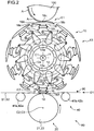
- FIG. 2 is a front view illustrating a schematic configuration of the transfer roller 100 and the transport unit X1.
- the transfer roller 100 transfers the absorbent body A formed in the absorbent body cutting step (5) to a transporting device 10.
- a plurality of absorbent bodies A is attached to the outer surface of the transfer roller 100.
- the absorbent bodies A are placed evenly spaced apart along the circumferential direction of the transfer roller 100.
- the transfer roller 100 transfers the absorbent body A to a pad 18 of the transporting device 10, which will be described later, as the transfer roller 100 and the transporting device 10 rotates. The transfer is performed when the pad 18 is at a receiving position E1.
- the transport unit X1 includes the transporting device 10 that receives the absorbent body A from the transfer roller 100 and conveys the absorbent body A, a receiving unit 80 that joins the absorbent body A, conveyed by the transporting device 10, to the sheets S1 and S2, and applying means 90 that applies an adhesive onto the sheets S1 and S2.
- FIG. 2 A schematic configuration of the transporting device 10 of the transport unit X1 will be described below with reference to Fig. 2 .
- the transporting device 10 includes a pad rotating shaft 11, and a plurality of pads 18 provided, evenly spaced apart, along the circumferential direction of the pad rotating shaft 11.
- the transporting device 10 of the embodiment is provided with ten pads 18.
- the transporting device 10 rotates the pad rotating shaft 11 about a pad rotational axis C1 to rotate the pads 18 about the pad rotating shaft 11.
- the pad 18 rotating about the pad rotating shaft 11 receives the absorbent body A from the transfer roller 100 at the receiving position E1 and transfers the absorbent body A onto the sheets S1 and S2 transported between the transporting device 10 and the receiving unit 80, at the transfer position E2.
- the transporting device 10 turns the pad 18 90 degrees about an axis extending in a radial direction of the pad rotating shaft 11 while the pad 18 rotates from the receiving position E1 to the transfer position E2. That is, at the transfer position E2, the transporting device 10 transfers the absorbent body A, which has been turned around 90 degrees after being received by the pad 18 at the receiving position E1, onto the sheets S1 and S2.
- the pad 18 is turned 90 degrees about an axis extending in a radial direction of the pad rotating shaft 11 while the pad 18 is rotated from the receiving position E1 to the transfer position E2.
- the present invention is not limited to the embodiment.
- the turning angle of the pad may suitably be changed depending on the use mode of the transporting device 10.
- the pad 18 may transfer the absorbent body A with a suitable orientation to the sheets S1 and S2 by being turned a predetermined angle while rotating the receiving position E1 to the transfer position E2.
- Fig. 3 is a side view of the transporting device 10 illustrating a portion that contributes to turning the pad 18.
- the transporting device 10 includes not only the pad rotating shaft 11 and the pads 18 described above but a fixed drum (not shown) provided to surround the pad rotating shaft 11, a speed adjusting cam 12 that is fixed on the distal end of the fixed drum and used to adjust the speed of the pad 18 rotating about the pad rotating shaft 11, a turning cam 19 that is fixed to the outer circumferential surface of the fixed drum and used for turning the pad 18 about the axis extending in a radial direction of the pad rotating shaft 11, and a rotating mechanism that rotates the pad 18 as the pad rotating shaft 11 rotates.
- the rotating mechanism includes an arm 13, a link lever 14, a driving base 15, a turning shaft 16, and a lever 17.
- the pad rotating shaft 11 is rotatable about the pad rotational axis C1.
- the transporting device 10 is disposed such that the pad rotational axis C1 of the pad rotating shaft 11 is parallel to the rotational axis of the transfer roller 100.
- the fixed drum has a cylindrical shape with its central axis on the pad rotational axis C1.
- the pad rotating shaft 11 penetrates the fixed drum and the turning cam 19 and is rotatably supported by the fixed drum and the turning cam 19 via bearings.
- the fixed drum cannot rotate because the fixed drum is fixed to a surface on which the transporting device 10 is set.
- the pad rotating shaft 11 can rotate, relative to the fixed drum, inside the fixed drum.
- the speed adjusting cam 12 is fixed on the distal end of the cylindrical fixed drum so as to plug the opening on the distal end.
- a cam groove 12a is provided in the outer surface of the speed adjusting cam 12. As illustrated in Fig. 2 , the cam groove 12a has an approximately circular shape that is provided eccentric to the pad rotational axis C1.
- the arm 13 is indirectly coupled to the pad rotating shaft 11 via a disk-shaped member (see Fig. 2 ) so as to be rotatable about the pad rotating shaft 11 as the pad rotating shaft 11 rotates.
- the arm 13 is coupled to the disk-shaped member so as to be rotatable about an axis parallel to the pad rotational axis C1.
- ten arms 13 are provided corresponding to the ten pads 18.
- Each arm 13 extends in the direction perpendicular to the pad rotational axis C1.
- a cam follower 13a is provided on the proximal end of each arm 13.
- the cam follower 13a is shifted from the rotational axis of the arm 13.
- the cam follower 13a is inserted in the cam groove 12a of the speed adjusting cam 12 so as to be rotatable about an axis parallel to the pad rotational axis C1.
- the link lever 14 extends from the distal end of the arm 13 in a direction perpendicular to the pad rotational axis C1 and intersecting the direction in which the arm 13 extends.
- Ten link levers 14 are provided corresponding to the ten arms 13.
- the proximal end of each link lever 14 is coupled to the distal end of the arm 13 so as to be rotatable about an axis parallel to the pad rotational axis C1.
- the driving base 15 includes an external wall 15b provided in the outer side of the arm 13 and the link lever 14 with respect to a radial direction of the pad rotational axis C1, and a supported portion 15a protruding from the external wall 15b to the inner side in the radial direction.
- the supported portion 15a is coupled to the distal end of the link lever 14 so as to be rotatable about an axis parallel to the pad rotational axis C1.
- the driving base 15 rotates along a circumference of the pad rotational axis C1.
- the turning cam 19 has a cylindrical shape with its central axis on the pad rotational axis C1.
- the turning cam 19 is fixed to the outer circumferential surface of the fixed drum so as to surround the fixed drum.
- the turning cam 19 is positioned in further inner side than the external wall 15b of the driving base 15 with respect to the radial direction of the pad rotational axis C1.
- a cam groove 19a is provided in the external surface of the turning cam 19. As illustrated in Fig. 3 , the cam groove 19a is formed to encircle the pad rotational axis C1.
- the location in the cam groove 19a with respect to the pad rotational axis C1 changes along the circumferential direction of the pad rotational axis C1.
- the turning shaft 16 extends in a radial direction of the pad rotational axis C1 to penetrate the external wall 15b of the driving base 15.
- the turning shaft 16 is supported by the external wall 15b so as to be rotatable about an axis along a radial direction of the pad rotational axis C1.
- a cam follower 17a is provided via the lever 17 on the inner end, with respect to the radial direction, of the turning shaft 16.
- the lever 17 extends in the direction perpendicular to the turning shaft 16.
- the cam follower 17a is in a position shifted from the rotational axis of the turning shaft 16.
- the cam follower 17a is inserted in the cam groove 19a of the turning cam 19 so as to be rotatable about an axis perpendicular to the pad rotational axis C1.
- the pad 18 is coupled to the outer end, with respect to a radial direction of the pad rotational axis C1, of the turning shaft 16.
- the pad 18 has an approximately rectangular shape extending in one direction in a plan view. As illustrated in Fig. 2 , the pad 18 is positioned such that the longitudinal direction and the rotational direction of the pad 18 are parallel to each other at the receiving position E1. The pad 18 is positioned such that the lateral direction and the rotational direction of the pad 18 are parallel to each other at the transfer position E2. That is, the longitudinal direction of the pad 18 is parallel to the pad rotational axis C1 at the transfer position E2.
- the pad 18 has a holding surface 18A on which the absorbent body A is held.
- the holding surface 18A faces radially outwardly with respect to the pad rotating shaft 11.
- the holding surface 18A is positioned to face the transfer roller 100 at the receiving position E1 to receive the absorbent body A from the transfer roller 100.
- the holding surface 18A is positioned to face the receiving roller 20 at the transfer position E2 to transfer the absorbent body A onto the sheets S1 and S2 conveyed between the holding surface 18A and the receiving roller 20.
- both ends, in the longitudinal direction of the pad 18, of the holding surface 18A are a first end 181 and a second end 182.
- the holding surface 18A has a first sloped surface 18a positioned on the side of the first end 181, a second sloped surface 18b positioned on the side of the second end 182, and a middle surface 18C located between the first sloped surface 18a and the second sloped surface 18b.
- the holding surface 18A has an arc shape protruding to radially outwardly with respect to the pad rotating shaft 11 when viewed along the lateral direction of the pad 18.
- the first sloped surface 18a, the middle surface 18c, and the second sloped surface 18b continues in this order in the longitudinal direction of the pad 18.
- the holding surface 18A has a spherical shape.
- the holding surface 18A also has an arc shape protruding to radially outwardly with respect to the pad rotating shaft 11 when viewed in the longitudinal direction of the pad 18.
- Fig. 5 is a side view illustrating the pad 18 at the transfer position E2 viewed in a direction perpendicular to the pad rotational axis C1 of the pad rotating shaft 11.
- the longitudinal direction of the pad 18 is parallel to the pad rotational axis C1 at the transfer position E2.
- the distance from the pad rotational axis C1 to the first sloped surface 18a of the holding surface 18A decreases toward the first end 181 in the direction of the pad rotational axis C1.
- the distance from the pad rotational axis C1 to the second sloped surface 18b of the holding surface 18A decreases toward the second end 182 in the direction of the pad rotational axis C1.
- the middle surface 18c of the holding surface 18A is farther from the pad rotational axis C1 than the first sloped surface 18a and the second sloped surface 18b.
- the transporting device 10 is configured such that the arm 13, the link lever 14, and the driving base 15 rotate as the pad rotating shaft 11 rotates, and thereby the turning shaft 16 supported by the external wall 15b of the driving base 15 and the pad 18 mounted on the turning shaft 16 turn about the pad rotating shaft 11.
- the arm 13 rotates about an axis parallel to the pad rotational axis C1 by the cam follower 13a inserted in the cam groove 12a in the speed adjusting cam 12 moving along the cam groove 12a.
- the lever 17 coupled to the turning shaft 16 rotates about an axis extending in a radial direction of the pad rotational axis C1 by the cam follower 17a inserted in the cam groove 19a in the turning cam 19 moving along the cam groove 19a.
- the rotational speed of the pad 18 is adjusted and the pad 18 turns about the axis extending in a radial direction of the pad rotational axis C1.
- the pad 18 is turned 90 degrees while being moved from the receiving position E1 to the transfer position E2 so that the longitudinal direction of the pad 18 becomes parallel to the rotational direction at the receiving position E1 and the lateral direction of the pad 18 becomes parallel to the rotational direction at the transfer position E2.
- FIG. 5 is a side view illustrating the pad 18 and an essential portion of the receiving unit 80 at the receiving position E1, viewed in a direction perpendicular to the pad rotational axis C1.
- Fig. 6 is a front view illustrating a schematic configuration of the receiving unit 80.
- the transporting device 10 is illustrated in a simplified manner in Fig. 6 .
- the receiving unit 80 is disposed on the side opposite to the transporting device 10 with respect to the sheets S1 and S2 between the receiving unit 80 and the transporting device 10.
- the sheets are transported in a transporting direction D1 perpendicular to the pad rotational axis C1.
- the receiving position E1 and the transfer position E2 are shifted by 180 degrees about the pad rotational axis C1.
- the receiving unit 80 is disposed to face the transfer roller 100 with the transporting device 10 between the receiving unit 80 and the transfer roller 100.
- the receiving unit 80 includes a receiving roller 20 that joins the absorbent body A to the sheets S1 and S2 at the transfer position E2, auxiliary rollers 30 that help the joining, a guide mechanism 40 that guides the sheets S1 and S2 to be transported, and a driving mechanism 50 that rotates the receiving roller 20 and the auxiliary rollers 30 altogether.
- the receiving roller 20 is disposed so as to sandwich the sheets S1 and S2 between the holding surface 18A of the pad 18 and the receiving roller 20 at the transfer position E2.
- the receiving roller 20 includes a first receiving roller 21 and a second receiving roller 22 disposed in a direction in which the pad rotational axis C1 extends.
- Fig. 7 is a sectional view of the first and second receiving rollers 21 and 22 in a plane including first and second rotational axes C2 and C3, which are rotation centers of the first and second receiving rollers 21 and 22, respectively.
- Fig. 8 is a sectional view of the first receiving roller 21 (second receiving roller 22) in a plane perpendicular to the first rotational axis C2 (second rotational axis C3).
- the first and second receiving rollers 21 and 22 include shaft members 21a and 22a and outer circumferential members 21b and 22b, respectively.
- the outer circumferential members 21b and 22b are made of a relatively soft material, such as polyurethane foam.
- the shaft members 21a and 22a extend along the first and second rotational axes C2 and C3, which are rotation centers of the first and second receiving rollers 21 and 22, respectively.
- the shaft members 21a and 22a are rotatable about the first and second rotational axes C2 and C3, respectively.
- the outer circumferential member 21b (22b) is provided to surround the shaft member 21a (22a).
- the outer circumferential member 21b (22b) rotates about the first rotational axis C2 (second rotational axis C3) as the shaft member 21a (22a) rotates.
- the outer circumferential member 21b (22b) has a cylindrical shape having a thickness gradually decreasing from a proximal end 21A (22A) to a distal end 21B (22B) of the first receiving roller 21 (second receiving roller 22) along the direction in which the first rotational axis C2 (second rotational axis C3) extends.
- the shaft member 21a (22a) is disposed inside the outer circumferential member 21b (22b).
- An outer diameter O2 of the distal end 21B (22B) of the first receiving roller 21 (second receiving roller 22) is smaller than an outer diameter O1 of the proximal end 21A (22A) of the first receiving roller 21 (second receiving roller 22).
- the outer circumferential member 21b (22b) includes a first member 21c (22c) and a second member 21d (22d) that are divided by a plane including the first rotational axis C2 (second rotational axis C3).
- the shape of the first member 21c (22c) and the shape of the second member 21d (22d) are plane symmetric about the plane including the first rotational axis C2 (second rotational axis C3).
- the shaft member 21a (22a) is circumferentially surrounded by the first member 21c (22c) and the second member 21d (22d).
- the first member 21c (22c) is provided with a first through hole 21e (22e) and a first through hole 21f (22f) that penetrate the first member 21c (22c) in a radial direction of the first rotational axis C2 (second rotational axis C3).
- the first through hole 21e (22e) and the first through hole 21f (22f) are arranged in the direction in which the first rotational axis C2 (second rotational axis C3) extends.
- the first member 21c (22c) is detachably attached on the shaft member 21a (22a) by fixing fastening members (not shown) such as bolts or the like inserted in the first through hole 21e (22e) and the first through hole 21f (22f) to the shaft member 21a (22a).
- the first member 21c (22c) is attached on one of sides in a direction perpendicular to the first rotational axis C2 (second rotational axis C3).
- the second member 21d (22d) is provided with a second through hole 21g (22g) and a second through hole 21h (22h) that penetrate the second member 21d (22d) in the radial direction of the first rotational axis C2 (second rotational axis C3).
- the second through hole 21g (22g) and the second through hole 21h (22h) are arranged in the direction in which the first rotational axis C2 (second rotational axis C3) extends.
- the second member 21d (22d) is detachably attached on the shaft member 21a (22a) by fixing fastening members (not shown) such as bolts or the like inserted in the second through hole 21g (22g) and the second through hole 21h (22h) to the shaft member 21a (22a).
- the second member is attached on the other side in the direction perpendicular to the first rotational axis C2 (second rotational axis C3).
- the first member 21c (22c) and the second member 21d (22d) may not be attached on the shaft member 21a (22d) by bolts or the like.
- the first member 21c (22c) and the second member 21d (22d) may be attached on the shaft member 21a (22a) by inserting a portion of the first member 21c (22c) and a portion of the second member 21d (22d) in recesses formed in the outer circumferential surface of the shaft member 21a (22a).
- first member 21c (22c) and the second member 21d (22d) are detachably attached, by a variety of means, on the shaft member 21a (22a) on both sides in a direction intersecting the first rotational axis C2 (second rotational axis C3).
- the first receiving roller 21 is disposed such that the distal end 21B is positioned on the side of the first end 181 of the holding surface 18A of the pad 18 at the transfer position E2 and the first sloped surface 18a faces the outer circumferential surface of the outer circumferential member 21b.
- the first receiving roller 21 is disposed such that the first rotational axis C2 of the first receiving roller 21 inclines along the inclination of the first sloped surface 18a with respect to the pad rotational axis C1 of the transporting device 10.
- the second receiving roller 22 is disposed such that the distal end 22B is positioned on the side of the second end 182 of the holding surface 18A of the pad 18 at the transfer position E2 and the second sloped surface 18b faces the outer circumferential surface of the outer circumferential member 22b.
- the second receiving roller 22 is disposed such that the first rotational axis C3 of the second receiving roller 22 inclines along the inclination of the second sloped surface 18b with respect to the pad rotational axis C1 of the transporting device 10.
- the auxiliary roller 30 includes a shaft member 31 that extends along a third rotational axis C4 which is a rotation center of the auxiliary roller 30 and is rotatable about the third rotational axis C4, and an outer circumferential member 32 that circumferentially surrounds the shaft member 31 and rotates with rotation of the shaft member 31.
- the auxiliary roller 30 is disposed between the first receiving roller 21 and the second receiving roller 22, in a direction of the pad rotational axis C1.
- the auxiliary roller 30 is disposed such that the third rotational axis C4 of the auxiliary roller 30 is parallel to the pad rotational axis C1. Accordingly, the outer circumferential surface of the outer circumferential member 32 of the auxiliary roller 30 faces the middle surface 18c of the pad 18 at the transfer position E2.
- An adhesive is applied by the applying means 90 on the sheets S1 and S2 transported in the transporting direction D1.
- the adhesive is applied in the upstream of the transfer position E2 along the transporting direction D1.
- the front sheet S1 and the absorbent body A on the first sloped surface 18a are sandwiched between the first sloped surface 18a and the outer circumferential member 21b of the first receiving roller 21, and thereby the front sheet S1 and the absorbent body A are joined via the adhesive.
- the rear sheet S2 and the absorbent body A on the second sloped surface 18b are sandwiched between the second sloped surface 18b and the outer circumferential member 22b of the second receiving roller 22, and thereby the rear sheet S2 and the absorbent body A are joined via the adhesive.
- the absorbent body A positioned at the middle surface 18c is sandwiched between the middle surface 18c and the auxiliary roller 30 when the sheets S1 and S2 and the absorbent body A are joined. In this manner, the front sheet S1 and the rear sheet S2 are connected by the absorbent body A and transported to the downstream of the transporting direction D1.
- the adhesive is applied on target portions on the sheets S1 and S2 by the applying means 90.
- the adhesive may be applied on a target portion on the absorbent body A by the applying means 90.
- the driving mechanism 50 includes a driving unit 51, pulleys 52a, 52b, and 52c that are rotated by the driving force of the driving unit 51, first belt rollers 53a and 53b, second belt rollers 54a and 54b, third belt rollers 55a and 55b, and a plurality of belts B running about the belt rollers.
- the first, second, and third belt rollers are respectively provided for the pulleys 52a, 52b, and 52c.
- the pulleys 52a, 52b, and 52c are mutually connected along the pad rotational axis C1 and are each supported by a supporting plate (reference sign not appended) so as to be rotatable about an axis.
- the driving unit 51 is mounted on the distal end of the pulley 52a.
- the pulley 52a is rotated by the driving force of the driving unit 51 and thereby the other pulleys 52b and 52c are rotated.
- the first belt rollers 53a and 53b are provided for the pulley 52a.
- the first belt roller 53a is fixed to the pulley 52a.
- the first belt roller 53b is away from the first belt roller 53a in a direction intersecting the pad rotational axis C1 and is rotatably supported by the supporting plate (reference sign not appended).
- the shaft member 21a of the first receiving roller 21 is fixed to the first belt roller 53b.
- the belt B runs around the first belt roller 53a and the first belt roller 53b.
- the second belt rollers 54a and 54b are provided for the pulley 52b.
- the second belt roller 54a is fixed to the pulley 52b.
- the second belt roller 54b is away from the second belt roller 54a in a direction intersecting the pad rotational axis C1 and is rotatably supported by the supporting plate (reference sign not appended).
- the shaft member 31 of the auxiliary roller 30 is fixed to the second belt roller 54b.
- the belt B runs around the second belt roller 54a and the second belt roller 54b.
- the third belt rollers 55a and 55b are provided for the pulley 52c.
- the third belt roller 55a is fixed to the pulley 52c.
- the third belt roller 55b is away from the third belt roller 55a in a direction intersecting the pad rotational axis C1 and is rotatably supported by the supporting plate (reference sign not appended).
- the shaft member 22a of the second receiving roller 22 is fixed to the third belt roller 55b.
- the belt B runs around the third belt roller 55a and the third belt roller 55b.
- the driving mechanism 50 is configured such that the driving unit 51 simultaneously rotates the pulleys 52a, 52b, and 52c to rotate the first, second, and third belt rollers 53a, 54a, and 55a attached to the pulleys 52a, 52b, and 52c, respectively, and thereby the first, second, and third belt rollers 53b, 54b, and 55b rotate via the belts B. In this manner, the first receiving roller 21, the second receiving roller 22, and the auxiliary roller 30 rotate altogether.
- the guide mechanism 40 includes a pair of first guide rollers 41a and 41b that guide the front sheet S1 to be conveyed in the transporting direction D1, and a pair of second guide rollers 42a and 42b that guide the rear sheet S2 to be conveyed in the transporting direction D1.
- the first guide rollers 41a and 41b are separately disposed from each other in the transporting direction D1 with the first receiving roller 21 between the first guide rollers 41a and 41b.
- the first guide rollers 41a and 41b are rotatably mounted on a support-plate (reference sign not appended) that supports the driving mechanism 50.
- the first guide rollers 41a and 41b are disposed closer to the pad rotational axis C1 of the transporting device 10 than the first receiving roller 21 is, in the direction perpendicular to the transporting direction D1.
- Fig. 5 illustrates the entire portion of the first guide roller 41a closer to the pad rotational axis C1 than the first receiving roller 21. However, actually, the first guide roller 41a partially overlaps the first receiving roller 21 when viewed in the transporting direction D1 as illustrated in Fig. 6 . The same can be said for the first guide roller 41b.
- the second guide rollers 42a and 42b are separately disposed from each other in the transporting direction D1 with the second receiving roller 22 between the second guide rollers 42a and 42b.
- the second guide rollers 42a and 42b are rotatably mounted on a support-plate (reference sign not appended) that supports the driving mechanism 50.
- the second guide rollers 42a and 42b are disposed closer to the pad rotational axis C1 of the transporting device 10 than the second receiving roller 22 is, in the direction perpendicular to the transporting direction D1.
- Fig. 5 illustrates the entire portion of the second guide roller 42a closer to the pad rotational axis C1 than the second receiving roller 22. However, actually, the second guide roller 42a partially overlaps the second receiving roller 22 when viewed in the transporting direction D1 as illustrated in Fig. 6 . The same can be said for the second guide roller 42b.
- Fig. 9 illustrates the transporting device 10 where the pad 18 is about to reach the transfer position E2, and the receiving unit 80 that receives the absorbent body A from the transporting device 10.
- the sheets S1 and S2 extend straight along the transporting direction D1, with the sheet S1 touching the outer circumferential surfaces, facing the transporting device 10, of the first guide rollers 41a and 41b and the sheet S2 touching the outer circumferential surfaces, facing the transporting device 10, of the second guide rollers 42a and 42b.
- the sheets S1 and S2 are away from the first and second receiving rollers 21 and 22, respectively, when the pad 18 is not at the transfer position E2.
- the holding surface 18A of the pad 18 pushes the sheet S1 (S2) to cause the portion of the sheet S1 (S2) between the first guide rollers 41a and 41b (second guide rollers 42a and 42b) in the transporting direction D1 to curve toward the first receiving roller 21 (second receiving roller 22).
- the sheet S1 (S2) thereby contacts the first receiving roller 21 (second receiving roller 22), and thus the sheet S1 (S2) and the absorbent body A are sandwiched between the first receiving roller 21 (second receiving roller 22) and the holding surface 18A of the pad 18.
- the pad 18 of the transporting device 10 receives the absorbent body A from the transfer roller 100 at the receiving position E1 to hold the absorbent body A on the holding surface 18A. Then, the pad 18, with the absorbent body A received on the holding surface 18A at the receiving position E1, rotates about the pad rotational axis C1 to reach the transfer position E2. With this rotation, the pad 18 turns 90 degrees about an axis extending in a radial direction of the pad rotational axis C1. The pad 18 just about to reach the transfer position E2 rotates while pushing the sheets S1 and S2, conveyed straight along the transporting direction D1 by the guide mechanism 40, against the first and second receiving rollers 21 and 22.
- the pad 18 reaches the transfer position E2 to sandwich the sheets S1 and S2 and the absorbent body A between the pad 18 and the first and second receiving rollers 21 and 22.
- the absorbent body A is thereby joined to the sheets S1 and S2 so as to extend from the sheets S1 to S2.
- the pad 18 that has transferred the absorbent body A to the sheets S1 and S2 rotates about the pad rotational axis C1 to reach the receiving position E1. With the rotation, the pad 18 turns 90 degrees about the axis extending in a radial direction of the pad rotational axis C1 to return to the initial position at the receiving position E1.
- the joint assembly formed by joining the absorbent body A to the sheets S1 and S2 at the transfer position E2 is conveyed to the downstream of the transporting direction D1. In the downstream, a predetermined process is performed on the joint assembly.
- the distances from the pad rotating shaft 11 to the first and second sloped surfaces 18a and 18b included in the holding surface 18A decrease toward the first and second ends 181 and 182, which are the ends of the pad 18 in the direction in which the pad rotating shaft 11 extends. Therefore, when the pad 18 is at the transfer position E2, the circumferential speeds on the first and second sloped surfaces 18a and 18b decrease toward the first and second ends 181 and 182, which are the ends of the pad 18 in the direction in which the pad rotating shaft 11 extends.
- the first receiving roller 21 (second receiving roller 22) has a diameter decreasing from the proximal end 21A (22A) toward the distal end 21B (22B) along the first rotational axis C2 (second rotational axis C3), so that the circumferential speed decreases from the proximal end 21A (22A) toward the distal end 21B (22B).
- the first receiving roller 21 sandwiches the sheet S10 and the absorbent body A between the first sloped surface 18a and the first receiving roller with the distal end 21B positioned on the side of the first end 181 of the holding surface 18A
- the second receiving roller 22 sandwiches the sheet S10 and the absorbent body A between the second sloped surface 18b and the second receiving roller with the distal end 22B positioned on the side of the second end 182 of the holding surface 18A.
- the difference in circumferential speed between the first curved surface 18a (second curved surface 18b) and the first receiving roller 21 (second receiving roller 22) is kept small, and thereby forming of crinkles on the absorbent body A or the sheet S10 during joining of the absorbent body A to the sheet S10 is prevented.
- the first rotational axis C2 (second rotational axis C3) is inclined along the inclination of the first sloped surface 18a (second sloped surface 18b) to further prevent a large difference in circumferential speed between the first sloped surface 18a (second sloped surface 18b) and the first receiving roller 21 (second receiving roller 22).
- the front sheet S1 and the absorbent body A are sandwiched between the first sloped surface 18a and the first receiving roller 21 and the rear sheet S2 and the absorbent body A are sandwiched between the second sloped surface 18b and the second receiving roller 22, thereby connecting the front sheet S1 to the rear sheet S2 via the absorbent body A without forming crinkles on the absorbent body A or the sheets S1 and S2.
- the transport unit X1 includes the auxiliary roller 30 for pushing the absorbent body A, positioned at the middle surface 18c, onto the middle surface 18c which is farther apart from the pad rotating shaft 11 than the first sloped surface 18a and the second sloped surface 18b and therefore likely to generate the maximum centrifugal force.
- the outer circumferential member 21b (22b) of the first receiving roller 21 is divided into the first member 21c (22c) and the second member 21d (22d).
- the first and second members 21c and 21d are detachably attached on both sides, with respect to a direction intersecting the first rotational axis C2, of the shaft member 21a, and the first and second members 22c and 22d are detachably attached on both sides, with respect to a direction intersecting the second rotational axis C3, of the shaft member 22a.
- the outer circumferential members 21b and 22b can easily be replaced when the outer circumferential members 21b and 22b wear by making contact with the sheets S1 and S2.
- the guide mechanism 40 guides the sheets S1 and S2 to be transported so that the sheets S1 and S2 are not in contact with the first and second receiving rollers 21 and 22 while the pad 18 is at a position other than the transfer position E2. This prevents wear of the outer circumferential members 21b and 22b of the first and second receiving rollers 21 and 22 caused by the first and second receiving rollers 21 and 22 making contact with the sheets S1 and S2 for a long period of time.
- the sheet S10 is composed of two independent sheets, which are the front sheet S1 and the rear sheet S2.
- the sheet S10 may be composed of a single sheet.
- the first and second sloped surfaces 18a and 18b each has a curved shape.
- the shapes of the first and second sloped surfaces 18a and 18b are not limited to a curved shape.
- the first and second sloped surfaces 18a and 18b may have any shapes such that the distances from the pad rotating shaft 11 to the first and second sloped surfaces 18a and 18b decrease toward the first and second ends 181 and 182 so that the absorbent body A is smoothly received from the transfer roller 100 at the receiving position E1.
- the first and second sloped surfaces 18a and 18b each may have a flat shape.
- the middle surface 18c has a curved shape.
- the shape of the middle surface is not limited to a curved shape.
- the middle surface 18c may have a flat shape extending in the longitudinal direction of the pad 18 between the inner edges of the first and second sloped surfaces 18a and 18b.
- the guide mechanism 40 includes the first guide rollers 41a and 41b disposed on both sides of the first receiving roller 21 in the transporting direction D, and the second guide rollers 42a and 42b disposed on both sides of the second receiving roller 22 in the transporting direction D.
- the guide mechanism 40 is not limited to the above.
- the guide mechanism 40 may have any configuration that can guide the sheet S1 (S2) to be conveyed such that the sheet S1 (S2) is away from the first receiving roller 21 (second receiving roller 22) while the pad 18 is at a position other than the transfer position E2.
- the number and dispositions of the guide rollers included in the guide mechanism 40 are not particularly limited.
- the guide mechanism 40 may not include a guide roller but may include an unrotatable guiding member.
- the outer circumferential member 21b (22b) of the first receiving roller 21 (22) is divided into the first member 21c (22c) and the second member 21d (22d).
- the present invention is not limited to the embodiment.
- only the outer circumferential member 21b of the first receiving roller 21 may be divided into the first member 21c and the second member 21d while the entire outer circumferential member 21b of the second receiving roller 22 forms a single part.
- a transport unit is a transport unit that conveys a first transportation object onto a second transportation object and joins the first transportation object to the second transportation object.
- the transport unit includes: a transporting device including a pad rotating shaft, and a pad having a holding surface that faces radially outwardly with respect to the pad rotating shaft and is capable of holding the first transportation object, the transporting device being configured to rotate the pad about the pad rotating shaft and to turn the pad about an axis extending in a radial direction of the pad rotating shaft while the pad is rotated from a receiving position where the pad receives the first transportation object to a transfer position where the pad transfers the first transportation object onto the second transportation object; and a receiving roller that, when the pad rotates and comes to the transfer position, rotates while sandwiching the first transportation object and the second transportation object between the holding surface of the pad and the receiving roller to join the first transportation object to the second transportation object and guide the second transportation object to a predetermined direction.
- the holding surface includes a first sloped surface and a second sloped surface, the first sloped surface and the second sloped surface being such that, when the pad is at the transfer position, a distance from the pad rotating shaft to the first sloped surface decreases toward a first end along the pad rotating shaft, while a distance from the pad rotating shaft to the second sloped surface decreases toward a second end along the pad rotating shaft.
- the receiving roller includes a first receiving roller and a second receiving roller.
- the first receiving roller is disposed such that an outer diameter of the first receiving roller decreases from a proximal end to a distal end along a first rotational axis which is a rotation center of the first receiving roller, and the distal end of the first receiving roller is positioned on the side of the first end of the holding surface to sandwich the first transportation object and the second transportation object between the first sloped surface and the first receiving roller when the pad is at the transfer position
- the second receiving roller is disposed such that an outer diameter of the second receiving roller decreases from a proximal end to a distal end along a second rotational axis which is a rotation center of the second receiving roller, and the distal end of the second receiving roller is positioned on the side of the second end of the holding surface to sandwich the first transportation object and the second transportation object between the second sloped surface and the second receiving roller when the pad is at the transfer position.
- the distance from the pad rotating shaft to the first sloped surface (second sloped surface) included in the holding surface decreases toward the first end (second end), which is an end of the pad in the direction in which the pad rotating shaft extends. Therefore, when the pad is at the transfer position, the circumferential speed of the first sloped surface (second sloped surface) decreases toward the first end (second end), which is an end of the pad in the direction in which the pad rotating shaft extends.
- the first receiving roller (second receiving roller) has a diameter decreasing from the proximal end toward the distal end along the first rotational axis (second rotational axis), which is the rotation center of the first receiving roller (second receiving roller), so that the circumferential speed of the first receiving roller (second receiving roller) decreases from the proximal end toward the distal end.
- the first receiving roller sandwiches the first transportation object and the second transportation object between the first sloped surface and the first receiving roller with the distal end of the first receiving roller positioned on the side of the first end of the holding surface
- the second receiving roller sandwiches the first transportation object and the second transportation object between the second sloped surface and the second receiving roller with the distal end of the second receiving roller positioned on the side of the second end of the holding surface.
- the first and second sloped surfaces of the pad of the transport unit may not necessarily have a flat shape but may have a curved shape.
- first receiving roller is disposed to face the first sloped surface with the first rotational axis inclined along an inclination of the first sloped surface
- second receiving roller is disposed to face the second sloped surface with the second rotational axis inclined along an inclination of the second sloped surface
- the first rotational axis (second rotational axis) is inclined along the inclination of the first sloped surface (second sloped surface), so that the difference in circumferential speed between the first sloped surface (second sloped surface) and the first receiving roller (second receiving roller) is kept small.
- the second transportation object includes a first transportation element and a second transportation element
- the transporting device conveys the first transportation object so that the first transportation object extends from the first transportation element to the second transportation element when the pad is at the transfer position
- the first receiving roller is disposed so as to sandwich the first transportation object and the first transportation element between the first sloped surface and the first receiving roller when the pad is at the transfer position
- the second receiving roller is disposed so as to sandwich the first transportation object and the second transportation element between the second sloped surface and the second receiving roller when the pad is at the transfer position.
- the first transportation object and the first transportation element are sandwiched between the first sloped surface and the first receiving roller while the first transportation object and the second transportation element are sandwiched between the second sloped surface and the second receiving roller, thereby connecting the first transportation element to the second transportation element by the first transportation object without forming crinkles on the first transportation object or the second transportation object.
- the holding surface includes a middle surface provided between the first sloped surface and the second sloped surface in a direction along the pad rotating shaft when the pad is at the transfer position, a distance from the pad rotating shaft to the middle surface being longer than a distance from the pad rotating shaft to the first sloped surface and a distance from the pad rotating shaft to the second sloped surface
- the transport unit further includes an auxiliary roller that is positioned between the first receiving roller and the second receiving roller in a direction along the pad rotating shaft and that rotates while sandwiching the first transportation object between the middle surface and the auxiliary roller when the pad rotates and comes to the transfer position.
- the transport unit includes the auxiliary roller for pushing a portion of the first transportation object, positioned at the middle surface, onto the middle surface which is farther apart from the rotating shaft than the first sloped surface and the second sloped surface and therefore likely to generate the maximum centrifugal force. This prevents the first transportation object from being joined to the first transportation element and the second transportation element with a gap between the portion of the first transportation object and the middle surface, and thereby forming of crinkles on the first transportation object or on the second transportation object can further be prevented.
- the first receiving roller includes a shaft member rotatable about the first rotational axis, and an outer circumferential member that surrounds a circumference of the shaft member and sandwiches the first transportation object and the second transportation object between the holding surface and the first receiving roller, the outer circumferential member includes a first member and a second member, the outer circumferential member is divided into the first member and the second member in a direction perpendicular to the first rotational axis, and the first member and the second member are detachably attached on both sides of the shaft member in a direction intersecting the first rotational axis.
- the outer circumferential member of the first receiving roller is divided into the first member and the second member which are detachably attached on both sides of the shaft member. This allows easy replacement of the first and second members when the first and second members wear by making contact with the second transportation object, for example.
- the transport unit further includes a guide mechanism that is provided on opposite side of the transporting device with respect to the second transportation object and is configured to guide the second transportation object such that the second transportation object is away from the receiving roller when the pad is at a position other than the transfer position, and the second transportation object pushed by the holding surface of the pad at the transfer position makes contact with the receiving roller.
- a guide mechanism that is provided on opposite side of the transporting device with respect to the second transportation object and is configured to guide the second transportation object such that the second transportation object is away from the receiving roller when the pad is at a position other than the transfer position, and the second transportation object pushed by the holding surface of the pad at the transfer position makes contact with the receiving roller.
- the guide mechanism guides the second transportation object to be transported so that the first transportation object is not in contact with the second transportation object while the pad is at a position other than the transfer position. This prevents wear of the receiving roller caused by the second transportation object making contact with the receiving roller for a long period of time.
- a method for manufacturing a disposable wearing article using a transport unit according to an aspect of the present invention uses the transport unit according to any one of claims 1 to 5 to manufacture a disposable wearing article including a waist part that is to be positioned around a waist of a wearer and a crotch part that is to be positioned at a crotch of the wearer.
- the method includes: a sheet transporting step of conveying a waist sheet along a longitudinal direction of the waist sheet by using the transport unit, the waist sheet corresponding to the second transportation object and being to form the waist part; a crotch section element joining step of transporting a crotch section element that corresponds to the first transportation object and is provided to form a portion corresponding to the crotch part onto the waist sheet and joining the crotch section element to the waist sheet to form a joint assembly; a folding step of folding the joint assembly in a width direction perpendicular to the longitudinal direction; a side sealing step of joining overlapping portions of the waist sheet on both sides with respect to the crotch section element in the longitudinal direction to form side seals; and a cutting step of cutting the waist sheet so that the side seals remain on both the sides with respect to the crotch section element in the longitudinal direction to form a disposable wearing article.
- the crotch section element is conveyed onto the waist sheet and the crotch section element is joined to the waist sheet using the transport unit according to the present invention, so that forming of crinkles on the crotch part or the waist part of the disposable wearing article is prevented.
Landscapes
- Health & Medical Sciences (AREA)
- Engineering & Computer Science (AREA)
- Vascular Medicine (AREA)
- Epidemiology (AREA)
- Biomedical Technology (AREA)
- Heart & Thoracic Surgery (AREA)
- Life Sciences & Earth Sciences (AREA)
- Animal Behavior & Ethology (AREA)
- General Health & Medical Sciences (AREA)
- Public Health (AREA)
- Veterinary Medicine (AREA)
- Manufacturing & Machinery (AREA)
- Mechanical Engineering (AREA)
- Absorbent Articles And Supports Therefor (AREA)
- Collation Of Sheets And Webs (AREA)
Abstract
Description
- The present invention relates to a transport unit that conveys a first transportation object onto a second transportation object and joins the first transportation object to the second transportation object.
- A conventional transport unit has been known that conveys a first transportation object onto a second transportation object and joins the first transportation object to the second transportation object.
Patent Literature 1 discloses such a transport unit that includes a rotatable rotating drum having a suction part that holds an absorbent body by suction, which is the first transportation object, and a cylindrical roller mechanism that rotates while sandwiching the absorbent body and a web, which is the second transportation object, between the rotating drum and the cylindrical roller mechanism to join the absorbent body to the web. The rotating drum disclosed inPatent Literature 1 makes the suction part receive the absorbent body at a receiving point and then rotate to a transfer point to transfer the absorbent body onto the web at the transfer point. The suction part turns 90 degrees about a radial direction of the rotating drum while being moved from the receiving point to the transfer point, and the suction part transfers the absorbent body onto the web in a state where the absorbent body is turned 90 degrees from the orientation of the absorbent body on the suction part at the receiving point. - The outer surface of the suction part disclosed in
Patent Literature 1 has, for example, sloped surfaces to receive the absorbent body smoothly at the receiving point. When the suction part is at the receiving point, the sloped surfaces are sloped radially inward toward both ends in the rotating direction of the rotating drum. As the suction part turns 90 degrees while being moved from the receiving point to the transfer point, the sloped surfaces of the outer surface of the suction part at the transfer point are sloped radially inward toward both ends in the rotational axis direction of the rotating drum. - The rotating drum disclosed in
Patent Literature 1 is configured such that the sloped surfaces of the outer surface of the suction part at the transfer point are sloped radially inward toward both the ends in the rotational axis direction, which generates differences in circumferential speed on the sloped surfaces. The absorbent body disposed on the sloped surfaces is sandwiched between the sloped surfaces of the outer surface of the suction part and the outer surface of the cylindrical roller mechanism to be joined to the web. The circumferential speed on the sloped surfaces of the outer surface of the suction part varies in the rotational axis direction of the rotating drum, whereas the circumferential speed on the outer surface of the roller mechanism has no variation in the rotational axis direction of the roller mechanism. Thus, the absorbent body, which is the first transportation object, and the web, which is the second transportation object, might be joined with crinkles formed on the absorbent body or the web. - Patent Literature 1: Japanese Unexamined Patent Publication No.
2010-115427 Fig. 7 ) - An object of the present invention is to provide a transport unit that solves the aforementioned problem, and a method for manufacturing a disposable wearing article using the transport unit.
- A transport unit according to an aspect of the present invention is a transport unit that conveys a first transportation object onto a second transportation object and joins the first transportation object to the second transportation object. The transport unit includes: a transporting device including a pad rotating shaft, and a pad having a holding surface that faces radially outwardly with respect to the pad rotating shaft and is capable of holding the first transportation object, the transporting device being configured to rotate the pad about the pad rotating shaft and to turn the pad about an axis extending in a radial direction of the pad rotating shaft while the pad is rotated from a receiving position where the pad receives the first transportation object to a transfer position where the pad transfers the first transportation object onto the second transportation object; and a receiving roller that, when the pad rotates and comes to the transfer position, rotates while sandwiching the first transportation object and the second transportation object between the holding surface of the pad and the receiving roller to join the first transportation object to the second transportation object and guide the second transportation object to a predetermined direction. The holding surface includes a first sloped surface and a second sloped surface, the first sloped surface and the second sloped surface being such that, when the pad is at the transfer position, a distance from the pad rotating shaft to the first sloped surface decreases toward a first end along the pad rotating shaft, while a distance from the pad rotating shaft to the second sloped surface decreases toward a second end along the pad rotating shaft. The receiving roller includes a first receiving roller and a second receiving roller. The first receiving roller is disposed such that an outer diameter of the first receiving roller decreases from a proximal end to a distal end along a first rotational axis which is a rotation center of the first receiving roller, and the distal end of the first receiving roller is positioned on the side of the first end of the holding surface to sandwich the first transportation object and the second transportation object between the first sloped surface and the first receiving roller when the pad is at the transfer position, and the second receiving roller is disposed such that an outer diameter of the second receiving roller decreases from a proximal end to a distal end along a second rotational axis which is a rotation center of the second receiving roller, and the distal end of the second receiving roller is positioned on the side of the second end of the holding surface to sandwich the first transportation object and the second transportation object between the second sloped surface and the second receiving roller when the pad is at the transfer position.
- The transport unit is capable of preventing forming of crinkles on the first transportation object or the second transportation object when joining the first transportation object to the second transportation object.
-
- [
Fig. 1] Fig. 1 is a schematic process diagram illustrating a method for manufacturing a disposable diaper according to an embodiment. - [
Fig. 2] Fig. 2 is a front view illustrating a schematic configuration of a transport unit and a transfer roller according to the embodiment, where two of a plurality of pads are respectively at a receiving position and a transfer position. - [
Fig. 3] Fig. 3 is a side view illustrating a schematic configuration of a transporting device according to the embodiment. - [
Fig. 4] Fig. 4 is a perspective view illustrating a schematic configuration of a pad of the transporting device according to the embodiment. - [
Fig. 5] Fig. 5 is a side view illustrating a schematic configuration of a pad and a receiving unit, where the pad is at the transfer position. - [
Fig. 6] Fig. 6 is a front view illustrating a schematic configuration of a receiving unit according to the embodiment. - [
Fig. 7] Fig. 7 is a sectional view, taken along a plane including an axis, illustrating a schematic configuration of a first receiving roller among receiving rollers according to the embodiment. - [
Fig. 8] Fig. 8 is a sectional view, taken along a plane perpendicular to an axis, illustrating a schematic configuration of a first receiving roller among receiving rollers according to the embodiment. - [
Fig. 9] Fig. 9 is a front view illustrating a schematic configuration of a transport unit and a transfer roller according to the embodiment, where none of the pads is at the receiving position nor at the transfer position. - An embodiment of the present invention will now be described with reference to the drawings. For convenience of explanation,
Fig. 1 referred below illustrates, in a simplified manner, only major steps among the manufacturing steps in a method for manufacturing a disposable wearingarticle 1 according to the embodiment. For convenience of explanation,Figs. 2 to 9 referred below illustrate, in a simplified manner, only major components among the components of a transport unit X1 according to the embodiment. A transport unit according to the present invention and a method for manufacturing a disposable wearing article using the transport unit may include a component or a step not illustrated in the drawings referred in the description. -
Fig. 1 is a process diagram illustrating a method for manufacturing adisposable diaper 1, which is an example of the disposable wearing article according to the present invention. - The
disposable diaper 1 includes a front part (waist part) 2 that is to be positioned in front of the belly of a wearer, a back part (waist part) 3 that is to be positioned at the buttock of the wearer, and acrotch part 4 that is to be positioned at the crotch of the wearer. - An end of the
front part 2 and an end of theback part 3 are joined together by a side seal SS. Thefront part 2 and theback part 3 are expandable. Specifically, thefront part 2 and theback part 3 may be formed of an elastic material (elastic non-woven cloth) or by attaching a stretched elastic member between a pair of sheets made of non-woven cloth. The elastic member may be formed of polyurethane, natural rubber, or thermoplastic resin. The elastic member may have a string shape or a ribbon shape. - The
crotch part 4 is joined to thefront part 2 and theback part 3 so as to bridge between thefront part 2 and theback part 3. - The
crotch part 4 of the embodiment is formed of an absorbent body A capable of absorbing body fluid such as urine of a wearer. Specifically, the absorbent body A includes a liquid permeable top sheet S4 provided to face the skin of a wearer, a cover sheet S3 provided to face the side opposite the skin of a wearer, and an absorbent core A1 provided between the sheets S3 and S4. The body fluid permeated through the top sheet S4 is absorbed by the absorbent core A1. The top sheet S4 may be formed of non-woven cloth or a mesh sheet that allows liquid to permeate therethrough. The cover sheet S3 may be formed of a polyethylene film having air permeability, a non-woven cloth having water repellency and air permeability, or a layered sheet composed of such films or non-woven cloths. The absorbent core A1 may be formed by layering fibrillated fluffs made by crushing a roll pulp. High water-absorptive polymer may be mixed in the fluff. - The embodiment includes the
crotch part 4 formed of, but not limited to, the absorbent body A. For example, thecrotch part 4 not including the absorbent core A1 may be used. - The
disposable diaper 1 described above includes thefront part 2 and theback part 3 provided independently. The disposable diaper may not necessarily have such a configuration. For example, a sheet may have a part serving as thefront part 2 and a part serving as theback part 3 and be provided with two leg holes, so that the portion of the sheet between the leg holes serve as thecrotch part 4. In this case, the absorbent body A can be joined to the portion of the sheet between the leg holes. - A method for manufacturing the
disposable diaper 1 will now be described with reference toFig. 1 . - The method for manufacturing the
disposable diaper 1 includes a waist sheet transporting step (1), a crotch sheet transporting step (2), a core joining step (3), a sheet joining step (4), an absorbent body cutting step (5), an absorbent body joining step (6), a folding step (7), a side sealing step (8), and a cutting step (9). - In the waist sheet transporting step (1), a sheet S10, which is an example of a second transportation object according to the embodiment, is conveyed along the longitudinal direction of the sheet S10. The sheet S10 includes a front sheet (waist sheet) S1, which is an example of a first transportation element according to the present invention, and a rear sheet (waist sheet) S2, which is an example of a second transportation element according to the present invention. The front sheet S1 forms the
front part 2 of thedisposable diaper 1. The rear sheet S2 forms theback part 3 of thedisposable diaper 1. The front sheet S1 and the rear sheet S2 are conveyed parallel with a gap therebetween. The waist sheet transporting step (1) is performed with the front sheet S1 and the rear sheet S2 given a predetermined tension until completion of the cutting step (9), which will be described later. - In the crotch sheet transporting step (2), the cover sheet S3 is conveyed along the longitudinal direction of the cover sheet S3. The direction of transporting the cover sheet S3 is parallel to the direction of transporting the front sheet S1 and the rear sheet S2. The crotch sheet transporting step (2) is performed with the cover sheet S3 given a predetermined tension until completion of the absorbent body cutting step (5), which will be described later.
- In the core joining step (3), the cover sheet S3 is joined to the absorbent core A1 disposed on the cover sheet S3.
- In the sheet joining step (4), the top sheet S4 is disposed on the cover sheet S3 with the absorbent core A1 between the top sheet S4 and the cover sheet S3, and the top sheet S4 is joined to the cover sheet S3 to form a continuous body of the absorbent body A (reference sign omitted).
- In the absorbent body cutting step (5), the cover sheet S3 and the top sheet S4 are cut at a position between the absorbent cores A1 to cut out an absorbent body A from the continuous body. The absorbent body A is an example of the first transportation object according to the present invention.
- In the absorbent body joining step (6), the absorbent body (crotch section element) A is turned 90 degrees and conveyed to a position where the absorbent body A extends from the front sheet S1 to the rear sheet S2, and an end of the absorbent body A is joined to the front sheet S1 while the other end of the absorbent body A is joined to the rear sheet S2 to form a joint assembly (reference sign omitted). In this step, for example, an adhesive is provided at a predetermined location on the front sheet S1 and the rear sheet S2 to join both the sheets S1 and S2 to the absorbent body A via the adhesive.
- In the folding step (7), the joint assembly is folded in the width direction perpendicular to the longitudinal direction of the sheets S1 and S2.
- In the side sealing step (8), the overlapping portions of the sheets S1 and S2 are joined on both sides with respect to the absorbent body A in the longitudinal direction of the sheets S1 and S2 to form side seals SS.
- In the cutting step (9), the sheets S1 and S2 are cut so that the side seals SS remain on both the sides with respect to the absorbent body A in the longitudinal direction of the sheets S1 and S2 to form a
disposable diaper 1. - In the manufacturing method described above, the absorbent body A is disposed from the front sheet S1 to the rear sheet S2, which are conveyed parallel, and then the absorbent body A is joined to the sheets S1 and S2. The manufacturing method according to the present invention is not limited to the steps described above.
- For example, in the waist sheet transporting step (1), a waist sheet having parts serving as the
front part 2 and theback part 3 may be transported. In this case, a plurality of leg holes is formed in the waist sheet, and thus a portion serving as thecrotch part 4 is formed between the leg holes in the waist sheet. In the absorbent body joining step (6), the absorbent body A is joined to the portion between the leg holes in the waist sheet. - A
transfer roller 100 and a transport unit X1 used for performing the absorbent body joining step (6) will now be described below with reference toFig. 2. Fig. 2 is a front view illustrating a schematic configuration of thetransfer roller 100 and the transport unit X1. - The
transfer roller 100 transfers the absorbent body A formed in the absorbent body cutting step (5) to a transportingdevice 10. A plurality of absorbent bodies A is attached to the outer surface of thetransfer roller 100. The absorbent bodies A are placed evenly spaced apart along the circumferential direction of thetransfer roller 100. Thetransfer roller 100 transfers the absorbent body A to apad 18 of the transportingdevice 10, which will be described later, as thetransfer roller 100 and the transportingdevice 10 rotates. The transfer is performed when thepad 18 is at a receiving position E1. - The transport unit X1 includes the transporting
device 10 that receives the absorbent body A from thetransfer roller 100 and conveys the absorbent body A, a receivingunit 80 that joins the absorbent body A, conveyed by the transportingdevice 10, to the sheets S1 and S2, and applyingmeans 90 that applies an adhesive onto the sheets S1 and S2. - A schematic configuration of the transporting
device 10 of the transport unit X1 will be described below with reference toFig. 2 . - The transporting
device 10 includes apad rotating shaft 11, and a plurality ofpads 18 provided, evenly spaced apart, along the circumferential direction of thepad rotating shaft 11. The transportingdevice 10 of the embodiment is provided with tenpads 18. - The transporting
device 10 rotates thepad rotating shaft 11 about a pad rotational axis C1 to rotate thepads 18 about thepad rotating shaft 11. Thepad 18 rotating about thepad rotating shaft 11 receives the absorbent body A from thetransfer roller 100 at the receiving position E1 and transfers the absorbent body A onto the sheets S1 and S2 transported between the transportingdevice 10 and the receivingunit 80, at the transfer position E2. - The transporting
device 10 turns thepad 18 90 degrees about an axis extending in a radial direction of thepad rotating shaft 11 while thepad 18 rotates from the receiving position E1 to the transfer position E2. That is, at the transfer position E2, the transportingdevice 10 transfers the absorbent body A, which has been turned around 90 degrees after being received by thepad 18 at the receiving position E1, onto the sheets S1 and S2. - In the embodiment, the
pad 18 is turned 90 degrees about an axis extending in a radial direction of thepad rotating shaft 11 while thepad 18 is rotated from the receiving position E1 to the transfer position E2. The present invention is not limited to the embodiment. The turning angle of the pad may suitably be changed depending on the use mode of the transportingdevice 10. Thepad 18 may transfer the absorbent body A with a suitable orientation to the sheets S1 and S2 by being turned a predetermined angle while rotating the receiving position E1 to the transfer position E2. - A specific configuration of the transporting
device 10 will now be described with reference toFig. 3 as well asFig. 2 .Fig. 3 is a side view of the transportingdevice 10 illustrating a portion that contributes to turning thepad 18. - The transporting
device 10 includes not only thepad rotating shaft 11 and thepads 18 described above but a fixed drum (not shown) provided to surround thepad rotating shaft 11, aspeed adjusting cam 12 that is fixed on the distal end of the fixed drum and used to adjust the speed of thepad 18 rotating about thepad rotating shaft 11, a turningcam 19 that is fixed to the outer circumferential surface of the fixed drum and used for turning thepad 18 about the axis extending in a radial direction of thepad rotating shaft 11, and a rotating mechanism that rotates thepad 18 as thepad rotating shaft 11 rotates. The rotating mechanism includes anarm 13, alink lever 14, a drivingbase 15, a turningshaft 16, and alever 17. With thearm 13 coupled to thespeed adjusting cam 12 and thelever 17 coupled to the turningcam 19, the speed of thepad 18 in the circumferential direction of thepad rotating shaft 11 is adjusted and thepad 18 is turned about an axis extending in a radial direction of thepad rotating shaft 11. - The
pad rotating shaft 11 is rotatable about the pad rotational axis C1. The transportingdevice 10 is disposed such that the pad rotational axis C1 of thepad rotating shaft 11 is parallel to the rotational axis of thetransfer roller 100. - The fixed drum has a cylindrical shape with its central axis on the pad rotational axis C1. The
pad rotating shaft 11 penetrates the fixed drum and the turningcam 19 and is rotatably supported by the fixed drum and the turningcam 19 via bearings. The fixed drum cannot rotate because the fixed drum is fixed to a surface on which the transportingdevice 10 is set. Thus, thepad rotating shaft 11 can rotate, relative to the fixed drum, inside the fixed drum. - The
speed adjusting cam 12 is fixed on the distal end of the cylindrical fixed drum so as to plug the opening on the distal end. Acam groove 12a is provided in the outer surface of thespeed adjusting cam 12. As illustrated inFig. 2 , thecam groove 12a has an approximately circular shape that is provided eccentric to the pad rotational axis C1. - The
arm 13 is indirectly coupled to thepad rotating shaft 11 via a disk-shaped member (seeFig. 2 ) so as to be rotatable about thepad rotating shaft 11 as thepad rotating shaft 11 rotates. Thearm 13 is coupled to the disk-shaped member so as to be rotatable about an axis parallel to the pad rotational axis C1. In the embodiment, tenarms 13 are provided corresponding to the tenpads 18. Eacharm 13 extends in the direction perpendicular to the pad rotational axis C1. Acam follower 13a is provided on the proximal end of eacharm 13. Thecam follower 13a is shifted from the rotational axis of thearm 13. Thecam follower 13a is inserted in thecam groove 12a of thespeed adjusting cam 12 so as to be rotatable about an axis parallel to the pad rotational axis C1. - The
link lever 14 extends from the distal end of thearm 13 in a direction perpendicular to the pad rotational axis C1 and intersecting the direction in which thearm 13 extends. Ten link levers 14 are provided corresponding to the tenarms 13. The proximal end of eachlink lever 14 is coupled to the distal end of thearm 13 so as to be rotatable about an axis parallel to the pad rotational axis C1. - The driving
base 15 includes anexternal wall 15b provided in the outer side of thearm 13 and thelink lever 14 with respect to a radial direction of the pad rotational axis C1, and a supportedportion 15a protruding from theexternal wall 15b to the inner side in the radial direction. The supportedportion 15a is coupled to the distal end of thelink lever 14 so as to be rotatable about an axis parallel to the pad rotational axis C1. The drivingbase 15 rotates along a circumference of the pad rotational axis C1. - The turning
cam 19 has a cylindrical shape with its central axis on the pad rotational axis C1. The turningcam 19 is fixed to the outer circumferential surface of the fixed drum so as to surround the fixed drum. The turningcam 19 is positioned in further inner side than theexternal wall 15b of the drivingbase 15 with respect to the radial direction of the pad rotational axis C1. Acam groove 19a is provided in the external surface of the turningcam 19. As illustrated inFig. 3 , thecam groove 19a is formed to encircle the pad rotational axis C1. The location in thecam groove 19a with respect to the pad rotational axis C1 changes along the circumferential direction of the pad rotational axis C1. - The turning
shaft 16 extends in a radial direction of the pad rotational axis C1 to penetrate theexternal wall 15b of the drivingbase 15. The turningshaft 16 is supported by theexternal wall 15b so as to be rotatable about an axis along a radial direction of the pad rotational axis C1. Acam follower 17a is provided via thelever 17 on the inner end, with respect to the radial direction, of the turningshaft 16. Thelever 17 extends in the direction perpendicular to the turningshaft 16. Thecam follower 17a is in a position shifted from the rotational axis of the turningshaft 16. Thecam follower 17a is inserted in thecam groove 19a of the turningcam 19 so as to be rotatable about an axis perpendicular to the pad rotational axis C1. - The
pad 18 is coupled to the outer end, with respect to a radial direction of the pad rotational axis C1, of the turningshaft 16. In the embodiment, thepad 18 has an approximately rectangular shape extending in one direction in a plan view. As illustrated inFig. 2 , thepad 18 is positioned such that the longitudinal direction and the rotational direction of thepad 18 are parallel to each other at the receiving position E1. Thepad 18 is positioned such that the lateral direction and the rotational direction of thepad 18 are parallel to each other at the transfer position E2. That is, the longitudinal direction of thepad 18 is parallel to the pad rotational axis C1 at the transfer position E2. - The
pad 18 has a holdingsurface 18A on which the absorbent body A is held. The holdingsurface 18A faces radially outwardly with respect to thepad rotating shaft 11. The holdingsurface 18A is positioned to face thetransfer roller 100 at the receiving position E1 to receive the absorbent body A from thetransfer roller 100. The holdingsurface 18A is positioned to face the receivingroller 20 at the transfer position E2 to transfer the absorbent body A onto the sheets S1 and S2 conveyed between the holdingsurface 18A and the receivingroller 20. - As illustrated in
Fig. 4 , both ends, in the longitudinal direction of thepad 18, of the holdingsurface 18A are afirst end 181 and asecond end 182. With respect to the longitudinal direction of the pad, the holdingsurface 18A has a firstsloped surface 18a positioned on the side of thefirst end 181, a secondsloped surface 18b positioned on the side of thesecond end 182, and a middle surface 18C located between the firstsloped surface 18a and the secondsloped surface 18b. In the embodiment, the holdingsurface 18A has an arc shape protruding to radially outwardly with respect to thepad rotating shaft 11 when viewed along the lateral direction of thepad 18. The firstsloped surface 18a, themiddle surface 18c, and the secondsloped surface 18b continues in this order in the longitudinal direction of thepad 18. - In the embodiment, the holding
surface 18A has a spherical shape. Thus, the holdingsurface 18A also has an arc shape protruding to radially outwardly with respect to thepad rotating shaft 11 when viewed in the longitudinal direction of thepad 18. -
Fig. 5 is a side view illustrating thepad 18 at the transfer position E2 viewed in a direction perpendicular to the pad rotational axis C1 of thepad rotating shaft 11. The longitudinal direction of thepad 18 is parallel to the pad rotational axis C1 at the transfer position E2. As illustrated inFig. 5 , at the transfer position E2, the distance from the pad rotational axis C1 to the firstsloped surface 18a of the holdingsurface 18A decreases toward thefirst end 181 in the direction of the pad rotational axis C1. At the transfer position E2, the distance from the pad rotational axis C1 to the secondsloped surface 18b of the holdingsurface 18A decreases toward thesecond end 182 in the direction of the pad rotational axis C1. At the transfer position E2, themiddle surface 18c of the holdingsurface 18A is farther from the pad rotational axis C1 than the firstsloped surface 18a and the secondsloped surface 18b. - The transporting
device 10 is configured such that thearm 13, thelink lever 14, and the drivingbase 15 rotate as thepad rotating shaft 11 rotates, and thereby the turningshaft 16 supported by theexternal wall 15b of the drivingbase 15 and thepad 18 mounted on the turningshaft 16 turn about thepad rotating shaft 11. Thearm 13 rotates about an axis parallel to the pad rotational axis C1 by thecam follower 13a inserted in thecam groove 12a in thespeed adjusting cam 12 moving along thecam groove 12a. Thelever 17 coupled to the turningshaft 16 rotates about an axis extending in a radial direction of the pad rotational axis C1 by thecam follower 17a inserted in thecam groove 19a in the turningcam 19 moving along thecam groove 19a. While thepad 18 rotates about the pad rotational axis C1, the rotational speed of thepad 18 is adjusted and thepad 18 turns about the axis extending in a radial direction of the pad rotational axis C1. Thepad 18 is turned 90 degrees while being moved from the receiving position E1 to the transfer position E2 so that the longitudinal direction of thepad 18 becomes parallel to the rotational direction at the receiving position E1 and the lateral direction of thepad 18 becomes parallel to the rotational direction at the transfer position E2. - A schematic configuration of a receiving
unit 80 of the transport unit X1 will now be described below with reference toFigs. 2 ,5 , and6 .Fig. 5 is a side view illustrating thepad 18 and an essential portion of the receivingunit 80 at the receiving position E1, viewed in a direction perpendicular to the pad rotational axis C1.Fig. 6 is a front view illustrating a schematic configuration of the receivingunit 80. The transportingdevice 10 is illustrated in a simplified manner inFig. 6 . - As illustrated in
Fig. 2 , the receivingunit 80 is disposed on the side opposite to the transportingdevice 10 with respect to the sheets S1 and S2 between the receivingunit 80 and the transportingdevice 10. The sheets are transported in a transporting direction D1 perpendicular to the pad rotational axis C1. In the embodiment, the receiving position E1 and the transfer position E2 are shifted by 180 degrees about the pad rotational axis C1. The receivingunit 80 is disposed to face thetransfer roller 100 with the transportingdevice 10 between the receivingunit 80 and thetransfer roller 100. - As illustrated in
Figs. 2 ,5 , and6 , the receivingunit 80 includes a receivingroller 20 that joins the absorbent body A to the sheets S1 and S2 at the transfer position E2,auxiliary rollers 30 that help the joining, aguide mechanism 40 that guides the sheets S1 and S2 to be transported, and adriving mechanism 50 that rotates the receivingroller 20 and theauxiliary rollers 30 altogether. - As illustrated in
Fig. 2 , the receivingroller 20 is disposed so as to sandwich the sheets S1 and S2 between the holdingsurface 18A of thepad 18 and the receivingroller 20 at the transfer position E2. As illustrated inFig. 6 , the receivingroller 20 includes a first receivingroller 21 and asecond receiving roller 22 disposed in a direction in which the pad rotational axis C1 extends. - The
first receiving roller 21 and the second receivingroller 22 have the same configuration. The first and second receivingrollers Figs. 7 and8 .Fig. 7 is a sectional view of the first and second receivingrollers rollers Fig. 8 is a sectional view of the first receiving roller 21 (second receiving roller 22) in a plane perpendicular to the first rotational axis C2 (second rotational axis C3). - As illustrated in
Figs. 7 and8 , the first and second receivingrollers shaft members circumferential members circumferential members - The
shaft members rollers shaft members - The outer
circumferential member 21b (22b) is provided to surround theshaft member 21a (22a). The outercircumferential member 21b (22b) rotates about the first rotational axis C2 (second rotational axis C3) as theshaft member 21a (22a) rotates. The outercircumferential member 21b (22b) has a cylindrical shape having a thickness gradually decreasing from aproximal end 21A (22A) to adistal end 21B (22B) of the first receiving roller 21 (second receiving roller 22) along the direction in which the first rotational axis C2 (second rotational axis C3) extends. Theshaft member 21a (22a) is disposed inside the outercircumferential member 21b (22b). An outer diameter O2 of thedistal end 21B (22B) of the first receiving roller 21 (second receiving roller 22) is smaller than an outer diameter O1 of theproximal end 21A (22A) of the first receiving roller 21 (second receiving roller 22). - As illustrated in
Fig. 8 , the outercircumferential member 21b (22b) includes afirst member 21c (22c) and asecond member 21d (22d) that are divided by a plane including the first rotational axis C2 (second rotational axis C3). In the embodiment, the shape of thefirst member 21c (22c) and the shape of thesecond member 21d (22d) are plane symmetric about the plane including the first rotational axis C2 (second rotational axis C3). Theshaft member 21a (22a) is circumferentially surrounded by thefirst member 21c (22c) and thesecond member 21d (22d). - The
first member 21c (22c) is provided with a first throughhole 21e (22e) and a first throughhole 21f (22f) that penetrate thefirst member 21c (22c) in a radial direction of the first rotational axis C2 (second rotational axis C3). The first throughhole 21e (22e) and the first throughhole 21f (22f) are arranged in the direction in which the first rotational axis C2 (second rotational axis C3) extends. Thefirst member 21c (22c) is detachably attached on theshaft member 21a (22a) by fixing fastening members (not shown) such as bolts or the like inserted in the first throughhole 21e (22e) and the first throughhole 21f (22f) to theshaft member 21a (22a). Thefirst member 21c (22c) is attached on one of sides in a direction perpendicular to the first rotational axis C2 (second rotational axis C3). - The
second member 21d (22d) is provided with a second throughhole 21g (22g) and a second throughhole 21h (22h) that penetrate thesecond member 21d (22d) in the radial direction of the first rotational axis C2 (second rotational axis C3). The second throughhole 21g (22g) and the second throughhole 21h (22h) are arranged in the direction in which the first rotational axis C2 (second rotational axis C3) extends. Thesecond member 21d (22d) is detachably attached on theshaft member 21a (22a) by fixing fastening members (not shown) such as bolts or the like inserted in the second throughhole 21g (22g) and the second throughhole 21h (22h) to theshaft member 21a (22a). The second member is attached on the other side in the direction perpendicular to the first rotational axis C2 (second rotational axis C3). - The
first member 21c (22c) and thesecond member 21d (22d) may not be attached on theshaft member 21a (22d) by bolts or the like. For example, thefirst member 21c (22c) and thesecond member 21d (22d) may be attached on theshaft member 21a (22a) by inserting a portion of thefirst member 21c (22c) and a portion of thesecond member 21d (22d) in recesses formed in the outer circumferential surface of theshaft member 21a (22a). That is, thefirst member 21c (22c) and thesecond member 21d (22d) are detachably attached, by a variety of means, on theshaft member 21a (22a) on both sides in a direction intersecting the first rotational axis C2 (second rotational axis C3). - As illustrated in
Fig. 5 , the first receivingroller 21 is disposed such that thedistal end 21B is positioned on the side of thefirst end 181 of the holdingsurface 18A of thepad 18 at the transfer position E2 and the firstsloped surface 18a faces the outer circumferential surface of the outercircumferential member 21b. Specifically, the first receivingroller 21 is disposed such that the first rotational axis C2 of the first receivingroller 21 inclines along the inclination of the firstsloped surface 18a with respect to the pad rotational axis C1 of the transportingdevice 10. - As illustrated in
Fig. 5 , the second receivingroller 22 is disposed such that thedistal end 22B is positioned on the side of thesecond end 182 of the holdingsurface 18A of thepad 18 at the transfer position E2 and the secondsloped surface 18b faces the outer circumferential surface of the outercircumferential member 22b. Specifically, the second receivingroller 22 is disposed such that the first rotational axis C3 of the second receivingroller 22 inclines along the inclination of the secondsloped surface 18b with respect to the pad rotational axis C1 of the transportingdevice 10. - The
auxiliary roller 30 includes a shaft member 31 that extends along a third rotational axis C4 which is a rotation center of theauxiliary roller 30 and is rotatable about the third rotational axis C4, and an outer circumferential member 32 that circumferentially surrounds the shaft member 31 and rotates with rotation of the shaft member 31. Theauxiliary roller 30 is disposed between the first receivingroller 21 and the second receivingroller 22, in a direction of the pad rotational axis C1. Theauxiliary roller 30 is disposed such that the third rotational axis C4 of theauxiliary roller 30 is parallel to the pad rotational axis C1. Accordingly, the outer circumferential surface of the outer circumferential member 32 of theauxiliary roller 30 faces themiddle surface 18c of thepad 18 at the transfer position E2. - An adhesive is applied by the applying means 90 on the sheets S1 and S2 transported in the transporting direction D1. The adhesive is applied in the upstream of the transfer position E2 along the transporting direction D1. At the transfer position E2, the front sheet S1 and the absorbent body A on the first
sloped surface 18a are sandwiched between the firstsloped surface 18a and the outercircumferential member 21b of the first receivingroller 21, and thereby the front sheet S1 and the absorbent body A are joined via the adhesive. The rear sheet S2 and the absorbent body A on the secondsloped surface 18b are sandwiched between the secondsloped surface 18b and the outercircumferential member 22b of the second receivingroller 22, and thereby the rear sheet S2 and the absorbent body A are joined via the adhesive. The absorbent body A positioned at themiddle surface 18c is sandwiched between themiddle surface 18c and theauxiliary roller 30 when the sheets S1 and S2 and the absorbent body A are joined. In this manner, the front sheet S1 and the rear sheet S2 are connected by the absorbent body A and transported to the downstream of the transporting direction D1. - In the embodiment, the adhesive is applied on target portions on the sheets S1 and S2 by the applying
means 90. However, the adhesive may be applied on a target portion on the absorbent body A by the applyingmeans 90. - The
driving mechanism 50 includes a drivingunit 51,pulleys unit 51,first belt rollers second belt rollers third belt rollers pulleys - The
pulleys unit 51 is mounted on the distal end of thepulley 52a. Thepulley 52a is rotated by the driving force of the drivingunit 51 and thereby theother pulleys - The
first belt rollers pulley 52a. Thefirst belt roller 53a is fixed to thepulley 52a. Thefirst belt roller 53b is away from thefirst belt roller 53a in a direction intersecting the pad rotational axis C1 and is rotatably supported by the supporting plate (reference sign not appended). Theshaft member 21a of the first receivingroller 21 is fixed to thefirst belt roller 53b. The belt B runs around thefirst belt roller 53a and thefirst belt roller 53b. - The
second belt rollers pulley 52b. Thesecond belt roller 54a is fixed to thepulley 52b. Thesecond belt roller 54b is away from thesecond belt roller 54a in a direction intersecting the pad rotational axis C1 and is rotatably supported by the supporting plate (reference sign not appended). The shaft member 31 of theauxiliary roller 30 is fixed to thesecond belt roller 54b. The belt B runs around thesecond belt roller 54a and thesecond belt roller 54b. - The
third belt rollers pulley 52c. Thethird belt roller 55a is fixed to thepulley 52c. Thethird belt roller 55b is away from thethird belt roller 55a in a direction intersecting the pad rotational axis C1 and is rotatably supported by the supporting plate (reference sign not appended). Theshaft member 22a of the second receivingroller 22 is fixed to thethird belt roller 55b. The belt B runs around thethird belt roller 55a and thethird belt roller 55b. - The
driving mechanism 50 is configured such that the drivingunit 51 simultaneously rotates thepulleys third belt rollers pulleys third belt rollers roller 21, the second receivingroller 22, and theauxiliary roller 30 rotate altogether. - The
guide mechanism 40 includes a pair offirst guide rollers second guide rollers - As illustrated in
Figs. 5 and6 , thefirst guide rollers roller 21 between thefirst guide rollers first guide rollers driving mechanism 50. Thefirst guide rollers device 10 than the first receivingroller 21 is, in the direction perpendicular to the transporting direction D1. - For convenience of explanation,
Fig. 5 illustrates the entire portion of thefirst guide roller 41a closer to the pad rotational axis C1 than the first receivingroller 21. However, actually, thefirst guide roller 41a partially overlaps the first receivingroller 21 when viewed in the transporting direction D1 as illustrated inFig. 6 . The same can be said for thefirst guide roller 41b. - As illustrated in
Figs. 5 and6 , thesecond guide rollers roller 22 between thesecond guide rollers second guide rollers driving mechanism 50. Thesecond guide rollers device 10 than the second receivingroller 22 is, in the direction perpendicular to the transporting direction D1. - For convenience of explanation,
Fig. 5 illustrates the entire portion of thesecond guide roller 42a closer to the pad rotational axis C1 than the second receivingroller 22. However, actually, thesecond guide roller 42a partially overlaps the second receivingroller 22 when viewed in the transporting direction D1 as illustrated inFig. 6 . The same can be said for thesecond guide roller 42b. -
Fig. 9 illustrates the transportingdevice 10 where thepad 18 is about to reach the transfer position E2, and the receivingunit 80 that receives the absorbent body A from the transportingdevice 10. As illustrated inFig. 9 , when thepad 18 has not yet reached the transfer position E2, the sheets S1 and S2 extend straight along the transporting direction D1, with the sheet S1 touching the outer circumferential surfaces, facing the transportingdevice 10, of thefirst guide rollers device 10, of thesecond guide rollers rollers pad 18 is not at the transfer position E2. - As the transporting
device 10 rotates thepad 18 from a position other than the transfer position E2 as illustrated inFig. 9 to the transfer position E2 as illustrated inFig. 2 , the holdingsurface 18A of thepad 18 pushes the sheet S1 (S2) to cause the portion of the sheet S1 (S2) between thefirst guide rollers second guide rollers surface 18A of thepad 18. - First, in the transport unit XI, the
pad 18 of the transportingdevice 10 receives the absorbent body A from thetransfer roller 100 at the receiving position E1 to hold the absorbent body A on the holdingsurface 18A. Then, thepad 18, with the absorbent body A received on the holdingsurface 18A at the receiving position E1, rotates about the pad rotational axis C1 to reach the transfer position E2. With this rotation, thepad 18 turns 90 degrees about an axis extending in a radial direction of the pad rotational axis C1. Thepad 18 just about to reach the transfer position E2 rotates while pushing the sheets S1 and S2, conveyed straight along the transporting direction D1 by theguide mechanism 40, against the first and second receivingrollers - The
pad 18 reaches the transfer position E2 to sandwich the sheets S1 and S2 and the absorbent body A between thepad 18 and the first and second receivingrollers - Then, the
pad 18 that has transferred the absorbent body A to the sheets S1 and S2 rotates about the pad rotational axis C1 to reach the receiving position E1. With the rotation, thepad 18 turns 90 degrees about the axis extending in a radial direction of the pad rotational axis C1 to return to the initial position at the receiving position E1. The joint assembly formed by joining the absorbent body A to the sheets S1 and S2 at the transfer position E2 is conveyed to the downstream of the transporting direction D1. In the downstream, a predetermined process is performed on the joint assembly. - As described above, in the transport unit XI, when the
pad 18 is at the transfer position E2, the distances from thepad rotating shaft 11 to the first and secondsloped surfaces surface 18A decrease toward the first and second ends 181 and 182, which are the ends of thepad 18 in the direction in which thepad rotating shaft 11 extends. Therefore, when thepad 18 is at the transfer position E2, the circumferential speeds on the first and secondsloped surfaces pad 18 in the direction in which thepad rotating shaft 11 extends. In the transport unit XI, the first receiving roller 21 (second receiving roller 22) has a diameter decreasing from theproximal end 21A (22A) toward thedistal end 21B (22B) along the first rotational axis C2 (second rotational axis C3), so that the circumferential speed decreases from theproximal end 21A (22A) toward thedistal end 21B (22B). Thefirst receiving roller 21 sandwiches the sheet S10 and the absorbent body A between the firstsloped surface 18a and the first receiving roller with thedistal end 21B positioned on the side of thefirst end 181 of the holdingsurface 18A, and the second receivingroller 22 sandwiches the sheet S10 and the absorbent body A between the secondsloped surface 18b and the second receiving roller with thedistal end 22B positioned on the side of thesecond end 182 of the holdingsurface 18A. In this manner, the difference in circumferential speed between the firstcurved surface 18a (secondcurved surface 18b) and the first receiving roller 21 (second receiving roller 22) is kept small, and thereby forming of crinkles on the absorbent body A or the sheet S10 during joining of the absorbent body A to the sheet S10 is prevented. - Moreover, in the transport unit XI, the first rotational axis C2 (second rotational axis C3) is inclined along the inclination of the first
sloped surface 18a (second slopedsurface 18b) to further prevent a large difference in circumferential speed between the firstsloped surface 18a (second slopedsurface 18b) and the first receiving roller 21 (second receiving roller 22). - Moreover, in the transport unit XI, the front sheet S1 and the absorbent body A are sandwiched between the first
sloped surface 18a and the first receivingroller 21 and the rear sheet S2 and the absorbent body A are sandwiched between the secondsloped surface 18b and the second receivingroller 22, thereby connecting the front sheet S1 to the rear sheet S2 via the absorbent body A without forming crinkles on the absorbent body A or the sheets S1 and S2. - Moreover, the transport unit X1 includes the
auxiliary roller 30 for pushing the absorbent body A, positioned at themiddle surface 18c, onto themiddle surface 18c which is farther apart from thepad rotating shaft 11 than the firstsloped surface 18a and the secondsloped surface 18b and therefore likely to generate the maximum centrifugal force. This prevents the absorbent body A positioned on themiddle surface 18c from being joined to the sheets S1 and S2 with a gap between the absorbent body A and themiddle surface 18c, and thereby forming of crinkles on the absorbent body A or the sheets S1 and S2 is further prevented. - Furthermore, in the transport unit XI, the outer
circumferential member 21b (22b) of the first receiving roller 21 (second receiving roller 22) is divided into thefirst member 21c (22c) and thesecond member 21d (22d). The first andsecond members shaft member 21a, and the first andsecond members shaft member 22a. Thus, for example, the outercircumferential members circumferential members - Furthermore, in the transport unit XI, the
guide mechanism 40 guides the sheets S1 and S2 to be transported so that the sheets S1 and S2 are not in contact with the first and second receivingrollers pad 18 is at a position other than the transfer position E2. This prevents wear of the outercircumferential members rollers rollers - It should be construed that the embodiment is described above totally by means of illustration, not by means of limitation. The scope of the present invention is determined not by the description on the embodiment but by the claims. Modifications equivalent to or within the scope of the claims all fall within the scope of the present invention.
- For example, in the transport unit X1 according to the embodiment, the sheet S10 is composed of two independent sheets, which are the front sheet S1 and the rear sheet S2. However, the sheet S10 may be composed of a single sheet.
- In the transport unit X1 according to the embodiment, the first and second
sloped surfaces sloped surfaces sloped surfaces pad rotating shaft 11 to the first and secondsloped surfaces transfer roller 100 at the receiving position E1. The first and secondsloped surfaces - In the transport unit X1 according to the embodiment, the
middle surface 18c has a curved shape. However, the shape of the middle surface is not limited to a curved shape. For example, themiddle surface 18c may have a flat shape extending in the longitudinal direction of thepad 18 between the inner edges of the first and secondsloped surfaces - In the transport unit X1 according to the embodiment, the
guide mechanism 40 includes thefirst guide rollers roller 21 in the transporting direction D, and thesecond guide rollers roller 22 in the transporting direction D. However, theguide mechanism 40 is not limited to the above. Theguide mechanism 40 may have any configuration that can guide the sheet S1 (S2) to be conveyed such that the sheet S1 (S2) is away from the first receiving roller 21 (second receiving roller 22) while thepad 18 is at a position other than the transfer position E2. The number and dispositions of the guide rollers included in theguide mechanism 40 are not particularly limited. Theguide mechanism 40 may not include a guide roller but may include an unrotatable guiding member. - In the transport unit X1 according to the embodiment, the outer
circumferential member 21b (22b) of the first receiving roller 21 (22) is divided into thefirst member 21c (22c) and thesecond member 21d (22d). However, the present invention is not limited to the embodiment. For example, only the outercircumferential member 21b of the first receivingroller 21 may be divided into thefirst member 21c and thesecond member 21d while the entire outercircumferential member 21b of the second receivingroller 22 forms a single part. - The embodiment will now schematically be described.
- A transport unit according to an aspect of the present invention is a transport unit that conveys a first transportation object onto a second transportation object and joins the first transportation object to the second transportation object. The transport unit includes: a transporting device including a pad rotating shaft, and a pad having a holding surface that faces radially outwardly with respect to the pad rotating shaft and is capable of holding the first transportation object, the transporting device being configured to rotate the pad about the pad rotating shaft and to turn the pad about an axis extending in a radial direction of the pad rotating shaft while the pad is rotated from a receiving position where the pad receives the first transportation object to a transfer position where the pad transfers the first transportation object onto the second transportation object; and a receiving roller that, when the pad rotates and comes to the transfer position, rotates while sandwiching the first transportation object and the second transportation object between the holding surface of the pad and the receiving roller to join the first transportation object to the second transportation object and guide the second transportation object to a predetermined direction. The holding surface includes a first sloped surface and a second sloped surface, the first sloped surface and the second sloped surface being such that, when the pad is at the transfer position, a distance from the pad rotating shaft to the first sloped surface decreases toward a first end along the pad rotating shaft, while a distance from the pad rotating shaft to the second sloped surface decreases toward a second end along the pad rotating shaft. The receiving roller includes a first receiving roller and a second receiving roller. The first receiving roller is disposed such that an outer diameter of the first receiving roller decreases from a proximal end to a distal end along a first rotational axis which is a rotation center of the first receiving roller, and the distal end of the first receiving roller is positioned on the side of the first end of the holding surface to sandwich the first transportation object and the second transportation object between the first sloped surface and the first receiving roller when the pad is at the transfer position, and the second receiving roller is disposed such that an outer diameter of the second receiving roller decreases from a proximal end to a distal end along a second rotational axis which is a rotation center of the second receiving roller, and the distal end of the second receiving roller is positioned on the side of the second end of the holding surface to sandwich the first transportation object and the second transportation object between the second sloped surface and the second receiving roller when the pad is at the transfer position.
- In the transport unit, when the pad is at the transfer position, the distance from the pad rotating shaft to the first sloped surface (second sloped surface) included in the holding surface decreases toward the first end (second end), which is an end of the pad in the direction in which the pad rotating shaft extends. Therefore, when the pad is at the transfer position, the circumferential speed of the first sloped surface (second sloped surface) decreases toward the first end (second end), which is an end of the pad in the direction in which the pad rotating shaft extends. In the transport unit described above, the first receiving roller (second receiving roller) has a diameter decreasing from the proximal end toward the distal end along the first rotational axis (second rotational axis), which is the rotation center of the first receiving roller (second receiving roller), so that the circumferential speed of the first receiving roller (second receiving roller) decreases from the proximal end toward the distal end. The first receiving roller sandwiches the first transportation object and the second transportation object between the first sloped surface and the first receiving roller with the distal end of the first receiving roller positioned on the side of the first end of the holding surface, and the second receiving roller sandwiches the first transportation object and the second transportation object between the second sloped surface and the second receiving roller with the distal end of the second receiving roller positioned on the side of the second end of the holding surface. Compared to first and second rollers having a cylindrical shape, the difference in circumferential speed between the first sloped surface (second sloped surface) and the first receiving roller (second receiving roller) can be kept small, and thereby forming of crinkles on the first transportation object and the second transportation object during joining of the first transportation object to the second transportation object can further be prevented.
- The first and second sloped surfaces of the pad of the transport unit may not necessarily have a flat shape but may have a curved shape.
- It is preferable that the first receiving roller is disposed to face the first sloped surface with the first rotational axis inclined along an inclination of the first sloped surface, and the second receiving roller is disposed to face the second sloped surface with the second rotational axis inclined along an inclination of the second sloped surface.
- In the transport unit, the first rotational axis (second rotational axis) is inclined along the inclination of the first sloped surface (second sloped surface), so that the difference in circumferential speed between the first sloped surface (second sloped surface) and the first receiving roller (second receiving roller) is kept small.
- It is preferable that the second transportation object includes a first transportation element and a second transportation element, the transporting device conveys the first transportation object so that the first transportation object extends from the first transportation element to the second transportation element when the pad is at the transfer position, the first receiving roller is disposed so as to sandwich the first transportation object and the first transportation element between the first sloped surface and the first receiving roller when the pad is at the transfer position, and the second receiving roller is disposed so as to sandwich the first transportation object and the second transportation element between the second sloped surface and the second receiving roller when the pad is at the transfer position.
- In the transport unit, the first transportation object and the first transportation element are sandwiched between the first sloped surface and the first receiving roller while the first transportation object and the second transportation element are sandwiched between the second sloped surface and the second receiving roller, thereby connecting the first transportation element to the second transportation element by the first transportation object without forming crinkles on the first transportation object or the second transportation object.
- It is preferable that the holding surface includes a middle surface provided between the first sloped surface and the second sloped surface in a direction along the pad rotating shaft when the pad is at the transfer position, a distance from the pad rotating shaft to the middle surface being longer than a distance from the pad rotating shaft to the first sloped surface and a distance from the pad rotating shaft to the second sloped surface, and the transport unit further includes an auxiliary roller that is positioned between the first receiving roller and the second receiving roller in a direction along the pad rotating shaft and that rotates while sandwiching the first transportation object between the middle surface and the auxiliary roller when the pad rotates and comes to the transfer position.
- The transport unit includes the auxiliary roller for pushing a portion of the first transportation object, positioned at the middle surface, onto the middle surface which is farther apart from the rotating shaft than the first sloped surface and the second sloped surface and therefore likely to generate the maximum centrifugal force. This prevents the first transportation object from being joined to the first transportation element and the second transportation element with a gap between the portion of the first transportation object and the middle surface, and thereby forming of crinkles on the first transportation object or on the second transportation object can further be prevented.
- It is preferable that the first receiving roller includes a shaft member rotatable about the first rotational axis, and an outer circumferential member that surrounds a circumference of the shaft member and sandwiches the first transportation object and the second transportation object between the holding surface and the first receiving roller, the outer circumferential member includes a first member and a second member, the outer circumferential member is divided into the first member and the second member in a direction perpendicular to the first rotational axis, and the first member and the second member are detachably attached on both sides of the shaft member in a direction intersecting the first rotational axis.
- In the transport unit, the outer circumferential member of the first receiving roller is divided into the first member and the second member which are detachably attached on both sides of the shaft member. This allows easy replacement of the first and second members when the first and second members wear by making contact with the second transportation object, for example.
- It is preferable that the transport unit further includes a guide mechanism that is provided on opposite side of the transporting device with respect to the second transportation object and is configured to guide the second transportation object such that the second transportation object is away from the receiving roller when the pad is at a position other than the transfer position, and the second transportation object pushed by the holding surface of the pad at the transfer position makes contact with the receiving roller.
- In the transport unit, the guide mechanism guides the second transportation object to be transported so that the first transportation object is not in contact with the second transportation object while the pad is at a position other than the transfer position. This prevents wear of the receiving roller caused by the second transportation object making contact with the receiving roller for a long period of time.
- A method for manufacturing a disposable wearing article using a transport unit according to an aspect of the present invention uses the transport unit according to any one of
claims 1 to 5 to manufacture a disposable wearing article including a waist part that is to be positioned around a waist of a wearer and a crotch part that is to be positioned at a crotch of the wearer. The method includes: a sheet transporting step of conveying a waist sheet along a longitudinal direction of the waist sheet by using the transport unit, the waist sheet corresponding to the second transportation object and being to form the waist part; a crotch section element joining step of transporting a crotch section element that corresponds to the first transportation object and is provided to form a portion corresponding to the crotch part onto the waist sheet and joining the crotch section element to the waist sheet to form a joint assembly; a folding step of folding the joint assembly in a width direction perpendicular to the longitudinal direction; a side sealing step of joining overlapping portions of the waist sheet on both sides with respect to the crotch section element in the longitudinal direction to form side seals; and a cutting step of cutting the waist sheet so that the side seals remain on both the sides with respect to the crotch section element in the longitudinal direction to form a disposable wearing article. - In the method for manufacturing a disposable wearing article, the crotch section element is conveyed onto the waist sheet and the crotch section element is joined to the waist sheet using the transport unit according to the present invention, so that forming of crinkles on the crotch part or the waist part of the disposable wearing article is prevented.
Claims (7)
- A transport unit that conveys a first transportation object onto a second transportation object and joins the first transportation object to the second transportation object, the transport unit comprising:a transporting device including a pad rotating shaft, and a pad having a holding surface that faces radially outwardly with respect to the pad rotating shaft and is configured to hold the first transportation object, the transporting device being configured to rotate the pad about the pad rotating shaft and to turn the pad about an axis extending in a radial direction of the pad rotating shaft while the pad is rotated from a receiving position where the pad receives the first transportation object to a transfer position where the pad transfers the first transportation object onto the second transportation object; anda receiving roller that, when the pad rotates and comes to the transfer position, rotates while sandwiching the first transportation object and the second transportation object between the holding surface of the pad and the receiving roller, to join the first transportation object to the second transportation object and guide the second transportation object to a predetermined direction, whereinthe holding surface includes a first sloped surface and a second sloped surface, the first sloped surface and the second sloped surface being such that, when the pad is at the transfer position, a distance from the pad rotating shaft to the first sloped surface decreases toward a first end along the pad rotating shaft, and a distance from the pad rotating shaft to the second sloped surface decreases toward a second end along the pad rotating shaft,the receiving roller includes a first receiving roller and a second receiving roller,the first receiving roller is disposed such that an outer diameter of the first receiving roller decreases from a proximal end to a distal end along a first rotational axis which is a rotation center of the first receiving roller, and the distal end of the first receiving roller is positioned on the side of the first end of the holding surface to sandwich the first transportation object and the second transportation object between the first sloped surface and the first receiving roller when the pad is at the transfer position, andthe second receiving roller is disposed such that an outer diameter of the second receiving roller decreases from a proximal end to a distal end along a second rotational axis which is a rotation center of the second receiving roller, and the distal end of the second receiving roller is positioned on the side of the second end of the holding surface to sandwich the first transportation object and the second transportation object between the second sloped surface and the second receiving roller when the pad is at the transfer position.
- The transport unit according to claim 1, whereinthe first receiving roller is disposed to face the first sloped surface with the first rotational axis inclined along an inclination of the first sloped surface, andthe second receiving roller is disposed to face the second sloped surface with the second rotational axis inclined along an inclination of the second sloped surface.
- The transport unit according to claim 1 or 2, wherein
the second transportation object includes a first transportation element, and a second transportation element,
the transporting device conveys the first transportation object so that the first transportation object extends from the first transportation element to the second transportation element when the pad is at the transfer position,
the first receiving roller is disposed so as to sandwich the first transportation object and the first transportation element between the first sloped surface and the first receiving roller when the pad is at the transfer position, and
the second receiving roller is disposed so as to sandwich the first transportation object and the second transportation element between the second sloped surface and the second receiving roller when the pad is at the transfer position. - The transport unit according to claim 3, wherein
the holding surface includes a middle surface provided between the first sloped surface and the second sloped surface in a direction along the pad rotating shaft, when the pad is at the transfer position, a distance from the pad rotating shaft to the middle surface being longer than a distance from the pad rotating shaft to the first sloped surface and a distance from the pad rotating shaft to the second sloped surface,
the transport unit further comprising
an auxiliary roller positioned between the first receiving roller and the second receiving roller in a direction along the pad rotating shaft, and configured to rotate while sandwiching the first transportation object between the middle surface and the auxiliary roller when the pad rotates and comes to the transfer position. - The transport unit according to any one of claims 1 to 4, wherein
the first receiving roller includes a shaft member configured to rotate about the first rotational axis, and an outer circumferential member that surrounds a circumference of the shaft member and sandwiches the first transportation object and the second transportation object between the holding surface and the first receiving roller,
the outer circumferential member includes a first member and a second member, the outer circumferential member being divided into the first member and the second member in a direction perpendicular to the first rotational axis, and
the first member and the second member are detachably attached on both sides, with respect to a direction intersecting the first rotational axis, of the shaft member. - The transport unit according to any one of claims 1 to 5, further comprising:a guide mechanism that is provided on opposite side of the transporting device with respect to the second transportation object and is configured to guide the second transportation object such that the second transportation object is away from the receiving roller when the pad is at a position other than the transfer position, and the second transportation object pushed by the holding surface of the pad at the transfer position makes contact with the receiving roller.
- A method for manufacturing a disposable wearing article including a waist part that is to be positioned around a waist of a wearer and a crotch part that is to be positioned at a crotch of the wearer, the method using the transport unit according to any one of claims 1 to 6, the method comprising:a sheet transporting step of conveying a waist sheet along a longitudinal direction of the waist sheet, the waist sheet corresponding to the second transportation object and being to form the waist part;a crotch section element joining step of conveying a crotch section element that corresponds to the first transportation object and is provided to form a portion corresponding to the crotch part onto the waist sheet and joining the crotch section element to the waist sheet to form a joint assembly using the transport unit;a folding step of folding the joint assembly in a width direction perpendicular to the longitudinal direction;a side sealing step of joining overlapping portions of the waist sheet on both sides with respect to the crotch section element in the longitudinal direction to form side seals; anda cutting step of cutting the waist sheet so that the side seals remain on both the sides with respect to the crotch section element in the longitudinal direction to form a disposable wearing article.
Applications Claiming Priority (2)
| Application Number | Priority Date | Filing Date | Title |
|---|---|---|---|
| JP2015089523 | 2015-04-24 | ||
| PCT/JP2016/060385 WO2016170940A1 (en) | 2015-04-24 | 2016-03-30 | Transport unit and method for manufacturing disposable wearing articles using same |
Publications (3)
| Publication Number | Publication Date |
|---|---|
| EP3272321A1 true EP3272321A1 (en) | 2018-01-24 |
| EP3272321A4 EP3272321A4 (en) | 2018-09-12 |
| EP3272321B1 EP3272321B1 (en) | 2019-09-25 |
Family
ID=57144399
Family Applications (1)
| Application Number | Title | Priority Date | Filing Date |
|---|---|---|---|
| EP16782962.1A Active EP3272321B1 (en) | 2015-04-24 | 2016-03-30 | Transport unit and method for manufacturing disposable wearing articles using same |
Country Status (6)
| Country | Link |
|---|---|
| US (1) | US10456304B2 (en) |
| EP (1) | EP3272321B1 (en) |
| JP (1) | JP6751710B2 (en) |
| CN (1) | CN107530201B (en) |
| ES (1) | ES2764494T3 (en) |
| WO (1) | WO2016170940A1 (en) |
Families Citing this family (3)
| Publication number | Priority date | Publication date | Assignee | Title |
|---|---|---|---|---|
| WO2019098354A1 (en) * | 2017-11-17 | 2019-05-23 | 株式会社瑞光 | Apparatus and method for manufacturing absorptive article |
| CN111973345A (en) * | 2020-08-24 | 2020-11-24 | 福建道普精工机械设备有限公司 | Adjustable variable-pitch flat-bed machine structure of composite core body of infant cheering pants |
| EP4321138B1 (en) | 2022-08-09 | 2024-08-28 | Ontex BV | Absorbent article with transversal barrier |
Family Cites Families (9)
| Publication number | Priority date | Publication date | Assignee | Title |
|---|---|---|---|---|
| SE462333B (en) | 1987-01-23 | 1990-06-11 | Moelnlycke Ab | DEVICE FOR TRANSFER OF ARTICLES FROM A FIRST TO ANOTHER TRANSPORT ROAD |
| US6319347B1 (en) | 1994-01-25 | 2001-11-20 | Kimberly-Clark Worldwide, Inc. | Method for placing discrete parts transversely onto a moving web |
| EP1162162B1 (en) | 1999-12-16 | 2006-11-22 | Zuiko Corporation | Method and device for transportation |
| US6648122B1 (en) | 2000-10-25 | 2003-11-18 | Curt G. Joa, Inc. | Apparatus for transferring articles |
| US7398870B2 (en) * | 2005-10-05 | 2008-07-15 | Curt G. Joa, Inc | Article transfer and placement apparatus |
| JP5337435B2 (en) * | 2008-09-11 | 2013-11-06 | ユニ・チャーム株式会社 | Absorbent article manufacturing equipment |
| JP5385591B2 (en) | 2008-11-14 | 2014-01-08 | ユニ・チャーム株式会社 | Absorbent article manufacturing apparatus and absorbent article manufacturing method |
| CN103635168B (en) * | 2011-06-23 | 2016-05-18 | 株式会社瑞光 | Wearing article and its manufacturing method |
| JP5707468B1 (en) | 2013-10-30 | 2015-04-30 | ユニ・チャーム株式会社 | Manufacturing apparatus and manufacturing method for composite of continuous sheet according to absorbent article |
-
2016
- 2016-03-30 US US15/568,069 patent/US10456304B2/en active Active
- 2016-03-30 WO PCT/JP2016/060385 patent/WO2016170940A1/en not_active Ceased
- 2016-03-30 ES ES16782962T patent/ES2764494T3/en active Active
- 2016-03-30 JP JP2017514041A patent/JP6751710B2/en active Active
- 2016-03-30 EP EP16782962.1A patent/EP3272321B1/en active Active
- 2016-03-30 CN CN201680023280.5A patent/CN107530201B/en active Active
Also Published As
| Publication number | Publication date |
|---|---|
| US20180140471A1 (en) | 2018-05-24 |
| JP6751710B2 (en) | 2020-09-09 |
| CN107530201A (en) | 2018-01-02 |
| WO2016170940A1 (en) | 2016-10-27 |
| JPWO2016170940A1 (en) | 2018-03-01 |
| ES2764494T3 (en) | 2020-06-03 |
| EP3272321B1 (en) | 2019-09-25 |
| CN107530201B (en) | 2020-11-13 |
| US10456304B2 (en) | 2019-10-29 |
| EP3272321A4 (en) | 2018-09-12 |
Similar Documents
| Publication | Publication Date | Title |
|---|---|---|
| JP5624868B2 (en) | Method for manufacturing absorbent article | |
| US8327904B2 (en) | Manufacturing apparatus of absorbent article and manufacturing method of absorbent article | |
| EP3272321A1 (en) | Transport unit and method for manufacturing disposable wearing articles using same | |
| EP2548829B1 (en) | Production device for complex of continuous sheet-like members | |
| EP3290012B1 (en) | Transport device and disposable wearable article production method using same | |
| TWI556800B (en) | Apparatus for building | |
| US9622917B2 (en) | Apparatus for manufacturing absorbent articles and method for manufacturing absorbent articles | |
| EP3290011B1 (en) | Transport device and disposable wearable article production method using same | |
| WO2016170947A1 (en) | Transportation device and method for manufacturing disposable wearable article in which said device is used |
Legal Events
| Date | Code | Title | Description |
|---|---|---|---|
| STAA | Information on the status of an ep patent application or granted ep patent |
Free format text: STATUS: THE INTERNATIONAL PUBLICATION HAS BEEN MADE |
|
| PUAI | Public reference made under article 153(3) epc to a published international application that has entered the european phase |
Free format text: ORIGINAL CODE: 0009012 |
|
| STAA | Information on the status of an ep patent application or granted ep patent |
Free format text: STATUS: REQUEST FOR EXAMINATION WAS MADE |
|
| 17P | Request for examination filed |
Effective date: 20171019 |
|
| AK | Designated contracting states |
Kind code of ref document: A1 Designated state(s): AL AT BE BG CH CY CZ DE DK EE ES FI FR GB GR HR HU IE IS IT LI LT LU LV MC MK MT NL NO PL PT RO RS SE SI SK SM TR |
|
| AX | Request for extension of the european patent |
Extension state: BA ME |
|
| DAV | Request for validation of the european patent (deleted) | ||
| DAX | Request for extension of the european patent (deleted) | ||
| RAP1 | Party data changed (applicant data changed or rights of an application transferred) |
Owner name: ZUIKO CORPORATION |
|
| A4 | Supplementary search report drawn up and despatched |
Effective date: 20180814 |
|
| RIC1 | Information provided on ipc code assigned before grant |
Ipc: A61F 13/15 20060101AFI20180808BHEP |
|
| GRAP | Despatch of communication of intention to grant a patent |
Free format text: ORIGINAL CODE: EPIDOSNIGR1 |
|
| STAA | Information on the status of an ep patent application or granted ep patent |
Free format text: STATUS: GRANT OF PATENT IS INTENDED |
|
| INTG | Intention to grant announced |
Effective date: 20190613 |
|
| GRAS | Grant fee paid |
Free format text: ORIGINAL CODE: EPIDOSNIGR3 |
|
| GRAA | (expected) grant |
Free format text: ORIGINAL CODE: 0009210 |
|
| STAA | Information on the status of an ep patent application or granted ep patent |
Free format text: STATUS: THE PATENT HAS BEEN GRANTED |
|
| AK | Designated contracting states |
Kind code of ref document: B1 Designated state(s): AL AT BE BG CH CY CZ DE DK EE ES FI FR GB GR HR HU IE IS IT LI LT LU LV MC MK MT NL NO PL PT RO RS SE SI SK SM TR |
|
| REG | Reference to a national code |
Ref country code: GB Ref legal event code: FG4D |
|
| REG | Reference to a national code |
Ref country code: CH Ref legal event code: EP |
|
| REG | Reference to a national code |
Ref country code: AT Ref legal event code: REF Ref document number: 1183093 Country of ref document: AT Kind code of ref document: T Effective date: 20191015 |
|
| REG | Reference to a national code |
Ref country code: IE Ref legal event code: FG4D |
|
| REG | Reference to a national code |
Ref country code: DE Ref legal event code: R096 Ref document number: 602016021348 Country of ref document: DE |
|
| REG | Reference to a national code |
Ref country code: NL Ref legal event code: MP Effective date: 20190925 |
|
| PG25 | Lapsed in a contracting state [announced via postgrant information from national office to epo] |
Ref country code: BG Free format text: LAPSE BECAUSE OF FAILURE TO SUBMIT A TRANSLATION OF THE DESCRIPTION OR TO PAY THE FEE WITHIN THE PRESCRIBED TIME-LIMIT Effective date: 20191225 Ref country code: SE Free format text: LAPSE BECAUSE OF FAILURE TO SUBMIT A TRANSLATION OF THE DESCRIPTION OR TO PAY THE FEE WITHIN THE PRESCRIBED TIME-LIMIT Effective date: 20190925 Ref country code: HR Free format text: LAPSE BECAUSE OF FAILURE TO SUBMIT A TRANSLATION OF THE DESCRIPTION OR TO PAY THE FEE WITHIN THE PRESCRIBED TIME-LIMIT Effective date: 20190925 Ref country code: LT Free format text: LAPSE BECAUSE OF FAILURE TO SUBMIT A TRANSLATION OF THE DESCRIPTION OR TO PAY THE FEE WITHIN THE PRESCRIBED TIME-LIMIT Effective date: 20190925 Ref country code: FI Free format text: LAPSE BECAUSE OF FAILURE TO SUBMIT A TRANSLATION OF THE DESCRIPTION OR TO PAY THE FEE WITHIN THE PRESCRIBED TIME-LIMIT Effective date: 20190925 Ref country code: NO Free format text: LAPSE BECAUSE OF FAILURE TO SUBMIT A TRANSLATION OF THE DESCRIPTION OR TO PAY THE FEE WITHIN THE PRESCRIBED TIME-LIMIT Effective date: 20191225 |
|
| REG | Reference to a national code |
Ref country code: LT Ref legal event code: MG4D |
|
| PG25 | Lapsed in a contracting state [announced via postgrant information from national office to epo] |
Ref country code: GR Free format text: LAPSE BECAUSE OF FAILURE TO SUBMIT A TRANSLATION OF THE DESCRIPTION OR TO PAY THE FEE WITHIN THE PRESCRIBED TIME-LIMIT Effective date: 20191226 Ref country code: RS Free format text: LAPSE BECAUSE OF FAILURE TO SUBMIT A TRANSLATION OF THE DESCRIPTION OR TO PAY THE FEE WITHIN THE PRESCRIBED TIME-LIMIT Effective date: 20190925 Ref country code: LV Free format text: LAPSE BECAUSE OF FAILURE TO SUBMIT A TRANSLATION OF THE DESCRIPTION OR TO PAY THE FEE WITHIN THE PRESCRIBED TIME-LIMIT Effective date: 20190925 |
|
| REG | Reference to a national code |
Ref country code: AT Ref legal event code: MK05 Ref document number: 1183093 Country of ref document: AT Kind code of ref document: T Effective date: 20190925 |
|
| PG25 | Lapsed in a contracting state [announced via postgrant information from national office to epo] |
Ref country code: PT Free format text: LAPSE BECAUSE OF FAILURE TO SUBMIT A TRANSLATION OF THE DESCRIPTION OR TO PAY THE FEE WITHIN THE PRESCRIBED TIME-LIMIT Effective date: 20200127 Ref country code: AL Free format text: LAPSE BECAUSE OF FAILURE TO SUBMIT A TRANSLATION OF THE DESCRIPTION OR TO PAY THE FEE WITHIN THE PRESCRIBED TIME-LIMIT Effective date: 20190925 Ref country code: RO Free format text: LAPSE BECAUSE OF FAILURE TO SUBMIT A TRANSLATION OF THE DESCRIPTION OR TO PAY THE FEE WITHIN THE PRESCRIBED TIME-LIMIT Effective date: 20190925 Ref country code: AT Free format text: LAPSE BECAUSE OF FAILURE TO SUBMIT A TRANSLATION OF THE DESCRIPTION OR TO PAY THE FEE WITHIN THE PRESCRIBED TIME-LIMIT Effective date: 20190925 Ref country code: EE Free format text: LAPSE BECAUSE OF FAILURE TO SUBMIT A TRANSLATION OF THE DESCRIPTION OR TO PAY THE FEE WITHIN THE PRESCRIBED TIME-LIMIT Effective date: 20190925 Ref country code: PL Free format text: LAPSE BECAUSE OF FAILURE TO SUBMIT A TRANSLATION OF THE DESCRIPTION OR TO PAY THE FEE WITHIN THE PRESCRIBED TIME-LIMIT Effective date: 20190925 Ref country code: NL Free format text: LAPSE BECAUSE OF FAILURE TO SUBMIT A TRANSLATION OF THE DESCRIPTION OR TO PAY THE FEE WITHIN THE PRESCRIBED TIME-LIMIT Effective date: 20190925 |
|
| PG25 | Lapsed in a contracting state [announced via postgrant information from national office to epo] |
Ref country code: IS Free format text: LAPSE BECAUSE OF FAILURE TO SUBMIT A TRANSLATION OF THE DESCRIPTION OR TO PAY THE FEE WITHIN THE PRESCRIBED TIME-LIMIT Effective date: 20200224 Ref country code: SK Free format text: LAPSE BECAUSE OF FAILURE TO SUBMIT A TRANSLATION OF THE DESCRIPTION OR TO PAY THE FEE WITHIN THE PRESCRIBED TIME-LIMIT Effective date: 20190925 Ref country code: SM Free format text: LAPSE BECAUSE OF FAILURE TO SUBMIT A TRANSLATION OF THE DESCRIPTION OR TO PAY THE FEE WITHIN THE PRESCRIBED TIME-LIMIT Effective date: 20190925 Ref country code: CZ Free format text: LAPSE BECAUSE OF FAILURE TO SUBMIT A TRANSLATION OF THE DESCRIPTION OR TO PAY THE FEE WITHIN THE PRESCRIBED TIME-LIMIT Effective date: 20190925 |
|
| REG | Reference to a national code |
Ref country code: ES Ref legal event code: FG2A Ref document number: 2764494 Country of ref document: ES Kind code of ref document: T3 Effective date: 20200603 |
|
| REG | Reference to a national code |
Ref country code: DE Ref legal event code: R097 Ref document number: 602016021348 Country of ref document: DE |
|
| PG2D | Information on lapse in contracting state deleted |
Ref country code: IS |
|
| PG25 | Lapsed in a contracting state [announced via postgrant information from national office to epo] |
Ref country code: DK Free format text: LAPSE BECAUSE OF FAILURE TO SUBMIT A TRANSLATION OF THE DESCRIPTION OR TO PAY THE FEE WITHIN THE PRESCRIBED TIME-LIMIT Effective date: 20190925 Ref country code: IS Free format text: LAPSE BECAUSE OF FAILURE TO SUBMIT A TRANSLATION OF THE DESCRIPTION OR TO PAY THE FEE WITHIN THE PRESCRIBED TIME-LIMIT Effective date: 20200126 |
|
| PLBE | No opposition filed within time limit |
Free format text: ORIGINAL CODE: 0009261 |
|
| STAA | Information on the status of an ep patent application or granted ep patent |
Free format text: STATUS: NO OPPOSITION FILED WITHIN TIME LIMIT |
|
| 26N | No opposition filed |
Effective date: 20200626 |
|
| PG25 | Lapsed in a contracting state [announced via postgrant information from national office to epo] |
Ref country code: MC Free format text: LAPSE BECAUSE OF FAILURE TO SUBMIT A TRANSLATION OF THE DESCRIPTION OR TO PAY THE FEE WITHIN THE PRESCRIBED TIME-LIMIT Effective date: 20190925 |
|
| REG | Reference to a national code |
Ref country code: CH Ref legal event code: PL |
|
| PG25 | Lapsed in a contracting state [announced via postgrant information from national office to epo] |
Ref country code: SI Free format text: LAPSE BECAUSE OF FAILURE TO SUBMIT A TRANSLATION OF THE DESCRIPTION OR TO PAY THE FEE WITHIN THE PRESCRIBED TIME-LIMIT Effective date: 20190925 |
|
| REG | Reference to a national code |
Ref country code: BE Ref legal event code: MM Effective date: 20200331 |
|
| PG25 | Lapsed in a contracting state [announced via postgrant information from national office to epo] |
Ref country code: LU Free format text: LAPSE BECAUSE OF NON-PAYMENT OF DUE FEES Effective date: 20200330 |
|
| PG25 | Lapsed in a contracting state [announced via postgrant information from national office to epo] |
Ref country code: LI Free format text: LAPSE BECAUSE OF NON-PAYMENT OF DUE FEES Effective date: 20200331 Ref country code: CH Free format text: LAPSE BECAUSE OF NON-PAYMENT OF DUE FEES Effective date: 20200331 Ref country code: IE Free format text: LAPSE BECAUSE OF NON-PAYMENT OF DUE FEES Effective date: 20200330 |
|
| PG25 | Lapsed in a contracting state [announced via postgrant information from national office to epo] |
Ref country code: BE Free format text: LAPSE BECAUSE OF NON-PAYMENT OF DUE FEES Effective date: 20200331 |
|
| PG25 | Lapsed in a contracting state [announced via postgrant information from national office to epo] |
Ref country code: MT Free format text: LAPSE BECAUSE OF FAILURE TO SUBMIT A TRANSLATION OF THE DESCRIPTION OR TO PAY THE FEE WITHIN THE PRESCRIBED TIME-LIMIT Effective date: 20190925 Ref country code: CY Free format text: LAPSE BECAUSE OF FAILURE TO SUBMIT A TRANSLATION OF THE DESCRIPTION OR TO PAY THE FEE WITHIN THE PRESCRIBED TIME-LIMIT Effective date: 20190925 |
|
| PG25 | Lapsed in a contracting state [announced via postgrant information from national office to epo] |
Ref country code: MK Free format text: LAPSE BECAUSE OF FAILURE TO SUBMIT A TRANSLATION OF THE DESCRIPTION OR TO PAY THE FEE WITHIN THE PRESCRIBED TIME-LIMIT Effective date: 20190925 |
|
| P01 | Opt-out of the competence of the unified patent court (upc) registered |
Effective date: 20230621 |
|
| PGFP | Annual fee paid to national office [announced via postgrant information from national office to epo] |
Ref country code: DE Payment date: 20240320 Year of fee payment: 9 Ref country code: GB Payment date: 20240320 Year of fee payment: 9 |
|
| PGFP | Annual fee paid to national office [announced via postgrant information from national office to epo] |
Ref country code: TR Payment date: 20240322 Year of fee payment: 9 Ref country code: IT Payment date: 20240329 Year of fee payment: 9 Ref country code: FR Payment date: 20240328 Year of fee payment: 9 |
|
| PGFP | Annual fee paid to national office [announced via postgrant information from national office to epo] |
Ref country code: ES Payment date: 20240429 Year of fee payment: 9 |
|
| REG | Reference to a national code |
Ref country code: DE Ref legal event code: R119 Ref document number: 602016021348 Country of ref document: DE |
|
| GBPC | Gb: european patent ceased through non-payment of renewal fee |
Effective date: 20250330 |
|
| PG25 | Lapsed in a contracting state [announced via postgrant information from national office to epo] |
Ref country code: DE Free format text: LAPSE BECAUSE OF NON-PAYMENT OF DUE FEES Effective date: 20251001 |
|
| PG25 | Lapsed in a contracting state [announced via postgrant information from national office to epo] |
Ref country code: GB Free format text: LAPSE BECAUSE OF NON-PAYMENT OF DUE FEES Effective date: 20250330 |
|
| PG25 | Lapsed in a contracting state [announced via postgrant information from national office to epo] |
Ref country code: FR Free format text: LAPSE BECAUSE OF NON-PAYMENT OF DUE FEES Effective date: 20250331 Ref country code: IT Free format text: LAPSE BECAUSE OF NON-PAYMENT OF DUE FEES Effective date: 20250330 |