EP3272265A1 - Superimposed image creation apparatus and superimposed image creation method - Google Patents
Superimposed image creation apparatus and superimposed image creation method Download PDFInfo
- Publication number
- EP3272265A1 EP3272265A1 EP16764652.0A EP16764652A EP3272265A1 EP 3272265 A1 EP3272265 A1 EP 3272265A1 EP 16764652 A EP16764652 A EP 16764652A EP 3272265 A1 EP3272265 A1 EP 3272265A1
- Authority
- EP
- European Patent Office
- Prior art keywords
- fluorescent
- image data
- image
- pixels
- superimposed
- Prior art date
- Legal status (The legal status is an assumption and is not a legal conclusion. Google has not performed a legal analysis and makes no representation as to the accuracy of the status listed.)
- Granted
Links
Images



Classifications
-
- A—HUMAN NECESSITIES
- A61—MEDICAL OR VETERINARY SCIENCE; HYGIENE
- A61B—DIAGNOSIS; SURGERY; IDENTIFICATION
- A61B1/00—Instruments for performing medical examinations of the interior of cavities or tubes of the body by visual or photographical inspection, e.g. endoscopes; Illuminating arrangements therefor
- A61B1/00002—Operational features of endoscopes
- A61B1/00004—Operational features of endoscopes characterised by electronic signal processing
- A61B1/00009—Operational features of endoscopes characterised by electronic signal processing of image signals during a use of endoscope
-
- A—HUMAN NECESSITIES
- A61—MEDICAL OR VETERINARY SCIENCE; HYGIENE
- A61B—DIAGNOSIS; SURGERY; IDENTIFICATION
- A61B1/00—Instruments for performing medical examinations of the interior of cavities or tubes of the body by visual or photographical inspection, e.g. endoscopes; Illuminating arrangements therefor
-
- A—HUMAN NECESSITIES
- A61—MEDICAL OR VETERINARY SCIENCE; HYGIENE
- A61B—DIAGNOSIS; SURGERY; IDENTIFICATION
- A61B1/00—Instruments for performing medical examinations of the interior of cavities or tubes of the body by visual or photographical inspection, e.g. endoscopes; Illuminating arrangements therefor
- A61B1/04—Instruments for performing medical examinations of the interior of cavities or tubes of the body by visual or photographical inspection, e.g. endoscopes; Illuminating arrangements therefor combined with photographic or television appliances
- A61B1/043—Instruments for performing medical examinations of the interior of cavities or tubes of the body by visual or photographical inspection, e.g. endoscopes; Illuminating arrangements therefor combined with photographic or television appliances for fluorescence imaging
-
- A—HUMAN NECESSITIES
- A61—MEDICAL OR VETERINARY SCIENCE; HYGIENE
- A61B—DIAGNOSIS; SURGERY; IDENTIFICATION
- A61B5/00—Measuring for diagnostic purposes; Identification of persons
- A61B5/0059—Measuring for diagnostic purposes; Identification of persons using light, e.g. diagnosis by transillumination, diascopy, fluorescence
- A61B5/0071—Measuring for diagnostic purposes; Identification of persons using light, e.g. diagnosis by transillumination, diascopy, fluorescence by measuring fluorescence emission
-
- G—PHYSICS
- G01—MEASURING; TESTING
- G01N—INVESTIGATING OR ANALYSING MATERIALS BY DETERMINING THEIR CHEMICAL OR PHYSICAL PROPERTIES
- G01N21/00—Investigating or analysing materials by the use of optical means, i.e. using sub-millimetre waves, infrared, visible or ultraviolet light
- G01N21/62—Systems in which the material investigated is excited whereby it emits light or causes a change in wavelength of the incident light
- G01N21/63—Systems in which the material investigated is excited whereby it emits light or causes a change in wavelength of the incident light optically excited
- G01N21/64—Fluorescence; Phosphorescence
- G01N21/645—Specially adapted constructive features of fluorimeters
- G01N21/6456—Spatial resolved fluorescence measurements; Imaging
-
- G—PHYSICS
- G02—OPTICS
- G02B—OPTICAL ELEMENTS, SYSTEMS OR APPARATUS
- G02B21/00—Microscopes
- G02B21/0004—Microscopes specially adapted for specific applications
- G02B21/002—Scanning microscopes
- G02B21/0024—Confocal scanning microscopes (CSOMs) or confocal "macroscopes"; Accessories which are not restricted to use with CSOMs, e.g. sample holders
- G02B21/0052—Optical details of the image generation
- G02B21/0076—Optical details of the image generation arrangements using fluorescence or luminescence
-
- G—PHYSICS
- G06—COMPUTING OR CALCULATING; COUNTING
- G06T—IMAGE DATA PROCESSING OR GENERATION, IN GENERAL
- G06T5/00—Image enhancement or restoration
- G06T5/50—Image enhancement or restoration using two or more images, e.g. averaging or subtraction
-
- G—PHYSICS
- G06—COMPUTING OR CALCULATING; COUNTING
- G06T—IMAGE DATA PROCESSING OR GENERATION, IN GENERAL
- G06T2207/00—Indexing scheme for image analysis or image enhancement
- G06T2207/10—Image acquisition modality
- G06T2207/10064—Fluorescence image
-
- G—PHYSICS
- G06—COMPUTING OR CALCULATING; COUNTING
- G06T—IMAGE DATA PROCESSING OR GENERATION, IN GENERAL
- G06T2207/00—Indexing scheme for image analysis or image enhancement
- G06T2207/10—Image acquisition modality
- G06T2207/10141—Special mode during image acquisition
- G06T2207/10152—Varying illumination
-
- G—PHYSICS
- G06—COMPUTING OR CALCULATING; COUNTING
- G06T—IMAGE DATA PROCESSING OR GENERATION, IN GENERAL
- G06T2207/00—Indexing scheme for image analysis or image enhancement
- G06T2207/20—Special algorithmic details
- G06T2207/20212—Image combination
- G06T2207/20221—Image fusion; Image merging
-
- H—ELECTRICITY
- H04—ELECTRIC COMMUNICATION TECHNIQUE
- H04N—PICTORIAL COMMUNICATION, e.g. TELEVISION
- H04N23/00—Cameras or camera modules comprising electronic image sensors; Control thereof
- H04N23/56—Cameras or camera modules comprising electronic image sensors; Control thereof provided with illuminating means
Definitions
- the present invention relates to a superimposed image creation apparatus and a superimposed image creation method for creating an image in which a background image is superimposed on a fluorescent image of an object to be measured.
- Patent Literature 1 describes a configuration in which a balance between a fluorescent image and a reflected image is adjusted by superimposing image data of a binned fluorescent image and image data of a reflected image.
- Patent Literature 2 a process of creating an image of a fluorescent image by assigning data to which an estimated fluorescence yield or the like is added to a pixel value and outputting an observation image by superimposing the image and a reflected image is described.
- an objective of the invention is to provide a superimposed image creation apparatus and a superimposed image creation method for further facilitating recognition of a fluorescent image in a superimposed image in which the fluorescent image and a background image are superimposed.
- a superimposed image creation apparatus is an apparatus for creating a fluorescent image by imaging fluorescence emitted from an object and creating a superimposed image by superimposing a background image on the fluorescent image, the apparatus including: a light irradiating unit for emitting excitation light toward the object during a first period and stopping the emission of the excitation light during a second period different from the first period; a capturing unit having a plurality of pixels that are two-dimensionally arranged and for outputting first image data and second image data by capturing image of the object during each of the first period and the second period; a coefficient setting unit for setting a coefficient for adjusting a luminance value of the background image in the superimposed image; an image processing unit for creating fluorescent image data including the fluorescent image and background image data including the background image on the basis of the first image data and the second image data; and an identification unit for identifying fluorescent pixels, which are pixels constituting the fluorescent image, and non-fluorescent pixels, which are pixels other than the
- a superimposed image creation method is a method of creating a fluorescent image by imaging fluorescence emitted from an object and creating a superimposed image by superimposing a background image on the fluorescent image, the method including the steps of: emitting excitation light toward the object during a first period and stopping the emission of the excitation light during a second period different from the first period (an emission step); outputting first image data and second image data by capturing image of the object during each of the first period and the second period using an image sensor having a plurality of pixels that are two-dimensionally arranged (an output step); setting a coefficient for adjusting a luminance value of the background image in the superimposed image (a setting step); creating fluorescent image data including the fluorescent image and background image data including the background image on the basis of the first image data and the second image data (a creation step); identifying fluorescent pixels, which are pixels constituting the fluorescent image, and non-fluorescent pixels, which are pixels other than the fluorescent pixels, among the plurality of pixels using the fluorescent image data (
- the first image data is acquired by capturing image of the object in the first period during which the excitation light is emitted toward the object
- the second image data is acquired by capturing image of the object in the second period during which no excitation light is emitted toward the object
- the fluorescent image data to which the fluorescent image is applied and the background image data to which the background image is applied are created on the basis of the first and second image data.
- the fluorescent pixels constituting the fluorescent image and the non-fluorescent pixels other than the fluorescent pixels are identified among the plurality of pixels of the fluorescent image data, and the superimposed image is created so that values, which are obtained by summing pixel values of the fluorescent pixels of the fluorescent image data and pixel values of the fluorescent pixels of the background image data at a ratio of 1:1, are designated as the pixel values of the fluorescent pixels and values, which are obtained by multiplying at least pixel values of the non-fluorescent pixels of the background image data by the coefficient, are designated as the pixel values of the non-fluorescent pixels.
- FIG. 1 is a block diagram illustrating a schematic configuration of a fluorescent image acquisition system 1 according to a preferred embodiment of the present invention.
- the fluorescent image acquisition system 1 illustrated in FIG. 1 is configured so that a user can observe an observation object P in a moving image by acquiring observation images of the observation object P in a time series at a predetermined frame rate.
- the observation object P is, for example, a biological tissue to which a fluorescent dye, such as indocyanine green, has been introduced in advance. If the fluorescent image acquisition system 1 is used, it is possible to observe how the fluorescent dye flows through blood vessels, lymph vessels, and the like of a living body and how a fluorescent pigment is accumulated in organs and lymph nodes in the living body.
- the fluorescent image acquisition system 1 which is one form of superimposed image creation apparatus, includes a camera unit 7 having an imaging device (capturing unit) 3 and a light emitting device (light irradiating unit) 5 built therein, a camera controller 15 electrically connected to the camera unit 7 and having a control unit 9 for controlling the camera unit 7 and an identification unit 11 and an image processing unit 13 for processing image data output from the camera unit 7, and a display device 17, an input device 19, and a storage device 21 electrically connected to the camera controller.
- a camera unit 7 having an imaging device (capturing unit) 3 and a light emitting device (light irradiating unit) 5 built therein
- a camera controller 15 electrically connected to the camera unit 7 and having a control unit 9 for controlling the camera unit 7 and an identification unit 11 and an image processing unit 13 for processing image data output from the camera unit 7, and a display device 17, an input device 19, and a storage device 21 electrically connected to the camera controller.
- the light emitting device 5 includes a light source 5a that emits excitation light L 1 for exciting a fluorescent dye for fluorescence observation of the observation object P and a light source control unit 5b that controls ON/OFF of the emission of the excitation light L 1 of the light source 5a built therein.
- the light source 5a is a light emitting element such as a light emitting diode (LED), a laser diode (LD), or a super luminescent diode (SLD) and emits light having a wavelength that excites a fluorescent dye.
- LED light emitting diode
- LD laser diode
- SLD super luminescent diode
- the light source control unit 5b is a control circuit that alternately and iteratively switches ON (an output state) and OFF (an output stop state) of the excitation light emission of the light source 5a under the control of the camera controller 15 electrically connected to the camera unit 7. Also, it is preferable that the wavelength of the light emitted from the light source 5a not include a wavelength of fluorescence. If the wavelength of the light emitted from the light source 5a includes the wavelength of fluorescence, the light emitting device 5 may include an optical filter (not illustrated) that blocks light having the same wavelength as the wavelength of the fluorescence of light emitted from the light source 5a.
- the imaging device 3 is a device for capturing an optical image of the observation object P under the control of the camera controller 15.
- the imaging device 3 is configured to include an optical filter 3a that passes light of a wavelength of fluorescence L 2 emitted from the fluorescent dye and blocks light of a wavelength of the excitation light L 1 , an image sensor 3b that receives the fluorescence L 2 passing through the optical filter 3a and background light, which is light from a background of a fluorescent image of the observation object P, and outputs image data by photoelectrically converting the light, and an imaging control unit 3c that adjusts an exposure timing and an exposure time of the image sensor 3b under the control of the camera controller 15.
- the image sensor 3b is an area image sensor such as a CCD image sensor or a CMOS image sensor, and includes a plurality of pixels (photoelectric conversion elements) that are two-dimensionally arranged.
- the optical filter 3a is configured to pass not only light having the wavelength of the fluorescence L 2 but also light of a wavelength of reflected light generated in the observation object P by illumination light emitted from an external illumination device. Thus, the image sensor 3b receives reflected light from the observation object P as background light.
- the image sensor 3b receives (images) the fluorescence from the observation object P and the background light, and outputs ON image data as image data in accordance with the received (imaged) fluorescence and background light in a period during which the excitation light emission of the light source 5a is ON (hereinafter simply referred to as an "ON period").
- the image sensor 3b receives (images) the background light from the observation object P and outputs OFF image data as image data in accordance with the received (imaged) background light in a period during which the excitation light emission of the light source 5a is OFF (hereinafter simply referred to as an "OFF period").
- the imaging control unit 3c performs control so that the exposure time is, for example, 30 msec. If the frame rate is adjusted within a range of 15 frames/sec to 1000 frames/sec according to a setting change of the camera unit 7, the imaging control unit 3c performs control so that the exposure time is variable within a range of 60 msec to 1 msec in accordance therewith.
- the camera controller 15 is a data processing device including an arithmetic processing circuit such as a field programmable gate array (FPGA) or a central processing unit (CPU), a memory, and the like, and the control unit 9, the identification unit 11, and the image processing unit 13 are functionally mounted in the data processing device.
- FPGA field programmable gate array
- CPU central processing unit
- the control unit 9, the identification unit 11, and the image processing unit 13 are not limited to the case in which they are configured within the same device, and may be configured to be distributed in a plurality of devices.
- the control unit 9 of the camera controller 15 controls operations of the imaging device 3 and the light emitting device 5. That is, the control unit 9 controls ON/OFF of the excitation light emission by the light emitting device 5 and the exposure timing of the image sensor 3b so that they are synchronized (details thereof will be described below).
- the image processing unit 13 of the camera controller 15 performs image processing on the ON image data and the OFF image data output from the image sensor 3b to create fluorescent image data, which includes a fluorescent image to which a fluorescence distribution is applied among optical images from the observation object P, and background image data, which includes a background image to which a background distribution is applied among the optical images from the observation object P.
- the image processing unit 13 calculates a difference at the same pixel position of each piece of image data between the ON image data and the OFF image data ("ON image data" - "OFF image data”) to create the fluorescent image data. Also, the image processing unit 13 creates the background image data using the OFF image data as it is. Further, the image processing unit 13 uses the fluorescent image data and the background image data to create superimposed image data to which an image, in which the background image from the observation object P and the fluorescent image from the observation object P are superimposed, is applied, and outputs the created superimposed image data as output image data to the display device 17 and the storage device 21 (details of the superimposed image creation method will be described below).
- the identification unit 11 of the camera controller 15 identifies fluorescent pixels, which are pixels constituting a fluorescent image, and background pixels (non-fluorescent pixels), which are pixels other than the fluorescent pixels, among a plurality of pixels included in the image data (details of the pixel identification method will be described below). Then, the identification unit 11 delivers information about the identified pixels to the image processing unit 13.
- the display device 17 is an image output device such as a display device connected to the camera controller 15 and displays display image data output from the image processing unit 13.
- the input device 19 is a data input device such as a keyboard, a mouse, or a touch panel display connected to the camera controller 15 and inputs parameters for designating imaging conditions in the camera unit 7 and parameters indicating conditions of image processing in the image processing unit 13.
- the function of the input device 19 may be provided in the camera unit 7 or the camera controller 15 by providing a button or the like in the camera unit 7 or the camera controller 15.
- the input device 19 receives setting inputs of an exposure time of the imaging device 3, an emission intensity of the light emitting device 5, and a coefficient m indicating an adjustment ratio of a pixel value of the background image when the superimposed image is created in the image processing unit 13. Further, the input device 19 sets the received parameters in the camera controller 15. That is, the input device 19 functions as a coefficient setting unit that sets the coefficient m. Also, the storage device 21 is a data storage device connected to the camera controller 15 and stores display image data, various types of image data that are processed by the camera controller 15, and various types of parameters that are set by the input device 19.
- FIG. 2 is a timing chart illustrating timings of various operations controlled by the camera controller 15. Part (a) in FIG. 2 illustrates an ON/OFF timing of the excitation light emission of the light source 5a, part (b) in FIG. 2 illustrates the exposure timing of the image sensor 3b, part (c) in FIG. 2 illustrates a saving timing of the image data of the image processing unit 13, and part (d) in FIG. 2 illustrates the creation timing of the fluorescent image data of the image processing unit 13.
- the control unit 9 controls the ON/OFF timing of the excitation light of the light source 5a so that the ON period and the OFF period are alternately iterated in synchronization with an exposure period of one frame of the image sensor 3b. That is, a length of the ON period and a length of the OFF period are substantially the same as a length of the exposure period, and the OFF period is set to be a period different from the ON period. Then, the image processing unit 13 acquires image data output on the basis of an electric charge accumulated in accordance with an exposure of the image sensor 3b in the ON period as ON image data A.
- the image processing unit 13 acquires image data output on the basis of an electric charge accumulated in accordance with an exposure of the image sensor 3b in the subsequent OFF period as OFF image data B.
- the first ON image data A is stored in the memory in the image processing unit 13 at a time of acquisition, and then OFF image data B acquired thereafter is input to a difference circuit in the image processing unit 13 and saved in the memory.
- the ON image data A in the memory is also input to the difference circuit at a timing at which the OFF image data B is input to the difference circuit so that a difference between the two pieces of image data is calculated and fluorescent image data A-B is created.
- subsequently obtained ON image data A' is input to the difference circuit and saved in the memory.
- the OFF image data B in the memory is also input to the difference circuit at a timing at which the ON image data A' is input to the difference circuit so that a difference between the two pieces of image data is calculated and fluorescent image data A'-B is created.
- the image processing unit 13 can acquire time-series fluorescent image data for each exposure period (frame) of the image sensor 3b.
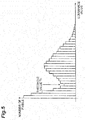
- FIG. 3 is a graph illustrating a one-dimensional distribution of pixel values of fluorescent image data to be processed by the identification unit 11 and FIGS. 4 and 5 are graphs illustrate histograms of luminance values of image data calculated by the identification unit 11.
- the identification unit 11 compares a pixel value of each pixel of the fluorescent image data with a preset threshold value Th to determine whether the pixel is a fluorescent pixel or a background pixel. Specifically, a pixel having a pixel value larger than the threshold value Th is identified as a fluorescent pixel, and a pixel having a pixel value smaller than or equal to the threshold value is identified as a background pixel.
- the threshold value Th is preset for each fluorescent image data in the following process so that the threshold value Th has a luminance value larger than a background noise level of the fluorescent image data.
- the identification unit 11 calculates a histogram of pixel values of ON image data used for creating fluorescent image data to be processed ( FIG. 4 ). Then, the identification unit 11 identifies a peak P 1 of a luminance value distribution of background light and a peak P 2 of a luminance value distribution of fluorescence, and sets the threshold value Th so that the threshold value Th becomes an intermediate luminance value between the peaks P 1 and P 2 .
- the identification unit 11 may set the threshold value Th by the following processing. That is, the identification unit 11 calculates a histogram of pixel values of fluorescent image data to be processed ( FIG. 5 ). Then, the identification unit 11 may identify the bottom of the luminance value distribution in the histogram and set the threshold value Th so that the threshold value Th becomes a luminance value at the bottom.
- the image processing unit 13 creates superimposed image data using the coefficient m indicating an adjustment ratio of a pixel value of a background image input from the input device 19. If a pixel value of a fluorescent image in fluorescent image data is larger than the pixel value of the background image in the background image data, that is, if luminance of the fluorescent image is higher than luminance of the background image, this coefficient m is set to 0 ⁇ m ⁇ 1. By using such a coefficient m, a pixel value of a background pixel of the superimposed image data becomes a value obtained by summing a pixel value of a background pixel of the fluorescent image data and a value obtained by multiplying a pixel value of a background pixel of the background image data by the coefficient m.
- a pixel value of a fluorescent pixel of the superimposed image data becomes a value obtained by summing a pixel value of a fluorescent pixel of the fluorescent image data and a pixel value of a fluorescent pixel of the background image data at a ratio of 1: 1.
- the image processing unit 13 calculates the following equation on the basis of background image data I b (x, y) (x and y are two-dimensional coordinates of a pixel on image data and I b indicates a pixel value of each pixel) and the coefficient m to calculate each pixel value I B (x, y) of the background image data of a superimposition source.
- I B x , y I b x , y ⁇ m
- the background image data of the superimposition source is created by multiplying the pixel values I b (x, y) of all of the pixels including the fluorescent pixel and the background pixel of the background image data by the coefficient m.
- the image processing unit 13 calculates the following equation on the basis of fluorescent image data I f (x, y), the background image data I b (x, y), and the coefficient m to calculate each pixel value I F (x, y) of the fluorescent image data of the superimposition source.
- I F x , y I f x , y + n ⁇ I b x , y ⁇ 1 ⁇ m
- the background image and the fluorescent image are superimposed at a luminance ratio of 1:1.
- the pixel value I SI (x, y) of the superimposed image data in the background pixel is set by a value calculated by the following equation.
- I SI x , y I b x , y ⁇ m + I f x , y ⁇ I b x , y ⁇ m
- the luminance of the background image is lowered corresponding to the coefficient m.
- the luminance value I f (x, y) in the background pixel is a noise level and becomes a negligible value.
- FIG. 6 is a flowchart illustrating a superimposed image data creation process by the fluorescent image acquisition system 1.
- a superimposed image of the observation object P is configured to be acquired in time series by iterating the process illustrated in FIG. 6 .
- step S01 an emission step
- ON image data is acquired from the imaging device 3 by the image processing unit 13 (step S02: an output step).
- step S03 an emission step
- step S03 an emission step
- OFF image data is acquired from the imaging device 3 by the image processing unit 13 (step S04: an output step). Thereafter, the image processing unit 13 calculates a difference between the ON image data and the OFF image data ("ON image data" - "OFF image data") to create fluorescent image data (step S05).
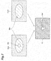
- FIG 7 is a diagram illustrating images G ON , G OFF , and G F of the ON image data, the OFF image data, and the fluorescent image data created by the fluorescent image acquisition system 1, respectively.
- the identification unit 11 identifies fluorescent pixels and background pixels among the pixels in the image data using the fluorescent image data (step S06: an identification step).
- the coefficient m for creating superimposed image data is set according to reading from the memory by the image processing unit 13 (step S07: a setting step).
- the image processing unit 13 creates background image data of a superimposition source on the basis of the background image data and the coefficient m (step S08: a calculation step).
- the image processing unit 13 creates fluorescent image data of the superimposition source on the basis of the background image data, the fluorescent image data, and the coefficient m (step S09: a calculation step).
- the background image data of the superimposition source and the fluorescent image data of the superimposition source are superimposed by the image processing unit 13 to create the superimposed image data (step S10: a calculation step).
- the superimposed image data is displayed on the display device 17.
- ON image data is acquired by capturing image of the observation object P in the ON period during which fluorescence is excited from the observation target P
- OFF image data is acquired by capturing image of the observation object P in the OFF period during which emission of the excitation light to the observation object P is stopped.
- fluorescent image data to which the fluorescent image is applied and background image data to which the background image is applied are created. Further, fluorescent pixels constituting the fluorescent image and background pixels other than the fluorescent pixels are identified among the plurality of pixels of the fluorescent image data.
- the fluorescent image acquisition system 1 it is possible to relatively adjust the luminance of the background image in accordance with the coefficient m with respect to the luminance of the fluorescent image, and maintain the luminance of the fluorescent image in the superimposed image. As a result, it is possible to evaluate an appropriate fluorescent image while highlighting the fluorescent image with respect to the background image, and it is possible to more easily recognize the fluorescent image in the superimposed image. Also, the pixel value of the pixel of the fluorescent image data is applied to the background pixel in the superimposed image. Thereby, it is possible to improve minuteness of the image in the vicinity of a boundary of the fluorescent image.
- the coefficient m is set to 0 ⁇ m ⁇ 1, it is possible to maintain the luminance of the fluorescent image while making the fluorescent image conspicuous with respect to the background image if the fluorescent image having a high pixel value (luminance) with respect to the background image is used.
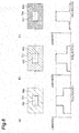
- FIG. 8 images of superimposed image data created by the fluorescent image acquisition system 1 with respect to the same observation object P under the same imaging conditions and one-dimensional luminance distributions of the superimposed image data when the coefficient m is set to various values are illustrated.
- fluorescent pixels and non-fluorescent pixels are identified by the identification unit 11 comparing pixel values of a plurality of pixels of fluorescent image data with a threshold value. According to such a configuration, it is possible to easily and accurately identify pixels included in a range of the fluorescent image using the fluorescent image data.
- the image processing unit 13 may use only background pixels as pixel data to be multiplied by a ratio of the coefficient m. Specifically, the image processing unit 13 calculates the following equation on the basis of the background image data I b (x, y), the coefficient m, and the parameter n to calculate each of the pixel values I B (x, y) of the background image data of the superimposition source.
- I B x , y I b x , y ⁇ m ⁇ 1 ⁇ n + I b x , y ⁇ n
- the image processing unit 13 sets each of the pixel values I F (x, y) of the fluorescent image data of the superimposition source by calculating the following equation using the fluorescent image data I f (x, y) itself.
- I F x , y I f x , y
- the image processing unit 13 creates superimposed image data by superimposing the background image data of the superimposition source and the fluorescent image data of the superimposition source.
- the pixel value I SI (x, y) of the superimposed image data in the fluorescent pixel is set to a value calculated by the following equation, and the background image and the fluorescent image are superimposed at a luminance ratio of 1:1.
- I SI x , y I b x , y + I f x , y
- the pixel value I SI (x, y) of the superimposed image data in the background pixel is set to a value calculated by the following equation, and the luminance of the background image is lowered corresponding to the coefficient m.
- I SI x , y I b x , y ⁇ m + I f x , y ⁇ I b x , y ⁇ m
- the coefficient m is set to 0 ⁇ m ⁇ 1, but is not limited to this value range. That is, if the pixel value of the fluorescent image in the fluorescent image data is smaller than the pixel value of the background image in the background image data, for example, if image data obtained by inverting the luminance value of the image data obtained from the image sensor 3b is processed, l ⁇ m may be set as the coefficient m.
- the fluorescent image data I F (x, y) of the superimposition source can be created by summing the pixel value I f (x, y) of each pixel and a pixel value of a fluorescent pixel of the background image data I b (x, y) whose ratio (l-m) is adjusted so that it is decreased in accordance with an increasing rate of the luminance indicated by the coefficient m.
- the fluorescent image acquisition system 1 is not limited to the form in which the camera unit 7 includes the imaging device 3 and the light emitting device 5, and the imaging device 3 and the light emitting device 5 may be adopted as separated devices.
- Switching ON/OFF of the emission of the excitation light L 1 by the light emitting device 5 is not limited to switching by the light source 5a, and the light emitting device 5 may include a shutter (not illustrated) that receives the excitation light L 1 emission from the light source 5a, and the ON/OFF of the emission of the excitation light L 1 toward the observation object P may be switched by the shutter.
- the superimposed image creation apparatus and the superimposed image creation method it is preferable to calculate values obtained by summing pixel values of non-fluorescent pixels of fluorescent image data and values obtained by multiplying pixel values of non-fluorescent pixels of background image data by a coefficient as pixel values of non-fluorescent pixels of a superimposed image in the image processing unit and the calculation step. If this configuration is provided, it is possible to improve minuteness of the image in the vicinity of a boundary of the fluorescent image because the fluorescent image data is applied to the non-fluorescent pixel in the superimposed image.
- the image processing unit and the creation step it is preferable to calculate a difference between first image data and second image data to create the fluorescent image data and create the background image data using the second image data. If this image processing unit is provided, it is possible to extract a fluorescent image in the fluorescent image data and create background image data including only a background image.
- the image processing unit and the calculation step it is preferable to multiply pixel values of the pixels including the fluorescent pixels and the non-fluorescent pixels of the background image data by the coefficient to create background image data of a superimposition source, sum pixel values of the fluorescent image data and pixel values of the fluorescent pixels of the background image data adjusted to be increased in accordance with a decreasing rate indicated by the coefficient to create fluorescent image data of the superimposition source, and superimpose background image data of a superimposition source and fluorescent image data of the superimposition source to create the superimposed image.
- the background image data of the superimposition source and the fluorescent image data of the superimposition source are superimposed, and a superimposed image in which values, which are obtained by summing pixel values of fluorescent pixels of the fluorescent image data and pixel values of fluorescent pixels of the background image data at a ratio of 1:1, are designated as pixel values of the fluorescent pixels and values, which are obtained by adding values obtained by multiplying pixel values of non-fluorescent pixels of the background image data by a coefficient to pixel values of non-fluorescent pixels of the fluorescent image data, are designated as pixel values of the non-fluorescent pixels can be created.
- the image processing unit and the calculation step it is preferable to multiply the pixel values of the non-fluorescent pixels of the background image data by the coefficient to create background image data of a superimposition source and superimpose the background image data of the superimposition source and the fluorescent image data to create the superimposed image.
- the background image data of the superimposition source and the fluorescent image data are superimposed and the superimposed image can be created by designating values, which are obtained by summing pixel values of fluorescent pixels of the fluorescent image data and pixel values of fluorescent pixels of the background image data at a ratio of 1:1, as pixel values of the fluorescent pixels and designating values, which are obtained by adding values obtained by multiplying pixel values of non-fluorescent pixels of the background image data by a coefficient to pixel values of non-fluorescent pixels of the fluorescent image data, as pixel values of the non-fluorescent pixels.
- the pixel value of the fluorescent image in the fluorescent image data be greater than the pixel value of the background image in the background image data.
- the pixel value of the fluorescent image in the fluorescent image data be less than the pixel value of the background image in the background image data.
- pixel values of the plurality of pixels of the fluorescent image data are compared with a threshold value to identify the fluorescent pixel and the non-fluorescent pixel. In this manner, it is possible to easily and accurately identify pixels included in a range of a fluorescent image using fluorescent image data.
- a form of the present invention is applied to a superimposed image creation apparatus and a superimposed image creation method for creating an image in which a background image is superimposed on a fluorescent image of an object to be measured. According to the present invention, it is possible to more easily recognize the fluorescent image in the superimposed image in which the fluorescent image and the background image are superimposed.
Landscapes
- Health & Medical Sciences (AREA)
- Life Sciences & Earth Sciences (AREA)
- Physics & Mathematics (AREA)
- Surgery (AREA)
- Engineering & Computer Science (AREA)
- General Health & Medical Sciences (AREA)
- Pathology (AREA)
- Nuclear Medicine, Radiotherapy & Molecular Imaging (AREA)
- Optics & Photonics (AREA)
- Heart & Thoracic Surgery (AREA)
- Veterinary Medicine (AREA)
- Biomedical Technology (AREA)
- Biophysics (AREA)
- Medical Informatics (AREA)
- Molecular Biology (AREA)
- Animal Behavior & Ethology (AREA)
- Public Health (AREA)
- Radiology & Medical Imaging (AREA)
- General Physics & Mathematics (AREA)
- Chemical & Material Sciences (AREA)
- Analytical Chemistry (AREA)
- Signal Processing (AREA)
- Biochemistry (AREA)
- Immunology (AREA)
- Theoretical Computer Science (AREA)
- Investigating, Analyzing Materials By Fluorescence Or Luminescence (AREA)
- Endoscopes (AREA)
Abstract
Description
- The present invention relates to a superimposed image creation apparatus and a superimposed image creation method for creating an image in which a background image is superimposed on a fluorescent image of an object to be measured.
- Observation devices for observing a fluorescent image generated in accordance with emission of excitation light from a living body or the like have been used conventionally. In such observation devices, an image obtained by capturing a reflected image generated by illumination light and an image obtained by capturing the fluorescent image generated by the excitation light are superimposed. For example, the following Patent Literature 1 describes a configuration in which a balance between a fluorescent image and a reflected image is adjusted by superimposing image data of a binned fluorescent image and image data of a reflected image. Also, in the following Patent Literature 2, a process of creating an image of a fluorescent image by assigning data to which an estimated fluorescence yield or the like is added to a pixel value and outputting an observation image by superimposing the image and a reflected image is described.
-
- [Patent Literature 1] Japanese Patent No.
5355799 - [Patent Literature 2] Japanese Unexamined Patent Publication No.
2009-279172 - However, in the devices described in the above-described Patent Literatures 1 and 2, superimposition is performed by generally adjusting a balance between an image obtained by capturing a fluorescent image and an image obtained by capturing a background image. Thus, it may be difficult to recognize the fluorescent image itself in a superimposed image when luminance of the fluorescent image is low.
- Therefore, the present invention has been made in view of such a problem, and an objective of the invention is to provide a superimposed image creation apparatus and a superimposed image creation method for further facilitating recognition of a fluorescent image in a superimposed image in which the fluorescent image and a background image are superimposed.
- To solve the above-described problem, a superimposed image creation apparatus according to an embodiment of the present invention is an apparatus for creating a fluorescent image by imaging fluorescence emitted from an object and creating a superimposed image by superimposing a background image on the fluorescent image, the apparatus including: a light irradiating unit for emitting excitation light toward the object during a first period and stopping the emission of the excitation light during a second period different from the first period; a capturing unit having a plurality of pixels that are two-dimensionally arranged and for outputting first image data and second image data by capturing image of the object during each of the first period and the second period; a coefficient setting unit for setting a coefficient for adjusting a luminance value of the background image in the superimposed image; an image processing unit for creating fluorescent image data including the fluorescent image and background image data including the background image on the basis of the first image data and the second image data; and an identification unit for identifying fluorescent pixels, which are pixels constituting the fluorescent image, and non-fluorescent pixels, which are pixels other than the fluorescent pixels, among the plurality of pixels using the fluorescent image data, wherein the image processing unit is configured to calculate values, which are obtained by summing pixel values of the fluorescent pixels of the fluorescent image data and pixel values of the fluorescent pixels of the background image data at a ratio of 1:1, as pixel values of the fluorescent pixels of the superimposed image and calculate values, which are obtained by multiplying at least pixel values of the non-fluorescent pixels of the background image data by the coefficient, as pixel values of the non-fluorescent pixels of the superimposed image to create the superimposed image.
- Alternatively, a superimposed image creation method according to another embodiment of the present invention is a method of creating a fluorescent image by imaging fluorescence emitted from an object and creating a superimposed image by superimposing a background image on the fluorescent image, the method including the steps of: emitting excitation light toward the object during a first period and stopping the emission of the excitation light during a second period different from the first period (an emission step); outputting first image data and second image data by capturing image of the object during each of the first period and the second period using an image sensor having a plurality of pixels that are two-dimensionally arranged (an output step); setting a coefficient for adjusting a luminance value of the background image in the superimposed image (a setting step); creating fluorescent image data including the fluorescent image and background image data including the background image on the basis of the first image data and the second image data (a creation step); identifying fluorescent pixels, which are pixels constituting the fluorescent image, and non-fluorescent pixels, which are pixels other than the fluorescent pixels, among the plurality of pixels using the fluorescent image data (an identification step); and calculating values, which are obtained by summing pixel values of the fluorescent pixels of the fluorescent image data and pixel values of the fluorescent pixels of the background image data at a ratio of 1:1, as pixel values of the fluorescent pixels of the superimposed image and calculating values, which are obtained by multiplying at least pixel values of the non-fluorescent pixels of the background image data by the coefficient, as pixel values of the non-fluorescent pixels of the superimposed image to create the superimposed image (a calculation step).
- According to the superimposed image creation apparatus or the superimposed image creation method of the above-described embodiment, the first image data is acquired by capturing image of the object in the first period during which the excitation light is emitted toward the object, the second image data is acquired by capturing image of the object in the second period during which no excitation light is emitted toward the object, and the fluorescent image data to which the fluorescent image is applied and the background image data to which the background image is applied are created on the basis of the first and second image data. Further, the fluorescent pixels constituting the fluorescent image and the non-fluorescent pixels other than the fluorescent pixels are identified among the plurality of pixels of the fluorescent image data, and the superimposed image is created so that values, which are obtained by summing pixel values of the fluorescent pixels of the fluorescent image data and pixel values of the fluorescent pixels of the background image data at a ratio of 1:1, are designated as the pixel values of the fluorescent pixels and values, which are obtained by multiplying at least pixel values of the non-fluorescent pixels of the background image data by the coefficient, are designated as the pixel values of the non-fluorescent pixels. According to this configuration, it is possible to relatively adjust luminance of the background image with respect to luminance of the fluorescent image in the superimposed image, conspicuously maintain the luminance of the fluorescent image with respect to the background image, and more easily recognize the fluorescent image in the superimposed image.
- According to a form of the present invention, it is possible to further facilitate recognition of a fluorescent image in a superimposed image in which the fluorescent image and a background image are superimposed.
-
-
FIG. 1 is a block diagram illustrating a schematic configuration of a fluorescent image acquisition system 1 according to a preferred embodiment of the present invention. -
FIG. 2 is a timing chart illustrating timings of various operations controlled by acamera controller 15 ofFIG 1 . -
FIG. 3 is a graph illustrating a one-dimensional distribution of pixel values of fluorescent image data of a processing object of anidentification unit 11 ofFIG. 1 . -
FIG. 4 is a graph illustrating a histogram of a luminance value of ON image data calculated by theidentification unit 11 ofFIG 1 . -
FIG. 5 is a graph illustrating a histogram of a luminance value of fluorescent image data calculated by theidentification unit 11 ofFIG. 1 . -
FIG 6 is a flowchart illustrating a procedure of a superimposed image data creation process by the fluorescent image acquisition system 1 ofFIG. 1 . -
FIG. 7 is a diagram illustrating images of ON image data, OFF image data, and fluorescent image data created by the fluorescent image acquisition system 1 ofFIG. 1 . -
FIG. 8 is a diagram illustrating an image of superimposed image data created by the fluorescent image acquisition system 1 and a one-dimensional luminance distribution of superimposed image data thereof when a coefficient m is set to various values. - Hereinafter, preferred embodiments of a superimposed image creation apparatus and a superimposed image creation method according to the present invention will be described in detail with reference to the accompanying drawings. In the description of the drawings, the same or corresponding parts are denoted by the same reference numerals, and redundant descriptions thereof will be omitted.
-
FIG. 1 is a block diagram illustrating a schematic configuration of a fluorescent image acquisition system 1 according to a preferred embodiment of the present invention. The fluorescent image acquisition system 1 illustrated inFIG. 1 is configured so that a user can observe an observation object P in a moving image by acquiring observation images of the observation object P in a time series at a predetermined frame rate. The observation object P is, for example, a biological tissue to which a fluorescent dye, such as indocyanine green, has been introduced in advance. If the fluorescent image acquisition system 1 is used, it is possible to observe how the fluorescent dye flows through blood vessels, lymph vessels, and the like of a living body and how a fluorescent pigment is accumulated in organs and lymph nodes in the living body. The fluorescent image acquisition system 1, which is one form of superimposed image creation apparatus, includes acamera unit 7 having an imaging device (capturing unit) 3 and a light emitting device (light irradiating unit) 5 built therein, acamera controller 15 electrically connected to thecamera unit 7 and having acontrol unit 9 for controlling thecamera unit 7 and anidentification unit 11 and animage processing unit 13 for processing image data output from thecamera unit 7, and adisplay device 17, aninput device 19, and astorage device 21 electrically connected to the camera controller. - The
light emitting device 5 includes alight source 5a that emits excitation light L1 for exciting a fluorescent dye for fluorescence observation of the observation object P and a lightsource control unit 5b that controls ON/OFF of the emission of the excitation light L1 of thelight source 5a built therein. Thelight source 5a is a light emitting element such as a light emitting diode (LED), a laser diode (LD), or a super luminescent diode (SLD) and emits light having a wavelength that excites a fluorescent dye. The lightsource control unit 5b is a control circuit that alternately and iteratively switches ON (an output state) and OFF (an output stop state) of the excitation light emission of thelight source 5a under the control of thecamera controller 15 electrically connected to thecamera unit 7. Also, it is preferable that the wavelength of the light emitted from thelight source 5a not include a wavelength of fluorescence. If the wavelength of the light emitted from thelight source 5a includes the wavelength of fluorescence, thelight emitting device 5 may include an optical filter (not illustrated) that blocks light having the same wavelength as the wavelength of the fluorescence of light emitted from thelight source 5a. - The
imaging device 3 is a device for capturing an optical image of the observation object P under the control of thecamera controller 15. Theimaging device 3 is configured to include anoptical filter 3a that passes light of a wavelength of fluorescence L2 emitted from the fluorescent dye and blocks light of a wavelength of the excitation light L1, animage sensor 3b that receives the fluorescence L2 passing through theoptical filter 3a and background light, which is light from a background of a fluorescent image of the observation object P, and outputs image data by photoelectrically converting the light, and animaging control unit 3c that adjusts an exposure timing and an exposure time of theimage sensor 3b under the control of thecamera controller 15. Theimage sensor 3b is an area image sensor such as a CCD image sensor or a CMOS image sensor, and includes a plurality of pixels (photoelectric conversion elements) that are two-dimensionally arranged. Theoptical filter 3a is configured to pass not only light having the wavelength of the fluorescence L2 but also light of a wavelength of reflected light generated in the observation object P by illumination light emitted from an external illumination device. Thus, theimage sensor 3b receives reflected light from the observation object P as background light. - In the
camera unit 7 having the above-described configuration, theimage sensor 3b receives (images) the fluorescence from the observation object P and the background light, and outputs ON image data as image data in accordance with the received (imaged) fluorescence and background light in a period during which the excitation light emission of thelight source 5a is ON (hereinafter simply referred to as an "ON period"). On the other hand, theimage sensor 3b receives (images) the background light from the observation object P and outputs OFF image data as image data in accordance with the received (imaged) background light in a period during which the excitation light emission of thelight source 5a is OFF (hereinafter simply referred to as an "OFF period"). If the frame rate of the image data output from thecamera unit 7 is set to, for example, 30 frames/sec, theimaging control unit 3c performs control so that the exposure time is, for example, 30 msec. If the frame rate is adjusted within a range of 15 frames/sec to 1000 frames/sec according to a setting change of thecamera unit 7, theimaging control unit 3c performs control so that the exposure time is variable within a range of 60 msec to 1 msec in accordance therewith. - The
camera controller 15 is a data processing device including an arithmetic processing circuit such as a field programmable gate array (FPGA) or a central processing unit (CPU), a memory, and the like, and thecontrol unit 9, theidentification unit 11, and theimage processing unit 13 are functionally mounted in the data processing device. However, thecontrol unit 9, theidentification unit 11, and theimage processing unit 13 are not limited to the case in which they are configured within the same device, and may be configured to be distributed in a plurality of devices. - The
control unit 9 of thecamera controller 15 controls operations of theimaging device 3 and thelight emitting device 5. That is, thecontrol unit 9 controls ON/OFF of the excitation light emission by thelight emitting device 5 and the exposure timing of theimage sensor 3b so that they are synchronized (details thereof will be described below). Theimage processing unit 13 of thecamera controller 15 performs image processing on the ON image data and the OFF image data output from theimage sensor 3b to create fluorescent image data, which includes a fluorescent image to which a fluorescence distribution is applied among optical images from the observation object P, and background image data, which includes a background image to which a background distribution is applied among the optical images from the observation object P. Specifically, theimage processing unit 13 calculates a difference at the same pixel position of each piece of image data between the ON image data and the OFF image data ("ON image data" - "OFF image data") to create the fluorescent image data. Also, theimage processing unit 13 creates the background image data using the OFF image data as it is. Further, theimage processing unit 13 uses the fluorescent image data and the background image data to create superimposed image data to which an image, in which the background image from the observation object P and the fluorescent image from the observation object P are superimposed, is applied, and outputs the created superimposed image data as output image data to thedisplay device 17 and the storage device 21 (details of the superimposed image creation method will be described below). Using the fluorescent image data created by theimage processing unit 13, theidentification unit 11 of thecamera controller 15 identifies fluorescent pixels, which are pixels constituting a fluorescent image, and background pixels (non-fluorescent pixels), which are pixels other than the fluorescent pixels, among a plurality of pixels included in the image data (details of the pixel identification method will be described below). Then, theidentification unit 11 delivers information about the identified pixels to theimage processing unit 13. - The
display device 17 is an image output device such as a display device connected to thecamera controller 15 and displays display image data output from theimage processing unit 13. Also, theinput device 19 is a data input device such as a keyboard, a mouse, or a touch panel display connected to thecamera controller 15 and inputs parameters for designating imaging conditions in thecamera unit 7 and parameters indicating conditions of image processing in theimage processing unit 13. Also, the function of theinput device 19 may be provided in thecamera unit 7 or thecamera controller 15 by providing a button or the like in thecamera unit 7 or thecamera controller 15. For example, theinput device 19 receives setting inputs of an exposure time of theimaging device 3, an emission intensity of thelight emitting device 5, and a coefficient m indicating an adjustment ratio of a pixel value of the background image when the superimposed image is created in theimage processing unit 13. Further, theinput device 19 sets the received parameters in thecamera controller 15. That is, theinput device 19 functions as a coefficient setting unit that sets the coefficient m. Also, thestorage device 21 is a data storage device connected to thecamera controller 15 and stores display image data, various types of image data that are processed by thecamera controller 15, and various types of parameters that are set by theinput device 19. - Here, a temporal relationship of an ON/OFF timing of the excitation light emission of the
light source 5a, the exposure timing of theimage sensor 3b, and a creation timing of the fluorescent image data by theimage processing unit 13 will be described with reference toFIG. 2. FIG. 2 is a timing chart illustrating timings of various operations controlled by thecamera controller 15. Part (a) inFIG. 2 illustrates an ON/OFF timing of the excitation light emission of thelight source 5a, part (b) inFIG. 2 illustrates the exposure timing of theimage sensor 3b, part (c) inFIG. 2 illustrates a saving timing of the image data of theimage processing unit 13, and part (d) inFIG. 2 illustrates the creation timing of the fluorescent image data of theimage processing unit 13. - As illustrated in parts (a) and (b) in
FIG. 2 , thecontrol unit 9 controls the ON/OFF timing of the excitation light of thelight source 5a so that the ON period and the OFF period are alternately iterated in synchronization with an exposure period of one frame of theimage sensor 3b. That is, a length of the ON period and a length of the OFF period are substantially the same as a length of the exposure period, and the OFF period is set to be a period different from the ON period. Then, theimage processing unit 13 acquires image data output on the basis of an electric charge accumulated in accordance with an exposure of theimage sensor 3b in the ON period as ON image data A. Thereafter, theimage processing unit 13 acquires image data output on the basis of an electric charge accumulated in accordance with an exposure of theimage sensor 3b in the subsequent OFF period as OFF image data B. At this time, the first ON image data A is stored in the memory in theimage processing unit 13 at a time of acquisition, and then OFF image data B acquired thereafter is input to a difference circuit in theimage processing unit 13 and saved in the memory. The ON image data A in the memory is also input to the difference circuit at a timing at which the OFF image data B is input to the difference circuit so that a difference between the two pieces of image data is calculated and fluorescent image data A-B is created. Subsequently, subsequently obtained ON image data A' is input to the difference circuit and saved in the memory. The OFF image data B in the memory is also input to the difference circuit at a timing at which the ON image data A' is input to the difference circuit so that a difference between the two pieces of image data is calculated and fluorescent image data A'-B is created. By iterating such processing, theimage processing unit 13 can acquire time-series fluorescent image data for each exposure period (frame) of theimage sensor 3b. - Next, details of the pixel identification process performed by the
identification unit 11 of thecamera controller 15 will be described.FIG. 3 is a graph illustrating a one-dimensional distribution of pixel values of fluorescent image data to be processed by theidentification unit 11 andFIGS. 4 and5 are graphs illustrate histograms of luminance values of image data calculated by theidentification unit 11. - With respect to fluorescent image data having a one-dimensional distribution of pixel values illustrated in
FIG. 3 , theidentification unit 11 compares a pixel value of each pixel of the fluorescent image data with a preset threshold value Th to determine whether the pixel is a fluorescent pixel or a background pixel. Specifically, a pixel having a pixel value larger than the threshold value Th is identified as a fluorescent pixel, and a pixel having a pixel value smaller than or equal to the threshold value is identified as a background pixel. The threshold value Th is preset for each fluorescent image data in the following process so that the threshold value Th has a luminance value larger than a background noise level of the fluorescent image data. - That is, the
identification unit 11 calculates a histogram of pixel values of ON image data used for creating fluorescent image data to be processed (FIG. 4 ). Then, theidentification unit 11 identifies a peak P1 of a luminance value distribution of background light and a peak P2 of a luminance value distribution of fluorescence, and sets the threshold value Th so that the threshold value Th becomes an intermediate luminance value between the peaks P1 and P2. - Further, the
identification unit 11 may set the threshold value Th by the following processing. That is, theidentification unit 11 calculates a histogram of pixel values of fluorescent image data to be processed (FIG. 5 ). Then, theidentification unit 11 may identify the bottom of the luminance value distribution in the histogram and set the threshold value Th so that the threshold value Th becomes a luminance value at the bottom. - Next, details of a superimposed image data creation method by the
image processing unit 13 will be described. - The
image processing unit 13 creates superimposed image data using the coefficient m indicating an adjustment ratio of a pixel value of a background image input from theinput device 19. If a pixel value of a fluorescent image in fluorescent image data is larger than the pixel value of the background image in the background image data, that is, if luminance of the fluorescent image is higher than luminance of the background image, this coefficient m is set to 0≤m≤1. By using such a coefficient m, a pixel value of a background pixel of the superimposed image data becomes a value obtained by summing a pixel value of a background pixel of the fluorescent image data and a value obtained by multiplying a pixel value of a background pixel of the background image data by the coefficient m. On the other hand, a pixel value of a fluorescent pixel of the superimposed image data becomes a value obtained by summing a pixel value of a fluorescent pixel of the fluorescent image data and a pixel value of a fluorescent pixel of the background image data at a ratio of 1: 1. Thereby, in the superimposed image data, luminance of the background light can be lowered in accordance with the coefficient m in a background portion of the fluorescent image, and luminance of the fluorescence and the luminance of the background light can be superimposed at a ratio of 1: 1 in a fluorescent image portion. - More specifically, the
image processing unit 13 calculates the following equation on the basis of background image data Ib(x, y) (x and y are two-dimensional coordinates of a pixel on image data and Ib indicates a pixel value of each pixel) and the coefficient m to calculate each pixel value IB(x, y) of the background image data of a superimposition source.
- That is, the background image data of the superimposition source is created by multiplying the pixel values Ib(x, y) of all of the pixels including the fluorescent pixel and the background pixel of the background image data by the coefficient m.
- Subsequently, the
image processing unit 13 calculates the following equation on the basis of fluorescent image data If(x, y), the background image data Ib(x, y), and the coefficient m to calculate each pixel value IF(x, y) of the fluorescent image data of the superimposition source.
- Here, the parameter n in the above-described equation is assigned n=1 in the fluorescent pixel and n=0 in the background pixel, and is set on the basis of a result of a pixel identification process by the
identification unit 11. That is, the pixel value If(x, y) of each pixel of the fluorescent image data and a pixel value of a fluorescent pixel of the background image data Ib(x, y) whose ratio (1-m) is adjusted so that the pixel value increases in accordance with a decreasing rate of luminance indicated by the coefficient m are summed to create the fluorescent image data of the superimposition source. Thereby, it is possible to compensate for a decrease in the pixel value of the background image data of the superimposition source in the fluorescent pixel by using the pixel value of the fluorescent image data of the superimposition source. - Further, the
image processing unit 13 creates superimposed image data by superimposing the background image data of the superimposition source and the fluorescent image data of the superimposition source. Specifically, the pixel value IB(x, y) of each pixel of the background image data of the superimposition source and each of the pixel values IF(x, y) of the fluorescent image data of the superimposition source are summed. Thereby, a pixel value ISI(x, y) of the superimposed image data in the fluorescent pixel is set by a value calculated by the following equation.
- The background image and the fluorescent image are superimposed at a luminance ratio of 1:1. On the other hand, the pixel value ISI(x, y) of the superimposed image data in the background pixel is set by a value calculated by the following equation.

- The luminance of the background image is lowered corresponding to the coefficient m. Here, the luminance value If(x, y) in the background pixel is a noise level and becomes a negligible value.
- Hereinafter, a procedure of the superimposed image data creation process by the above-described fluorescent image acquisition system 1 will be described and the superimposed image data creation method of the present embodiment will be described in detail.
FIG. 6 is a flowchart illustrating a superimposed image data creation process by the fluorescent image acquisition system 1. In the fluorescent image acquisition system 1, a superimposed image of the observation object P is configured to be acquired in time series by iterating the process illustrated inFIG. 6 . - First, when the superimposed image acquisition process is started by an instruction input by a user, excitation light from the
light source 5a is emitted toward the observation object P to which a fluorescent dye is introduced at a timing (during an ON period) synchronized with an exposure period of theimage sensor 3b (step S01: an emission step). In synchronization with this, ON image data is acquired from theimaging device 3 by the image processing unit 13 (step S02: an output step). Subsequently, the emission of the excitation light from thelight source 5a is stopped (step S03: an emission step) at a timing (during an OFF period) synchronized with a next exposure period of theimage sensor 3b. In synchronization with this, OFF image data is acquired from theimaging device 3 by the image processing unit 13 (step S04: an output step). Thereafter, theimage processing unit 13 calculates a difference between the ON image data and the OFF image data ("ON image data" - "OFF image data") to create fluorescent image data (step S05).FIG 7 is a diagram illustrating images GON, GOFF, and GF of the ON image data, the OFF image data, and the fluorescent image data created by the fluorescent image acquisition system 1, respectively. By taking a difference between the ON image GON including a fluorescent image IMF and a background image IMB and the OFF image GOFF including the background image IMB as described above, it is possible to obtain fluorescent image data to which the fluorescent image IMF is applied. - Next, the
identification unit 11 identifies fluorescent pixels and background pixels among the pixels in the image data using the fluorescent image data (step S06: an identification step). Also, the coefficient m for creating superimposed image data is set according to reading from the memory by the image processing unit 13 (step S07: a setting step). Subsequently, theimage processing unit 13 creates background image data of a superimposition source on the basis of the background image data and the coefficient m (step S08: a calculation step). In addition, theimage processing unit 13 creates fluorescent image data of the superimposition source on the basis of the background image data, the fluorescent image data, and the coefficient m (step S09: a calculation step). Finally, the background image data of the superimposition source and the fluorescent image data of the superimposition source are superimposed by theimage processing unit 13 to create the superimposed image data (step S10: a calculation step). The superimposed image data is displayed on thedisplay device 17. - According to the above-described fluorescent image acquisition system 1, ON image data is acquired by capturing image of the observation object P in the ON period during which fluorescence is excited from the observation target P, and OFF image data is acquired by capturing image of the observation object P in the OFF period during which emission of the excitation light to the observation object P is stopped. On the basis of the ON image data and the OFF image data, fluorescent image data to which the fluorescent image is applied and background image data to which the background image is applied are created. Further, fluorescent pixels constituting the fluorescent image and background pixels other than the fluorescent pixels are identified among the plurality of pixels of the fluorescent image data. Thereafter, a superimposed image in which values, which are obtained by summing pixel values of the fluorescent pixels of the fluorescent image data and pixel values of the fluorescent pixels of the background image data at a ratio of 1:1, are designated as pixel values of the fluorescent pixels and values, which are obtained by adding values obtained by multiplying pixel values of background pixels of the background image data by the coefficient m to pixel values of background pixels of the fluorescent image data, are designated as pixel values of the background pixels is created. Generally, there is a technique of increasing luminance of a fluorescent image as a technique of making a fluorescent image conspicuous with respect to a background image. However, this technique has a problem in that a distribution of a fluorescent dye may not be properly ascertained. On the other hand, according to the configuration of the fluorescent image acquisition system 1, it is possible to relatively adjust the luminance of the background image in accordance with the coefficient m with respect to the luminance of the fluorescent image, and maintain the luminance of the fluorescent image in the superimposed image. As a result, it is possible to evaluate an appropriate fluorescent image while highlighting the fluorescent image with respect to the background image, and it is possible to more easily recognize the fluorescent image in the superimposed image. Also, the pixel value of the pixel of the fluorescent image data is applied to the background pixel in the superimposed image. Thereby, it is possible to improve minuteness of the image in the vicinity of a boundary of the fluorescent image.
- Also, because the coefficient m is set to 0≤m≤1, it is possible to maintain the luminance of the fluorescent image while making the fluorescent image conspicuous with respect to the background image if the fluorescent image having a high pixel value (luminance) with respect to the background image is used. In
FIG. 8 , images of superimposed image data created by the fluorescent image acquisition system 1 with respect to the same observation object P under the same imaging conditions and one-dimensional luminance distributions of the superimposed image data when the coefficient m is set to various values are illustrated. An image of superimposed image data created when the coefficient m=1 and a luminance distribution of a one-dimensional direction of pixels in a dotted line direction of the superimposed image data are illustrated in part (a) ofFIG. 8 . An image of superimposed image data created when the coefficient m=1/2 and a luminance distribution of a one-dimensional direction in a dotted line direction of the superimposed image data are illustrated in part (b) ofFIG. 8 . An image of superimposed image data created when the coefficient m=1/4 and a luminance distribution of a one-dimensional direction in a dotted line direction of the superimposed image data are illustrated in part (c) ofFIG. 8 . Because a ratio of luminance of background light in a superimposed image can be adjusted in accordance with the coefficient m as described above, it is easy to recognize the fluorescent image IMF. On the other hand, because luminance of the fluorescent image IMF is made constant irrespective of a set value of the coefficient m, it is possible to appropriately evaluate the fluorescent image IMF. - Further, fluorescent pixels and non-fluorescent pixels are identified by the
identification unit 11 comparing pixel values of a plurality of pixels of fluorescent image data with a threshold value. According to such a configuration, it is possible to easily and accurately identify pixels included in a range of the fluorescent image using the fluorescent image data. - Also, the present invention is not limited to the above-described embodiment.
- For example, various other methods can be adopted as a superimposed image data creation method by the
image processing unit 13. That is, in a modified example of the present invention, theimage processing unit 13 may use only background pixels as pixel data to be multiplied by a ratio of the coefficient m. Specifically, theimage processing unit 13 calculates the following equation on the basis of the background image data Ib(x, y), the coefficient m, and the parameter n to calculate each of the pixel values IB(x, y) of the background image data of the superimposition source.
- That is, adjustment is performed by multiplying the pixel value Ib(x, y) of the background pixel of the background image data by the coefficient m, and hence the background image data of the superimposition source is created.
- Subsequently, the
image processing unit 13 sets each of the pixel values IF(x, y) of the fluorescent image data of the superimposition source by calculating the following equation using the fluorescent image data If(x, y) itself.
- Further, the
image processing unit 13 creates superimposed image data by superimposing the background image data of the superimposition source and the fluorescent image data of the superimposition source. Thereby, the pixel value ISI(x, y) of the superimposed image data in the fluorescent pixel is set to a value calculated by the following equation, and the background image and the fluorescent image are superimposed at a luminance ratio of 1:1.
- On the other hand, the pixel value ISI(x, y) of the superimposed image data in the background pixel is set to a value calculated by the following equation, and the luminance of the background image is lowered corresponding to the coefficient m.

- Further, in the above-described embodiment, the coefficient m is set to 0≤m≤1, but is not limited to this value range. That is, if the pixel value of the fluorescent image in the fluorescent image data is smaller than the pixel value of the background image in the background image data, for example, if image data obtained by inverting the luminance value of the image data obtained from the
image sensor 3b is processed, l≤m may be set as the coefficient m. In the above-described embodiment, by using such a coefficient m, the fluorescent image data IF(x, y) of the superimposition source can be created by summing the pixel value If(x, y) of each pixel and a pixel value of a fluorescent pixel of the background image data Ib(x, y) whose ratio (l-m) is adjusted so that it is decreased in accordance with an increasing rate of the luminance indicated by the coefficient m. Thereby, it is possible to compensate for an increased pixel value of the background image data of the superimposition source in a fluorescent pixel by using a pixel value of the fluorescent image data of the superimposition source. - Also, the fluorescent image acquisition system 1 is not limited to the form in which the
camera unit 7 includes theimaging device 3 and thelight emitting device 5, and theimaging device 3 and thelight emitting device 5 may be adopted as separated devices. Switching ON/OFF of the emission of the excitation light L1 by thelight emitting device 5 is not limited to switching by thelight source 5a, and thelight emitting device 5 may include a shutter (not illustrated) that receives the excitation light L1 emission from thelight source 5a, and the ON/OFF of the emission of the excitation light L1 toward the observation object P may be switched by the shutter. - Here, in the superimposed image creation apparatus and the superimposed image creation method, it is preferable to calculate values obtained by summing pixel values of non-fluorescent pixels of fluorescent image data and values obtained by multiplying pixel values of non-fluorescent pixels of background image data by a coefficient as pixel values of non-fluorescent pixels of a superimposed image in the image processing unit and the calculation step. If this configuration is provided, it is possible to improve minuteness of the image in the vicinity of a boundary of the fluorescent image because the fluorescent image data is applied to the non-fluorescent pixel in the superimposed image.
- Also, in the image processing unit and the creation step, it is preferable to calculate a difference between first image data and second image data to create the fluorescent image data and create the background image data using the second image data. If this image processing unit is provided, it is possible to extract a fluorescent image in the fluorescent image data and create background image data including only a background image.
- Further, in the image processing unit and the calculation step, it is preferable to multiply pixel values of the pixels including the fluorescent pixels and the non-fluorescent pixels of the background image data by the coefficient to create background image data of a superimposition source, sum pixel values of the fluorescent image data and pixel values of the fluorescent pixels of the background image data adjusted to be increased in accordance with a decreasing rate indicated by the coefficient to create fluorescent image data of the superimposition source, and superimpose background image data of a superimposition source and fluorescent image data of the superimposition source to create the superimposed image. In this case, the background image data of the superimposition source and the fluorescent image data of the superimposition source are superimposed, and a superimposed image in which values, which are obtained by summing pixel values of fluorescent pixels of the fluorescent image data and pixel values of fluorescent pixels of the background image data at a ratio of 1:1, are designated as pixel values of the fluorescent pixels and values, which are obtained by adding values obtained by multiplying pixel values of non-fluorescent pixels of the background image data by a coefficient to pixel values of non-fluorescent pixels of the fluorescent image data, are designated as pixel values of the non-fluorescent pixels can be created.
- Further, in the image processing unit and the calculation step, it is preferable to multiply the pixel values of the non-fluorescent pixels of the background image data by the coefficient to create background image data of a superimposition source and superimpose the background image data of the superimposition source and the fluorescent image data to create the superimposed image. According to this configuration, the background image data of the superimposition source and the fluorescent image data are superimposed and the superimposed image can be created by designating values, which are obtained by summing pixel values of fluorescent pixels of the fluorescent image data and pixel values of fluorescent pixels of the background image data at a ratio of 1:1, as pixel values of the fluorescent pixels and designating values, which are obtained by adding values obtained by multiplying pixel values of non-fluorescent pixels of the background image data by a coefficient to pixel values of non-fluorescent pixels of the fluorescent image data, as pixel values of the non-fluorescent pixels.
- Further, it is preferable that the pixel value of the fluorescent image in the fluorescent image data be greater than the pixel value of the background image in the background image data. In the coefficient setting unit and the setting step, it is preferable to set the coefficient to a value greater than or equal to 0 and less than or equal to 1. According to this configuration, if image data of the fluorescent image having a larger pixel value than that of the background image is used, it is possible to conspicuously maintain luminance of a fluorescent image with respect to a background image.
- Also, it is preferable that the pixel value of the fluorescent image in the fluorescent image data be less than the pixel value of the background image in the background image data. In the coefficient setting unit and the setting step, it is preferable to set the coefficient to a value greater than or equal to 1. In this case, if image data of the fluorescent image having a smaller pixel value than that of the background image is used, it is possible to conspicuously maintain luminance of a fluorescent image with respect to a background image.
- Further, in the identification unit and the identification step, pixel values of the plurality of pixels of the fluorescent image data are compared with a threshold value to identify the fluorescent pixel and the non-fluorescent pixel. In this manner, it is possible to easily and accurately identify pixels included in a range of a fluorescent image using fluorescent image data.
- A form of the present invention is applied to a superimposed image creation apparatus and a superimposed image creation method for creating an image in which a background image is superimposed on a fluorescent image of an object to be measured. According to the present invention, it is possible to more easily recognize the fluorescent image in the superimposed image in which the fluorescent image and the background image are superimposed.
-
- 1
- Fluorescent image acquisition system
- 3
- Imaging device (capturing unit)
- 5
- Light emitting device (light irradiating unit)
- 11
- Identification unit
- 13
- Image processing unit
- 19
- Input device (coefficient setting unit)
- P
- Observation object
Claims (9)
- A superimposed image creation apparatus for creating a fluorescent image by imaging fluorescence emitted from an object and creating a superimposed image by superimposing a background image on the fluorescent image, the superimposed image creation apparatus comprising:a light irradiating unit for emitting excitation light toward the object during a first period and stopping the emission of the excitation light during a second period different from the first period;a capturing unit having a plurality of pixels that are two-dimensionally arranged and for outputting first image data and second image data by capturing image of the object during each of the first period and the second period;a coefficient setting unit for setting a coefficient for adjusting a luminance value of the background image in the superimposed image;an image processing unit for creating fluorescent image data including the fluorescent image and background image data including the background image on the basis of the first image data and the second image data; andan identification unit for identifying fluorescent pixels, which are pixels constituting the fluorescent image, and non-fluorescent pixels, which are pixels other than the fluorescent pixels, among the plurality of pixels using the fluorescent image data,wherein the image processing unit is configured to calculate values, which are obtained by summing pixel values of the fluorescent pixels of the fluorescent image data and pixel values of the fluorescent pixels of the background image data at a ratio of 1:1, as pixel values of the fluorescent pixels of the superimposed image and calculate values, which are obtained by multiplying at least pixel values of the non-fluorescent pixels of the background image data by the coefficient, as pixel values of the non-fluorescent pixels of the superimposed image to create the superimposed image.
- The superimposed image creation apparatus according to claim 1, wherein the image processing unit is configured to calculate values, which are obtained by summing pixel values of the non-fluorescent pixels of the fluorescent image data and the values obtained by multiplying the pixel values of the non-fluorescent pixels of the background image data by the coefficient, as pixel values of the non-fluorescent pixels of the superimposed image.
- The superimposed image creation apparatus according to claim 1 or 2, wherein the image processing unit is configured to calculate a difference between the first image data and the second image data to create the fluorescent image data and create the background image data using the second image data.
- The superimposed image creation apparatus according to claim 2 or 3, wherein the image processing unit is configured to multiply pixel values of the pixels including the fluorescent pixels and the non-fluorescent pixels of the background image data by the coefficient to create background image data of a superimposition source, sum pixel values of the fluorescent image data and pixel values of the fluorescent pixels of the background image data adjusted to be increased in accordance with a decreasing rate indicated by the coefficient to create fluorescent image data of the superimposition source, and superimpose the background image data of the superimposition source and the fluorescent image data of the superimposition source to create the superimposed image.
- The superimposed image creation apparatus according to claim 2 or 3, wherein the image processing unit is configured to multiply the pixel values of the non-fluorescent pixels of the background image data by the coefficient to create background image data of a superimposition source and superimpose the background image data of the superimposition source and the fluorescent image data to create the superimposed image.
- The superimposed image creation apparatus according to any one of claims 1 to 5, wherein the pixel value of the fluorescent image in the fluorescent image data is greater than the pixel value of the background image in the background image data, and the coefficient setting unit is configured to set the coefficient to a value greater than or equal to 0 and less than or equal to 1.
- The superimposed image creation apparatus according to any one of claims 1 to 5, wherein the pixel value of the fluorescent image in the fluorescent image data is less than the pixel value of the background image in the background image data, and the coefficient setting unit is configured to set the coefficient to a value greater than or equal to 1.
- The superimposed image creation apparatus according to any one of claims 1 to 7, wherein the identification unit is configured to compare pixel values of the plurality of pixels of the fluorescent image data with a threshold value to identify the fluorescent pixel and the non-fluorescent pixel.
- A superimposed image creation method for creating a fluorescent image by imaging fluorescence emitted from an object and creating a superimposed image by superimposing a background image on the fluorescent image, the superimposed image creation method comprising:a step of emitting excitation light toward the object during a first period and stopping the emission of the excitation light during a second period different from the first period;a step of outputting first image data and second image data by capturing image of the object during each of the first period and the second period using an image sensor having a plurality of pixels that are two-dimensionally arranged;a step of setting a coefficient for adjusting a luminance value of the background image in the superimposed image;a step of creating fluorescent image data including the fluorescent image and background image data including the background image on the basis of the first image data and the second image data;a step of identifying fluorescent pixels, which are pixels constituting the fluorescent image, and non-fluorescent pixels, which are pixels other than the fluorescent pixels, among the plurality of pixels using the fluorescent image data; anda step of calculating values, which are obtained by summing pixel values of the fluorescent pixels of the fluorescent image data and pixel values of the fluorescent pixels of the background image data at a ratio of 1:1, as pixel values of the fluorescent pixels of the superimposed image and calculating values, which are obtained by multiplying at least pixel values of the non-fluorescent pixels of the background image data by the coefficient, as pixel values of the non-fluorescent pixels of the superimposed image to create the superimposed image.
Applications Claiming Priority (2)
| Application Number | Priority Date | Filing Date | Title |
|---|---|---|---|
| JP2015052945A JP6110887B2 (en) | 2015-03-17 | 2015-03-17 | Superimposed image generating apparatus and method of operating superimposed image generating apparatus |
| PCT/JP2016/055426 WO2016147822A1 (en) | 2015-03-17 | 2016-02-24 | Superimposed image creation apparatus and superimposed image creation method |
Publications (3)
| Publication Number | Publication Date |
|---|---|
| EP3272265A1 true EP3272265A1 (en) | 2018-01-24 |
| EP3272265A4 EP3272265A4 (en) | 2019-01-02 |
| EP3272265B1 EP3272265B1 (en) | 2022-01-26 |
Family
ID=56918827
Family Applications (1)
| Application Number | Title | Priority Date | Filing Date |
|---|---|---|---|
| EP16764652.0A Not-in-force EP3272265B1 (en) | 2015-03-17 | 2016-02-24 | Superimposed image creation apparatus and superimposed image creation method |
Country Status (4)
| Country | Link |
|---|---|
| US (1) | US10223779B2 (en) |
| EP (1) | EP3272265B1 (en) |
| JP (1) | JP6110887B2 (en) |
| WO (1) | WO2016147822A1 (en) |
Families Citing this family (6)
| Publication number | Priority date | Publication date | Assignee | Title |
|---|---|---|---|---|
| JP6774603B2 (en) * | 2017-03-06 | 2020-10-28 | 株式会社Jvcケンウッド | Laser light irradiation detection device, laser light irradiation detection method, laser light irradiation detection system |
| WO2019093089A1 (en) * | 2017-11-13 | 2019-05-16 | ソニー株式会社 | Information processing device, information processing method, and fluorescence image capturing system |
| JP2021126153A (en) | 2020-02-10 | 2021-09-02 | ソニー・オリンパスメディカルソリューションズ株式会社 | Medical image processing device and medical observation system |
| JP2021148897A (en) * | 2020-03-18 | 2021-09-27 | ソニー・オリンパスメディカルソリューションズ株式会社 | Control apparatus and medical observation system |
| JP2021149558A (en) * | 2020-03-19 | 2021-09-27 | ソニー・オリンパスメディカルソリューションズ株式会社 | Medical image processing device, medical observation system, and image processing method |
| US12239409B2 (en) | 2022-02-28 | 2025-03-04 | Visionsense Ltd. | Fluorescence imaging camera assembly for open surgery |
Family Cites Families (15)
| Publication number | Priority date | Publication date | Assignee | Title |
|---|---|---|---|---|
| US6468204B2 (en) * | 2000-05-25 | 2002-10-22 | Fuji Photo Film Co., Ltd. | Fluorescent endoscope apparatus |
| JP4321697B2 (en) * | 2000-08-02 | 2009-08-26 | 富士フイルム株式会社 | Fluorescent image display method and apparatus |
| JP4251317B2 (en) * | 2003-06-23 | 2009-04-08 | 株式会社ニコン | Imaging apparatus and image processing program |
| US7577284B2 (en) * | 2006-04-21 | 2009-08-18 | Carestream Health, Inc. | Optical detection of dental caries |
| US20110042580A1 (en) | 2006-09-06 | 2011-02-24 | University Health Network | Fluorescence quantification and image acquisition in highly turbid media |
| US8731844B2 (en) * | 2008-05-16 | 2014-05-20 | Leonore A. Herzenberg | System and method for selecting a multiparameter reagent combination and for automated fluorescence compensation |
| JP5229723B2 (en) | 2008-05-22 | 2013-07-03 | 富士フイルム株式会社 | Fluorescence image acquisition device |
| JP4851580B2 (en) * | 2009-11-20 | 2012-01-11 | シャープ株式会社 | Image reading apparatus, image data output processing apparatus including the same, and image reading method |
| US8469519B2 (en) * | 2010-06-16 | 2013-06-25 | Eastman Kodak Company | Projection apparatus providing reduced speckle artifacts |
| JP5802440B2 (en) * | 2011-06-02 | 2015-10-28 | オリンパス株式会社 | Fluorescence observation equipment |
| CN103491847B (en) | 2011-06-07 | 2016-01-20 | 奥林巴斯株式会社 | Endoscope device and method for controlling light quantity in fluorescence observation |
| EP2735257A4 (en) | 2011-07-22 | 2015-05-27 | Olympus Corp | Fluorescence endoscopy system |
| JP5816486B2 (en) * | 2011-08-18 | 2015-11-18 | オリンパス株式会社 | Fluorescence observation apparatus, fluorescence observation system, and fluorescence image processing method of fluorescence observation apparatus |
| JP6005918B2 (en) | 2011-09-08 | 2016-10-12 | オリンパス株式会社 | Fluorescence observation equipment |
| EP3037030A4 (en) * | 2013-08-23 | 2017-04-19 | Olympus Corporation | Fluorescence observation apparatus |
-
2015
- 2015-03-17 JP JP2015052945A patent/JP6110887B2/en not_active Expired - Fee Related
-
2016
- 2016-02-24 EP EP16764652.0A patent/EP3272265B1/en not_active Not-in-force
- 2016-02-24 US US15/557,873 patent/US10223779B2/en not_active Expired - Fee Related
- 2016-02-24 WO PCT/JP2016/055426 patent/WO2016147822A1/en not_active Ceased
Also Published As
| Publication number | Publication date |
|---|---|
| JP6110887B2 (en) | 2017-04-05 |
| WO2016147822A1 (en) | 2016-09-22 |
| EP3272265B1 (en) | 2022-01-26 |
| JP2016173282A (en) | 2016-09-29 |
| EP3272265A4 (en) | 2019-01-02 |
| US20180082411A1 (en) | 2018-03-22 |
| US10223779B2 (en) | 2019-03-05 |
Similar Documents
| Publication | Publication Date | Title |
|---|---|---|
| EP3272265B1 (en) | Superimposed image creation apparatus and superimposed image creation method | |
| EP3273223A1 (en) | Device for generating fluorescence image and method for generating fluorescence image | |
| US9839359B2 (en) | Fluorescence observation apparatus | |
| US9279973B2 (en) | Image processing apparatus, fluorescence microscope apparatus, and image processing program | |
| US10048206B2 (en) | Fluorescence viewing device and fluorescence viewing method | |
| EP2520211B1 (en) | Fluorescence endoscope device | |
| CN104523225B (en) | Multimodal laser speckle imaging | |
| JP7265823B2 (en) | Imaging device and program | |
| US10219701B2 (en) | Fluorescence observation apparatus | |
| US10041883B2 (en) | System and method for time-resolved fluorescence imaging and pulse shaping | |
| US9052286B2 (en) | Fluorescence endoscope apparatus | |
| EP2679136A1 (en) | Fluorescence observation device | |
| EP2656774A1 (en) | Fluorescence observation device | |
| JP6203452B1 (en) | Imaging system | |
| EP3187100A1 (en) | Line-of-sight detection device | |
| JPWO2016170604A1 (en) | Endoscope device | |
| US10524665B2 (en) | Handheld molecular imaging navigation system | |
| US20230255460A1 (en) | Image processing apparatus and image processing method | |
| EP2589328B1 (en) | Image processing apparatus and image processing method | |
| JP6535701B2 (en) | Imaging device | |
| JP7249108B2 (en) | Imaging device and imaging program | |
| JP2006314504A (en) | Endoscope processor | |
| JP2017191083A (en) | Bright spot image acquisition device and bright spot image acquisition method | |
| JP2023073635A (en) | Processor for electronic endoscope and electronic endoscope system |
Legal Events
| Date | Code | Title | Description |
|---|---|---|---|
| STAA | Information on the status of an ep patent application or granted ep patent |
Free format text: STATUS: THE INTERNATIONAL PUBLICATION HAS BEEN MADE |
|
| PUAI | Public reference made under article 153(3) epc to a published international application that has entered the european phase |
Free format text: ORIGINAL CODE: 0009012 |
|
| STAA | Information on the status of an ep patent application or granted ep patent |
Free format text: STATUS: REQUEST FOR EXAMINATION WAS MADE |
|
| 17P | Request for examination filed |
Effective date: 20171013 |
|
| AK | Designated contracting states |
Kind code of ref document: A1 Designated state(s): AL AT BE BG CH CY CZ DE DK EE ES FI FR GB GR HR HU IE IS IT LI LT LU LV MC MK MT NL NO PL PT RO RS SE SI SK SM TR |
|
| AX | Request for extension of the european patent |
Extension state: BA ME |
|
| DAV | Request for validation of the european patent (deleted) | ||
| DAX | Request for extension of the european patent (deleted) | ||
| A4 | Supplementary search report drawn up and despatched |
Effective date: 20181130 |
|
| RIC1 | Information provided on ipc code assigned before grant |
Ipc: A61B 1/00 20060101AFI20181126BHEP Ipc: A61B 1/04 20060101ALI20181126BHEP |
|
| RIC1 | Information provided on ipc code assigned before grant |
Ipc: A61B 1/04 20060101ALI20201023BHEP Ipc: G02B 21/00 20060101ALI20201023BHEP Ipc: G01N 21/64 20060101ALI20201023BHEP Ipc: A61B 1/00 20060101AFI20201023BHEP |
|
| RIC1 | Information provided on ipc code assigned before grant |
Ipc: G02B 21/00 20060101ALI20201130BHEP Ipc: G01N 21/64 20060101ALI20201130BHEP Ipc: A61B 5/00 20060101ALI20201130BHEP Ipc: A61B 1/00 20060101AFI20201130BHEP Ipc: A61B 1/04 20060101ALI20201130BHEP |
|
| GRAP | Despatch of communication of intention to grant a patent |
Free format text: ORIGINAL CODE: EPIDOSNIGR1 |
|
| STAA | Information on the status of an ep patent application or granted ep patent |
Free format text: STATUS: GRANT OF PATENT IS INTENDED |
|
| INTG | Intention to grant announced |
Effective date: 20210222 |
|
| GRAJ | Information related to disapproval of communication of intention to grant by the applicant or resumption of examination proceedings by the epo deleted |
Free format text: ORIGINAL CODE: EPIDOSDIGR1 |
|
| STAA | Information on the status of an ep patent application or granted ep patent |
Free format text: STATUS: REQUEST FOR EXAMINATION WAS MADE |
|
| INTC | Intention to grant announced (deleted) | ||
| STAA | Information on the status of an ep patent application or granted ep patent |
Free format text: STATUS: EXAMINATION IS IN PROGRESS |
|
| 17Q | First examination report despatched |
Effective date: 20210520 |
|
| GRAP | Despatch of communication of intention to grant a patent |
Free format text: ORIGINAL CODE: EPIDOSNIGR1 |
|
| STAA | Information on the status of an ep patent application or granted ep patent |
Free format text: STATUS: GRANT OF PATENT IS INTENDED |
|
| INTG | Intention to grant announced |
Effective date: 20211020 |
|
| GRAS | Grant fee paid |
Free format text: ORIGINAL CODE: EPIDOSNIGR3 |
|
| GRAA | (expected) grant |
Free format text: ORIGINAL CODE: 0009210 |
|
| STAA | Information on the status of an ep patent application or granted ep patent |
Free format text: STATUS: THE PATENT HAS BEEN GRANTED |
|
| AK | Designated contracting states |
Kind code of ref document: B1 Designated state(s): AL AT BE BG CH CY CZ DE DK EE ES FI FR GB GR HR HU IE IS IT LI LT LU LV MC MK MT NL NO PL PT RO RS SE SI SK SM TR |
|
| REG | Reference to a national code |
Ref country code: GB Ref legal event code: FG4D |
|
| REG | Reference to a national code |
Ref country code: CH Ref legal event code: EP |
|
| REG | Reference to a national code |
Ref country code: AT Ref legal event code: REF Ref document number: 1464615 Country of ref document: AT Kind code of ref document: T Effective date: 20220215 |
|
| REG | Reference to a national code |
Ref country code: IE Ref legal event code: FG4D |
|
| REG | Reference to a national code |
Ref country code: DE Ref legal event code: R096 Ref document number: 602016068659 Country of ref document: DE |
|
| REG | Reference to a national code |
Ref country code: NL Ref legal event code: FP |
|
| PGFP | Annual fee paid to national office [announced via postgrant information from national office to epo] |
Ref country code: DE Payment date: 20220223 Year of fee payment: 7 |
|
| REG | Reference to a national code |
Ref country code: LT Ref legal event code: MG9D |
|
| PGFP | Annual fee paid to national office [announced via postgrant information from national office to epo] |
Ref country code: NL Payment date: 20220301 Year of fee payment: 7 Ref country code: FR Payment date: 20220221 Year of fee payment: 7 |
|
| REG | Reference to a national code |
Ref country code: AT Ref legal event code: MK05 Ref document number: 1464615 Country of ref document: AT Kind code of ref document: T Effective date: 20220126 |
|
| PG25 | Lapsed in a contracting state [announced via postgrant information from national office to epo] |
Ref country code: LT Free format text: LAPSE BECAUSE OF FAILURE TO SUBMIT A TRANSLATION OF THE DESCRIPTION OR TO PAY THE FEE WITHIN THE PRESCRIBED TIME-LIMIT Effective date: 20220126 Ref country code: HR Free format text: LAPSE BECAUSE OF FAILURE TO SUBMIT A TRANSLATION OF THE DESCRIPTION OR TO PAY THE FEE WITHIN THE PRESCRIBED TIME-LIMIT Effective date: 20220126 Ref country code: ES Free format text: LAPSE BECAUSE OF FAILURE TO SUBMIT A TRANSLATION OF THE DESCRIPTION OR TO PAY THE FEE WITHIN THE PRESCRIBED TIME-LIMIT Effective date: 20220126 Ref country code: BG Free format text: LAPSE BECAUSE OF FAILURE TO SUBMIT A TRANSLATION OF THE DESCRIPTION OR TO PAY THE FEE WITHIN THE PRESCRIBED TIME-LIMIT Effective date: 20220426 Ref country code: SE Free format text: LAPSE BECAUSE OF FAILURE TO SUBMIT A TRANSLATION OF THE DESCRIPTION OR TO PAY THE FEE WITHIN THE PRESCRIBED TIME-LIMIT Effective date: 20220126 Ref country code: RS Free format text: LAPSE BECAUSE OF FAILURE TO SUBMIT A TRANSLATION OF THE DESCRIPTION OR TO PAY THE FEE WITHIN THE PRESCRIBED TIME-LIMIT Effective date: 20220126 Ref country code: PT Free format text: LAPSE BECAUSE OF FAILURE TO SUBMIT A TRANSLATION OF THE DESCRIPTION OR TO PAY THE FEE WITHIN THE PRESCRIBED TIME-LIMIT Effective date: 20220526 Ref country code: NO Free format text: LAPSE BECAUSE OF FAILURE TO SUBMIT A TRANSLATION OF THE DESCRIPTION OR TO PAY THE FEE WITHIN THE PRESCRIBED TIME-LIMIT Effective date: 20220426 |
|
| PG25 | Lapsed in a contracting state [announced via postgrant information from national office to epo] |
Ref country code: PL Free format text: LAPSE BECAUSE OF FAILURE TO SUBMIT A TRANSLATION OF THE DESCRIPTION OR TO PAY THE FEE WITHIN THE PRESCRIBED TIME-LIMIT Effective date: 20220126 Ref country code: LV Free format text: LAPSE BECAUSE OF FAILURE TO SUBMIT A TRANSLATION OF THE DESCRIPTION OR TO PAY THE FEE WITHIN THE PRESCRIBED TIME-LIMIT Effective date: 20220126 Ref country code: GR Free format text: LAPSE BECAUSE OF FAILURE TO SUBMIT A TRANSLATION OF THE DESCRIPTION OR TO PAY THE FEE WITHIN THE PRESCRIBED TIME-LIMIT Effective date: 20220427 Ref country code: FI Free format text: LAPSE BECAUSE OF FAILURE TO SUBMIT A TRANSLATION OF THE DESCRIPTION OR TO PAY THE FEE WITHIN THE PRESCRIBED TIME-LIMIT Effective date: 20220126 Ref country code: AT Free format text: LAPSE BECAUSE OF FAILURE TO SUBMIT A TRANSLATION OF THE DESCRIPTION OR TO PAY THE FEE WITHIN THE PRESCRIBED TIME-LIMIT Effective date: 20220126 |
|
| PG25 | Lapsed in a contracting state [announced via postgrant information from national office to epo] |
Ref country code: IS Free format text: LAPSE BECAUSE OF FAILURE TO SUBMIT A TRANSLATION OF THE DESCRIPTION OR TO PAY THE FEE WITHIN THE PRESCRIBED TIME-LIMIT Effective date: 20220526 |
|
| REG | Reference to a national code |
Ref country code: CH Ref legal event code: PL |
|
| REG | Reference to a national code |
Ref country code: BE Ref legal event code: MM Effective date: 20220228 |
|
| REG | Reference to a national code |
Ref country code: DE Ref legal event code: R097 Ref document number: 602016068659 Country of ref document: DE |
|
| PG25 | Lapsed in a contracting state [announced via postgrant information from national office to epo] |
Ref country code: SM Free format text: LAPSE BECAUSE OF FAILURE TO SUBMIT A TRANSLATION OF THE DESCRIPTION OR TO PAY THE FEE WITHIN THE PRESCRIBED TIME-LIMIT Effective date: 20220126 Ref country code: SK Free format text: LAPSE BECAUSE OF FAILURE TO SUBMIT A TRANSLATION OF THE DESCRIPTION OR TO PAY THE FEE WITHIN THE PRESCRIBED TIME-LIMIT Effective date: 20220126 Ref country code: RO Free format text: LAPSE BECAUSE OF FAILURE TO SUBMIT A TRANSLATION OF THE DESCRIPTION OR TO PAY THE FEE WITHIN THE PRESCRIBED TIME-LIMIT Effective date: 20220126 Ref country code: MC Free format text: LAPSE BECAUSE OF FAILURE TO SUBMIT A TRANSLATION OF THE DESCRIPTION OR TO PAY THE FEE WITHIN THE PRESCRIBED TIME-LIMIT Effective date: 20220126 Ref country code: LU Free format text: LAPSE BECAUSE OF NON-PAYMENT OF DUE FEES Effective date: 20220224 Ref country code: EE Free format text: LAPSE BECAUSE OF FAILURE TO SUBMIT A TRANSLATION OF THE DESCRIPTION OR TO PAY THE FEE WITHIN THE PRESCRIBED TIME-LIMIT Effective date: 20220126 Ref country code: DK Free format text: LAPSE BECAUSE OF FAILURE TO SUBMIT A TRANSLATION OF THE DESCRIPTION OR TO PAY THE FEE WITHIN THE PRESCRIBED TIME-LIMIT Effective date: 20220126 Ref country code: CZ Free format text: LAPSE BECAUSE OF FAILURE TO SUBMIT A TRANSLATION OF THE DESCRIPTION OR TO PAY THE FEE WITHIN THE PRESCRIBED TIME-LIMIT Effective date: 20220126 |
|
| PG25 | Lapsed in a contracting state [announced via postgrant information from national office to epo] |
Ref country code: AL Free format text: LAPSE BECAUSE OF FAILURE TO SUBMIT A TRANSLATION OF THE DESCRIPTION OR TO PAY THE FEE WITHIN THE PRESCRIBED TIME-LIMIT Effective date: 20220126 |
|
| PLBE | No opposition filed within time limit |
Free format text: ORIGINAL CODE: 0009261 |
|
| STAA | Information on the status of an ep patent application or granted ep patent |
Free format text: STATUS: NO OPPOSITION FILED WITHIN TIME LIMIT |
|
| GBPC | Gb: european patent ceased through non-payment of renewal fee |
Effective date: 20220426 |
|
| 26N | No opposition filed |
Effective date: 20221027 |
|
| PG25 | Lapsed in a contracting state [announced via postgrant information from national office to epo] |
Ref country code: LI Free format text: LAPSE BECAUSE OF NON-PAYMENT OF DUE FEES Effective date: 20220228 Ref country code: IE Free format text: LAPSE BECAUSE OF NON-PAYMENT OF DUE FEES Effective date: 20220224 Ref country code: GB Free format text: LAPSE BECAUSE OF NON-PAYMENT OF DUE FEES Effective date: 20220426 Ref country code: CH Free format text: LAPSE BECAUSE OF NON-PAYMENT OF DUE FEES Effective date: 20220228 |
|
| PG25 | Lapsed in a contracting state [announced via postgrant information from national office to epo] |
Ref country code: SI Free format text: LAPSE BECAUSE OF FAILURE TO SUBMIT A TRANSLATION OF THE DESCRIPTION OR TO PAY THE FEE WITHIN THE PRESCRIBED TIME-LIMIT Effective date: 20220126 Ref country code: BE Free format text: LAPSE BECAUSE OF NON-PAYMENT OF DUE FEES Effective date: 20220228 |
|
| P01 | Opt-out of the competence of the unified patent court (upc) registered |
Effective date: 20230509 |
|
| PG25 | Lapsed in a contracting state [announced via postgrant information from national office to epo] |
Ref country code: IT Free format text: LAPSE BECAUSE OF FAILURE TO SUBMIT A TRANSLATION OF THE DESCRIPTION OR TO PAY THE FEE WITHIN THE PRESCRIBED TIME-LIMIT Effective date: 20220126 |
|
| REG | Reference to a national code |
Ref country code: DE Ref legal event code: R119 Ref document number: 602016068659 Country of ref document: DE |
|
| REG | Reference to a national code |
Ref country code: NL Ref legal event code: MM Effective date: 20230301 |
|
| PG25 | Lapsed in a contracting state [announced via postgrant information from national office to epo] |
Ref country code: NL Free format text: LAPSE BECAUSE OF NON-PAYMENT OF DUE FEES Effective date: 20230301 |
|
| PG25 | Lapsed in a contracting state [announced via postgrant information from national office to epo] |
Ref country code: FR Free format text: LAPSE BECAUSE OF NON-PAYMENT OF DUE FEES Effective date: 20230228 Ref country code: DE Free format text: LAPSE BECAUSE OF NON-PAYMENT OF DUE FEES Effective date: 20230901 |
|
| PG25 | Lapsed in a contracting state [announced via postgrant information from national office to epo] |
Ref country code: HU Free format text: LAPSE BECAUSE OF FAILURE TO SUBMIT A TRANSLATION OF THE DESCRIPTION OR TO PAY THE FEE WITHIN THE PRESCRIBED TIME-LIMIT; INVALID AB INITIO Effective date: 20160224 |
|
| PG25 | Lapsed in a contracting state [announced via postgrant information from national office to epo] |
Ref country code: MK Free format text: LAPSE BECAUSE OF FAILURE TO SUBMIT A TRANSLATION OF THE DESCRIPTION OR TO PAY THE FEE WITHIN THE PRESCRIBED TIME-LIMIT Effective date: 20220126 Ref country code: CY Free format text: LAPSE BECAUSE OF FAILURE TO SUBMIT A TRANSLATION OF THE DESCRIPTION OR TO PAY THE FEE WITHIN THE PRESCRIBED TIME-LIMIT Effective date: 20220126 |
|
| PG25 | Lapsed in a contracting state [announced via postgrant information from national office to epo] |
Ref country code: TR Free format text: LAPSE BECAUSE OF FAILURE TO SUBMIT A TRANSLATION OF THE DESCRIPTION OR TO PAY THE FEE WITHIN THE PRESCRIBED TIME-LIMIT Effective date: 20220126 |
|
| PG25 | Lapsed in a contracting state [announced via postgrant information from national office to epo] |
Ref country code: MT Free format text: LAPSE BECAUSE OF FAILURE TO SUBMIT A TRANSLATION OF THE DESCRIPTION OR TO PAY THE FEE WITHIN THE PRESCRIBED TIME-LIMIT Effective date: 20220126 |