EP3271271B1 - Apparatus and method for producing a pipe for conveying abrasive materials such as concrete - Google Patents
Apparatus and method for producing a pipe for conveying abrasive materials such as concrete Download PDFInfo
- Publication number
- EP3271271B1 EP3271271B1 EP15759941.6A EP15759941A EP3271271B1 EP 3271271 B1 EP3271271 B1 EP 3271271B1 EP 15759941 A EP15759941 A EP 15759941A EP 3271271 B1 EP3271271 B1 EP 3271271B1
- Authority
- EP
- European Patent Office
- Prior art keywords
- tubular element
- curved
- internal
- external
- external tubular
- Prior art date
- Legal status (The legal status is an assumption and is not a legal conclusion. Google has not performed a legal analysis and makes no representation as to the accuracy of the status listed.)
- Active
Links
Images


Classifications
-
- B—PERFORMING OPERATIONS; TRANSPORTING
- B65—CONVEYING; PACKING; STORING; HANDLING THIN OR FILAMENTARY MATERIAL
- B65G—TRANSPORT OR STORAGE DEVICES, e.g. CONVEYORS FOR LOADING OR TIPPING, SHOP CONVEYOR SYSTEMS OR PNEUMATIC TUBE CONVEYORS
- B65G53/00—Conveying materials in bulk through troughs, pipes or tubes by floating the materials or by flow of gas, liquid or foam
- B65G53/34—Details
- B65G53/52—Adaptations of pipes or tubes
- B65G53/523—Wear protection
-
- B—PERFORMING OPERATIONS; TRANSPORTING
- B21—MECHANICAL METAL-WORKING WITHOUT ESSENTIALLY REMOVING MATERIAL; PUNCHING METAL
- B21C—MANUFACTURE OF METAL SHEETS, WIRE, RODS, TUBES, PROFILES OR LIKE SEMI-MANUFACTURED PRODUCTS OTHERWISE THAN BY ROLLING; AUXILIARY OPERATIONS USED IN CONNECTION WITH METAL-WORKING WITHOUT ESSENTIALLY REMOVING MATERIAL
- B21C37/00—Manufacture of metal sheets, rods, wire, tubes, profiles or like semi-manufactured products, not otherwise provided for; Manufacture of tubes of special shape
- B21C37/06—Manufacture of metal sheets, rods, wire, tubes, profiles or like semi-manufactured products, not otherwise provided for; Manufacture of tubes of special shape of tubes or metal hoses; Combined procedures for making tubes, e.g. for making multi-wall tubes
- B21C37/15—Making tubes of special shape; Making tube fittings
- B21C37/154—Making multi-wall tubes
-
- B—PERFORMING OPERATIONS; TRANSPORTING
- B21—MECHANICAL METAL-WORKING WITHOUT ESSENTIALLY REMOVING MATERIAL; PUNCHING METAL
- B21C—MANUFACTURE OF METAL SHEETS, WIRE, RODS, TUBES, PROFILES OR LIKE SEMI-MANUFACTURED PRODUCTS OTHERWISE THAN BY ROLLING; AUXILIARY OPERATIONS USED IN CONNECTION WITH METAL-WORKING WITHOUT ESSENTIALLY REMOVING MATERIAL
- B21C37/00—Manufacture of metal sheets, rods, wire, tubes, profiles or like semi-manufactured products, not otherwise provided for; Manufacture of tubes of special shape
- B21C37/06—Manufacture of metal sheets, rods, wire, tubes, profiles or like semi-manufactured products, not otherwise provided for; Manufacture of tubes of special shape of tubes or metal hoses; Combined procedures for making tubes, e.g. for making multi-wall tubes
- B21C37/15—Making tubes of special shape; Making tube fittings
- B21C37/28—Making tube fittings for connecting pipes, e.g. U-pieces
-
- B—PERFORMING OPERATIONS; TRANSPORTING
- B21—MECHANICAL METAL-WORKING WITHOUT ESSENTIALLY REMOVING MATERIAL; PUNCHING METAL
- B21D—WORKING OR PROCESSING OF SHEET METAL OR METAL TUBES, RODS OR PROFILES WITHOUT ESSENTIALLY REMOVING MATERIAL; PUNCHING METAL
- B21D22/00—Shaping without cutting, by stamping, spinning, or deep-drawing
- B21D22/02—Stamping using rigid devices or tools
- B21D22/022—Stamping using rigid devices or tools by heating the blank or stamping associated with heat treatment
-
- B—PERFORMING OPERATIONS; TRANSPORTING
- B21—MECHANICAL METAL-WORKING WITHOUT ESSENTIALLY REMOVING MATERIAL; PUNCHING METAL
- B21D—WORKING OR PROCESSING OF SHEET METAL OR METAL TUBES, RODS OR PROFILES WITHOUT ESSENTIALLY REMOVING MATERIAL; PUNCHING METAL
- B21D22/00—Shaping without cutting, by stamping, spinning, or deep-drawing
- B21D22/02—Stamping using rigid devices or tools
- B21D22/025—Stamping using rigid devices or tools for tubular articles
-
- B—PERFORMING OPERATIONS; TRANSPORTING
- B23—MACHINE TOOLS; METAL-WORKING NOT OTHERWISE PROVIDED FOR
- B23P—METAL-WORKING NOT OTHERWISE PROVIDED FOR; COMBINED OPERATIONS; UNIVERSAL MACHINE TOOLS
- B23P11/00—Connecting or disconnecting metal parts or objects by metal-working techniques not otherwise provided for
- B23P11/02—Connecting or disconnecting metal parts or objects by metal-working techniques not otherwise provided for by first expanding and then shrinking or vice versa, e.g. by using pressure fluids; by making force fits
- B23P11/025—Connecting or disconnecting metal parts or objects by metal-working techniques not otherwise provided for by first expanding and then shrinking or vice versa, e.g. by using pressure fluids; by making force fits by using heat or cold
-
- B—PERFORMING OPERATIONS; TRANSPORTING
- B65—CONVEYING; PACKING; STORING; HANDLING THIN OR FILAMENTARY MATERIAL
- B65G—TRANSPORT OR STORAGE DEVICES, e.g. CONVEYORS FOR LOADING OR TIPPING, SHOP CONVEYOR SYSTEMS OR PNEUMATIC TUBE CONVEYORS
- B65G53/00—Conveying materials in bulk through troughs, pipes or tubes by floating the materials or by flow of gas, liquid or foam
- B65G53/32—Conveying concrete, e.g. for distributing same at building sites
-
- F—MECHANICAL ENGINEERING; LIGHTING; HEATING; WEAPONS; BLASTING
- F16—ENGINEERING ELEMENTS AND UNITS; GENERAL MEASURES FOR PRODUCING AND MAINTAINING EFFECTIVE FUNCTIONING OF MACHINES OR INSTALLATIONS; THERMAL INSULATION IN GENERAL
- F16L—PIPES; JOINTS OR FITTINGS FOR PIPES; SUPPORTS FOR PIPES, CABLES OR PROTECTIVE TUBING; MEANS FOR THERMAL INSULATION IN GENERAL
- F16L23/00—Flanged joints
-
- F—MECHANICAL ENGINEERING; LIGHTING; HEATING; WEAPONS; BLASTING
- F16—ENGINEERING ELEMENTS AND UNITS; GENERAL MEASURES FOR PRODUCING AND MAINTAINING EFFECTIVE FUNCTIONING OF MACHINES OR INSTALLATIONS; THERMAL INSULATION IN GENERAL
- F16L—PIPES; JOINTS OR FITTINGS FOR PIPES; SUPPORTS FOR PIPES, CABLES OR PROTECTIVE TUBING; MEANS FOR THERMAL INSULATION IN GENERAL
- F16L43/00—Bends; Siphons
- F16L43/001—Bends; Siphons made of metal
-
- F—MECHANICAL ENGINEERING; LIGHTING; HEATING; WEAPONS; BLASTING
- F16—ENGINEERING ELEMENTS AND UNITS; GENERAL MEASURES FOR PRODUCING AND MAINTAINING EFFECTIVE FUNCTIONING OF MACHINES OR INSTALLATIONS; THERMAL INSULATION IN GENERAL
- F16L—PIPES; JOINTS OR FITTINGS FOR PIPES; SUPPORTS FOR PIPES, CABLES OR PROTECTIVE TUBING; MEANS FOR THERMAL INSULATION IN GENERAL
- F16L57/00—Protection of pipes or objects of similar shape against external or internal damage or wear
- F16L57/06—Protection of pipes or objects of similar shape against external or internal damage or wear against wear
-
- F—MECHANICAL ENGINEERING; LIGHTING; HEATING; WEAPONS; BLASTING
- F16—ENGINEERING ELEMENTS AND UNITS; GENERAL MEASURES FOR PRODUCING AND MAINTAINING EFFECTIVE FUNCTIONING OF MACHINES OR INSTALLATIONS; THERMAL INSULATION IN GENERAL
- F16L—PIPES; JOINTS OR FITTINGS FOR PIPES; SUPPORTS FOR PIPES, CABLES OR PROTECTIVE TUBING; MEANS FOR THERMAL INSULATION IN GENERAL
- F16L9/00—Rigid pipes
- F16L9/18—Double-walled pipes; Multi-channel pipes or pipe assemblies
-
- B—PERFORMING OPERATIONS; TRANSPORTING
- B21—MECHANICAL METAL-WORKING WITHOUT ESSENTIALLY REMOVING MATERIAL; PUNCHING METAL
- B21D—WORKING OR PROCESSING OF SHEET METAL OR METAL TUBES, RODS OR PROFILES WITHOUT ESSENTIALLY REMOVING MATERIAL; PUNCHING METAL
- B21D39/00—Application of procedures in order to connect objects or parts, e.g. coating with sheet metal otherwise than by plating; Tube expanders
- B21D39/04—Application of procedures in order to connect objects or parts, e.g. coating with sheet metal otherwise than by plating; Tube expanders of tubes with tubes; of tubes with rods
-
- F—MECHANICAL ENGINEERING; LIGHTING; HEATING; WEAPONS; BLASTING
- F16—ENGINEERING ELEMENTS AND UNITS; GENERAL MEASURES FOR PRODUCING AND MAINTAINING EFFECTIVE FUNCTIONING OF MACHINES OR INSTALLATIONS; THERMAL INSULATION IN GENERAL
- F16L—PIPES; JOINTS OR FITTINGS FOR PIPES; SUPPORTS FOR PIPES, CABLES OR PROTECTIVE TUBING; MEANS FOR THERMAL INSULATION IN GENERAL
- F16L13/00—Non-disconnectable pipe joints, e.g. soldered, adhesive, or caulked joints
- F16L13/02—Welded joints
-
- F—MECHANICAL ENGINEERING; LIGHTING; HEATING; WEAPONS; BLASTING
- F16—ENGINEERING ELEMENTS AND UNITS; GENERAL MEASURES FOR PRODUCING AND MAINTAINING EFFECTIVE FUNCTIONING OF MACHINES OR INSTALLATIONS; THERMAL INSULATION IN GENERAL
- F16L—PIPES; JOINTS OR FITTINGS FOR PIPES; SUPPORTS FOR PIPES, CABLES OR PROTECTIVE TUBING; MEANS FOR THERMAL INSULATION IN GENERAL
- F16L58/00—Protection of pipes or pipe fittings against corrosion or incrustation
- F16L58/02—Protection of pipes or pipe fittings against corrosion or incrustation by means of internal or external coatings
- F16L58/04—Coatings characterised by the materials used
- F16L58/10—Coatings characterised by the materials used by rubber or plastics
- F16L58/1009—Coatings characterised by the materials used by rubber or plastics the coating being placed inside the pipe
- F16L58/1036—Coatings characterised by the materials used by rubber or plastics the coating being placed inside the pipe the coating being a preformed pipe
Definitions
- the present invention concerns an apparatus according to the preamble of claim 11 and a method according to the preamble of claim 1 to make a tube to transfer abrasive materials, in particular a curved segment of tube, suitable to be connected with other rectilinear or curved tubular elements to define a conveying element for concrete or other abrasive material in a fluid state.
- abrasive materials in particular a curved segment of tube
- the field of application of the present invention is the building trade, although the present invention can also be used in other industrial sectors.
- metal tubular elements of the modular type which are connected to each other to make a tube that allows to transfer concrete from a container, for example a truck-mounted mixer, to a casting zone, by means of pumping devices.
- the tube normally comprises rectilinear tubular segments or elements disposed in sequence, which are connected by curved tubular joints, or connector elements, which have standardized angles of longitudinal development, for example 15°, 30°, 45°, 60° or 90°.
- the curved tubular elements compared to the rectilinear ones, are more subject to an abrasive action on the internal surfaces, mainly due to the action of the centrifugal force that the concrete exerts on the internal surfaces, in particular on the part that is external during use, that is, along the extrados.
- a curved tubular joint is known, from the European patent application EP-A-1873440 , which comprises a first tubular part, more external, made of material with high mechanical resistance, and a second tubular part, disposed inside the first and made of material with high resistance to wear.
- the curved tubular joint consists of two curved tubes, of different material, one inside the other, in which the internal one constitutes an anti-wear lining to increase the working life of the tube.
- This production method has the disadvantage that if the spaces between the two parts are not filled, or not completely filled, this can cause breakages of the internal element, which is produced with very hard materials, resistant to wear, but also very fragile.
- a method to make a curved tubular joint according to the preamble of claim 1 is described in WO2012/017286 , which comprises using a curved anti-wear insert which is disposed during use inside the curved tubular element and through which the abrasive material to be transferred passes.
- the curved anti-wear insert is disposed inside a mold and molten steel is cast around its peripheral surface to make an external jacket that, once solidified, forms the external part of the tubular joint.
- this method too is complex and requires long execution times.
- One purpose of the present invention is to make a tube for transporting concrete or other abrasive materials in the fluid state which is reliable and long-lasting, simple to make, and relatively light and economical.
- Another purpose of the present invention is to make a tube for transporting concrete or other abrasive materials in the fluid state which allows to achieve long operating lives and is also resistant to strong stresses.
- Another purpose of the present invention is to perfect an apparatus and a corresponding method to make a tube, or segment of it, having at least one curved segment, which are relatively simple and rapid in execution times.
- the Applicant has devised, tested and embodied the present invention to overcome the shortcomings of the state of the art and to obtain these and other purposes and advantages.
- a method for making a tube, in particular a curved tube, for transferring abrasive materials such as concrete or suchlike comprises making a curved external tubular element and a curved internal tubular element as separate components.
- the curved internal tubular element, or anti-wear insert is made of a material having a resistance to wear greater than that of the curved external tubular element. It has a cross section such as to cover at least part of the internal surface of the curved external tubular element, thus defining, together with part of the internal surface of the curved external tubular element, or completely by itself, the passage cavity for the abrasive material.
- the method to make a tube in particular a curved tube, in accordance with forms of embodiment described hereafter, provides to use a forming mold made of an upper part and a lower part.
- the method comprises:
- the curved internal tubular element remains constrained inside and can no longer move.
- the equipment required for the execution of the method comprises simple components normally available on the market and with limited costs.
- the curved internal tubular element has a tubular cross section with a shape mating to the complete section of the internal surface of the curved external tubular element.
- the curved internal tubular element has a cross section such as to cover only part of the section of the internal surface of the curved external tubular element.
- the present invention also concerns the apparatus that allows the tube to be made with the method described above, which apparatus comprises:
- a tube hereafter referred to as curved tubular element 10, to transfer abrasive materials such as concrete or similar, according to the present invention, in this case comprises a curved external tubular element 11, with a curved extension along a curved axis Z, in this case shaped like the arc of a circle, inside which a curved internal tubular element 12 or anti-wear insert is disposed.
- the curved external tubular element 11 has an annular cross section.
- the curved external tubular element 11 is made of metal material such as carbon steel or light alloys with an aluminum base or other heat deformable materials, with characteristics of great mechanical resistance.
- the curved external tubular element 11 is made of aluminum with an internal diameter of about 125 mm, a thickness of about 7 mm, and an average radius of curvature R of about 240 mm.
- the curved external tubular element 11 in the case where it extends in an arc of a circle, develops, along the curved axis Z, for example for an angle comprised between 10° and 180°, in this specific case about 90°.
- the curved external tubular element 11 has an internal surface 13 and an external surface 14.
- the curved internal tubular element 12 also has an internal surface 16 and an external surface 15.
- the curved internal tubular element 12 which develops for at least part of the curved extension of the curved external tubular element 11 and has a cross section such as to cover at least part of the internal surface 13, is inserted into the curved external tubular element 11 in intimate contact with its internal surface 13.
- the curved internal tubular element 12 is made of a very hard material with a resistance to wear greater than that of the material with which the curved external tubular element 11 is made.
- the curved internal tubular element 12 is made of ceramic materials, high-resistance steels, cast iron fusions with a high chromium content, chromium carbides or other types of carbides.
- the curved internal tubular element 12 has a tubular cross section that extends along said curved axis Z and covers the entire internal surface 13 of the curved external tubular element 11.
- the curved internal tubular element 12 has a substantially uniform thickness S in its cross section ( figs. 1 and 2 ), even if it is not excluded that, in other forms of embodiment as shown in fig. 3 , the curved internal tubular element 12 has a variable thickness S, for example greater in proximity to the extrados 18 and smaller in proximity to the intrados 20.
- the curved internal tubular element 12 has a cross section with an annular sector, that is, it covers only part of the internal surface 13 of the curved external tubular element 11.
- the curved internal tubular element 12 develops circumferentially for an angle ⁇ less than 360°, for example about 180° ( figs. 4 and 6 ) or about 240° ( fig. 5 ).
- the curved internal tubular element 12 and the internal surface 13 of the curved external tubular element 11 not affected by the curved internal tubular element 12 together define a passage cavity 19 for the abrasive material to be transferred.
- the passage cavity 19 is entirely defined by the curved internal tubular element 12 and more precisely by the internal surface 16 of the curved internal tubular element 12 ( figs. 1-3 ).
- Forms of embodiment of the present invention provide that the curved internal tubular element 12 is disposed inside the curved external tubular element 11, substantially in correspondence to its extrados 18, that is, in correspondence to the greater radius of curvature of the curved external tubular element 11.
- the extrados 18 of the curved external tubular element 11 is subjected, during use, to a greater erosive effect and the presence of the curved internal tubular element 12 with properties of resistance to wear in this zone allows to increase the operating life of the curved tubular segment 10.
- the curved internal tubular element 12 has a variable thickness S along the circumferential development, assuming a maximum value in proximity to the extrados 18, that is, at the point of maximum wear, and a minimum value as it moves toward the intrados 20 of the curved external tubular element 11.
- the variation of the thickness S of the curved internal tubular element 12, from the extrados 18 toward the intrados 20, is advantageously gradual and defined so as to obtain a solution of gradual continuity between the curved internal tubular element 12 and the internal surface 13 of the curved external tubular element 11 and without irregularities. Possible irregularities present in the passage cavity 19 could increase the phenomena of wear and reduce the working life of the curved tubular element 10.
- the curved external tubular element 11 comprises two parts, an upper part 11a and a lower part 11b, the first disposed toward the extrados 18, and the second disposed toward the intrados 20 and both with the same external radius of the cross section.
- the upper part 11a disposed toward the extrados 18, has a smaller thickness than the lower part 11b disposed toward the intrados 20, thus identifying an indentation 26 that defines, with the internal surface 13 of the curved external tubular element 11, a housing seating 27 in which the curved internal tubular element 12 can be disposed once it is inserted inside the curved external tubular element 11.
- the curved internal tubular element 12 disposed inside the housing seating 27 is configured to define, together with the lower part 11b of the curved external tubular element 11, a passage cavity 19, with a circular, continuous and uniform shape, for the passage of the abrasive material.
- two flanges 21 can be associated, by welding for example, to connect to other straight or curved tubes.
- the flanges 21 can provide at least a covering ring 22, disposed inside the flanges 21, also made of anti-wear material of the type described previously and disposed in continuity with the curved internal tubular element 12.
- Forms of embodiment provide that the flanges 21 and/or the covering rings 22 are configured to constrain the position of the curved internal tubular element 12 along the curved axis Z.
- a forming mold 25 conveniently consisting of at least an upper part 23 and at least a lower part 24, separable from each other.
- molding seatings 28a, 28b are made, worked on the shape and geometry of the curved tubular segment 10 to be obtained.
- the molding seating 28a made in the upper part of the mold 23 and the molding seating 28b made in the lower part of the mold 24 can be the two parts of the negative of the external surface 14 of the curved external tubular element 11, obtained by sectioning with a through plane through the line of the intrados 20 and the line of the extrados 18.
- the mold 25 can consist of an equal number or more than two parts 23, 24 obtained by sectioning the curved external tubular element 11 made in different directions to that explained above.
- the apparatus that allows to make the curved tubular segment in accordance with the present invention comprises at least a heating unit 29, at least a molding unit 31 and at least a cooling unit 30 as shown in fig. 10 .
- the at least one heating unit 29 is provided to heat the curved external tubular element 11 to a value around its temperature of deformation.
- the at least one molding unit 31 consists of at least a forming mold 25 that closes to apply a pressure on the external surface 14 of the curved external tubular element 11 against the external surface 15 of the curved internal tubular element 12.
- the at least one cooling unit 30 is provided to achieve the shrinkage effect of the curved external tubular element 11 by means of cooling and thus obtain a tube without gaps between the curved external tubular element 11 and the curved internal tubular element 12.
- the cooling unit 30 can be for example a cooling unit using air, or water, or cooling liquid or any other known type.
- the method to make the curved tubular segment 10 provides that the curved external tubular element 11 and the curved internal tubular element 12 are made separately and of different materials in relation to their specific different functions.
- the curved external tubular element 11 it is therefore preferable to make the curved external tubular element 11 of materials with a high mechanical resistance and such as to resist the required working pressures and possible knocks.
- the curved internal tubular element 12 it is advantageous to make it of a material with a high resistance to wear.
- the curved external tubular element 11 is heated by means of the heating unit 29 to take it to a temperature around its deformation and dilation temperature.
- the heating can be achieved by means for example of a gas furnace, an induction furnace or any other means suitable to the purpose.
- the curved external tubular element 11 made for example of steel, aluminum or other heat deformable material, is taken by heating to its deformation temperature: to quote an example, construction steel is taken to an approximate temperature about 850°C.
- the curved external tubular element 11 is positioned inside the forming mold 25 which is in the open position, that is, with the upper part 23 separate from the lower part 24 by a measurement at least more than the external diameter of the curved external tubular element 11 when heated, as visible in fig. 7 .
- the curved internal tubular element 12 is inserted inside the curved external tubular element 11, for example in the direction of movement indicated by the arrow M ( fig. 7 ).
- the curved internal tubular element 12 has a cross section with annular sector, that is, it covers only a reduced portion of the internal surface 13 of the curved external tubular element 11, disposable completion elements can be provided which re-establish the whole circumference of the curved internal tubular element 12 and which are discharged at the end of the molding cycle.
- the insertion can be performed manually or in any case with other known positioning systems, for example automated positioning systems.
- a play or interspace 17 is created between the external surface 15 of the curved internal tubular element 12 and the internal surface 13 of the curved external tubular element 11, which facilitates the insertion operation and correct functioning.
- the mold 25 is progressively closed in the direction of arrows C ( fig. 8 ), for example by means of a press, initially taking the upper part 23 and the lower part 24 into contact with the external surface 14 of the curved external tubular element 11 and subsequently also taking the upper part 23 into contact with the lower part 24 so as to close the forming mold 25 ( fig. 9 ).
- the forming mold 25 exploiting its heated condition, has formed the curved external tubular element 11 to the desired geometry, that is, the internal surface 13 of the curved external tubular element 11 is made to adhere exactly to the external surface 15 of the curved internal tubular element 12.
- the mold is opened and the curved external tubular element 11 and the curved internal tubular element 12 are cooled.
- the step of closing the forming mold 25 can also take place at the same time as a cooling step carried out by means of the cooling unit 30.
- the curved tubular segment 10 thus obtained is the exact union of the curved external tubular element 11 and the curved internal tubular element 12, in which the internal surface 13 of the former and the external surface 15 of the latter adhere perfectly, since the interspace 17 of air that was formed between the two has been eliminated.
- the curved external tubular element 11 and the curved internal tubular element 12 are thus solid and collaborate from a mechanical point of view when they are subjected to stresses due to the internal pumping pressure of the concrete.
- the weight of the curved tubular segment 10 is less than those of the state of the art, since in this way the filling mean has been eliminated.
Landscapes
- Engineering & Computer Science (AREA)
- Mechanical Engineering (AREA)
- General Engineering & Computer Science (AREA)
- Physics & Mathematics (AREA)
- Thermal Sciences (AREA)
- Civil Engineering (AREA)
- Structural Engineering (AREA)
- Rigid Pipes And Flexible Pipes (AREA)
- Bending Of Plates, Rods, And Pipes (AREA)
Description
- The present invention concerns an apparatus according to the preamble of
claim 11 and a method according to the preamble of claim 1 to make a tube to transfer abrasive materials, in particular a curved segment of tube, suitable to be connected with other rectilinear or curved tubular elements to define a conveying element for concrete or other abrasive material in a fluid state. In particular, the field of application of the present invention is the building trade, although the present invention can also be used in other industrial sectors. - In the field of building constructions, it is known to use metal tubular elements of the modular type which are connected to each other to make a tube that allows to transfer concrete from a container, for example a truck-mounted mixer, to a casting zone, by means of pumping devices.
- The tube normally comprises rectilinear tubular segments or elements disposed in sequence, which are connected by curved tubular joints, or connector elements, which have standardized angles of longitudinal development, for example 15°, 30°, 45°, 60° or 90°.
- The curved tubular elements, compared to the rectilinear ones, are more subject to an abrasive action on the internal surfaces, mainly due to the action of the centrifugal force that the concrete exerts on the internal surfaces, in particular on the part that is external during use, that is, along the extrados.
- In particular, along the extrados of the curved tubular joint, the speed of travel of the concrete and its force of impact are much higher than those along the intrados, that is, the zone with the smaller radius of curvature. This leads to a greater wear on the internal surface of the extrados.
- A curved tubular joint is known, from the European patent application
EP-A-1873440 , which comprises a first tubular part, more external, made of material with high mechanical resistance, and a second tubular part, disposed inside the first and made of material with high resistance to wear. In other words, the curved tubular joint consists of two curved tubes, of different material, one inside the other, in which the internal one constitutes an anti-wear lining to increase the working life of the tube. - In this document, to clamp the two tubular parts together, on the external surface of the internal tubular element, near its extrados, spacer elements are made that keep it separate from the external tubular element, in this way to create an interspace which fills with concrete during the first use of the tube: once the concrete has set, it makes the external tubular element solid with the internal one. The known curved joint has the disadvantage, however, that it is rather complex to make, and it is very heavy and very expensive.
- This production method has the disadvantage that if the spaces between the two parts are not filled, or not completely filled, this can cause breakages of the internal element, which is produced with very hard materials, resistant to wear, but also very fragile.
- On the other hand, it is known that it is very difficult to introduce a curved tubular element inside another curved tubular element because it is necessary to force the parts during the coupling step.
- To reduce this complexity, in some known solutions, it is provided to make the internal tubular element in sectors with a circumferential extension, which are inserted individually in the external tubular element and brought close to each other.
- However, this known solution does not eliminate these disadvantages completely, and makes the production of the joint complex; it also necessitates another step of clamping the individual components of the second tubular part with respect to the first.
- A method to make a curved tubular joint according to the preamble of claim 1 is described in
WO2012/017286 , which comprises using a curved anti-wear insert which is disposed during use inside the curved tubular element and through which the abrasive material to be transferred passes. - During the production of the curved tubular joint, the curved anti-wear insert is disposed inside a mold and molten steel is cast around its peripheral surface to make an external jacket that, once solidified, forms the external part of the tubular joint. However, this method too is complex and requires long execution times.
- One purpose of the present invention is to make a tube for transporting concrete or other abrasive materials in the fluid state which is reliable and long-lasting, simple to make, and relatively light and economical.
- Another purpose of the present invention is to make a tube for transporting concrete or other abrasive materials in the fluid state which allows to achieve long operating lives and is also resistant to strong stresses.
- Another purpose of the present invention is to perfect an apparatus and a corresponding method to make a tube, or segment of it, having at least one curved segment, which are relatively simple and rapid in execution times.
- The Applicant has devised, tested and embodied the present invention to overcome the shortcomings of the state of the art and to obtain these and other purposes and advantages.
- The present invention is set forth and characterized in the independent claims, while the dependent claims describe other characteristics of the invention or variants to the main inventive idea.
- In accordance with the above purposes, a method for making a tube, in particular a curved tube, for transferring abrasive materials such as concrete or suchlike, comprises making a curved external tubular element and a curved internal tubular element as separate components. The curved internal tubular element, or anti-wear insert, is made of a material having a resistance to wear greater than that of the curved external tubular element. It has a cross section such as to cover at least part of the internal surface of the curved external tubular element, thus defining, together with part of the internal surface of the curved external tubular element, or completely by itself, the passage cavity for the abrasive material.
- According to one aspect of the present invention, the method to make a tube, in particular a curved tube, in accordance with forms of embodiment described hereafter, provides to use a forming mold made of an upper part and a lower part.
- According to the present invention, the method comprises:
- separately making a curved external tubular element and a curved internal tubular element, the curved external tubular element having in each part an internal diameter greater than or equal to the external diameter of the curved internal tubular element, wherein the two tubular elements define, when coupled together, the tube to be obtained,
- heating the curved external tubular element to around its temperature of deformation,
- inserting the curved internal tubular element inside the curved external tubular element when it is in a heated condition,
- closing the forming mold to apply a pressure on the external surface of the curved external tubular element against the external surface of the curved internal tubular element;
- cooling the tubular elements. Thanks to the shrinkage effect due to cooling, and the combined effect of the pressure generated by the mold, a tube without gaps between the curved external tubular element and the curved internal tubular element is thus obtained.
- In this way it is therefore possible to obtain a tube, simply and quickly, in particular a curved tube, light and with a long working life.
- With the method according to the present invention, it is possible to make separately, in a simple way and without technological constraints, both the curved external tubular element and also the curved internal tubular element in a definitive form without requiring further working to complete them, and with the required mechanical characteristics and shape.
- Once the curved external tubular element has been formed on the curved internal tubular element, the curved internal tubular element remains constrained inside and can no longer move.
- The equipment required for the execution of the method comprises simple components normally available on the market and with limited costs.
- In one form of embodiment, it is provided that the curved internal tubular element has a tubular cross section with a shape mating to the complete section of the internal surface of the curved external tubular element.
- In another form of embodiment, the curved internal tubular element has a cross section such as to cover only part of the section of the internal surface of the curved external tubular element.
- The present invention also concerns the apparatus that allows the tube to be made with the method described above, which apparatus comprises:
- at least one heating unit to heat the curved external tubular element to a value near its temperature of deformation;
- at least one molding unit consisting of at least one forming mold that closes to apply a pressure on the external surface of the curved external tubular element against the external surface of the curved internal tubular element;
- at least one cooling unit to obtain the shrinkage effect of the curved external tubular element by means of cooling and thus obtaining a tube without gaps between the curved external tubular element and the curved internal tubular element.
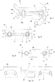
- These and other characteristics of the present invention will become apparent from the following description of some forms of embodiment, given as a non-restrictive example with reference to the attached drawings wherein:
-
fig. 1 is a perspective view of a segment of a curved tube according to the present invention; -
fig. 2 is an exploded view of the segment of tube infig. 1 ; -
fig. 3 is a section view of a first variant of the segment of tube infig. 1 ; -
fig. 4 is a section view of a second variant of the segment of tube infig. 1 ; -
fig. 5 is a section view of a third variant of the segment of tube infig. 1 ; -
fig. 6 is a section view of a fourth variant of the segment of tube infig. 1 ; -
fig. 7 is a perspective view of a forming mold used in the method according to the present invention; -
fig. 8 is a front view of the forming mold infig. 7 in accordance with a first operating condition; -
fig. 9 is a front view of the forming mold infig. 7 in accordance with a second operating condition; -
fig. 10 is a diagram of the apparatus to make a segment of tube in accordance with the present invention. - To facilitate comprehension, the same reference numbers have been used, where possible, to identify identical common elements in the drawings. It is understood that elements and characteristics of one form of embodiment can conveniently be incorporated into other forms of embodiment without further clarifications.
- With reference to
fig. 1 , a tube, hereafter referred to as curvedtubular element 10, to transfer abrasive materials such as concrete or similar, according to the present invention, in this case comprises a curved externaltubular element 11, with a curved extension along a curved axis Z, in this case shaped like the arc of a circle, inside which a curved internaltubular element 12 or anti-wear insert is disposed. - In the forms of embodiment shown in
figs. 1-9 , the curved externaltubular element 11 has an annular cross section. - Forms of embodiment provide that the curved external
tubular element 11 is made of metal material such as carbon steel or light alloys with an aluminum base or other heat deformable materials, with characteristics of great mechanical resistance. - Merely by way of non-restrictive example, the curved external
tubular element 11 is made of aluminum with an internal diameter of about 125 mm, a thickness of about 7 mm, and an average radius of curvature R of about 240 mm. - The curved external
tubular element 11, in the case where it extends in an arc of a circle, develops, along the curved axis Z, for example for an angle comprised between 10° and 180°, in this specific case about 90°. - The curved external
tubular element 11 has aninternal surface 13 and anexternal surface 14. The curved internaltubular element 12 also has aninternal surface 16 and anexternal surface 15. - The curved internal
tubular element 12, which develops for at least part of the curved extension of the curved externaltubular element 11 and has a cross section such as to cover at least part of theinternal surface 13, is inserted into the curved externaltubular element 11 in intimate contact with itsinternal surface 13. - The curved internal
tubular element 12 is made of a very hard material with a resistance to wear greater than that of the material with which the curved externaltubular element 11 is made. - Forms of embodiment of the present invention provide that the curved internal
tubular element 12 is made of ceramic materials, high-resistance steels, cast iron fusions with a high chromium content, chromium carbides or other types of carbides. - In the variant forms of embodiment shown in
figs. 1-3 , the curved internaltubular element 12 has a tubular cross section that extends along said curved axis Z and covers the entireinternal surface 13 of the curved externaltubular element 11. - The curved internal
tubular element 12 has a substantially uniform thickness S in its cross section (figs. 1 and 2 ), even if it is not excluded that, in other forms of embodiment as shown infig. 3 , the curved internaltubular element 12 has a variable thickness S, for example greater in proximity to theextrados 18 and smaller in proximity to theintrados 20. - In other variant forms of embodiment, for example those shown in
figs. 4-6 , it is provided that the curved internaltubular element 12 has a cross section with an annular sector, that is, it covers only part of theinternal surface 13 of the curved externaltubular element 11. In other words, the curved internaltubular element 12 develops circumferentially for an angle α less than 360°, for example about 180° (figs. 4 and 6 ) or about 240° (fig. 5 ). - Indeed, in this case, it is provided that the curved internal
tubular element 12 and theinternal surface 13 of the curved externaltubular element 11 not affected by the curved internaltubular element 12 together define apassage cavity 19 for the abrasive material to be transferred. Instead, in other variants, thepassage cavity 19 is entirely defined by the curved internaltubular element 12 and more precisely by theinternal surface 16 of the curved internal tubular element 12 (figs. 1-3 ). - Forms of embodiment of the present invention provide that the curved internal
tubular element 12 is disposed inside the curved externaltubular element 11, substantially in correspondence to itsextrados 18, that is, in correspondence to the greater radius of curvature of the curved externaltubular element 11. Theextrados 18 of the curved externaltubular element 11 is subjected, during use, to a greater erosive effect and the presence of the curved internaltubular element 12 with properties of resistance to wear in this zone allows to increase the operating life of thecurved tubular segment 10. - In forms of embodiment shown in
figs. 3-5 , it is provided that the curved internaltubular element 12 has a variable thickness S along the circumferential development, assuming a maximum value in proximity to theextrados 18, that is, at the point of maximum wear, and a minimum value as it moves toward theintrados 20 of the curved externaltubular element 11. - The variation of the thickness S of the curved internal
tubular element 12, from theextrados 18 toward theintrados 20, is advantageously gradual and defined so as to obtain a solution of gradual continuity between the curved internaltubular element 12 and theinternal surface 13 of the curved externaltubular element 11 and without irregularities. Possible irregularities present in thepassage cavity 19 could increase the phenomena of wear and reduce the working life of the curvedtubular element 10. - In the variant shown in
fig. 6 , it is provided that the curved externaltubular element 11 comprises two parts, anupper part 11a and alower part 11b, the first disposed toward theextrados 18, and the second disposed toward theintrados 20 and both with the same external radius of the cross section. - The
upper part 11a, disposed toward theextrados 18, has a smaller thickness than thelower part 11b disposed toward theintrados 20, thus identifying anindentation 26 that defines, with theinternal surface 13 of the curved externaltubular element 11, a housing seating 27 in which the curved internaltubular element 12 can be disposed once it is inserted inside the curved externaltubular element 11. - The curved internal
tubular element 12 disposed inside the housing seating 27 is configured to define, together with thelower part 11b of the curved externaltubular element 11, apassage cavity 19, with a circular, continuous and uniform shape, for the passage of the abrasive material. - At the two ends of the curved external
tubular element 11 two flanges 21 (figs 1 and 2 ) can be associated, by welding for example, to connect to other straight or curved tubes. - The
flanges 21 can provide at least a coveringring 22, disposed inside theflanges 21, also made of anti-wear material of the type described previously and disposed in continuity with the curved internaltubular element 12. - Forms of embodiment provide that the
flanges 21 and/or the covering rings 22 are configured to constrain the position of the curved internaltubular element 12 along the curved axis Z. - To make the
curved tubular segment 10 it is provided to use a formingmold 25 conveniently consisting of at least anupper part 23 and at least alower part 24, separable from each other. In the surfaces of themold 25 that come into contact with the curved externaltubular element 11,molding seatings fig. 7 ) are made, worked on the shape and geometry of thecurved tubular segment 10 to be obtained. Themolding seating 28a made in the upper part of themold 23 and themolding seating 28b made in the lower part of themold 24 can be the two parts of the negative of theexternal surface 14 of the curved externaltubular element 11, obtained by sectioning with a through plane through the line of theintrados 20 and the line of theextrados 18. It is not excluded that themold 25 can consist of an equal number or more than twoparts tubular element 11 made in different directions to that explained above. - The apparatus that allows to make the curved tubular segment in accordance with the present invention comprises at least a
heating unit 29, at least amolding unit 31 and at least a coolingunit 30 as shown infig. 10 . - In accordance with variant forms of embodiment, the at least one
heating unit 29 is provided to heat the curved externaltubular element 11 to a value around its temperature of deformation. - In accordance with variant forms of embodiment, the at least one
molding unit 31 consists of at least a formingmold 25 that closes to apply a pressure on theexternal surface 14 of the curved externaltubular element 11 against theexternal surface 15 of the curved internaltubular element 12. - In accordance with variant forms of embodiment, the at least one
cooling unit 30 is provided to achieve the shrinkage effect of the curved externaltubular element 11 by means of cooling and thus obtain a tube without gaps between the curved externaltubular element 11 and the curved internaltubular element 12. - In accordance with variant forms of embodiment, the cooling
unit 30 can be for example a cooling unit using air, or water, or cooling liquid or any other known type. - The method to make the
curved tubular segment 10 provides that the curved externaltubular element 11 and the curved internaltubular element 12 are made separately and of different materials in relation to their specific different functions. - In particular, it is therefore preferable to make the curved external
tubular element 11 of materials with a high mechanical resistance and such as to resist the required working pressures and possible knocks. As far as the curved internaltubular element 12 is concerned, it is advantageous to make it of a material with a high resistance to wear. - Initially, the curved external
tubular element 11 is heated by means of theheating unit 29 to take it to a temperature around its deformation and dilation temperature. The heating can be achieved by means for example of a gas furnace, an induction furnace or any other means suitable to the purpose. - The curved external
tubular element 11, made for example of steel, aluminum or other heat deformable material, is taken by heating to its deformation temperature: to quote an example, construction steel is taken to an approximate temperature about 850°C. - When this suitable temperature has been reached, it is possible to insert the curved internal
tubular element 12 inside the curved externaltubular element 11. - During this step the curved external
tubular element 11 is positioned inside the formingmold 25 which is in the open position, that is, with theupper part 23 separate from thelower part 24 by a measurement at least more than the external diameter of the curved externaltubular element 11 when heated, as visible infig. 7 . At this point, the curved internaltubular element 12 is inserted inside the curved externaltubular element 11, for example in the direction of movement indicated by the arrow M (fig. 7 ). - In accordance with variant forms of embodiment, if the curved internal
tubular element 12 has a cross section with annular sector, that is, it covers only a reduced portion of theinternal surface 13 of the curved externaltubular element 11, disposable completion elements can be provided which re-establish the whole circumference of the curved internaltubular element 12 and which are discharged at the end of the molding cycle. The insertion can be performed manually or in any case with other known positioning systems, for example automated positioning systems. - Since the curved internal
tubular element 12 is inserted when the curved externaltubular element 11 is in a heated condition, in which the constituent material is subjected to a dilation, even of a few millimeters, a play orinterspace 17 is created between theexternal surface 15 of the curved internaltubular element 12 and theinternal surface 13 of the curved externaltubular element 11, which facilitates the insertion operation and correct functioning. - Finally, the
mold 25 is progressively closed in the direction of arrows C (fig. 8 ), for example by means of a press, initially taking theupper part 23 and thelower part 24 into contact with theexternal surface 14 of the curved externaltubular element 11 and subsequently also taking theupper part 23 into contact with thelower part 24 so as to close the forming mold 25 (fig. 9 ). - When closing is completed, the forming
mold 25, exploiting its heated condition, has formed the curved externaltubular element 11 to the desired geometry, that is, theinternal surface 13 of the curved externaltubular element 11 is made to adhere exactly to theexternal surface 15 of the curved internaltubular element 12. - Subsequently, the mold is opened and the curved external
tubular element 11 and the curved internaltubular element 12 are cooled. - The shrinkage of the material as a result of the cooling renders definitive the coupling of the two elements.
- Advantageously, to reduce working times, the step of closing the forming
mold 25 can also take place at the same time as a cooling step carried out by means of the coolingunit 30. - The
curved tubular segment 10 thus obtained is the exact union of the curved externaltubular element 11 and the curved internaltubular element 12, in which theinternal surface 13 of the former and theexternal surface 15 of the latter adhere perfectly, since theinterspace 17 of air that was formed between the two has been eliminated. The curved externaltubular element 11 and the curved internaltubular element 12 are thus solid and collaborate from a mechanical point of view when they are subjected to stresses due to the internal pumping pressure of the concrete. - Moreover the weight of the
curved tubular segment 10 is less than those of the state of the art, since in this way the filling mean has been eliminated. - It is clear that modifications and/or additions of parts may be made to the
curved tubular segment 10 to transport concrete, to the apparatus and corresponding method as described heretofore, without departing from the field and scope of the present invention. - It is also clear that, although the present invention has been described with reference to some specific examples, a person of skill in the art shall certainly be able to achieve many other equivalent forms of
curved tubular segment 10 to transport concrete, apparatus and corresponding method, having the characteristics as set forth in the claims and hence all coming within the field of protection defined thereby.
Claims (11)
- Method for producing a tube or curved segment of tube for transferring abrasive materials such as concrete or suchlike, comprising a curved external tubular element (11) and a curved internal tubular element (12), or anti-wear insert, made of a material having a resistance to wear greater than that of the curved external tubular element (11) and having a cross section such as to cover at least part of the internal surface (13) of the curved external tubular element (11), wherein the method provides to make said curved external tubular element (11) and said curved internal tubular element (12) separately, characterized in that it comprises:- heating said curved external tubular element (11) at least to around its temperature of deformation;- inserting said curved internal tubular element (12) inside said curved external tubular element (11);- closing a mold (25) applying a pressure to an external surface (14) of the curved external tubular element (11) against the external surface (15) of the curved internal tubular element (12) to form the curved external tubular element (11) on the exact geometry of the curved internal tubular element (12), exploiting the heated condition of the curved external tubular element (11);- opening the mold (25) and cooling with consequent shrinkage of the curved external tubular element (11) on the curved internal tubular element (12).
- Method as in claim 1, characterized in that the forming of said curved external tubular element (11) on said curved internal tubular element (12) takes place by means of at least two parts (23, 24) of said mold (25) that progressively close, taking said internal surface (13) of the curved external tubular element (11) to adhere exactly to the external surface (15) of the curved internal tubular element (12).
- Method as in claim 1 or 2, wherein said curved internal tubular element (12) has a cross section such as to cover the entire internal surface (13) of said curved external tubular element (11).
- Method as in claim 1 or 2, wherein said curved internal tubular element (12) has a cross section such as to cover only part of the internal surface (13) of said curved external tubular element (11).
- Method as in claim 4, wherein said curved internal tubular element (12) is disposed in correspondence with the extrados (18) of said curved external tubular element (11).
- Method as in claim 5, wherein said curved internal tubular element (12), together with a lower part (11b) of said curved external tubular element (11), defines a passage cavity (19) with a circular shape.
- Method as in any claim hereinbefore, wherein said curved internal tubular element (12) extends for the same curved extension as said curved external tubular element (11).
- Method as in any claim from 1 to 5, wherein said curved internal tubular element (12) has a circumferentially variable thickness (S), with a maximum value in proximity to the extrados (18), and which diminishes moving toward the intrados (20) of said curved external tubular element (11).
- Method as in any claim hereinbefore, wherein flanges (21) are associated at the ends of the curved tubular segment.
- Method as in claim 9, wherein inside said flanges (21) at least one covering ring (22) is disposed, made of wear resistant material, in continuity with the curved internal tubular element (12).
- Apparatus for producing a curved tubular segment for conveying abrasive materials such as concrete or suchlike, comprising a curved external tubular element (11) and at least a curved internal tubular element (12) housed inside said curved external tubular element (11), having a cross section such as to cover at least part of the internal surface (13) of the curved external tubular element (11) and made of a material having a resistance to wear greater than that of the curved external tubular element (11), characterized in that it comprises:- at least one heating unit (29) to heat the curved external tubular element (11) to a value near its temperature of deformation;- at least one molding unit (31) consisting of at least one forming mold (25) having an internal conformation mating with the geometry of the curved external tubular element (11), comprising at least a mobile part having a closed position in which it applies pressure to the external surface (14) of the curved external tubular element (11) against the external surface (15) of the curved internal tubular element (12);- at least one cooling unit (30) to obtain the shrinkage effect of the curved external tubular element (11).
Applications Claiming Priority (2)
| Application Number | Priority Date | Filing Date | Title |
|---|---|---|---|
| ITMI20150423 | 2015-03-20 | ||
| PCT/IB2015/055557 WO2016151370A1 (en) | 2015-03-20 | 2015-07-22 | Pipe for conveying abrasive materials such as concrete, apparatus and method for producing said pipe |
Publications (2)
| Publication Number | Publication Date |
|---|---|
| EP3271271A1 EP3271271A1 (en) | 2018-01-24 |
| EP3271271B1 true EP3271271B1 (en) | 2018-11-28 |
Family
ID=53267453
Family Applications (1)
| Application Number | Title | Priority Date | Filing Date |
|---|---|---|---|
| EP15759941.6A Active EP3271271B1 (en) | 2015-03-20 | 2015-07-22 | Apparatus and method for producing a pipe for conveying abrasive materials such as concrete |
Country Status (6)
| Country | Link |
|---|---|
| US (1) | US10689211B2 (en) |
| EP (1) | EP3271271B1 (en) |
| CN (1) | CN107580530B (en) |
| ES (1) | ES2713407T3 (en) |
| TR (1) | TR201902637T4 (en) |
| WO (1) | WO2016151370A1 (en) |
Cited By (1)
| Publication number | Priority date | Publication date | Assignee | Title |
|---|---|---|---|---|
| IT201900019544A1 (en) | 2019-10-22 | 2021-04-22 | Valme S R L Unico Socio | TUBULAR ELEMENT FOR THE TRANSFER OF ABRASIVE MATERIALS, IN PARTICULAR CONCRETE, AND PROCEDURE FOR REALIZING IT |
Families Citing this family (4)
| Publication number | Priority date | Publication date | Assignee | Title |
|---|---|---|---|---|
| IT201800003964A1 (en) | 2018-03-26 | 2019-09-26 | Valme S R L Unico Socio | TUBULAR ELEMENT FOR THE TRANSFER OF ABRASIVE MATERIALS, IN PARTICULAR CONCRETE, AND PROCEDURE FOR REALIZING IT |
| IT201800004795A1 (en) | 2018-04-23 | 2019-10-23 | TUBULAR ELEMENT FOR THE TRANSFER OF ABRASIVE MATERIALS, IN PARTICULAR CONCRETE, AND PROCEDURE FOR REALIZING IT | |
| US11485588B2 (en) * | 2020-03-20 | 2022-11-01 | Cnh Industrial America Llc | Wear resistant granular direction altering device |
| CN117020590A (en) * | 2023-10-08 | 2023-11-10 | 核工业西南物理研究院 | Manufacturing method of special pipe with interlayer |
Family Cites Families (28)
| Publication number | Priority date | Publication date | Assignee | Title |
|---|---|---|---|---|
| DE1068206B (en) * | 1955-06-17 | 1959-11-05 | Flexonics Corporation, Maywood, 111. (V. St. A.) | Method for producing a curved pipe fitting |
| US4130300A (en) * | 1978-02-06 | 1978-12-19 | Sheridan Joseph U | Composite abrasion resistant pipe elbow |
| JPS57194832A (en) | 1981-05-25 | 1982-11-30 | Kawasaki Heavy Ind Ltd | Manufacture of double pipe |
| US4461498A (en) * | 1981-12-02 | 1984-07-24 | Victaulic Company Of America | Coupling members for pipeline assemblies |
| US4633913A (en) * | 1983-09-26 | 1987-01-06 | Combustion Engineering, Inc. | Wear-resistant pipe |
| JPS6137318A (en) | 1984-07-30 | 1986-02-22 | Nippon Steel Corp | Production of double pipe |
| JPH0199725A (en) | 1987-10-14 | 1989-04-18 | Dai Ichi High Frequency Co Ltd | Method for bending double layer tube |
| US4865353A (en) * | 1988-02-29 | 1989-09-12 | Osborne Lee R | Abrasion resistant ceramic elbow |
| DE3839582C1 (en) * | 1988-11-24 | 1989-12-28 | Esser-Brieden Gmbh & Co Kg, 4788 Warstein, De | |
| DE4010556A1 (en) * | 1990-04-02 | 1991-10-10 | Esser Brieden Gmbh & Co Kg | DOUBLE-LAYERED TUBE |
| US5170557A (en) * | 1991-05-01 | 1992-12-15 | Benteler Industries, Inc. | Method of forming a double wall, air gap exhaust duct component |
| US5188396A (en) * | 1992-02-26 | 1993-02-23 | Vaughn Calvin | Rebuildable slurry conduit elbow |
| US5301984A (en) * | 1993-01-14 | 1994-04-12 | Farris Sam J | Wear resistant pipe elbow |
| US5363544A (en) * | 1993-05-20 | 1994-11-15 | Benteler Industries, Inc. | Multi-stage dual wall hydroforming |
| CA2150491C (en) * | 1994-06-23 | 2001-10-02 | Robert E. Klemm | Pipe having replaceable wear resistant lined coupler |
| DE19500953C1 (en) * | 1995-01-14 | 1996-07-25 | Esser Werke Gmbh & Co Kg | Arcuate section of tube for fitting in piping for hydraulic or pneumatic conveying of solid materials |
| US6375228B1 (en) * | 1999-03-25 | 2002-04-23 | Construction Forms, Inc. | Coupling units connecting tubular members having a hardened inner wall for carrying mechanically abrasive fluid concrete |
| EP1167858B1 (en) * | 2000-07-01 | 2004-10-06 | Esser -Werke GmbH & Co. KG | Pipe bend for transport of abrasive materials |
| DE10143290B4 (en) * | 2001-09-04 | 2006-02-09 | Esser-Werke Kg | Arcuate double layer pipe |
| DE10324321A1 (en) * | 2003-05-27 | 2004-12-23 | Putzmeister Ag | Delivery pipe for viscous media, in particular, concrete comprises an inner pipe whose material engages with the annular step of the collar element on the inner pipe |
| DE10333678B4 (en) * | 2003-07-24 | 2006-06-08 | Thyssenkrupp Steel Ag | Method for producing a section-wise reinforced tubular support made of metal, in particular for supporting structures in motor vehicles |
| DE502004004881D1 (en) * | 2004-07-03 | 2007-10-18 | Hegler Ralph Peter | Method for the continuous production of a double-walled corrugated pipe with pipe socket, the double-walled corrugated pipe and the device for carrying out the method |
| DE102004038138B4 (en) | 2004-08-05 | 2007-06-06 | Audi Ag | Process for producing a hybrid pipe |
| DE102006001315B3 (en) * | 2006-01-09 | 2007-05-24 | Esser-Werke Gmbh & Co. Kg | Pipe unit assembled of straight and curved segments in particular for transport of concrete, comprises specifically shaped wearing rings |
| DE602006004860D1 (en) * | 2006-06-28 | 2009-03-05 | Italiana Forme Acciaio | Arch element of a metal tube module for transporting concrete or other highly abrasive materials in the liquid state, and method for producing such an element |
| KR100963423B1 (en) | 2009-11-12 | 2010-06-15 | 현대하이스코 주식회사 | Method of manufacturing double-layer water pipe using hydro forming |
| IT1401515B1 (en) | 2010-08-03 | 2013-07-26 | Cifa S P A Unico Socio | PROCEDURE FOR CARRYING OUT A CURVED TUBULAR ELEMENT FOR THE CONVEYANCE OF ABRASIVE MATERIALS SUCH AS CONCRETE, OR SIMILAR, AND CURVED TUBULAR ELEMENT OBTAINED AS FOLLOWS. |
| ITMI20130415A1 (en) | 2013-03-19 | 2014-09-20 | Cifa Spa | PROCEDURE FOR REALIZING A CURVED TUBULAR ELEMENT FOR THE CONVEYANCE OF ABRASIVE MATERIALS AS CONCRETE, OR SIMILAR, AND CURVED TUBULAR ELEMENT OBTAINED |
-
2015
- 2015-07-22 CN CN201580080032.XA patent/CN107580530B/en active Active
- 2015-07-22 US US15/559,920 patent/US10689211B2/en active Active
- 2015-07-22 TR TR2019/02637T patent/TR201902637T4/en unknown
- 2015-07-22 EP EP15759941.6A patent/EP3271271B1/en active Active
- 2015-07-22 WO PCT/IB2015/055557 patent/WO2016151370A1/en not_active Ceased
- 2015-07-22 ES ES15759941T patent/ES2713407T3/en active Active
Non-Patent Citations (1)
| Title |
|---|
| None * |
Cited By (2)
| Publication number | Priority date | Publication date | Assignee | Title |
|---|---|---|---|---|
| IT201900019544A1 (en) | 2019-10-22 | 2021-04-22 | Valme S R L Unico Socio | TUBULAR ELEMENT FOR THE TRANSFER OF ABRASIVE MATERIALS, IN PARTICULAR CONCRETE, AND PROCEDURE FOR REALIZING IT |
| EP3812086A1 (en) | 2019-10-22 | 2021-04-28 | Valme S.r.l. - Unico Socio | Tubular element for the transfer of abrasive materials, in particular concrete, and method to produce it |
Also Published As
| Publication number | Publication date |
|---|---|
| US20180072513A1 (en) | 2018-03-15 |
| ES2713407T3 (en) | 2019-05-21 |
| US10689211B2 (en) | 2020-06-23 |
| TR201902637T4 (en) | 2019-03-21 |
| CN107580530B (en) | 2019-08-27 |
| EP3271271A1 (en) | 2018-01-24 |
| CN107580530A (en) | 2018-01-12 |
| WO2016151370A1 (en) | 2016-09-29 |
Similar Documents
| Publication | Publication Date | Title |
|---|---|---|
| US10689211B2 (en) | Pipe for conveying abrasive materials such as concrete, apparatus and method for producing said pipe | |
| EP2781476A1 (en) | Method to make a curved tubular element to convey abrasive materials such as concrete or suchlike, and curved tubular element thus obtained | |
| EP2601430B1 (en) | Method to make a curved tubular element in order to convey abrasive materials such as concrete or suchlike, and curved tubular element thus obtained | |
| AU2011306789B2 (en) | Method and device for the mutual positioning of pipes with a plurality of geometric measurements | |
| CN107716624B (en) | A method of correction c-type steel-casting | |
| NO160289B (en) | PROCEDURE FOR LINING A BODY, LIKE A VALVE HOUSE. | |
| CN109570296A (en) | A kind of bending method of Stainless Steel U pipe | |
| CN111001960B (en) | Yankee cylinder section pre-processing piece and method for manufacturing Yankee cylinder | |
| EP3538830B1 (en) | Cooling panel coupled to an inner wall of a steel making furnace and associated steel making furnace | |
| US20180180216A1 (en) | Large micro-crystallized glass-lined pipeline and manufacturing method thereof | |
| EP3546090B1 (en) | Method to make a tubular element and tubular element | |
| EP3560630A1 (en) | Tubular element to transfer abrasive materials, in particular concrete, and method to manufacture it | |
| CN104723027A (en) | Method for forging, welding and manufacturing abrasion-resistant metal bent pipes | |
| CN104290178B (en) | A kind of annular furnace liner casting mold and preparation method thereof | |
| CN204387561U (en) | A kind of internal layer is the antifriction metal (AFM) bend pipe structure of semicanal | |
| EP3812086A1 (en) | Tubular element for the transfer of abrasive materials, in particular concrete, and method to produce it | |
| EP2784366A1 (en) | Pipe for transferring abrasive materials and corresponding method of production | |
| RU2730231C1 (en) | Device and method for manufacturing of support part | |
| CN102506238B (en) | Double-layer composite s valve and manufacturing method thereof | |
| CN110125613B (en) | Preparation method of wear-resistant pipeline based on high-carbon high-chromium steel | |
| CN109530629A (en) | Roller covers casting device and preparation method thereof and roller set | |
| EP3892410A4 (en) | METHOD FOR MAKING A HEAT RESISTANT FERRITIC STEEL WELDED JOINT | |
| RU2362941C2 (en) | Pipeline construction method | |
| JPS6138759Y2 (en) | ||
| US104777A (en) | Improvement in molds for car-wheels |
Legal Events
| Date | Code | Title | Description |
|---|---|---|---|
| STAA | Information on the status of an ep patent application or granted ep patent |
Free format text: STATUS: THE INTERNATIONAL PUBLICATION HAS BEEN MADE |
|
| PUAI | Public reference made under article 153(3) epc to a published international application that has entered the european phase |
Free format text: ORIGINAL CODE: 0009012 |
|
| STAA | Information on the status of an ep patent application or granted ep patent |
Free format text: STATUS: REQUEST FOR EXAMINATION WAS MADE |
|
| 17P | Request for examination filed |
Effective date: 20170927 |
|
| AK | Designated contracting states |
Kind code of ref document: A1 Designated state(s): AL AT BE BG CH CY CZ DE DK EE ES FI FR GB GR HR HU IE IS IT LI LT LU LV MC MK MT NL NO PL PT RO RS SE SI SK SM TR |
|
| AX | Request for extension of the european patent |
Extension state: BA ME |
|
| REG | Reference to a national code |
Ref country code: DE Ref legal event code: R079 Ref document number: 602015020488 Country of ref document: DE Free format text: PREVIOUS MAIN CLASS: B65G0053520000 Ipc: B21D0022020000 |
|
| DAV | Request for validation of the european patent (deleted) | ||
| DAX | Request for extension of the european patent (deleted) | ||
| GRAP | Despatch of communication of intention to grant a patent |
Free format text: ORIGINAL CODE: EPIDOSNIGR1 |
|
| STAA | Information on the status of an ep patent application or granted ep patent |
Free format text: STATUS: GRANT OF PATENT IS INTENDED |
|
| RIC1 | Information provided on ipc code assigned before grant |
Ipc: B23P 11/02 20060101ALI20180625BHEP Ipc: B21D 22/02 20060101AFI20180625BHEP Ipc: F16L 57/06 20060101ALI20180625BHEP Ipc: F16L 58/10 20060101ALI20180625BHEP Ipc: F16L 43/00 20060101ALI20180625BHEP Ipc: B21D 39/04 20060101ALI20180625BHEP |
|
| INTG | Intention to grant announced |
Effective date: 20180723 |
|
| GRAS | Grant fee paid |
Free format text: ORIGINAL CODE: EPIDOSNIGR3 |
|
| GRAA | (expected) grant |
Free format text: ORIGINAL CODE: 0009210 |
|
| STAA | Information on the status of an ep patent application or granted ep patent |
Free format text: STATUS: THE PATENT HAS BEEN GRANTED |
|
| AK | Designated contracting states |
Kind code of ref document: B1 Designated state(s): AL AT BE BG CH CY CZ DE DK EE ES FI FR GB GR HR HU IE IS IT LI LT LU LV MC MK MT NL NO PL PT RO RS SE SI SK SM TR |
|
| REG | Reference to a national code |
Ref country code: CH Ref legal event code: EP |
|
| REG | Reference to a national code |
Ref country code: AT Ref legal event code: REF Ref document number: 1069630 Country of ref document: AT Kind code of ref document: T Effective date: 20181215 |
|
| REG | Reference to a national code |
Ref country code: DE Ref legal event code: R096 Ref document number: 602015020488 Country of ref document: DE |
|
| REG | Reference to a national code |
Ref country code: IE Ref legal event code: FG4D |
|
| REG | Reference to a national code |
Ref country code: CH Ref legal event code: NV Representative=s name: MICHELI AND CIE SA, CH |
|
| REG | Reference to a national code |
Ref country code: NL Ref legal event code: MP Effective date: 20181128 |
|
| REG | Reference to a national code |
Ref country code: LT Ref legal event code: MG4D |
|
| PG25 | Lapsed in a contracting state [announced via postgrant information from national office to epo] |
Ref country code: HR Free format text: LAPSE BECAUSE OF FAILURE TO SUBMIT A TRANSLATION OF THE DESCRIPTION OR TO PAY THE FEE WITHIN THE PRESCRIBED TIME-LIMIT Effective date: 20181128 Ref country code: NO Free format text: LAPSE BECAUSE OF FAILURE TO SUBMIT A TRANSLATION OF THE DESCRIPTION OR TO PAY THE FEE WITHIN THE PRESCRIBED TIME-LIMIT Effective date: 20190228 Ref country code: LV Free format text: LAPSE BECAUSE OF FAILURE TO SUBMIT A TRANSLATION OF THE DESCRIPTION OR TO PAY THE FEE WITHIN THE PRESCRIBED TIME-LIMIT Effective date: 20181128 Ref country code: FI Free format text: LAPSE BECAUSE OF FAILURE TO SUBMIT A TRANSLATION OF THE DESCRIPTION OR TO PAY THE FEE WITHIN THE PRESCRIBED TIME-LIMIT Effective date: 20181128 Ref country code: IS Free format text: LAPSE BECAUSE OF FAILURE TO SUBMIT A TRANSLATION OF THE DESCRIPTION OR TO PAY THE FEE WITHIN THE PRESCRIBED TIME-LIMIT Effective date: 20190328 Ref country code: BG Free format text: LAPSE BECAUSE OF FAILURE TO SUBMIT A TRANSLATION OF THE DESCRIPTION OR TO PAY THE FEE WITHIN THE PRESCRIBED TIME-LIMIT Effective date: 20190228 Ref country code: LT Free format text: LAPSE BECAUSE OF FAILURE TO SUBMIT A TRANSLATION OF THE DESCRIPTION OR TO PAY THE FEE WITHIN THE PRESCRIBED TIME-LIMIT Effective date: 20181128 |
|
| REG | Reference to a national code |
Ref country code: ES Ref legal event code: FG2A Ref document number: 2713407 Country of ref document: ES Kind code of ref document: T3 Effective date: 20190521 |
|
| PG25 | Lapsed in a contracting state [announced via postgrant information from national office to epo] |
Ref country code: PT Free format text: LAPSE BECAUSE OF FAILURE TO SUBMIT A TRANSLATION OF THE DESCRIPTION OR TO PAY THE FEE WITHIN THE PRESCRIBED TIME-LIMIT Effective date: 20190328 Ref country code: AL Free format text: LAPSE BECAUSE OF FAILURE TO SUBMIT A TRANSLATION OF THE DESCRIPTION OR TO PAY THE FEE WITHIN THE PRESCRIBED TIME-LIMIT Effective date: 20181128 Ref country code: RS Free format text: LAPSE BECAUSE OF FAILURE TO SUBMIT A TRANSLATION OF THE DESCRIPTION OR TO PAY THE FEE WITHIN THE PRESCRIBED TIME-LIMIT Effective date: 20181128 Ref country code: GR Free format text: LAPSE BECAUSE OF FAILURE TO SUBMIT A TRANSLATION OF THE DESCRIPTION OR TO PAY THE FEE WITHIN THE PRESCRIBED TIME-LIMIT Effective date: 20190301 Ref country code: SE Free format text: LAPSE BECAUSE OF FAILURE TO SUBMIT A TRANSLATION OF THE DESCRIPTION OR TO PAY THE FEE WITHIN THE PRESCRIBED TIME-LIMIT Effective date: 20181128 |
|
| PG25 | Lapsed in a contracting state [announced via postgrant information from national office to epo] |
Ref country code: NL Free format text: LAPSE BECAUSE OF FAILURE TO SUBMIT A TRANSLATION OF THE DESCRIPTION OR TO PAY THE FEE WITHIN THE PRESCRIBED TIME-LIMIT Effective date: 20181128 |
|
| PG25 | Lapsed in a contracting state [announced via postgrant information from national office to epo] |
Ref country code: PL Free format text: LAPSE BECAUSE OF FAILURE TO SUBMIT A TRANSLATION OF THE DESCRIPTION OR TO PAY THE FEE WITHIN THE PRESCRIBED TIME-LIMIT Effective date: 20181128 Ref country code: CZ Free format text: LAPSE BECAUSE OF FAILURE TO SUBMIT A TRANSLATION OF THE DESCRIPTION OR TO PAY THE FEE WITHIN THE PRESCRIBED TIME-LIMIT Effective date: 20181128 Ref country code: DK Free format text: LAPSE BECAUSE OF FAILURE TO SUBMIT A TRANSLATION OF THE DESCRIPTION OR TO PAY THE FEE WITHIN THE PRESCRIBED TIME-LIMIT Effective date: 20181128 |
|
| REG | Reference to a national code |
Ref country code: DE Ref legal event code: R097 Ref document number: 602015020488 Country of ref document: DE |
|
| PG25 | Lapsed in a contracting state [announced via postgrant information from national office to epo] |
Ref country code: SM Free format text: LAPSE BECAUSE OF FAILURE TO SUBMIT A TRANSLATION OF THE DESCRIPTION OR TO PAY THE FEE WITHIN THE PRESCRIBED TIME-LIMIT Effective date: 20181128 Ref country code: EE Free format text: LAPSE BECAUSE OF FAILURE TO SUBMIT A TRANSLATION OF THE DESCRIPTION OR TO PAY THE FEE WITHIN THE PRESCRIBED TIME-LIMIT Effective date: 20181128 Ref country code: SK Free format text: LAPSE BECAUSE OF FAILURE TO SUBMIT A TRANSLATION OF THE DESCRIPTION OR TO PAY THE FEE WITHIN THE PRESCRIBED TIME-LIMIT Effective date: 20181128 Ref country code: RO Free format text: LAPSE BECAUSE OF FAILURE TO SUBMIT A TRANSLATION OF THE DESCRIPTION OR TO PAY THE FEE WITHIN THE PRESCRIBED TIME-LIMIT Effective date: 20181128 |
|
| PLBE | No opposition filed within time limit |
Free format text: ORIGINAL CODE: 0009261 |
|
| STAA | Information on the status of an ep patent application or granted ep patent |
Free format text: STATUS: NO OPPOSITION FILED WITHIN TIME LIMIT |
|
| 26N | No opposition filed |
Effective date: 20190829 |
|
| PG25 | Lapsed in a contracting state [announced via postgrant information from national office to epo] |
Ref country code: MC Free format text: LAPSE BECAUSE OF FAILURE TO SUBMIT A TRANSLATION OF THE DESCRIPTION OR TO PAY THE FEE WITHIN THE PRESCRIBED TIME-LIMIT Effective date: 20181128 |
|
| GBPC | Gb: european patent ceased through non-payment of renewal fee |
Effective date: 20190722 |
|
| REG | Reference to a national code |
Ref country code: BE Ref legal event code: MM Effective date: 20190731 |
|
| PG25 | Lapsed in a contracting state [announced via postgrant information from national office to epo] |
Ref country code: GB Free format text: LAPSE BECAUSE OF NON-PAYMENT OF DUE FEES Effective date: 20190722 |
|
| PG25 | Lapsed in a contracting state [announced via postgrant information from national office to epo] |
Ref country code: BE Free format text: LAPSE BECAUSE OF NON-PAYMENT OF DUE FEES Effective date: 20190731 Ref country code: LU Free format text: LAPSE BECAUSE OF NON-PAYMENT OF DUE FEES Effective date: 20190722 |
|
| PG25 | Lapsed in a contracting state [announced via postgrant information from national office to epo] |
Ref country code: IE Free format text: LAPSE BECAUSE OF NON-PAYMENT OF DUE FEES Effective date: 20190722 |
|
| PG25 | Lapsed in a contracting state [announced via postgrant information from national office to epo] |
Ref country code: CY Free format text: LAPSE BECAUSE OF FAILURE TO SUBMIT A TRANSLATION OF THE DESCRIPTION OR TO PAY THE FEE WITHIN THE PRESCRIBED TIME-LIMIT Effective date: 20181128 |
|
| PG25 | Lapsed in a contracting state [announced via postgrant information from national office to epo] |
Ref country code: MT Free format text: LAPSE BECAUSE OF FAILURE TO SUBMIT A TRANSLATION OF THE DESCRIPTION OR TO PAY THE FEE WITHIN THE PRESCRIBED TIME-LIMIT Effective date: 20181128 Ref country code: HU Free format text: LAPSE BECAUSE OF FAILURE TO SUBMIT A TRANSLATION OF THE DESCRIPTION OR TO PAY THE FEE WITHIN THE PRESCRIBED TIME-LIMIT; INVALID AB INITIO Effective date: 20150722 |
|
| PG25 | Lapsed in a contracting state [announced via postgrant information from national office to epo] |
Ref country code: SI Free format text: LAPSE BECAUSE OF FAILURE TO SUBMIT A TRANSLATION OF THE DESCRIPTION OR TO PAY THE FEE WITHIN THE PRESCRIBED TIME-LIMIT Effective date: 20181128 |
|
| PG25 | Lapsed in a contracting state [announced via postgrant information from national office to epo] |
Ref country code: MK Free format text: LAPSE BECAUSE OF FAILURE TO SUBMIT A TRANSLATION OF THE DESCRIPTION OR TO PAY THE FEE WITHIN THE PRESCRIBED TIME-LIMIT Effective date: 20181128 |
|
| P01 | Opt-out of the competence of the unified patent court (upc) registered |
Effective date: 20230521 |
|
| PGFP | Annual fee paid to national office [announced via postgrant information from national office to epo] |
Ref country code: ES Payment date: 20240807 Year of fee payment: 10 |
|
| PGFP | Annual fee paid to national office [announced via postgrant information from national office to epo] |
Ref country code: DE Payment date: 20250630 Year of fee payment: 11 |
|
| PGFP | Annual fee paid to national office [announced via postgrant information from national office to epo] |
Ref country code: TR Payment date: 20250702 Year of fee payment: 11 Ref country code: IT Payment date: 20250708 Year of fee payment: 11 |
|
| PGFP | Annual fee paid to national office [announced via postgrant information from national office to epo] |
Ref country code: AT Payment date: 20250718 Year of fee payment: 11 Ref country code: FR Payment date: 20250723 Year of fee payment: 11 |
|
| PGFP | Annual fee paid to national office [announced via postgrant information from national office to epo] |
Ref country code: CH Payment date: 20250801 Year of fee payment: 11 |