EP3271066B1 - Structure of integrated photochemical reactor - Google Patents
Structure of integrated photochemical reactor Download PDFInfo
- Publication number
- EP3271066B1 EP3271066B1 EP16719506.4A EP16719506A EP3271066B1 EP 3271066 B1 EP3271066 B1 EP 3271066B1 EP 16719506 A EP16719506 A EP 16719506A EP 3271066 B1 EP3271066 B1 EP 3271066B1
- Authority
- EP
- European Patent Office
- Prior art keywords
- photochemical reactor
- radiation
- photochemical
- reaction tube
- hollow
- Prior art date
- Legal status (The legal status is an assumption and is not a legal conclusion. Google has not performed a legal analysis and makes no representation as to the accuracy of the status listed.)
- Not-in-force
Links
- 238000006243 chemical reaction Methods 0.000 claims description 58
- 230000005855 radiation Effects 0.000 claims description 52
- 239000003153 chemical reaction reagent Substances 0.000 claims description 29
- 239000000463 material Substances 0.000 claims description 25
- 238000006552 photochemical reaction Methods 0.000 claims description 20
- 230000003287 optical effect Effects 0.000 claims description 19
- 230000005284 excitation Effects 0.000 claims description 17
- VYPSYNLAJGMNEJ-UHFFFAOYSA-N Silicium dioxide Chemical compound O=[Si]=O VYPSYNLAJGMNEJ-UHFFFAOYSA-N 0.000 claims description 11
- 239000005350 fused silica glass Substances 0.000 claims description 10
- 230000005670 electromagnetic radiation Effects 0.000 claims description 9
- 238000005086 pumping Methods 0.000 claims description 5
- 230000005672 electromagnetic field Effects 0.000 claims description 3
- 238000002955 isolation Methods 0.000 claims description 3
- 238000000034 method Methods 0.000 description 5
- 229910052751 metal Inorganic materials 0.000 description 4
- 239000002184 metal Substances 0.000 description 4
- 239000012809 cooling fluid Substances 0.000 description 3
- 239000000126 substance Substances 0.000 description 3
- XKRFYHLGVUSROY-UHFFFAOYSA-N Argon Chemical compound [Ar] XKRFYHLGVUSROY-UHFFFAOYSA-N 0.000 description 2
- 230000015572 biosynthetic process Effects 0.000 description 2
- 238000001816 cooling Methods 0.000 description 2
- 230000006866 deterioration Effects 0.000 description 2
- 238000004519 manufacturing process Methods 0.000 description 2
- 229930003316 Vitamin D Natural products 0.000 description 1
- QYSXJUFSXHHAJI-XFEUOLMDSA-N Vitamin D3 Natural products C1(/[C@@H]2CC[C@@H]([C@]2(CCC1)C)[C@H](C)CCCC(C)C)=C/C=C1\C[C@@H](O)CCC1=C QYSXJUFSXHHAJI-XFEUOLMDSA-N 0.000 description 1
- 239000002250 absorbent Substances 0.000 description 1
- 230000002745 absorbent Effects 0.000 description 1
- 230000004913 activation Effects 0.000 description 1
- 229910052786 argon Inorganic materials 0.000 description 1
- 230000008033 biological extinction Effects 0.000 description 1
- 230000003247 decreasing effect Effects 0.000 description 1
- 239000012530 fluid Substances 0.000 description 1
- 239000007789 gas Substances 0.000 description 1
- 239000011521 glass Substances 0.000 description 1
- 230000001939 inductive effect Effects 0.000 description 1
- 239000007788 liquid Substances 0.000 description 1
- QSHDDOUJBYECFT-UHFFFAOYSA-N mercury Chemical compound [Hg] QSHDDOUJBYECFT-UHFFFAOYSA-N 0.000 description 1
- 229910052753 mercury Inorganic materials 0.000 description 1
- 239000007769 metal material Substances 0.000 description 1
- 239000000203 mixture Substances 0.000 description 1
- 230000001699 photocatalysis Effects 0.000 description 1
- 238000010298 pulverizing process Methods 0.000 description 1
- 239000010453 quartz Substances 0.000 description 1
- 230000035484 reaction time Effects 0.000 description 1
- 230000003595 spectral effect Effects 0.000 description 1
- 238000004544 sputter deposition Methods 0.000 description 1
- 230000001954 sterilising effect Effects 0.000 description 1
- 238000004659 sterilization and disinfection Methods 0.000 description 1
- 238000003786 synthesis reaction Methods 0.000 description 1
- 239000012780 transparent material Substances 0.000 description 1
- 235000019166 vitamin D Nutrition 0.000 description 1
- 239000011710 vitamin D Substances 0.000 description 1
- 150000003710 vitamin D derivatives Chemical class 0.000 description 1
- 229940046008 vitamin d Drugs 0.000 description 1
- 238000003466 welding Methods 0.000 description 1
Images



Classifications
-
- B—PERFORMING OPERATIONS; TRANSPORTING
- B01—PHYSICAL OR CHEMICAL PROCESSES OR APPARATUS IN GENERAL
- B01J—CHEMICAL OR PHYSICAL PROCESSES, e.g. CATALYSIS OR COLLOID CHEMISTRY; THEIR RELEVANT APPARATUS
- B01J19/00—Chemical, physical or physico-chemical processes in general; Their relevant apparatus
- B01J19/08—Processes employing the direct application of electric or wave energy, or particle radiation; Apparatus therefor
- B01J19/087—Processes employing the direct application of electric or wave energy, or particle radiation; Apparatus therefor employing electric or magnetic energy
- B01J19/088—Processes employing the direct application of electric or wave energy, or particle radiation; Apparatus therefor employing electric or magnetic energy giving rise to electric discharges
-
- B—PERFORMING OPERATIONS; TRANSPORTING
- B01—PHYSICAL OR CHEMICAL PROCESSES OR APPARATUS IN GENERAL
- B01J—CHEMICAL OR PHYSICAL PROCESSES, e.g. CATALYSIS OR COLLOID CHEMISTRY; THEIR RELEVANT APPARATUS
- B01J19/00—Chemical, physical or physico-chemical processes in general; Their relevant apparatus
- B01J19/08—Processes employing the direct application of electric or wave energy, or particle radiation; Apparatus therefor
- B01J19/12—Processes employing the direct application of electric or wave energy, or particle radiation; Apparatus therefor employing electromagnetic waves
- B01J19/122—Incoherent waves
- B01J19/123—Ultraviolet light
- B01J19/124—Ultraviolet light generated by microwave irradiation
-
- B—PERFORMING OPERATIONS; TRANSPORTING
- B01—PHYSICAL OR CHEMICAL PROCESSES OR APPARATUS IN GENERAL
- B01J—CHEMICAL OR PHYSICAL PROCESSES, e.g. CATALYSIS OR COLLOID CHEMISTRY; THEIR RELEVANT APPARATUS
- B01J19/00—Chemical, physical or physico-chemical processes in general; Their relevant apparatus
- B01J19/08—Processes employing the direct application of electric or wave energy, or particle radiation; Apparatus therefor
- B01J19/12—Processes employing the direct application of electric or wave energy, or particle radiation; Apparatus therefor employing electromagnetic waves
- B01J19/122—Incoherent waves
- B01J19/126—Microwaves
-
- B—PERFORMING OPERATIONS; TRANSPORTING
- B01—PHYSICAL OR CHEMICAL PROCESSES OR APPARATUS IN GENERAL
- B01J—CHEMICAL OR PHYSICAL PROCESSES, e.g. CATALYSIS OR COLLOID CHEMISTRY; THEIR RELEVANT APPARATUS
- B01J19/00—Chemical, physical or physico-chemical processes in general; Their relevant apparatus
- B01J19/08—Processes employing the direct application of electric or wave energy, or particle radiation; Apparatus therefor
- B01J19/12—Processes employing the direct application of electric or wave energy, or particle radiation; Apparatus therefor employing electromagnetic waves
- B01J19/122—Incoherent waves
- B01J19/127—Sunlight; Visible light
-
- B—PERFORMING OPERATIONS; TRANSPORTING
- B01—PHYSICAL OR CHEMICAL PROCESSES OR APPARATUS IN GENERAL
- B01J—CHEMICAL OR PHYSICAL PROCESSES, e.g. CATALYSIS OR COLLOID CHEMISTRY; THEIR RELEVANT APPARATUS
- B01J19/00—Chemical, physical or physico-chemical processes in general; Their relevant apparatus
- B01J19/08—Processes employing the direct application of electric or wave energy, or particle radiation; Apparatus therefor
- B01J19/12—Processes employing the direct application of electric or wave energy, or particle radiation; Apparatus therefor employing electromagnetic waves
- B01J19/122—Incoherent waves
- B01J19/128—Infrared light
-
- B—PERFORMING OPERATIONS; TRANSPORTING
- B01—PHYSICAL OR CHEMICAL PROCESSES OR APPARATUS IN GENERAL
- B01J—CHEMICAL OR PHYSICAL PROCESSES, e.g. CATALYSIS OR COLLOID CHEMISTRY; THEIR RELEVANT APPARATUS
- B01J19/00—Chemical, physical or physico-chemical processes in general; Their relevant apparatus
- B01J19/24—Stationary reactors without moving elements inside
- B01J19/2415—Tubular reactors
- B01J19/2425—Tubular reactors in parallel
-
- B—PERFORMING OPERATIONS; TRANSPORTING
- B01—PHYSICAL OR CHEMICAL PROCESSES OR APPARATUS IN GENERAL
- B01J—CHEMICAL OR PHYSICAL PROCESSES, e.g. CATALYSIS OR COLLOID CHEMISTRY; THEIR RELEVANT APPARATUS
- B01J19/00—Chemical, physical or physico-chemical processes in general; Their relevant apparatus
- B01J19/24—Stationary reactors without moving elements inside
- B01J19/2415—Tubular reactors
- B01J19/243—Tubular reactors spirally, concentrically or zigzag wound
-
- B—PERFORMING OPERATIONS; TRANSPORTING
- B01—PHYSICAL OR CHEMICAL PROCESSES OR APPARATUS IN GENERAL
- B01J—CHEMICAL OR PHYSICAL PROCESSES, e.g. CATALYSIS OR COLLOID CHEMISTRY; THEIR RELEVANT APPARATUS
- B01J19/00—Chemical, physical or physico-chemical processes in general; Their relevant apparatus
- B01J19/24—Stationary reactors without moving elements inside
- B01J19/2415—Tubular reactors
- B01J19/2435—Loop-type reactors
-
- H—ELECTRICITY
- H01—ELECTRIC ELEMENTS
- H01J—ELECTRIC DISCHARGE TUBES OR DISCHARGE LAMPS
- H01J65/00—Lamps without any electrode inside the vessel; Lamps with at least one main electrode outside the vessel
- H01J65/04—Lamps in which a gas filling is excited to luminesce by an external electromagnetic field or by external corpuscular radiation, e.g. for indicating plasma display panels
- H01J65/042—Lamps in which a gas filling is excited to luminesce by an external electromagnetic field or by external corpuscular radiation, e.g. for indicating plasma display panels by an external electromagnetic field
- H01J65/044—Lamps in which a gas filling is excited to luminesce by an external electromagnetic field or by external corpuscular radiation, e.g. for indicating plasma display panels by an external electromagnetic field the field being produced by a separate microwave unit
-
- B—PERFORMING OPERATIONS; TRANSPORTING
- B01—PHYSICAL OR CHEMICAL PROCESSES OR APPARATUS IN GENERAL
- B01J—CHEMICAL OR PHYSICAL PROCESSES, e.g. CATALYSIS OR COLLOID CHEMISTRY; THEIR RELEVANT APPARATUS
- B01J2219/00—Chemical, physical or physico-chemical processes in general; Their relevant apparatus
- B01J2219/08—Processes employing the direct application of electric or wave energy, or particle radiation; Apparatus therefor
- B01J2219/0871—Heating or cooling of the reactor
-
- B—PERFORMING OPERATIONS; TRANSPORTING
- B01—PHYSICAL OR CHEMICAL PROCESSES OR APPARATUS IN GENERAL
- B01J—CHEMICAL OR PHYSICAL PROCESSES, e.g. CATALYSIS OR COLLOID CHEMISTRY; THEIR RELEVANT APPARATUS
- B01J2219/00—Chemical, physical or physico-chemical processes in general; Their relevant apparatus
- B01J2219/08—Processes employing the direct application of electric or wave energy, or particle radiation; Apparatus therefor
- B01J2219/0894—Processes carried out in the presence of a plasma
-
- B—PERFORMING OPERATIONS; TRANSPORTING
- B01—PHYSICAL OR CHEMICAL PROCESSES OR APPARATUS IN GENERAL
- B01J—CHEMICAL OR PHYSICAL PROCESSES, e.g. CATALYSIS OR COLLOID CHEMISTRY; THEIR RELEVANT APPARATUS
- B01J2219/00—Chemical, physical or physico-chemical processes in general; Their relevant apparatus
- B01J2219/08—Processes employing the direct application of electric or wave energy, or particle radiation; Apparatus therefor
- B01J2219/12—Processes employing electromagnetic waves
- B01J2219/1203—Incoherent waves
- B01J2219/1206—Microwaves
- B01J2219/1209—Features relating to the reactor or vessel
- B01J2219/1212—Arrangements of the reactor or the reactors
- B01J2219/1215—Single reactor
-
- B—PERFORMING OPERATIONS; TRANSPORTING
- B01—PHYSICAL OR CHEMICAL PROCESSES OR APPARATUS IN GENERAL
- B01J—CHEMICAL OR PHYSICAL PROCESSES, e.g. CATALYSIS OR COLLOID CHEMISTRY; THEIR RELEVANT APPARATUS
- B01J2219/00—Chemical, physical or physico-chemical processes in general; Their relevant apparatus
- B01J2219/08—Processes employing the direct application of electric or wave energy, or particle radiation; Apparatus therefor
- B01J2219/12—Processes employing electromagnetic waves
- B01J2219/1203—Incoherent waves
- B01J2219/1206—Microwaves
- B01J2219/1209—Features relating to the reactor or vessel
- B01J2219/1221—Features relating to the reactor or vessel the reactor per se
- B01J2219/1224—Form of the reactor
- B01J2219/1227—Reactors comprising tubes with open ends
-
- B—PERFORMING OPERATIONS; TRANSPORTING
- B01—PHYSICAL OR CHEMICAL PROCESSES OR APPARATUS IN GENERAL
- B01J—CHEMICAL OR PHYSICAL PROCESSES, e.g. CATALYSIS OR COLLOID CHEMISTRY; THEIR RELEVANT APPARATUS
- B01J2219/00—Chemical, physical or physico-chemical processes in general; Their relevant apparatus
- B01J2219/08—Processes employing the direct application of electric or wave energy, or particle radiation; Apparatus therefor
- B01J2219/12—Processes employing electromagnetic waves
- B01J2219/1203—Incoherent waves
- B01J2219/1206—Microwaves
- B01J2219/1209—Features relating to the reactor or vessel
- B01J2219/1221—Features relating to the reactor or vessel the reactor per se
- B01J2219/1242—Materials of construction
-
- B—PERFORMING OPERATIONS; TRANSPORTING
- B01—PHYSICAL OR CHEMICAL PROCESSES OR APPARATUS IN GENERAL
- B01J—CHEMICAL OR PHYSICAL PROCESSES, e.g. CATALYSIS OR COLLOID CHEMISTRY; THEIR RELEVANT APPARATUS
- B01J2219/00—Chemical, physical or physico-chemical processes in general; Their relevant apparatus
- B01J2219/08—Processes employing the direct application of electric or wave energy, or particle radiation; Apparatus therefor
- B01J2219/12—Processes employing electromagnetic waves
- B01J2219/1203—Incoherent waves
- B01J2219/1206—Microwaves
- B01J2219/1287—Features relating to the microwave source
- B01J2219/129—Arrangements thereof
- B01J2219/1293—Single source
-
- B—PERFORMING OPERATIONS; TRANSPORTING
- B01—PHYSICAL OR CHEMICAL PROCESSES OR APPARATUS IN GENERAL
- B01J—CHEMICAL OR PHYSICAL PROCESSES, e.g. CATALYSIS OR COLLOID CHEMISTRY; THEIR RELEVANT APPARATUS
- B01J2219/00—Chemical, physical or physico-chemical processes in general; Their relevant apparatus
- B01J2219/08—Processes employing the direct application of electric or wave energy, or particle radiation; Apparatus therefor
- B01J2219/12—Processes employing electromagnetic waves
- B01J2219/1203—Incoherent waves
- B01J2219/1206—Microwaves
- B01J2219/1287—Features relating to the microwave source
- B01J2219/129—Arrangements thereof
- B01J2219/1296—Multiple sources
Definitions
- the present invention relates to the field of photochemical reactions and in particular relates to an innovative photochemical reactor of integrated type.
- the invention relates to a photochemical reactor that does not provide the use of electrodes.
- a photochemical reaction is a chemical reaction that is induced and/or accelerated by the light.
- the energy that is necessary for the development of the chemical reaction is, in fact, provided by the photons that are absorbed by the chemical reagents or different photocatalytic materials, in case they are present.
- photochemical reactions there are the sterilization processes of gases and fluids.
- Other photochemical reactions are those that occur in the synthesis processes of particular substances, for example the vitamin D biosynthesis.
- a first photochemical reactor of prior art comprises a tube made of fused quartz having a coil shape and positioned around a UV lamp.
- This type of photochemical reactor has an important drawback.
- the internal diameter of the tube made of quartz, of which the coil is made cannot be miniaturized for structural reasons. Therefore, if the reagents consist of a solution of highly opaque liquids, that means absorbent to UV, VUV radiations, as almost in all the reactions of interest of the analytical chemistry happens, the radiations are not able to penetrate within the mass of reagents flowing in the tube, consequently decreasing the process efficiency.
- a further solution provides the use of a source of radiations consisting of an arc lamp, i.e. a lamp with metal electrodes arranged into contact with the plasma and between which a discharge is produced.
- a source of radiations consisting of an arc lamp, i.e. a lamp with metal electrodes arranged into contact with the plasma and between which a discharge is produced.
- the main drawbacks of this technical solution are a short life of the lamp, high production costs, the unavoidableness to have the "sputtering", i.e. a cathode pulverization, and the deposit of metal vapours on the internal walls of the lamp.
- a photochemical reactor comprising a reaction chamber that is defined by external walls and contains a plasma.
- the photochemical reactor is equipped, furthermore, with 2 electrodes arranged to produce an electromagnetic field within the reaction chamber. More precisely, the electrodes cause the discharge of the plasma contained within the reaction chamber in such a way to produce a UV light fed by a microwave radiation (MW).
- MW microwave radiation
- an object of the present invention to provide a photochemical reactor that allows to obtain a higher power density on the sample with respect to the solutions of prior art and therefore a higher efficiency of the reaction.
- an object of the present invention to provide a photochemical reactor that allows to considerably reduce the reaction times with respect to the solutions of prior art.
- photochemical reactor comprising:
- the photochemical reactor does not provide the use of electrodes. Therefore, the present invention allows to avoid the drawbacks of the prior art solutions and in particular the deterioration of the electrodes for their direct contact with the plasma.
- the wall of the hollow container body is made of a material transparent to a predetermined electromagnetic radiation.
- reaction container is fixed to said side wall of said hollow container body, for example by welding, in such a way to assure a complete isolation of the excitation chamber from the outside environment.
- the, or each, hollow is a dead hole delimited by a wall that protrudes into said excitation chamber from the side wall of said hollow container body.
- the hollow is a through hole that therefore passes right through the hollow container body.
- the wall of the hollow can coincide with the side wall of the hollow container body, or alternatively protrudes beyond the side wall of the hollow container body for a predetermined length.
- a plurality of hollows is provided, each hollow of said plurality arranged to house, in use, a respective microwave source.
- a plurality of reaction tubes is provided, each reaction tube of said plurality being immersed, in use, in said luminous plasma and arranged to contain respective chemical reagents of a predetermined photochemical reaction.
- the, or each, microwave source is a coaxial dipole antenna.
- the, or each, reaction tube is associated to a shield configured in such a way to selectively blocks said microwaves produced by said, or each, microwave source, but to allow the passage of at least a predetermined electromagnetic radiation of interest emitted by said plasma.
- the electromagnetic radiation of interest is selected from the group consisting of: the ultraviolet radiation, the visible radiation, the infrared radiation, or the vacuum ultraviolet radiation, or any combination thereof.
- the electromagnetic radiation of interest is selected from the group consisting of: the ultraviolet radiation, the visible radiation, the infrared radiation, or the vacuum ultraviolet radiation, or any combination thereof.
- the shield can have a reticular structure.
- la reticular structure of the shield is made of metal.
- reaction tube is part of a double pipe.
- the double pipe comprises:
- the reaction tube is provided as a part of a circuit comprising a pumping device of the reagents, said pumping device arranged to produce a flow of material that passes, in use, through said reaction tube.
- the chemical reagents can flow through the circuit.
- the, or each, reaction tube has a coil shape in such a way to increase the exchange surface through which the optical radiation emitted by the luminous plasma causes the chemical reagents to react photochemically.
- the hollow container body can be made of a transparent fused quartz.
- the, or each, reaction tube is made of a transparent fused quartz.
- the transparent fused quartz since it is transparent to the optical radiation emitted by the plasma, allows, on one hand, the optical radiation to reach the mass of chemical reagents that are present into the reaction tube and, on the other hand, it allows the development of photochemical reactions producing a high energy, in other words, it allows to operate in a large range of temperatures, thanks to the ability to be resistant to very high temperatures.
- a structure of photochemical reactor 1 comprises a hollow container body 10, in particular a bulb, having a side wall 11 made of a chemically inert material, for example glass.
- the material can be transparent to the optical radiation, from the infrared to the vacuum ultraviolet radiation (VUV), and to the microwaves, for example fused quartz.
- the material can be opaque to the electromagnetic radiation, because the fields exciting the plasma does not come from the outside.
- the side wall 11 delimits a closed excitation chamber 12 within which an excitable material 15 is contained, for example, a mixture of argon and mercury.
- the photochemical reactor 1 is provided with at least a hollow 20 made of a material that is transparent to the microwaves, within which, in use, is arranged a source of microwave radiation, preferably a coaxial dipole antenna 25. This is arranged to emit microwaves in such a way to excite the material that is contained within the excitation chamber 12.
- the excitation of the material 15 produces a luminous plasma, which emits an optical radiation having a predetermined wavelength, in particular ultraviolet, visible, or infrared, radiation to which the material in which the hollow container body 10 is made can be transparent, as above disclosed and analogously to what is described in detail in the patent EP1449411 in the name of the same Applicant.
- the photochemical reactor 1 comprises, furthermore, at least a reaction tube 30 within which predetermined chemical reagents are provided. More precisely, the reaction tube 30 is fixed, for example welded, to the side wall 11 of the hollow container body 10, in such a way to assure that the excitation chamber 12 is isolated from the external environment. More in detail, the reaction tube 30 has, in use, at least a portion that is immersed in the luminous plasma.
- reaction tube 30 is made of a material that is transparent to the electromagnetic radiation produced by the luminous plasma, for example transparent fused quartz, the optical radiation emitted by the plasma is free to reach the reagents 35 contained within the reaction tube 30 inducing a predetermined photochemical reaction.
- the present invention allows to arrange the chemical reagents 35, in which the photochemical reaction is induced, directly within the source of optical radiation, i.e. the plasma. Therefore, differently from the solutions of prior art, the radiations penetrate within the reaction tube 30 from every directions and making, therefore, particularly efficient the chemical activation of the reaction. Therefore, with respect to the known solutions, for the same energy that has been absorbed for exciting the material 15, i.e. for the same energy emitted by antenna 25, the sample, i.e. the mass of reagents, is subjected to a higher density of radiation power. This allows to reach a higher yield with respect to the known solutions.
- the mass of chemical reagents 35 is irradiated from every direction and therefore a high uniformity in the treatment of the mass is achieved.
- This latter aspect is very important for the high value of the extinction coefficient of the VUV radiation in many of the materials that are used in the reactors of prior art that obliges to use very small volumes, or to accept a nonuniform treatment.
- the hollow 20 can be substantially a dead hole delimited by a wall 21 protruding into the excitation chamber 12 from the side wall 11 of the hollow container body 10.
- the hollow 20 is a through hole which crosses all the side wall 11 of the container body 10 between an inlet mouth 22 and an outlet mouth 23. More in detail, in the first case, the wall of the hollow 20 coincides with the wall of the hollow container body 10, whilst in the second case, the wall 21 of the hollow 20, for example made of fused quartz, or other transparent material, protrudes beyond the wall 11 of the hollow container body 10 for a predetermined length. In this latter case, the wall 21 of the hollow 20 is provided welded to the side wall 11 of the container body 10, analogously to what has been disclosed for the reaction tube 30. As diagrammatically shown in figures 2B , 4 and 5 , furthermore, the hollow 20 can be a portion of an open tube, i.e. that is not closed neither at the first end nor at the other end.
- the, or each, reaction tube 30 has a coil shape. More precisely, in the case of figure 3A , the coil is arranged at a predetermined distance from the hollow 20, which houses the antenna 25, whilst in the case of figures 3B , the coil develops around the hollow 20. In this latter case all the electromagnetic, optical and microwave radiations, that are present in the plasma act on the reaction with axial rotation symmetry.
- This solution allows, in particular, to increase the exchange surface between the mass of the chemical reagents and the luminous plasma and, thus, the optical radiation of interest.
- reaction tubes 30 for example 2 reaction tubes 30a and 30b, each of which immersed, in use, in the luminous plasma and arranged to contain respective chemical reagents, that are not necessarily different. In this way, it is possible to optimize the available volume increasing the yield of the photochemical reactor 1.
- figure 5 it is, instead, illustrated an embodiment which provides a plurality of hollows 20, in particular a first and a second hollow 20a e 20b, each of which arranged to house, in use, a respective microwave source 25a and 25b.
- a higher radiation power is emitted in the excitable material 15 that is then excited in a more uniform way.
- the reaction tube 30 is associated to a shield 40 configured in such a way to selectively block the microwaves 125 produced by the, or each, microwave source 25, but to allow the passage of the electromagnetic radiation of interest 115, for example the UV radiation and/or the VUV radiation and/or the IR radiation, or the visible radiation.
- the shield 40 can be positioned outside the external wall of the reaction tube 30, as shown in detail in figures 6 and 7 , or within it.
- the shield 40 can have a reticular structure and can be made of a metal material.
- the, or each, reaction tube 30 can be part of a circuit 100 comprising a pumping device 70 of the reagents 35.
- the pumping device 70 is arranged to produce a flow of chemical reagents which, in use, passes through the circuit 100 up to reach the reaction tube 30.
- the reaction tube 30 is part of a double pipe 130 comprising a cooling duct 135 that is coaxially arranged to the reaction tube 30, in particular outside the same, and containing a predetermined cooling fluid ( figure 9 ). In this way, it is possible to control the temperature of the photochemical reaction that occurs in the reaction tube 30, avoiding, in particular, that it can reach too much high temperatures.
Landscapes
- Chemical & Material Sciences (AREA)
- Organic Chemistry (AREA)
- Chemical Kinetics & Catalysis (AREA)
- Physics & Mathematics (AREA)
- Health & Medical Sciences (AREA)
- General Health & Medical Sciences (AREA)
- Toxicology (AREA)
- Electromagnetism (AREA)
- Engineering & Computer Science (AREA)
- Plasma & Fusion (AREA)
- Physical Or Chemical Processes And Apparatus (AREA)
Description
- The present invention relates to the field of photochemical reactions and in particular relates to an innovative photochemical reactor of integrated type.
- In particular, the invention relates to a photochemical reactor that does not provide the use of electrodes.
- As well known, a photochemical reaction is a chemical reaction that is induced and/or accelerated by the light. The energy that is necessary for the development of the chemical reaction is, in fact, provided by the photons that are absorbed by the chemical reagents or different photocatalytic materials, in case they are present.
- Among the more known photochemical reactions there are the sterilization processes of gases and fluids. Other photochemical reactions are those that occur in the synthesis processes of particular substances, for example the vitamin D biosynthesis.
- Many different typologies of photochemical reactors exist within which the photochemical reactions are conducted.
- A first photochemical reactor of prior art comprises a tube made of fused quartz having a coil shape and positioned around a UV lamp. This type of photochemical reactor has an important drawback. In particular, the internal diameter of the tube made of quartz, of which the coil is made, cannot be miniaturized for structural reasons. Therefore, if the reagents consist of a solution of highly opaque liquids, that means absorbent to UV, VUV radiations, as almost in all the reactions of interest of the analytical chemistry happens, the radiations are not able to penetrate within the mass of reagents flowing in the tube, consequently decreasing the process efficiency.
- Another drawback is represented by the position of the coil. This is, in fact, provided outside the source of optical radiation.
- The above disclosed solution causes reflections of the optical radiations at the external surface of the coil. Therefore, in practice, these optical radiations are not involved in the process.
- A further solution provides the use of a source of radiations consisting of an arc lamp, i.e. a lamp with metal electrodes arranged into contact with the plasma and between which a discharge is produced. The main drawbacks of this technical solution are a short life of the lamp, high production costs, the unavoidableness to have the "sputtering", i.e. a cathode pulverization, and the deposit of metal vapours on the internal walls of the lamp. Further drawbacks of this solution derive from the use of high-voltage electrodes, for isolation reasons and safety of use, and for the impossibility of using reactive metal vapours (like, for example, S, K, I, Na, etc.) for the production of spectral emissions of particular interest, because, as well known, these vapours are particularly reactive and provides chemical attacks of the electrodes.
- A solution to the above problem is disclosed in
DE10236717 . In this case a photochemical reactor is provided comprising a reaction chamber that is defined by external walls and contains a plasma. The photochemical reactor is equipped, furthermore, with 2 electrodes arranged to produce an electromagnetic field within the reaction chamber. More precisely, the electrodes cause the discharge of the plasma contained within the reaction chamber in such a way to produce a UV light fed by a microwave radiation (MW). In order to avoid the drawback that has been disclosed with reference to the previous case, and in particular the direct contact of the electrodes with the plasma, which would cause, over time, a deterioration of the electrodes, jeopardizing, and therefore, the effectiveness and the life of the device, in this case the electromagnetic and microwave radiations are introduced within the reaction chamber by means of a waveguide. However, also this solution is not able to satisfactorily overcome the above disclosed drawbacks because of the use of electrodes. - It is then an object of the present invention to provide a photochemical reactor that is able to overcome the above disclosed drawbacks of the prior art solutions.
- It is, in particular, an object of the present invention to provide a photochemical reactor that allows to obtain a higher power density on the sample with respect to the solutions of prior art and therefore a higher efficiency of the reaction.
- It is, furthermore, an object of the present invention to provide a photochemical reactor that allows to considerably reduce the reaction times with respect to the solutions of prior art.
- It is another object of the present invention to provide a photochemical reactor that allows to reduce the amount of unused power of the radiation that is used.
- It is further object of the present invention to provide a photochemical reactor that is able to homogeneously and uniformly treat the mass of reagents.
- It is still another object of the present invention to provide a photochemical reactor that is highly versatile, because it can be used for a large range of reactions, and at the same time that is extremely reliable.
- It is a particular object of the present invention to provide a photochemical reactor that is resistant to very high temperatures.
- It is still another object of the present invention to provide a photochemical reactor that is economically than the photochemical reactors of prior art and that have a much longer average life than the same.
- These and other objects are achieved by the structure of photochemical reactor, according to the invention, comprising:
- a hollow container body having a side wall in un chemically inert material and arranged to contain un excited luminous plasma with electromagnetic fields e defining a closed excitation chamber in which an excitable material is present, in use, in such a way to obtain a discharge of said excited luminous plasma by microwaves irradiation, said hollow container body being provided with:
- at least a hollow which protrudes into said excitation chamber;
- at least a source of microwave radiation positioned, in use, in said hollow, said source of microwave radiation arranged to emit said radiation in such a way to excite said excitable material producing said luminous plasma arranged to emit an optical radiation ad a predetermined wavelength;
- In particular, the photochemical reactor, according to the invention, does not provide the use of electrodes. Therefore, the present invention allows to avoid the drawbacks of the prior art solutions and in particular the deterioration of the electrodes for their direct contact with the plasma.
- Advantageously, the wall of the hollow container body is made of a material transparent to a predetermined electromagnetic radiation.
- In particular, the reaction container is fixed to said side wall of said hollow container body, for example by welding, in such a way to assure a complete isolation of the excitation chamber from the outside environment.
- In particular, the, or each, hollow is a dead hole delimited by a wall that protrudes into said excitation chamber from the side wall of said hollow container body. In a different embodiment of the invention, instead, the hollow is a through hole that therefore passes right through the hollow container body.
- More in detail, the wall of the hollow can coincide with the side wall of the hollow container body, or alternatively protrudes beyond the side wall of the hollow container body for a predetermined length.
- Advantageously, a plurality of hollows is provided, each hollow of said plurality arranged to house, in use, a respective microwave source.
- According to an embodiment of the invention, a plurality of reaction tubes is provided, each reaction tube of said plurality being immersed, in use, in said luminous plasma and arranged to contain respective chemical reagents of a predetermined photochemical reaction.
- Preferably, the, or each, microwave source is a coaxial dipole antenna.
- In particular, the, or each, reaction tube is associated to a shield configured in such a way to selectively blocks said microwaves produced by said, or each, microwave source, but to allow the passage of at least a predetermined electromagnetic radiation of interest emitted by said plasma.
- In particular, the electromagnetic radiation of interest is selected from the group consisting of: the ultraviolet radiation, the visible radiation, the infrared radiation, or the vacuum ultraviolet radiation, or any combination thereof. In this way, it is possible to selectively induce said photochemical reaction in the reagents contained in said, or each, reaction tube.
- For example, the shield can have a reticular structure.
- Preferably, la reticular structure of the shield is made of metal.
- In a different embodiment of the invention, the reaction tube is part of a double pipe.
- More precisely, the double pipe comprises:
- the reaction tube containing said chemical reagents;
- a cooling duct coaxially arranged to the reaction tube and containing a cooling fluid, said cooling fluid arranged to cool the mass of the chemical reagents during the development of the photochemical reaction, in such a way to control the temperature of the photochemical reaction.
- In an embodiment of the invention, the reaction tube is provided as a part of a circuit comprising a pumping device of the reagents, said pumping device arranged to produce a flow of material that passes, in use, through said reaction tube. In this case, the chemical reagents can flow through the circuit.
- In a different embodiment provided by the invention, the, or each, reaction tube has a coil shape in such a way to increase the exchange surface through which the optical radiation emitted by the luminous plasma causes the chemical reagents to react photochemically.
- The hollow container body can be made of a transparent fused quartz.
- Advantageously, the, or each, reaction tube is made of a transparent fused quartz.
- In particular, the transparent fused quartz, since it is transparent to the optical radiation emitted by the plasma, allows, on one hand, the optical radiation to reach the mass of chemical reagents that are present into the reaction tube and, on the other hand, it allows the development of photochemical reactions producing a high energy, in other words, it allows to operate in a large range of temperatures, thanks to the ability to be resistant to very high temperatures.
- The invention will be now shown with the following description of an exemplary embodiment, exemplifying but not limitative, with reference to the attached drawings in which:
-
Figure 1A diagrammatically shows in an elevational side view a first embodiment of a photochemical reactor, according to the invention; -
Figure 2A diagrammatically shows the photochemical reactor offigure 1A in a longitudinal section view; -
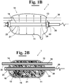
Figures 1B and 2B diagrammatically show in a elevational side view and in a longitudinal section view, respectively, an alternative embodiment of the photochemical reactor offigures 1A and 2A , in which the hollow, which houses the antenna, is a through hole provided in the hollow container body; -
Figures 3A to 6 show in longitudinal section views some alternative embodiments, according to the invention, of the photochemical reactor offigure 2 ; -
Figure 7 shows in detail an enlargement of the embodiment offigure 6 that provides the use of a shield associated to the reaction tube; -
Figures 8 and 9 show further embodiments of the photochemical reactor offigure 1 . - With reference, for example, to
figures 1A and 2A , a structure ofphotochemical reactor 1, according to the invention, comprises ahollow container body 10, in particular a bulb, having aside wall 11 made of a chemically inert material, for example glass. - More precisely, the material can be transparent to the optical radiation, from the infrared to the vacuum ultraviolet radiation (VUV), and to the microwaves, for example fused quartz. Alternatively, the material can be opaque to the electromagnetic radiation, because the fields exciting the plasma does not come from the outside.
- The
side wall 11 delimits aclosed excitation chamber 12 within which anexcitable material 15 is contained, for example, a mixture of argon and mercury. Thephotochemical reactor 1 is provided with at least a hollow 20 made of a material that is transparent to the microwaves, within which, in use, is arranged a source of microwave radiation, preferably acoaxial dipole antenna 25. This is arranged to emit microwaves in such a way to excite the material that is contained within theexcitation chamber 12. The excitation of thematerial 15 produces a luminous plasma, which emits an optical radiation having a predetermined wavelength, in particular ultraviolet, visible, or infrared, radiation to which the material in which thehollow container body 10 is made can be transparent, as above disclosed and analogously to what is described in detail in the patentEP1449411 in the name of the same Applicant. - According to the invention, the
photochemical reactor 1 comprises, furthermore, at least areaction tube 30 within which predetermined chemical reagents are provided. More precisely, thereaction tube 30 is fixed, for example welded, to theside wall 11 of thehollow container body 10, in such a way to assure that theexcitation chamber 12 is isolated from the external environment. More in detail, thereaction tube 30 has, in use, at least a portion that is immersed in the luminous plasma. - Since the
reaction tube 30 is made of a material that is transparent to the electromagnetic radiation produced by the luminous plasma, for example transparent fused quartz, the optical radiation emitted by the plasma is free to reach thereagents 35 contained within thereaction tube 30 inducing a predetermined photochemical reaction. - In particular, the present invention allows to arrange the
chemical reagents 35, in which the photochemical reaction is induced, directly within the source of optical radiation, i.e. the plasma. Therefore, differently from the solutions of prior art, the radiations penetrate within thereaction tube 30 from every directions and making, therefore, particularly efficient the chemical activation of the reaction. Therefore, with respect to the known solutions, for the same energy that has been absorbed for exciting the material 15, i.e. for the same energy emitted byantenna 25, the sample, i.e. the mass of reagents, is subjected to a higher density of radiation power. This allows to reach a higher yield with respect to the known solutions. - Furthermore, the mass of
chemical reagents 35 is irradiated from every direction and therefore a high uniformity in the treatment of the mass is achieved. This latter aspect is very important for the high value of the extinction coefficient of the VUV radiation in many of the materials that are used in the reactors of prior art that obliges to use very small volumes, or to accept a nonuniform treatment. - The possibility to be able to make both the
reaction tube 30 and thehollow body 10 in transparent fused quartz allows to use thereactor 1 also for photochemical reactions that develops at high temperatures thus increasing the range of photochemical reactions that can be conducted using thereactor 1 according to the invention. This constructive solution allows, furthermore, to reduce as desired the thickness of the wall of thereaction tube 30 and therefore to further optimize the process. - As shown, for example, in
figures 1A and 2A , the hollow 20 can be substantially a dead hole delimited by awall 21 protruding into theexcitation chamber 12 from theside wall 11 of thehollow container body 10. - In a different embodiment of the invention shown in
figures 1B and 2B , instead, the hollow 20 is a through hole which crosses all theside wall 11 of thecontainer body 10 between aninlet mouth 22 and anoutlet mouth 23. More in detail, in the first case, the wall of the hollow 20 coincides with the wall of thehollow container body 10, whilst in the second case, thewall 21 of the hollow 20, for example made of fused quartz, or other transparent material, protrudes beyond thewall 11 of thehollow container body 10 for a predetermined length. In this latter case, thewall 21 of the hollow 20 is provided welded to theside wall 11 of thecontainer body 10, analogously to what has been disclosed for thereaction tube 30. As diagrammatically shown infigures 2B ,4 and5 , furthermore, the hollow 20 can be a portion of an open tube, i.e. that is not closed neither at the first end nor at the other end. - In the embodiments of
figures 3A and 3B , the, or each,reaction tube 30 has a coil shape. More precisely, in the case offigure 3A , the coil is arranged at a predetermined distance from the hollow 20, which houses theantenna 25, whilst in the case offigures 3B , the coil develops around the hollow 20. In this latter case all the electromagnetic, optical and microwave radiations, that are present in the plasma act on the reaction with axial rotation symmetry. - This solution allows, in particular, to increase the exchange surface between the mass of the chemical reagents and the luminous plasma and, thus, the optical radiation of interest.
- In the different embodiment of the invention of
figure 4 , instead, a plurality ofreaction tubes 30 is provided, for example 2reaction tubes photochemical reactor 1. - In
figure 5 , it is, instead, illustrated an embodiment which provides a plurality ofhollows 20, in particular a first and a secondhollow 20a e 20b, each of which arranged to house, in use, arespective microwave source microwave antennas 25, a higher radiation power is emitted in theexcitable material 15 that is then excited in a more uniform way. - It is to be noted that, even though in the example of
figure 5 is shown the case in which a hollow, and precisely the first hollow 20a, is a dead hole, whilst another hollow, and precisely the second hollow 20b, is a through hole passing through thecontainer body 10 between aninlet mouth 22 and anoutlet mouth 23, it is also provided the possibility, not shown in the figure for reasons of simplicity, that all thehollows 20 can be dead holes, or through holes, or that a part of the hollows can be dead holes and another part can be through holes. - In the exemplary embodiment shown in
figures 6 and 7 , thereaction tube 30 is associated to ashield 40 configured in such a way to selectively block themicrowaves 125 produced by the, or each,microwave source 25, but to allow the passage of the electromagnetic radiation ofinterest 115, for example the UV radiation and/or the VUV radiation and/or the IR radiation, or the visible radiation. More in detail, theshield 40 can be positioned outside the external wall of thereaction tube 30, as shown in detail infigures 6 and 7 , or within it. - In this way, it is, therefore, possible to selectively induce a photochemical reaction in the
reagents 35 that are contained within thereaction tube 30. For example, theshield 40 can have a reticular structure and can be made of a metal material. - In the further embodiment of
figure 8 , the, or each,reaction tube 30 can be part of acircuit 100 comprising apumping device 70 of thereagents 35. In particular, thepumping device 70 is arranged to produce a flow of chemical reagents which, in use, passes through thecircuit 100 up to reach thereaction tube 30. - In a different embodiment of the invention, the
reaction tube 30 is part of adouble pipe 130 comprising a coolingduct 135 that is coaxially arranged to thereaction tube 30, in particular outside the same, and containing a predetermined cooling fluid (figure 9 ). In this way, it is possible to control the temperature of the photochemical reaction that occurs in thereaction tube 30, avoiding, in particular, that it can reach too much high temperatures.
Claims (15)
- Structure of photochemical reactor (1) comprising:- a hollow container body (10) having a side wall (11) in a chemically inert material and arranged to contain an excited luminous plasma con electromagnetic fields and defining a closed excitation chamber (12) in which an excitable material (15) is present in such a way to obtain a discharge of said excited luminous plasma by microwave irradiation, said hollow container body (10) being provided with:- at least a hollow (20) which protrudes into said excitation chamber (12);- at least a source of microwave radiation positioned in said hollow (20), said source of microwave radiation (25) arranged to emit said radiation, in such a way to excite said excitable material (15) producing said luminous plasma arranged to emit an optical radiation having a predetermined wavelength;said photochemical reactor (1) characterised in that said hollow (20) is delimited by a wall (21) which protrudes into said excitation chamber (12), whereby said source of microwave radiation (25) is not into contact with said plasma and in that a reaction tube (30) is, furthermore, provided arranged to pass through said excitation chamber (12), in such a way to be immersed in said luminous plasma, said reaction tube (30) arranged to contain predetermined chemical reagents (35) and being made of a material transparent to said predetermined optical radiation emitted by said luminous plasma, in such a way that said optical radiation is arranged to hit said chemical reagents (35) in such a way to induce a predetermined photochemical reaction.
- Structure of photochemical reactor (1), according to claim 1, wherein said reaction container (30) is fixed to said side wall (11) of said hollow container body (10), in such a way to assure a complete isolation of said excitation chamber (12) from the outside environment.
- Structure of photochemical reactor (1), according to claim 1, wherein said, or each, hollow (20) is selected from the group consisting of:- a dead hole delimited by a wall (21) which protrudes into said excitation chamber (12) from said side wall (11) of said hollow container body (10).- a through hole arranged to pass through said side wall of said hollow container body (10) between an inlet mouth (22) and an outlet mouth (23).
- Structure of photochemical reactor (1), according to any of the previous claims, wherein a plurality of hollows (20) is provided, each hollow (20) of said plurality being arranged to house, in use, a respective microwave source (25).
- Structure of photochemical reactor (1), according to any of the previous claims, wherein a plurality of reaction tubes (30) is provided, each reaction tube (30) of said plurality being immersed, in use, in said luminous plasma and arranged to contain respective chemical reagents of a predetermined photochemical reaction.
- Structure of photochemical reactor (1), according to any of the previous claims, wherein said, or each, microwave source (25) is a coaxial dipole antenna.
- Structure of photochemical reactor (1), according to any of the previous claims, wherein said, or each, reaction tube (30) is associated to a shield (40) configured in such a way to selectively block said microwaves produced by said, or each, microwave source (25), but to allow the passage of at least a predetermined electromagnetic radiation of interest emitted by said plasma.
- Structure of photochemical reactor (1), according to claim 7, wherein said electromagnetic radiation of interest is selected from the group consisting of:- ultraviolet radiation;- visible radiation;- infrared radiation;- vacuum ultraviolet radiation;- or a combination thereof.
- Structure of photochemical reactor (1), according to claim 7, wherein said shield (40) has a reticular structure.
- Structure of photochemical reactor (1), according to claim 1, wherein said reaction tube (30) is part of a double pipe (130)
- Structure of photochemical reactor (1), according to any of the previous claims, wherein said, or each, reaction tube (30) is provided as a part of a circuit (100) comprising a pumping device (70) arranged to produce a flow of material comprising said reagents (35) which is configured to pass through said, or each reaction tube (35).
- Structure of photochemical reactor (1), according to any of the previous claims, wherein said, or each, reaction tube (30) has a coil shape, in such a way to increase the exchange surface through which said optical radiation emitted by said luminous plasma induce said photochemical reaction in said chemical reagents (35).
- Structure of photochemical reactor (1), according to any of the previous claims, wherein said side wall (11) of said hollow container body (10) is made of a material that is transparent to a predetermined electromagnetic radiation.
- Structure of photochemical reactor (1), according to any of the previous claims, wherein said hollow container body (10) is made of transparent fused quartz.
- Structure of photochemical reactor (1), according to any of the previous claims, wherein, said, or each, reaction tube (30) is made of transparent fused quartz.
Applications Claiming Priority (2)
| Application Number | Priority Date | Filing Date | Title |
|---|---|---|---|
| ITPI20150022 | 2015-03-20 | ||
| PCT/IB2016/051502 WO2016151439A1 (en) | 2015-03-20 | 2016-03-17 | Structure of integrated photochemical reactor |
Publications (2)
| Publication Number | Publication Date |
|---|---|
| EP3271066A1 EP3271066A1 (en) | 2018-01-24 |
| EP3271066B1 true EP3271066B1 (en) | 2019-02-27 |
Family
ID=52781199
Family Applications (1)
| Application Number | Title | Priority Date | Filing Date |
|---|---|---|---|
| EP16719506.4A Not-in-force EP3271066B1 (en) | 2015-03-20 | 2016-03-17 | Structure of integrated photochemical reactor |
Country Status (3)
| Country | Link |
|---|---|
| US (1) | US20180093247A1 (en) |
| EP (1) | EP3271066B1 (en) |
| WO (1) | WO2016151439A1 (en) |
Families Citing this family (2)
| Publication number | Priority date | Publication date | Assignee | Title |
|---|---|---|---|---|
| CN114432988A (en) * | 2020-11-02 | 2022-05-06 | 中国石油化工股份有限公司 | Continuous microwave reaction device and application thereof |
| US12325651B2 (en) * | 2023-01-23 | 2025-06-10 | United Arab Emirates University | Biodesalination using microbial attached growth cultivation |
Family Cites Families (3)
| Publication number | Priority date | Publication date | Assignee | Title |
|---|---|---|---|---|
| PT1200985E (en) * | 1999-07-29 | 2012-07-17 | Sev Trent Water Purification Inc | Uv light source |
| DE10236717B4 (en) * | 2001-08-07 | 2006-04-20 | Gudernatsch, Willi, Dr.-Ing. | Apparatus for carrying out photoreactive processes in a fluid |
| ITPI20010078A1 (en) * | 2001-11-29 | 2003-05-29 | Cnr Consiglio Naz Delle Rice R | METHOD FOR PRODUCTION WITH A LAMP WITHOUT ELECTRODES OF A UV RADIATION. VISIBLE OR IR AND LAMP THAT IMPLEMENTS THIS METHOD |
-
2016
- 2016-03-17 WO PCT/IB2016/051502 patent/WO2016151439A1/en not_active Ceased
- 2016-03-17 EP EP16719506.4A patent/EP3271066B1/en not_active Not-in-force
- 2016-03-17 US US15/559,907 patent/US20180093247A1/en not_active Abandoned
Non-Patent Citations (1)
| Title |
|---|
| None * |
Also Published As
| Publication number | Publication date |
|---|---|
| EP3271066A1 (en) | 2018-01-24 |
| WO2016151439A1 (en) | 2016-09-29 |
| US20180093247A1 (en) | 2018-04-05 |
Similar Documents
| Publication | Publication Date | Title |
|---|---|---|
| CN104780945B (en) | Compact systems with high uniformity radiation field | |
| EP2598444B1 (en) | Device for subjecting a fluid to a disinfecting treatment by exposing the fluid to ultraviolet light | |
| US8834789B2 (en) | Fluid treatment system comprising radiation source module and cooling means | |
| US7863590B2 (en) | UV irradiator | |
| JP2011145299A5 (en) | ||
| US6348669B1 (en) | RF/microwave energized plasma light source | |
| US20180093247A1 (en) | Structure of integrated photochemical reactor | |
| EP1449411B1 (en) | Method for the production of a visible; uv or ir radiation with a lamp without electrodes; and lamp that carries out this method | |
| EP2203930B1 (en) | Microwave lamp with solid dielectric waveguide | |
| CN101443280A (en) | Device for treating fluids, especially water sterilization, comprising an electrode-less gas discharge lamp | |
| JP2003159314A (en) | UV sterilizer | |
| CN102522307B (en) | Radio-frequency discharge ionization device enhanced by using photoelectric effect | |
| JP2001307507A (en) | Electrodeless low pressure discharge lamp | |
| JPS61208743A (en) | Ultraviolet treatment device | |
| RU2006140684A (en) | PLASMA BURNER OF A NEW TYPE AND ITS APPLICATION IN METHODS OF TRANSFORMATION OF SUBSTANCE | |
| JP2000334295A (en) | Photo-reactor with built-in photo-reaction tube | |
| US9718705B2 (en) | UV light source having combined ionization and formation of excimers | |
| RU2280617C1 (en) | Apparatus for combined bactericidal treatment (variations) | |
| JP5049004B2 (en) | Ultraviolet light source and chemical reaction accelerator | |
| KR100832398B1 (en) | Electrodeless zirconium UV lamp and liquid sterilizer | |
| JP2009226370A (en) | Fluid treatment apparatus | |
| US12187626B2 (en) | Apparatus and method for purifying water | |
| Pereira et al. | Microwave-assisted ultraviolet digestion | |
| WO2004036619A1 (en) | Ultraviolet irradiation device | |
| JP6452244B2 (en) | Microwave excitation electrodeless lamp and aqueous solution treatment system using the same |
Legal Events
| Date | Code | Title | Description |
|---|---|---|---|
| STAA | Information on the status of an ep patent application or granted ep patent |
Free format text: STATUS: THE INTERNATIONAL PUBLICATION HAS BEEN MADE |
|
| PUAI | Public reference made under article 153(3) epc to a published international application that has entered the european phase |
Free format text: ORIGINAL CODE: 0009012 |
|
| STAA | Information on the status of an ep patent application or granted ep patent |
Free format text: STATUS: REQUEST FOR EXAMINATION WAS MADE |
|
| 17P | Request for examination filed |
Effective date: 20171010 |
|
| AK | Designated contracting states |
Kind code of ref document: A1 Designated state(s): AL AT BE BG CH CY CZ DE DK EE ES FI FR GB GR HR HU IE IS IT LI LT LU LV MC MK MT NL NO PL PT RO RS SE SI SK SM TR |
|
| AX | Request for extension of the european patent |
Extension state: BA ME |
|
| RIN1 | Information on inventor provided before grant (corrected) |
Inventor name: LONGO, IGINIO Inventor name: FERRARI, CARLO |
|
| DAV | Request for validation of the european patent (deleted) | ||
| DAX | Request for extension of the european patent (deleted) | ||
| GRAP | Despatch of communication of intention to grant a patent |
Free format text: ORIGINAL CODE: EPIDOSNIGR1 |
|
| STAA | Information on the status of an ep patent application or granted ep patent |
Free format text: STATUS: GRANT OF PATENT IS INTENDED |
|
| INTG | Intention to grant announced |
Effective date: 20180910 |
|
| GRAS | Grant fee paid |
Free format text: ORIGINAL CODE: EPIDOSNIGR3 |
|
| GRAA | (expected) grant |
Free format text: ORIGINAL CODE: 0009210 |
|
| STAA | Information on the status of an ep patent application or granted ep patent |
Free format text: STATUS: THE PATENT HAS BEEN GRANTED |
|
| AK | Designated contracting states |
Kind code of ref document: B1 Designated state(s): AL AT BE BG CH CY CZ DE DK EE ES FI FR GB GR HR HU IE IS IT LI LT LU LV MC MK MT NL NO PL PT RO RS SE SI SK SM TR |
|
| REG | Reference to a national code |
Ref country code: GB Ref legal event code: FG4D |
|
| REG | Reference to a national code |
Ref country code: CH Ref legal event code: EP |
|
| REG | Reference to a national code |
Ref country code: AT Ref legal event code: REF Ref document number: 1100528 Country of ref document: AT Kind code of ref document: T Effective date: 20190315 |
|
| REG | Reference to a national code |
Ref country code: IE Ref legal event code: FG4D |
|
| REG | Reference to a national code |
Ref country code: DE Ref legal event code: R096 Ref document number: 602016010414 Country of ref document: DE |
|
| REG | Reference to a national code |
Ref country code: NL Ref legal event code: MP Effective date: 20190227 |
|
| REG | Reference to a national code |
Ref country code: LT Ref legal event code: MG4D |
|
| PG25 | Lapsed in a contracting state [announced via postgrant information from national office to epo] |
Ref country code: NL Free format text: LAPSE BECAUSE OF FAILURE TO SUBMIT A TRANSLATION OF THE DESCRIPTION OR TO PAY THE FEE WITHIN THE PRESCRIBED TIME-LIMIT Effective date: 20190227 Ref country code: LT Free format text: LAPSE BECAUSE OF FAILURE TO SUBMIT A TRANSLATION OF THE DESCRIPTION OR TO PAY THE FEE WITHIN THE PRESCRIBED TIME-LIMIT Effective date: 20190227 Ref country code: NO Free format text: LAPSE BECAUSE OF FAILURE TO SUBMIT A TRANSLATION OF THE DESCRIPTION OR TO PAY THE FEE WITHIN THE PRESCRIBED TIME-LIMIT Effective date: 20190527 Ref country code: FI Free format text: LAPSE BECAUSE OF FAILURE TO SUBMIT A TRANSLATION OF THE DESCRIPTION OR TO PAY THE FEE WITHIN THE PRESCRIBED TIME-LIMIT Effective date: 20190227 Ref country code: SE Free format text: LAPSE BECAUSE OF FAILURE TO SUBMIT A TRANSLATION OF THE DESCRIPTION OR TO PAY THE FEE WITHIN THE PRESCRIBED TIME-LIMIT Effective date: 20190227 Ref country code: PT Free format text: LAPSE BECAUSE OF FAILURE TO SUBMIT A TRANSLATION OF THE DESCRIPTION OR TO PAY THE FEE WITHIN THE PRESCRIBED TIME-LIMIT Effective date: 20190627 |
|
| PG25 | Lapsed in a contracting state [announced via postgrant information from national office to epo] |
Ref country code: BG Free format text: LAPSE BECAUSE OF FAILURE TO SUBMIT A TRANSLATION OF THE DESCRIPTION OR TO PAY THE FEE WITHIN THE PRESCRIBED TIME-LIMIT Effective date: 20190527 Ref country code: GR Free format text: LAPSE BECAUSE OF FAILURE TO SUBMIT A TRANSLATION OF THE DESCRIPTION OR TO PAY THE FEE WITHIN THE PRESCRIBED TIME-LIMIT Effective date: 20190528 Ref country code: IS Free format text: LAPSE BECAUSE OF FAILURE TO SUBMIT A TRANSLATION OF THE DESCRIPTION OR TO PAY THE FEE WITHIN THE PRESCRIBED TIME-LIMIT Effective date: 20190627 Ref country code: LV Free format text: LAPSE BECAUSE OF FAILURE TO SUBMIT A TRANSLATION OF THE DESCRIPTION OR TO PAY THE FEE WITHIN THE PRESCRIBED TIME-LIMIT Effective date: 20190227 Ref country code: HR Free format text: LAPSE BECAUSE OF FAILURE TO SUBMIT A TRANSLATION OF THE DESCRIPTION OR TO PAY THE FEE WITHIN THE PRESCRIBED TIME-LIMIT Effective date: 20190227 Ref country code: RS Free format text: LAPSE BECAUSE OF FAILURE TO SUBMIT A TRANSLATION OF THE DESCRIPTION OR TO PAY THE FEE WITHIN THE PRESCRIBED TIME-LIMIT Effective date: 20190227 |
|
| REG | Reference to a national code |
Ref country code: AT Ref legal event code: MK05 Ref document number: 1100528 Country of ref document: AT Kind code of ref document: T Effective date: 20190227 |
|
| PG25 | Lapsed in a contracting state [announced via postgrant information from national office to epo] |
Ref country code: CZ Free format text: LAPSE BECAUSE OF FAILURE TO SUBMIT A TRANSLATION OF THE DESCRIPTION OR TO PAY THE FEE WITHIN THE PRESCRIBED TIME-LIMIT Effective date: 20190227 Ref country code: AL Free format text: LAPSE BECAUSE OF FAILURE TO SUBMIT A TRANSLATION OF THE DESCRIPTION OR TO PAY THE FEE WITHIN THE PRESCRIBED TIME-LIMIT Effective date: 20190227 Ref country code: RO Free format text: LAPSE BECAUSE OF FAILURE TO SUBMIT A TRANSLATION OF THE DESCRIPTION OR TO PAY THE FEE WITHIN THE PRESCRIBED TIME-LIMIT Effective date: 20190227 Ref country code: ES Free format text: LAPSE BECAUSE OF FAILURE TO SUBMIT A TRANSLATION OF THE DESCRIPTION OR TO PAY THE FEE WITHIN THE PRESCRIBED TIME-LIMIT Effective date: 20190227 Ref country code: EE Free format text: LAPSE BECAUSE OF FAILURE TO SUBMIT A TRANSLATION OF THE DESCRIPTION OR TO PAY THE FEE WITHIN THE PRESCRIBED TIME-LIMIT Effective date: 20190227 Ref country code: SK Free format text: LAPSE BECAUSE OF FAILURE TO SUBMIT A TRANSLATION OF THE DESCRIPTION OR TO PAY THE FEE WITHIN THE PRESCRIBED TIME-LIMIT Effective date: 20190227 Ref country code: DK Free format text: LAPSE BECAUSE OF FAILURE TO SUBMIT A TRANSLATION OF THE DESCRIPTION OR TO PAY THE FEE WITHIN THE PRESCRIBED TIME-LIMIT Effective date: 20190227 |
|
| REG | Reference to a national code |
Ref country code: CH Ref legal event code: PL |
|
| REG | Reference to a national code |
Ref country code: DE Ref legal event code: R097 Ref document number: 602016010414 Country of ref document: DE |
|
| PG25 | Lapsed in a contracting state [announced via postgrant information from national office to epo] |
Ref country code: PL Free format text: LAPSE BECAUSE OF FAILURE TO SUBMIT A TRANSLATION OF THE DESCRIPTION OR TO PAY THE FEE WITHIN THE PRESCRIBED TIME-LIMIT Effective date: 20190227 Ref country code: SM Free format text: LAPSE BECAUSE OF FAILURE TO SUBMIT A TRANSLATION OF THE DESCRIPTION OR TO PAY THE FEE WITHIN THE PRESCRIBED TIME-LIMIT Effective date: 20190227 Ref country code: LU Free format text: LAPSE BECAUSE OF NON-PAYMENT OF DUE FEES Effective date: 20190317 |
|
| REG | Reference to a national code |
Ref country code: BE Ref legal event code: MM Effective date: 20190331 |
|
| PG25 | Lapsed in a contracting state [announced via postgrant information from national office to epo] |
Ref country code: MC Free format text: LAPSE BECAUSE OF FAILURE TO SUBMIT A TRANSLATION OF THE DESCRIPTION OR TO PAY THE FEE WITHIN THE PRESCRIBED TIME-LIMIT Effective date: 20190227 Ref country code: AT Free format text: LAPSE BECAUSE OF FAILURE TO SUBMIT A TRANSLATION OF THE DESCRIPTION OR TO PAY THE FEE WITHIN THE PRESCRIBED TIME-LIMIT Effective date: 20190227 |
|
| PLBE | No opposition filed within time limit |
Free format text: ORIGINAL CODE: 0009261 |
|
| STAA | Information on the status of an ep patent application or granted ep patent |
Free format text: STATUS: NO OPPOSITION FILED WITHIN TIME LIMIT |
|
| PG25 | Lapsed in a contracting state [announced via postgrant information from national office to epo] |
Ref country code: LI Free format text: LAPSE BECAUSE OF NON-PAYMENT OF DUE FEES Effective date: 20190331 Ref country code: IE Free format text: LAPSE BECAUSE OF NON-PAYMENT OF DUE FEES Effective date: 20190317 Ref country code: CH Free format text: LAPSE BECAUSE OF NON-PAYMENT OF DUE FEES Effective date: 20190331 |
|
| 26N | No opposition filed |
Effective date: 20191128 |
|
| PG25 | Lapsed in a contracting state [announced via postgrant information from national office to epo] |
Ref country code: SI Free format text: LAPSE BECAUSE OF FAILURE TO SUBMIT A TRANSLATION OF THE DESCRIPTION OR TO PAY THE FEE WITHIN THE PRESCRIBED TIME-LIMIT Effective date: 20190227 Ref country code: BE Free format text: LAPSE BECAUSE OF NON-PAYMENT OF DUE FEES Effective date: 20190331 |
|
| PG25 | Lapsed in a contracting state [announced via postgrant information from national office to epo] |
Ref country code: TR Free format text: LAPSE BECAUSE OF FAILURE TO SUBMIT A TRANSLATION OF THE DESCRIPTION OR TO PAY THE FEE WITHIN THE PRESCRIBED TIME-LIMIT Effective date: 20190227 |
|
| PG25 | Lapsed in a contracting state [announced via postgrant information from national office to epo] |
Ref country code: MT Free format text: LAPSE BECAUSE OF NON-PAYMENT OF DUE FEES Effective date: 20190317 |
|
| PG25 | Lapsed in a contracting state [announced via postgrant information from national office to epo] |
Ref country code: CY Free format text: LAPSE BECAUSE OF FAILURE TO SUBMIT A TRANSLATION OF THE DESCRIPTION OR TO PAY THE FEE WITHIN THE PRESCRIBED TIME-LIMIT Effective date: 20190227 |
|
| PG25 | Lapsed in a contracting state [announced via postgrant information from national office to epo] |
Ref country code: HU Free format text: LAPSE BECAUSE OF FAILURE TO SUBMIT A TRANSLATION OF THE DESCRIPTION OR TO PAY THE FEE WITHIN THE PRESCRIBED TIME-LIMIT; INVALID AB INITIO Effective date: 20160317 |
|
| PGFP | Annual fee paid to national office [announced via postgrant information from national office to epo] |
Ref country code: GB Payment date: 20220329 Year of fee payment: 7 Ref country code: DE Payment date: 20220329 Year of fee payment: 7 |
|
| PGFP | Annual fee paid to national office [announced via postgrant information from national office to epo] |
Ref country code: FR Payment date: 20220324 Year of fee payment: 7 |
|
| PG25 | Lapsed in a contracting state [announced via postgrant information from national office to epo] |
Ref country code: MK Free format text: LAPSE BECAUSE OF FAILURE TO SUBMIT A TRANSLATION OF THE DESCRIPTION OR TO PAY THE FEE WITHIN THE PRESCRIBED TIME-LIMIT Effective date: 20190227 |
|
| PGFP | Annual fee paid to national office [announced via postgrant information from national office to epo] |
Ref country code: IT Payment date: 20220329 Year of fee payment: 7 |
|
| P01 | Opt-out of the competence of the unified patent court (upc) registered |
Effective date: 20230524 |
|
| REG | Reference to a national code |
Ref country code: DE Ref legal event code: R119 Ref document number: 602016010414 Country of ref document: DE |
|
| GBPC | Gb: european patent ceased through non-payment of renewal fee |
Effective date: 20230317 |
|
| PG25 | Lapsed in a contracting state [announced via postgrant information from national office to epo] |
Ref country code: GB Free format text: LAPSE BECAUSE OF NON-PAYMENT OF DUE FEES Effective date: 20230317 |
|
| PG25 | Lapsed in a contracting state [announced via postgrant information from national office to epo] |
Ref country code: GB Free format text: LAPSE BECAUSE OF NON-PAYMENT OF DUE FEES Effective date: 20230317 Ref country code: FR Free format text: LAPSE BECAUSE OF NON-PAYMENT OF DUE FEES Effective date: 20230331 Ref country code: DE Free format text: LAPSE BECAUSE OF NON-PAYMENT OF DUE FEES Effective date: 20231003 |
|
| PG25 | Lapsed in a contracting state [announced via postgrant information from national office to epo] |
Ref country code: IT Free format text: LAPSE BECAUSE OF NON-PAYMENT OF DUE FEES Effective date: 20230317 |