EP3270658A1 - Communication system, communication control device, node device and communication method - Google Patents
Communication system, communication control device, node device and communication method Download PDFInfo
- Publication number
- EP3270658A1 EP3270658A1 EP16761296.9A EP16761296A EP3270658A1 EP 3270658 A1 EP3270658 A1 EP 3270658A1 EP 16761296 A EP16761296 A EP 16761296A EP 3270658 A1 EP3270658 A1 EP 3270658A1
- Authority
- EP
- European Patent Office
- Prior art keywords
- mme
- communication control
- sharing group
- context sharing
- communication
- Prior art date
- Legal status (The legal status is an assumption and is not a legal conclusion. Google has not performed a legal analysis and makes no representation as to the accuracy of the status listed.)
- Granted
Links
Images










Classifications
-
- H—ELECTRICITY
- H04—ELECTRIC COMMUNICATION TECHNIQUE
- H04W—WIRELESS COMMUNICATION NETWORKS
- H04W28/00—Network traffic management; Network resource management
- H04W28/02—Traffic management, e.g. flow control or congestion control
- H04W28/08—Load balancing or load distribution
- H04W28/088—Load balancing or load distribution among core entities
-
- H—ELECTRICITY
- H04—ELECTRIC COMMUNICATION TECHNIQUE
- H04W—WIRELESS COMMUNICATION NETWORKS
- H04W24/00—Supervisory, monitoring or testing arrangements
- H04W24/04—Arrangements for maintaining operational condition
-
- H—ELECTRICITY
- H04—ELECTRIC COMMUNICATION TECHNIQUE
- H04W—WIRELESS COMMUNICATION NETWORKS
- H04W28/00—Network traffic management; Network resource management
- H04W28/02—Traffic management, e.g. flow control or congestion control
- H04W28/08—Load balancing or load distribution
-
- H—ELECTRICITY
- H04—ELECTRIC COMMUNICATION TECHNIQUE
- H04W—WIRELESS COMMUNICATION NETWORKS
- H04W28/00—Network traffic management; Network resource management
- H04W28/02—Traffic management, e.g. flow control or congestion control
- H04W28/08—Load balancing or load distribution
- H04W28/0827—Triggering entity
- H04W28/0831—Core entity
-
- H—ELECTRICITY
- H04—ELECTRIC COMMUNICATION TECHNIQUE
- H04W—WIRELESS COMMUNICATION NETWORKS
- H04W28/00—Network traffic management; Network resource management
- H04W28/02—Traffic management, e.g. flow control or congestion control
- H04W28/08—Load balancing or load distribution
- H04W28/086—Load balancing or load distribution among access entities
-
- H—ELECTRICITY
- H04—ELECTRIC COMMUNICATION TECHNIQUE
- H04W—WIRELESS COMMUNICATION NETWORKS
- H04W68/00—User notification, e.g. alerting and paging, for incoming communication, change of service or the like
-
- H—ELECTRICITY
- H04—ELECTRIC COMMUNICATION TECHNIQUE
- H04W—WIRELESS COMMUNICATION NETWORKS
- H04W8/00—Network data management
- H04W8/02—Processing of mobility data, e.g. registration information at HLR [Home Location Register] or VLR [Visitor Location Register]; Transfer of mobility data, e.g. between HLR, VLR or external networks
- H04W8/06—Registration at serving network Location Register, VLR or user mobility server
- H04W8/065—Registration at serving network Location Register, VLR or user mobility server involving selection of the user mobility server
-
- H—ELECTRICITY
- H04—ELECTRIC COMMUNICATION TECHNIQUE
- H04W—WIRELESS COMMUNICATION NETWORKS
- H04W92/00—Interfaces specially adapted for wireless communication networks
- H04W92/04—Interfaces between hierarchically different network devices
- H04W92/14—Interfaces between hierarchically different network devices between access point controllers and backbone network device
Definitions
- the present invention relates to communication systems and, particularly, to a communication system that selects a communication control apparatus out of a plurality of communication control apparatuses.
- MMEs Mobile Management Entities
- TCO Total Cost Ownership
- Non Patent Literature 1 discloses a scheme of signaling control at MMEs. Further, Patent Literature 1 discloses load balancing in order to avoid congestion at an MME by migrating service responsibilities to another MME on an eNB (evolved NodeB)-by-eNB basis.
- eNB evolved NodeB
- Patent Literature 1 Published Japanese Translation of PCT International Publication for Patent Application, No. 2014-533011
- Non Patent Literature 1 3GPP TS 23.401 V13.1.0 (2014-12) 5.3.2 Attach procedure
- Non Patent Literature 1 discloses that, when information necessary in call processing, such as MM Context (subscriber data) relating to a communication terminal, is once generated at a specific MME, in performing call processing relating to that communication terminal, the MME where the information necessary in call processing was generated continues to be used. Accordingly, unfortunately, Non Patent Literature 1 fails to dynamically change the MME to serve in call processing in accordance with the load condition of the MMEs or the like. Further, Patent Literature 1 may fail to fully or properly achieve load balancing among MMEs because of its migrating service responsibilities on an eNB-by-eNB basis.
- An object of the present invention is to solve the problems described above, and to provide a communication system, a communication control apparatus, a node apparatus, and a communication method capable of more effectively achieving load balancing among MMEs.
- a communication system includes: a plurality of communication control apparatuses; and a node apparatus that executes control processing including call processing relating to a communication terminal with the plurality of communication control apparatuses.
- the plurality of communication control apparatuses form a context sharing group that shares subscriber data of the communication terminal.
- the node apparatus selects a first communication control apparatus in the context sharing group, and transmits a call processing message to the first communication control apparatus.
- the first communication control apparatus executes the call processing using the subscriber data shared in the context sharing group.
- a communication control apparatus includes a context sharing unit that shares subscriber data of a communication terminal with other communication control apparatus belonging to a context sharing group, wherein, upon receipt of a call processing message from a node apparatus, the communication control apparatus executes call processing using the subscriber data shared in the context sharing group.
- a node apparatus executes, with a communication control apparatus, control processing including call processing relating to a communication terminal, wherein every time the node apparatus transmits a call processing message, the node apparatus selects a communication control apparatus out of a plurality of communication control apparatuses belonging to a context sharing group sharing subscriber data of the communication terminal, and transmits a control processing message including the call processing message to the selected communication control apparatus.
- a communication method is a communication method executed in a communication system that includes a plurality of communication control apparatuses and a node apparatus that executes control processing including call processing relating to a communication terminal with the plurality of communication control apparatuses.
- the plurality of communication control apparatuses form a context sharing group that shares subscriber data of the communication terminal.
- the node apparatus selects a first communication control apparatus in the context sharing group.
- the node apparatus transmits a call processing message to the selected first communication control apparatus.
- the first communication control apparatus executes the call processing using the subscriber data shared in the context sharing group.
- the present invention provides a communication system, a communication control apparatus, a node apparatus, and a communication method capable of more effectively achieving load balancing on MMEs in accordance with the load condition of the MMEs or the like.
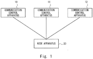
- Fig. 1 a description will be given of an exemplary configuration of a communication system according to a first embodiment of the present invention.
- the communication system shown in Fig. 1 includes communication control apparatuses 10 to 12 and a node apparatus 20. While Fig. 1 shows that the node apparatus 20 is connected to the communication control apparatuses 10 to 12, the node apparatus 20 may be connected to two or more than three communication control apparatuses.
- the communication control apparatuses 10 to 12 may each be a computer apparatus which operates by a CPU (Central Processing Unit) executing a program stored in memory. Further, the communication control apparatuses 10 to 12 may be MMEs or SGSNs (Serving GPRS Support Nodes) defined in the 3GPP (the 3rd Generation Partnership Project).
- the node apparatus 20 executes, with the communication control apparatuses 10 to 12, control processing including call processing relating to a communication terminal.
- the call processing corresponds to, for example, control processing such as route configuration in a core network that is executed when a communication terminal establishes a voice call or data communications or the like.
- the node apparatus 20 may be a computer apparatus that operates by a CPU (Central Processing Unit) executing a program stored in memory. Further, the node apparatus 20 may be an eNB (evolved Node B), an RNC (Radio Network Controller), an S-GW (Serving Gateway), an HSS (Home Subscriber Server) or the like defined in the 3GPP.
- eNB evolved Node B
- RNC Radio Network Controller
- S-GW Serving Gateway
- HSS Home Subscriber Server
- the communication terminal may be, for example, a mobile phone, a smartphone, or a tablet terminal having a communication function. Further, the communication terminal may be a computer apparatus such as a personal computer.
- the communication control apparatuses 10 to 12 form a context sharing group that shares subscriber data of the communication terminal.
- the communication control apparatuses 10 to 12 sharing the subscriber data means that any subscriber data available to the communication control apparatus 10 is also available to the communication control apparatuses 11 and 12.
- the communication control apparatuses 10 to 12 may retrieve subscriber data as appropriate from the server apparatus.
- the communication control apparatuses may transmit and receive subscriber data between each other, thereby acquiring subscriber data retained by another communication control apparatus.
- the node apparatus 20 executes call processing or control processing relating to a communication terminal, the node apparatus 20 selects any communication control apparatus in the context sharing group. Further, the node apparatus 20 transmits, to the selected communication control apparatus, a call processing message or a control message.
- the call processing message may be, for example, a control message defined in the 3GPP.
- the 3GPP defines various control messages, for example, an Attach Request message that is transmitted when the power of the communication terminal transits to the ON state.
- the node apparatus selects one communication control apparatus based on information which it has been notified about by the communication control apparatuses (e.g., the congestion status of each of the communication control apparatuses, the capacity of each of the communication control apparatuses, information on the subscriber data shared among the communication control apparatuses (the context sharing group)).
- information which it has been notified about by the communication control apparatuses e.g., the congestion status of each of the communication control apparatuses, the capacity of each of the communication control apparatuses, information on the subscriber data shared among the communication control apparatuses (the context sharing group)).
- the communication control apparatuses belonging to the context sharing group can share the subscriber data of the communication terminal. Accordingly, the node apparatus can execute call processing or control processing of a communication terminal with any selected one of the communication control apparatuses belonging to the context sharing group.
- the node apparatus 20 can dynamically change the communication control apparatus to serve in communication in executing call processing or control processing. Accordingly, the node apparatus 20 can change the communication control apparatus, for example, depending on the load condition of the communication control apparatuses. As a result, the node apparatus 20 can exert load balancing control among the plurality of communication control apparatuses. Further, the node apparatus can distribute, on a subscriber-by-subscriber basis, call processing messages or control messages over the communication control apparatus sharing the subscriber data. Accordingly, as compared to the case where messages are distributed on a node apparatus-by-node apparatus basis, the above node apparatus can distribute messages more properly by finer division among the communication control apparatuses.
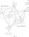
- the communication system in Fig. 2 is configured by the apparatuses defined in the 3GPP.
- the communication system in Fig. 2 includes MMEs 30 to 60, an eNB 70, an HSS 80, an S-GW 90, a P-GW (Packet Data Network-Gateway) 100, and an UE (User Equipment) 110.
- the MMEs 30 to 60 correspond to the communication control apparatuses in Fig. 1 .
- the eNB 70, the HSS 80, and the S-GW 90 correspond to the node apparatus in Fig. 1 .
- the UE 110 corresponds to the communication terminal.
- the MMEs may be replaced by SGSNs defined in the 3GPP, and the eNB may be replaced by an RNC defined in the 3GPP.
- the MME 30 and the MME 40 belong to a context sharing group A, and the MME 50 and the MME 60 belong to a context sharing group B. Further, the MMEs 30 to 60 may belong to an MME group which is not a context sharing group.
- the MME group is formed by MMEs which are candidates for the first MME at which the eNB 70 generates context information.
- the context information corresponds to the subscriber data described with reference to Fig. 1 . That is, the MME group may include a plurality of context sharing groups. Alternatively, the MMEs belonging to the MME group and the MMEs belonging to the context sharing group may be identical to each other.
- the eNB 70 determines to generate context information relating to the UE 110 firstly at the MME 30, the eNB 70 selects the MME 30 in every following step in the call processing. In contrast, in the embodiments of the present invention, even if the eNB 70 firstly generates context information at the MME 30, the eNB 70 can select the MME 30 or the MME 40 in any later step in the call processing. Further, the HSS 80 and the S-GW 90 are also capable of executing call processing by selecting an MME which is different from the MME at which the context information was firstly generated.
- the MMEs 40 to 60 are substantially configured identically to the MME 30 and, therefore, a detailed description thereof will not be repeated.
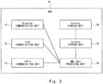
- the MME 30 includes a Diameter communication unit 31, an S1AP (S1 Application) communication unit 32, a GTP (General packet radio service Tunneling Protocol) - C communication unit 33, a context sharing unit 34, a context storing unit 35, and an MME call processing unit 36.
- the Diameter communication unit 31 is used as the interface between the MME 30 and the HSS 80.
- the S1AP communication unit 32 is used as the interface between the MME 30 and the eNB 70.
- the GTP-C communication unit 33 is used as the interface between the MME 30 and the S-GW 90.
- the context sharing unit 34 retrieves the context information of the UE 110 being the target of the call processing. For example, when the server apparatus or the like manages the context information generated at an MME belonging to the context sharing group A, the context sharing unit 34 may retrieve the context information of the call processing-target UE 110 from the server apparatus. Alternatively, the context sharing unit 34 may retrieve the context information of the call processing-target UE 110 from the MME 40 belonging to the context sharing group A.
- the context storing unit 35 stores the context information retrieved by the context sharing unit 34 and the context information generated by the MME 30.
- the context storing unit 35 may be, for example, memory inside the MME 30, or may be an external memory apparatus or the like attached to the MME 30.
- the context information may be shared by a plurality of MMEs by the HSS 80 retaining the context information and the plurality of MMEs making access to the HSS 80 as necessary.
- the context storing unit 35 retains information on the context sharing group to which the MME 30 belongs.
- the context storing unit 35 retains information representing the context sharing group A.
- the context storing unit 35 may be, for example, memory inside the MME 30, or an external memory apparatus or the like attached to the MME 30.
- the information retained by the context storing unit 35 may be shared by a plurality of MMEs by the HSS 80 retaining the context storing unit 35 and the plurality of MMEs making access to the HSS 80 as necessary.
- the MME call processing unit 36 executes call processing using the context information and the information representing the context sharing group A stored in the context storing unit 35.
- the MME call processing unit 36 transmits and receives messages relating to call processing with the eNB 70, the HSS 80, or the S-GW 90, via the Diameter communication unit 31, the S1AP communication unit 32, or the GTP-C communication unit 33.
- the eNB 70 includes an S1AP communication unit 71, an S1AP call processing unit 72, an RRC (Radio Resource Control) processing unit 73, a radio processing unit 74, a GTP-U communication unit 75, a GTP-U processing unit 76, and a context storing unit 77.
- S1AP communication unit 71 an S1AP call processing unit 72
- RRC Radio Resource Control
- the S1AP communication unit 71 is used as the interface in communicating with the MMEs 30 to 60.
- the S1AP call processing unit 72 executes call processing between the eNB 70 and the MMEs 30 to 60 using information stored in the context storing unit 77.
- the S1AP call processing unit 72 transmits and receives messages relating to call processing between the eNB 70 and the MMEs 30 to 60 via the S1AP communication unit 71. Further, the S1AP call processing unit 72 selects, using information stored in the context storing unit 77, an MME with which the call processing is executed.
- the RRC (Radio Resource Control) processing unit 73 executes a process relating to the RRC protocol used with the UE 110.
- the RRC processing unit 73 may execute a process of managing the connection state relative to the UE 110.
- the radio processing unit 74 is used as the interface in wirelessly communicating with the UE 110.
- the GTP-U communication unit 75 is used as the interface in communicating with the S-GW 90.
- the GTP-U processing unit 76 transmits and receives user data with the S-GW 90 via the GTP-U communication unit 75.
- the context storing unit 77 stores information on the context sharing group received from the MMEs 30 to 60.
- the context storing unit 77 stores the context sharing group and the MMEs belonging to the group in association with each other.
- the context storing unit 77 may store a WF (Weight Factor) which is referred to in selecting the MMEs, in association with the MMEs.
- WF Weight Factor
- the S-GW 90 includes a GTP-C communication unit 91, a GTP-U communication unit 92, a GTP-C processing unit 93, a context storing unit 94, and a GTP-U processing unit 95.
- the GTP-C communication unit 91 is used as the interface in communicating with the MMEs 30 to 60.
- the GTP-U communication unit 92 is used as the interface in communicating with the eNB 70.
- the GTP-C processing unit 93 transmits and receives messages relating to call processing between the S-GW 90 and the MMEs 30 to 60 via the GTP-C communication unit 91. Further, the GTP-C processing unit 93 selects, using information stored in the context storing unit 94, an MME with which the call processing is executed.
- the GTP-U processing unit 95 transmits and receives user data with the eNB 70 via the GTP-U communication unit 92.
- the context storing unit 94 stores information on the context sharing group received from the MMEs 30 to 60.
- the context storing unit 77 stores the context sharing group and the MMEs belonging to the group in association with each other.
- the context storing unit 94 may store the WF which is referred to in selecting the MMEs, in association with the MMEs.
- the HSS 80 includes a Diameter communication unit 81, a subscriber information processing unit 82, and a subscriber information storing unit 83.
- the Diameter communication unit 81 is used as the interface in communicating with the MMEs 30 to 60.
- the subscriber information storing unit 83 stores information on the context sharing group received from the MMEs 30 to 60.
- the subscriber information storing unit 83 stores the context sharing group and the MMEs belonging to the group in association with each other. Further, the subscriber information storing unit 83 may store the WF which is referred to in selecting the MMEs, in association with the MMEs.
- the subscriber information processing unit 82 transmits and receives messages relating to call processing between the HSS 80 and the MMEs 30 to 60 via the Diameter communication unit 81. Further, the subscriber information processing unit 82 selects, using information stored in the subscriber information storing unit 83, an MME with which the call processing is executed.
- the eNB 70 transmits an S1 SETUP REQUEST message to every MME in the MME group in order to establish an S1 connection (S11).
- the MMEs each transmit an S1 SETUP RESPONSE message to the eNB 70 (S12).
- Each of the MMEs set, on its S1 SETUP RESPONSE message, the context sharing group to which the MME belongs, a GUMMEI (Globally Unique MME Identifier), and a WF (Weight Factor).
- the GUMMEI is identification information for uniquely identifying each of the MMEs.
- the WF is priority information that the eNB 70 uses in selecting an MME with which call processing is executed. For example, the eNB 70 may frequently select an MME with a higher WF value, and less frequently select an MME with a lower WF value.
- the eNB 70 retains the information set on the S 1 SETUP RESPONSE message.
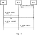
- the MME 30 and the MME 40 undergo a representative selecting process of determining which one of the MME 30 and the MME 40 is the representative MME (S20).
- the representative selecting process is executed among a plurality of MMEs belonging to an identical context sharing group. For example, as the representative MME, the MME with lower-number identification information may be selected.
- the representative MME may be selected based on other criterion. Here, it is assumed that the MME 30 is selected as the representative MME. Further, in the representative selecting process, the MME 40 and others which are not the representative MME may transmit their own information such as the GUMMEI and the WF to the representative MME.
- the eNB 70 transmits an S1 SETUP REQUEST message to every MME in the MME group in order to establish an S1 connection (S21).
- S21 S1 connection
- Fig. 8 shows that the eNB 70 transmits the S 1 SETUP REQUEST message to the MME 30 and the MME 40, it is to be understood that the eNB 70 transmits the S1 SETUP REQUEST message to every MME in the MME group.
- the MME 30 being the representative MME transmits, to the eNB 70, an S1 SETUP RESPONSE message, setting thereon the context sharing group, the GUMMEI of every MME belonging to the context sharing group, and the WF of every MME (S22).
- the MME 40 not being the representative MME transmits an S1 SETUP RESPONSE message to the eNB 70 in order to establish an S1 connection.
- information on the context sharing group may not be set.
- an EMS (Element Management System) apparatus registers, on the eNB 70, information on the context sharing group, the GUMMEI of every MME belonging to the context sharing group, and the WF of every MME (S31).
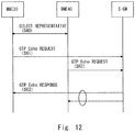
- each of the MMEs transmits a GTP Echo REQUEST message to the S-GW 90, setting thereon the context sharing group to which the MME belongs and the WF (S41).
- the S-GW 90 identifies each MME using the IP address of the sender of the GTP Echo REQUEST message.
- the S-GW 90 retains the information set on the GTP Echo REQUEST message.
- the S-GW 90 transmits a GTP Echo RESPONSE message to each of the MMEs (S42).
- the GTP Echo REQUEST message and the GTP Echo RESPONSE message are used for determining whether or not any failure is occurring between the MMEs and the S-GW.
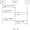
- the S-GW 90 transmits a GTP Echo REQUEST message to each of the MMEs (S51).
- each of the MMEs transmits a GTP Echo RESPONSE message to the S-GW 90, setting thereon the context sharing group to which the MME belongs and the WF (S52).
- the MME 30 and the MME 40 undergo a representative selecting process of determining which one of the MME 30 and the MME 40 is the representative MME (S60).
- the representative selecting process is executed among a plurality of MMEs belonging to an identical context sharing group.
- the MME 30 is selected as the representative MME.
- the MME 30 being the representative MME transmits a GTP Echo REQUEST message to the S-GW 90, setting thereon the context sharing group and the WF of every MME belonging to the context sharing group (S61).
- the MME 30 may set the IP address being the identification information of each MME belonging to the context sharing group and the WF in association with each other.
- the MME 40 not being the representative MME transmits a normal GTP Echo REQUEST message to the S-GW 90 (S62).
- the S-GW 90 transmits a GTP Echo RESPONSE message to each of the MMEs (S63).
- the MME 30 and the MME 40 undergo the representative selecting process (S70).
- the S-GW 90 transmits a GTP Echo REQUEST message to every MME in the MME group (S71).
- the MME 30 being the representative MME transmits a GTP Echo REQUEST message to the S-GW 90, setting thereon the context sharing group and the WF of every MME belonging to the context sharing group (S72).
- the MME 40 As a response message to the GTP Echo REQUEST message, the MME 40 not being the representative MME transmits a normal GTP Echo RESPONSE message to the S-GW 90 (S73).
- the EMS (Element Management System) apparatus registers, on the S-GW 90, information on the context sharing group and the WF of every MME belonging to the context sharing group (S81).
- the MMEs each establish an SCTP (Stream Control Transmission Protocol) Connection with the HSS 80 (S90).
- SCTP Stream Control Transmission Protocol
- the MMEs each transmit, to the HSS 80, an Update Context Shared Group REQUEST message, setting thereon the context sharing group to which the MME belong, an Origin-Host, and the WF (S91).
- the Origin-Host is information that identifies the MMEs.
- the HSS 80 retains the information set on the Update Context Shared Group REQUEST message.
- the HSS 80 transmits an Update Context Shared Group ANSWER message to each of the MMEs (S92).
- the MME 30 and the MME 40 establish an SCTP Connection (S100).
- the MME 30 and the MME 40 undergo the representative selecting process of determining which one of the MME 30 and the MME 40 is the representative MME (S101).
- the representative selecting process is executed among a plurality of MMEs belonging to an identical context sharing group.
- the MME 30 being the representative MME transmits, to the HSS 80, an Update Context Shared Group REQUEST message, setting thereon the context sharing group, the Origin-Host of every MME belonging to the context sharing group, and the WF of every MME belonging to the context sharing group (S102).
- the HSS 80 transmits an Update Context Shared Group ANSWER message to the MME 30 (S103).
- the EMS (Element Management System) apparatus registers, on the HSS 80, information on the context sharing group and the WF of every MME belonging to the context sharing group (S111).
- the eNB 70, the S-GW 90, and the HSS 80 having received the information on the context sharing group manage the information on the context sharing group as shown in Fig. 18 .
- the context sharing groups and the MMEs belonging to respective context sharing groups are managed in association with each other. Further, the values of the WF set on the MMEs are also managed in association with respective MMEs.
- the MME 30 to the MME #N belong to a context sharing group A
- the MME 50 and the MME 60 belong.
- the management information shows that the MME 30 belongs to the context sharing group A, and has a value of 50 as the WF.
- information that identifies the MME may be different depending on the type of the node.
- the eNB may use the GUMMEI as the identification information of the MMEs;
- the SGW may use the IP address as the identification information of the MMEs; and
- the HSS may use the Origin-Host as the identification information of the MMEs.
- the UE 110 transmits an NAS (Non-Access Stratum): Attach Request message to the eNB 70 (S121).
- the UE 110 sets a GUTI (Globally Unique Temporary Identifier) on the NAS: Attach Request message.
- the GUTI is information formed by the GUMMEI and an M-TMSI (Temporary Mobile Subscriber Identity).
- the GUTI is temporary identification information used for uniquely identifying the UE.
- the eNB 70 selects an MME to be the destination of the NAS: Attach Request message (S122).
- the eNB 70 specifies the GUMMEI from the GUTI set on the NAS: Attach Request message.
- the GUMMEI specified based on the GUTI represents the MME at which context information relating to the UE 110 was generated or the MME that was selected by the eNB in the previous Attach process.
- the eNB 70 can specify, based on the management information shown in Fig. 18 , the context sharing group to which the MME identified by the GUMMEI belongs.
- the eNB 70 selects an MME according to the WF out of the MMEs belonging to the specified context sharing group. In Fig. 19 , it is assumed that the eNB 70 selects the MME 30.
- the eNB 70 transmits an NAS: Attach REQUEST/S1AP: Initial UE message to the selected MME (S123).
- the MME 30 selects an Authentication Information REQUEST message to the HSS 80 (S124).
- the HSS 80 selects an MME to be the destination of an Authentication Information ANSWER message on which the AV is set (S125).
- the HSS 80 specifies the context sharing group to which the MME 30 being the sender of the Authentication Information REQUEST message belongs, using the management information shown in Fig. 18 .
- the HSS 80 selects, out of the MMEs belonging to the specified context sharing group, an MME according to the WF. In Fig. 19 , it is assumed that the HSS 80 selects the MME #N. It is assumed that the MME #N belongs to the context sharing group A to which the MME 30 similarly belongs.
- the HSS 80 transmits the Authentication Information ANSWER message to the selected MME #N (S126). In this manner, the HSS 80 can transmit the Authentication Information ANSWER message to the MME #N which is not the MME 30 being the sender of the Authentication Information REQUEST message.
- the MME #N transmits an Authentication REQUEST message to the eNB 70 (S127).
- the MME 30 transmits a Create Session REQUEST message to the S-GW 90 (S128).
- the S-GW 90 selects an MME to be the destination of a Create Session RESPONSE message (S129).
- the S-GW 90 specifies the context sharing group to which the MME 30 being the sender of the Create Session REQUEST message belongs, using the management information shown in Fig. 18 .
- the S-GW 90 selects, out of the MMEs belonging to the specified context sharing group, an MME according to the WF. In Fig. 20 , it is assumed that the S-GW 90 selects the MME #N.
- the S-GW 90 transmits the Create Session RESPONSE message to the selected MME #N (S130). In this manner, the S-GW 90 can transmit the Create Session RESPONSE message to the MME #N which is not the MME 30 being the sender of the Create Session REQUEST message.
- the MME #N transmits an NAS: Attach Accept/S1AP: Initial Context Setup REQUEST message to the eNB 70 (S131).
- the eNB 70 can receive the NAS: Attach Accept message from the MME #N which is not the MME 30 being the destination of the NAS: Attach REQUEST message.
- the eNB 70 transmits an NAS: Attach Accept message to the UE 110 (S132).
- the eNB 70 receives the S1AP: Initial Context Setup REQUEST message in step S131, the eNB 70 selects an MME to be the destination of an S1AP: Initial Context Setup RESPONSE message (S133).
- S133 Initial Context Setup RESPONSE message
- the eNB 70 transmits the S1AP: Initial Context Setup RESPONSE message to the selected MME #N.
- the eNB 70 can transmit the S1AP: Initial Context Setup RESPONSE message to the MME #N which is not the MME 30 being the destination of the NAS: Attach REQUEST message in step S123.
- the MME #N transmits a Modify Bearer REQUEST message to the S-GW 90 (S135).
- the S-GW 90 operates similarly in step S129 in order to select an MME to be the destination of the Modify Bearer RESPONSE message (S136).
- the S-GW 90 selects the MME 30.
- the S-GW 90 transmits the Modify Bearer RESPONSE message to the selected MME 30.
- an MME can share the context information relating to the UE with other MME belonging to an identical context sharing group. Accordingly, even if a call processing message is transmitted by the eNB, the S-GW, and the HSS to an arbitrary MME belonging to the context sharing group, the call processing of the UE can be continued.
- the eNB, the S-GW, and the HSS being the node apparatuses around the MMEs can transmit a call processing message to any MME belonging to the context sharing group in performing the call processing of the UE. Accordingly, the eNB, the S-GW, and the HSS achieve load balancing in call processing executed at the MMEs.
- the MME that transmits the S 1 SETUP REQUEST message may be, for example, the MME selected as the representative before the additionally installed MME belongs to the context sharing group, or may be the MME receiving information on the additionally installed MME from the administrator or the like. Further, when the additionally installed MME and the preexisting MME undergo the representative selecting process and the additionally installed MME is selected as the representative MME, the additionally installed MME may transmit the S1 SETUP REQUEST message.
- the EMS apparatus may register, on the eNB 70, information on the additionally installed MME.
- the eNB 70 may transmit the S1 SETUP REQUEST message to every MME or just the additionally installed MME.
- the additionally installed MME transmits, to the S-GW 90, a GTP Echo REQUEST message, setting thereon the context sharing group to which the additionally installed MME belongs and the WF (S161).
- the S-GW 90 manages the information shown in Fig. 18 .
- the S-GW 90 adds, to the information shown in Fig. 18 , the information on the additionally installed MME, thereby updating the management information (S162).
- the S-GW 90 transmits a GTP Echo RESPONSE message to the additionally installed MME (S163).
- the representative MME is selected out of the context sharing group to which the additionally installed MME belongs (S171).
- the MME #N is selected as the representative MME.
- the representative MME transmits, to the S-GW 90, a GTP Echo REQUEST message, setting thereon the context sharing group and the WF of every MME belonging to the context sharing group (S172).
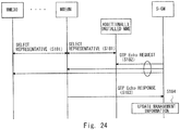
- Steps S173 and S174 are similar to steps S162 and S163 in Fig. 22 and, therefore, the detailed description thereof will not be repeated. Note that, in step S174, the S-GW 90 transmits a GTP Echo REQUEST message to the representative MME.
- Step S181 is similar to step S171 in Fig. 23 and, therefore, the detailed description thereof will not be repeated.
- the S-GW 90 transmits a GTP Echo REQUEST message to every MME belonging to the MME group (S182).
- the representative MME transmits, to the S-GW 90, a GTP Echo RESPONSE message, setting thereon the context sharing group and the WF of every MME belonging to the context sharing group (S183).
- other MME not being the representative MME may also transmit a GTP Echo RESPONSE message to the S-GW 90, without setting thereon information such as the context sharing group.
- Step S184 is similar to step S173 in Fig. 23 and, therefore, the detailed description thereof will not be repeated.
- the EMS apparatus may register, on the S-GW 90, information on the additionally installed MME as shown in Fig. 14 .
- the information on the additionally installed MME may be transmitted to the S-GW 90 using a novel message not currently defined in the 3GPP.
- the eNB 70, the S-GW 90, and the HSS 80 can keep track of the MME being additionally installed, and update the management information.
- the eNB 70, the S-GW 90, and the HSS 80 can perform call processing using the additionally installed MME. That is, the eNB 70, the S-GW 90, and the HSS 80 can dynamically transmit a call processing message to the additionally installed MME.
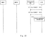
- an uninstallation-target MME starts an uninstalling process (S191).
- the uninstalling process of the MME may be, for example, turning OFF the power of the MME, or shutting down the MME.
- the S1AP connection between the uninstalled MME and the eNB 70 is disconnected.
- the eNB 70 detects the disconnection of the SLAP (S192).
- the eNB 70 deletes the information on the uninstalled MME from the management information described with reference to Fig. 18 , thereby updating the management information (S193).
- the eNB 70 may also disconnect the RRC connection.
- Fig. 25 While the description with reference to Fig. 25 has been given of the case where the MME is uninstalled, the processing flow shown in Fig. 25 is also applicable to the case where any MME has failed.
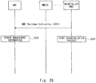
- the uninstallation-target MME Before starting the uninstalling process, the uninstallation-target MME transmits an MME Shutdown Indication message to the eNB 70 (S201).
- the uninstallation-target MME transmits the MME Shutdown Indication message to the eNB 70 in order to notify of the start of the uninstalling process.
- the MME Shutdown Indication message may be a message called by a different name.
- the uninstallation-target MME may set, on the MME Shutdown Indication message, the context sharing group, the GUMMEI, and the shutdown time.
- the shutdown time may be, for example, information representing the time point at which the uninstallation-target MME starts the uninstalling process, or the remaining seconds until the MME starting the uninstalling process.
- the uninstallation-target MME transmitting the shutdown time to the eNB 70 prevents, for example, call blocking due to sudden uninstallation of the MME.
- the eNB 70 having received the MME Shutdown Indication message may put higher priority on the call processing with the uninstallation-target MME.
- the S-GW 90 periodically transmits a GTP Echo REQUEST message to the MME in order to check whether or not the S-GW 90 is normally connected to the MME (S211).
- the S-GW 90 will not receive a response signal to the transmitted GTP Echo REQUEST message. Accordingly, the S-GW 90 repeats transmission of the GTP Echo REQUEST message (S212).
- the S-GW 90 determines that the MME has been uninstalled or the MME has been failed. In this case, the S-GW 90 deletes the entry of the MME whose uninstallation or failure is determined, thereby updating the management information in Fig. 18 (S213).
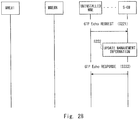
- the uninstallation-target MME Before starting the uninstalling process, the uninstallation-target MME transmits a GTP Echo REQUEST message to the S-GW 90, setting thereon information of the uninstallation (S221).
- the uninstallation-target MME may set, on the GTP Echo REQUEST message, for example, the context sharing group to which the uninstallation-target MME belongs, an uninstallation flag indicative of uninstallation or the like, as a new IE (Information Element).
- the S-GW 90 upon receipt of the GTP Echo REQUEST message in step S221, the S-GW 90 deletes the entry of the MME to be uninstalled, thereby updating the management information in Fig. 18 (S222).
- the S-GW 90 transmits a GTP Echo RESPONSE message to the uninstallation-target MME (S223).
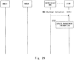
- the uninstallation-target MME notifies the S-GW 90 of the uninstallation by transmitting a GTP Echo REQUEST message.
- the uninstallation-target MME notifies the S-GW 90 of the uninstallation by transmitting an MME Shutdown Indication message.
- the uninstallation-target MME may set, on the MME Shutdown Indication message, the context sharing group and the shutdown time.
- the shutdown time may be, for example, information representing the time point at which the uninstallation-target MME starts the uninstalling process, or the remaining seconds until the MME starting the uninstalling process.
- the S-GW 90 deletes the entry of the MME to be uninstalled, thereby updating the management information in Fig. 18 (S232).
- the S-GW 90 ends the process without transmitting a response message to the MME Shutdown Indication message.
- the EMS apparatus may register, on the S-GW 90, information on the uninstalled MME as shown in Fig. 14 .
- information on the uninstalled MME may be transmitted to the S-GW 90 using a novel message not currently defined in the 3GPP.
- an uninstallation-target MME starts an uninstalling process (S241).
- the uninstalling process of the MME may be, for example, turning OFF the power of the MME, or shutting down the MME.
- the HSS 80 Upon the uninstalling process of the MME, the SCTP connection between the uninstalled MME and the HSS 80 is disconnected. At this time, the HSS 80 detects the disconnection of the SCTP (S242). Next, the HSS 80 deletes the information on the uninstalled MME from the management information described with reference to Fig. 18 , thereby updating the management information (S243).
- the uninstallation-target MME Before starting the uninstalling process, the uninstallation-target MME transmits an MME Shutdown Indication message to the HSS 80 (S252).
- the uninstallation-target MME transmits the MME Shutdown Indication message to the HSS 80 in order to notify of the start of the uninstalling process.
- the MME Shutdown Indication message may be a message called by a different name.
- the uninstallation-target MME may set, on the MME Shutdown Indication message, the context sharing group, the Origin-Host, and the shutdown time.
- the shutdown time may be, for example, information representing the time point at which the uninstallation-target MME starts the uninstalling process, or the remaining seconds until the MME starting the uninstalling process.
- the uninstallation-target MME transmitting the shutdown time to the eNB 70 prevents, for example, call blocking due to sudden uninstallation of the MME.
- the HSS 80 having received the MME Shutdown Indication message may put higher priority on the call processing with the uninstallation-target MME.
- the uninstallation-target MME starts the uninstalling process at the timing indicated by the shutdown time (S252). Further, the HSS 80 deletes the entry of the uninstallation-target MME from the management information shown in Fig. 18 , thereby updating the management information.
- the eNB 70, the S-GW 90, and the HSS 80 can keep track of the MME being uninstalled, and update the management information. After updating the management information, the eNB 70, the S-GW 90, and the HSS 80 will not transmit a call processing message to the uninstalled MME.
- the uninstallation-target MME Normally, when an MME is to be uninstalled, the uninstallation-target MME must transfer its retaining context information of the UE to other MME. In such a case, in general, the MME causes the UE to Detach, and to again Attach, so that the context information of the UE is newly generated at other MME.
- the UE in communication is caused to Detach, unfortunately the communication of the UE in communication is temporarily interrupted.
- the MMEs share context information stored in an external server apparatus or the like. Accordingly, in the case where an MME is uninstalled, it is not necessary for the UE to Detach. Thus, with the communication system according to the fourth embodiment, any MME can be uninstalled without inviting an interruption of the communication of the UE.
- the context information in the case where the context information is stored in a server apparatus or the like, the context information will not be lost because of uninstallation of any MME. Accordingly, in place of the uninstalled MME, the remaining MMEs can continue call processing using the context information stored in the server apparatus or the like.
- Upscaling an MME means improving the performance of the MME
- downscaling an MME means lowering the performance of the MME.
- the upscaled MME can handle a greater amount of call processing.
- the upscaled MME is provided with an increased WF value, so as to enlarge the opportunity of the upscaled MME being selected by the surrounding node apparatuses.
- the downscaled MME is provided with a reduced WF value, so as to curtail the opportunity of the downscaled MME being selected by the surrounding node apparatuses.
- a description will be given of a processing flow of notifying the eNB 70 of any WF being changed due to upscaling or downscaling.
- the MME #N belongs to the context sharing group A is upscaled or downscaled (S261).
- the MME #N transmits an MME Configuration Update message to the eNB 70 (S262).
- the MME #N sets, on the MME Configuration Update message, the context sharing group, the GUMMEI, and the updated WF value.
- the eNB 70 updates, in the management information shown in Fig. 18 , the WF value of the MME #N (S263).
- the eNB 70 transmits an MME Configuration Update Acknowledge message to the MME #N.
- the representative MME belonging to the context sharing group A may transmit an MME Configuration Update message to the eNB 70.
- the representative MME may set, on the MME Configuration Update message, the context sharing group and the GUMMEI and the WF of every MME belonging to the context sharing group.
- the representative MME may set, on the MME Configuration Update message, the context sharing group, and the GUMMEI and the updated WF of any MME having its WF updated.
- the EMS apparatus may register, on the eNB 70, information on the updated WF of the MME #N.
- the MME sets the updated WF on a GTP Echo REQUEST message or a GTP Echo RESPONSE message.
- the EMS apparatus may register, on the S-GW 90, information on the updated WF of the upscaled or downscaled MME.
- the MME sets the updated WF on an Update Context Shared Group REQUEST message.
- the EMS apparatus may register, on the HSS 80, information on the updated WF of the upscaled or downscaled MME.
- the communication system according to the fifth embodiment of the present invention can dynamically exerts load balancing control on MMEs according to any change in performance of the MMEs.
- the WF may be changed upon occurrence of congestions at an MME. For example, when congestions has occurred at any MME, the MME with the congestions may have its WF value reduced. Thus, the opportunity of the MME being selected by the surrounding node apparatuses is curtailed, whereby congestions are avoided.
- Fig. 33 shows that the MME 30 is connected to the HSS 80 via an S6a interface. While Fig. 33 shows that the MME 30 is connected to the HSS 80, a plurality of MMEs are connected to the HSS 80 via the S6a interface.
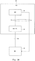
- Fig. 34 shows that the MME 30 is connected to an HSS-FE (Front End) 85 via the S6a interface, and connected to an UDR (User Data Repository) 86 via an Ud interface. Further, the HSS-FE 85 is connected to the UDR 86 via the Ud interface.
- HSS-FE Front End
- UDR User Data Repository
- the UDR 86 retains the subscriber data of the UE. Further, the HSS-FE 85 is disposed between the MME 30 and the UDR 86, to relay communication between the MME 30 and the UDR 86. In this manner, the configuration of the HSS 80 may be separated into the UDR 86 being the data storage, and the HSS-FE 85 operating as the interface in communicating with the MME 30.
- the eNB 70 selects an MME to be the destination of the NAS: Attach Request message (S271).
- the eNB 70 selects the MME 30.
- the eNB 70 transmits the NAS: Attach Request message to the selected MME 30 (S272).
- the MME 30 generates context information relating to the UE being the sender of the NAS: Attach Request message (S273).
- the MME 30 generates the context information when the HSS 80 does not store therein the context information relating to the UE being the sender of the NAS: Attach Request message.
- the MME 30 transmits a Context Put REQUEST message (S275).
- the HSS 80 or the like stores, in its own memory or the like, the context information set on the Context Put REQUEST message (S275).
- the HSS 80 or the like transmits a Context Put ANSWER message to the MME 30.
- the HSS 80 or the like does not select an arbitrary MME belonging to the context sharing group, but instead transmits the Context Put ANSWER message to the MME that has transmitted the Context Put REQUEST message.
- the MME 30 transmits an Authentication Information REQUEST message to the HSS 80 or the like (S277).
- the HSS 80 or the like transmits, to the MME 30, an Authentication Information Answer message, setting thereon the authentication vector of the specified UE.
- the MME 30 transmits a Context Put REQUEST message to the HSS 80 or the like.
- the HSS 80 or the like updates the context information so that the context information reflects the authentication vector of the UE stored in step S275 (S280).
- the HSS 80 transmits a Context Put ANSWER message to the MME 30 (S281).
- the MME 30 transmits an Authentication REQUEST message to the UE via the eNB 70 (S282).
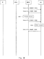
- the eNB 70 selects the MME to be the destination (S283).
- the eNB 70 selects the MME #N belonging to the context sharing group A.
- the eNB 70 transmits the Authentication RESPONSE message to the selected MME #N (S284).
- the MME #N transmits a Context Get REQUEST message to the HSS 80 or the like (S285).
- the HSS 80 transmits a Context Get ANSWER message to the MME #N, setting thereon the context information of the specified UE(S286).
- the MME #N authenticates the UE (S287).
- the MME #N transmits a Context Put REQUEST message to the HSS 80, setting thereon the context information (S288).
- the HSS 80 or the like updates the current context information using the context information set on the Context Put REQUEST message (S289).
- the HSS 80 or the like transmits a Context Put ANSWER message to the MME #N (S290).
- steps S277 to S281 in Fig. 35 show the operations of acquiring, from the HSS, an authentication vector required in authenticating the UE, and storing the authentication vector on the Context stored in the HSS 80. Accordingly, when the HSS 80 or the like stores the authentication vector on the stored context information, steps S277 to S281 can be dispensed with.
- the HSS can store the context information generated at the MME.
- a plurality of MMEs belonging to a context sharing group can each use the context information generated at other MME.
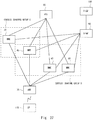
- the communication system shown in Fig. 37 is different from the communication system shown in Fig. 2 in MMEs belonging to a context sharing group.
- a description will be mainly given of the difference from the communication system shown in Fig. 2 .
- the MME 30 and the MME 40 belong to a context sharing group C. Further, the MME 40, the MME 50, and the MME 60 belong to a context sharing group D. That is, the MME 40 belongs to both the context sharing group C and the context sharing group D. In this manner, the MME may belong to a plurality of context sharing groups.
- information capable of specifying the context sharing group may be set on the GUMMEI.
- an MMEC region of the GUMMEI may be subdivided into an MMEC+ context sharing group ID.
- Attach Request message transmitted by the eNB 70 to the MME 40 a context sharing group may be specified.
- each of the MMEs belonging to a plurality of context sharing groups can also serve as an alternative apparatus in the context sharing groups.
Landscapes
- Engineering & Computer Science (AREA)
- Computer Networks & Wireless Communication (AREA)
- Signal Processing (AREA)
- Databases & Information Systems (AREA)
- Mobile Radio Communication Systems (AREA)
- Telephonic Communication Services (AREA)
- Data Exchanges In Wide-Area Networks (AREA)
Abstract
Description
- The present invention relates to communication systems and, particularly, to a communication system that selects a communication control apparatus out of a plurality of communication control apparatuses.
- The proliferation of smartphones and tablet terminals makes it necessary for MMEs (Mobile Management Entities) disposed in a core network to handle a vast variety of kinds of signaling generated by applications on these devices. Further, the characteristic of signaling greatly changes and unexpectable signaling increases depending on the time or place where communications are established; for example, in providing MTC (Machine Type Communication) services, in holding any events with crowds, or in disaster situations. To withstand such an environment, mobile communication providers must maintain service quality while avoiding an excessive investment and reducing TCO (Total Cost Ownership).
- Accordingly, what is demanded of MMEs is a mechanism that achieves dynamic load balancing in relation to signaling in accordance with the performance of the apparatuses, available resources, load conditions or the like. For example,
Non Patent Literature 1 discloses a scheme of signaling control at MMEs. Further,Patent Literature 1 discloses load balancing in order to avoid congestion at an MME by migrating service responsibilities to another MME on an eNB (evolved NodeB)-by-eNB basis. - Patent Literature 1: Published Japanese Translation of
PCT International Publication for Patent Application, No. 2014-533011 - Non Patent Literature 1: 3GPP TS 23.401 V13.1.0 (2014-12) 5.3.2 Attach procedure
- Here,
Non Patent Literature 1 discloses that, when information necessary in call processing, such as MM Context (subscriber data) relating to a communication terminal, is once generated at a specific MME, in performing call processing relating to that communication terminal, the MME where the information necessary in call processing was generated continues to be used. Accordingly, unfortunately,Non Patent Literature 1 fails to dynamically change the MME to serve in call processing in accordance with the load condition of the MMEs or the like. Further,Patent Literature 1 may fail to fully or properly achieve load balancing among MMEs because of its migrating service responsibilities on an eNB-by-eNB basis. - An object of the present invention is to solve the problems described above, and to provide a communication system, a communication control apparatus, a node apparatus, and a communication method capable of more effectively achieving load balancing among MMEs.
- A communication system according to a first aspect of the present invention includes: a plurality of communication control apparatuses; and a node apparatus that executes control processing including call processing relating to a communication terminal with the plurality of communication control apparatuses. The plurality of communication control apparatuses form a context sharing group that shares subscriber data of the communication terminal. The node apparatus selects a first communication control apparatus in the context sharing group, and transmits a call processing message to the first communication control apparatus. The first communication control apparatus executes the call processing using the subscriber data shared in the context sharing group.
- A communication control apparatus according to a second aspect of the present invention includes a context sharing unit that shares subscriber data of a communication terminal with other communication control apparatus belonging to a context sharing group, wherein, upon receipt of a call processing message from a node apparatus, the communication control apparatus executes call processing using the subscriber data shared in the context sharing group.
- A node apparatus according to a third aspect of the present invention executes, with a communication control apparatus, control processing including call processing relating to a communication terminal, wherein every time the node apparatus transmits a call processing message, the node apparatus selects a communication control apparatus out of a plurality of communication control apparatuses belonging to a context sharing group sharing subscriber data of the communication terminal, and transmits a control processing message including the call processing message to the selected communication control apparatus.
- A communication method according to a fourth aspect of the present invention is a communication method executed in a communication system that includes a plurality of communication control apparatuses and a node apparatus that executes control processing including call processing relating to a communication terminal with the plurality of communication control apparatuses. The plurality of communication control apparatuses form a context sharing group that shares subscriber data of the communication terminal. The node apparatus selects a first communication control apparatus in the context sharing group. The node apparatus transmits a call processing message to the selected first communication control apparatus. The first communication control apparatus executes the call processing using the subscriber data shared in the context sharing group.
- The present invention provides a communication system, a communication control apparatus, a node apparatus, and a communication method capable of more effectively achieving load balancing on MMEs in accordance with the load condition of the MMEs or the like.
-
-
Fig. 1 shows a configuration of a communication system according to a first embodiment. -
Fig. 2 shows a configuration of a communication system according to a second embodiment. -
Fig. 3 shows a configuration of an MME according to the second embodiment. -
Fig. 4 shows a configuration of an eNB according to the second embodiment. -
Fig. 5 shows a configuration of an S-GW according to the second embodiment. -
Fig. 6 shows a configuration of an HSS according to the second embodiment. -
Fig. 7 shows a processing flow of notifying information on a context sharing group from the MME to the eNB according to the second embodiment. -
Fig. 8 shows a processing flow of notifying information on the context sharing group from the MME to the eNB according to the second embodiment. -
Fig. 9 shows a processing flow of notifying information on the context sharing group from the MME to the eNB according to the second embodiment. -
Fig. 10 shows a processing flow of notifying information on the context sharing group from the MME to the S-GW according to the second embodiment. -
Fig. 11 shows a processing flow of notifying information on the context sharing group from the MME to the S-GW according to the second embodiment. -
Fig. 12 shows a processing flow of notifying information on the context sharing group from the MME to the S-GW according to the second embodiment. -
Fig. 13 shows a processing flow of notifying information on the context sharing group from the MME to the S-GW according to the second embodiment. -
Fig. 14 shows a processing flow of notifying information on the context sharing group from the MME to the S-GW according to the second embodiment. -
Fig. 15 shows a flow of notifying information on the context sharing group from the MME to the HSS according to the second embodiment. -
Fig. 16 shows a processing flow of notifying information on the context sharing group from the MME to the HSS according to the second embodiment. -
Fig. 17 shows a processing flow of notifying information on the context sharing group from the MME to the HSS according to the second embodiment. -
Fig. 18 shows management information managed by the eNB, the S-GW, and the HSS according to the second embodiment. -
Fig. 19 shows call processing according to the second embodiment. -
Fig. 20 shows call processing according to the second embodiment. -
Fig. 21 shows a processing flow of notifying the eNB of information on the context sharing group when an MME is additionally installed according to a third embodiment. -
Fig. 22 shows a processing flow of notifying the S-GW of information on the context sharing group when an MME is additionally installed according to the third embodiment. -
Fig. 23 shows a processing flow of notifying the S-GW of information on the context sharing group when an MME is additionally installed according to the third embodiment. -
Fig. 24 shows a processing flow of notifying the S-GW of information on the context sharing group when an MME is additionally installed according to the third embodiment. -
Fig. 25 shows a processing flow of notifying the eNB of information on the context sharing group when an MME is uninstalled according to the third embodiment. -
Fig. 26 shows a processing flow of notifying the eNB of information on the context sharing group when an MME is uninstalled according to a fourth embodiment. -
Fig. 27 shows a processing flow of notifying the S-GW of information on the context sharing group when an MME is uninstalled according to the fourth embodiment. -
Fig. 28 shows a processing flow of notifying the S-GW of information on the context sharing group when an MME is uninstalled according to the fourth embodiment. -
Fig. 29 shows a processing flow of notifying the S-GW of information on the context sharing group when an MME is uninstalled according to the fourth embodiment. -
Fig. 30 shows a processing flow of notifying the HSS of information on the context sharing group when an MME is uninstalled according to the fourth embodiment. -
Fig. 31 shows a processing flow of notifying the HSS of information on the context sharing group when an MME is uninstalled according to the fourth embodiment. -
Fig. 32 shows a processing flow of notifying the eNB of information on the context sharing group when a WF of an MME is changed according to a fifth embodiment. -
Fig. 33 illustrates an interface relating to the HSS according to a sixth embodiment. -
Fig. 34 illustrates an interface relating to the HSS according to the sixth embodiment. -
Fig. 35 shows a processing flow of storing context information according to the sixth embodiment. -
Fig. 36 shows a processing flow of storing the context information according to the sixth embodiment. -
Fig. 37 shows a configuration of a communication system according to a seventh embodiment. - In the following, with reference to the drawings, a description will be given of embodiments of the present invention. Firstly, with reference to
Fig. 1 , a description will be given of an exemplary configuration of a communication system according to a first embodiment of the present invention. The communication system shown inFig. 1 includescommunication control apparatuses 10 to 12 and anode apparatus 20. WhileFig. 1 shows that thenode apparatus 20 is connected to thecommunication control apparatuses 10 to 12, thenode apparatus 20 may be connected to two or more than three communication control apparatuses. - The
communication control apparatuses 10 to 12 may each be a computer apparatus which operates by a CPU (Central Processing Unit) executing a program stored in memory. Further, thecommunication control apparatuses 10 to 12 may be MMEs or SGSNs (Serving GPRS Support Nodes) defined in the 3GPP (the 3rd Generation Partnership Project). - The
node apparatus 20 executes, with thecommunication control apparatuses 10 to 12, control processing including call processing relating to a communication terminal. The call processing corresponds to, for example, control processing such as route configuration in a core network that is executed when a communication terminal establishes a voice call or data communications or the like. Thenode apparatus 20 may be a computer apparatus that operates by a CPU (Central Processing Unit) executing a program stored in memory. Further, thenode apparatus 20 may be an eNB (evolved Node B), an RNC (Radio Network Controller), an S-GW (Serving Gateway), an HSS (Home Subscriber Server) or the like defined in the 3GPP. - The communication terminal may be, for example, a mobile phone, a smartphone, or a tablet terminal having a communication function. Further, the communication terminal may be a computer apparatus such as a personal computer.
- The
communication control apparatuses 10 to 12 form a context sharing group that shares subscriber data of the communication terminal. Thecommunication control apparatuses 10 to 12 sharing the subscriber data means that any subscriber data available to thecommunication control apparatus 10 is also available to thecommunication control apparatuses communication control apparatuses 10 to 12 may retrieve subscriber data as appropriate from the server apparatus. Alternatively, the communication control apparatuses may transmit and receive subscriber data between each other, thereby acquiring subscriber data retained by another communication control apparatus. - When the
node apparatus 20 executes call processing or control processing relating to a communication terminal, thenode apparatus 20 selects any communication control apparatus in the context sharing group. Further, thenode apparatus 20 transmits, to the selected communication control apparatus, a call processing message or a control message. The call processing message may be, for example, a control message defined in the 3GPP. The 3GPP defines various control messages, for example, an Attach Request message that is transmitted when the power of the communication terminal transits to the ON state. The node apparatus selects one communication control apparatus based on information which it has been notified about by the communication control apparatuses (e.g., the congestion status of each of the communication control apparatuses, the capacity of each of the communication control apparatuses, information on the subscriber data shared among the communication control apparatuses (the context sharing group)). - The communication control apparatus selected by the
node apparatus 20, that is, the communication control apparatus which has received the call processing message or the control message transmitted by thenode apparatus 20, executes call processing or control processing using the subscriber data shared among the communication control apparatuses belonging to the context sharing group. For example, when the communication control apparatus selected by thenode apparatus 20 retains therein the subscriber data of the communication terminal which is the call processing-target, the communication control apparatus executes call processing or control processing using the retained subscriber data. When the communication control apparatus selected by thenode apparatus 20 does not retain therein the subscriber data of the communication terminal which is the call processing-target, the communication control apparatus may retrieve the subscriber data managed by the server apparatus, or may retrieve the subscriber data from another communication control apparatus. - As has been described above, with the communication system in
Fig. 1 , the communication control apparatuses belonging to the context sharing group can share the subscriber data of the communication terminal. Accordingly, the node apparatus can execute call processing or control processing of a communication terminal with any selected one of the communication control apparatuses belonging to the context sharing group. - Thus, the
node apparatus 20 can dynamically change the communication control apparatus to serve in communication in executing call processing or control processing. Accordingly, thenode apparatus 20 can change the communication control apparatus, for example, depending on the load condition of the communication control apparatuses. As a result, thenode apparatus 20 can exert load balancing control among the plurality of communication control apparatuses. Further, the node apparatus can distribute, on a subscriber-by-subscriber basis, call processing messages or control messages over the communication control apparatus sharing the subscriber data. Accordingly, as compared to the case where messages are distributed on a node apparatus-by-node apparatus basis, the above node apparatus can distribute messages more properly by finer division among the communication control apparatuses. - In the following, with reference to
Fig. 2 , a description will be given of an exemplary configuration of a communication system according to a second embodiment of the present invention. The communication system inFig. 2 is configured by the apparatuses defined in the 3GPP. The communication system inFig. 2 includesMMEs 30 to 60, aneNB 70, anHSS 80, an S-GW 90, a P-GW (Packet Data Network-Gateway) 100, and an UE (User Equipment) 110. TheMMEs 30 to 60 correspond to the communication control apparatuses inFig. 1 . TheeNB 70, theHSS 80, and the S-GW 90 correspond to the node apparatus inFig. 1 . TheUE 110 corresponds to the communication terminal. - Further, the MMEs may be replaced by SGSNs defined in the 3GPP, and the eNB may be replaced by an RNC defined in the 3GPP.
- In
Fig. 2 , theMME 30 and theMME 40 belong to a context sharing group A, and theMME 50 and theMME 60 belong to a context sharing group B. Further, theMMEs 30 to 60 may belong to an MME group which is not a context sharing group. The MME group is formed by MMEs which are candidates for the first MME at which theeNB 70 generates context information. The context information corresponds to the subscriber data described with reference toFig. 1 . That is, the MME group may include a plurality of context sharing groups. Alternatively, the MMEs belonging to the MME group and the MMEs belonging to the context sharing group may be identical to each other. - In general, when the
eNB 70 determines to generate context information relating to theUE 110 firstly at theMME 30, theeNB 70 selects theMME 30 in every following step in the call processing. In contrast, in the embodiments of the present invention, even if theeNB 70 firstly generates context information at theMME 30, theeNB 70 can select theMME 30 or theMME 40 in any later step in the call processing. Further, theHSS 80 and the S-GW 90 are also capable of executing call processing by selecting an MME which is different from the MME at which the context information was firstly generated. - In the following, with reference to
Fig. 3 , a description will be given of an exemplary configuration of theMME 30 according to the second embodiment of the present invention. TheMMEs 40 to 60 are substantially configured identically to theMME 30 and, therefore, a detailed description thereof will not be repeated. - The
MME 30 includes aDiameter communication unit 31, an S1AP (S1 Application)communication unit 32, a GTP (General packet radio service Tunneling Protocol) -C communication unit 33, acontext sharing unit 34, acontext storing unit 35, and an MMEcall processing unit 36. TheDiameter communication unit 31 is used as the interface between theMME 30 and theHSS 80. TheS1AP communication unit 32 is used as the interface between theMME 30 and theeNB 70. The GTP-C communication unit 33 is used as the interface between theMME 30 and the S-GW 90. - The
context sharing unit 34 retrieves the context information of theUE 110 being the target of the call processing. For example, when the server apparatus or the like manages the context information generated at an MME belonging to the context sharing group A, thecontext sharing unit 34 may retrieve the context information of the call processing-target UE 110 from the server apparatus. Alternatively, thecontext sharing unit 34 may retrieve the context information of the call processing-target UE 110 from theMME 40 belonging to the context sharing group A. - The
context storing unit 35 stores the context information retrieved by thecontext sharing unit 34 and the context information generated by theMME 30. Thecontext storing unit 35 may be, for example, memory inside theMME 30, or may be an external memory apparatus or the like attached to theMME 30. Alternatively, the context information may be shared by a plurality of MMEs by theHSS 80 retaining the context information and the plurality of MMEs making access to theHSS 80 as necessary. - Further, the
context storing unit 35 retains information on the context sharing group to which theMME 30 belongs. Here, thecontext storing unit 35 retains information representing the context sharing group A. Thecontext storing unit 35 may be, for example, memory inside theMME 30, or an external memory apparatus or the like attached to theMME 30. Alternatively, the information retained by thecontext storing unit 35 may be shared by a plurality of MMEs by theHSS 80 retaining thecontext storing unit 35 and the plurality of MMEs making access to theHSS 80 as necessary. - The MME
call processing unit 36 executes call processing using the context information and the information representing the context sharing group A stored in thecontext storing unit 35. The MMEcall processing unit 36 transmits and receives messages relating to call processing with theeNB 70, theHSS 80, or the S-GW 90, via theDiameter communication unit 31, theS1AP communication unit 32, or the GTP-C communication unit 33. - In the following, with reference to
Fig. 4 , a description will be given of an exemplary configuration of theeNB 70 according to the second embodiment of the present invention. TheeNB 70 includes anS1AP communication unit 71, an S1APcall processing unit 72, an RRC (Radio Resource Control)processing unit 73, aradio processing unit 74, a GTP-U communication unit 75, a GTP-U processing unit 76, and acontext storing unit 77. - The
S1AP communication unit 71 is used as the interface in communicating with theMMEs 30 to 60. The S1APcall processing unit 72 executes call processing between theeNB 70 and theMMEs 30 to 60 using information stored in thecontext storing unit 77. - The S1AP
call processing unit 72 transmits and receives messages relating to call processing between theeNB 70 and theMMEs 30 to 60 via theS1AP communication unit 71. Further, the S1APcall processing unit 72 selects, using information stored in thecontext storing unit 77, an MME with which the call processing is executed. - The RRC (Radio Resource Control)
processing unit 73 executes a process relating to the RRC protocol used with theUE 110. For example, theRRC processing unit 73 may execute a process of managing the connection state relative to theUE 110. Theradio processing unit 74 is used as the interface in wirelessly communicating with theUE 110. - The GTP-
U communication unit 75 is used as the interface in communicating with the S-GW 90. The GTP-U processing unit 76 transmits and receives user data with the S-GW 90 via the GTP-U communication unit 75. - The
context storing unit 77 stores information on the context sharing group received from theMMEs 30 to 60. For example, thecontext storing unit 77 stores the context sharing group and the MMEs belonging to the group in association with each other. Further, thecontext storing unit 77 may store a WF (Weight Factor) which is referred to in selecting the MMEs, in association with the MMEs. - In the following, with reference to
Fig. 5 , a description will be given of an exemplary configuration of the S-GW 90 according to the second embodiment of the present invention. The S-GW 90 includes a GTP-C communication unit 91, a GTP-U communication unit 92, a GTP-C processing unit 93, acontext storing unit 94, and a GTP-U processing unit 95. - The GTP-
C communication unit 91 is used as the interface in communicating with theMMEs 30 to 60. The GTP-U communication unit 92 is used as the interface in communicating with theeNB 70. - The GTP-
C processing unit 93 transmits and receives messages relating to call processing between the S-GW 90 and theMMEs 30 to 60 via the GTP-C communication unit 91. Further, the GTP-C processing unit 93 selects, using information stored in thecontext storing unit 94, an MME with which the call processing is executed. The GTP-U processing unit 95 transmits and receives user data with theeNB 70 via the GTP-U communication unit 92. - The
context storing unit 94 stores information on the context sharing group received from theMMEs 30 to 60. For example, thecontext storing unit 77 stores the context sharing group and the MMEs belonging to the group in association with each other. Further, thecontext storing unit 94 may store the WF which is referred to in selecting the MMEs, in association with the MMEs. - In the following, with reference to
Fig. 6 , a description will be given of an exemplary configuration of theHSS 80 according to the second embodiment of the present invention. TheHSS 80 includes aDiameter communication unit 81, a subscriberinformation processing unit 82, and a subscriberinformation storing unit 83. TheDiameter communication unit 81 is used as the interface in communicating with theMMEs 30 to 60. - The subscriber
information storing unit 83 stores information on the context sharing group received from theMMEs 30 to 60. For example, the subscriberinformation storing unit 83 stores the context sharing group and the MMEs belonging to the group in association with each other. Further, the subscriberinformation storing unit 83 may store the WF which is referred to in selecting the MMEs, in association with the MMEs. - The subscriber
information processing unit 82 transmits and receives messages relating to call processing between theHSS 80 and theMMEs 30 to 60 via theDiameter communication unit 81. Further, the subscriberinformation processing unit 82 selects, using information stored in the subscriberinformation storing unit 83, an MME with which the call processing is executed. - In the following, with reference to
Fig. 7 , a description will be given of a processing flow of notifying information on the context sharing group from the MMEs to the eNB according to the second embodiment of the present invention. Firstly, theeNB 70 transmits an S1 SETUP REQUEST message to every MME in the MME group in order to establish an S1 connection (S11). - Next, as a response to the S1 SETUP REQUEST message, the MMEs each transmit an S1 SETUP RESPONSE message to the eNB 70 (S12). Each of the MMEs set, on its S1 SETUP RESPONSE message, the context sharing group to which the MME belongs, a GUMMEI (Globally Unique MME Identifier), and a WF (Weight Factor). The GUMMEI is identification information for uniquely identifying each of the MMEs. The WF is priority information that the
eNB 70 uses in selecting an MME with which call processing is executed. For example, theeNB 70 may frequently select an MME with a higher WF value, and less frequently select an MME with a lower WF value. TheeNB 70 retains the information set on theS 1 SETUP RESPONSE message. - In the following, with reference to
Fig. 8 , a description will be given of a processing flow, which is different from that shown inFig. 7 , of notifying information on the context sharing group according to the second embodiment of the present invention. Firstly, theMME 30 and theMME 40 undergo a representative selecting process of determining which one of theMME 30 and theMME 40 is the representative MME (S20). The representative selecting process is executed among a plurality of MMEs belonging to an identical context sharing group. For example, as the representative MME, the MME with lower-number identification information may be selected. The representative MME may be selected based on other criterion. Here, it is assumed that theMME 30 is selected as the representative MME. Further, in the representative selecting process, theMME 40 and others which are not the representative MME may transmit their own information such as the GUMMEI and the WF to the representative MME. - Next, the
eNB 70 transmits an S1 SETUP REQUEST message to every MME in the MME group in order to establish an S1 connection (S21). Note that, whileFig. 8 shows that theeNB 70 transmits theS 1 SETUP REQUEST message to theMME 30 and theMME 40, it is to be understood that theeNB 70 transmits the S1 SETUP REQUEST message to every MME in the MME group. - Next, the
MME 30 being the representative MME transmits, to theeNB 70, an S1 SETUP RESPONSE message, setting thereon the context sharing group, the GUMMEI of every MME belonging to the context sharing group, and the WF of every MME (S22). TheMME 40 not being the representative MME transmits an S1 SETUP RESPONSE message to theeNB 70 in order to establish an S1 connection. On the S1 SETUP RESPONSE message transmitted by theMME 40, information on the context sharing group may not be set. - In the following, with reference to
Fig. 9 , a description will be given of a processing flow, which is different from those shown inFigs. 7 and8 , of notifying information on the context sharing group according to the second embodiment of the present invention. InFig. 9 , an EMS (Element Management System) apparatus registers, on theeNB 70, information on the context sharing group, the GUMMEI of every MME belonging to the context sharing group, and the WF of every MME (S31). - In the following, with reference to
Fig. 10 , a description will be given of a processing flow of notifying information on the context sharing group from the MMEs to the S-GW according to the second embodiment of the present invention. Firstly, each of the MMEs transmits a GTP Echo REQUEST message to the S-GW 90, setting thereon the context sharing group to which the MME belongs and the WF (S41). The S-GW 90 identifies each MME using the IP address of the sender of the GTP Echo REQUEST message. The S-GW 90 retains the information set on the GTP Echo REQUEST message. - Next, the S-
GW 90 transmits a GTP Echo RESPONSE message to each of the MMEs (S42). In general, the GTP Echo REQUEST message and the GTP Echo RESPONSE message are used for determining whether or not any failure is occurring between the MMEs and the S-GW. - In the following, with reference to
Fig. 11 , a description will be given of a processing flow, which is different from that shown inFig. 10 , of notifying information on the context sharing group according to the second embodiment of the present invention. InFig. 11 , the S-GW 90 transmits a GTP Echo REQUEST message to each of the MMEs (S51). Next, each of the MMEs transmits a GTP Echo RESPONSE message to the S-GW 90, setting thereon the context sharing group to which the MME belongs and the WF (S52). - In the following, with reference to
Fig. 12 , a description will be given of a processing flow, which is different from those shown inFigs. 10 and11 , of notifying information on the context sharing group information according to the second embodiment of the present invention. - Firstly, the
MME 30 and theMME 40 undergo a representative selecting process of determining which one of theMME 30 and theMME 40 is the representative MME (S60). The representative selecting process is executed among a plurality of MMEs belonging to an identical context sharing group. Here, it is assumed that theMME 30 is selected as the representative MME. - Next, the
MME 30 being the representative MME transmits a GTP Echo REQUEST message to the S-GW 90, setting thereon the context sharing group and the WF of every MME belonging to the context sharing group (S61). TheMME 30 may set the IP address being the identification information of each MME belonging to the context sharing group and the WF in association with each other. TheMME 40 not being the representative MME transmits a normal GTP Echo REQUEST message to the S-GW 90 (S62). - Next, as a response message to the GTP Echo REQUEST message, the S-
GW 90 transmits a GTP Echo RESPONSE message to each of the MMEs (S63). - In the following, with reference to
Fig. 13 , a description will be given of a processing flow, which is different from those shown inFigs. 10 to 12 , of notifying context sharing group information according to the second embodiment of the present invention. Firstly, similarly to step S60 inFig. 12 , theMME 30 and theMME 40 undergo the representative selecting process (S70). Next, the S-GW 90 transmits a GTP Echo REQUEST message to every MME in the MME group (S71). - Next, as a response message to the GTP Echo REQUEST message, the
MME 30 being the representative MME transmits a GTP Echo REQUEST message to the S-GW 90, setting thereon the context sharing group and the WF of every MME belonging to the context sharing group (S72). - As a response message to the GTP Echo REQUEST message, the
MME 40 not being the representative MME transmits a normal GTP Echo RESPONSE message to the S-GW 90 (S73). - In the following, with reference to
Fig. 14 , a description will be given of a processing flow, which is different from those shown inFigs. 10 to 13 , of notifying context sharing group information according to the second embodiment of the present invention. InFig. 14 , the EMS (Element Management System) apparatus registers, on the S-GW 90, information on the context sharing group and the WF of every MME belonging to the context sharing group (S81). - In the following, with reference to
Fig. 15 , a description will be given of a processing flow of notifying context sharing group information from the MMEs to theHSS 80 according to the second embodiment of the present invention. Firstly, the MMEs each establish an SCTP (Stream Control Transmission Protocol) Connection with the HSS 80 (S90). - Next, the MMEs each transmit, to the
HSS 80, an Update Context Shared Group REQUEST message, setting thereon the context sharing group to which the MME belong, an Origin-Host, and the WF (S91). The Origin-Host is information that identifies the MMEs. TheHSS 80 retains the information set on the Update Context Shared Group REQUEST message. - Next, as a response to the Update Context Shared Group REQUEST message, the
HSS 80 transmits an Update Context Shared Group ANSWER message to each of the MMEs (S92). - In the following, with reference to
Fig. 16 , a description will be given of a processing flow, which is different from that shown inFig. 15 , of notifying context sharing group information according to the second embodiment of the present invention. Firstly, similarly to step S90 inFig. 15 , theMME 30 and theMME 40 establish an SCTP Connection (S100). Next, theMME 30 and theMME 40 undergo the representative selecting process of determining which one of theMME 30 and theMME 40 is the representative MME (S101). The representative selecting process is executed among a plurality of MMEs belonging to an identical context sharing group. Here, it is assumed that theMME 30 is selected as the representative MME. - Next, the
MME 30 being the representative MME transmits, to theHSS 80, an Update Context Shared Group REQUEST message, setting thereon the context sharing group, the Origin-Host of every MME belonging to the context sharing group, and the WF of every MME belonging to the context sharing group (S102). Next, as a response to the Update Context Shared Group REQUEST message, theHSS 80 transmits an Update Context Shared Group ANSWER message to the MME 30 (S103). - In the following, with reference to
Fig. 17 , a description will be given of a processing flow, which is different from those shown inFigs. 15 and16 , of notifying context sharing group information according to the second embodiment of the present invention. InFig. 17 , the EMS (Element Management System) apparatus registers, on theHSS 80, information on the context sharing group and the WF of every MME belonging to the context sharing group (S111). - In
Figs. 7 to 17 , theeNB 70, the S-GW 90, and theHSS 80 having received the information on the context sharing group manage the information on the context sharing group as shown inFig. 18 . In the management information shown inFig. 18 , the context sharing groups and the MMEs belonging to respective context sharing groups are managed in association with each other. Further, the values of the WF set on the MMEs are also managed in association with respective MMEs. To a context sharing group A, theMME 30 to the MME #N belong. To a context sharing group B, theMME 50 and theMME 60 belong. Further, for example, the management information shows that theMME 30 belongs to the context sharing group A, and has a value of 50 as the WF. - Further, information that identifies the MME may be different depending on the type of the node. For example, the eNB may use the GUMMEI as the identification information of the MMEs; the SGW may use the IP address as the identification information of the MMEs; and the HSS may use the Origin-Host as the identification information of the MMEs.
- In the following, with reference to
Figs. 19 and20 , a description will be given of a flow of call processing according to the second embodiment of the present invention. Firstly, when the user pushes down the power button whereby the apparatus is activated, theUE 110 transmits an NAS (Non-Access Stratum): Attach Request message to the eNB 70 (S121). TheUE 110 sets a GUTI (Globally Unique Temporary Identifier) on the NAS: Attach Request message. The GUTI is information formed by the GUMMEI and an M-TMSI (Temporary Mobile Subscriber Identity). The GUTI is temporary identification information used for uniquely identifying the UE. - Next, the
eNB 70 selects an MME to be the destination of the NAS: Attach Request message (S122). In selecting the MME, theeNB 70 specifies the GUMMEI from the GUTI set on the NAS: Attach Request message. The GUMMEI specified based on the GUTI represents the MME at which context information relating to theUE 110 was generated or the MME that was selected by the eNB in the previous Attach process. TheeNB 70 can specify, based on the management information shown inFig. 18 , the context sharing group to which the MME identified by the GUMMEI belongs. TheeNB 70 selects an MME according to the WF out of the MMEs belonging to the specified context sharing group. InFig. 19 , it is assumed that theeNB 70 selects theMME 30. - Next, the
eNB 70 transmits an NAS: Attach REQUEST/S1AP: Initial UE message to the selected MME (S123). Next, in order to retrieve the authentication vector (Authentication Vector: AV) relating to theUE 110, theMME 30 selects an Authentication Information REQUEST message to the HSS 80 (S124). Next, theHSS 80 selects an MME to be the destination of an Authentication Information ANSWER message on which the AV is set (S125). TheHSS 80 specifies the context sharing group to which theMME 30 being the sender of the Authentication Information REQUEST message belongs, using the management information shown inFig. 18 . TheHSS 80 selects, out of the MMEs belonging to the specified context sharing group, an MME according to the WF. InFig. 19 , it is assumed that theHSS 80 selects the MME #N. It is assumed that the MME #N belongs to the context sharing group A to which theMME 30 similarly belongs. - Next, the
HSS 80 transmits the Authentication Information ANSWER message to the selected MME #N (S126). In this manner, theHSS 80 can transmit the Authentication Information ANSWER message to the MME #N which is not theMME 30 being the sender of the Authentication Information REQUEST message. Next, the MME #N transmits an Authentication REQUEST message to the eNB 70 (S127). - Referring next to
Fig. 20 , in order to generate a session with the S-GW 90, theMME 30 transmits a Create Session REQUEST message to the S-GW 90 (S128). Next, the S-GW 90 selects an MME to be the destination of a Create Session RESPONSE message (S129). The S-GW 90 specifies the context sharing group to which theMME 30 being the sender of the Create Session REQUEST message belongs, using the management information shown inFig. 18 . The S-GW 90 selects, out of the MMEs belonging to the specified context sharing group, an MME according to the WF. InFig. 20 , it is assumed that the S-GW 90 selects the MME #N. - Next, the S-
GW 90 transmits the Create Session RESPONSE message to the selected MME #N (S130). In this manner, the S-GW 90 can transmit the Create Session RESPONSE message to the MME #N which is not theMME 30 being the sender of the Create Session REQUEST message. - Next, the MME #N transmits an NAS: Attach Accept/S1AP: Initial Context Setup REQUEST message to the eNB 70 (S131). In step S131, the
eNB 70 can receive the NAS: Attach Accept message from the MME #N which is not theMME 30 being the destination of the NAS: Attach REQUEST message. - Next, the
eNB 70 transmits an NAS: Attach Accept message to the UE 110 (S132). Next, when theeNB 70 receives the S1AP: Initial Context Setup REQUEST message in step S131, theeNB 70 selects an MME to be the destination of an S1AP: Initial Context Setup RESPONSE message (S133). Here, it is assumed that theeNB 70 selects the MME #N out of the context sharing group A. Next, theeNB 70 transmits the S1AP: Initial Context Setup RESPONSE message to the selected MME #N. In this manner, theeNB 70 can transmit the S1AP: Initial Context Setup RESPONSE message to the MME #N which is not theMME 30 being the destination of the NAS: Attach REQUEST message in step S123. - Next, the MME #N transmits a Modify Bearer REQUEST message to the S-GW 90 (S135). Next, the S-
GW 90 operates similarly in step S129 in order to select an MME to be the destination of the Modify Bearer RESPONSE message (S136). Here, it is assumed that the S-GW 90 selects theMME 30. Next, the S-GW 90 transmits the Modify Bearer RESPONSE message to the selectedMME 30. - As has been described above, an MME can share the context information relating to the UE with other MME belonging to an identical context sharing group. Accordingly, even if a call processing message is transmitted by the eNB, the S-GW, and the HSS to an arbitrary MME belonging to the context sharing group, the call processing of the UE can be continued.
- Further, the eNB, the S-GW, and the HSS being the node apparatuses around the MMEs can transmit a call processing message to any MME belonging to the context sharing group in performing the call processing of the UE. Accordingly, the eNB, the S-GW, and the HSS achieve load balancing in call processing executed at the MMEs.
- In the following, with reference to
Fig. 21 , a description will be given of a processing flow of notifying context sharing group information from an MME to the eNB in the case where an MME is additionally installed according to a third embodiment of the present invention. - Firstly, after an MME is additionally installed, other MME belonging to the context sharing group to which the additionally installed MME belongs transmits, to the
eNB 70, an S1 SETUP REQUEST message of requesting activation of an S1 SETUP message (S151). InFig. 21 , the additionally installed MME belongs to the context sharing group A, and theMME 30 belonging to the context sharing group A transmits the S1 SETUP REQUEST message to theeNB 70. - From that point onward, the processes shown in
Fig. 7 orFig. 8 are executed, and theeNB 70 receives information on the context sharing group set on the S1 SETUP RESPONSE message. - The MME that transmits the
S 1 SETUP REQUEST message may be, for example, the MME selected as the representative before the additionally installed MME belongs to the context sharing group, or may be the MME receiving information on the additionally installed MME from the administrator or the like. Further, when the additionally installed MME and the preexisting MME undergo the representative selecting process and the additionally installed MME is selected as the representative MME, the additionally installed MME may transmit the S1 SETUP REQUEST message. - Further, instead of the MME transmitting the S1 SETUP REQUEST message, as shown in
Fig. 9 , the EMS apparatus may register, on theeNB 70, information on the additionally installed MME. When the information on the additionally installed MME has registered, as shown inFigs. 7 and8 , theeNB 70 may transmit the S1 SETUP REQUEST message to every MME or just the additionally installed MME. - In the following, with reference to
Fig. 22 , a description will be given of a processing flow of notifying context sharing group information from an MME to the S-GW in the case where an MME is additionally installed according to the third embodiment of the present invention. Firstly, the additionally installed MME transmits, to the S-GW 90, a GTP Echo REQUEST message, setting thereon the context sharing group to which the additionally installed MME belongs and the WF (S161). - The S-
GW 90 manages the information shown inFig. 18 . Upon receipt of the GTP Echo REQUEST message, the S-GW 90 adds, to the information shown inFig. 18 , the information on the additionally installed MME, thereby updating the management information (S162). Next, the S-GW 90 transmits a GTP Echo RESPONSE message to the additionally installed MME (S163). - In the following, with reference to
Fig. 23 , a description will be given of a processing flow, which is different from that shown inFig. 22 , of notifying context sharing group information from an MME to the S-GW in the case where an MME is additionally installed according to the third embodiment of the present invention. - Firstly, when an MME is additionally installed, the representative MME is selected out of the context sharing group to which the additionally installed MME belongs (S171). Here, it is assumed that the MME #N is selected as the representative MME. Next, the representative MME transmits, to the S-
GW 90, a GTP Echo REQUEST message, setting thereon the context sharing group and the WF of every MME belonging to the context sharing group (S172). - Steps S173 and S174 are similar to steps S162 and S163 in
Fig. 22 and, therefore, the detailed description thereof will not be repeated. Note that, in step S174, the S-GW 90 transmits a GTP Echo REQUEST message to the representative MME. - In the following, with reference to
Fig. 24 , a description will be given of a processing flow, which is different from those shown inFigs. 22 and 23 , of notifying context sharing group information from an MME to the S-GW in the case where an MME is additionally installed according to the third embodiment of the present invention. - Step S181 is similar to step S171 in
Fig. 23 and, therefore, the detailed description thereof will not be repeated. Next, the S-GW 90 transmits a GTP Echo REQUEST message to every MME belonging to the MME group (S182). Next, the representative MME transmits, to the S-GW 90, a GTP Echo RESPONSE message, setting thereon the context sharing group and the WF of every MME belonging to the context sharing group (S183). Here, other MME not being the representative MME may also transmit a GTP Echo RESPONSE message to the S-GW 90, without setting thereon information such as the context sharing group. Step S184 is similar to step S173 inFig. 23 and, therefore, the detailed description thereof will not be repeated. - Further, instead of using a GTP Echo REQUEST message and a GTP Echo RESPONSE message as shown in
Figs. 22 to 24 , the EMS apparatus may register, on the S-GW 90, information on the additionally installed MME as shown inFig. 14 . Further, instead of using a GTP Echo REQUEST message and a GTP Echo RESPONSE message as shown inFigs. 22 to 24 , the information on the additionally installed MME may be transmitted to the S-GW 90 using a novel message not currently defined in the 3GPP. - In the following, a description will be given of a processing flow of notifying context sharing group information from an additionally installed MME to the HSS according to the third embodiment of the present invention. When an MME is additionally installed, similarly to
Figs. 15 and16 , an SCTP Connection is established between the additionally installed MME and theHSS 80. After the SCTP Connection is established, similarly to the processes shown inFigs. 15 and16 , the HSS is notified of information on the additionally installed MME such as the context sharing group using an Update Context Shared Group REQUEST message. - As has been described above, when an MME is additionally installed, the
eNB 70, the S-GW 90, and theHSS 80 can keep track of the MME being additionally installed, and update the management information. By selecting the additionally installed MME according to the value of the WF, theeNB 70, the S-GW 90, and theHSS 80 can perform call processing using the additionally installed MME. That is, theeNB 70, the S-GW 90, and theHSS 80 can dynamically transmit a call processing message to the additionally installed MME. - In the following, with reference to
Fig. 25 , a description will be given of a processing flow of updating information on theeNB 70 in the case where an MME is uninstalled according to a fourth embodiment of the present invention. Firstly, an uninstallation-target MME starts an uninstalling process (S191). The uninstalling process of the MME may be, for example, turning OFF the power of the MME, or shutting down the MME. - Upon the uninstalling process of the MME, the S1AP connection between the uninstalled MME and the
eNB 70 is disconnected. At this time, theeNB 70 detects the disconnection of the SLAP (S192). Next, theeNB 70 deletes the information on the uninstalled MME from the management information described with reference toFig. 18 , thereby updating the management information (S193). Here, when the MME belonging to the context sharing group is just the uninstalled MME, theeNB 70 may also disconnect the RRC connection. - While the description with reference to
Fig. 25 has been given of the case where the MME is uninstalled, the processing flow shown inFig. 25 is also applicable to the case where any MME has failed. - In the following, with reference to
Fig. 26 , a description will be given of a processing flow, which is different from that shown inFig. 25 , of updating information on theeNB 70 in the case where an MME is uninstalled according to the fourth embodiment of the present invention. Before starting the uninstalling process, the uninstallation-target MME transmits an MME Shutdown Indication message to the eNB 70 (S201). The uninstallation-target MME transmits the MME Shutdown Indication message to theeNB 70 in order to notify of the start of the uninstalling process. Further, the MME Shutdown Indication message may be a message called by a different name. - The uninstallation-target MME may set, on the MME Shutdown Indication message, the context sharing group, the GUMMEI, and the shutdown time. The shutdown time may be, for example, information representing the time point at which the uninstallation-target MME starts the uninstalling process, or the remaining seconds until the MME starting the uninstalling process. In this manner, the uninstallation-target MME transmitting the shutdown time to the
eNB 70 prevents, for example, call blocking due to sudden uninstallation of the MME. For example, theeNB 70 having received the MME Shutdown Indication message may put higher priority on the call processing with the uninstallation-target MME. - In the following, with reference to
Fig. 27 , a description will be given of a processing flow of updating information on the S-GW 90 in the case where an MME is uninstalled according to the fourth embodiment of the present invention. The S-GW 90 periodically transmits a GTP Echo REQUEST message to the MME in order to check whether or not the S-GW 90 is normally connected to the MME (S211). Here, when the MME is uninstalled, the S-GW 90 will not receive a response signal to the transmitted GTP Echo REQUEST message. Accordingly, the S-GW 90 repeats transmission of the GTP Echo REQUEST message (S212). - Next, when the S-
GW 90 does not receive a response message despite the transmission of the GTP Echo REQUEST message repeated for a predetermined number of times, the S-GW 90 determines that the MME has been uninstalled or the MME has been failed. In this case, the S-GW 90 deletes the entry of the MME whose uninstallation or failure is determined, thereby updating the management information inFig. 18 (S213). - In the following, with reference to
Fig. 28 , a description will be given of a processing flow, which is different from that shown inFig. 27 , of updating information on the S-GW 90 in the case where an MME is uninstalled according to the fourth embodiment of the present invention. Before starting the uninstalling process, the uninstallation-target MME transmits a GTP Echo REQUEST message to the S-GW 90, setting thereon information of the uninstallation (S221). The uninstallation-target MME may set, on the GTP Echo REQUEST message, for example, the context sharing group to which the uninstallation-target MME belongs, an uninstallation flag indicative of uninstallation or the like, as a new IE (Information Element). - Next, upon receipt of the GTP Echo REQUEST message in step S221, the S-
GW 90 deletes the entry of the MME to be uninstalled, thereby updating the management information inFig. 18 (S222). Next, the S-GW 90 transmits a GTP Echo RESPONSE message to the uninstallation-target MME (S223). - In the following, with reference to
Fig. 29 , a description will be given of a processing flow, which is different from those shown inFigs. 27 and28 , of updating information on the S-GW 90 in the case where an MME is uninstalled according to the fourth embodiment of the present invention. InFig. 28 , the uninstallation-target MME notifies the S-GW 90 of the uninstallation by transmitting a GTP Echo REQUEST message. On the other hand, inFig. 29 , the uninstallation-target MME notifies the S-GW 90 of the uninstallation by transmitting an MME Shutdown Indication message. The uninstallation-target MME may set, on the MME Shutdown Indication message, the context sharing group and the shutdown time. The shutdown time may be, for example, information representing the time point at which the uninstallation-target MME starts the uninstalling process, or the remaining seconds until the MME starting the uninstalling process. - Next, upon receipt of the MME Shutdown Indication message in step S221, the S-
GW 90 deletes the entry of the MME to be uninstalled, thereby updating the management information inFig. 18 (S232). Here, the S-GW 90 ends the process without transmitting a response message to the MME Shutdown Indication message. - Further, instead of using a GTP Echo REQUEST message and an MME Shutdown Indication message as shown in
Figs. 27 to 29 , the EMS apparatus may register, on the S-GW 90, information on the uninstalled MME as shown inFig. 14 . Further, instead of using a GTP Echo REQUEST message and an MME Shutdown Indication message as shown inFigs. 27 to 29 , information on the uninstalled MME may be transmitted to the S-GW 90 using a novel message not currently defined in the 3GPP. - In the following, with reference to
Fig. 30 , a description will be given of a processing flow of updating information on theHSS 80 in the case where an MME is uninstalled according to the fourth embodiment of the present invention. Firstly, an uninstallation-target MME starts an uninstalling process (S241). The uninstalling process of the MME may be, for example, turning OFF the power of the MME, or shutting down the MME. - Upon the uninstalling process of the MME, the SCTP connection between the uninstalled MME and the
HSS 80 is disconnected. At this time, theHSS 80 detects the disconnection of the SCTP (S242). Next, theHSS 80 deletes the information on the uninstalled MME from the management information described with reference toFig. 18 , thereby updating the management information (S243). - In the following, with reference to
Fig. 31 , a description will be given of a processing flow, which is different from that shown inFig. 30 , of updating information on theHSS 80 in the case where an MME is uninstalled according to the fourth embodiment of the present invention. Before starting the uninstalling process, the uninstallation-target MME transmits an MME Shutdown Indication message to the HSS 80 (S252). The uninstallation-target MME transmits the MME Shutdown Indication message to theHSS 80 in order to notify of the start of the uninstalling process. Further, the MME Shutdown Indication message may be a message called by a different name. - The uninstallation-target MME may set, on the MME Shutdown Indication message, the context sharing group, the Origin-Host, and the shutdown time. The shutdown time may be, for example, information representing the time point at which the uninstallation-target MME starts the uninstalling process, or the remaining seconds until the MME starting the uninstalling process. In this manner, the uninstallation-target MME transmitting the shutdown time to the
eNB 70 prevents, for example, call blocking due to sudden uninstallation of the MME. For example, theHSS 80 having received the MME Shutdown Indication message may put higher priority on the call processing with the uninstallation-target MME. - Next, the uninstallation-target MME starts the uninstalling process at the timing indicated by the shutdown time (S252). Further, the
HSS 80 deletes the entry of the uninstallation-target MME from the management information shown inFig. 18 , thereby updating the management information. - As has been described above, when an MME is uninstalled, the
eNB 70, the S-GW 90, and theHSS 80 can keep track of the MME being uninstalled, and update the management information. After updating the management information, theeNB 70, the S-GW 90, and theHSS 80 will not transmit a call processing message to the uninstalled MME. - Normally, when an MME is to be uninstalled, the uninstallation-target MME must transfer its retaining context information of the UE to other MME. In such a case, in general, the MME causes the UE to Detach, and to again Attach, so that the context information of the UE is newly generated at other MME. Here, when the UE in communication is caused to Detach, unfortunately the communication of the UE in communication is temporarily interrupted.
- In contrast thereto, in the communication system according to the fourth embodiment, the MMEs share context information stored in an external server apparatus or the like. Accordingly, in the case where an MME is uninstalled, it is not necessary for the UE to Detach. Thus, with the communication system according to the fourth embodiment, any MME can be uninstalled without inviting an interruption of the communication of the UE.
- Further, in the case where the context information is stored in a server apparatus or the like, the context information will not be lost because of uninstallation of any MME. Accordingly, in place of the uninstalled MME, the remaining MMEs can continue call processing using the context information stored in the server apparatus or the like.
- In the following, with reference to
Fig. 32 , a description will be given of a processing flow of updating information on theHSS 80 in the case where an MME is upscaled or downscaled according to a fifth embodiment of the present invention. Upscaling an MME means improving the performance of the MME, and downscaling an MME means lowering the performance of the MME. When an MME is upscaled, the upscaled MME can handle a greater amount of call processing. In such a case, the upscaled MME is provided with an increased WF value, so as to enlarge the opportunity of the upscaled MME being selected by the surrounding node apparatuses. When the MME is downscaled, the downscaled MME is provided with a reduced WF value, so as to curtail the opportunity of the downscaled MME being selected by the surrounding node apparatuses. With reference toFig. 32 , a description will be given of a processing flow of notifying theeNB 70 of any WF being changed due to upscaling or downscaling. - Firstly, it is assumed that the MME #N belonging to the context sharing group A is upscaled or downscaled (S261). Next, the MME #N transmits an MME Configuration Update message to the eNB 70 (S262). The MME #N sets, on the MME Configuration Update message, the context sharing group, the GUMMEI, and the updated WF value.
- Next, the
eNB 70 updates, in the management information shown inFig. 18 , the WF value of the MME #N (S263). Next, theeNB 70 transmits an MME Configuration Update Acknowledge message to the MME #N. - Further, with reference to
Fig. 32 , while the description has been given of the case where the MME #N having its WF changed transmits an MME Configuration Update message to theeNB 70, the representative MME belonging to the context sharing group A may transmit an MME Configuration Update message to theeNB 70. In this case, the representative MME may set, on the MME Configuration Update message, the context sharing group and the GUMMEI and the WF of every MME belonging to the context sharing group. Alternatively, the representative MME may set, on the MME Configuration Update message, the context sharing group, and the GUMMEI and the updated WF of any MME having its WF updated. - Further, as shown in
Fig. 9 , the EMS apparatus may register, on theeNB 70, information on the updated WF of the MME #N. - In the following, a description will be given of a processing flow of updating information on the S-
GW 90 in the case where an MME is upscaled or downscaled. When an MME is upscaled or downscaled, similarly to the processes shown inFigs. 10 to 13 , the MME sets the updated WF on a GTP Echo REQUEST message or a GTP Echo RESPONSE message. Alternatively, similarly to the process shown inFig. 14 , the EMS apparatus may register, on the S-GW 90, information on the updated WF of the upscaled or downscaled MME. - In the following, a description will be given of a processing flow of updating information on the
HSS 80 in the case where an MME is upscaled or downscaled. When an MME is upscaled or downscaled, similarly to the processes shown inFigs. 15 and16 , the MME sets the updated WF on an Update Context Shared Group REQUEST message. Alternatively, similarly to the process shown inFig. 17 , the EMS apparatus may register, on theHSS 80, information on the updated WF of the upscaled or downscaled MME. - As has been described above, the communication system according to the fifth embodiment of the present invention can dynamically exerts load balancing control on MMEs according to any change in performance of the MMEs.
- Further, the WF may be changed upon occurrence of congestions at an MME. For example, when congestions has occurred at any MME, the MME with the congestions may have its WF value reduced. Thus, the opportunity of the MME being selected by the surrounding node apparatuses is curtailed, whereby congestions are avoided.
- In the following, with reference to
Figs. 33 and34 , a description will be given of a configuration in which MMEs belonging to a context sharing group use, in order to share the context information, theHSS 80 as the apparatus for storing the context information. -
Fig. 33 shows that theMME 30 is connected to theHSS 80 via an S6a interface. WhileFig. 33 shows that theMME 30 is connected to theHSS 80, a plurality of MMEs are connected to theHSS 80 via the S6a interface. -
Fig. 34 shows that theMME 30 is connected to an HSS-FE (Front End) 85 via the S6a interface, and connected to an UDR (User Data Repository) 86 via an Ud interface. Further, the HSS-FE 85 is connected to theUDR 86 via the Ud interface. - The
UDR 86 retains the subscriber data of the UE. Further, the HSS-FE 85 is disposed between theMME 30 and theUDR 86, to relay communication between theMME 30 and theUDR 86. In this manner, the configuration of theHSS 80 may be separated into theUDR 86 being the data storage, and the HSS-FE 85 operating as the interface in communicating with theMME 30. - In the following, with reference to
Figs. 35 and36 , a description will be given of a processing flow of storing the context information created at an MME in theHSS 80 or theUDR 86. - Firstly, similarly to step S122 in
Fig. 19 and others, theeNB 70 selects an MME to be the destination of the NAS: Attach Request message (S271). Here, it is assumed that theeNB 70 selects theMME 30. Next, theeNB 70 transmits the NAS: Attach Request message to the selected MME 30 (S272). - Next, the
MME 30 generates context information relating to the UE being the sender of the NAS: Attach Request message (S273). For example, theMME 30 generates the context information when theHSS 80 does not store therein the context information relating to the UE being the sender of the NAS: Attach Request message. - Next, in order to store the generated context information in the
HSS 80 or the UDR 86 (in the following, referred to as theHSS 80 or the like), theMME 30 transmits a Context Put REQUEST message (S275). Next, theHSS 80 or the like stores, in its own memory or the like, the context information set on the Context Put REQUEST message (S275). Next, theHSS 80 or the like transmits a Context Put ANSWER message to theMME 30. Here, theHSS 80 or the like does not select an arbitrary MME belonging to the context sharing group, but instead transmits the Context Put ANSWER message to the MME that has transmitted the Context Put REQUEST message. - Next, in order to retrieve the authentication vector (AV) required in authenticating the UE, the
MME 30 transmits an Authentication Information REQUEST message to theHSS 80 or the like (S277). Next, theHSS 80 or the like transmits, to theMME 30, an Authentication Information Answer message, setting thereon the authentication vector of the specified UE. - Next, in order to transmit the authentication vector received from the
HSS 80 or the like to theHSS 80 or the like, theMME 30 transmits a Context Put REQUEST message to theHSS 80 or the like. TheHSS 80 or the like updates the context information so that the context information reflects the authentication vector of the UE stored in step S275 (S280). Next, theHSS 80 transmits a Context Put ANSWER message to the MME 30 (S281). - Next, in order to authenticate the UE, the
MME 30 transmits an Authentication REQUEST message to the UE via the eNB 70 (S282). Next, in order to transmit an Authentication RESPONSE message, similarly in step S271, theeNB 70 selects the MME to be the destination (S283). Here, it is assumed that theeNB 70 selects the MME #N belonging to the context sharing group A. - Next, the
eNB 70 transmits the Authentication RESPONSE message to the selected MME #N (S284). - Next, with reference to
Fig. 36 , in order to retrieve context information relating to the UE, the MME #N transmits a Context Get REQUEST message to theHSS 80 or the like (S285). Next, theHSS 80 transmits a Context Get ANSWER message to the MME #N, setting thereon the context information of the specified UE(S286). - Next, the MME #N authenticates the UE (S287). Next, in order to store the context information reflecting the authentication in the
HSS 80, the MME #N transmits a Context Put REQUEST message to theHSS 80, setting thereon the context information (S288). Next, theHSS 80 or the like updates the current context information using the context information set on the Context Put REQUEST message (S289). Next, theHSS 80 or the like transmits a Context Put ANSWER message to the MME #N (S290). - Here, steps S277 to S281 in
Fig. 35 show the operations of acquiring, from the HSS, an authentication vector required in authenticating the UE, and storing the authentication vector on the Context stored in theHSS 80. Accordingly, when theHSS 80 or the like stores the authentication vector on the stored context information, steps S277 to S281 can be dispensed with. - As has been described above, with the communication system according to the sixth embodiment of the present invention, the HSS can store the context information generated at the MME. Thus, by acquiring the context information from the HSS, a plurality of MMEs belonging to a context sharing group can each use the context information generated at other MME.
- In the following, with reference to
Fig. 37 , a description will be given of an exemplary configuration of a communication system according to a seventh embodiment of the present invention. The communication system shown inFig. 37 is different from the communication system shown inFig. 2 in MMEs belonging to a context sharing group. InFig. 37 , a description will be mainly given of the difference from the communication system shown inFig. 2 . - In the communication system shown in
Fig. 37 , theMME 30 and theMME 40 belong to a context sharing group C. Further, theMME 40, theMME 50, and theMME 60 belong to a context sharing group D. That is, theMME 40 belongs to both the context sharing group C and the context sharing group D. In this manner, the MME may belong to a plurality of context sharing groups. - In the context sharing group configured as shown in
Fig. 37 , when the call processing inFig. 19 is executed, if the GUMMEI specified by the GUTI set on the NAS: Attach Request message represents theMME 40, theeNB 70 cannot specify to which context sharing group theMME 40 belongs. - Accordingly, in such a case, information capable of specifying the context sharing group may be set on the GUMMEI. For example, an MMEC region of the GUMMEI may be subdivided into an MMEC+ context sharing group ID. Alternatively, in a message transmitted by an MME in response to the NAS: Attach Request message transmitted by the
eNB 70 to theMME 40, a context sharing group may be specified. - As has been described above, by the communication system according to the seventh embodiment of the present invention allowing MMEs to belong to a plurality of context sharing groups, each of the MMEs belonging to a plurality of context sharing groups can also serve as an alternative apparatus in the context sharing groups.
- Note that, the present invention is not limited to the embodiments described above, and can be modified as appropriate within a range not deviating from the spirit of the invention.
- In the foregoing, while the present invention has been described with reference to the embodiments, the present invention is not limited by the foregoing description. The configurations and details of the present invention can be modified in various manners that can be understood by those skilled in the art within the scope of the invention.
- This application is based upon and claims the benefit of priority from Japanese Patent Application No.
2015-049573, filed on March 12, 2015 -
- 10
- communication control apparatus
- 11
- communication control apparatus
- 12
- communication control apparatus
- 20
- node apparatus
- 30
- MME
- 31
- Diameter communication unit
- 32
- S1AP communication unit
- 33
- GTP-C communication unit
- 34
- context sharing unit
- 35
- context storing unit
- 36
- MME call processing unit
- 40
- MME
- 50
- MME
- 60
- MME
- 70
- eNB
- 71
- S1AP communication unit
- 72
- S1AP call processing unit
- 73
- RRC processing unit
- 74
- radio processing unit
- 75
- GTP-U communication unit
- 76
- GTP-U processing unit
- 77
- context storing unit
- 80
- HSS
- 81
- Diameter communication unit
- 82
- subscriber information processing unit
- 83
- subscriber information storing unit
- 85
- HSS-FE
- 86
- UDR
- 90
- S-GW
- 91
- GTP-C communication unit
- 92
- GTP-U communication unit
- 93
- GTP-C processing unit
- 94
- context storing unit
- 95
- GTP-U processing unit
- 100
- P-GW
- 110
- UE
Claims (17)
- A communication system comprising:a plurality of communication control apparatuses; anda node apparatus that executes call processing relating to a communication terminal with the plurality of communication control apparatuses, whereinthe plurality of communication control apparatuses form a context sharing group that shares subscriber data of the communication terminal,the node apparatus selects a first communication control apparatus in the context sharing group, and transmits a call processing message to the first communication control apparatus, andthe first communication control apparatus executes the call processing using the subscriber data shared among the communication control apparatuses belonging to the context sharing group.
- The communication system according to Claim 1, wherein each of the communication control apparatuses belonging to the context sharing group transmits, to the node apparatus, an identifier of the context sharing group to which the communication control apparatus belongs, and an identifier of the communication control apparatus.
- The communication system according to Claim 2, wherein each of the communication control apparatuses belonging to the context sharing group further transmits, to the node apparatus, weight information representing priority used for selecting each of the communication control apparatuses.
- The communication system according to Claim 1, wherein a representative one of the communication control apparatuses belonging to the context sharing group transmits, to the node apparatus, an identifier of the context sharing group and an identifier of each of the communication control apparatuses belonging to the context sharing group.
- The communication system according to Claim 4, wherein the representative one of the communication control apparatuses belonging to the context sharing group further transmits, to the node apparatus, weight information representing priority used for selecting each of call control apparatuses related to the communication control apparatuses belonging to the context sharing group.
- The communication system according to Claim 1, wherein the node apparatus receives, from a management apparatus that manages a network, an identifier of the context sharing group and an identifier of each of the communication control apparatuses belonging to the context sharing group.
- The communication system according to Claim 6, wherein the management apparatus further transmits, to the node apparatus, weight information representing priority used for selecting each of call control apparatuses related to the communication control apparatuses belonging to the context sharing group.
- The communication system according to any one of Claims 2 to 7, wherein
the communication terminal transmits, to the node apparatus, an identifier of one of the communication control apparatuses which has communicated with the communication terminal last time, and
the node apparatus specifies a context sharing group to which the call control apparatus which has communicated with the communication terminal last time belongs, and transmits the call processing message to a communication control apparatus selected out of a plurality of communication control apparatuses belonging to the specified context sharing group. - The communication system according to any one of Claims 2 to 7, wherein
the communication terminal transmits, to the node apparatus, an identifier of a context sharing group to which one of the communication control apparatuses which has communicated with the communication terminal last time belongs, and
the node apparatus transmits the call processing message to a communication control apparatus selected out of a plurality of communication control apparatuses belonging to the context sharing group. - The communication system according to any one of Claims 2 to 7, wherein the node apparatus specifies a context sharing group to which one of the call control apparatuses which is a sender of a call processing message belongs , and transmits a response message corresponding to the call processing message to a communication control apparatus selected out of a plurality of communication control apparatuses belonging to the specified context sharing group.
- The communication system according to any one of Claims 1 to 10, wherein, upon detecting disconnection of connection with a second communication control apparatus belonging to the context sharing group, the node apparatus deletes the second communication control apparatus from the context sharing group.
- The communication system according to any one of Claims 1 to 11, wherein, every time the node apparatus transmits a call processing message, the node apparatus selects any communication control apparatus out of the plurality of communication control apparatuses belonging to the context sharing group, and transmits the call processing message to the selected communication control apparatus.
- The communication system according to any one of Claims 1 to 12, wherein
a third communication control apparatus determined to stop operating transmits a message indicative of its stopping operating to the node apparatus, and
the node apparatus deletes the third communication control apparatus from the context sharing group. - The communication system according to Claim 13, wherein the third communication control apparatus sets, on the message indicative of its stopping operating, information representing timing of the stopping operating.
- A communication control apparatus comprising context sharing means for sharing subscriber data of a communication terminal with other communication control apparatus belonging to a context sharing group, wherein, upon receipt of a call processing message from a node apparatus, the communication control apparatus executes call processing using the subscriber data shared in the context sharing group.
- A node apparatus that executes, with a communication control apparatus, call processing relating to a communication terminal, wherein every time the node apparatus transmits a call processing message, the node apparatus selects a communication control apparatus out of a plurality of communication control apparatuses belonging to a context sharing group sharing subscriber data of the communication terminal, and transmits the call processing message to the selected communication control apparatus.
- A communication method executed in a communication system that includes a plurality of communication control apparatuses and a node apparatus that executes call processing relating to a communication terminal with the plurality of communication control apparatuses, wherein
the plurality of communication control apparatuses form a context sharing group that shares subscriber data of the communication terminal,
the node apparatus selects a first communication control apparatus in the context sharing group,
the node apparatus transmits a call processing message to the selected first communication control apparatus, and
the first communication control apparatus executes the call processing using the subscriber data shared in the context sharing group.
Priority Applications (1)
| Application Number | Priority Date | Filing Date | Title |
|---|---|---|---|
| EP20199938.0A EP3793230A3 (en) | 2015-03-12 | 2016-03-07 | Communication system, communication control apparatus, node apparatus, and communication method |
Applications Claiming Priority (2)
| Application Number | Priority Date | Filing Date | Title |
|---|---|---|---|
| JP2015049573 | 2015-03-12 | ||
| PCT/JP2016/001219 WO2016143322A1 (en) | 2015-03-12 | 2016-03-07 | Communication system, communication control device, node device and communication method |
Related Child Applications (1)
| Application Number | Title | Priority Date | Filing Date |
|---|---|---|---|
| EP20199938.0A Division EP3793230A3 (en) | 2015-03-12 | 2016-03-07 | Communication system, communication control apparatus, node apparatus, and communication method |
Publications (3)
| Publication Number | Publication Date |
|---|---|
| EP3270658A1 true EP3270658A1 (en) | 2018-01-17 |
| EP3270658A4 EP3270658A4 (en) | 2019-02-13 |
| EP3270658B1 EP3270658B1 (en) | 2020-10-14 |
Family
ID=56880221
Family Applications (2)
| Application Number | Title | Priority Date | Filing Date |
|---|---|---|---|
| EP20199938.0A Withdrawn EP3793230A3 (en) | 2015-03-12 | 2016-03-07 | Communication system, communication control apparatus, node apparatus, and communication method |
| EP16761296.9A Active EP3270658B1 (en) | 2015-03-12 | 2016-03-07 | Communication system, communication control device, node device and communication method |
Family Applications Before (1)
| Application Number | Title | Priority Date | Filing Date |
|---|---|---|---|
| EP20199938.0A Withdrawn EP3793230A3 (en) | 2015-03-12 | 2016-03-07 | Communication system, communication control apparatus, node apparatus, and communication method |
Country Status (9)
| Country | Link |
|---|---|
| US (2) | US10863382B2 (en) |
| EP (2) | EP3793230A3 (en) |
| JP (2) | JP6819572B2 (en) |
| KR (1) | KR102487991B1 (en) |
| CN (2) | CN107432053B (en) |
| AU (1) | AU2016230548A1 (en) |
| CA (1) | CA2979310C (en) |
| RU (1) | RU2017134339A (en) |
| WO (1) | WO2016143322A1 (en) |
Cited By (45)
| Publication number | Priority date | Publication date | Assignee | Title |
|---|---|---|---|---|
| US11183193B1 (en) | 2020-05-11 | 2021-11-23 | Apple Inc. | Digital assistant hardware abstraction |
| US11467802B2 (en) | 2017-05-11 | 2022-10-11 | Apple Inc. | Maintaining privacy of personal information |
| US11487364B2 (en) | 2018-05-07 | 2022-11-01 | Apple Inc. | Raise to speak |
| US11538469B2 (en) | 2017-05-12 | 2022-12-27 | Apple Inc. | Low-latency intelligent automated assistant |
| US11550542B2 (en) | 2015-09-08 | 2023-01-10 | Apple Inc. | Zero latency digital assistant |
| US11557310B2 (en) | 2013-02-07 | 2023-01-17 | Apple Inc. | Voice trigger for a digital assistant |
| US11630525B2 (en) | 2018-06-01 | 2023-04-18 | Apple Inc. | Attention aware virtual assistant dismissal |
| US11675491B2 (en) | 2019-05-06 | 2023-06-13 | Apple Inc. | User configurable task triggers |
| US11696060B2 (en) | 2020-07-21 | 2023-07-04 | Apple Inc. | User identification using headphones |
| US11699448B2 (en) | 2014-05-30 | 2023-07-11 | Apple Inc. | Intelligent assistant for home automation |
| US11705130B2 (en) | 2019-05-06 | 2023-07-18 | Apple Inc. | Spoken notifications |
| US11749275B2 (en) | 2016-06-11 | 2023-09-05 | Apple Inc. | Application integration with a digital assistant |
| US11783815B2 (en) | 2019-03-18 | 2023-10-10 | Apple Inc. | Multimodality in digital assistant systems |
| US11790914B2 (en) | 2019-06-01 | 2023-10-17 | Apple Inc. | Methods and user interfaces for voice-based control of electronic devices |
| US11809886B2 (en) | 2015-11-06 | 2023-11-07 | Apple Inc. | Intelligent automated assistant in a messaging environment |
| US11810562B2 (en) | 2014-05-30 | 2023-11-07 | Apple Inc. | Reducing the need for manual start/end-pointing and trigger phrases |
| US11837237B2 (en) | 2017-05-12 | 2023-12-05 | Apple Inc. | User-specific acoustic models |
| US11838734B2 (en) | 2020-07-20 | 2023-12-05 | Apple Inc. | Multi-device audio adjustment coordination |
| US11838579B2 (en) | 2014-06-30 | 2023-12-05 | Apple Inc. | Intelligent automated assistant for TV user interactions |
| US11842734B2 (en) | 2015-03-08 | 2023-12-12 | Apple Inc. | Virtual assistant activation |
| US11888791B2 (en) | 2019-05-21 | 2024-01-30 | Apple Inc. | Providing message response suggestions |
| US11893992B2 (en) | 2018-09-28 | 2024-02-06 | Apple Inc. | Multi-modal inputs for voice commands |
| US11900923B2 (en) | 2018-05-07 | 2024-02-13 | Apple Inc. | Intelligent automated assistant for delivering content from user experiences |
| US11900936B2 (en) | 2008-10-02 | 2024-02-13 | Apple Inc. | Electronic devices with voice command and contextual data processing capabilities |
| US11914848B2 (en) | 2020-05-11 | 2024-02-27 | Apple Inc. | Providing relevant data items based on context |
| US11973894B2 (en) | 2019-04-30 | 2024-04-30 | Apple Inc. | Utilizing context information with an electronic device |
| US11979836B2 (en) | 2007-04-03 | 2024-05-07 | Apple Inc. | Method and system for operating a multi-function portable electronic device using voice-activation |
| US12001933B2 (en) | 2015-05-15 | 2024-06-04 | Apple Inc. | Virtual assistant in a communication session |
| US12014118B2 (en) | 2017-05-15 | 2024-06-18 | Apple Inc. | Multi-modal interfaces having selection disambiguation and text modification capability |
| US12026197B2 (en) | 2017-05-16 | 2024-07-02 | Apple Inc. | Intelligent automated assistant for media exploration |
| US12051413B2 (en) | 2015-09-30 | 2024-07-30 | Apple Inc. | Intelligent device identification |
| US12067985B2 (en) | 2018-06-01 | 2024-08-20 | Apple Inc. | Virtual assistant operations in multi-device environments |
| US12165635B2 (en) | 2010-01-18 | 2024-12-10 | Apple Inc. | Intelligent automated assistant |
| US12175977B2 (en) | 2016-06-10 | 2024-12-24 | Apple Inc. | Intelligent digital assistant in a multi-tasking environment |
| US12197817B2 (en) | 2016-06-11 | 2025-01-14 | Apple Inc. | Intelligent device arbitration and control |
| US12204932B2 (en) | 2015-09-08 | 2025-01-21 | Apple Inc. | Distributed personal assistant |
| US12211502B2 (en) | 2018-03-26 | 2025-01-28 | Apple Inc. | Natural assistant interaction |
| US12223282B2 (en) | 2016-06-09 | 2025-02-11 | Apple Inc. | Intelligent automated assistant in a home environment |
| US12254887B2 (en) | 2017-05-16 | 2025-03-18 | Apple Inc. | Far-field extension of digital assistant services for providing a notification of an event to a user |
| US12260234B2 (en) | 2017-01-09 | 2025-03-25 | Apple Inc. | Application integration with a digital assistant |
| US12301635B2 (en) | 2020-05-11 | 2025-05-13 | Apple Inc. | Digital assistant hardware abstraction |
| US12386491B2 (en) | 2015-09-08 | 2025-08-12 | Apple Inc. | Intelligent automated assistant in a media environment |
| US12556890B2 (en) | 2011-06-03 | 2026-02-17 | Apple Inc. | Active transport based notifications |
| US12613730B2 (en) | 2012-05-15 | 2026-04-28 | Apple Inc. | Systems and methods for integrating third party services with a digital assistant |
| US12619452B2 (en) | 2023-07-20 | 2026-05-05 | Apple Inc. | Intelligent automated assistant in a messaging environment |
Families Citing this family (4)
| Publication number | Priority date | Publication date | Assignee | Title |
|---|---|---|---|---|
| CA3061093A1 (en) * | 2017-04-28 | 2019-10-22 | Guangdong Oppo Mobile Telecommunications Corp., Ltd. | Method for acquiring context configuration information, terminal device and access network device |
| WO2018217142A1 (en) * | 2017-05-23 | 2018-11-29 | Telefonaktiebolaget Lm Ericsson (Publ) | Core network node and method therein for obtaining a decision of a cn/ ran endpoint pair for user plane session in a radio communications network |
| EP3904256B1 (en) * | 2020-04-30 | 2025-12-03 | KONE Corporation | Elevator system |
| WO2023238743A1 (en) * | 2022-06-09 | 2023-12-14 | 日本電気株式会社 | Core network node, access network node, wireless terminal, communication method, and computer-readable medium |
Family Cites Families (39)
| Publication number | Priority date | Publication date | Assignee | Title |
|---|---|---|---|---|
| US5402470A (en) * | 1993-02-26 | 1995-03-28 | Astronet Corporation | System and method for connection of cellular base stations to a mobile switching center using dial up telephone circuits |
| US20040018839A1 (en) | 2002-06-06 | 2004-01-29 | Oleg Andric | Protocol and structure for mobile nodes in a self-organizing communication network |
| JP4301989B2 (en) | 2004-03-31 | 2009-07-22 | 株式会社エヌ・ティ・ティ・ドコモ | Mobile communication method and radio control apparatus |
| JP4919795B2 (en) | 2005-12-28 | 2012-04-18 | パナソニック株式会社 | Radio communication base station apparatus, radio communication terminal apparatus and communication method |
| CN100584093C (en) * | 2006-08-15 | 2010-01-20 | 华为技术有限公司 | A method and system for transferring user equipment in a mobile communication system |
| EP2582191B1 (en) * | 2006-11-03 | 2018-03-07 | Huawei Technologies Co., Ltd. | Mobile communication method, mobile communication system and access entity |
| CN101370252A (en) * | 2007-08-15 | 2009-02-18 | 华为技术有限公司 | Mobile communication method, mobile communication system and access entity |
| CN101355793B (en) * | 2007-07-27 | 2011-08-31 | 华为技术有限公司 | Method and device for identifying user equipment and method for transferring and assigning temporary identifiers |
| CN101500270B (en) * | 2008-02-02 | 2010-12-08 | 华为技术有限公司 | A method and device for load balancing |
| CN101588325B (en) * | 2008-05-20 | 2013-08-07 | 华为技术有限公司 | Disaster recovery method, device and system based on wireless packet gateways |
| WO2010003452A1 (en) * | 2008-07-07 | 2010-01-14 | Nokia Siemens Networks Oy | Method and device for changing at least one first network element in a pool of first network elements and communication system comprising such device |
| WO2010036167A1 (en) * | 2008-09-23 | 2010-04-01 | Telefonaktiebolaget L M Ericsson (Publ) | Method and arrangements in a cellular network with femtocells |
| KR101471676B1 (en) * | 2008-12-30 | 2014-12-10 | 에릭슨 엘지 주식회사 | Cell management method and mobile communication system therefor |
| US8688164B2 (en) | 2009-02-25 | 2014-04-01 | Kyocera Corporation | Radio communication system, radio base station, and blockade control method |
| US8059586B2 (en) * | 2009-06-04 | 2011-11-15 | Motorola Mobility, Inc. | Mobility management entity tracking for group mobility in wireless communication network |
| CN101931935B (en) | 2009-06-25 | 2013-09-11 | 华为技术有限公司 | Terminal access method, network equipment and communication system |
| US8331938B2 (en) * | 2009-11-23 | 2012-12-11 | Telefonaktiebolaget L M Ericsson (Publ) | Moving user equipment without service interruption |
| US8331224B2 (en) * | 2009-11-23 | 2012-12-11 | Telefonaktiebolaget L M Ericsson (Publ) | Self-management of mobility management entity (MME) pools |
| JP5043157B2 (en) | 2010-06-18 | 2012-10-10 | 株式会社エヌ・ティ・ティ・ドコモ | Mobile communication system, radio network control station and method |
| CN103026641B (en) | 2010-07-22 | 2015-07-22 | Lg电子株式会社 | Method and device for transmitting/receiving identifier for no-mobility mobile station in idle state in wireless communication system |
| WO2012023415A1 (en) * | 2010-08-17 | 2012-02-23 | Nec Corporation | Sleeping epc for energy saving in lte |
| JP5633457B2 (en) * | 2011-03-30 | 2014-12-03 | 富士通株式会社 | Base station, communication system, and communication method |
| WO2012135680A1 (en) | 2011-04-01 | 2012-10-04 | Interdigital Patent Holdings, Inc. | System and method for sharing a common pdp context |
| ES2544102T3 (en) | 2011-04-06 | 2015-08-27 | Nec Europe Ltd. | Method and a system for distributing user equipment context in an evolved package system |
| WO2012177023A1 (en) * | 2011-06-18 | 2012-12-27 | Lg Electronics Inc. | Traffic offload via local network |
| US9451621B2 (en) | 2011-07-27 | 2016-09-20 | Nec Corporation | Core network apparatus, radio base station, mobile terminal, mobile communication system, and operation control method |
| US9185595B2 (en) | 2011-08-01 | 2015-11-10 | Telefonaktiebolaget L M Ericsson (Publ) | Method, apparatus and system for moving wireless terminals in mobility management serving node pool |
| US8948014B2 (en) * | 2011-10-19 | 2015-02-03 | Alcatel Lucent | System and method for load balancing MMEs and MME pools |
| CN103096257B (en) | 2011-10-27 | 2015-04-01 | 普天信息技术研究院有限公司 | Switching method of user equipment group |
| CN108770024B (en) | 2011-11-04 | 2023-05-26 | 北京三星通信技术研究有限公司 | Method and equipment for supporting group switching |
| US8700002B2 (en) * | 2012-01-20 | 2014-04-15 | Verizon Patent And Licensing Inc. | Optimizing user device context for mobility management entity (MME) resiliency |
| JP5537600B2 (en) * | 2012-05-15 | 2014-07-02 | 株式会社Nttドコモ | Control node and communication control method |
| MY183911A (en) * | 2013-05-10 | 2021-03-17 | Ericsson Telefon Ab L M | Bearer configuration signaling |
| US9154995B2 (en) | 2013-05-21 | 2015-10-06 | Broadcom Corporation | Apparatus and method to reduce denial of service during MME overload and shutdown conditions |
| WO2014190553A1 (en) * | 2013-05-31 | 2014-12-04 | 华为技术有限公司 | User equipment management method, device and system |
| JP5885715B2 (en) | 2013-08-30 | 2016-03-15 | 京セラドキュメントソリューションズ株式会社 | Printing system, information processing device |
| CN111510978B (en) * | 2014-05-08 | 2022-06-03 | 交互数字专利控股公司 | Method for redirecting a UE to a dedicated core network node and mobility management entity MME |
| US10231176B2 (en) * | 2014-10-06 | 2019-03-12 | Sharp Kabushiki Kaisha | Base station device, terminal device, location management device, and control method |
| WO2016114611A1 (en) * | 2015-01-14 | 2016-07-21 | 엘지전자(주) | Method for updating area in wireless communication system, and device therefor |
-
2016
- 2016-03-07 US US15/556,912 patent/US10863382B2/en active Active
- 2016-03-07 WO PCT/JP2016/001219 patent/WO2016143322A1/en not_active Ceased
- 2016-03-07 EP EP20199938.0A patent/EP3793230A3/en not_active Withdrawn
- 2016-03-07 JP JP2017504863A patent/JP6819572B2/en active Active
- 2016-03-07 EP EP16761296.9A patent/EP3270658B1/en active Active
- 2016-03-07 CN CN201680015367.8A patent/CN107432053B/en active Active
- 2016-03-07 CA CA2979310A patent/CA2979310C/en active Active
- 2016-03-07 KR KR1020177029109A patent/KR102487991B1/en active Active
- 2016-03-07 AU AU2016230548A patent/AU2016230548A1/en not_active Abandoned
- 2016-03-07 RU RU2017134339A patent/RU2017134339A/en unknown
- 2016-03-07 CN CN202110886306.1A patent/CN113784328A/en active Pending
-
2020
- 2020-10-28 US US17/082,526 patent/US11445406B2/en active Active
- 2020-12-24 JP JP2020215053A patent/JP7481007B2/en active Active
Cited By (75)
| Publication number | Priority date | Publication date | Assignee | Title |
|---|---|---|---|---|
| US12477470B2 (en) | 2007-04-03 | 2025-11-18 | Apple Inc. | Method and system for operating a multi-function portable electronic device using voice-activation |
| US11979836B2 (en) | 2007-04-03 | 2024-05-07 | Apple Inc. | Method and system for operating a multi-function portable electronic device using voice-activation |
| US11900936B2 (en) | 2008-10-02 | 2024-02-13 | Apple Inc. | Electronic devices with voice command and contextual data processing capabilities |
| US12361943B2 (en) | 2008-10-02 | 2025-07-15 | Apple Inc. | Electronic devices with voice command and contextual data processing capabilities |
| US12165635B2 (en) | 2010-01-18 | 2024-12-10 | Apple Inc. | Intelligent automated assistant |
| US12431128B2 (en) | 2010-01-18 | 2025-09-30 | Apple Inc. | Task flow identification based on user intent |
| US12556890B2 (en) | 2011-06-03 | 2026-02-17 | Apple Inc. | Active transport based notifications |
| US12613730B2 (en) | 2012-05-15 | 2026-04-28 | Apple Inc. | Systems and methods for integrating third party services with a digital assistant |
| US12009007B2 (en) | 2013-02-07 | 2024-06-11 | Apple Inc. | Voice trigger for a digital assistant |
| US11557310B2 (en) | 2013-02-07 | 2023-01-17 | Apple Inc. | Voice trigger for a digital assistant |
| US11862186B2 (en) | 2013-02-07 | 2024-01-02 | Apple Inc. | Voice trigger for a digital assistant |
| US12277954B2 (en) | 2013-02-07 | 2025-04-15 | Apple Inc. | Voice trigger for a digital assistant |
| US11699448B2 (en) | 2014-05-30 | 2023-07-11 | Apple Inc. | Intelligent assistant for home automation |
| US12067990B2 (en) | 2014-05-30 | 2024-08-20 | Apple Inc. | Intelligent assistant for home automation |
| US12118999B2 (en) | 2014-05-30 | 2024-10-15 | Apple Inc. | Reducing the need for manual start/end-pointing and trigger phrases |
| US11810562B2 (en) | 2014-05-30 | 2023-11-07 | Apple Inc. | Reducing the need for manual start/end-pointing and trigger phrases |
| US11838579B2 (en) | 2014-06-30 | 2023-12-05 | Apple Inc. | Intelligent automated assistant for TV user interactions |
| US12200297B2 (en) | 2014-06-30 | 2025-01-14 | Apple Inc. | Intelligent automated assistant for TV user interactions |
| US12236952B2 (en) | 2015-03-08 | 2025-02-25 | Apple Inc. | Virtual assistant activation |
| US11842734B2 (en) | 2015-03-08 | 2023-12-12 | Apple Inc. | Virtual assistant activation |
| US12154016B2 (en) | 2015-05-15 | 2024-11-26 | Apple Inc. | Virtual assistant in a communication session |
| US12333404B2 (en) | 2015-05-15 | 2025-06-17 | Apple Inc. | Virtual assistant in a communication session |
| US12001933B2 (en) | 2015-05-15 | 2024-06-04 | Apple Inc. | Virtual assistant in a communication session |
| US12204932B2 (en) | 2015-09-08 | 2025-01-21 | Apple Inc. | Distributed personal assistant |
| US11954405B2 (en) | 2015-09-08 | 2024-04-09 | Apple Inc. | Zero latency digital assistant |
| US12386491B2 (en) | 2015-09-08 | 2025-08-12 | Apple Inc. | Intelligent automated assistant in a media environment |
| US11550542B2 (en) | 2015-09-08 | 2023-01-10 | Apple Inc. | Zero latency digital assistant |
| US12608171B2 (en) | 2015-09-08 | 2026-04-21 | Apple Inc. | Zero latency digital assistant |
| US12051413B2 (en) | 2015-09-30 | 2024-07-30 | Apple Inc. | Intelligent device identification |
| US11809886B2 (en) | 2015-11-06 | 2023-11-07 | Apple Inc. | Intelligent automated assistant in a messaging environment |
| US12223282B2 (en) | 2016-06-09 | 2025-02-11 | Apple Inc. | Intelligent automated assistant in a home environment |
| US12175977B2 (en) | 2016-06-10 | 2024-12-24 | Apple Inc. | Intelligent digital assistant in a multi-tasking environment |
| US12197817B2 (en) | 2016-06-11 | 2025-01-14 | Apple Inc. | Intelligent device arbitration and control |
| US12293763B2 (en) | 2016-06-11 | 2025-05-06 | Apple Inc. | Application integration with a digital assistant |
| US11749275B2 (en) | 2016-06-11 | 2023-09-05 | Apple Inc. | Application integration with a digital assistant |
| US12260234B2 (en) | 2017-01-09 | 2025-03-25 | Apple Inc. | Application integration with a digital assistant |
| US11467802B2 (en) | 2017-05-11 | 2022-10-11 | Apple Inc. | Maintaining privacy of personal information |
| US11538469B2 (en) | 2017-05-12 | 2022-12-27 | Apple Inc. | Low-latency intelligent automated assistant |
| US11837237B2 (en) | 2017-05-12 | 2023-12-05 | Apple Inc. | User-specific acoustic models |
| US11862151B2 (en) | 2017-05-12 | 2024-01-02 | Apple Inc. | Low-latency intelligent automated assistant |
| US12014118B2 (en) | 2017-05-15 | 2024-06-18 | Apple Inc. | Multi-modal interfaces having selection disambiguation and text modification capability |
| US12026197B2 (en) | 2017-05-16 | 2024-07-02 | Apple Inc. | Intelligent automated assistant for media exploration |
| US12254887B2 (en) | 2017-05-16 | 2025-03-18 | Apple Inc. | Far-field extension of digital assistant services for providing a notification of an event to a user |
| US12211502B2 (en) | 2018-03-26 | 2025-01-28 | Apple Inc. | Natural assistant interaction |
| US11487364B2 (en) | 2018-05-07 | 2022-11-01 | Apple Inc. | Raise to speak |
| US11900923B2 (en) | 2018-05-07 | 2024-02-13 | Apple Inc. | Intelligent automated assistant for delivering content from user experiences |
| US11907436B2 (en) | 2018-05-07 | 2024-02-20 | Apple Inc. | Raise to speak |
| US12386434B2 (en) | 2018-06-01 | 2025-08-12 | Apple Inc. | Attention aware virtual assistant dismissal |
| US12061752B2 (en) | 2018-06-01 | 2024-08-13 | Apple Inc. | Attention aware virtual assistant dismissal |
| US12067985B2 (en) | 2018-06-01 | 2024-08-20 | Apple Inc. | Virtual assistant operations in multi-device environments |
| US11630525B2 (en) | 2018-06-01 | 2023-04-18 | Apple Inc. | Attention aware virtual assistant dismissal |
| US11893992B2 (en) | 2018-09-28 | 2024-02-06 | Apple Inc. | Multi-modal inputs for voice commands |
| US12367879B2 (en) | 2018-09-28 | 2025-07-22 | Apple Inc. | Multi-modal inputs for voice commands |
| US11783815B2 (en) | 2019-03-18 | 2023-10-10 | Apple Inc. | Multimodality in digital assistant systems |
| US12136419B2 (en) | 2019-03-18 | 2024-11-05 | Apple Inc. | Multimodality in digital assistant systems |
| US12278918B2 (en) | 2019-04-30 | 2025-04-15 | Apple Inc. | Utilizing context information with an electronic device |
| US11973894B2 (en) | 2019-04-30 | 2024-04-30 | Apple Inc. | Utilizing context information with an electronic device |
| US11675491B2 (en) | 2019-05-06 | 2023-06-13 | Apple Inc. | User configurable task triggers |
| US11705130B2 (en) | 2019-05-06 | 2023-07-18 | Apple Inc. | Spoken notifications |
| US12216894B2 (en) | 2019-05-06 | 2025-02-04 | Apple Inc. | User configurable task triggers |
| US12154571B2 (en) | 2019-05-06 | 2024-11-26 | Apple Inc. | Spoken notifications |
| US11888791B2 (en) | 2019-05-21 | 2024-01-30 | Apple Inc. | Providing message response suggestions |
| US11790914B2 (en) | 2019-06-01 | 2023-10-17 | Apple Inc. | Methods and user interfaces for voice-based control of electronic devices |
| US12301635B2 (en) | 2020-05-11 | 2025-05-13 | Apple Inc. | Digital assistant hardware abstraction |
| US11914848B2 (en) | 2020-05-11 | 2024-02-27 | Apple Inc. | Providing relevant data items based on context |
| US11765209B2 (en) | 2020-05-11 | 2023-09-19 | Apple Inc. | Digital assistant hardware abstraction |
| US12197712B2 (en) | 2020-05-11 | 2025-01-14 | Apple Inc. | Providing relevant data items based on context |
| US11183193B1 (en) | 2020-05-11 | 2021-11-23 | Apple Inc. | Digital assistant hardware abstraction |
| US11924254B2 (en) | 2020-05-11 | 2024-03-05 | Apple Inc. | Digital assistant hardware abstraction |
| WO2021231088A3 (en) * | 2020-05-11 | 2022-01-06 | Apple Inc. | Digital assistant hardware abstraction |
| US11838734B2 (en) | 2020-07-20 | 2023-12-05 | Apple Inc. | Multi-device audio adjustment coordination |
| US11696060B2 (en) | 2020-07-21 | 2023-07-04 | Apple Inc. | User identification using headphones |
| US11750962B2 (en) | 2020-07-21 | 2023-09-05 | Apple Inc. | User identification using headphones |
| US12219314B2 (en) | 2020-07-21 | 2025-02-04 | Apple Inc. | User identification using headphones |
| US12619452B2 (en) | 2023-07-20 | 2026-05-05 | Apple Inc. | Intelligent automated assistant in a messaging environment |
Also Published As
| Publication number | Publication date |
|---|---|
| CN113784328A (en) | 2021-12-10 |
| KR102487991B1 (en) | 2023-01-11 |
| EP3793230A2 (en) | 2021-03-17 |
| CN107432053A (en) | 2017-12-01 |
| JP6819572B2 (en) | 2021-01-27 |
| US20210105664A1 (en) | 2021-04-08 |
| JP7481007B2 (en) | 2024-05-10 |
| EP3793230A3 (en) | 2021-05-26 |
| JPWO2016143322A1 (en) | 2017-12-21 |
| JP2021064955A (en) | 2021-04-22 |
| RU2017134339A (en) | 2019-04-05 |
| US11445406B2 (en) | 2022-09-13 |
| US20180249372A1 (en) | 2018-08-30 |
| AU2016230548A1 (en) | 2017-10-05 |
| EP3270658A4 (en) | 2019-02-13 |
| WO2016143322A1 (en) | 2016-09-15 |
| CA2979310A1 (en) | 2016-09-15 |
| EP3270658B1 (en) | 2020-10-14 |
| CA2979310C (en) | 2021-12-07 |
| US10863382B2 (en) | 2020-12-08 |
| CN107432053B (en) | 2021-08-06 |
| KR20170128448A (en) | 2017-11-22 |
Similar Documents
| Publication | Publication Date | Title |
|---|---|---|
| EP3270658B1 (en) | Communication system, communication control device, node device and communication method | |
| KR102389684B1 (en) | Event Subscription Methods, Devices, and Systems | |
| KR101903928B1 (en) | Communication system, base station, communication method, and non-transitory computer readable medium storing program | |
| US11381453B2 (en) | Method and system for service software upgrade in an evolved packet core (EPC) system | |
| US11778046B2 (en) | Virtualized communication device and method therefor | |
| EP2651153A1 (en) | Location management method for group-based machine type communication (mtc) devices and device therefor | |
| JP2021517438A5 (en) | ||
| CN106982472B (en) | Bearer establishment method and system, MME (mobility management entity) and SGW (serving gateway) | |
| US10506508B2 (en) | Highly available network architecture for a LTE based communication network | |
| JPWO2015151208A1 (en) | Gateway device and communication system | |
| EP3611906B1 (en) | Ip address configuration method and device | |
| US10880776B2 (en) | Terminal management device, mobile communication control system, and mobile communication control method | |
| KR20240134284A (en) | Method for relaying traffic from network to UE |
Legal Events
| Date | Code | Title | Description |
|---|---|---|---|
| STAA | Information on the status of an ep patent application or granted ep patent |
Free format text: STATUS: THE INTERNATIONAL PUBLICATION HAS BEEN MADE |
|
| PUAI | Public reference made under article 153(3) epc to a published international application that has entered the european phase |
Free format text: ORIGINAL CODE: 0009012 |
|
| STAA | Information on the status of an ep patent application or granted ep patent |
Free format text: STATUS: REQUEST FOR EXAMINATION WAS MADE |
|
| 17P | Request for examination filed |
Effective date: 20170920 |
|
| AK | Designated contracting states |
Kind code of ref document: A1 Designated state(s): AL AT BE BG CH CY CZ DE DK EE ES FI FR GB GR HR HU IE IS IT LI LT LU LV MC MK MT NL NO PL PT RO RS SE SI SK SM TR |
|
| AX | Request for extension of the european patent |
Extension state: BA ME |
|
| DAV | Request for validation of the european patent (deleted) | ||
| DAX | Request for extension of the european patent (deleted) | ||
| RIC1 | Information provided on ipc code assigned before grant |
Ipc: H04W 28/08 20090101ALI20180925BHEP Ipc: H04W 24/04 20090101AFI20180925BHEP Ipc: H04W 92/14 20090101ALN20180925BHEP Ipc: H04W 8/06 20090101ALI20180925BHEP |
|
| A4 | Supplementary search report drawn up and despatched |
Effective date: 20190116 |
|
| RIC1 | Information provided on ipc code assigned before grant |
Ipc: H04W 92/14 20090101ALN20190110BHEP Ipc: H04W 24/04 20090101AFI20190110BHEP Ipc: H04W 8/06 20090101ALI20190110BHEP Ipc: H04W 28/08 20090101ALI20190110BHEP |
|
| REG | Reference to a national code |
Ref country code: DE Ref legal event code: R079 Ref document number: 602016045867 Country of ref document: DE Free format text: PREVIOUS MAIN CLASS: H04W0092140000 Ipc: H04W0008060000 |
|
| GRAP | Despatch of communication of intention to grant a patent |
Free format text: ORIGINAL CODE: EPIDOSNIGR1 |
|
| STAA | Information on the status of an ep patent application or granted ep patent |
Free format text: STATUS: GRANT OF PATENT IS INTENDED |
|
| RIC1 | Information provided on ipc code assigned before grant |
Ipc: H04W 92/14 20090101ALN20200409BHEP Ipc: H04W 24/04 20090101ALN20200409BHEP Ipc: H04W 8/06 20090101AFI20200409BHEP |
|
| INTG | Intention to grant announced |
Effective date: 20200506 |
|
| GRAS | Grant fee paid |
Free format text: ORIGINAL CODE: EPIDOSNIGR3 |
|
| GRAA | (expected) grant |
Free format text: ORIGINAL CODE: 0009210 |
|
| STAA | Information on the status of an ep patent application or granted ep patent |
Free format text: STATUS: THE PATENT HAS BEEN GRANTED |
|
| AK | Designated contracting states |
Kind code of ref document: B1 Designated state(s): AL AT BE BG CH CY CZ DE DK EE ES FI FR GB GR HR HU IE IS IT LI LT LU LV MC MK MT NL NO PL PT RO RS SE SI SK SM TR |
|
| REG | Reference to a national code |
Ref country code: GB Ref legal event code: FG4D |
|
| REG | Reference to a national code |
Ref country code: AT Ref legal event code: REF Ref document number: 1324760 Country of ref document: AT Kind code of ref document: T Effective date: 20201015 Ref country code: CH Ref legal event code: EP |
|
| REG | Reference to a national code |
Ref country code: DE Ref legal event code: R096 Ref document number: 602016045867 Country of ref document: DE |
|
| REG | Reference to a national code |
Ref country code: IE Ref legal event code: FG4D |
|
| REG | Reference to a national code |
Ref country code: AT Ref legal event code: MK05 Ref document number: 1324760 Country of ref document: AT Kind code of ref document: T Effective date: 20201014 |
|
| REG | Reference to a national code |
Ref country code: NL Ref legal event code: MP Effective date: 20201014 |
|
| PG25 | Lapsed in a contracting state [announced via postgrant information from national office to epo] |
Ref country code: NO Free format text: LAPSE BECAUSE OF FAILURE TO SUBMIT A TRANSLATION OF THE DESCRIPTION OR TO PAY THE FEE WITHIN THE PRESCRIBED TIME-LIMIT Effective date: 20210114 Ref country code: NL Free format text: LAPSE BECAUSE OF FAILURE TO SUBMIT A TRANSLATION OF THE DESCRIPTION OR TO PAY THE FEE WITHIN THE PRESCRIBED TIME-LIMIT Effective date: 20201014 Ref country code: PT Free format text: LAPSE BECAUSE OF FAILURE TO SUBMIT A TRANSLATION OF THE DESCRIPTION OR TO PAY THE FEE WITHIN THE PRESCRIBED TIME-LIMIT Effective date: 20210215 Ref country code: RS Free format text: LAPSE BECAUSE OF FAILURE TO SUBMIT A TRANSLATION OF THE DESCRIPTION OR TO PAY THE FEE WITHIN THE PRESCRIBED TIME-LIMIT Effective date: 20201014 Ref country code: GR Free format text: LAPSE BECAUSE OF FAILURE TO SUBMIT A TRANSLATION OF THE DESCRIPTION OR TO PAY THE FEE WITHIN THE PRESCRIBED TIME-LIMIT Effective date: 20210115 Ref country code: FI Free format text: LAPSE BECAUSE OF FAILURE TO SUBMIT A TRANSLATION OF THE DESCRIPTION OR TO PAY THE FEE WITHIN THE PRESCRIBED TIME-LIMIT Effective date: 20201014 |
|
| REG | Reference to a national code |
Ref country code: LT Ref legal event code: MG4D |
|
| PG25 | Lapsed in a contracting state [announced via postgrant information from national office to epo] |
Ref country code: SE Free format text: LAPSE BECAUSE OF FAILURE TO SUBMIT A TRANSLATION OF THE DESCRIPTION OR TO PAY THE FEE WITHIN THE PRESCRIBED TIME-LIMIT Effective date: 20201014 Ref country code: ES Free format text: LAPSE BECAUSE OF FAILURE TO SUBMIT A TRANSLATION OF THE DESCRIPTION OR TO PAY THE FEE WITHIN THE PRESCRIBED TIME-LIMIT Effective date: 20201014 Ref country code: AT Free format text: LAPSE BECAUSE OF FAILURE TO SUBMIT A TRANSLATION OF THE DESCRIPTION OR TO PAY THE FEE WITHIN THE PRESCRIBED TIME-LIMIT Effective date: 20201014 Ref country code: BG Free format text: LAPSE BECAUSE OF FAILURE TO SUBMIT A TRANSLATION OF THE DESCRIPTION OR TO PAY THE FEE WITHIN THE PRESCRIBED TIME-LIMIT Effective date: 20210114 Ref country code: PL Free format text: LAPSE BECAUSE OF FAILURE TO SUBMIT A TRANSLATION OF THE DESCRIPTION OR TO PAY THE FEE WITHIN THE PRESCRIBED TIME-LIMIT Effective date: 20201014 Ref country code: LV Free format text: LAPSE BECAUSE OF FAILURE TO SUBMIT A TRANSLATION OF THE DESCRIPTION OR TO PAY THE FEE WITHIN THE PRESCRIBED TIME-LIMIT Effective date: 20201014 Ref country code: IS Free format text: LAPSE BECAUSE OF FAILURE TO SUBMIT A TRANSLATION OF THE DESCRIPTION OR TO PAY THE FEE WITHIN THE PRESCRIBED TIME-LIMIT Effective date: 20210214 |
|
| PG25 | Lapsed in a contracting state [announced via postgrant information from national office to epo] |
Ref country code: HR Free format text: LAPSE BECAUSE OF FAILURE TO SUBMIT A TRANSLATION OF THE DESCRIPTION OR TO PAY THE FEE WITHIN THE PRESCRIBED TIME-LIMIT Effective date: 20201014 |
|
| REG | Reference to a national code |
Ref country code: DE Ref legal event code: R097 Ref document number: 602016045867 Country of ref document: DE |
|
| PG25 | Lapsed in a contracting state [announced via postgrant information from national office to epo] |
Ref country code: SK Free format text: LAPSE BECAUSE OF FAILURE TO SUBMIT A TRANSLATION OF THE DESCRIPTION OR TO PAY THE FEE WITHIN THE PRESCRIBED TIME-LIMIT Effective date: 20201014 Ref country code: RO Free format text: LAPSE BECAUSE OF FAILURE TO SUBMIT A TRANSLATION OF THE DESCRIPTION OR TO PAY THE FEE WITHIN THE PRESCRIBED TIME-LIMIT Effective date: 20201014 Ref country code: EE Free format text: LAPSE BECAUSE OF FAILURE TO SUBMIT A TRANSLATION OF THE DESCRIPTION OR TO PAY THE FEE WITHIN THE PRESCRIBED TIME-LIMIT Effective date: 20201014 Ref country code: CZ Free format text: LAPSE BECAUSE OF FAILURE TO SUBMIT A TRANSLATION OF THE DESCRIPTION OR TO PAY THE FEE WITHIN THE PRESCRIBED TIME-LIMIT Effective date: 20201014 Ref country code: SM Free format text: LAPSE BECAUSE OF FAILURE TO SUBMIT A TRANSLATION OF THE DESCRIPTION OR TO PAY THE FEE WITHIN THE PRESCRIBED TIME-LIMIT Effective date: 20201014 Ref country code: LT Free format text: LAPSE BECAUSE OF FAILURE TO SUBMIT A TRANSLATION OF THE DESCRIPTION OR TO PAY THE FEE WITHIN THE PRESCRIBED TIME-LIMIT Effective date: 20201014 |
|
| PLBE | No opposition filed within time limit |
Free format text: ORIGINAL CODE: 0009261 |
|
| STAA | Information on the status of an ep patent application or granted ep patent |
Free format text: STATUS: NO OPPOSITION FILED WITHIN TIME LIMIT |
|
| PG25 | Lapsed in a contracting state [announced via postgrant information from national office to epo] |
Ref country code: DK Free format text: LAPSE BECAUSE OF FAILURE TO SUBMIT A TRANSLATION OF THE DESCRIPTION OR TO PAY THE FEE WITHIN THE PRESCRIBED TIME-LIMIT Effective date: 20201014 |
|
| 26N | No opposition filed |
Effective date: 20210715 |
|
| PG25 | Lapsed in a contracting state [announced via postgrant information from national office to epo] |
Ref country code: IT Free format text: LAPSE BECAUSE OF FAILURE TO SUBMIT A TRANSLATION OF THE DESCRIPTION OR TO PAY THE FEE WITHIN THE PRESCRIBED TIME-LIMIT Effective date: 20201014 Ref country code: AL Free format text: LAPSE BECAUSE OF FAILURE TO SUBMIT A TRANSLATION OF THE DESCRIPTION OR TO PAY THE FEE WITHIN THE PRESCRIBED TIME-LIMIT Effective date: 20201014 Ref country code: MC Free format text: LAPSE BECAUSE OF FAILURE TO SUBMIT A TRANSLATION OF THE DESCRIPTION OR TO PAY THE FEE WITHIN THE PRESCRIBED TIME-LIMIT Effective date: 20201014 |
|
| REG | Reference to a national code |
Ref country code: CH Ref legal event code: PL |
|
| PG25 | Lapsed in a contracting state [announced via postgrant information from national office to epo] |
Ref country code: SI Free format text: LAPSE BECAUSE OF FAILURE TO SUBMIT A TRANSLATION OF THE DESCRIPTION OR TO PAY THE FEE WITHIN THE PRESCRIBED TIME-LIMIT Effective date: 20201014 |
|
| REG | Reference to a national code |
Ref country code: BE Ref legal event code: MM Effective date: 20210331 |
|
| PG25 | Lapsed in a contracting state [announced via postgrant information from national office to epo] |
Ref country code: FR Free format text: LAPSE BECAUSE OF NON-PAYMENT OF DUE FEES Effective date: 20210331 Ref country code: IE Free format text: LAPSE BECAUSE OF NON-PAYMENT OF DUE FEES Effective date: 20210307 Ref country code: LI Free format text: LAPSE BECAUSE OF NON-PAYMENT OF DUE FEES Effective date: 20210331 Ref country code: LU Free format text: LAPSE BECAUSE OF NON-PAYMENT OF DUE FEES Effective date: 20210307 Ref country code: CH Free format text: LAPSE BECAUSE OF NON-PAYMENT OF DUE FEES Effective date: 20210331 |
|
| PG25 | Lapsed in a contracting state [announced via postgrant information from national office to epo] |
Ref country code: IS Free format text: LAPSE BECAUSE OF FAILURE TO SUBMIT A TRANSLATION OF THE DESCRIPTION OR TO PAY THE FEE WITHIN THE PRESCRIBED TIME-LIMIT Effective date: 20210214 |
|
| PG25 | Lapsed in a contracting state [announced via postgrant information from national office to epo] |
Ref country code: BE Free format text: LAPSE BECAUSE OF NON-PAYMENT OF DUE FEES Effective date: 20210331 |
|
| PG25 | Lapsed in a contracting state [announced via postgrant information from national office to epo] |
Ref country code: CY Free format text: LAPSE BECAUSE OF FAILURE TO SUBMIT A TRANSLATION OF THE DESCRIPTION OR TO PAY THE FEE WITHIN THE PRESCRIBED TIME-LIMIT Effective date: 20201014 |
|
| PG25 | Lapsed in a contracting state [announced via postgrant information from national office to epo] |
Ref country code: HU Free format text: LAPSE BECAUSE OF FAILURE TO SUBMIT A TRANSLATION OF THE DESCRIPTION OR TO PAY THE FEE WITHIN THE PRESCRIBED TIME-LIMIT; INVALID AB INITIO Effective date: 20160307 |
|
| PG25 | Lapsed in a contracting state [announced via postgrant information from national office to epo] |
Ref country code: MK Free format text: LAPSE BECAUSE OF FAILURE TO SUBMIT A TRANSLATION OF THE DESCRIPTION OR TO PAY THE FEE WITHIN THE PRESCRIBED TIME-LIMIT Effective date: 20201014 |
|
| PG25 | Lapsed in a contracting state [announced via postgrant information from national office to epo] |
Ref country code: TR Free format text: LAPSE BECAUSE OF FAILURE TO SUBMIT A TRANSLATION OF THE DESCRIPTION OR TO PAY THE FEE WITHIN THE PRESCRIBED TIME-LIMIT Effective date: 20201014 |
|
| PG25 | Lapsed in a contracting state [announced via postgrant information from national office to epo] |
Ref country code: MT Free format text: LAPSE BECAUSE OF FAILURE TO SUBMIT A TRANSLATION OF THE DESCRIPTION OR TO PAY THE FEE WITHIN THE PRESCRIBED TIME-LIMIT Effective date: 20201014 |
|
| PGFP | Annual fee paid to national office [announced via postgrant information from national office to epo] |
Ref country code: GB Payment date: 20260324 Year of fee payment: 11 |
|
| PGFP | Annual fee paid to national office [announced via postgrant information from national office to epo] |
Ref country code: DE Payment date: 20260319 Year of fee payment: 11 |