EP3270629A1 - Base station, radio communication system, and handover method based on access prohibited cell list - Google Patents
Base station, radio communication system, and handover method based on access prohibited cell list Download PDFInfo
- Publication number
- EP3270629A1 EP3270629A1 EP17189591.5A EP17189591A EP3270629A1 EP 3270629 A1 EP3270629 A1 EP 3270629A1 EP 17189591 A EP17189591 A EP 17189591A EP 3270629 A1 EP3270629 A1 EP 3270629A1
- Authority
- EP
- European Patent Office
- Prior art keywords
- cell
- handover
- terminal
- radio communication
- base station
- Prior art date
- Legal status (The legal status is an assumption and is not a legal conclusion. Google has not performed a legal analysis and makes no representation as to the accuracy of the status listed.)
- Granted
Links
- 238000004891 communication Methods 0.000 title claims description 185
- 238000000034 method Methods 0.000 title claims description 27
- 238000005259 measurement Methods 0.000 claims abstract description 83
- 230000004044 response Effects 0.000 abstract description 100
- 230000005540 biological transmission Effects 0.000 description 91
- 102100034534 Adenomatous polyposis coli protein 2 Human genes 0.000 description 60
- 101000924579 Homo sapiens Adenomatous polyposis coli protein 2 Proteins 0.000 description 60
- 238000010586 diagram Methods 0.000 description 53
- 238000012545 processing Methods 0.000 description 21
- 238000004904 shortening Methods 0.000 description 15
- 239000000284 extract Substances 0.000 description 10
- 230000008859 change Effects 0.000 description 9
- 238000013459 approach Methods 0.000 description 8
- 230000000694 effects Effects 0.000 description 4
- 230000008569 process Effects 0.000 description 4
- 238000012986 modification Methods 0.000 description 3
- 230000004048 modification Effects 0.000 description 3
- 238000012790 confirmation Methods 0.000 description 2
- 238000000605 extraction Methods 0.000 description 2
- 230000008901 benefit Effects 0.000 description 1
- 230000001934 delay Effects 0.000 description 1
- 230000009467 reduction Effects 0.000 description 1
- 230000003252 repetitive effect Effects 0.000 description 1
Images


Classifications
-
- H—ELECTRICITY
- H04—ELECTRIC COMMUNICATION TECHNIQUE
- H04W—WIRELESS COMMUNICATION NETWORKS
- H04W36/00—Hand-off or reselection arrangements
- H04W36/0005—Control or signalling for completing the hand-off
- H04W36/0055—Transmission or use of information for re-establishing the radio link
- H04W36/0058—Transmission of hand-off measurement information, e.g. measurement reports
-
- H—ELECTRICITY
- H04—ELECTRIC COMMUNICATION TECHNIQUE
- H04J—MULTIPLEX COMMUNICATION
- H04J11/00—Orthogonal multiplex systems, e.g. using WALSH codes
- H04J11/0069—Cell search, i.e. determining cell identity [cell-ID]
-
- H—ELECTRICITY
- H04—ELECTRIC COMMUNICATION TECHNIQUE
- H04W—WIRELESS COMMUNICATION NETWORKS
- H04W36/00—Hand-off or reselection arrangements
- H04W36/0005—Control or signalling for completing the hand-off
- H04W36/0055—Transmission or use of information for re-establishing the radio link
- H04W36/0061—Transmission or use of information for re-establishing the radio link of neighbour cell information
-
- H—ELECTRICITY
- H04—ELECTRIC COMMUNICATION TECHNIQUE
- H04W—WIRELESS COMMUNICATION NETWORKS
- H04W36/00—Hand-off or reselection arrangements
- H04W36/0005—Control or signalling for completing the hand-off
- H04W36/0083—Determination of parameters used for hand-off, e.g. generation or modification of neighbour cell lists
- H04W36/00835—Determination of neighbour cell lists
-
- H—ELECTRICITY
- H04—ELECTRIC COMMUNICATION TECHNIQUE
- H04W—WIRELESS COMMUNICATION NETWORKS
- H04W36/00—Hand-off or reselection arrangements
- H04W36/04—Reselecting a cell layer in multi-layered cells
-
- H—ELECTRICITY
- H04—ELECTRIC COMMUNICATION TECHNIQUE
- H04W—WIRELESS COMMUNICATION NETWORKS
- H04W36/00—Hand-off or reselection arrangements
- H04W36/24—Reselection being triggered by specific parameters
- H04W36/30—Reselection being triggered by specific parameters by measured or perceived connection quality data
-
- H—ELECTRICITY
- H04—ELECTRIC COMMUNICATION TECHNIQUE
- H04W—WIRELESS COMMUNICATION NETWORKS
- H04W36/00—Hand-off or reselection arrangements
- H04W36/34—Reselection control
- H04W36/38—Reselection control by fixed network equipment
-
- H—ELECTRICITY
- H04—ELECTRIC COMMUNICATION TECHNIQUE
- H04W—WIRELESS COMMUNICATION NETWORKS
- H04W4/00—Services specially adapted for wireless communication networks; Facilities therefor
- H04W4/06—Selective distribution of broadcast services, e.g. multimedia broadcast multicast service [MBMS]; Services to user groups; One-way selective calling services
- H04W4/08—User group management
-
- H—ELECTRICITY
- H04—ELECTRIC COMMUNICATION TECHNIQUE
- H04W—WIRELESS COMMUNICATION NETWORKS
- H04W48/00—Access restriction; Network selection; Access point selection
- H04W48/02—Access restriction performed under specific conditions
-
- H—ELECTRICITY
- H04—ELECTRIC COMMUNICATION TECHNIQUE
- H04W—WIRELESS COMMUNICATION NETWORKS
- H04W36/00—Hand-off or reselection arrangements
- H04W36/0005—Control or signalling for completing the hand-off
- H04W36/0083—Determination of parameters used for hand-off, e.g. generation or modification of neighbour cell lists
- H04W36/00837—Determination of triggering parameters for hand-off
-
- H—ELECTRICITY
- H04—ELECTRIC COMMUNICATION TECHNIQUE
- H04W—WIRELESS COMMUNICATION NETWORKS
- H04W36/00—Hand-off or reselection arrangements
- H04W36/24—Reselection being triggered by specific parameters
- H04W36/30—Reselection being triggered by specific parameters by measured or perceived connection quality data
- H04W36/302—Reselection being triggered by specific parameters by measured or perceived connection quality data due to low signal strength
-
- H—ELECTRICITY
- H04—ELECTRIC COMMUNICATION TECHNIQUE
- H04W—WIRELESS COMMUNICATION NETWORKS
- H04W84/00—Network topologies
- H04W84/02—Hierarchically pre-organised networks, e.g. paging networks, cellular networks, WLAN [Wireless Local Area Network] or WLL [Wireless Local Loop]
- H04W84/04—Large scale networks; Deep hierarchical networks
- H04W84/042—Public Land Mobile systems, e.g. cellular systems
- H04W84/045—Public Land Mobile systems, e.g. cellular systems using private Base Stations, e.g. femto Base Stations, home Node B
-
- H—ELECTRICITY
- H04—ELECTRIC COMMUNICATION TECHNIQUE
- H04W—WIRELESS COMMUNICATION NETWORKS
- H04W84/00—Network topologies
- H04W84/02—Hierarchically pre-organised networks, e.g. paging networks, cellular networks, WLAN [Wireless Local Area Network] or WLL [Wireless Local Loop]
- H04W84/10—Small scale networks; Flat hierarchical networks
- H04W84/105—PBS [Private Base Station] network
Definitions
- the present invention relates to a handover technique, and particularly, to a technique for performing a handover by judging whether or not access by a terminal to a cell that is a handover destination is permitted or not.
- Section 10.1.2.1.1 of "3GPP TS 36.300 V8.3.0” prescribes a procedure of a handover between macro cells.
- Figure 21 is a flow chart of a handover described in "3GPP TS 36.300 V8.3.0".
- a conventional handover procedure will be described with reference to Figure 21 .
- a terminal receives a signal from a neighboring base station and measures propagation path quality.
- the terminal notifies a measurement result to a currently-connected base station (Source eNB, hereinafter referred to as "SeNB") by means of a measurement report ("2. MEASUREMENT REPORTS” illustrated in Figure 21 ).
- the measurement report includes a cell identifier (cell ID) of a base station having good propagation path quality as seen from the terminal, access information of the terminal (Tracking Area ID, hereinafter referred to as "TAID”), and the like.
- the SeNB determines a base station with a good propagation path status as a handover destination base station (Target eNB, hereinafter referred to as "TeNB”) of the terminal.
- TeNB handover destination base station
- the SeNB has a list of neighbor cells (Neighbor Cell List, hereinafter referred to as "NCL").
- NCL is a list of cell IDs of base stations neighboring the SeNB, access information (TAID), and the like.
- the SeNB uses the NCL to transmit a handover request signal ("4. HANDOVER REQUEST" illustrated in Figure 21 ) to a base station (TeNB) corresponding to a cell ID notified by the measurement report.
- the TeNB Upon receiving the handover request signal, the TeNB determines whether or not a handover can be performed based on the status of remaining resources and the like. When the TeNB determines that a handover can be performed, the TeNB transmits a handover response signal ("6. HANDOVER REQUEST ACKNOWLEDGE" illustrated in Figure 21 ) to the SeNB.
- the SeNB Upon receiving the handover response signal, the SeNB transmits a handover execution instruction signal ("7. HANDOVER COMMAND" illustrated in Figure 21 ) to the terminal.
- the handover execution instruction includes information necessary for the terminal for subsequent uplink synchronization such as a terminal identification ID (C-RNTI) in the TeNB.
- C-RNTI terminal identification ID
- the terminal Upon receiving the handover execution instruction, the terminal transmits a Random Access Preamble to the handover destination base station (TeNB) and starts the uplink synchronization ("9. SYNCHRONIZATION" illustrated in Figure 21 ).
- the TeNB Upon receiving the Random Access Preamble, the TeNB performs an uplink allocation for the terminal and notifies allocation information to the terminal ("10. UL ALLOCATION + TA FOR UE" illustrated in Figure 21 ).
- the terminal transmits a handover confirmation signal ("11. HANDOVER CONFIRM" illustrated in Figure 21 ) to the TeNB and notifies that handover processing by the terminal has been completed. This concludes a basic outline of handover processing between macro cells.
- the 3GPP LTE project is evaluating installing an indoor base station (Home eNB) in a home to construct a CSG (Closed Subscriber Group) cell.
- a plurality of CSG cells are provided in a single macro cell.
- a base station of a CSG cell is subjected to access restriction as seen in a table in Section 6.3.1a.3 in "3GPP TS 36.311 V8.0.0". Therefore, a terminal is only able to connect to an access-permitted base station. Even if the terminal detects a base station with exceptional propagation path quality, the terminal is unable to connect to the base station without access permission.
- the terminal In order to confirm whether or not access to a base station of a CSG cell is permitted, the terminal must confirm a TAID contained in a Scheduling Unit (hereinafter referred to as "SU-1") that is a system information transmitted from the base station.
- SU-1 Scheduling Unit
- the terminal collates its own TAID and the TAID of the base station, and if the two TAIDs match, determines that access to the base station is permitted.
- a signal transmitted from the base station of a CSG cell may sometimes be communicated over a different frequency from a signal transmitted from the base station of a macro cell.
- the terminal in order to receive an SU-1 transmitted from the base station and confirm whether or not access is permitted, the terminal must temporarily suspend communication with the base station of the macro cell.
- a period during which communication with the base station of the macro cell is temporarily suspended shall be referred to as a "gap period". Even during a gap period, the terminal is capable of detecting a radio wave from a cell being communicated over a different frequency band.
- the terminal Since a CSG cell has the characteristics described above, the terminal must conceivably receive an SU-1 transmitted from the handover destination during the gap period and determine whether or not access to the CSG cell that is the handover destination is permitted.
- Figure 22 is a diagram illustrating, based on specifications currently being formulated, operations during a handover from a base station of a macro cell to a base station of a CSG cell. Note that the flow depicted in Figure 22 is a virtual flow that attempts to describe improvements in the flow currently being formulated in an easily comprehensible manner, and is not heretofore known.
- UE denotes a terminal
- SeNB denotes a base station of a macro cell that is a handover source
- TeNB denotes a base station of a CSG cell that is a handover destination.
- the TeNB periodically transmits an SU-1 to the terminal. Due to time sharing that switches between a period where a signal transmitted from the SeNB is received and a period where a signal transmitted from the TeNB is received (gap period), the terminal receives signals from both base stations having different frequencies.
- the terminal detects radio waves of the SeNB and the TeNB, and transmits a report on the reception qualities of the radio waves to the SeNB that is in communication with the terminal.
- the SeNB judges whether a handover should be performed or not based on the reception qualities of the SeNB and the TeNB. For example, the SeNB compares the reception qualities of the SeNB and the TeNB and judges that a handover to the TeNB should be performed when the reception quality of the TeNB is better than the reception quality of the SeNB. When a handover should be performed, a handover request is transmitted to the TeNB.
- the TeNB judges a handover enabled/disabled state based on whether there are resources for connecting a new terminal and the like, and transmits a handover response to the SeNB. In this case, let us assume that the TeNB sends a handover OK response.
- the SeNB determines whether access from the terminal to the TeNB is permitted or not. More specifically, upon receiving the SU-1, the terminal detects a TAID in the SU-1, compares the terminal TAID with the SeNB TAID, and judges whether access is possible or not. The terminal includes access permission information in the measurement report and transmits the same to the SeNB. When access from the terminal to the base station is permitted, the SeNB transmits a handover command to the terminal. Upon receiving the handover command, the terminal transmits a RACH preamble to the SeNB and performs an operation to connect to the TeNB. The following operations have been omitted from Figure 22 .
- the terminal in order to judge whether or not access to an SeNB that is the handover destination is permitted, the terminal must receive an SU-1 transmitted from the SeNB. Unless an SU-1 is transmitted during a gap period, there will be no more opportunities to receive an SU-1 until the next gap period. In addition, there is no guarantee that an SU-1 will be transmitted at a timing that coincides with the next gap period. For example, according to the specifications currently being formulated, a gap period exists every several 10 ms and only has a length of 6 ms. Unless an SU-1 is transmitted during a 6-ms gap period, there will be no more opportunities to receive an SU-1 until the next gap period. In addition, there is no guarantee that an SU-1 will be transmitted at a timing that coincides with the next gap period. Therefore, a judgment of whether or not access is permitted may take time and may result in a time-consuming handover operation.
- a radio communication system comprises a first base station that controls communication with a terminal in a first cell and a second base station that controls communication with a terminal in a second cell contained in the first cell, wherein: the first base station transmits a handover request for performing a handover of the terminal from the first cell to the second cell to the second base station; the second base station transmits a handover response that is a response to the handover request and which includes an identifier of the terminal in the second cell to the base station of the first cell; the first base station notifies the identifier contained in the handover response to the terminal; and the second base station repeatedly transmits a dedicated signal containing a handover command via a dedicated channel set using the identifier at an interval shorter than a period during which the terminal is able to receive data from the base station of the second cell.
- a radio communication system comprises a first base station that controls communication with a terminal in a first cell and a second base station that controls communication with a terminal in a second cell contained in the first cell, wherein: the first base station transmits a handover request for performing a handover of the terminal from the first cell to the second cell to the second base station; the second base station transmits a handover response that is a response to the handover request to the base station of the first cell; and the second base station shortens a transmission interval of a system information containing access information to be transmitted through a common channel in comparison to before receiving the handover request when performing a handover in response to the handover request.
- the present invention also includes other aspects. As such, the disclosure of the present invention is intended to provide a part of the present invention and is not intended to limit the scope of the present invention as described and claimed herein.
- a base station controls, in a network including a first cell and a second cell contained in the first cell, communication with a terminal in the second cell, the base station comprising: a handover request receiver that receives a handover request for performing a handover of the terminal from the first cell to the second cell from a base station of the first cell; a handover response transmitter that transmits a handover response that is a response to the handover request and which includes an identifier of the terminal in the second cell to the base station of the first cell, and causes the base station of the first cell to notify the identifier to the terminal; and a dedicated signal transmitter that repeatedly transmits a dedicated signal containing a handover command to the terminal via a dedicated channel set using the identifier at an interval shorter than a period during which the terminal is able to receive data from the base station of the second cell.
- the base station of the second cell transmits a handover response including an identifier in response to a handover request to the base station of the first cell, and causes the base station of the first cell to notify the identifier to the terminal.
- a dedicated signal can be transmitted to the terminal using a dedicated channel by merely performing a process of returning a handover response to the base station of the first cell.
- a transmission interval of the dedicated signal is set shorter than a period during which the terminal is able to receive data from the base station of the second cell, the terminal is able to receive the dedicated signal during a first receivable period after the start of transmission of the dedicated signal and a handover can be performed in a short period of time.
- the base station may further comprise a RACH preamble command receiver that receives a RACH preamble command transmitted from the terminal in accordance with the dedicated signal, wherein the dedicated signal transmitter may stop transmission of the dedicated signal when the RACH preamble command is received or when a predetermined period of time has lapsed from the start of transmission of the dedicated signal.
- the base station of the second cell can release resources of the dedicated channel at an appropriate timing.
- a base station controls, in a network including a first cell and a second cell contained in the first cell, communication with a terminal in the second cell, the base station comprising: a handover request receiver that receives a handover request for performing a handover of the terminal from the first cell to the second cell from a base station of the first cell; a handover response transmitter that transmits a response to the handover request to the base station of the first cell; and a system information transmitter that transmits a system information containing access information through a common channel, wherein the system information transmitter shortens a transmission interval of the system information as compared to before receiving the handover request when performing a handover in accordance with the handover request.
- the base station of the second cell shortens a transmission interval of a system information as compared to before receiving a handover request when performing a handover in accordance with the handover request. Accordingly, the probability of the terminal failing to receive the system information can be lowered and a handover can be performed in a short period of time. Moreover, by setting the transmission interval of the system information shorter than a period during which data is receivable from the base station of the second cell, the system information can be received during a first receivable period.
- the base station may further comprise a RACH preamble command receiver that receives a RACH preamble command transmitted from the terminal in accordance with the dedicated signal, wherein the system information transmitter may restore the transmission interval of the system information to an original transmission interval when the RACH preamble command is received or when a predetermined period of time has lapsed after shortening the transmission interval of the system information.
- the base station of the second cell can restore resources of the common channel to an original usage state.
- a base station controls, in a network including a first cell and a second cell contained in the first cell, communication with a terminal in the first cell, the base station comprising: a measurement report receiver that receives, from the terminal, a measurement report including a cell identifier of the second cell whose radio wave has been detected by the terminal and quality information of the radio wave; a handover request transmitter that transmits a handover request to a base station to which access from the terminal is permitted among base stations of the second cell having a cell identifier judged to be a handover destination when it is judged, based on the measurement report, that a handover of the terminal from the first cell to the second cell should be performed; a handover response receiver that receives a handover response that is a response to the handover request and which includes an identifier of the terminal in the second cell from the second cell; and an identifier transmitter that notifies the identifier contained in the handover response to the terminal.
- a dedicated signal can be transmitted using a dedicated channel from the base station of the second cell to the terminal.
- a base station controls, in a network including a first cell and a second cell contained in the first cell, communication with a terminal in the first cell, the base station comprising: a measurement report receiver that receives, from the terminal, a measurement report including a cell identifier of the second cell whose radio wave has been detected by the terminal and quality information of the radio wave; a handover request transmitter that transmits a handover request to a base station of the second cell having a cell identifier judged to be a handover destination when it is judged, based on the measurement report, that a handover of the terminal from the first cell to the second cell should be performed; a handover response receiver that receives a handover response to the handover request from the second cell; an access permission state notification receiver that receives information on an access permission state of the second cell from the terminal; and a handover command transmitter that transmits a handover command to the terminal when access to the base station of the second cell is permitted.
- the base station of the first cell transmits a handover request to all base stations having a cell identifier judged to be a handover destination regardless of whether access from the terminal is permitted or not. Accordingly, the base station of the second cell can transmit information regarding access permission to the terminal. For example, by having the base station of the second cell transmit a system information containing access information at an interval that is shorter than an ordinary system information transmission interval, the terminal can promptly comprehend whether access to the base station of the second cell is permitted or not.
- the handover request transmitter may transmit the handover request to a base station to which access from the terminal is permitted among base stations of the second cell having a cell identifier to which it is judged that a handover should be performed based on the measurement report.
- the base station of the first cell transmits a handover request to a base station accessible by the terminal among base stations of the second cell having a cell identifier judged to be a handover destination. Accordingly, since resources for transmitting a handover request can be saved and the number of base stations of the second cell receiving the handover request can be reduced, the processing load on base stations of the second cell can be alleviated.
- a base station comprises: a receiver that receives a measurement report from a terminal; a judging unit that judges whether a handover of the terminal should be performed or not based on the received measurement report; and a transmitter that transmits, when it is judged that a handover of the terminal should be performed, an instruction for changing a transmission frequency of a system information to a base station device that is a handover destination.
- the probability of the terminal failing to receive the system information can be lowered and a handover can be performed in a short period of time.
- the transmission interval of the system information shorter than a period during which data is receivable from the base station of the second cell, the system information can be received during a first receivable period.
- the base station according to the present invention may further comprise a handover command transmitter that transmits a handover command including a reception instruction of a system information to be transmitted from a base station that is a handover destination to the terminal when a handover-permitted response is received from the base station that is the handover destination.
- a handover command transmitter that transmits a handover command including a reception instruction of a system information to be transmitted from a base station that is a handover destination to the terminal when a handover-permitted response is received from the base station that is the handover destination.
- the terminal may switch to processing for receiving a system information to be transmitted from the base station of the handover destination so as to reliably receive the system information.
- a radio communication system comprises a first base station that controls communication with a terminal in a first cell and a second base station that controls communication with a terminal in a second cell contained in the first cell, wherein: the first base station transmits a handover request for performing a handover of the terminal from the first cell to the second cell to the second base station; the second base station transmits a handover response that is a response to the handover request and which includes an identifier of the terminal in the second cell to the base station of the first cell; the first base station notifies the identifier contained in the handover response to the terminal; and the second base station repeatedly transmits a dedicated signal containing a handover command to the terminal via a dedicated channel set using the identifier at an interval shorter than a period during which the terminal is able to receive data from the base station of the second cell.
- the second base station can transmit a dedicated signal to the terminal using a dedicated channel by merely performing a process of returning a handover response to the base station of the first cell.
- a transmission interval of a dedicated signal including a handover command is set shorter than a period during which data can be received from the base station of the second cell, the terminal is able to receive the dedicated signal during a first receivable period after the start of transmission of the dedicated signal and a handover can be performed in a short period of time.
- a radio communication system comprises a first base station that controls communication with a terminal in a first cell and a second base station that controls communication with a terminal in a second cell contained in the first cell, wherein: the first base station transmits a handover request for performing a handover of the terminal from the first cell to the second cell to the second base station; the second base station transmits a handover response that is a response to the handover request to the base station of the first cell; and the second base station shortens a transmission interval of a system information containing access information to be transmitted through a common channel in comparison to before receiving the handover request when performing a handover in response to the handover request.
- the second base station when the second base station receives a handover request, by shortening the transmission interval of a system information to be transmitted as compared to before receiving the handover request, the probability of the terminal failing to receive the system information can be lowered and a handover can be performed in a short period of time. Moreover, by setting the transmission interval of the system information shorter than a period during which data is receivable from the base station of the second cell, the system information can be received during a first receivable period.
- a handover method is to be performed by a base station that controls, in a network including a first cell and a second cell contained in the first cell, communication with a terminal in the second cell, the handover method comprising the steps of: receiving a handover request for performing a handover of the terminal from the first cell to the second cell from a base station of the first cell; transmitting a handover response that is a response to the handover request and which includes an identifier of the terminal in the second cell to the base station of the first cell, and causing the base station of the first cell to notify the identifier to the terminal; and repeatedly transmitting a dedicated signal containing a handover command to the terminal via a dedicated channel set using the identifier at an interval shorter than a period during which the terminal is able to receive data from the base station of the second cell.
- the base station of the second cell transmits a handover response including an identifier in response to a handover request and causes the base station of the first cell to notify the identifier to the terminal.
- the base station of the second cell can transmit a dedicated signal to the terminal using a dedicated channel by merely performing a process of returning a handover response to the base station of the first cell.
- a transmission interval of the dedicated signal is set shorter than a period during which the terminal is able to receive data from the base station of the second cell, the terminal is able to receive the dedicated signal during a first receivable period after the start of transmission of the dedicated signal and a handover can be performed in a short period of time.
- a handover method is to be performed by a base station that controls, in a network including a first cell and a second cell contained in the first cell, communication with a terminal in the second cell, the handover method comprising the steps of: receiving a handover request for performing a handover of the terminal from the first cell to the second cell from a base station of the first cell; transmitting a response to the handover request to the base station of the first cell; and shortening a transmission interval of a system information containing access information to be transmitted through a common channel in comparison to before receiving the handover request when performing a handover in response to the handover request.
- the probability of the terminal failing to receive the system information can be lowered and a handover can be performed in a short period of time.
- the transmission interval of the system information shorter than a period during which data is receivable from the base station of the second cell, the system information can be received during a first receivable period.
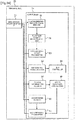
- Figure 1 is a flow chart illustrating operations of a handover performed by a radio communication system according to a first embodiment. Configurations of the radio communication system and a base station will now be described before presenting a description of a handover operation.
- FIG. 2 is a diagram illustrating an overall configuration of a radio communication system 1.
- the radio communication system 1 comprises a base station 10 of a macro cell C1, base stations 40 of a plurality of CSG cells C2 contained in the macro cell C1, and a terminal 70. Since a handover from a base station of the macro cell C1 to a base station of the CSG cell C2 will be described in the present embodiment, a base station 10 of the macro cell C1 shall be denoted as "SeNB 10" and base stations 40 of the CSG cell C2 as "TeNB 40". Note that the macro cell C1 corresponds to the "first cell” and the CSG cell C2 to the "second cell” as respectively set forth in the claims.
- the CSG cell C2 is given a cell ID. Although a cell ID is an identifier of the cell, there may be cases where cells having the same ID exist in the macro cell C1.
- the CSG cell C2 has a TAID as access information.
- the base station of the CSG cell C2 permits access from a terminal 70 having the same TAID.
- FIG 3 is a diagram illustrating a configuration of the base station (SeNB) 10 that is a handover source.
- the SeNB 10 comprises a base station communication interface (eNB Communication IF) 12 that is a communication interface with the TeNB 40 of the CSG cell C2, a terminal communication interface (UE Communication IF) 14 that is a communication interface with the terminal 70, a NCL 16 storing information on neighbor cells, and a controller 18 that controls communication with the TeNB 40 and the terminal 70.
- the NCL 16 contains cell IDs, access information (TAID), and the like of base stations neighboring the SeNB.
- the controller 18 comprises a measurement report receiver 20, a handover judging unit 22, a handover request transmitter 24, a handover response receiver 26, and an identifier transmitter 28.
- Figure 3 illustrates a configuration necessary for performing a handover
- the SeNB 10 has configurations necessary for communication control and the like in addition to the configuration described above.
- the measurement report receiver 20 receives a measurement report transmitted from the terminal 70.
- the measurement report contains a cell ID of a base station whose radio wave is detected by the terminal 70 and information on the reception quality of the radio wave.
- the handover judging unit 22 judges whether or not a handover should be performed based on the measurement report. For example, the handover judging unit 22 compares the reception qualities of the SeNB 10 and the TeNB 40, and judges that a handover to the TeNB 40 should be performed when the reception quality of the TeNB 40 is better than that of the SeNB 10.
- the handover request transmitter 24 transmits a handover request (HO request) to the base station of the handover destination.
- the handover request transmitter 24 determines a cell ID and a TAID of the CSG cell C2 using data in the NCL 16. Subsequently, the handover request transmitter 24 transmits a handover request to CSG cells C2 having the same TAID as the TAID of the terminal 70 that is the transmission source of the measurement report among the CSG cells C2 having the cell ID notified in the measurement report from the terminal 70.
- the handover response receiver 26 receives a handover response (HO response) transmitted from the TeNB 40 in response to the handover request.
- the identifier transmitter 28 transmits an identifier contained in the handover response to the terminal 70.
- FIG 4 is a diagram illustrating a configuration of the base station (TeNB) 40 that is the handover destination.
- the TeNB 40 comprises a base station communication interface (eNB Communication IF) 42 that is a communication interface with the SeNB 10 of the macro cell C1, a terminal communication interface (UE Communication IF) 44 that is a communication interface with the terminal 70, and a controller 46 that controls communication with the SeNB 10 and the terminal 70.
- eNB Communication IF base station communication interface
- UE Communication IF terminal communication interface
- the controller 46 comprises a handover request receiver 48, a handover enabled/disabled state judging unit 50, a handover response transmitter 52, a dedicated signal transmitter 54, and a RACH preamble receiver 56.
- Figure 4 illustrates a configuration necessary for performing a handover
- the TeNB 40 has configurations necessary for communication control and the like in addition to the configuration described above.
- the handover request receiver 48 receives a handover request transmitted from the SeNB 10.
- the handover enabled/disabled state judging unit 50 judges whether a handover is enabled or disabled based on whether there are new resources that can be allocated to the terminal 70, and the like.
- the handover response transmitter 52 transmits a handover response in response to the handover request.
- the handover response contains an identifier to be used by the TeNB 40 to identify the terminal 70 in the second cell.
- the dedicated signal transmitter 54 transmits a dedicated signal containing a handover command to the terminal 70 using a dedicated channel.
- the RACH preamble receiver 56 receives a RACH preamble transmitted from the terminal 70.
- Figure 1 illustrates operations during a handover of the terminal 70, in communication with the SeNB 10, to the TeNB 40.
- the terminal 70 periodically transmits a measurement report to the SeNB 10 (S2).
- the SeNB 10 compares the reception quality of a radio wave from the SeNB 10 with the reception quality of a radio wave from the TeNB 40 to judge whether or not a handover should be performed (S4). For example, when the reception quality of a radio wave from the TeNB 40 is better than the reception quality of a radio wave from the SeNB 10 by a predetermined threshold or more, the SeNB 10 judges that a handover should be performed.
- the SeNB 10 judges that a handover should not be performed. When it is judged that a handover should not be performed (NO in S4), the SeNB 10 awaits the reception of a next measurement report.
- the SeNB 10 When it is judged that a handover should be performed (YES in S4), the SeNB 10 extracts TeNBs 40 having an identifier corresponding to the cell ID notified in the measurement report from the NCL 16. Subsequently, the SeNB 10 determines a TeNB 40 having the same TAID as the TAID of the terminal 70 among the extracted TeNBs 40 of the CSG cell C2 (S6), and judges whether or not the TeNB is a base station of a CSG cell (S8). When the TeNB is a CSG cell (YES in S8), a handover request is transmitted to the determined TeNB 40 (S10). When the TeNB is not a CSG cell (NO in S8), a handover of the macro cell is performed.
- the TeNB 40 having received the handover request judges whether a handover can be performed or not (S12).
- the TeNB 40 transmits a handover response to the SeNB 10 (S14).
- Figure 1 depicts a case where a handover can be performed.
- the radio communication system 1 does not perform operations of step S14 and thereafter and terminates the flow.
- an identifier of the terminal 70 with respect to the TeNB 40 is to be included in the handover response.
- a C-RNTI is used as the identifier.
- the SeNB 10 Upon receiving the handover response from the TeNB 40 (S14), the SeNB 10 transmits the C-RNTI contained in the handover response to the terminal 70 (S16). By receiving the C-RNTI transmitted from the SeNB 10, the terminal 70 can now receive the dedicated signal addressed to the terminal 70 to be transmitted from the TeNB 40 via a dedicated channel.
- the TeNB 40 When it is judged in S12 that a handover can be performed, the TeNB 40 starts transmission of the dedicated signal to the terminal 70 via the dedicated channel (S18).
- the dedicated signal includes access information and information contained in a handover command such as information necessary for uplink synchronization.
- the TeNB 40 repeatedly transmits the dedicated signal until the terminal 70 receives the dedicated signal and a RACH preamble is transmitted to the TeNB 40 (S20).
- the interval of repetitive transmission of the dedicated signal from the TeNB 40 to the terminal 70 is to be set shorter than a gap period of the terminal 70.
- the terminal 70 judges whether the dedicated signal has been received or not (S22).
- the terminal 70 can receive the dedicated signal if the dedicated signal is transmitted during the gap period of the terminal 70.
- the terminal 70 confirms whether access to the TeNB 40 has been permitted or not.
- step S6 since the SeNB 10 only transmits a handover request to a TeNB 40 that can be accessed from the terminal 70, the terminal 70 has been permitted access to the TeNB 40 transmitting the dedicated signal. Therefore, a reception of the dedicated signal signifies that access to the TeNB 40 that is the transmission source of the dedicated signal has been permitted.
- a judgment of handover failure is made and transmitted to the SeNB (S24).
- "a certain period of time” signifies a period of time corresponding to an interval between gap periods.
- the terminal 70 Upon receiving the dedicated signal, the terminal 70 starts processing for a handover based on the handover command contained in the dedicated signal. Specifically, the terminal 70 transmits a RACH preamble for starting uplink synchronization to the TeNB 40 (S26), and starts processing to connect to the TeNB 40. Upon receiving the RACH preamble, the TeNB 40 stops transmission of the dedicated signal (S28).
- a certain period of time signifies a period of time corresponding to an interval between gap periods.
- the TeNB 40 adopts a configuration that transmits a handover response containing a C-RNTI and causes the SeNB 10 to notify the C-RNTI to the terminal 70. Accordingly, a dedicated channel of the TeNB 40 can be allocated to the terminal 70 before receiving an handover command instruction and a handover process can be performed in a smooth manner.
- FIG. 5 is a diagram illustrating an example of a flow of signals transmitted and received during a handover by the radio communication system 1 according to the first embodiment.
- the TeNB 40 according to the first embodiment since the TeNB 40 according to the first embodiment repeatedly transmits the dedicated signal at a shorter interval than the gap period, at least one transmission of the individual will occur within a gap period. Therefore, the terminal 70 is able to reliably receive the dedicated signal during the first gap period and a handover can be performed in a short period of time.
- a radio communication system according to a second embodiment comprises a base station (SeNB) 10 of a macro cell C1, base stations (TeNBs) 40 of a plurality of CSG cells C2 contained in the macro cell C1, and a terminal 70.
- SeNB base station
- TeNBs base stations
- FIG. 6 is a diagram illustrating a configuration of the base station (SeNB) 10 that is a handover source.
- the SeNB 10 comprises a base station communication interface 12 that is a communication interface with the TeNB 40 of the CSG cell C2, a terminal communication interface 14 that is a communication interface with the terminal 70, a NCL 16 storing information on neighbor cells, and a controller 18 that controls communication with the TeNB 40 and the terminal 70.
- Figure 6 illustrates a configuration necessary for performing a handover
- the SeNB 10 has configurations necessary for communication control and the like in addition to the configuration described above.
- the controller 18 comprises a measurement report receiver 20, a handover judging unit 22, a handover request transmitter 24, a handover response receiver 26, an access permission judging unit 32, and a handover command transmitter 30.
- the measurement report receiver 20 receives a measurement report transmitted from the terminal 70.
- the measurement report contains a cell ID of a TeNB 40 whose radio wave is detected by the terminal 70 and information on the reception quality of the radio wave.
- the handover judging unit 22 judges whether or not a handover should be performed based on the measurement report.
- the handover request transmitter 24 transmits a handover request to the TeNB 40 of the handover destination.
- the handover request transmitter 24 determines a cell ID of a CSG cell using data in the NCL 16.
- the handover request transmitter 24 transmits the handover request to the TeNB 40 of the CSG cell C2 having the cell ID notified in the measurement report from the terminal 70.
- the handover response receiver 26 receives a handover response transmitted from the TeNB 40 in response to the handover request. Based on access information contained in the measurement report transmitted from the terminal 70, the access permission judging unit 32 judges whether or not access from the terminal 70 to the TeNB 40 that is the handover destination is permitted.
- the handover command transmitter 30 transmits a handover command to the terminal 70.
- FIG. 7 is a diagram illustrating a configuration of the base station (TeNB) 40 that is the handover destination.
- the TeNB 40 comprises a base station communication interface 42 that is a communication interface with the SeNB 10, a terminal communication interface 44 that is a communication interface with the terminal 70, and a controller 46 that controls communication with the SeNB 10 and the terminal 70.
- the controller 46 comprises a handover request receiver 48, a handover enabled/disabled state judging unit 50, a handover response transmitter 52, a system information transmitter 58, and a RACH preamble receiver 56.
- Figure 7 illustrates a configuration necessary for performing a handover
- the TeNB 40 has configurations necessary for communication control and the like in addition to the configuration described above.
- the handover request receiver 48 receives a handover request transmitted from the SeNB 10.
- the handover enabled/disabled state judging unit 50 judges whether a handover is enabled or disabled based on whether there are new resources that can be allocated to the terminal 70, and the like.
- the handover response transmitter 52 transmits a handover response in response to the handover request.
- the system information transmitter 58 transmits a system information (SU-1 signal) containing access information through a common channel. When it is judged that a handover can be performed with respect to a handover request received by the handover request receiver 48, the system information transmitter 58 reduces the transmission interval of the system information so as to be shorter than the gap period.
- the RACH preamble receiver 56 receives a RACH preamble transmitted from the terminal 70.
- FIG 8 is a flow chart illustrating operations during a handover by the radio communication system according to the second embodiment.
- the terminal 70 transmits a measurement report to the SeNB 10 currently engaged in communication (S30).
- the SeNB 10 compares the reception quality of a radio wave from the SeNB 10 with the reception quality of a radio wave from the TeNB 40 to judge whether or not a handover should be performed (S32). When it is judged that a handover should not be performed (NO in S32), the SeNB 10 awaits the reception of a next measurement report.
- the SeNB 10 When it is judged that a handover should be performed (YES in S32), the SeNB 10 extracts a TeNB 40 having an identifier corresponding to the cell ID notified in the measurement report from the NCL 16 (S34). Subsequently, when the TeNB is a CSG cell (YES in S36), the SeNB 10 transmits a handover request to the extracted TeNB 40 of the CSG cell C2 (S38). When the TeNB is not a CSG cell (NO in S36), a handover of the macro cell is performed.
- the TeNB 40 having received the handover request judges whether a handover can be performed or not (S40).
- the TeNB 40 transmits a handover response to the SeNB 10 (S42).
- a handover cannot be performed NO in S40
- the radio communication system does not perform operations of step S42 and thereafter and terminates the flow.
- the TeNB 40 sets the transmission interval of the SU-1 signal shorter than before receiving the handover request (S44), and repeatedly transmits the SU-1 signal (S46).
- the terminal 70 judges whether the SU-1 signal has been received or not (S48). If the SU-1 cannot be received over a certain period of time (NO in S48), a judgment of handover failure is made and transmitted to the SeNB (S50). In this case, "a certain period of time” signifies a period of time corresponding to an interval between gap periods.
- the terminal 70 can receive the SU-1 signal.
- the terminal 70 reads out a TAID of the TeNB 40 from the SU-1 signal.
- the terminal 70 compares the TAID of the TeNB 40 with its own TAID and judges whether access to the TeNB 40 is permitted or not.
- the terminal 70 transmits a measurement report containing an access permission judgment result to the SeNB 10 (S52).
- the SeNB 10 Upon receiving the measurement report from the terminal 70, the SeNB 10 judges whether access to the TeNB 40 is permitted or not based on the measurement report. When access by the terminal 70 is permitted, the SeNB 10 transmits a handover command to the terminal 70 (S54). Upon receiving the handover command, the terminal 70 starts processing for a handover. Specifically, the terminal 70 transmits a RACH preamble for starting uplink synchronization to the TeNB 40 (S56), and starts processing to connect to the TeNB 40. Upon receiving the RACH preamble, the TeNB 40 restores the transmission interval of the SU-1 signal to the interval prior to the start of handover processing (S58). This concludes the description of the radio communication system according to the second embodiment.
- the TeNB 40 according to the second embodiment adopts a configuration that shortens the transmission interval of an SU-1 signal to be transmitted to the terminal 70 as compared to before receiving a handover request when it is judged that a handover can be performed. Therefore, the terminal 70 is able to reliably receive the SU-1 signal containing access information transmitted from the TeNB 40 during a first gap period after shortening the transmission interval.
- Figures 9 and 10 are diagrams illustrating an example of a flow of signals transmitted and received during a handover by the radio communication system according to the second embodiment.
- Figure 9 illustrates a flow of signals when the terminal 70 approaches a TeNB 40 to which access is permitted.
- Figure 10 illustrates a flow of signals when the terminal 70 approaches a TeNB 40 to which access is not permitted.
- the terminal 70 can receive the SU-1 signal transmitted from the access-permitted TeNB 40 during a first gap period after shortening the transmission interval of the SU-1 signal. Accordingly, a handover can be performed in a short period of time.
- the terminal 70 since an SU-1 signal is also transmitted from a TeNB 40 to which access from the terminal 70 is not permitted at an interval shorter than the gap period, the terminal 70 is able to know that access to the TeNB 40 is not permitted upon receiving the SU-1 signal based on access information included in the SU-1 signal.
- the terminal 70 does not transmit a RACH preamble to a TeNB 40 to which access is not permitted.
- the terminal 70 does not transmit a RACH preamble to a TeNB 40 to which access is permitted when the terminal 70 is remote from the TeNB 40.
- the TeNB 40 may use a timer as a trigger to restore the transmission interval of the SU-1 signal to its original interval.
- the TeNB 40 performs processing for restoring the original transmission interval of the SU-1 signal upon the lapse of a certain period of time after the transmission interval of the SU-1 signal is shortened.
- "a certain period of time” signifies a period of time corresponding to an interval between gap periods.
- the transmission interval of the SU-1 signal after being once shortened may be longer than the gap period.
- FIG 11 is a flow chart illustrating operations during a handover by the radio communication system according to another aspect of the second embodiment.
- the terminal 70 transmits a measurement report to the SeNB 10 currently engaged in communication (S30).
- the SeNB 10 receives the measurement report, compares the reception quality of a radio wave from the SeNB 10 with the reception quality of a radio wave from the TeNB 40 to judge whether or not a handover should be performed (S32). When it is judged that a handover should not be performed (NO in S32), the SeNB 10 awaits the reception of a next measurement report.
- the SeNB 10 extracts a TeNB 40 having an identifier corresponding to the cell ID notified in the measurement report from the NCL 16 (S34). Subsequently, the SeNB judges whether or not the TeNB is a base station of a CSG cell (S36). When the TeNB is a CSG cell (YES in S36), the SeNB 10 transmits an SU-1 transmission frequency change instruction to the extracted TeNB 40 of the CSG cell C2 (S39). When the TeNB is not a CSG cell (NO in S36), a handover of the macro cell is performed.
- the TeNB 40 having received the SU-1 transmission frequency change instruction sets the transmission interval of the SU-1 signal shorter than before receiving the handover request (S44), and repeatedly transmits the SU-1 signal (S46).
- the terminal 70 judges whether the SU-1 signal has been received or not (S48). When the SU-1 signal is transmitted during a gap period, the terminal 70 can receive the SU-1 signal. When the SU-1 signal is judged to be received (YES in S48), the terminal 70 reads out a TAID of the TeNB 40 from the SU-1 signal. The terminal 70 compares the TAID of the TeNB 40 with its own TAID and judges whether access to the TeNB 40 is permitted or not. The terminal 70 transmits a measurement report containing an access permission judgment result to the SeNB 10 (S52). If the SU-1 cannot be received over a certain period of time (NO in S48), a judgment of handover failure is made and transmitted to the SeNB 10 (S50). In this case, "a certain period of time” signifies a period of time corresponding to an interval between gap periods.
- the SeNB 10 Upon receiving the measurement report from the terminal 70, the SeNB 10 judges whether access to the TeNB 40 is permitted or not based on the measurement report. When access by the terminal 70 is permitted, the SeNB 10 transmits a handover request to the TeNB 40 (S38). The TeNB 40 having received the handover request judges whether a handover can be performed or not (S40), and when a handover can be performed, the TeNB 40 transmits a handover response to the SeNB 10 (S42). Note that Figure 11 depicts a case where a handover can be performed. When a handover cannot be performed (NO in S40), the radio communication system does not perform operations of step S42 and thereafter and terminates the flow.
- the SeNB 10 Upon receiving the handover response from the TeNB 40, the SeNB 10 transmits a handover command to the terminal 70 (S54). Upon receiving the handover command, the terminal 70 starts processing for a handover. Specifically, the terminal 70 transmits a RACH preamble for starting uplink synchronization to the TeNB 40 (S56), and starts processing to connect to the TeNB 40. Upon receiving the RACH preamble, the TeNB 40 restores the transmission interval of the SU-1 signal to the interval prior to the start of handover processing (S58). This concludes the description about the operations during a handover by the radio communication system according to the other aspect of the second embodiment.
- the TeNB 40 adopts a configuration that shortens the transmission interval of an SU-1 signal to be transmitted to the terminal 70 as compared to before receiving a handover request when it is judged that a handover can be performed. Therefore, the terminal 70 is able to reliably receive the SU-1 signal containing access information transmitted from the TeNB 40 during a first gap period after shortening the transmission interval.
- Figures 12 and 13 are diagrams illustrating an example of a flow of signals transmitted and received during a handover by a radio communication system according to the other aspect of the second embodiment.
- Figure 12 illustrates a flow of signals when the terminal 70 approaches a TeNB 40 to which access is permitted
- Figure 13 illustrates a flow of signals when the terminal 70 approaches a TeNB 40 to which access is not permitted.
- the terminal 70 can receive a dedicated signal transmitted from the TeNB 40 to which access is permitted during a first gap period after the start of transmission of the dedicated signal. Accordingly, a handover can be performed in a short period of time.
- the terminal 70 since an SU-1 signal is also transmitted from a TeNB 40 to which access from the terminal 70 is not permitted at an interval shorter than the gap period, the terminal 70 is able to know that access to the TeNB 40 is not permitted upon receiving the SU-1 signal based on access information included in the SU-1 signal.
- the terminal 70 does not transmit a RACH preamble to a TeNB 40 to which access is not permitted. As similarly illustrated in Figure 13 , the terminal 70 does not transmit a RACH preamble to a TeNB 40 to which access is permitted when the terminal 70 is remote from the TeNB 40.
- the TeNB 40 may use a timer as a trigger to restore the transmission interval of the SU-1 signal to its original interval. In other words, the TeNB 40 performs processing for restoring the original transmission interval of the SU-1 signal upon the lapse of a certain period of time after the transmission interval of the SU-1 signal is shortened. In this case, "a certain period of time” signifies a period of time corresponding to an interval between gap periods.
- the transmission interval of the SU-1 signal after being once shortened may be longer than the gap period.
- a basic configuration of a base station according to the third embodiment is the same as the basic configuration of the base station according to the second embodiment (refer to Figures 6 and 7 ).
- an SeNB 10 according to the third embodiment differs from the SeNB 10 according to the second embodiment in that when judging that a handover should be performed, the SeNB 10 only transmits a handover request to a TeNB 40 permitting access by a terminal 70 that is a handover object.
- a handover request transmitter 24 determines a TeNB 40 with a TAID that is the same as the TAID of the terminal 70 having transmitted a measurement report based on an NCL 16, and transmits a handover request to the determined TeNB 40.
- Figure 14 is a flow chart illustrating operations during a handover by the radio communication system according to the third embodiment.
- Basic operations during a handover by the radio communication system according to the third embodiment are the same as the operations during a handover by the radio communication system according to the second embodiment.
- the following description will focus on the differences from the operations by the radio communication system according to the second embodiment.
- the SeNB 10 when the SeNB 10 judges that a handover should be performed (YES in S32), the SeNB 10 extracts TeNBs 40 corresponding to a cell ID notified in the measurement report from the NCL 16. Subsequently, the SeNB 10 determines a TeNB 40 having the same TAID as the TAID of the terminal 70 among the extracted TeNBs 40 (S35), and transmits a handover request to the determined TeNB 40 (S36).
- the operation by the TeNB 40 having received the handover request is the same as the second embodiment.
- a TeNB 40 not having received the handover request does not perform processing related to a handover and transmits an SU-1 signal at a regular interval.
- FIG. 15 is a diagram illustrating an example of a flow of signals transmitted and received during a handover by the radio communication system according to the third embodiment.
- the SeNB 10 transmits a handover request to a TeNB 40 to which access is permitted and does not transmit a handover request to a TeNB 40 to which access is not permitted. Therefore, a situation where a TeNB 40 not permitting access by the terminal 70 frequently transmits SU-1 signals can be prevented and wasteful use of resources to transmit the SU-1 signals can be avoided.
- the terminal 70 When the terminal 70 is approaching a CSG cell C2 to which access is not permitted and has distanced itself from a CSG cell C1 to which access is permitted, the terminal 70 is unable to receive an SU-1 signal.
- the terminal 70 does not receive an SU-1 signal for a certain period of time or, in other words, when an RACH preamble has not been transmitted even though a certain period of time has lapsed after shortening the transmission interval of the SU-1 signal, the TeNB 40 restores the transmission interval of the SU-1 signal to the original interval.
- Figure 16 is a flow chart illustrating operations during a handover by the radio communication system according to another aspect of the third embodiment.
- Basic operations during a handover by the radio communication system according to the third embodiment are the same as the operations during a handover by the radio communication system according to the second embodiment.
- the following description will focus on the differences from the operations by the radio communication system according to the second embodiment.
- the SeNB 10 when the SeNB 10 judges that a handover should be performed (YES in S32), the SeNB 10 extracts TeNBs 40 corresponding to a cell ID notified in the measurement report from the NCL 16. Subsequently, the SeNB 10 determines a TeNB 40 having the same TAID as the TAID of the terminal 70 among the extracted TeNBs 40 (S35), and transmits an SU-1 transmission frequency change instruction to the determined TeNB 40 (S39).
- the operation by the TeNB 40 having received the SU-1 transmission frequency change instruction is the same as the second embodiment (refer to Figure 11 ).
- a TeNB 40 not having received the SU-1 transmission frequency change instruction does not perform processing related to a handover and transmits an SU-1 signal at a regular interval.
- FIG 17 is a diagram illustrating an example of a flow of signals transmitted and received during a handover by a radio communication system according to the other aspect of the third embodiment.
- the SeNB 10 transmits an SU-1 transmission frequency change instruction to a TeNB 40 to which access is permitted and does not transmit a SU-1 transmission frequency change instruction to a TeNB 40 to which access is not permitted. Therefore, a situation where a TeNB 40 not permitting access by the terminal 70 frequently transmits SU-1 signals can be prevented and wasteful use of resources to transmit the SU-1 signals can be avoided.
- the terminal 70 When the terminal 70 is approaching a CSG cell C2 to which access is not permitted and has distanced itself from a CSG cell C1 to which access is permitted, the terminal 70 is unable to receive an SU-1 signal.
- the terminal 70 does not receive an SU-1 signal for a certain period of time or, in other words, when an RACH preamble has not been transmitted even though a certain period of time has lapsed after shortening the transmission interval of the SU-1 signal, the TeNB 40 restores the transmission interval of the SU-1 signal to the original interval.
- a basic configuration of a base station according to the fourth embodiment is the same as the basic configuration of the base station according to the third embodiment (refer to Figures 6 and 7 ).
- the fourth embodiment differs from the third embodiment in that after receiving a handover response, an SeNB 10 immediately transmits a handover command to a terminal 70.
- the handover command contains an instruction to have the terminal 70 receive an SU-1.
- the fourth embodiment also differs from the third embodiment in that the transmission frequency of an SU-1 signal is not changed. Accordingly, the terminal 70 having received a handover command starts receiving an SU-1 signal from the TeNB 40 after receiving the handover command. After receiving the SU-1 signal, the terminal 70 compares the TAID of the TeNB 40 with its own TAID and judges whether access to the TeNB 40 is permitted or not. When access is permitted, the terminal 70 transmits a RACH preamble to the TeNB 40, and if not, transmits a handover failure to an SeNB. Consequently, the period of time required by the handover can be reduced significantly when the terminal 70 is approaching a CSG cell to which access is permitted.
- FIG 18 is a flow chart illustrating operations during a handover by the radio communication system according to the fourth embodiment.
- the terminal 70 transmits a measurement report to the SeNB 10 currently engaged in communication (S30).
- the SeNB 10 compares the reception quality of a radio wave from the SeNB 10 with the reception quality of a radio wave from the TeNB 40 to judge whether or not a handover should be performed (S32). When it is judged that a handover should not be performed (NO in S32), the SeNB 10 awaits the reception of a next measurement report.
- the SeNB 10 extracts a TeNB 40 having an identifier corresponding to the cell ID notified in the measurement report from the NCL 16 (S34). Subsequently, the SeNB 10 judges whether or not the TeNB is a base station of a CSG cell (S36). When the TeNB is a CSG cell (YES in S36), the SeNB 10 transmits a handover request to the extracted TeNB 40 of the CSG cell C2 (S38). When the TeNB is not a CSG cell (NO in S36), a handover of the macro cell is performed.
- the TeNB 40 having received the handover request judges whether a handover can be performed or not (S40), and when a handover can be performed, the TeNB 40 transmits a handover response to the SeNB 10 (S42).
- a handover cannot be performed NO in S38
- the radio communication system does not perform operations of step S40 and thereafter and terminates the flow.
- the SeNB 10 Upon receiving the handover response, the SeNB 10 transmits a handover command to the terminal 70 (S54).
- the handover command contains an instruction to the terminal to receive an SU-1 signal.
- the terminal 70 starts reception processing for the SU-1 signal and receives the SU-1 signal. Since the terminal 70 can receive the SU-1 signal at a transmission frequency band of the TeNB 40 after receiving the handover command, a gap period need not be set to receive a signal from the TeNB 40. Therefore, the terminal 70 is capable of receiving the SU-1 signal from the TeNB by normal reception processing that does not involve providing a gap period.
- the terminal 70 reads out an TAID of the TeNB 40 from the SU-1 signal.
- the terminal 70 compares the TAID of the TeNB 40 with its own TAID and judges whether access to the TeNB 40 is permitted or not (S62). If access to the TeNB 40 has been permitted (YES in S62), a RACH preamble for starting uplink synchronization is transmitted to the TeNB 40 (S66). On the other hand, if access to the TeNB 40 is not permitted (NO in S64), a judgment of handover failure is made and transmitted to the SeNB 10 (S47). This concludes the description of the radio communication system according to the fourth embodiment.
- the terminal 70 since the terminal 70 switches reception frequency bands by having the SeNB 10 instruct the terminal 70 with a handover command to receive an SU-1 signal, the SU-1 signal can be received without using a gap period. Accordingly, the terminal 70 can now reliably perform access confirmation without having the TeNB 40 change the transmission interval of an SU-1 signal, thereby enabling a reduction in handover time.
- Figures 19 and 20 are diagrams illustrating an example of a flow of signals transmitted and received during a handover by the radio communication system according to the fourth embodiment.
- Figure 19 illustrates a flow of signals when the terminal 70 approaches a TeNB 40 to which access is permitted
- Figure 20 illustrates a flow of signals when the terminal 70 approaches a TeNB 40 to which access is not permitted.
- the terminal 70 can receive an SU-1 signal without using a gap period. Accordingly, a handover can be performed in a short period of time.
- the terminal 70 does not transmit a RACH preamble to a TeNB 40 to which access is not permitted. In addition, as similarly illustrated in Figure 20 , the terminal 70 also does not transmit a RACH preamble to a TeNB 40 to which access is permitted when the terminal 70 is remote from the TeNB 40.
- the present invention is not limited to the embodiments described above. While examples in which access information is notified to a terminal using a dedicated signal or an SU-1 signal have been described in the embodiments presented above, access information may also be notified to the terminal by other signals. In this case, the period to time required by a handover can be reduced by shortening a transmission interval of a signal for notifying access information as compared to before receiving a handover request or, preferably, by setting the transmission interval so as to be shorter than a gap period.
- a radio communication system according to the fifth embodiment reduces the period of time required by a handover by controlling the timing of a gap period of a terminal.
- FIG 23 is a diagram illustrating a configuration of a base station (SeNB) 10 that is a handover source.
- the SeNB 10 comprises a base station communication interface 12 that is a communication interface with a TeNB 40 of a CSG cell C2, a terminal communication interface 14 that is a communication interface with a terminal 70, a NCL 16 storing information on neighboring cells, and a controller 18 that controls communication with the TeNB 40 and the terminal 70.
- the NCL 16 contains cell IDs, access information (TAID), and the like of base stations neighboring the SeNB.
- the controller 18 comprises a measurement report receiver 20, a handover judging unit 22, a handover request transmitter 24, a handover response receiver 26, a handover command transmitter 30, a gap controller 34, and a gap control signal transmitter 36.
- Figure 23 illustrates a configuration necessary for performing a handover
- the SeNB 10 has configurations necessary for communication control and the like in addition to the configuration described above.
- the measurement report receiver 20, the handover judging unit 22, the handover request transmitter 24, the handover response receiver 26, and the handover command transmitter 30 have the same functions as the respective components comprising the SeNB 10 described with reference to Figure 6 .
- the gap controller 34 Based on a timing difference between a timing of a gap period included in a measurement report from the measurement report receiver 20 and a frame timing of the TeNB 40, the gap controller 34 delays the timing of the gap period of the terminal so as to coincide with a transmission timing of an SU-1 signal of the TeNB 40.
- the gap control signal transmitter 36 notifies the gap period timing newly set by the gap controller 34 to match the timings of gap periods of the base station 10 and the terminal 70.
- FIG 24 is a diagram illustrating a configuration of the terminal (UE) 70.
- the terminal 70 comprises a base station communication interface 72 that is a communication interface with the SeNB 10 of the macro cell C1 and the TeNB 40 of the CSG cell C2, and a controller 74 that controls communication with the SeNB 10 and the TeNB 40.
- the controller 74 comprises a synchronization signal/RS signal receiver 76, a reception quality measurement unit 78 that measures reception quality, and a measurement report transmitter 80 that transmits a measurement report to the base station.
- the controller 74 also comprises a gap control signal receiver 82 that receives a gap control signal and a gap controller 84 that controls a gap period timing based on the gap control signal.
- the controller 74 further comprises a system information receiver 86 that receives a system information, an access permission judging unit 88 that judges access permission based on the system information, a handover command receiver 90 that receives a handover command, and a RACH preamble transmitter 92 that transmits a RACH preamble upon starting communication with a base station.
- FIG. 25 is a flow chart illustrating operations during a handover by the radio communication system according to the fifth embodiment.
- the terminal 70 performs a cell search during a gap period and detects a transmission timing from the TeNB 40.
- the terminal 70 calculates a difference between the transmission timing from the TeNB 40 and the gap period timing, and transmits a measurement report combining the difference with a reception quality of the TeNB 40 to the SeNB 10 (S30).
- the SeNB 10 compares the reception quality of a radio wave from the SeNB 10 with the reception quality of a radio wave from the TeNB 40 to judge whether or not a handover should be performed (S32). When it is judged that a handover should not be performed (NO in S32), the SeNB 10 awaits the reception of a next measurement report.
- the SeNB 10 When it is judged that a handover should be performed (YES in S32), the SeNB 10 extracts a TeNB 40 having an identifier corresponding to the cell ID notified in the measurement report from the NCL 16 (S35). Subsequently, when the TeNB is a CSG cell (YES in S36), the SeNB 10 transmits a handover request to the extracted TeNB 40 of the CSG cell C2 (S38). When the TeNB is not a CSG cell (NO in S36), a handover of the macro cell is performed.
- the TeNB 40 having received the handover request judges whether a handover can be performed or not (S40).
- the TeNB 40 transmits a handover response to the SeNB 10 (S42).
- a handover cannot be performed NO in S40
- the radio communication system does not perform operations of step S42 and thereafter and terminates the flow.
- the SeNB 10 determines a changed value of the gap period timing such that a gap period of the terminal 70 matches a transmission timing of an SU-1 signal, and notifies the changed value of the gap period timing as gap control information to the terminal 70 (S70). Subsequently, the terminal 70 and the SeNB 10 simultaneously change gap period timings (S72, S74). The SeNB 10 transmits a handover command to the terminal 70 (S76).
- the terminal 70 detects an SU-1 signal at the changed gap period timing (S78) and confirms whether access is permitted (S80). When the terminal 70 judges that access is permitted (YES in S80), the terminal 70 transmits a RACH preamble for starting uplink synchronization to the TeNB 40 (S84), and starts processing to connect to the TeNB 40. When the terminal 70 judges that access is not permitted (NO in S80), the terminal 70 notifies a handover failure to the SeNB 10 (S82). This concludes the description of the radio communication system according to the fifth embodiment.
- Figures 26 and 27 are diagrams illustrating an example of a flow of signals transmitted and received during a handover by the radio communication system according to the fifth embodiment.
- Figure 26 illustrates a flow of signals when the terminal 70 approaches a TeNB 40 to which access is permitted
- Figure 27 illustrates a flow of signals when the terminal 70 approaches a TeNB 40 to which access is not permitted.
- a handover can be performed in a short period of time without having to shorten the transmission interval of a system information (SU-1 signal) by the TeNB 40 that is the base station of the handover destination CSG cell and without having to extend the gap period used by the terminal 70 to receive the system information.
- a system information SU-1 signal
- a system information of a base station includes an access-prohibited cell list (hereinafter referred to as "APCL") as a list of cells that prohibit access by a terminal.
- APCL access-prohibited cell list
- the APCL is notified to the terminal from a core network via the base station. A terminal having received the APCL cannot be handed over to a cell included in the list.
- system 1 a system where CSG cells and macro cells use different frequencies
- system 2 a terminal is able to distinguish between a CSG cell and a macro cell solely by differences in frequency.
- system 2 a system is conceivable in which a CSG cell can be distinguished from a macro cell by cell IDs instead of frequencies.
- a terminal is able to distinguish between a CSG cell and a macro cell by cell IDs.
- a cell ID list of neighboring CSG cells is defined as a CSG cell list and notified in the form of a system information to the terminal from a core network via the base station
- a terminal used in the system 1 that is an existing system must be usable in the system 2 that is a future network.
- the sixth embodiment provides a radio communication system designed to prevent wasting of communication resources when a terminal of the system 1 is used in the system 2.
- FIG. 28 is a diagram illustrating a configuration of a base station (an SeNB and a TeNB will be collectively referred to as an eNB) 100.
- the eNB 100 comprises a core NW communication interface 102 that is a communication interface with a core network, a terminal communication interface 104 that is a communication interface with a terminal 120, and a controller 106 that controls communication with the core NW and the terminal 120.
- the controller 106 comprises an access-prohibited cell list receiver (hereinafter referred to as an "APCL receiver”) 108, a CSG cell list receiver 110, a new access-prohibited cell list generator (hereinafter referred to as an "new APCL generator”) 112, and a system information transmitter 114.
- APCL receiver access-prohibited cell list receiver
- CSG cell list receiver CSG cell list receiver
- new APCL generator new access-prohibited cell list generator
- the APCL receiver 108 receives an APCL from the core network and transmits the APCL to the new APCL generator 112.
- the CSG cell list receiver 110 receives a CSL cell list from the core network and transmits the CSL cell list to the new APCL generator 112.
- Figure 29A is a diagram illustrating an example of an APCL
- Figure 29B is a diagram illustrating a CSG cell list.
- An APCL is a list of cell IDs identifying cells that do not permit access.
- a CSG cell list is a list indicating a range of cell IDs usable to identify a CSG cell.
- cell IDs 300 to 350 and 450 to 500 are used as CSG cell IDs.
- a terminal of the system 2 can identify whether a cell identified by a cell ID is a macro cell or a CSG cell based on whether the cell ID is included in these ranges.
- the new APCL generator 112 loads an APCL from the APCL receiver 108 and a CSG cell list from the CSG cell list receiver 110 and generates a new APCL.
- the new APCL generator 112 generates a new APCL by extracting only neighboring CSG cells from the CSG cell list and adding the extracted CSG list to the APCL.
- Figure 30 is a diagram illustrating an example of a new APCL generated by the new APCL generator 112.
- a new APCL contains an APCL and a neighbor CSG cell list.
- whether a cell ID in a new APCL indicates an access-prohibited cell or a neighbor CSG cell is determined based on whether the cell ID is included in a cell ID range defined in the CSG cell list.
- Figure 31 is a diagram illustrating another example of a new APCL generated by the new APCL generator 112.
- the new APCL illustrated in Figure 31 has flags for distinguishing between CSG cells and an APCL.
- the system information transmitter 114 transmits the inputted new APCL as a system information to a terminal 120.
- Figure 32 is a diagram illustrating a configuration of the terminal (UE) 120.
- the terminal 120 comprises a base station communication interface 122 that is a communication interface with a base station and a controller 124 that controls communication with the base station.
- the controller 124 comprises a new access-prohibited cell list receiver (hereinafter referred to as a "new APCL receiver") 126, a CSG cell list receiver 128, and a cell list extractor 130.
- the new APCL receiver 126 receives a new APCL from a system information transmitted from the base station.
- the CSG cell list receiver 128 receives a CSG cell list from the system information transmitted from the base station.
- the cell list extractor 130 extracts an APCL and a neighbor CSG cell list. In this case, the APCL is extracted by excluding cells included in the CSG cell list from the new APCL.
- the neighbor CSG cell list is generated from the excluded CSG cells.
- Figure 31 when flags are introduced into a new APCL, an APCL and a neighbor CSG cell list can be extracted using the flags.
- Figure 28 illustrates a configuration necessary for APCL extraction
- the terminal 120 has configurations necessary for communication control and the like in addition to the configuration described above.
- Figure 33 is a flow chart illustrating operations of APCL extraction of the terminal 120 in the radio communication system according to the sixth embodiment.
- the core network 140 transmits an APCL and a CSG cell list to the base station (eNB) 100 (S90, S92).
- the base station 100 generates a new APCL from the APCL and the CSG cell list (S94).
- the base station 100 transmits the generated new APCL as a system information to the terminal 120 (S96).
- the terminal 120 extracts an APCL and a neighbor CSG cell list based on the new APCL transmitted as the system information (S98). Accordingly, based on the APCL and the neighbor CSG cell list, the terminal 120 can distinguish cells to which access is permitted from cells to which access is not permitted and perform appropriate radio communication processing.
- an entire new APCL may appear to indicate access-prohibited cells from the perspective of a terminal of the system 1 that is incapable of identifying CSG cells and macro cells by cell IDs (refer to Figures 30 and 31 ).
- a terminal of the system 1 can treat a new APCL as an ordinary APCL.
- the terminal of the system 1 can generally apply an access restriction to perform control so as not to access CSG cells that are highly likely to deny access from the terminal, thereby preventing wasting of communication resources.
- a terminal of the system 2 can extract an APCL and a neighbor CSG cell list from a new APCL, the terminal can perform appropriate radio communication processing using these lists.
- a terminal of the system 1 can operate without incident in the system 2, and a terminal of the system 2 can receive an APCL and a neighbor CSG cell list without incident.
- information for transmitting a new APCL is not limited to a system information and a new APCL may be transmitted in the form of other information.
- the present invention has an advantageous effect in that a handover can be performed in a short period of time and is useful for performing a handover to a cell with access restrictions such as from a macro cell to a CSG cell. Additional embodiments are summarized in the following clauses.
Abstract
Description
- This application is based upon and claims the benefit of priority from Japanese Patent Application No.
2008-023207, filed on Feb. 1, 2008 2008-118558, filed on Apr. 30, 2008 - The present invention relates to a handover technique, and particularly, to a technique for performing a handover by judging whether or not access by a terminal to a cell that is a handover destination is permitted or not.
- Techniques for performing a handover of a terminal engaged in communication between different cells have been conventionally known. For example, Section 10.1.2.1.1 of "3GPP TS 36.300 V8.3.0" prescribes a procedure of a handover between macro cells.
Figure 21 is a flow chart of a handover described in "3GPP TS 36.300 V8.3.0". Hereinafter, a conventional handover procedure will be described with reference toFigure 21 . - First, a terminal (UE: User Equipment) receives a signal from a neighboring base station and measures propagation path quality. The terminal notifies a measurement result to a currently-connected base station (Source eNB, hereinafter referred to as "SeNB") by means of a measurement report ("2. MEASUREMENT REPORTS" illustrated in
Figure 21 ). The measurement report includes a cell identifier (cell ID) of a base station having good propagation path quality as seen from the terminal, access information of the terminal (Tracking Area ID, hereinafter referred to as "TAID"), and the like. The SeNB determines a base station with a good propagation path status as a handover destination base station (Target eNB, hereinafter referred to as "TeNB") of the terminal. - The SeNB has a list of neighbor cells (Neighbor Cell List, hereinafter referred to as "NCL"). An NCL is a list of cell IDs of base stations neighboring the SeNB, access information (TAID), and the like. The SeNB uses the NCL to transmit a handover request signal ("4. HANDOVER REQUEST" illustrated in
Figure 21 ) to a base station (TeNB) corresponding to a cell ID notified by the measurement report. - Upon receiving the handover request signal, the TeNB determines whether or not a handover can be performed based on the status of remaining resources and the like. When the TeNB determines that a handover can be performed, the TeNB transmits a handover response signal ("6. HANDOVER REQUEST ACKNOWLEDGE" illustrated in
Figure 21 ) to the SeNB. - Upon receiving the handover response signal, the SeNB transmits a handover execution instruction signal ("7. HANDOVER COMMAND" illustrated in
Figure 21 ) to the terminal. The handover execution instruction includes information necessary for the terminal for subsequent uplink synchronization such as a terminal identification ID (C-RNTI) in the TeNB. - Upon receiving the handover execution instruction, the terminal transmits a Random Access Preamble to the handover destination base station (TeNB) and starts the uplink synchronization ("9. SYNCHRONIZATION" illustrated in
Figure 21 ). Upon receiving the Random Access Preamble, the TeNB performs an uplink allocation for the terminal and notifies allocation information to the terminal ("10. UL ALLOCATION + TA FOR UE" illustrated inFigure 21 ). When connection with the TeNB is successful, the terminal transmits a handover confirmation signal ("11. HANDOVER CONFIRM" illustrated inFigure 21 ) to the TeNB and notifies that handover processing by the terminal has been completed. This concludes a basic outline of handover processing between macro cells. - The 3GPP LTE project is evaluating installing an indoor base station (Home eNB) in a home to construct a CSG (Closed Subscriber Group) cell. A plurality of CSG cells are provided in a single macro cell. Unlike a base station of a macro cell, a base station of a CSG cell is subjected to access restriction as seen in a table in Section 6.3.1a.3 in "3GPP TS 36.311 V8.0.0". Therefore, a terminal is only able to connect to an access-permitted base station. Even if the terminal detects a base station with exceptional propagation path quality, the terminal is unable to connect to the base station without access permission.
- In order to confirm whether or not access to a base station of a CSG cell is permitted, the terminal must confirm a TAID contained in a Scheduling Unit (hereinafter referred to as "SU-1") that is a system information transmitted from the base station. The terminal collates its own TAID and the TAID of the base station, and if the two TAIDs match, determines that access to the base station is permitted.
- A signal transmitted from the base station of a CSG cell may sometimes be communicated over a different frequency from a signal transmitted from the base station of a macro cell. In this case, in order to receive an SU-1 transmitted from the base station and confirm whether or not access is permitted, the terminal must temporarily suspend communication with the base station of the macro cell. In the present specification, a period during which communication with the base station of the macro cell is temporarily suspended shall be referred to as a "gap period". Even during a gap period, the terminal is capable of detecting a radio wave from a cell being communicated over a different frequency band.
- Since a CSG cell has the characteristics described above, the terminal must conceivably receive an SU-1 transmitted from the handover destination during the gap period and determine whether or not access to the CSG cell that is the handover destination is permitted.
-
Figure 22 is a diagram illustrating, based on specifications currently being formulated, operations during a handover from a base station of a macro cell to a base station of a CSG cell. Note that the flow depicted inFigure 22 is a virtual flow that attempts to describe improvements in the flow currently being formulated in an easily comprehensible manner, and is not heretofore known. InFigure 22 , UE denotes a terminal, SeNB denotes a base station of a macro cell that is a handover source, and TeNB denotes a base station of a CSG cell that is a handover destination. The TeNB periodically transmits an SU-1 to the terminal. Due to time sharing that switches between a period where a signal transmitted from the SeNB is received and a period where a signal transmitted from the TeNB is received (gap period), the terminal receives signals from both base stations having different frequencies. - The terminal detects radio waves of the SeNB and the TeNB, and transmits a report on the reception qualities of the radio waves to the SeNB that is in communication with the terminal. The SeNB judges whether a handover should be performed or not based on the reception qualities of the SeNB and the TeNB. For example, the SeNB compares the reception qualities of the SeNB and the TeNB and judges that a handover to the TeNB should be performed when the reception quality of the TeNB is better than the reception quality of the SeNB. When a handover should be performed, a handover request is transmitted to the TeNB. Having received the handover request, the TeNB judges a handover enabled/disabled state based on whether there are resources for connecting a new terminal and the like, and transmits a handover response to the SeNB. In this case, let us assume that the TeNB sends a handover OK response.
- Next, based on the report from the terminal, the SeNB determines whether access from the terminal to the TeNB is permitted or not. More specifically, upon receiving the SU-1, the terminal detects a TAID in the SU-1, compares the terminal TAID with the SeNB TAID, and judges whether access is possible or not. The terminal includes access permission information in the measurement report and transmits the same to the SeNB. When access from the terminal to the base station is permitted, the SeNB transmits a handover command to the terminal. Upon receiving the handover command, the terminal transmits a RACH preamble to the SeNB and performs an operation to connect to the TeNB. The following operations have been omitted from
Figure 22 . - As illustrated in
Figure 22 , in order to judge whether or not access to an SeNB that is the handover destination is permitted, the terminal must receive an SU-1 transmitted from the SeNB. Unless an SU-1 is transmitted during a gap period, there will be no more opportunities to receive an SU-1 until the next gap period. In addition, there is no guarantee that an SU-1 will be transmitted at a timing that coincides with the next gap period. For example, according to the specifications currently being formulated, a gap period exists every several 10 ms and only has a length of 6 ms. Unless an SU-1 is transmitted during a 6-ms gap period, there will be no more opportunities to receive an SU-1 until the next gap period. In addition, there is no guarantee that an SU-1 will be transmitted at a timing that coincides with the next gap period. Therefore, a judgment of whether or not access is permitted may take time and may result in a time-consuming handover operation. - Accordingly, in consideration of the background described above, it is an object of the present invention to provide a base station and a radio communication system capable of promptly judging whether access is permitted or not and realizing a handover in a smooth manner.
- A radio communication system according to the present invention comprises a first base station that controls communication with a terminal in a first cell and a second base station that controls communication with a terminal in a second cell contained in the first cell, wherein: the first base station transmits a handover request for performing a handover of the terminal from the first cell to the second cell to the second base station; the second base station transmits a handover response that is a response to the handover request and which includes an identifier of the terminal in the second cell to the base station of the first cell; the first base station notifies the identifier contained in the handover response to the terminal; and the second base station repeatedly transmits a dedicated signal containing a handover command via a dedicated channel set using the identifier at an interval shorter than a period during which the terminal is able to receive data from the base station of the second cell.
- A radio communication system according to another aspect of the present invention comprises a first base station that controls communication with a terminal in a first cell and a second base station that controls communication with a terminal in a second cell contained in the first cell, wherein: the first base station transmits a handover request for performing a handover of the terminal from the first cell to the second cell to the second base station; the second base station transmits a handover response that is a response to the handover request to the base station of the first cell; and the second base station shortens a transmission interval of a system information containing access information to be transmitted through a common channel in comparison to before receiving the handover request when performing a handover in response to the handover request.
- As will be described below, the present invention also includes other aspects. As such, the disclosure of the present invention is intended to provide a part of the present invention and is not intended to limit the scope of the present invention as described and claimed herein.
-
-
Figure 1 is a diagram illustrating operations during a handover by a radio communication system according to a first embodiment; -
Figure 2 is a diagram illustrating an overall configuration of a radio communication system according to the first embodiment; -
Figure 3 is a diagram illustrating a configuration of an SeNB according to the first embodiment; -
Figure 4 is a diagram illustrating a configuration of a TeNB according to the first embodiment; -
Figure 5 is a diagram illustrating an example of a flow of signals transmitted and received during a handover according to the first embodiment; -
Figure 6 is a diagram illustrating a configuration of an SeNB according to a second embodiment; -
Figure 7 is a diagram illustrating a configuration of a TeNB according to the second embodiment; -
Figure 8 is a diagram illustrating operations during a handover according to the second embodiment; -
Figure 9 is a diagram illustrating an example of a flow of signals transmitted and received during a handover according to the second embodiment; -
Figure 10 is a diagram illustrating an example of a flow of signals transmitted and received during a handover according to the second embodiment; -
Figure 11 is a diagram illustrating operations during a handover according to another aspect of the second embodiment; -
Figure 12 is a diagram illustrating an example of a flow of signals transmitted and received during a handover according to another aspect of the second embodiment; -
Figure 13 is a diagram illustrating an example of a flow of signals transmitted and received during a handover according to another aspect of the second embodiment; -
Figure 14 is a diagram illustrating operations during a handover according to a third embodiment; -
Figure 15 is a diagram illustrating an example of a flow of signals transmitted and received during a handover according to the third embodiment; -
Figure 16 is a diagram illustrating operations during a handover according to another aspect of the third embodiment; -
Figure 17 is a diagram illustrating an example of a flow of signals transmitted and received during a handover according to another aspect of the third embodiment; -
Figure 18 is a diagram illustrating operations during a handover according to a fourth embodiment; -
Figure 19 is a diagram illustrating an example of a flow of signals transmitted and received during a handover according to the fourth embodiment; -
Figure 20 is a diagram illustrating an example of a flow of signals transmitted and received during a handover according to the fourth embodiment; -
Figure 21 is a flow chart of a handover described in "3GPP TS 36.300 V8.3.0"; -
Figure 22 is a virtual diagram illustrating operations during a handover from a base station of a macro cell to a base station of a CSG cell; -
Figure 23 is a diagram illustrating a configuration of an SeNB according to a fifth embodiment; -
Figure 24 is a diagram illustrating a configuration of a terminal according to the fifth embodiment; -
Figure 25 is a diagram illustrating operations during a handover according to the fifth embodiment; -
Figure 26 is a diagram illustrating an example of a flow of signals transmitted and received during a handover according to the fifth embodiment; -
Figure 27 is a diagram illustrating an example of a flow of signals transmitted and received during a handover according to the fifth embodiment; -
Figure 28 is a diagram illustrating a configuration of an eNB of asystem 2 according to a sixth embodiment; -
Figure 29A is a diagram illustrating an example of an access-prohibited cell list; -
Figure 29B is a diagram illustrating a CSG cell list; -
Figure 30 is a diagram illustrating an example of a new access-prohibited cell list; -
Figure 31 is a diagram illustrating another example of a new access-prohibited cell list; -
Figure 32 is a diagram illustrating a configuration of a UE of thesystem 2 according to the sixth embodiment; and -
Figure 33 is a diagram illustrating an operation for extracting an access-prohibited cell list performed by a UE of thesystem 2 according to the sixth embodiment. - Hereinafter, a detailed description of the present invention will be given. It is to be understood that the embodiments of the present invention described hereinafter are illustrative only and various modifications can be made thereon. As such, the specific configurations and functions disclosed below are not intended to limit the scope of the present invention.
- A base station according to an embodiment controls, in a network including a first cell and a second cell contained in the first cell, communication with a terminal in the second cell, the base station comprising: a handover request receiver that receives a handover request for performing a handover of the terminal from the first cell to the second cell from a base station of the first cell; a handover response transmitter that transmits a handover response that is a response to the handover request and which includes an identifier of the terminal in the second cell to the base station of the first cell, and causes the base station of the first cell to notify the identifier to the terminal; and a dedicated signal transmitter that repeatedly transmits a dedicated signal containing a handover command to the terminal via a dedicated channel set using the identifier at an interval shorter than a period during which the terminal is able to receive data from the base station of the second cell.
- As described above, the base station of the second cell transmits a handover response including an identifier in response to a handover request to the base station of the first cell, and causes the base station of the first cell to notify the identifier to the terminal. Accordingly, a dedicated signal can be transmitted to the terminal using a dedicated channel by merely performing a process of returning a handover response to the base station of the first cell. In addition, since a transmission interval of the dedicated signal is set shorter than a period during which the terminal is able to receive data from the base station of the second cell, the terminal is able to receive the dedicated signal during a first receivable period after the start of transmission of the dedicated signal and a handover can be performed in a short period of time.
- The base station may further comprise a RACH preamble command receiver that receives a RACH preamble command transmitted from the terminal in accordance with the dedicated signal, wherein the dedicated signal transmitter may stop transmission of the dedicated signal when the RACH preamble command is received or when a predetermined period of time has lapsed from the start of transmission of the dedicated signal.
- By stopping transmission of the dedicated signal when a predetermined period of time has lapsed as described above, in the event that a handover of the terminal to the second cell is not performed, the base station of the second cell can release resources of the dedicated channel at an appropriate timing.
- A base station according to another embodiment controls, in a network including a first cell and a second cell contained in the first cell, communication with a terminal in the second cell, the base station comprising: a handover request receiver that receives a handover request for performing a handover of the terminal from the first cell to the second cell from a base station of the first cell; a handover response transmitter that transmits a response to the handover request to the base station of the first cell; and a system information transmitter that transmits a system information containing access information through a common channel, wherein the system information transmitter shortens a transmission interval of the system information as compared to before receiving the handover request when performing a handover in accordance with the handover request.
- As described above, the base station of the second cell shortens a transmission interval of a system information as compared to before receiving a handover request when performing a handover in accordance with the handover request. Accordingly, the probability of the terminal failing to receive the system information can be lowered and a handover can be performed in a short period of time. Moreover, by setting the transmission interval of the system information shorter than a period during which data is receivable from the base station of the second cell, the system information can be received during a first receivable period.
- The base station may further comprise a RACH preamble command receiver that receives a RACH preamble command transmitted from the terminal in accordance with the dedicated signal, wherein the system information transmitter may restore the transmission interval of the system information to an original transmission interval when the RACH preamble command is received or when a predetermined period of time has lapsed after shortening the transmission interval of the system information.
- By stopping transmission of the dedicated signal when a predetermined period of time has lapsed as described above, the base station of the second cell can restore resources of the common channel to an original usage state.
- A base station according to another embodiment controls, in a network including a first cell and a second cell contained in the first cell, communication with a terminal in the first cell, the base station comprising: a measurement report receiver that receives, from the terminal, a measurement report including a cell identifier of the second cell whose radio wave has been detected by the terminal and quality information of the radio wave; a handover request transmitter that transmits a handover request to a base station to which access from the terminal is permitted among base stations of the second cell having a cell identifier judged to be a handover destination when it is judged, based on the measurement report, that a handover of the terminal from the first cell to the second cell should be performed; a handover response receiver that receives a handover response that is a response to the handover request and which includes an identifier of the terminal in the second cell from the second cell; and an identifier transmitter that notifies the identifier contained in the handover response to the terminal.
- By notifying the identifier included in a response to a handover request to the terminal, a dedicated signal can be transmitted using a dedicated channel from the base station of the second cell to the terminal.
- A base station according to another embodiment controls, in a network including a first cell and a second cell contained in the first cell, communication with a terminal in the first cell, the base station comprising: a measurement report receiver that receives, from the terminal, a measurement report including a cell identifier of the second cell whose radio wave has been detected by the terminal and quality information of the radio wave; a handover request transmitter that transmits a handover request to a base station of the second cell having a cell identifier judged to be a handover destination when it is judged, based on the measurement report, that a handover of the terminal from the first cell to the second cell should be performed; a handover response receiver that receives a handover response to the handover request from the second cell; an access permission state notification receiver that receives information on an access permission state of the second cell from the terminal; and a handover command transmitter that transmits a handover command to the terminal when access to the base station of the second cell is permitted.
- As described above, the base station of the first cell transmits a handover request to all base stations having a cell identifier judged to be a handover destination regardless of whether access from the terminal is permitted or not. Accordingly, the base station of the second cell can transmit information regarding access permission to the terminal. For example, by having the base station of the second cell transmit a system information containing access information at an interval that is shorter than an ordinary system information transmission interval, the terminal can promptly comprehend whether access to the base station of the second cell is permitted or not.
- In the base station described above, the handover request transmitter may transmit the handover request to a base station to which access from the terminal is permitted among base stations of the second cell having a cell identifier to which it is judged that a handover should be performed based on the measurement report.
- As described above, the base station of the first cell transmits a handover request to a base station accessible by the terminal among base stations of the second cell having a cell identifier judged to be a handover destination. Accordingly, since resources for transmitting a handover request can be saved and the number of base stations of the second cell receiving the handover request can be reduced, the processing load on base stations of the second cell can be alleviated.
- A base station according to another embodiment comprises: a receiver that receives a measurement report from a terminal; a judging unit that judges whether a handover of the terminal should be performed or not based on the received measurement report; and a transmitter that transmits, when it is judged that a handover of the terminal should be performed, an instruction for changing a transmission frequency of a system information to a base station device that is a handover destination.
- As described above, by shortening the transmission interval of a system information to be transmitted by the base station of the handover destination as compared to before the judgment to perform a handover is made, the probability of the terminal failing to receive the system information can be lowered and a handover can be performed in a short period of time. Moreover, by setting the transmission interval of the system information shorter than a period during which data is receivable from the base station of the second cell, the system information can be received during a first receivable period.
- The base station according to the present invention may further comprise a handover command transmitter that transmits a handover command including a reception instruction of a system information to be transmitted from a base station that is a handover destination to the terminal when a handover-permitted response is received from the base station that is the handover destination.
- Accordingly, the terminal may switch to processing for receiving a system information to be transmitted from the base station of the handover destination so as to reliably receive the system information.
- A radio communication system according to the present invention comprises a first base station that controls communication with a terminal in a first cell and a second base station that controls communication with a terminal in a second cell contained in the first cell, wherein: the first base station transmits a handover request for performing a handover of the terminal from the first cell to the second cell to the second base station; the second base station transmits a handover response that is a response to the handover request and which includes an identifier of the terminal in the second cell to the base station of the first cell; the first base station notifies the identifier contained in the handover response to the terminal; and the second base station repeatedly transmits a dedicated signal containing a handover command to the terminal via a dedicated channel set using the identifier at an interval shorter than a period during which the terminal is able to receive data from the base station of the second cell.
- As described above, since the first base station notifies an identifier of the terminal in the second cell to the terminal, the second base station can transmit a dedicated signal to the terminal using a dedicated channel by merely performing a process of returning a handover response to the base station of the first cell. In addition, since a transmission interval of a dedicated signal including a handover command is set shorter than a period during which data can be received from the base station of the second cell, the terminal is able to receive the dedicated signal during a first receivable period after the start of transmission of the dedicated signal and a handover can be performed in a short period of time.
- A radio communication system according to another embodiment comprises a first base station that controls communication with a terminal in a first cell and a second base station that controls communication with a terminal in a second cell contained in the first cell, wherein: the first base station transmits a handover request for performing a handover of the terminal from the first cell to the second cell to the second base station; the second base station transmits a handover response that is a response to the handover request to the base station of the first cell; and the second base station shortens a transmission interval of a system information containing access information to be transmitted through a common channel in comparison to before receiving the handover request when performing a handover in response to the handover request.
- As described above, when the second base station receives a handover request, by shortening the transmission interval of a system information to be transmitted as compared to before receiving the handover request, the probability of the terminal failing to receive the system information can be lowered and a handover can be performed in a short period of time. Moreover, by setting the transmission interval of the system information shorter than a period during which data is receivable from the base station of the second cell, the system information can be received during a first receivable period.
- A handover method according to the present invention is to be performed by a base station that controls, in a network including a first cell and a second cell contained in the first cell, communication with a terminal in the second cell, the handover method comprising the steps of: receiving a handover request for performing a handover of the terminal from the first cell to the second cell from a base station of the first cell; transmitting a handover response that is a response to the handover request and which includes an identifier of the terminal in the second cell to the base station of the first cell, and causing the base station of the first cell to notify the identifier to the terminal; and repeatedly transmitting a dedicated signal containing a handover command to the terminal via a dedicated channel set using the identifier at an interval shorter than a period during which the terminal is able to receive data from the base station of the second cell.
- As described above, the base station of the second cell transmits a handover response including an identifier in response to a handover request and causes the base station of the first cell to notify the identifier to the terminal. Accordingly, the base station of the second cell can transmit a dedicated signal to the terminal using a dedicated channel by merely performing a process of returning a handover response to the base station of the first cell. In addition, since a transmission interval of the dedicated signal is set shorter than a period during which the terminal is able to receive data from the base station of the second cell, the terminal is able to receive the dedicated signal during a first receivable period after the start of transmission of the dedicated signal and a handover can be performed in a short period of time.
- A handover method according to another embodiment is to be performed by a base station that controls, in a network including a first cell and a second cell contained in the first cell, communication with a terminal in the second cell, the handover method comprising the steps of: receiving a handover request for performing a handover of the terminal from the first cell to the second cell from a base station of the first cell; transmitting a response to the handover request to the base station of the first cell; and shortening a transmission interval of a system information containing access information to be transmitted through a common channel in comparison to before receiving the handover request when performing a handover in response to the handover request.
- As described above, by shortening the transmission interval of a system information as compared to before receiving the handover request when a handover request is received, the probability of the terminal failing to receive the system information can be lowered and a handover can be performed in a short period of time. Moreover, by setting the transmission interval of the system information shorter than a period during which data is receivable from the base station of the second cell, the system information can be received during a first receivable period.
- Hereinafter, a radio communication system and a base station according to embodiments of the present invention will be described with reference to the drawings.
-
Figure 1 is a flow chart illustrating operations of a handover performed by a radio communication system according to a first embodiment. Configurations of the radio communication system and a base station will now be described before presenting a description of a handover operation. -
Figure 2 is a diagram illustrating an overall configuration of aradio communication system 1. Theradio communication system 1 comprises abase station 10 of a macro cell C1,base stations 40 of a plurality of CSG cells C2 contained in the macro cell C1, and a terminal 70. Since a handover from a base station of the macro cell C1 to a base station of the CSG cell C2 will be described in the present embodiment, abase station 10 of the macro cell C1 shall be denoted as "SeNB 10" andbase stations 40 of the CSG cell C2 as "TeNB 40". Note that the macro cell C1 corresponds to the "first cell" and the CSG cell C2 to the "second cell" as respectively set forth in the claims. - The CSG cell C2 is given a cell ID. Although a cell ID is an identifier of the cell, there may be cases where cells having the same ID exist in the macro cell C1. The CSG cell C2 has a TAID as access information. The base station of the CSG cell C2 permits access from a terminal 70 having the same TAID.
-
Figure 3 is a diagram illustrating a configuration of the base station (SeNB) 10 that is a handover source. TheSeNB 10 comprises a base station communication interface (eNB Communication IF) 12 that is a communication interface with theTeNB 40 of the CSG cell C2, a terminal communication interface (UE Communication IF) 14 that is a communication interface with the terminal 70, aNCL 16 storing information on neighbor cells, and acontroller 18 that controls communication with theTeNB 40 and the terminal 70. TheNCL 16 contains cell IDs, access information (TAID), and the like of base stations neighboring the SeNB. - The
controller 18 comprises ameasurement report receiver 20, ahandover judging unit 22, ahandover request transmitter 24, ahandover response receiver 26, and anidentifier transmitter 28. Moreover, whileFigure 3 illustrates a configuration necessary for performing a handover, theSeNB 10 has configurations necessary for communication control and the like in addition to the configuration described above. - The
measurement report receiver 20 receives a measurement report transmitted from the terminal 70. The measurement report contains a cell ID of a base station whose radio wave is detected by the terminal 70 and information on the reception quality of the radio wave. Thehandover judging unit 22 judges whether or not a handover should be performed based on the measurement report. For example, thehandover judging unit 22 compares the reception qualities of theSeNB 10 and theTeNB 40, and judges that a handover to theTeNB 40 should be performed when the reception quality of theTeNB 40 is better than that of theSeNB 10. When theHO judging unit 22 judges that a handover should be performed, thehandover request transmitter 24 transmits a handover request (HO request) to the base station of the handover destination. Thehandover request transmitter 24 determines a cell ID and a TAID of the CSG cell C2 using data in theNCL 16. Subsequently, thehandover request transmitter 24 transmits a handover request to CSG cells C2 having the same TAID as the TAID of the terminal 70 that is the transmission source of the measurement report among the CSG cells C2 having the cell ID notified in the measurement report from the terminal 70. Thehandover response receiver 26 receives a handover response (HO response) transmitted from theTeNB 40 in response to the handover request. Theidentifier transmitter 28 transmits an identifier contained in the handover response to the terminal 70. -
Figure 4 is a diagram illustrating a configuration of the base station (TeNB) 40 that is the handover destination. TheTeNB 40 comprises a base station communication interface (eNB Communication IF) 42 that is a communication interface with theSeNB 10 of the macro cell C1, a terminal communication interface (UE Communication IF) 44 that is a communication interface with the terminal 70, and acontroller 46 that controls communication with theSeNB 10 and the terminal 70. - The
controller 46 comprises ahandover request receiver 48, a handover enabled/disabledstate judging unit 50, ahandover response transmitter 52, adedicated signal transmitter 54, and aRACH preamble receiver 56. Moreover, whileFigure 4 illustrates a configuration necessary for performing a handover, theTeNB 40 has configurations necessary for communication control and the like in addition to the configuration described above. - The
handover request receiver 48 receives a handover request transmitted from theSeNB 10. The handover enabled/disabledstate judging unit 50 judges whether a handover is enabled or disabled based on whether there are new resources that can be allocated to the terminal 70, and the like. Thehandover response transmitter 52 transmits a handover response in response to the handover request. In this case, the handover response contains an identifier to be used by theTeNB 40 to identify the terminal 70 in the second cell. When it is judged that a handover can be performed, thededicated signal transmitter 54 transmits a dedicated signal containing a handover command to the terminal 70 using a dedicated channel. TheRACH preamble receiver 56 receives a RACH preamble transmitted from the terminal 70. - Next, operations of the
radio communication system 1 according to the first embodiment will be described with reference toFigure 1. Figure 1 illustrates operations during a handover of the terminal 70, in communication with theSeNB 10, to theTeNB 40. The terminal 70 periodically transmits a measurement report to the SeNB 10 (S2). TheSeNB 10 compares the reception quality of a radio wave from theSeNB 10 with the reception quality of a radio wave from theTeNB 40 to judge whether or not a handover should be performed (S4). For example, when the reception quality of a radio wave from theTeNB 40 is better than the reception quality of a radio wave from theSeNB 10 by a predetermined threshold or more, theSeNB 10 judges that a handover should be performed. When the reception quality of the radio wave from theSeNB 10 is better than that of theTeNB 40, theSeNB 10 judges that a handover should not be performed. When it is judged that a handover should not be performed (NO in S4), theSeNB 10 awaits the reception of a next measurement report. - When it is judged that a handover should be performed (YES in S4), the
SeNB 10 extracts TeNBs 40 having an identifier corresponding to the cell ID notified in the measurement report from theNCL 16. Subsequently, theSeNB 10 determines aTeNB 40 having the same TAID as the TAID of the terminal 70 among the extractedTeNBs 40 of the CSG cell C2 (S6), and judges whether or not the TeNB is a base station of a CSG cell (S8). When the TeNB is a CSG cell (YES in S8), a handover request is transmitted to the determined TeNB 40 (S10). When the TeNB is not a CSG cell (NO in S8), a handover of the macro cell is performed. - The
TeNB 40 having received the handover request judges whether a handover can be performed or not (S12). When a handover can be performed (YES in S12), theTeNB 40 transmits a handover response to the SeNB 10 (S14). Note thatFigure 1 depicts a case where a handover can be performed. When a handover cannot be performed (NO in S12), theradio communication system 1 does not perform operations of step S14 and thereafter and terminates the flow. When a handover can be performed, an identifier of the terminal 70 with respect to theTeNB 40 is to be included in the handover response. In the present embodiment, a C-RNTI is used as the identifier. - Upon receiving the handover response from the TeNB 40 (S14), the
SeNB 10 transmits the C-RNTI contained in the handover response to the terminal 70 (S16). By receiving the C-RNTI transmitted from theSeNB 10, the terminal 70 can now receive the dedicated signal addressed to the terminal 70 to be transmitted from theTeNB 40 via a dedicated channel. - When it is judged in S12 that a handover can be performed, the
TeNB 40 starts transmission of the dedicated signal to the terminal 70 via the dedicated channel (S18). In this case, the dedicated signal includes access information and information contained in a handover command such as information necessary for uplink synchronization. TheTeNB 40 repeatedly transmits the dedicated signal until the terminal 70 receives the dedicated signal and a RACH preamble is transmitted to the TeNB 40 (S20). The interval of repetitive transmission of the dedicated signal from theTeNB 40 to the terminal 70 is to be set shorter than a gap period of the terminal 70. - The terminal 70 judges whether the dedicated signal has been received or not (S22). The terminal 70 can receive the dedicated signal if the dedicated signal is transmitted during the gap period of the terminal 70. Upon receiving the dedicated signal (YES in S22), the terminal 70 confirms whether access to the
TeNB 40 has been permitted or not. In the present embodiment, in step S6, since theSeNB 10 only transmits a handover request to aTeNB 40 that can be accessed from the terminal 70, the terminal 70 has been permitted access to theTeNB 40 transmitting the dedicated signal. Therefore, a reception of the dedicated signal signifies that access to theTeNB 40 that is the transmission source of the dedicated signal has been permitted. If unable to receive the dedicated signal over a certain period of time (NO in S22), a judgment of handover failure is made and transmitted to the SeNB (S24). In this case, "a certain period of time" signifies a period of time corresponding to an interval between gap periods. - Upon receiving the dedicated signal, the terminal 70 starts processing for a handover based on the handover command contained in the dedicated signal. Specifically, the terminal 70 transmits a RACH preamble for starting uplink synchronization to the TeNB 40 (S26), and starts processing to connect to the
TeNB 40. Upon receiving the RACH preamble, theTeNB 40 stops transmission of the dedicated signal (S28). - When the terminal 70 does not receive the dedicated signal over a certain period of time, the terminal 70 is conceivably approaching a CSG cell C2 to which access is not permitted. In this case, "a certain period of time" signifies a period of time corresponding to an interval between gap periods. When a certain period of time lapses from the start of transmission of the dedicated signal, the
TeNB 40 stops transmission of the dedicated signal. This concludes the description of theradio communication system 1 and thebase stations - The
TeNB 40 according to the first embodiment adopts a configuration that transmits a handover response containing a C-RNTI and causes theSeNB 10 to notify the C-RNTI to the terminal 70. Accordingly, a dedicated channel of theTeNB 40 can be allocated to the terminal 70 before receiving an handover command instruction and a handover process can be performed in a smooth manner. - Next, an advantageous effect gained by transmitting the dedicated signal at a transmission interval that is shorter than the gap period will be described.
Figure 5 is a diagram illustrating an example of a flow of signals transmitted and received during a handover by theradio communication system 1 according to the first embodiment. As illustrated inFigure 5 , since theTeNB 40 according to the first embodiment repeatedly transmits the dedicated signal at a shorter interval than the gap period, at least one transmission of the individual will occur within a gap period. Therefore, the terminal 70 is able to reliably receive the dedicated signal during the first gap period and a handover can be performed in a short period of time. - Next, a radio communication system according to a second embodiment will be described. In the same manner as the first embodiment, a radio communication system according to the second embodiment comprises a base station (SeNB) 10 of a macro cell C1, base stations (TeNBs) 40 of a plurality of CSG cells C2 contained in the macro cell C1, and a terminal 70.
-
Figure 6 is a diagram illustrating a configuration of the base station (SeNB) 10 that is a handover source. TheSeNB 10 comprises a basestation communication interface 12 that is a communication interface with theTeNB 40 of the CSG cell C2, aterminal communication interface 14 that is a communication interface with the terminal 70, aNCL 16 storing information on neighbor cells, and acontroller 18 that controls communication with theTeNB 40 and the terminal 70. Moreover, whileFigure 6 illustrates a configuration necessary for performing a handover, theSeNB 10 has configurations necessary for communication control and the like in addition to the configuration described above. - The
controller 18 comprises ameasurement report receiver 20, ahandover judging unit 22, ahandover request transmitter 24, ahandover response receiver 26, an accesspermission judging unit 32, and ahandover command transmitter 30. - The
measurement report receiver 20 receives a measurement report transmitted from the terminal 70. The measurement report contains a cell ID of aTeNB 40 whose radio wave is detected by the terminal 70 and information on the reception quality of the radio wave. Thehandover judging unit 22 judges whether or not a handover should be performed based on the measurement report. - When the
handover judging unit 22 judges that a handover should be performed, thehandover request transmitter 24 transmits a handover request to theTeNB 40 of the handover destination. Thehandover request transmitter 24 determines a cell ID of a CSG cell using data in theNCL 16. Thehandover request transmitter 24 transmits the handover request to theTeNB 40 of the CSG cell C2 having the cell ID notified in the measurement report from the terminal 70. - The
handover response receiver 26 receives a handover response transmitted from theTeNB 40 in response to the handover request. Based on access information contained in the measurement report transmitted from the terminal 70, the accesspermission judging unit 32 judges whether or not access from the terminal 70 to theTeNB 40 that is the handover destination is permitted. Thehandover command transmitter 30 transmits a handover command to the terminal 70. -
Figure 7 is a diagram illustrating a configuration of the base station (TeNB) 40 that is the handover destination. TheTeNB 40 comprises a basestation communication interface 42 that is a communication interface with theSeNB 10, aterminal communication interface 44 that is a communication interface with the terminal 70, and acontroller 46 that controls communication with theSeNB 10 and the terminal 70. - The
controller 46 comprises ahandover request receiver 48, a handover enabled/disabledstate judging unit 50, ahandover response transmitter 52, asystem information transmitter 58, and aRACH preamble receiver 56. Moreover, whileFigure 7 illustrates a configuration necessary for performing a handover, theTeNB 40 has configurations necessary for communication control and the like in addition to the configuration described above. - The
handover request receiver 48 receives a handover request transmitted from theSeNB 10. The handover enabled/disabledstate judging unit 50 judges whether a handover is enabled or disabled based on whether there are new resources that can be allocated to the terminal 70, and the like. Thehandover response transmitter 52 transmits a handover response in response to the handover request. Thesystem information transmitter 58 transmits a system information (SU-1 signal) containing access information through a common channel. When it is judged that a handover can be performed with respect to a handover request received by thehandover request receiver 48, thesystem information transmitter 58 reduces the transmission interval of the system information so as to be shorter than the gap period. TheRACH preamble receiver 56 receives a RACH preamble transmitted from the terminal 70. -
Figure 8 is a flow chart illustrating operations during a handover by the radio communication system according to the second embodiment. The terminal 70 transmits a measurement report to theSeNB 10 currently engaged in communication (S30). TheSeNB 10 compares the reception quality of a radio wave from theSeNB 10 with the reception quality of a radio wave from theTeNB 40 to judge whether or not a handover should be performed (S32). When it is judged that a handover should not be performed (NO in S32), theSeNB 10 awaits the reception of a next measurement report. - When it is judged that a handover should be performed (YES in S32), the
SeNB 10 extracts aTeNB 40 having an identifier corresponding to the cell ID notified in the measurement report from the NCL 16 (S34). Subsequently, when the TeNB is a CSG cell (YES in S36), theSeNB 10 transmits a handover request to the extractedTeNB 40 of the CSG cell C2 (S38). When the TeNB is not a CSG cell (NO in S36), a handover of the macro cell is performed. - The
TeNB 40 having received the handover request judges whether a handover can be performed or not (S40). When a handover can be performed (YES in S40), theTeNB 40 transmits a handover response to the SeNB 10 (S42). When a handover cannot be performed (NO in S40), the radio communication system does not perform operations of step S42 and thereafter and terminates the flow. When a handover can be performed, theTeNB 40 sets the transmission interval of the SU-1 signal shorter than before receiving the handover request (S44), and repeatedly transmits the SU-1 signal (S46). - The terminal 70 judges whether the SU-1 signal has been received or not (S48). If the SU-1 cannot be received over a certain period of time (NO in S48), a judgment of handover failure is made and transmitted to the SeNB (S50). In this case, "a certain period of time" signifies a period of time corresponding to an interval between gap periods. When the SU-1 signal is transmitted during a gap period, the terminal 70 can receive the SU-1 signal. When the SU-1 signal is judged to be received (YES in S48), the terminal 70 reads out a TAID of the
TeNB 40 from the SU-1 signal. The terminal 70 compares the TAID of theTeNB 40 with its own TAID and judges whether access to theTeNB 40 is permitted or not. The terminal 70 transmits a measurement report containing an access permission judgment result to the SeNB 10 (S52). - Upon receiving the measurement report from the terminal 70, the
SeNB 10 judges whether access to theTeNB 40 is permitted or not based on the measurement report. When access by the terminal 70 is permitted, theSeNB 10 transmits a handover command to the terminal 70 (S54). Upon receiving the handover command, the terminal 70 starts processing for a handover. Specifically, the terminal 70 transmits a RACH preamble for starting uplink synchronization to the TeNB 40 (S56), and starts processing to connect to theTeNB 40. Upon receiving the RACH preamble, theTeNB 40 restores the transmission interval of the SU-1 signal to the interval prior to the start of handover processing (S58). This concludes the description of the radio communication system according to the second embodiment. - The
TeNB 40 according to the second embodiment adopts a configuration that shortens the transmission interval of an SU-1 signal to be transmitted to the terminal 70 as compared to before receiving a handover request when it is judged that a handover can be performed. Therefore, the terminal 70 is able to reliably receive the SU-1 signal containing access information transmitted from theTeNB 40 during a first gap period after shortening the transmission interval. -
Figures 9 and10 are diagrams illustrating an example of a flow of signals transmitted and received during a handover by the radio communication system according to the second embodiment.Figure 9 illustrates a flow of signals when the terminal 70 approaches aTeNB 40 to which access is permitted.Figure 10 illustrates a flow of signals when the terminal 70 approaches aTeNB 40 to which access is not permitted. - As illustrated in
Figure 9 , since theTeNB 40 according to the second embodiment transmits the SU-1 signal at an interval that is shorter than the gap period after receiving the handover request and returning a handover response, the terminal 70 can receive the SU-1 signal transmitted from the access-permittedTeNB 40 during a first gap period after shortening the transmission interval of the SU-1 signal. Accordingly, a handover can be performed in a short period of time. - As illustrated in
Figure 10 , in the second embodiment, since an SU-1 signal is also transmitted from aTeNB 40 to which access from the terminal 70 is not permitted at an interval shorter than the gap period, the terminal 70 is able to know that access to theTeNB 40 is not permitted upon receiving the SU-1 signal based on access information included in the SU-1 signal. - As illustrated in
Figure 10 , the terminal 70 does not transmit a RACH preamble to aTeNB 40 to which access is not permitted. In addition, as similarly illustrated inFigure 10 , the terminal 70 does not transmit a RACH preamble to aTeNB 40 to which access is permitted when the terminal 70 is remote from theTeNB 40. TheTeNB 40 may use a timer as a trigger to restore the transmission interval of the SU-1 signal to its original interval. In other words, theTeNB 40 performs processing for restoring the original transmission interval of the SU-1 signal upon the lapse of a certain period of time after the transmission interval of the SU-1 signal is shortened. In this case, "a certain period of time" signifies a period of time corresponding to an interval between gap periods. - While an example in which the transmission interval of the SU-1 signal is shortened compared to the gap period has been described above in the present embodiment, the transmission interval of the SU-1 signal after being once shortened may be longer than the gap period. By shortening the transmission interval of the SU-1 signal than before receiving the handover request, an advantageous effect can be gained in that the probability of receiving the SU-1 signal can be increased as compared to before receiving the handover request. Such an aspect is also to be included in the present invention.
-
Figure 11 is a flow chart illustrating operations during a handover by the radio communication system according to another aspect of the second embodiment. The terminal 70 transmits a measurement report to theSeNB 10 currently engaged in communication (S30). TheSeNB 10 receives the measurement report, compares the reception quality of a radio wave from theSeNB 10 with the reception quality of a radio wave from theTeNB 40 to judge whether or not a handover should be performed (S32). When it is judged that a handover should not be performed (NO in S32), theSeNB 10 awaits the reception of a next measurement report. - When it is judged that a handover should be performed (YES in S32), the
SeNB 10 extracts aTeNB 40 having an identifier corresponding to the cell ID notified in the measurement report from the NCL 16 (S34). Subsequently, the SeNB judges whether or not the TeNB is a base station of a CSG cell (S36). When the TeNB is a CSG cell (YES in S36), theSeNB 10 transmits an SU-1 transmission frequency change instruction to the extractedTeNB 40 of the CSG cell C2 (S39). When the TeNB is not a CSG cell (NO in S36), a handover of the macro cell is performed. - The
TeNB 40 having received the SU-1 transmission frequency change instruction sets the transmission interval of the SU-1 signal shorter than before receiving the handover request (S44), and repeatedly transmits the SU-1 signal (S46). - The terminal 70 judges whether the SU-1 signal has been received or not (S48). When the SU-1 signal is transmitted during a gap period, the terminal 70 can receive the SU-1 signal. When the SU-1 signal is judged to be received (YES in S48), the terminal 70 reads out a TAID of the
TeNB 40 from the SU-1 signal. The terminal 70 compares the TAID of theTeNB 40 with its own TAID and judges whether access to theTeNB 40 is permitted or not. The terminal 70 transmits a measurement report containing an access permission judgment result to the SeNB 10 (S52). If the SU-1 cannot be received over a certain period of time (NO in S48), a judgment of handover failure is made and transmitted to the SeNB 10 (S50). In this case, "a certain period of time" signifies a period of time corresponding to an interval between gap periods. - Upon receiving the measurement report from the terminal 70, the
SeNB 10 judges whether access to theTeNB 40 is permitted or not based on the measurement report. When access by the terminal 70 is permitted, theSeNB 10 transmits a handover request to the TeNB 40 (S38). TheTeNB 40 having received the handover request judges whether a handover can be performed or not (S40), and when a handover can be performed, theTeNB 40 transmits a handover response to the SeNB 10 (S42). Note thatFigure 11 depicts a case where a handover can be performed. When a handover cannot be performed (NO in S40), the radio communication system does not perform operations of step S42 and thereafter and terminates the flow. Upon receiving the handover response from theTeNB 40, theSeNB 10 transmits a handover command to the terminal 70 (S54). Upon receiving the handover command, the terminal 70 starts processing for a handover. Specifically, the terminal 70 transmits a RACH preamble for starting uplink synchronization to the TeNB 40 (S56), and starts processing to connect to theTeNB 40. Upon receiving the RACH preamble, theTeNB 40 restores the transmission interval of the SU-1 signal to the interval prior to the start of handover processing (S58). This concludes the description about the operations during a handover by the radio communication system according to the other aspect of the second embodiment. - According to the other aspect of the second embodiment, the
TeNB 40 adopts a configuration that shortens the transmission interval of an SU-1 signal to be transmitted to the terminal 70 as compared to before receiving a handover request when it is judged that a handover can be performed. Therefore, the terminal 70 is able to reliably receive the SU-1 signal containing access information transmitted from theTeNB 40 during a first gap period after shortening the transmission interval. -
Figures 12 and13 are diagrams illustrating an example of a flow of signals transmitted and received during a handover by a radio communication system according to the other aspect of the second embodiment.Figure 12 illustrates a flow of signals when the terminal 70 approaches aTeNB 40 to which access is permitted, andFigure 13 illustrates a flow of signals when the terminal 70 approaches aTeNB 40 to which access is not permitted. - As illustrated in
Figure 12 , since theTeNB 40 according to the second embodiment transmits the SU-1 signal at an interval that is shorter than the gap period, the terminal 70 can receive a dedicated signal transmitted from theTeNB 40 to which access is permitted during a first gap period after the start of transmission of the dedicated signal. Accordingly, a handover can be performed in a short period of time. - As illustrated in
Figure 13 , in the second embodiment, since an SU-1 signal is also transmitted from aTeNB 40 to which access from the terminal 70 is not permitted at an interval shorter than the gap period, the terminal 70 is able to know that access to theTeNB 40 is not permitted upon receiving the SU-1 signal based on access information included in the SU-1 signal. - Moreover, as illustrated in
Figure 13 , the terminal 70 does not transmit a RACH preamble to aTeNB 40 to which access is not permitted. As similarly illustrated inFigure 13 , the terminal 70 does not transmit a RACH preamble to aTeNB 40 to which access is permitted when the terminal 70 is remote from theTeNB 40. TheTeNB 40 may use a timer as a trigger to restore the transmission interval of the SU-1 signal to its original interval. In other words, theTeNB 40 performs processing for restoring the original transmission interval of the SU-1 signal upon the lapse of a certain period of time after the transmission interval of the SU-1 signal is shortened. In this case, "a certain period of time" signifies a period of time corresponding to an interval between gap periods. - While an example in which the transmission interval of the SU-1 signal is shortened compared to the gap period has been described above in the present embodiment, the transmission interval of the SU-1 signal after being once shortened may be longer than the gap period. By shortening the transmission interval of the SU-1 signal as compared to before receiving the handover request, an advantageous effect can be gained in that the probability of receiving the SU-1 signal can be increased as compared to before receiving the handover request. Such an aspect is also to be included in the present invention.
- Next, a radio communication system and a base station according to a third embodiment of the present invention will be described. A basic configuration of a base station according to the third embodiment is the same as the basic configuration of the base station according to the second embodiment (refer to
Figures 6 and7 ). However, anSeNB 10 according to the third embodiment differs from theSeNB 10 according to the second embodiment in that when judging that a handover should be performed, theSeNB 10 only transmits a handover request to aTeNB 40 permitting access by a terminal 70 that is a handover object. In the third embodiment, ahandover request transmitter 24 determines aTeNB 40 with a TAID that is the same as the TAID of the terminal 70 having transmitted a measurement report based on anNCL 16, and transmits a handover request to the determinedTeNB 40. -
Figure 14 is a flow chart illustrating operations during a handover by the radio communication system according to the third embodiment. Basic operations during a handover by the radio communication system according to the third embodiment are the same as the operations during a handover by the radio communication system according to the second embodiment. The following description will focus on the differences from the operations by the radio communication system according to the second embodiment. - In the radio communication system according to the third embodiment, when the
SeNB 10 judges that a handover should be performed (YES in S32), theSeNB 10 extracts TeNBs 40 corresponding to a cell ID notified in the measurement report from theNCL 16. Subsequently, theSeNB 10 determines aTeNB 40 having the same TAID as the TAID of the terminal 70 among the extracted TeNBs 40 (S35), and transmits a handover request to the determined TeNB 40 (S36). - The operation by the
TeNB 40 having received the handover request is the same as the second embodiment. ATeNB 40 not having received the handover request does not perform processing related to a handover and transmits an SU-1 signal at a regular interval. -
Figure 15 is a diagram illustrating an example of a flow of signals transmitted and received during a handover by the radio communication system according to the third embodiment. As illustrated inFigure 15 , theSeNB 10 transmits a handover request to aTeNB 40 to which access is permitted and does not transmit a handover request to aTeNB 40 to which access is not permitted. Therefore, a situation where aTeNB 40 not permitting access by the terminal 70 frequently transmits SU-1 signals can be prevented and wasteful use of resources to transmit the SU-1 signals can be avoided. - When the terminal 70 is approaching a CSG cell C2 to which access is not permitted and has distanced itself from a CSG cell C1 to which access is permitted, the terminal 70 is unable to receive an SU-1 signal. When the terminal 70 does not receive an SU-1 signal for a certain period of time or, in other words, when an RACH preamble has not been transmitted even though a certain period of time has lapsed after shortening the transmission interval of the SU-1 signal, the
TeNB 40 restores the transmission interval of the SU-1 signal to the original interval. -
Figure 16 is a flow chart illustrating operations during a handover by the radio communication system according to another aspect of the third embodiment. Basic operations during a handover by the radio communication system according to the third embodiment are the same as the operations during a handover by the radio communication system according to the second embodiment. The following description will focus on the differences from the operations by the radio communication system according to the second embodiment. - With the radio communication system according to the third embodiment, when the
SeNB 10 judges that a handover should be performed (YES in S32), theSeNB 10 extracts TeNBs 40 corresponding to a cell ID notified in the measurement report from theNCL 16. Subsequently, theSeNB 10 determines aTeNB 40 having the same TAID as the TAID of the terminal 70 among the extracted TeNBs 40 (S35), and transmits an SU-1 transmission frequency change instruction to the determined TeNB 40 (S39). - The operation by the
TeNB 40 having received the SU-1 transmission frequency change instruction is the same as the second embodiment (refer toFigure 11 ). ATeNB 40 not having received the SU-1 transmission frequency change instruction does not perform processing related to a handover and transmits an SU-1 signal at a regular interval. -
Figure 17 is a diagram illustrating an example of a flow of signals transmitted and received during a handover by a radio communication system according to the other aspect of the third embodiment. As illustrated inFigure 17 , theSeNB 10 transmits an SU-1 transmission frequency change instruction to aTeNB 40 to which access is permitted and does not transmit a SU-1 transmission frequency change instruction to aTeNB 40 to which access is not permitted. Therefore, a situation where aTeNB 40 not permitting access by the terminal 70 frequently transmits SU-1 signals can be prevented and wasteful use of resources to transmit the SU-1 signals can be avoided. - When the terminal 70 is approaching a CSG cell C2 to which access is not permitted and has distanced itself from a CSG cell C1 to which access is permitted, the terminal 70 is unable to receive an SU-1 signal. When the terminal 70 does not receive an SU-1 signal for a certain period of time or, in other words, when an RACH preamble has not been transmitted even though a certain period of time has lapsed after shortening the transmission interval of the SU-1 signal, the
TeNB 40 restores the transmission interval of the SU-1 signal to the original interval. - Next, a radio communication system and a base station according to a fourth embodiment of the present invention will be described. A basic configuration of a base station according to the fourth embodiment is the same as the basic configuration of the base station according to the third embodiment (refer to
Figures 6 and7 ). However, the fourth embodiment differs from the third embodiment in that after receiving a handover response, anSeNB 10 immediately transmits a handover command to a terminal 70. In this case, the handover command contains an instruction to have the terminal 70 receive an SU-1. - The fourth embodiment also differs from the third embodiment in that the transmission frequency of an SU-1 signal is not changed. Accordingly, the terminal 70 having received a handover command starts receiving an SU-1 signal from the
TeNB 40 after receiving the handover command. After receiving the SU-1 signal, the terminal 70 compares the TAID of theTeNB 40 with its own TAID and judges whether access to theTeNB 40 is permitted or not. When access is permitted, the terminal 70 transmits a RACH preamble to theTeNB 40, and if not, transmits a handover failure to an SeNB. Consequently, the period of time required by the handover can be reduced significantly when the terminal 70 is approaching a CSG cell to which access is permitted. -
Figure 18 is a flow chart illustrating operations during a handover by the radio communication system according to the fourth embodiment. The terminal 70 transmits a measurement report to theSeNB 10 currently engaged in communication (S30). TheSeNB 10 compares the reception quality of a radio wave from theSeNB 10 with the reception quality of a radio wave from theTeNB 40 to judge whether or not a handover should be performed (S32). When it is judged that a handover should not be performed (NO in S32), theSeNB 10 awaits the reception of a next measurement report. - When it is judged that a handover should be performed (YES in S32), the
SeNB 10 extracts aTeNB 40 having an identifier corresponding to the cell ID notified in the measurement report from the NCL 16 (S34). Subsequently, theSeNB 10 judges whether or not the TeNB is a base station of a CSG cell (S36). When the TeNB is a CSG cell (YES in S36), theSeNB 10 transmits a handover request to the extractedTeNB 40 of the CSG cell C2 (S38). When the TeNB is not a CSG cell (NO in S36), a handover of the macro cell is performed. - The
TeNB 40 having received the handover request judges whether a handover can be performed or not (S40), and when a handover can be performed, theTeNB 40 transmits a handover response to the SeNB 10 (S42). When a handover cannot be performed (NO in S38), the radio communication system does not perform operations of step S40 and thereafter and terminates the flow. - Upon receiving the handover response, the
SeNB 10 transmits a handover command to the terminal 70 (S54). The handover command contains an instruction to the terminal to receive an SU-1 signal. Having received the handover command, the terminal 70 starts reception processing for the SU-1 signal and receives the SU-1 signal. Since the terminal 70 can receive the SU-1 signal at a transmission frequency band of theTeNB 40 after receiving the handover command, a gap period need not be set to receive a signal from theTeNB 40. Therefore, the terminal 70 is capable of receiving the SU-1 signal from the TeNB by normal reception processing that does not involve providing a gap period. The terminal 70 reads out an TAID of theTeNB 40 from the SU-1 signal. The terminal 70 compares the TAID of theTeNB 40 with its own TAID and judges whether access to theTeNB 40 is permitted or not (S62). If access to theTeNB 40 has been permitted (YES in S62), a RACH preamble for starting uplink synchronization is transmitted to the TeNB 40 (S66). On the other hand, if access to theTeNB 40 is not permitted (NO in S64), a judgment of handover failure is made and transmitted to the SeNB 10 (S47). This concludes the description of the radio communication system according to the fourth embodiment. - In the fourth embodiment, since the terminal 70 switches reception frequency bands by having the
SeNB 10 instruct the terminal 70 with a handover command to receive an SU-1 signal, the SU-1 signal can be received without using a gap period. Accordingly, the terminal 70 can now reliably perform access confirmation without having theTeNB 40 change the transmission interval of an SU-1 signal, thereby enabling a reduction in handover time. -
Figures 19 and20 are diagrams illustrating an example of a flow of signals transmitted and received during a handover by the radio communication system according to the fourth embodiment.Figure 19 illustrates a flow of signals when the terminal 70 approaches aTeNB 40 to which access is permitted, andFigure 20 illustrates a flow of signals when the terminal 70 approaches aTeNB 40 to which access is not permitted. - As illustrated in
Figure 19 , the terminal 70 according to the fourth embodiment can receive an SU-1 signal without using a gap period. Accordingly, a handover can be performed in a short period of time. - Moreover, as illustrated in
Figure 20 , the terminal 70 does not transmit a RACH preamble to aTeNB 40 to which access is not permitted. In addition, as similarly illustrated inFigure 20 , the terminal 70 also does not transmit a RACH preamble to aTeNB 40 to which access is permitted when the terminal 70 is remote from theTeNB 40. - While a detailed description of a base station, a radio communication system, and a handover method according to the present invention has been given by citing embodiments thereof, the present invention is not limited to the embodiments described above. While examples in which access information is notified to a terminal using a dedicated signal or an SU-1 signal have been described in the embodiments presented above, access information may also be notified to the terminal by other signals. In this case, the period to time required by a handover can be reduced by shortening a transmission interval of a signal for notifying access information as compared to before receiving a handover request or, preferably, by setting the transmission interval so as to be shorter than a gap period.
- Next, a radio communication system and a base station according to a fifth embodiment of the present invention will be described. A radio communication system according to the fifth embodiment reduces the period of time required by a handover by controlling the timing of a gap period of a terminal.
-
Figure 23 is a diagram illustrating a configuration of a base station (SeNB) 10 that is a handover source. TheSeNB 10 comprises a basestation communication interface 12 that is a communication interface with aTeNB 40 of a CSG cell C2, aterminal communication interface 14 that is a communication interface with a terminal 70, aNCL 16 storing information on neighboring cells, and acontroller 18 that controls communication with theTeNB 40 and the terminal 70. TheNCL 16 contains cell IDs, access information (TAID), and the like of base stations neighboring the SeNB. - The
controller 18 comprises ameasurement report receiver 20, ahandover judging unit 22, ahandover request transmitter 24, ahandover response receiver 26, ahandover command transmitter 30, agap controller 34, and a gapcontrol signal transmitter 36. Moreover, whileFigure 23 illustrates a configuration necessary for performing a handover, theSeNB 10 has configurations necessary for communication control and the like in addition to the configuration described above. - The
measurement report receiver 20, thehandover judging unit 22, thehandover request transmitter 24, thehandover response receiver 26, and thehandover command transmitter 30 have the same functions as the respective components comprising theSeNB 10 described with reference toFigure 6 . Based on a timing difference between a timing of a gap period included in a measurement report from themeasurement report receiver 20 and a frame timing of theTeNB 40, thegap controller 34 delays the timing of the gap period of the terminal so as to coincide with a transmission timing of an SU-1 signal of theTeNB 40. The gapcontrol signal transmitter 36 notifies the gap period timing newly set by thegap controller 34 to match the timings of gap periods of thebase station 10 and the terminal 70. -
Figure 24 is a diagram illustrating a configuration of the terminal (UE) 70. The terminal 70 comprises a basestation communication interface 72 that is a communication interface with theSeNB 10 of the macro cell C1 and theTeNB 40 of the CSG cell C2, and acontroller 74 that controls communication with theSeNB 10 and theTeNB 40. - The
controller 74 comprises a synchronization signal/RS signal receiver 76, a receptionquality measurement unit 78 that measures reception quality, and ameasurement report transmitter 80 that transmits a measurement report to the base station. Thecontroller 74 also comprises a gapcontrol signal receiver 82 that receives a gap control signal and agap controller 84 that controls a gap period timing based on the gap control signal. Thecontroller 74 further comprises asystem information receiver 86 that receives a system information, an accesspermission judging unit 88 that judges access permission based on the system information, ahandover command receiver 90 that receives a handover command, and aRACH preamble transmitter 92 that transmits a RACH preamble upon starting communication with a base station. -
Figure 25 is a flow chart illustrating operations during a handover by the radio communication system according to the fifth embodiment. The terminal 70 performs a cell search during a gap period and detects a transmission timing from theTeNB 40. The terminal 70 calculates a difference between the transmission timing from theTeNB 40 and the gap period timing, and transmits a measurement report combining the difference with a reception quality of theTeNB 40 to the SeNB 10 (S30). TheSeNB 10 compares the reception quality of a radio wave from theSeNB 10 with the reception quality of a radio wave from theTeNB 40 to judge whether or not a handover should be performed (S32). When it is judged that a handover should not be performed (NO in S32), theSeNB 10 awaits the reception of a next measurement report. - When it is judged that a handover should be performed (YES in S32), the
SeNB 10 extracts aTeNB 40 having an identifier corresponding to the cell ID notified in the measurement report from the NCL 16 (S35). Subsequently, when the TeNB is a CSG cell (YES in S36), theSeNB 10 transmits a handover request to the extractedTeNB 40 of the CSG cell C2 (S38). When the TeNB is not a CSG cell (NO in S36), a handover of the macro cell is performed. - The
TeNB 40 having received the handover request judges whether a handover can be performed or not (S40). When a handover can be performed (YES in S40), theTeNB 40 transmits a handover response to the SeNB 10 (S42). When a handover cannot be performed (NO in S40), the radio communication system does not perform operations of step S42 and thereafter and terminates the flow. - Having received the handover response, based on a timing difference between the transmission timing of the
TeNB 40 and the gap period timing notified in the measurement report, theSeNB 10 determines a changed value of the gap period timing such that a gap period of the terminal 70 matches a transmission timing of an SU-1 signal, and notifies the changed value of the gap period timing as gap control information to the terminal 70 (S70). Subsequently, the terminal 70 and theSeNB 10 simultaneously change gap period timings (S72, S74). TheSeNB 10 transmits a handover command to the terminal 70 (S76). - The terminal 70 detects an SU-1 signal at the changed gap period timing (S78) and confirms whether access is permitted (S80). When the terminal 70 judges that access is permitted (YES in S80), the terminal 70 transmits a RACH preamble for starting uplink synchronization to the TeNB 40 (S84), and starts processing to connect to the
TeNB 40. When the terminal 70 judges that access is not permitted (NO in S80), the terminal 70 notifies a handover failure to the SeNB 10 (S82). This concludes the description of the radio communication system according to the fifth embodiment. -
Figures 26 and27 are diagrams illustrating an example of a flow of signals transmitted and received during a handover by the radio communication system according to the fifth embodiment.Figure 26 illustrates a flow of signals when the terminal 70 approaches aTeNB 40 to which access is permitted, andFigure 27 illustrates a flow of signals when the terminal 70 approaches aTeNB 40 to which access is not permitted. - As illustrated in
Figure 26 , according to the fifth embodiment, a handover can be performed in a short period of time without having to shorten the transmission interval of a system information (SU-1 signal) by theTeNB 40 that is the base station of the handover destination CSG cell and without having to extend the gap period used by the terminal 70 to receive the system information. - First, a background of a radio communication system according to a sixth embodiment will be described. In addition to access information of cells contained in an SU-1 signal, a system information of a base station includes an access-prohibited cell list (hereinafter referred to as "APCL") as a list of cells that prohibit access by a terminal. The APCL is notified to the terminal from a core network via the base station. A terminal having received the APCL cannot be handed over to a cell included in the list.
- At present, a system where CSG cells and macro cells use different frequencies (hereunder, referred to as system 1) is being considered. In the
system 1, a terminal is able to distinguish between a CSG cell and a macro cell solely by differences in frequency. On the other hand, as a future system (hereunder, referred to as system 2), a system is conceivable in which a CSG cell can be distinguished from a macro cell by cell IDs instead of frequencies. In thesystem 2, a terminal is able to distinguish between a CSG cell and a macro cell by cell IDs. In thesystem 2, a cell ID list of neighboring CSG cells is defined as a CSG cell list and notified in the form of a system information to the terminal from a core network via the base station - If such a system should materialize, in order to maintain compatibility of system informations between systems, a terminal used in the
system 1 that is an existing system must be usable in thesystem 2 that is a future network. - As described above, since a terminal of the
system 1 is not capable of distinguishing between a CSG cell and a macro cell by cell IDs, there is a possibility that the terminal may erroneously judge a CSG cell of thesystem 2 to be a macro cell. Generally, since the number of CSG cells having access restrictions is significantly large, attempts to access a CSG cell often result in not being able to connect to the CSG cell due to access restrictions, causing wasting of communication resources. The sixth embodiment provides a radio communication system designed to prevent wasting of communication resources when a terminal of thesystem 1 is used in thesystem 2. - Next, a radio base station and a terminal according to the sixth embodiment will be described.
Figure 28 is a diagram illustrating a configuration of a base station (an SeNB and a TeNB will be collectively referred to as an eNB) 100. TheeNB 100 comprises a coreNW communication interface 102 that is a communication interface with a core network, aterminal communication interface 104 that is a communication interface with a terminal 120, and acontroller 106 that controls communication with the core NW and the terminal 120. - The
controller 106 comprises an access-prohibited cell list receiver (hereinafter referred to as an "APCL receiver") 108, a CSGcell list receiver 110, a new access-prohibited cell list generator (hereinafter referred to as an "new APCL generator") 112, and asystem information transmitter 114. Moreover, whileFigure 28 illustrates a configuration necessary for system information transmission, theeNB 100 has configurations necessary for communication control and the like in addition to the configuration described above. - The
APCL receiver 108 receives an APCL from the core network and transmits the APCL to thenew APCL generator 112. The CSGcell list receiver 110 receives a CSL cell list from the core network and transmits the CSL cell list to thenew APCL generator 112. -
Figure 29A is a diagram illustrating an example of an APCL, andFigure 29B is a diagram illustrating a CSG cell list. An APCL is a list of cell IDs identifying cells that do not permit access. A CSG cell list is a list indicating a range of cell IDs usable to identify a CSG cell. As illustrated inFigure 29B ,cell IDs 300 to 350 and 450 to 500 are used as CSG cell IDs. A terminal of thesystem 2 can identify whether a cell identified by a cell ID is a macro cell or a CSG cell based on whether the cell ID is included in these ranges. - The
new APCL generator 112 loads an APCL from theAPCL receiver 108 and a CSG cell list from the CSGcell list receiver 110 and generates a new APCL. Thenew APCL generator 112 generates a new APCL by extracting only neighboring CSG cells from the CSG cell list and adding the extracted CSG list to the APCL. -
Figure 30 is a diagram illustrating an example of a new APCL generated by thenew APCL generator 112. As illustrated inFigure 30 , a new APCL contains an APCL and a neighbor CSG cell list. In this example, whether a cell ID in a new APCL indicates an access-prohibited cell or a neighbor CSG cell is determined based on whether the cell ID is included in a cell ID range defined in the CSG cell list. -
Figure 31 is a diagram illustrating another example of a new APCL generated by thenew APCL generator 112. The new APCL illustrated inFigure 31 has flags for distinguishing between CSG cells and an APCL. - When a CSG cell list from the CSG
cell list receiver 110 and a new APCL from thenew APCL generator 112 are inputted, thesystem information transmitter 114 transmits the inputted new APCL as a system information to a terminal 120. -
Figure 32 is a diagram illustrating a configuration of the terminal (UE) 120. The terminal 120 comprises a basestation communication interface 122 that is a communication interface with a base station and acontroller 124 that controls communication with the base station. - The
controller 124 comprises a new access-prohibited cell list receiver (hereinafter referred to as a "new APCL receiver") 126, a CSGcell list receiver 128, and acell list extractor 130. Thenew APCL receiver 126 receives a new APCL from a system information transmitted from the base station. The CSGcell list receiver 128 receives a CSG cell list from the system information transmitted from the base station. Based on the inputted new APCL and CSG cell list, thecell list extractor 130 extracts an APCL and a neighbor CSG cell list. In this case, the APCL is extracted by excluding cells included in the CSG cell list from the new APCL. The neighbor CSG cell list is generated from the excluded CSG cells. - Moreover, as illustrated in
Figure 31 , when flags are introduced into a new APCL, an APCL and a neighbor CSG cell list can be extracted using the flags. Moreover, whileFigure 28 illustrates a configuration necessary for APCL extraction, the terminal 120 has configurations necessary for communication control and the like in addition to the configuration described above. -
Figure 33 is a flow chart illustrating operations of APCL extraction of the terminal 120 in the radio communication system according to the sixth embodiment. Thecore network 140 transmits an APCL and a CSG cell list to the base station (eNB) 100 (S90, S92). Thebase station 100 generates a new APCL from the APCL and the CSG cell list (S94). Thebase station 100 transmits the generated new APCL as a system information to the terminal 120 (S96). The terminal 120 extracts an APCL and a neighbor CSG cell list based on the new APCL transmitted as the system information (S98). Accordingly, based on the APCL and the neighbor CSG cell list, the terminal 120 can distinguish cells to which access is permitted from cells to which access is not permitted and perform appropriate radio communication processing. - In the sixth embodiment, since a new APCL that integrates an APCL and a neighbor CSG cell list is used, an entire new APCL may appear to indicate access-prohibited cells from the perspective of a terminal of the
system 1 that is incapable of identifying CSG cells and macro cells by cell IDs (refer toFigures 30 and31 ). In other words, a terminal of thesystem 1 can treat a new APCL as an ordinary APCL. Accordingly, since a neighbor CSG cell of thesystem 2 will also be determined as an access-prohibited cell, the terminal of thesystem 1 can generally apply an access restriction to perform control so as not to access CSG cells that are highly likely to deny access from the terminal, thereby preventing wasting of communication resources. - As described in the above embodiment, since a terminal of the
system 2 can extract an APCL and a neighbor CSG cell list from a new APCL, the terminal can perform appropriate radio communication processing using these lists. - From the above, with the sixth embodiment, a terminal of the
system 1 can operate without incident in thesystem 2, and a terminal of thesystem 2 can receive an APCL and a neighbor CSG cell list without incident. - While an example in which a new APCL is transmitted to the terminal 120 as a system information has been described in the present embodiment, information for transmitting a new APCL is not limited to a system information and a new APCL may be transmitted in the form of other information.
- While there has been described what is at present considered to be the preferred embodiments of the present invention, it will be understood that various modifications may be made therein, and it is intended to cover in the appended claims all such modifications as fall within the true spirit and scope of the present invention.
- As described above, the present invention has an advantageous effect in that a handover can be performed in a short period of time and is useful for performing a handover to a cell with access restrictions such as from a macro cell to a CSG cell.
Additional embodiments are summarized in the following clauses. - Clause 1: A base station that controls, in a network including a first cell and a second cell contained in the first cell, communication with a terminal in the second cell, the base station comprising:
- a handover request receiver that receives a handover request for performing a handover of the terminal from the first cell to the second cell from a base station of the first cell;
- a handover response transmitter that transmits a handover response that is a response to the handover request and which includes an identifier of the terminal in the second cell to the base station of the first cell, and causes the base station of the first cell to notify the identifier to the terminal; and
- a dedicated signal transmitter that repeatedly transmits a dedicated signal containing a handover command to the terminal via a dedicated channel set using the identifier at an interval shorter than a period during which the terminal is able to receive data from the base station of the second cell.
- Clause 2: The base station according to
clause 1, further comprising a RACH preamble command receiver that receives a RACH preamble command transmitted from the terminal in accordance with the dedicated signal, wherein
the dedicated signal transmitter stops transmission of the dedicated signal when the RACH preamble command is received or when a predetermined period of time has lapsed from the start of transmission of the dedicated signal. - Clause 3: A base station that controls, in a network including a first cell and a second cell contained in the first cell, communication with a terminal in the second cell, the base station comprising:
- a handover request receiver that receives a handover request for performing a handover of the terminal from the first cell to the second cell from a base station of the first cell;
- a handover response transmitter that transmits a response to the handover request to the base station of the first cell; and
- a system information transmitter that transmits a system information containing access information through a common channel, wherein
- the system information transmitter shortens a transmission interval of the system information as compared to before receiving the handover request when performing a handover in accordance with the handover request.
- Clause 4: The base station according to clause 3, further comprising
- a RACH preamble command receiver that receives a RACH preamble command transmitted from the terminal in accordance with the dedicated signal, wherein
- the system information transmitter restores the transmission interval of the system information to an original transmission interval when the RACH preamble command is received or when a predetermined period of time has lapsed after shortening the transmission interval of the system information.
- Clause 5: A base station that controls, in a network including a first cell and a second cell contained in the first cell, communication with a terminal in the first cell, the base station comprising:
- a measurement report receiver that receives, from the terminal, a measurement report including a cell identifier of the second cell whose radio wave has been detected by the terminal and quality information of the radio wave;
- a handover request transmitter that transmits a handover request to a base station to which access from the terminal is permitted among base stations of the second cell having a cell identifier judged to be a handover destination when it is judged, based on the measurement report, that a handover of the terminal from the first cell to the second cell should be performed;
- a handover response receiver that receives a handover response that is a response to the handover request and which includes an identifier of the terminal in the second cell from the second cell; and
- an identifier transmitter that notifies the identifier contained in the handover response to the terminal.
- Clause 6: A base station that controls, in a network including a first cell and a second cell contained in the first cell, communication with a terminal in the first cell, the base station comprising:
- a measurement report receiver that receives, from the terminal, a measurement report including a cell identifier of the second cell whose radio wave has been detected by the terminal and quality information of the radio wave;
- a handover request transmitter that transmits a handover request to a base station of the second cell having a cell identifier judged to be a handover destination when it is judged, based on the measurement report, that a handover of the terminal from the first cell to the second cell should be performed;
- a handover response receiver that receives a handover response to the handover request from the second cell;
- an access permission state notification receiver that receives information on an access permission state of the second cell from the terminal; and
- a handover command transmitter that transmits a handover command to the terminal when access to the base station of the second cell is permitted.
- Clause 7: The base station according to clause 6, wherein the handover request transmitter transmits the handover request to a base station to which access from the terminal is permitted among base stations of the second cell having a cell identifier to which it is judged that a handover should be performed based on the measurement report.
- Clause 8: A base station comprising:
- a receiver that receives a measurement report from a terminal;
- a judging unit that judges whether a handover of the terminal should be performed or not based on the received measurement report; and
- a transmitter that transmits, when it is judged that a handover of the terminal should be performed, an instruction for changing a transmission frequency of a system information to a base station device that is a handover destination.
- Clause 9: The base station according to clause 8, further comprising
a handover command transmitter that transmits a handover command including a reception instruction of a system information to be transmitted from a base station that is a handover destination to the terminal when a handover-permitted response is received from the base station that is the handover destination. - Clause 10: A radio communication system comprising a first base station that controls communication with a terminal in a first cell and a second base station that controls communication with a terminal in a second cell contained in the first cell, wherein:
- the first base station transmits a handover request for performing a handover of the terminal from the first cell to the second cell to the second base station;
- the second base station transmits a handover response that is a response to the handover request and which includes an identifier of the terminal in the second cell to the base station of the first cell;
- the first base station notifies the identifier contained in the handover response to the terminal; and
- the second base station repeatedly transmits a dedicated signal containing a handover command to the terminal via a dedicated channel set using the identifier at an interval shorter than a period during which the terminal is able to receive data from the base station of the second cell.
- Clause 11: A radio communication system comprising a first base station that controls communication with a terminal in a first cell and a second base station that controls communication with a terminal in a second cell contained in the first cell, wherein:
- the first base station transmits a handover request for performing a handover of the terminal from the first cell to the second cell to the second base station;
- the second base station transmits a handover response that is a response to the handover request to the base station of the first cell; and
- the second base station shortens a transmission interval of a system information containing access information to be transmitted through a common channel in comparison to before receiving the handover request when performing a handover in response to the handover request.
- Clause 12: A handover method to be performed by a base station that controls, in a network including a first cell and a second cell contained in the first cell, communication with a terminal in the second cell, the handover method comprising the steps of:
- receiving a handover request for performing a handover of the terminal from the first cell to the second cell from a base station of the first cell;
- transmitting a handover response that is a response to the handover request and which includes an identifier of the terminal in the second cell to the base station of the first cell, and causing the base station of the first cell to notify the identifier to the terminal; and
- repeatedly transmitting a dedicated signal containing a handover command to the terminal via a dedicated channel set using the identifier at an interval shorter than a period during which the terminal is able to receive data from the base station of the second cell.
- Clause 13: A handover method to be performed by a base station that controls, in a network including a first cell and a second cell contained in the first cell, communication with a terminal in the second cell, the handover method comprising the steps of:
- receiving a handover request for performing a handover of the terminal from the first cell to the second cell from a base station of the first cell;
- transmitting a handover response to the handover request to the base station of the first cell; and
- shortening a transmission interval of a system information containing access information to be transmitted through a common channel in comparison to before receiving the handover request when performing a handover in response to the handover request.
Claims (12)
- A first radio communication terminal which is used in a radio communication network including a macrocell which is a first cell and a CSG cell which is a second cell, wherein the first radio communication terminal has a mobility control function for moving to the second cell, the radio communication terminal comprising:a first cell list receiving unit that receives a first cell list used by a second radio communication terminal not having the mobility control function for moving to the second cell and used by the first radio communication terminal;a second cell list receiving unit that receives a second cell list that includes information about the second cell and is used by the first radio communication terminal; anda cell list controlling unit that judges a neighboring cell to be a measurement target of reception quality measurement on the basis of the first cell list acquired from the first cell list receiving unit and the second cell list acquired by the second cell list receiving unit.
- The radio communication terminal according to claim 1, comprising:an accessibility judging unit that judges, if a target cell which is a handover destination candidate is the second cell, whether the first radio communication terminal is able to access the target cell on the basis of notification information received from the target cell; anda reception quality measurement reporting unit that reports a judgment result of the accessibility judging unit and a measurement result of measuring reception quality of the neighboring cell to a base station.
- The radio communication terminal according to claim 1, wherein the second cell list includes information indicating a range of a cell ID of the second cell.
- A communication method implemented by a first radio communication terminal in a radio communication network including a macrocell which is a first cell and a CSG cell which is the second cell, wherein the first radio communication terminal has a mobility control function for moving to the second cell, the method comprising the steps of:receiving a first cell list used by a second radio communication terminal not having the mobility control function for moving to the second cell and used by the first radio communication terminal;receiving a second cell list that includes information about the second cell and is used by the first radio communication terminal; andjudging a neighboring cell to be a measurement target of reception quality measurement on the basis of the first cell list and the second cell list.
- The communication method according to claim 4, comprising the steps of:judging, if a target cell which is a handover destination candidate is the second cell, whether the first radio communication terminal is able to access the target cell on the basis of notification information received from the target cell; andreporting a result of the accessibility judgment and a measurement result of measuring reception quality of the neighboring cell to a base station.
- The communication method according to claim 4, wherein the second cell list includes information indicating a range of a cell ID of the second cell.
- A base station of a first cell in a radio communication network including a macrocell which is the first cell and a CSG cell which is a second cell, the base station comprising:a first cell list transmitting unit that transmits a first cell list used by a first radio communication terminal having a mobility control function to the second cell and a second radio communication terminal not having the mobility control function to the second cell;a second cell list transmitting unit that transmits a second cell list that includes information about the second cell and is used by the first radio communication terminal; anda measurement controlling unit that causes the first radio communication terminal to measure reception quality of a neighboring cell.
- The base station according to claim 7, comprising a reception quality measurement report receiving unit that receives a judgment result of the first radio communication terminal judging, if a target cell which is a candidate for a handover destination of the first radio communication terminal is the second cell, whether the first radio communication terminal is able to access the target cell on the basis of notification information received from the target cell and a measurement result of the first radio communication terminal measuring reception quality of the neighboring cell, from the first radio communication terminal.
- The base station according to claim 7, wherein the second cell list includes information indicating a range of a cell ID of the second cell.
- A communication method implemented by a base station of a first cell in a radio communication network including a macrocell which is a first cell and a CSG cell which is the second cell, the method comprising the steps of:transmitting a first cell list used by a first radio communication terminal having a mobility control function to the second cell and a second radio communication terminal not having the mobility control function to the second cell;transmitting a second cell list that includes information about the second cell and is used by the first radio communication terminal; andcausing the first radio communication terminal to measure reception quality of a neighboring cell.
- The communication method according to claim 10, comprising a step of receiving a judgment result of the first radio communication terminal judging, if a target cell which is a candidate for a handover destination of the first radio communication terminal is the second cell, whether the first radio communication terminal is able to access the target cell on the basis of notification information received from the target cell and a measurement result of the first radio communication terminal measuring reception quality of the neighboring cell, from the first radio communication terminal.
- The communication method according to claim 10, wherein the second cell list includes information indicating a range of a cell ID of the second cell.
Priority Applications (1)
| Application Number | Priority Date | Filing Date | Title |
|---|---|---|---|
| EP20153425.2A EP3661266A1 (en) | 2008-02-01 | 2008-12-09 | Radio communication apparatus and radio communication method based on an access prohibited cell list |
Applications Claiming Priority (4)
| Application Number | Priority Date | Filing Date | Title |
|---|---|---|---|
| JP2008023207 | 2008-02-01 | ||
| JP2008118558A JP5015856B2 (en) | 2008-02-01 | 2008-04-30 | Base station, radio communication system, and handover method |
| PCT/JP2008/003665 WO2009095970A1 (en) | 2008-02-01 | 2008-12-09 | Base station, radio communication system, and handover method |
| EP08871995.0A EP2249602B1 (en) | 2008-02-01 | 2008-12-09 | Base station, radio communication system, and handover method |
Related Parent Applications (2)
| Application Number | Title | Priority Date | Filing Date |
|---|---|---|---|
| EP08871995.0A Division EP2249602B1 (en) | 2008-02-01 | 2008-12-09 | Base station, radio communication system, and handover method |
| EP08871995.0A Division-Into EP2249602B1 (en) | 2008-02-01 | 2008-12-09 | Base station, radio communication system, and handover method |
Related Child Applications (2)
| Application Number | Title | Priority Date | Filing Date |
|---|---|---|---|
| EP20153425.2A Division-Into EP3661266A1 (en) | 2008-02-01 | 2008-12-09 | Radio communication apparatus and radio communication method based on an access prohibited cell list |
| EP20153425.2A Division EP3661266A1 (en) | 2008-02-01 | 2008-12-09 | Radio communication apparatus and radio communication method based on an access prohibited cell list |
Publications (2)
| Publication Number | Publication Date |
|---|---|
| EP3270629A1 true EP3270629A1 (en) | 2018-01-17 |
| EP3270629B1 EP3270629B1 (en) | 2020-03-04 |
Family
ID=40912341
Family Applications (3)
| Application Number | Title | Priority Date | Filing Date |
|---|---|---|---|
| EP20153425.2A Pending EP3661266A1 (en) | 2008-02-01 | 2008-12-09 | Radio communication apparatus and radio communication method based on an access prohibited cell list |
| EP17189591.5A Active EP3270629B1 (en) | 2008-02-01 | 2008-12-09 | Base station, radio communication system, and handover method based on access prohibited cell list |
| EP08871995.0A Active EP2249602B1 (en) | 2008-02-01 | 2008-12-09 | Base station, radio communication system, and handover method |
Family Applications Before (1)
| Application Number | Title | Priority Date | Filing Date |
|---|---|---|---|
| EP20153425.2A Pending EP3661266A1 (en) | 2008-02-01 | 2008-12-09 | Radio communication apparatus and radio communication method based on an access prohibited cell list |
Family Applications After (1)
| Application Number | Title | Priority Date | Filing Date |
|---|---|---|---|
| EP08871995.0A Active EP2249602B1 (en) | 2008-02-01 | 2008-12-09 | Base station, radio communication system, and handover method |
Country Status (5)
| Country | Link |
|---|---|
| US (10) | US8626173B2 (en) |
| EP (3) | EP3661266A1 (en) |
| JP (1) | JP5015856B2 (en) |
| CN (2) | CN104243081B (en) |
| WO (1) | WO2009095970A1 (en) |
Families Citing this family (48)
| Publication number | Priority date | Publication date | Assignee | Title |
|---|---|---|---|---|
| KR101493456B1 (en) * | 2007-11-28 | 2015-02-13 | 삼성전자주식회사 | Method for handover from home cell to public cell in mobile communication network |
| KR101157757B1 (en) | 2008-03-19 | 2012-06-25 | 샤프 가부시키가이샤 | Mobile communication system, base station device, mobile station device, and mobile communication method |
| KR20100070279A (en) * | 2008-12-17 | 2010-06-25 | 이용석 | Method for operating femto-cell in wireless communication system |
| KR101638842B1 (en) | 2009-02-13 | 2016-07-13 | 삼성전자주식회사 | Method and apparatus for handover at wireless communication network comprising femto cell |
| US8385291B2 (en) * | 2009-06-10 | 2013-02-26 | Airvana Llc | Mobility in a wireless enterprise network |
| US9166875B2 (en) * | 2009-06-22 | 2015-10-20 | Qualcomm Incorporated | Method and apparatus for network optimization using SON solutions |
| WO2011013178A1 (en) * | 2009-07-31 | 2011-02-03 | Panasonic Corporation | A method and apparatus for inbound handover preparation control in a mobile communications system |
| JP4648474B2 (en) * | 2009-08-18 | 2011-03-09 | 株式会社エヌ・ティ・ティ・ドコモ | Mobile communication method |
| JP2011041235A (en) * | 2009-08-18 | 2011-02-24 | Ntt Docomo Inc | Mobile communication method, radio base station, and gateway apparatus |
| US8599768B2 (en) * | 2009-08-24 | 2013-12-03 | Intel Corporation | Distributing group size indications to mobile stations |
| EP2496017A4 (en) * | 2009-10-26 | 2016-12-28 | Nec Corp | Mobile communication system, gateway apparatus, base stations, communication method and program |
| US8630642B2 (en) | 2009-10-30 | 2014-01-14 | Htc Corporation | Method of handling proximity information transmission and related communication device |
| US8391871B2 (en) * | 2009-10-30 | 2013-03-05 | Htc Corporation | Method of handling proximity information transmission and related communication device |
| JP4695213B1 (en) | 2009-11-02 | 2011-06-08 | 株式会社エヌ・ティ・ティ・ドコモ | Mobile communication method and mobile station |
| CN101729993B (en) * | 2010-01-05 | 2013-04-24 | 华为技术有限公司 | Access method, device and system |
| WO2011086934A1 (en) * | 2010-01-15 | 2011-07-21 | パナソニック株式会社 | Handover preprocessing system, mobile terminal, base station |
| JP5185969B2 (en) * | 2010-04-02 | 2013-04-17 | 株式会社エヌ・ティ・ティ・ドコモ | Mobile device and method in mobile communication system |
| KR20110111790A (en) * | 2010-04-05 | 2011-10-12 | 주식회사 팬택 | Method and apparatus for signaling component carrier information of handover in communication system using multiple component carrier |
| CN106211248B (en) * | 2010-04-28 | 2020-02-21 | 北京三星通信技术研究有限公司 | Method for processing base station in mobile communication system and corresponding base station |
| US9801102B2 (en) | 2010-04-28 | 2017-10-24 | Samsung Electronics Co., Ltd. | Method and apparatus for handover using X2 interface based on closed subscriber group in mobile communication system |
| US8600387B2 (en) * | 2010-04-29 | 2013-12-03 | Qualcomm Incorporated | Method and apparatus for performing intra closed subscriber group handover |
| WO2011136267A1 (en) * | 2010-04-30 | 2011-11-03 | 三菱電機株式会社 | Mobile unit communication system |
| US20120002637A1 (en) * | 2010-06-18 | 2012-01-05 | Interdigital Patent Holdings, Inc. | Method and apparatus for supporting home node-b mobility |
| US8934912B2 (en) * | 2010-11-08 | 2015-01-13 | Electronics And Telecommunications Research Institute | Method for deciding unregistered macrocell user equipment adjacent to femtocell base station |
| JP2012213061A (en) * | 2011-03-31 | 2012-11-01 | Jvc Kenwood Corp | Base station, mobile station, radio communication system, and control method for base station and mobile station |
| US9161253B2 (en) * | 2011-10-03 | 2015-10-13 | Mediatel Inc. | QoS verification and throughput measurement for minimization of drive test |
| CN103167574B (en) * | 2011-12-19 | 2015-11-25 | 华为技术有限公司 | Determine Timing Advance group technology and the equipment of Serving cell |
| WO2013111888A1 (en) * | 2012-01-27 | 2013-08-01 | 京セラ株式会社 | Communication control method, base station, and user terminal |
| EP3145243A1 (en) | 2012-07-18 | 2017-03-22 | NEC Corporation | Radio base station, mobile communication system, handover control method, and program |
| JP6042127B2 (en) | 2012-07-25 | 2016-12-14 | 株式会社Nttドコモ | Mobile terminal apparatus and base station apparatus |
| US9414288B2 (en) * | 2012-08-21 | 2016-08-09 | Kyocera Corporation | Handover management based on speeds of wireless communication devices |
| JP2014060506A (en) * | 2012-09-14 | 2014-04-03 | Ntt Docomo Inc | Mobile communication system, radio base station and mobile station |
| US9854459B2 (en) * | 2013-03-12 | 2017-12-26 | Qualcomm Incorporated | Network-based alarming and network-based reconfiguration |
| KR102034030B1 (en) * | 2013-04-24 | 2019-10-18 | 한국전자통신연구원 | Method and apparatus for redundancy wireless communication networks |
| JP6163007B2 (en) | 2013-05-09 | 2017-07-12 | 株式会社Nttドコモ | HANDOVER METHOD AND RADIO BASE STATION |
| JP6227933B2 (en) * | 2013-08-21 | 2017-11-08 | 株式会社Nttドコモ | Mobile communication method |
| CN105580424B (en) * | 2013-12-06 | 2019-09-27 | 华为技术有限公司 | A kind of method and device of base station access by terminal |
| EP3101957A4 (en) * | 2014-01-31 | 2017-12-27 | KYOCERA Corporation | Communication control method and base station |
| WO2015139270A1 (en) | 2014-03-20 | 2015-09-24 | 华为技术有限公司 | Base station, user equipment and method for measuring carrier aggregation between base stations |
| JP6430633B2 (en) * | 2014-05-30 | 2018-11-28 | 華為技術有限公司Huawei Technologies Co.,Ltd. | Handover method, bearer setup method, base station, and terminal |
| EP3163967B1 (en) * | 2014-06-26 | 2019-09-04 | LG Electronics Inc. | Method and device for transmitting data in unlicensed band |
| US10356685B2 (en) | 2015-01-09 | 2019-07-16 | Qualcomm Incorporated | Handling undesirable inter-frequency cell changes |
| JP6481759B2 (en) | 2015-07-01 | 2019-03-13 | 富士通株式会社 | Wireless communication system, communication terminal, base station, and cell control method |
| CN107708161A (en) * | 2016-08-09 | 2018-02-16 | 北京信威通信技术股份有限公司 | A kind of method and apparatus of base station sounds |
| MX2019008121A (en) | 2017-03-23 | 2020-02-17 | Fraunhofer Ges Forschung | Preemptive handover preparation and tracking/paging area handling and intelligent route selection in a cellular network. |
| US20190141544A1 (en) * | 2017-11-07 | 2019-05-09 | T-Mobile Usa, Inc. | Intelligent Network Routing |
| BR112020010480A2 (en) | 2018-01-11 | 2020-10-20 | Telefonaktiebolaget Lm Ericsson (Publ) | methods, first base station, second base station, and user equipment |
| JP6576524B2 (en) * | 2018-07-12 | 2019-09-18 | ホアウェイ・テクノロジーズ・カンパニー・リミテッド | Base station, user equipment, and measurement method for carrier aggregation between base stations |
Citations (1)
| Publication number | Priority date | Publication date | Assignee | Title |
|---|---|---|---|---|
| WO2008143458A1 (en) * | 2007-05-21 | 2008-11-27 | Samsung Electronics Co., Ltd. | System and method for transmitting/receiving neighbor bs information in a communication system |
Family Cites Families (29)
| Publication number | Priority date | Publication date | Assignee | Title |
|---|---|---|---|---|
| FI102123B1 (en) | 1994-04-15 | 1998-10-15 | Nokia Telecommunications Oy | A cellular type mobile communication system and a method for performing handover between a microcell and a macrocell |
| FI105993B (en) | 1997-08-20 | 2000-10-31 | Nokia Mobile Phones Ltd | Procedures and systems for controlling radio communication systems and radio network controllers |
| GB2352586B (en) * | 1999-06-07 | 2004-03-10 | Nec Corp | Handover between mobile networks |
| JP2003087842A (en) * | 2001-09-13 | 2003-03-20 | Nec Corp | Hand-over system in code division multiple access communication system and its system |
| FR2838019B1 (en) * | 2002-03-29 | 2004-08-27 | Evolium Sas | COMPRESSED MODE CONFIGURATION METHOD IN A MOBILE RADIO COMMUNICATION SYSTEM |
| US7089004B2 (en) * | 2002-07-18 | 2006-08-08 | Texas Instruments Incorporated | Method and apparatus for scheduling cell search in CDMA mobile receivers |
| JP2004088522A (en) * | 2002-08-28 | 2004-03-18 | Nec Corp | Mobile communication system, inter-frequency ho method therefor, mobile station, base station, base station control apparatus and program |
| KR20050036521A (en) * | 2003-10-16 | 2005-04-20 | 삼성전자주식회사 | Seamless handover method in fh-ofdm based mobile communication system |
| ATE363188T1 (en) * | 2004-01-09 | 2007-06-15 | Stack Ltd | APPARATUS AND METHOD FOR IMPLEMENTING SYSTEM INFORMATION CHANGE CAPTURE IN UNIVERSAL MOBILE TELECOMMUNICATIONS SYSTEMS |
| KR101062076B1 (en) | 2004-02-06 | 2011-09-02 | 텔레폰악티에볼라겟엘엠에릭슨(펍) | Handover between unauthorized wireless network and cellular network using a single identifier for all access points |
| US20070264996A1 (en) * | 2004-03-30 | 2007-11-15 | Vikberg Jari | Mobile communication with unlicensed-radio access networks |
| US7693517B2 (en) * | 2004-08-10 | 2010-04-06 | Nextel Communications Inc. | System and method for handoff between base stations |
| US7483702B2 (en) * | 2004-10-20 | 2009-01-27 | Nokia Corporation | Cell reselection for improving network interconnection |
| DE602005003333T4 (en) | 2005-04-28 | 2009-04-23 | Research In Motion Ltd., Waterloo | Network selection procedure by means of a roaming broker |
| US20060276190A1 (en) * | 2005-05-19 | 2006-12-07 | Interdigital Technology Corporation | Method and apparatus for implementing a handoff between radio access networks deployed under different radio access technologies |
| US8942706B2 (en) * | 2005-08-30 | 2015-01-27 | Telefonaktiebolaget Lm Ericsson (Publ) | Robust radio resource control signaling for HSDPA |
| US8060098B2 (en) * | 2006-01-13 | 2011-11-15 | Research In Motion Limited | Handover methods and apparatus for mobile communication devices |
| US8565750B2 (en) * | 2006-06-21 | 2013-10-22 | Lg Electronics Inc. | Cumulative neighboring cell list |
| JP2010516185A (en) * | 2007-01-08 | 2010-05-13 | インターデイジタル テクノロジー コーポレーション | Measurement gap pattern scheduling to support mobility |
| KR101321240B1 (en) * | 2007-01-16 | 2013-12-19 | 삼성전자주식회사 | Apparatus and method for cell selection to home cell or private network in wireless system |
| WO2008096959A1 (en) * | 2007-02-06 | 2008-08-14 | Lg Electronics Inc. | Use of dedicated rach signatures |
| US20080268849A1 (en) * | 2007-04-30 | 2008-10-30 | Motorola, Inc. | Method and apparatus for handover in a wireless communication system |
| CN101675672B (en) * | 2007-05-02 | 2016-03-02 | 诺基亚技术有限公司 | For the method for the distribution of signaling adjacent cell, device and computer program |
| US8594663B2 (en) * | 2007-09-24 | 2013-11-26 | Airvana Llc | Selecting embedded cells in wireless networks |
| US20090086672A1 (en) * | 2007-10-01 | 2009-04-02 | Qualcomm Incorporated | Equivalent home id for mobile communications |
| CN101861747B (en) * | 2007-10-01 | 2014-12-10 | 诺基亚公司 | Closed subscriber group measurement reporting |
| US8451803B2 (en) * | 2007-10-05 | 2013-05-28 | Qualcomm Incorporated | Methods and apparatus for managing measurement behavior of DRX mode UE |
| US9648523B2 (en) * | 2007-11-21 | 2017-05-09 | Qualcomm Incorporated | Target access point initiated communication handover |
| US8107950B2 (en) * | 2008-01-25 | 2012-01-31 | Telefonaktiebolaget Lm Ericsson (Publ) | Inter-RAT/ frequency automatic neighbor relation list management |
-
2008
- 2008-04-30 JP JP2008118558A patent/JP5015856B2/en active Active
- 2008-12-09 EP EP20153425.2A patent/EP3661266A1/en active Pending
- 2008-12-09 US US12/865,651 patent/US8626173B2/en active Active
- 2008-12-09 EP EP17189591.5A patent/EP3270629B1/en active Active
- 2008-12-09 CN CN201410443128.5A patent/CN104243081B/en active Active
- 2008-12-09 CN CN200880127738.7A patent/CN101960882B/en active Active
- 2008-12-09 WO PCT/JP2008/003665 patent/WO2009095970A1/en active Application Filing
- 2008-12-09 EP EP08871995.0A patent/EP2249602B1/en active Active
-
2013
- 2013-11-27 US US14/092,597 patent/US9439123B2/en active Active
-
2016
- 2016-07-29 US US15/224,405 patent/US9736749B2/en active Active
-
2017
- 2017-06-23 US US15/632,209 patent/US9900821B2/en active Active
- 2017-12-20 US US15/849,553 patent/US10172065B2/en active Active
-
2018
- 2018-11-28 US US16/203,252 patent/US10492117B2/en active Active
-
2019
- 2019-10-17 US US16/655,790 patent/US10708839B2/en active Active
-
2020
- 2020-06-01 US US16/889,344 patent/US10820247B2/en active Active
- 2020-09-23 US US17/029,485 patent/US10986554B2/en active Active
-
2021
- 2021-03-18 US US17/205,921 patent/US11405831B2/en active Active
Patent Citations (2)
| Publication number | Priority date | Publication date | Assignee | Title |
|---|---|---|---|---|
| WO2008143458A1 (en) * | 2007-05-21 | 2008-11-27 | Samsung Electronics Co., Ltd. | System and method for transmitting/receiving neighbor bs information in a communication system |
| EP2149206A1 (en) * | 2007-05-21 | 2010-02-03 | Samsung Electronics Co., Ltd. | System and method for transmitting/receiving neighbor bs information in a communication system |
Non-Patent Citations (3)
| Title |
|---|
| "3rd Generation Partnership Project; Technical Specification Group Radio Access Network; Evolved Universal Terrestrial Radio Access (E-UTRA) and Evolved Universal Terrestrial Radio Access Network (E-UTRAN); Overall description; Stage 2 (Release 8)", 3GPP STANDARD; 3GPP TS 36.300, 3RD GENERATION PARTNERSHIP PROJECT (3GPP), MOBILE COMPETENCE CENTRE ; 650, ROUTE DES LUCIOLES ; F-06921 SOPHIA-ANTIPOLIS CEDEX ; FRANCE, no. V8.3.0, 1 December 2007 (2007-12-01), pages 1 - 121, XP050377578 * |
| NOKIA CORPORATION ET AL: "CSG Cell Identification for Mobility and Measurement Reporting", 3GPP DRAFT; R2-074882 CSG CELL HANDLING IN IDLE, 3RD GENERATION PARTNERSHIP PROJECT (3GPP), MOBILE COMPETENCE CENTRE ; 650, ROUTE DES LUCIOLES ; F-06921 SOPHIA-ANTIPOLIS CEDEX ; FRANCE, vol. RAN WG2, no. Jeju; 20071112, 12 November 2007 (2007-11-12), XP050137385 * |
| VODAFONE GROUP: "Handover to CSG cells", 3GPP TSG RAN WG2 #58BIS, R2-07,, no. 20070601, 1 June 2007 (2007-06-01), XP008139652 * |
Also Published As
| Publication number | Publication date |
|---|---|
| US20190098551A1 (en) | 2019-03-28 |
| CN104243081A (en) | 2014-12-24 |
| US10986554B2 (en) | 2021-04-20 |
| US20170295532A1 (en) | 2017-10-12 |
| US20210007034A1 (en) | 2021-01-07 |
| US9439123B2 (en) | 2016-09-06 |
| US10820247B2 (en) | 2020-10-27 |
| US11405831B2 (en) | 2022-08-02 |
| US20160345232A1 (en) | 2016-11-24 |
| US20180139674A1 (en) | 2018-05-17 |
| CN104243081B (en) | 2017-05-10 |
| US20210211948A1 (en) | 2021-07-08 |
| US10708839B2 (en) | 2020-07-07 |
| JP2009207108A (en) | 2009-09-10 |
| US20200296648A1 (en) | 2020-09-17 |
| US10172065B2 (en) | 2019-01-01 |
| US20200059846A1 (en) | 2020-02-20 |
| CN101960882A (en) | 2011-01-26 |
| EP3270629B1 (en) | 2020-03-04 |
| US10492117B2 (en) | 2019-11-26 |
| WO2009095970A1 (en) | 2009-08-06 |
| EP2249602A4 (en) | 2014-05-21 |
| US20100330994A1 (en) | 2010-12-30 |
| US8626173B2 (en) | 2014-01-07 |
| CN101960882B (en) | 2014-10-08 |
| JP5015856B2 (en) | 2012-08-29 |
| EP2249602B1 (en) | 2017-10-25 |
| US9900821B2 (en) | 2018-02-20 |
| US9736749B2 (en) | 2017-08-15 |
| EP3661266A1 (en) | 2020-06-03 |
| US20140087732A1 (en) | 2014-03-27 |
| EP2249602A1 (en) | 2010-11-10 |
Similar Documents
| Publication | Publication Date | Title |
|---|---|---|
| US10986554B2 (en) | Radio communication apparatus and method of handover from a macro cell to a closed subscribers group cell | |
| EP2468037B1 (en) | Method and apparatus for radio link failure recovery | |
| US8515426B2 (en) | User equipment, base station device, communication system, and handover control method | |
| EP3425989B1 (en) | User equipment and random access method | |
| US20080176564A1 (en) | Apparatus, method and computer program product providing inter-rat measurement control based on connection data rate | |
| US20120115487A1 (en) | Quality Control for Inter-Cell Handover | |
| US20110319085A1 (en) | Controller, radio network controller, base station apparatus, and communication control method | |
| JP5671121B2 (en) | Wireless communication terminal, base station, and communication method | |
| US20130084874A1 (en) | Radio base station and method of controlling the same | |
| EP3550869A1 (en) | Cell merging and splitting method, apparatus and base station | |
| CN102857964A (en) | Terminal switching method and device | |
| CN106576348B (en) | Data transmission method and equipment | |
| RU2527752C2 (en) | Method, system and node b for indicating state information | |
| JP2017163415A (en) | Base station device, terminal device, control method, and program | |
| KR20160107419A (en) | Method and apparatus for controlling collision of physical cell identifier |
Legal Events
| Date | Code | Title | Description |
|---|---|---|---|
| PUAI | Public reference made under article 153(3) epc to a published international application that has entered the european phase |
Free format text: ORIGINAL CODE: 0009012 |
|
| STAA | Information on the status of an ep patent application or granted ep patent |
Free format text: STATUS: THE APPLICATION HAS BEEN PUBLISHED |
|
| AC | Divisional application: reference to earlier application |
Ref document number: 2249602 Country of ref document: EP Kind code of ref document: P |
|
| AK | Designated contracting states |
Kind code of ref document: A1 Designated state(s): AT BE BG CH CY CZ DE DK EE ES FI FR GB GR HR HU IE IS IT LI LT LU LV MC MT NL NO PL PT RO SE SI SK TR |
|
| STAA | Information on the status of an ep patent application or granted ep patent |
Free format text: STATUS: REQUEST FOR EXAMINATION WAS MADE |
|
| 17P | Request for examination filed |
Effective date: 20180703 |
|
| RBV | Designated contracting states (corrected) |
Designated state(s): AT BE BG CH CY CZ DE DK EE ES FI FR GB GR HR HU IE IS IT LI LT LU LV MC MT NL NO PL PT RO SE SI SK TR |
|
| STAA | Information on the status of an ep patent application or granted ep patent |
Free format text: STATUS: EXAMINATION IS IN PROGRESS |
|
| 17Q | First examination report despatched |
Effective date: 20181130 |
|
| GRAP | Despatch of communication of intention to grant a patent |
Free format text: ORIGINAL CODE: EPIDOSNIGR1 |
|
| STAA | Information on the status of an ep patent application or granted ep patent |
Free format text: STATUS: GRANT OF PATENT IS INTENDED |
|
| RIC1 | Information provided on ipc code assigned before grant |
Ipc: H04W 36/38 20090101ALI20191002BHEP Ipc: H04W 36/00 20090101AFI20191002BHEP Ipc: H04W 84/10 20090101ALN20191002BHEP Ipc: H04W 4/08 20090101ALI20191002BHEP Ipc: H04J 11/00 20060101ALI20191002BHEP |
|
| INTG | Intention to grant announced |
Effective date: 20191031 |
|
| RIC1 | Information provided on ipc code assigned before grant |
Ipc: H04J 11/00 20060101ALI20191022BHEP Ipc: H04W 36/38 20090101ALI20191022BHEP Ipc: H04W 4/08 20090101ALI20191022BHEP Ipc: H04W 84/10 20090101ALN20191022BHEP Ipc: H04W 36/00 20090101AFI20191022BHEP |
|
| GRAS | Grant fee paid |
Free format text: ORIGINAL CODE: EPIDOSNIGR3 |
|
| GRAA | (expected) grant |
Free format text: ORIGINAL CODE: 0009210 |
|
| STAA | Information on the status of an ep patent application or granted ep patent |
Free format text: STATUS: THE PATENT HAS BEEN GRANTED |
|
| AC | Divisional application: reference to earlier application |
Ref document number: 2249602 Country of ref document: EP Kind code of ref document: P |
|
| AK | Designated contracting states |
Kind code of ref document: B1 Designated state(s): AT BE BG CH CY CZ DE DK EE ES FI FR GB GR HR HU IE IS IT LI LT LU LV MC MT NL NO PL PT RO SE SI SK TR |
|
| REG | Reference to a national code |
Ref country code: GB Ref legal event code: FG4D |
|
| REG | Reference to a national code |
Ref country code: CH Ref legal event code: EP |
|
| REG | Reference to a national code |
Ref country code: AT Ref legal event code: REF Ref document number: 1241872 Country of ref document: AT Kind code of ref document: T Effective date: 20200315 |
|
| REG | Reference to a national code |
Ref country code: DE Ref legal event code: R096 Ref document number: 602008062273 Country of ref document: DE |
|
| REG | Reference to a national code |
Ref country code: IE Ref legal event code: FG4D |
|
| PG25 | Lapsed in a contracting state [announced via postgrant information from national office to epo] |
Ref country code: NO Free format text: LAPSE BECAUSE OF FAILURE TO SUBMIT A TRANSLATION OF THE DESCRIPTION OR TO PAY THE FEE WITHIN THE PRESCRIBED TIME-LIMIT Effective date: 20200604 Ref country code: FI Free format text: LAPSE BECAUSE OF FAILURE TO SUBMIT A TRANSLATION OF THE DESCRIPTION OR TO PAY THE FEE WITHIN THE PRESCRIBED TIME-LIMIT Effective date: 20200304 |
|
| REG | Reference to a national code |
Ref country code: NL Ref legal event code: MP Effective date: 20200304 |
|
| PG25 | Lapsed in a contracting state [announced via postgrant information from national office to epo] |
Ref country code: GR Free format text: LAPSE BECAUSE OF FAILURE TO SUBMIT A TRANSLATION OF THE DESCRIPTION OR TO PAY THE FEE WITHIN THE PRESCRIBED TIME-LIMIT Effective date: 20200605 Ref country code: LV Free format text: LAPSE BECAUSE OF FAILURE TO SUBMIT A TRANSLATION OF THE DESCRIPTION OR TO PAY THE FEE WITHIN THE PRESCRIBED TIME-LIMIT Effective date: 20200304 Ref country code: SE Free format text: LAPSE BECAUSE OF FAILURE TO SUBMIT A TRANSLATION OF THE DESCRIPTION OR TO PAY THE FEE WITHIN THE PRESCRIBED TIME-LIMIT Effective date: 20200304 Ref country code: HR Free format text: LAPSE BECAUSE OF FAILURE TO SUBMIT A TRANSLATION OF THE DESCRIPTION OR TO PAY THE FEE WITHIN THE PRESCRIBED TIME-LIMIT Effective date: 20200304 Ref country code: BG Free format text: LAPSE BECAUSE OF FAILURE TO SUBMIT A TRANSLATION OF THE DESCRIPTION OR TO PAY THE FEE WITHIN THE PRESCRIBED TIME-LIMIT Effective date: 20200604 |
|
| REG | Reference to a national code |
Ref country code: LT Ref legal event code: MG4D |
|
| PG25 | Lapsed in a contracting state [announced via postgrant information from national office to epo] |
Ref country code: NL Free format text: LAPSE BECAUSE OF FAILURE TO SUBMIT A TRANSLATION OF THE DESCRIPTION OR TO PAY THE FEE WITHIN THE PRESCRIBED TIME-LIMIT Effective date: 20200304 |
|
| PG25 | Lapsed in a contracting state [announced via postgrant information from national office to epo] |
Ref country code: LT Free format text: LAPSE BECAUSE OF FAILURE TO SUBMIT A TRANSLATION OF THE DESCRIPTION OR TO PAY THE FEE WITHIN THE PRESCRIBED TIME-LIMIT Effective date: 20200304 Ref country code: ES Free format text: LAPSE BECAUSE OF FAILURE TO SUBMIT A TRANSLATION OF THE DESCRIPTION OR TO PAY THE FEE WITHIN THE PRESCRIBED TIME-LIMIT Effective date: 20200304 Ref country code: RO Free format text: LAPSE BECAUSE OF FAILURE TO SUBMIT A TRANSLATION OF THE DESCRIPTION OR TO PAY THE FEE WITHIN THE PRESCRIBED TIME-LIMIT Effective date: 20200304 Ref country code: SK Free format text: LAPSE BECAUSE OF FAILURE TO SUBMIT A TRANSLATION OF THE DESCRIPTION OR TO PAY THE FEE WITHIN THE PRESCRIBED TIME-LIMIT Effective date: 20200304 Ref country code: CZ Free format text: LAPSE BECAUSE OF FAILURE TO SUBMIT A TRANSLATION OF THE DESCRIPTION OR TO PAY THE FEE WITHIN THE PRESCRIBED TIME-LIMIT Effective date: 20200304 Ref country code: IS Free format text: LAPSE BECAUSE OF FAILURE TO SUBMIT A TRANSLATION OF THE DESCRIPTION OR TO PAY THE FEE WITHIN THE PRESCRIBED TIME-LIMIT Effective date: 20200704 Ref country code: PT Free format text: LAPSE BECAUSE OF FAILURE TO SUBMIT A TRANSLATION OF THE DESCRIPTION OR TO PAY THE FEE WITHIN THE PRESCRIBED TIME-LIMIT Effective date: 20200729 Ref country code: EE Free format text: LAPSE BECAUSE OF FAILURE TO SUBMIT A TRANSLATION OF THE DESCRIPTION OR TO PAY THE FEE WITHIN THE PRESCRIBED TIME-LIMIT Effective date: 20200304 |
|
| REG | Reference to a national code |
Ref country code: AT Ref legal event code: MK05 Ref document number: 1241872 Country of ref document: AT Kind code of ref document: T Effective date: 20200304 |
|
| REG | Reference to a national code |
Ref country code: DE Ref legal event code: R097 Ref document number: 602008062273 Country of ref document: DE |
|
| PLBE | No opposition filed within time limit |
Free format text: ORIGINAL CODE: 0009261 |
|
| STAA | Information on the status of an ep patent application or granted ep patent |
Free format text: STATUS: NO OPPOSITION FILED WITHIN TIME LIMIT |
|
| PG25 | Lapsed in a contracting state [announced via postgrant information from national office to epo] |
Ref country code: AT Free format text: LAPSE BECAUSE OF FAILURE TO SUBMIT A TRANSLATION OF THE DESCRIPTION OR TO PAY THE FEE WITHIN THE PRESCRIBED TIME-LIMIT Effective date: 20200304 Ref country code: DK Free format text: LAPSE BECAUSE OF FAILURE TO SUBMIT A TRANSLATION OF THE DESCRIPTION OR TO PAY THE FEE WITHIN THE PRESCRIBED TIME-LIMIT Effective date: 20200304 Ref country code: IT Free format text: LAPSE BECAUSE OF FAILURE TO SUBMIT A TRANSLATION OF THE DESCRIPTION OR TO PAY THE FEE WITHIN THE PRESCRIBED TIME-LIMIT Effective date: 20200304 |
|
| 26N | No opposition filed |
Effective date: 20201207 |
|
| PG25 | Lapsed in a contracting state [announced via postgrant information from national office to epo] |
Ref country code: PL Free format text: LAPSE BECAUSE OF FAILURE TO SUBMIT A TRANSLATION OF THE DESCRIPTION OR TO PAY THE FEE WITHIN THE PRESCRIBED TIME-LIMIT Effective date: 20200304 Ref country code: SI Free format text: LAPSE BECAUSE OF FAILURE TO SUBMIT A TRANSLATION OF THE DESCRIPTION OR TO PAY THE FEE WITHIN THE PRESCRIBED TIME-LIMIT Effective date: 20200304 |
|
| REG | Reference to a national code |
Ref country code: CH Ref legal event code: PL |
|
| GBPC | Gb: european patent ceased through non-payment of renewal fee |
Effective date: 20201209 |
|
| PG25 | Lapsed in a contracting state [announced via postgrant information from national office to epo] |
Ref country code: MC Free format text: LAPSE BECAUSE OF FAILURE TO SUBMIT A TRANSLATION OF THE DESCRIPTION OR TO PAY THE FEE WITHIN THE PRESCRIBED TIME-LIMIT Effective date: 20200304 |
|
| REG | Reference to a national code |
Ref country code: BE Ref legal event code: MM Effective date: 20201231 |
|
| PG25 | Lapsed in a contracting state [announced via postgrant information from national office to epo] |
Ref country code: FR Free format text: LAPSE BECAUSE OF NON-PAYMENT OF DUE FEES Effective date: 20201231 Ref country code: IE Free format text: LAPSE BECAUSE OF NON-PAYMENT OF DUE FEES Effective date: 20201209 Ref country code: LU Free format text: LAPSE BECAUSE OF NON-PAYMENT OF DUE FEES Effective date: 20201209 |
|
| PG25 | Lapsed in a contracting state [announced via postgrant information from national office to epo] |
Ref country code: GB Free format text: LAPSE BECAUSE OF NON-PAYMENT OF DUE FEES Effective date: 20201209 Ref country code: LI Free format text: LAPSE BECAUSE OF NON-PAYMENT OF DUE FEES Effective date: 20201231 Ref country code: CH Free format text: LAPSE BECAUSE OF NON-PAYMENT OF DUE FEES Effective date: 20201231 |
|
| PG25 | Lapsed in a contracting state [announced via postgrant information from national office to epo] |
Ref country code: TR Free format text: LAPSE BECAUSE OF FAILURE TO SUBMIT A TRANSLATION OF THE DESCRIPTION OR TO PAY THE FEE WITHIN THE PRESCRIBED TIME-LIMIT Effective date: 20200304 Ref country code: MT Free format text: LAPSE BECAUSE OF FAILURE TO SUBMIT A TRANSLATION OF THE DESCRIPTION OR TO PAY THE FEE WITHIN THE PRESCRIBED TIME-LIMIT Effective date: 20200304 Ref country code: CY Free format text: LAPSE BECAUSE OF FAILURE TO SUBMIT A TRANSLATION OF THE DESCRIPTION OR TO PAY THE FEE WITHIN THE PRESCRIBED TIME-LIMIT Effective date: 20200304 |
|
| PG25 | Lapsed in a contracting state [announced via postgrant information from national office to epo] |
Ref country code: BE Free format text: LAPSE BECAUSE OF NON-PAYMENT OF DUE FEES Effective date: 20201231 |
|
| P01 | Opt-out of the competence of the unified patent court (upc) registered |
Effective date: 20230509 |
|
| PGFP | Annual fee paid to national office [announced via postgrant information from national office to epo] |
Ref country code: DE Payment date: 20231214 Year of fee payment: 16 |