EP3270580A1 - Imaging scanner with positioning and display - Google Patents
Imaging scanner with positioning and display Download PDFInfo
- Publication number
- EP3270580A1 EP3270580A1 EP17178532.2A EP17178532A EP3270580A1 EP 3270580 A1 EP3270580 A1 EP 3270580A1 EP 17178532 A EP17178532 A EP 17178532A EP 3270580 A1 EP3270580 A1 EP 3270580A1
- Authority
- EP
- European Patent Office
- Prior art keywords
- transparent
- window
- image
- electronic display
- scanning
- Prior art date
- Legal status (The legal status is an assumption and is not a legal conclusion. Google has not performed a legal analysis and makes no representation as to the accuracy of the status listed.)
- Granted
Links
Images



Classifications
-
- H—ELECTRICITY
- H04—ELECTRIC COMMUNICATION TECHNIQUE
- H04N—PICTORIAL COMMUNICATION, e.g. TELEVISION
- H04N1/00—Scanning, transmission or reproduction of documents or the like, e.g. facsimile transmission; Details thereof
- H04N1/04—Scanning arrangements, i.e. arrangements for the displacement of active reading or reproducing elements relative to the original or reproducing medium, or vice versa
- H04N1/10—Scanning arrangements, i.e. arrangements for the displacement of active reading or reproducing elements relative to the original or reproducing medium, or vice versa using flat picture-bearing surfaces
- H04N1/107—Scanning arrangements, i.e. arrangements for the displacement of active reading or reproducing elements relative to the original or reproducing medium, or vice versa using flat picture-bearing surfaces with manual scanning
Definitions
- the present invention relates to imaging scanners, and in particular to imaging scanners which provide feedback to users of the imaging scanner.
- US Patent No. 8,777,109 discloses a customer facing imaging scanner.
- the scanner includes an imaging unit in a C-shaped housing unit.
- the mobile screen to be imaged is placed on the lower surface of the housing facing upwards.
- the customer can view the mobile screen placed on the lower surface and make adjustments to the placement for a successful imaging.
- the upper portion of the scanner includes an electronic display to display advertisements or other information to the customers during the transaction.
- placing the mobile screen correctly on the lower surface for scanning is done by eye at an angle to the lower surface.
- advertisements and other information may be displayed on a separate portion of the scanner (other than the lower surface), which may not be viewed simultaneously as with positioning the mobile screen.
- US Patent No. 5,266,788 provides a laser barcode scanner with a transparent support region. The customer can observe and confirm the barcode that is being scanned by viewing the barcode through the transparent support. A hologram may be reflected onto the transparent support to show information about the barcode scan. However, the customer is not holding the item to be scanned. For example, the mobile device that has the barcode to be scanned is held by the operator of the barcode scanner and not the customer. Additionally, the reflection-type hologram may be a complicated scheme.
- US Patent publication 2014035377 discloses an electronic device with a transparent display unit which can be any portable electronic device as in a smartphone or a barcode reader.
- the user can view the barcode to be displayed and scan the barcode in real time by viewing the barcode through the heads-up display on the electronic device.
- this device is limited to customer use as the scanner is in the customer's hands. Additionally, depending on the location of the barcodes with respect to the customer, the positioning of the barcode in the heads-up display may take several attempts for a successful scan. Additionally, the customer may not be able to isolate one barcode on the display if there are a number of barcodes close together.
- an imaging scanner of simple operation for which an image to be scanned from a portable electronic device, such as a smartphone, can be accurately placed for successful scans by a presenter of the image, and for which the display of immediate feedback and/or other information is in the same field of view where the presenter is placing the image to be scanned.
- the present invention embraces an imaging scanner satisfying the hereinbefore described advantages.
- the imaging scanner is comprised of a housing having a lower portion, an upper portion, and an end portion.
- the upper portion extends at a declining angle from the lower portion.
- the end portion extends at a declining angle from the upper portion.
- the imaging scanner is also comprised of a mirror.
- the mirror is positioned at a top surface inside the upper portion of the housing.
- the imaging scanner also includes a camera in the lower portion of the housing, a transparent window for scanning positioned on a lower end of the end portion, a transparent window for viewing on a top surface of the end portion and positioned above the transparent window for scanning, such that anything below the transparent window for scanning is visible in the transparent window for viewing.
- the transparent window for viewing has an electronic display embedded therein.
- the imaging scanner is additionally comprised of an image decoder.
- the image decoder is communicatively linked to the camera and to the electronic display.
- the mirror is positioned at the top surface such that incident light on the mirror from the transparent scanning window will be reflected within the camera's field of view.
- the camera is configured to scan images presented at the transparent window for scanning by a user and to send the scanned images to the image decoder.
- the image decoder is configured to decode the scanned images and to send the decoded image information to the electronic display.
- the electronic display is configured to display the decoded image information on the transparent window for viewing.
- the imaging scanner further comprises a processor communicatively linked to the camera, the image decoder, and the electronic display.
- the processor is configured to implement the functions of the camera, and the image decoder, and to send display instructions to the electronic display.
- the display instructions include instructions to display decoded image information, instructions to display greetings, and instructions to display guidelines to a user for presenting an image to be scanned below the transparent scanning window.
- the electronic display is a TOLED (transparent organic light-emitting diode.)
- the TOLED has an outer surface encased in transparent plastic.
- the communicative link between the image decoder and the electronic display is wireless.
- the communicative link between the image decoder and the electronic display is a hardwire link.
- the image decoder is positioned within the lower portion of the housing.
- the image decoder is positioned external to the image scanner.
- the image presented at the transparent scanning window is a barcode.
- the image decoder is a barcode decoder.
- a barcode is presented to the transparent window for scanning on an electronic device.
- the electronic display is configured to display a company logo on the electronic display.
- the present invention embraces a method of scanning images and presenting decoded image information to a user using an image scanner.
- the image scanner is comprised of a housing with an optical system within the housing.
- the optical system is comprised of a camera, a mirror, a transparent scanning window, and a transparent viewing window.
- the mirror is positioned such that incident light on the mirror from the transparent scanning window is in the camera's field of view.
- the transparent viewing window is a TOLED and includes an electronic display, being positioned on the housing above the transparent scanning window such that images presented in the transparent scanning window can be seen by the presenter in the transparent viewing window.
- the method comprises the steps of: placing an image to be scanned under the transparent scanning window; determining the image is placed correctly under the transparent scanning window by viewing the image through the transparent viewing window; scanning the reflection of the image in the mirror with the camera; decoding the scanned image with an image decoder; sending the decoded image information to the electronic display; and displaying the decoded image information on the electronic display.
- the method further comprises the step of displaying a greeting on the electronic display before the placing step.
- the step of displaying a greeting includes instructing a presenter of the image to be scanned where to place the image to be scanned.
- the method further comprises the step of instructing a presenter of the image to be scanned where to place the image to be scanned before the placing step.
- the sending step is accomplished via a processor electronically linked to the image decoder and the electronic display.
- the method further comprises the step of displaying a company logo on the electronic display.
- the step of displaying a company logo is concurrent with the step of displaying the decoded image information on the electronic display.
- the method further comprises the step of displaying a company logo on the electronic display, the step of displaying a company logo being concurrent with the step of displaying a greeting on the electronic display.
- the present invention embraces an imaging scanner.
- Figure 1 shows a cross-section of the imaging scanner (10) so that the interior portion of the imaging scanner (10) can be understood.
- the present application may also refer to the imaging scanner or image scanner as a device.
- the imaging scanner (10) has a housing (20), which is comprised of a lower portion (21), an upper portion (22), and an end portion (23).
- the imaging scanner (10) has a generally goose-neck shape.
- the upper portion (22) extends generally at a declining angle from the lower portion (21).
- the end portion (23) extends generally at a declining angle from the upper portion (22).
- the housing (20) includes a mirror (30).
- the mirror is positioned at a top surface (24) inside the upper portion (22) of the housing (20).
- the imaging scanner (10) also includes a camera (32) positioned in the lower portion (21) of the housing (20).
- a transparent window for scanning (34) is positioned on a lower end (25) of the end portion (23) of the housing (20).
- a transparent window for viewing (36) is positioned on a top surface (26) of the end portion (23) and positioned above the transparent window for scanning (34), such that anything below the transparent window for scanning (34) is visible in the transparent window for viewing (36).
- a cellphone (40) or another handheld electronic device is presented below the transparent window for scanning (34).
- the presenter (42) of the cellphone (40) is partially shown looking through the transparent window for viewing (36) and can see that the cellphone (40) is centered correctly under the transparent window for scanning (34).
- the transparent window for viewing (36) is provided with an electronic display (37) embedded therein.
- the imaging scanner is further includes an image decoder (38).
- the image decoder (38) is communicatively linked to the camera (32) and to the electronic display (37) of the transparent window for viewing (36).
- the communicative links are shown in the Figure by dotted lines within the housing between components.
- the mirror (30) is positioned at the top surface (24) such that incident light on the mirror (30) from the transparent scanning window (34) will be reflected within the camera's (32) field of view. This is shown in the Figure by ray lines (61, 62, 63, and 64).
- the camera (32) being configured to scan images, as on a cellphone (40) presented at the transparent window for scanning (34) by a user and to send the scanned images to the image decoder (38).
- the image decoder (38) being configured to decode the scanned images and to send the decoded image information to the electronic display on the transparent window for viewing (36).
- the electronic display (37) is configured to display the decoded image information on the transparent window for viewing (36).
- the image scanner (10) further includes a processor (39).
- the processor (39) is communicatively linked to the camera (32), the image decoder (38), and the electronic display (7). Further, the processor (39) being configured to implement the functions of the camera (32), the image decoder (38), and to send display instructions to the electronic display (37).
- the electronic display (37) is a TOLED. Additionally, the outer surface of the TOLED may be encased in transparent plastic (not shown).
- the image decoder (38) is positioned within the lower portion (21) of the housing (20) as shown in the Figure 1 .
- the image decoder (38) may be positioned external to the image scanner (30) (this configuration not shown).
- the links between the processor (37), the camera (32), the image decoder (38), and the electronic display (37), may be wireless, hardwire, or combinations thereof. In the Figure, the links are shown as dotted lines between these components.
- the image scanner (10) is shown from above the transparent viewing window (36).
- the housing (20) and lower portion (21), upper portion (22), and end portion (23) are designated as in the previous Figure, as are the top surface (24) of the upper portion (22), the top surface (26) of the end portion (23), and the lower end (25) of the end portion (23).
- a cellphone (40) is being presented under the transparent scanning window (34) by a user (42).
- the cellphone (40) displays a barcode (44).
- the TOLED electronic display (37) is transparent, not displaying any information, and thus, the barcode (44) can be seen through the transparent viewing window (36).
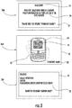
- the transparent viewing window (36A) initially has the TOLED electronic display (37) displaying a welcome message (51) which includes instructions (54) to a user (not shown).
- the transparent viewing window (36B) no longer carries a message, but a user (42) can view his/her cellphone (40) and barcode (44) displayed thereon under the transparent scanning window through the transparent viewing window (36B).
- a company logo (53) is displayed on the TOLED electronic display (37) simultaneously with the viewing of the cellphone (40) and barcode (44) through the transparent viewing window (36B).
- the transparent viewing window (36C) has the TOLED electronic display (37) displaying information (52) about the barcode (44) and the transaction. In the present Figure, this is shown as information about a purchase using a barcode coupon.
- the present invention further embraces a method of scanning and presenting decoded image information to a user using an image scanner.
- the image scanner is as hereinbefore described in conjunction with Figures 1-3 . That is, the image scanner may be comprised of a housing with an optical system within the housing.
- the optical system is comprised of a camera, a mirror, a transparent scanning window, and a transparent viewing window.
- the mirror is positioned such that incident light on the mirror from the transparent scanning window is in the camera's field of view.
- the transparent viewing window has an electronic display, preferably a TOLED.
- the transparent viewing window is positioned on the housing above the transparent scanning window such that images presented in the transparent scanning window can be seen by the presenter in the transparent viewing window.
- the method (200) is comprised of the steps of: (220) placing an image to be scanned under the transparent scanning window; (230) determining the image is placed correctly under the transparent scanning window by viewing the image through the transparent viewing window; (240) scanning the reflection of the image in the mirror with the camera; (250) decoding the scanned image with the image decoder; (260) sending the decoded image information to the electronic display; and (270) displaying the decoded image information on the electronic display.
- the method (200) may further comprise the step of (210) displaying a greeting on the electronic display before the placing step (220).
- the greeting may be displayed on the TOLED when a presenter of the image approaches the imaging scanner.
- the step of (210) displaying a greeting includes the step of (211) instructing a presenter of the image to be scanned where to place the image to be scanned.
- the step of (211) instructing a presenter of the image to be scanned where to place the image to be scanned before the placing step may be taken in the absence of the optional step (210) of displaying a greeting.
- the method (200) may further include the step of (212) displaying a company logo on the TOLED electronic display.
- the step of (212) displaying the company logo on the TOLED electronic display may accompany or be concurrent with the step of (210) displaying a greeting on the electronic display and/or with the step (211) of instructing a presenter of the image to be scanned where to place the image to be scanned.
- the step of (212) displaying the company logo on the TOLED electronic display may occur during any or all of the subsequent steps (220 - 260) of the method (200).
- the method (200) further comprises the step (271) of displaying the company logo on the electronic display concurrently with the step of (270) displaying the decoded image information on the electronic display.
- the sending step (260) is accomplished via a processor electronically linked to the image decoder and the electronic display as described hereinbefore in connection with Figures 1-3 ).
Landscapes
- Engineering & Computer Science (AREA)
- Multimedia (AREA)
- Signal Processing (AREA)
- Studio Devices (AREA)
Abstract
Description
- The present application claims the benefit of
Chinese Patent Application for Invention No. 201610557275.4 for an Imaging Scanner with Positioning and Display at the State Intellectual Property Office of the People's Republic of China on July 15, 2016 - The present invention relates to imaging scanners, and in particular to imaging scanners which provide feedback to users of the imaging scanner.
- Generally speaking when a user approaches an imaging scanner with a portable electronic device to scan a coupon or a barcode on the portable electronic device, the user cannot be sure that the portable electronic device is properly positioned under the imaging scanner to get the best scan.
- Additionally, usually there is no immediate feedback on the decoding of the presented image or barcode at imaging scanner.
- There have been other solutions in the art to solve some of these problems. For example,
US Patent No. 8,777,109 discloses a customer facing imaging scanner. The scanner includes an imaging unit in a C-shaped housing unit. The mobile screen to be imaged is placed on the lower surface of the housing facing upwards. The customer can view the mobile screen placed on the lower surface and make adjustments to the placement for a successful imaging. The upper portion of the scanner includes an electronic display to display advertisements or other information to the customers during the transaction. However, placing the mobile screen correctly on the lower surface for scanning is done by eye at an angle to the lower surface. Additionally, advertisements and other information may be displayed on a separate portion of the scanner (other than the lower surface), which may not be viewed simultaneously as with positioning the mobile screen. -
US Patent No. 5,266,788 provides a laser barcode scanner with a transparent support region. The customer can observe and confirm the barcode that is being scanned by viewing the barcode through the transparent support. A hologram may be reflected onto the transparent support to show information about the barcode scan. However, the customer is not holding the item to be scanned. For example, the mobile device that has the barcode to be scanned is held by the operator of the barcode scanner and not the customer. Additionally, the reflection-type hologram may be a complicated scheme. -
US Patent publication 2014035377 discloses an electronic device with a transparent display unit which can be any portable electronic device as in a smartphone or a barcode reader. The user can view the barcode to be displayed and scan the barcode in real time by viewing the barcode through the heads-up display on the electronic device. However, this device is limited to customer use as the scanner is in the customer's hands. Additionally, depending on the location of the barcodes with respect to the customer, the positioning of the barcode in the heads-up display may take several attempts for a successful scan. Additionally, the customer may not be able to isolate one barcode on the display if there are a number of barcodes close together. - Therefore, a need exists for an imaging scanner of simple operation for which an image to be scanned from a portable electronic device, such as a smartphone, can be accurately placed for successful scans by a presenter of the image, and for which the display of immediate feedback and/or other information is in the same field of view where the presenter is placing the image to be scanned.
- Accordingly, in one aspect, the present invention embraces an imaging scanner satisfying the hereinbefore described advantages.
- In an exemplary embodiment, the imaging scanner is comprised of a housing having a lower portion, an upper portion, and an end portion. The upper portion extends at a declining angle from the lower portion. The end portion extends at a declining angle from the upper portion. The imaging scanner is also comprised of a mirror. The mirror is positioned at a top surface inside the upper portion of the housing. The imaging scanner also includes a camera in the lower portion of the housing, a transparent window for scanning positioned on a lower end of the end portion, a transparent window for viewing on a top surface of the end portion and positioned above the transparent window for scanning, such that anything below the transparent window for scanning is visible in the transparent window for viewing. The transparent window for viewing has an electronic display embedded therein. The imaging scanner is additionally comprised of an image decoder. The image decoder is communicatively linked to the camera and to the electronic display. The mirror is positioned at the top surface such that incident light on the mirror from the transparent scanning window will be reflected within the camera's field of view. The camera is configured to scan images presented at the transparent window for scanning by a user and to send the scanned images to the image decoder. The image decoder is configured to decode the scanned images and to send the decoded image information to the electronic display. The electronic display is configured to display the decoded image information on the transparent window for viewing.
- In another exemplary embodiment, the imaging scanner further comprises a processor communicatively linked to the camera, the image decoder, and the electronic display. The processor is configured to implement the functions of the camera, and the image decoder, and to send display instructions to the electronic display.
- In another exemplary embodiment of the imaging scanner, the display instructions include instructions to display decoded image information, instructions to display greetings, and instructions to display guidelines to a user for presenting an image to be scanned below the transparent scanning window.
- In yet another exemplary embodiment of the imaging scanner, the electronic display is a TOLED (transparent organic light-emitting diode.)
- In another exemplary embodiment of the imaging scanner, the TOLED has an outer surface encased in transparent plastic.
- In another exemplary embodiment of the imaging scanner, the communicative link between the image decoder and the electronic display is wireless.
- In another exemplary embodiment of the imaging scanner, the communicative link between the image decoder and the electronic display is a hardwire link.
- In another exemplary embodiment of the imaging scanner, the image decoder is positioned within the lower portion of the housing.
- In another exemplary embodiment of the imaging scanner, the image decoder is positioned external to the image scanner.
- In another exemplary embodiment of the imaging scanner, the image presented at the transparent scanning window is a barcode. The image decoder is a barcode decoder.
- In another exemplary embodiment of the imaging scanner, a barcode is presented to the transparent window for scanning on an electronic device.
- In another exemplary embodiment of the imaging scanner, the electronic display is configured to display a company logo on the electronic display.
- In another aspect, the present invention embraces a method of scanning images and presenting decoded image information to a user using an image scanner. In the method of the present invention, the image scanner is comprised of a housing with an optical system within the housing. The optical system is comprised of a camera, a mirror, a transparent scanning window, and a transparent viewing window. The mirror is positioned such that incident light on the mirror from the transparent scanning window is in the camera's field of view. The transparent viewing window is a TOLED and includes an electronic display, being positioned on the housing above the transparent scanning window such that images presented in the transparent scanning window can be seen by the presenter in the transparent viewing window.
- In an exemplary embodiment, the method comprises the steps of: placing an image to be scanned under the transparent scanning window; determining the image is placed correctly under the transparent scanning window by viewing the image through the transparent viewing window; scanning the reflection of the image in the mirror with the camera; decoding the scanned image with an image decoder; sending the decoded image information to the electronic display; and displaying the decoded image information on the electronic display.
- In another exemplary embodiment, the method further comprises the step of displaying a greeting on the electronic display before the placing step.
- In another exemplary embodiment of the method, the step of displaying a greeting includes instructing a presenter of the image to be scanned where to place the image to be scanned.
- In another exemplary embodiment, the method further comprises the step of instructing a presenter of the image to be scanned where to place the image to be scanned before the placing step.
- In another exemplary embodiment of the method, the sending step is accomplished via a processor electronically linked to the image decoder and the electronic display.
- In another exemplary embodiment, the method further comprises the step of displaying a company logo on the electronic display.
- In another exemplary embodiment of the method, the step of displaying a company logo is concurrent with the step of displaying the decoded image information on the electronic display.
- In another exemplary embodiment, the method further comprises the step of displaying a company logo on the electronic display, the step of displaying a company logo being concurrent with the step of displaying a greeting on the electronic display.
- The foregoing illustrative summary, as well as other exemplary objectives and/or advantages of the invention, and the manner in which the same are accomplished, are further explained within the following detailed description and its accompanying drawings.
-
-
Figure 1 schematically depicts a cross-sectional perspective view of the imaging scanner in accordance with an exemplary embodiment of the present invention. -
Figure 2 schematically depicts another perspective view of the imaging scanner in accordance with an exemplary embodiment of the present invention. -
Figure 3 schematically depicts the transparent viewing window with a series of displays on the electronic display during a transaction in accordance with the present invention. -
Figure 4 schematically depicts in a flowchart, a method of scanning images and presenting decoded image information to a user using an image scanner in accordance with an exemplary embodiment of the present invention. - The present invention embraces an imaging scanner.
Figure 1 shows a cross-section of the imaging scanner (10) so that the interior portion of the imaging scanner (10) can be understood. The present application may also refer to the imaging scanner or image scanner as a device. - In an exemplary embodiment, as is depicted in
Figure 1 , the imaging scanner (10) has a housing (20), which is comprised of a lower portion (21), an upper portion (22), and an end portion (23). As can be seen in the present Figure, the imaging scanner (10) has a generally goose-neck shape. The upper portion (22) extends generally at a declining angle from the lower portion (21). The end portion (23) extends generally at a declining angle from the upper portion (22). - The housing (20) includes a mirror (30). The mirror is positioned at a top surface (24) inside the upper portion (22) of the housing (20).
- The imaging scanner (10) also includes a camera (32) positioned in the lower portion (21) of the housing (20).
- A transparent window for scanning (34) is positioned on a lower end (25) of the end portion (23) of the housing (20).
- A transparent window for viewing (36) is positioned on a top surface (26) of the end portion (23) and positioned above the transparent window for scanning (34), such that anything below the transparent window for scanning (34) is visible in the transparent window for viewing (36). Shown in the Figure, a cellphone (40) or another handheld electronic device is presented below the transparent window for scanning (34). The presenter (42) of the cellphone (40) is partially shown looking through the transparent window for viewing (36) and can see that the cellphone (40) is centered correctly under the transparent window for scanning (34).
- The transparent window for viewing (36) is provided with an electronic display (37) embedded therein.
- The imaging scanner is further includes an image decoder (38). The image decoder (38) is communicatively linked to the camera (32) and to the electronic display (37) of the transparent window for viewing (36). The communicative links are shown in the Figure by dotted lines within the housing between components.
- The mirror (30) is positioned at the top surface (24) such that incident light on the mirror (30) from the transparent scanning window (34) will be reflected within the camera's (32) field of view. This is shown in the Figure by ray lines (61, 62, 63, and 64).
- The camera (32) being configured to scan images, as on a cellphone (40) presented at the transparent window for scanning (34) by a user and to send the scanned images to the image decoder (38). The image decoder (38) being configured to decode the scanned images and to send the decoded image information to the electronic display on the transparent window for viewing (36). The electronic display (37) is configured to display the decoded image information on the transparent window for viewing (36).
- In another exemplary embodiment, still referring to the present figure, the image scanner (10) further includes a processor (39). The processor (39) is communicatively linked to the camera (32), the image decoder (38), and the electronic display (7). Further, the processor (39) being configured to implement the functions of the camera (32), the image decoder (38), and to send display instructions to the electronic display (37).
- In another exemplary embodiment, the electronic display (37) is a TOLED. Additionally, the outer surface of the TOLED may be encased in transparent plastic (not shown).
- In an exemplary embodiment, the image decoder (38) is positioned within the lower portion (21) of the housing (20) as shown in the
Figure 1 . Alternatively, the image decoder (38) may be positioned external to the image scanner (30) (this configuration not shown). - The links between the processor (37), the camera (32), the image decoder (38), and the electronic display (37), may be wireless, hardwire, or combinations thereof. In the Figure, the links are shown as dotted lines between these components.
- Referring now to
Figure 2 , the image scanner (10) is shown from above the transparent viewing window (36). The housing (20) and lower portion (21), upper portion (22), and end portion (23) are designated as in the previous Figure, as are the top surface (24) of the upper portion (22), the top surface (26) of the end portion (23), and the lower end (25) of the end portion (23). From this perspective, a cellphone (40) is being presented under the transparent scanning window (34) by a user (42). The cellphone (40) displays a barcode (44). The TOLED electronic display (37) is transparent, not displaying any information, and thus, the barcode (44) can be seen through the transparent viewing window (36). - Referring now to
Figure 3 , an example of what the transparent viewing window (36) and the TOLED electronic display may look like during a transaction is depicted. - The transparent viewing window (36A) initially has the TOLED electronic display (37) displaying a welcome message (51) which includes instructions (54) to a user (not shown). Next, the transparent viewing window (36B) no longer carries a message, but a user (42) can view his/her cellphone (40) and barcode (44) displayed thereon under the transparent scanning window through the transparent viewing window (36B). Optionally, a company logo (53) is displayed on the TOLED electronic display (37) simultaneously with the viewing of the cellphone (40) and barcode (44) through the transparent viewing window (36B). After the barcode (44) is scanned by the camera (not shown in this Figure), the transparent viewing window (36C) has the TOLED electronic display (37) displaying information (52) about the barcode (44) and the transaction. In the present Figure, this is shown as information about a purchase using a barcode coupon.
- The present invention further embraces a method of scanning and presenting decoded image information to a user using an image scanner. In an exemplary embodiment, the image scanner is as hereinbefore described in conjunction with
Figures 1-3 . That is, the image scanner may be comprised of a housing with an optical system within the housing. The optical system is comprised of a camera, a mirror, a transparent scanning window, and a transparent viewing window. The mirror is positioned such that incident light on the mirror from the transparent scanning window is in the camera's field of view. The transparent viewing window has an electronic display, preferably a TOLED. The transparent viewing window is positioned on the housing above the transparent scanning window such that images presented in the transparent scanning window can be seen by the presenter in the transparent viewing window. - In an exemplary embodiment of the method (200), referring to
Figure 4 , is comprised of the steps of: (220) placing an image to be scanned under the transparent scanning window; (230) determining the image is placed correctly under the transparent scanning window by viewing the image through the transparent viewing window; (240) scanning the reflection of the image in the mirror with the camera; (250) decoding the scanned image with the image decoder; (260) sending the decoded image information to the electronic display; and (270) displaying the decoded image information on the electronic display. - In another exemplary embodiment, the method (200) may further comprise the step of (210) displaying a greeting on the electronic display before the placing step (220). Thus, the greeting may be displayed on the TOLED when a presenter of the image approaches the imaging scanner.
- In another exemplary embodiment of the method (200), the step of (210) displaying a greeting includes the step of (211) instructing a presenter of the image to be scanned where to place the image to be scanned.
- Alternatively, in another exemplary embodiment of the method (200), the step of (211) instructing a presenter of the image to be scanned where to place the image to be scanned before the placing step may be taken in the absence of the optional step (210) of displaying a greeting.
- Alternatively, or additionally, in another exemplary embodiment, the method (200) may further include the step of (212) displaying a company logo on the TOLED electronic display.
- The step of (212) displaying the company logo on the TOLED electronic display, in another exemplary embodiment, may accompany or be concurrent with the step of (210) displaying a greeting on the electronic display and/or with the step (211) of instructing a presenter of the image to be scanned where to place the image to be scanned.
- In another exemplary embodiment of the method (200), the step of (212) displaying the company logo on the TOLED electronic display may occur during any or all of the subsequent steps (220 - 260) of the method (200).
- In another exemplary embodiment, the method (200) further comprises the step (271) of displaying the company logo on the electronic display concurrently with the step of (270) displaying the decoded image information on the electronic display.
- In another exemplary embodiment of the method (200), the sending step (260) is accomplished via a processor electronically linked to the image decoder and the electronic display as described hereinbefore in connection with
Figures 1-3 ). - In the specification and/or figures, typical embodiments of the invention have been disclosed. The present invention is not limited to such exemplary embodiments. The use of the term "and/or" includes any and all combinations of one or more of the associated listed items. The figures are schematic representations and so are not necessarily drawn to scale. Unless otherwise noted, specific terms have been used in a generic and descriptive sense and not for purposes of limitation.
Claims (15)
- A device, comprising:a housing having a lower portion, an upper portion, and an end portion, the upper portion extending at a declining angle from the lower portion, the end portion extending at a declining angle from the upper portion;a mirror, the mirror being positioned at a top surface inside the upper portion of the housing;a camera in the lower portion of the housing;a transparent window for scanning positioned on a lower end of the end portion;a transparent window for viewing on a top surface of the end portion and positioned above the transparent window for scanning, such that at least a portion of the area below the transparent window for scanning is visible in the transparent window for viewing, the transparent window for viewing having an electronic display embedded therein;an image decoder, the image decoder being communicatively linked to the camera and to the electronic display;the mirror being positioned at the top surface such that light incident on the mirror from the transparent scanning window will be reflected within the camera's field of view;the camera being configured to scan images presented at the transparent window for scanning by a user and to send the scanned images to the image decoder;the image decoder being configured to decode the scanned images and to send the decoded image information to the electronic display; andthe electronic display being configured to display the decoded image information on the transparent window for viewing.
- The device of claim 1, further comprising a processor communicatively linked to the camera, the image decoder, and the electronic display; the processor being configured to implement the functions of the camera, the image decoder, and to send display instructions to the electronic display.
- The device of claim 2, wherein the display instructions include instructions to display decoded image information, instructions to display greetings, and instructions to display guidelines to a user for presenting an image to be scanned below the transparent scanning window.
- The device of claim 1, wherein the electronic display is a TOLED (transparent organic light-emitting diode.)
- The device of claim 4, wherein the TOLED has an outer surface encased in transparent plastic.
- The device of claim 1, wherein the communicative link between the image decoder and the electronic display is wireless.
- The device of claim 1, wherein the communicative link between the image decoder and the electronic display is a hardwire link.
- The device of claim 1, wherein the image decoder is positioned within the lower portion of the housing.
- The device of claim 1, wherein the image decoder is positioned external to the image device.
- The device of claim 1, wherein the image presented at the transparent scanning window is a barcode; and wherein the image decoder is a barcode decoder.
- The device of claim 9, wherein a barcode is presented to the transparent window for scanning on an electronic device.
- The device of claim 1, wherein the electronic display is configured to display a company logo on the electronic display.
- A method, comprising:an image scanner comprised of a housing with an optical system within the housing, the optical system being comprised of a camera, a mirror, a transparent scanning window, and a transparent viewing window; the mirror being positioned such that incident light on the mirror from the transparent scanning window is in the camera's field of view; the transparent viewing window having a TOLED electronic display and being positioned on the housing above the transparent scanning window such that images presented in the transparent scanning window can be seen by the presenter in the transparent viewing window; the method comprising the steps of:placing an image to be scanned under a transparent scanning window of a device, the device comprising a housing and an optical system, the optical system comprising a camera, a mirror, a transparent scanning window, and the transparent viewing window, wherein the mirror is positioned such that incident light on the mirror from the transparent scanning window is in the camera's field of view, and wherein the transparent viewing window has a TOLED electronic display and is positioned on the housing above the transparent scanning window such that images presented in the transparent scanning window can be seen by the presenter in the transparent viewing window;determining the image is placed correctly under the transparent scanning window by viewing the image through the transparent viewing window;scanning the reflection of the image in the mirror with the camera;decoding the scanned image with the image decoder;sending the decoded image information to the electronic display; anddisplaying the decoded image information on the electronic display.
- The method of claim 13, further comprising the step of displaying a greeting on the electronic display before the placing step.
- The method of claim 14, wherein the step of displaying a greeting includes instructing a presenter of the image to be scanned where to place the image to be scanned.
Applications Claiming Priority (2)
| Application Number | Priority Date | Filing Date | Title |
|---|---|---|---|
| CN201610557275.4A CN107622217B (en) | 2016-07-15 | 2016-07-15 | Imaging scanner with positioning and display |
| US15/622,620 US10210366B2 (en) | 2016-07-15 | 2017-06-14 | Imaging scanner with positioning and display |
Publications (2)
| Publication Number | Publication Date |
|---|---|
| EP3270580A1 true EP3270580A1 (en) | 2018-01-17 |
| EP3270580B1 EP3270580B1 (en) | 2021-09-01 |
Family
ID=59253430
Family Applications (1)
| Application Number | Title | Priority Date | Filing Date |
|---|---|---|---|
| EP17178532.2A Active EP3270580B1 (en) | 2016-07-15 | 2017-06-28 | Imaging scanner with positioning and display |
Country Status (1)
| Country | Link |
|---|---|
| EP (1) | EP3270580B1 (en) |
Citations (8)
| Publication number | Priority date | Publication date | Assignee | Title |
|---|---|---|---|---|
| US5266788A (en) | 1989-09-18 | 1993-11-30 | Fujitsu Limited | Laser scanner for bar code reader having a transparent light guide plate |
| WO2002080106A2 (en) * | 2001-03-30 | 2002-10-10 | Koninklijke Philips Electronics N.V. | Method, system and device for augmented reality |
| US20060065714A1 (en) * | 2004-09-28 | 2006-03-30 | 3M Innovative Properties Company | Passport reader for processing a passport having an RFID element |
| US8139049B1 (en) * | 2004-03-17 | 2012-03-20 | Socket Mobile, Inc. | Cordless scanner and stylus |
| US20140035377A1 (en) | 2007-03-30 | 2014-02-06 | David L. Klein | Localized power point optimizer for solar cell installations |
| US8777109B2 (en) | 2012-10-04 | 2014-07-15 | Hand Held Products, Inc. | Customer facing imaging systems and methods for obtaining images |
| US20140353377A1 (en) * | 2013-05-29 | 2014-12-04 | Symbol Technologies, Inc | Transparent display for data collection engine |
| US20150154801A1 (en) * | 2013-11-29 | 2015-06-04 | Samsung Electronics Co., Ltd. | Electronic device including transparent display and method of controlling the electronic device |
-
2017
- 2017-06-28 EP EP17178532.2A patent/EP3270580B1/en active Active
Patent Citations (8)
| Publication number | Priority date | Publication date | Assignee | Title |
|---|---|---|---|---|
| US5266788A (en) | 1989-09-18 | 1993-11-30 | Fujitsu Limited | Laser scanner for bar code reader having a transparent light guide plate |
| WO2002080106A2 (en) * | 2001-03-30 | 2002-10-10 | Koninklijke Philips Electronics N.V. | Method, system and device for augmented reality |
| US8139049B1 (en) * | 2004-03-17 | 2012-03-20 | Socket Mobile, Inc. | Cordless scanner and stylus |
| US20060065714A1 (en) * | 2004-09-28 | 2006-03-30 | 3M Innovative Properties Company | Passport reader for processing a passport having an RFID element |
| US20140035377A1 (en) | 2007-03-30 | 2014-02-06 | David L. Klein | Localized power point optimizer for solar cell installations |
| US8777109B2 (en) | 2012-10-04 | 2014-07-15 | Hand Held Products, Inc. | Customer facing imaging systems and methods for obtaining images |
| US20140353377A1 (en) * | 2013-05-29 | 2014-12-04 | Symbol Technologies, Inc | Transparent display for data collection engine |
| US20150154801A1 (en) * | 2013-11-29 | 2015-06-04 | Samsung Electronics Co., Ltd. | Electronic device including transparent display and method of controlling the electronic device |
Also Published As
| Publication number | Publication date |
|---|---|
| EP3270580B1 (en) | 2021-09-01 |
Similar Documents
| Publication | Publication Date | Title |
|---|---|---|
| CN105740743B (en) | Augmented reality visual barcode scanning system and method | |
| US9250712B1 (en) | Method and application for scanning a barcode with a smart device while continuously running and displaying an application on the smart device display | |
| US20090218405A1 (en) | Imaging System for Reading Mobile Device Indicia | |
| US8295640B2 (en) | Noise reduction by image subtraction in an automatic data collection device, such as an image acquisition device | |
| US9747482B2 (en) | Aimer accessory for capturing a coded image | |
| US11176401B2 (en) | Method and system for acquiring multi-angle images of a product | |
| US20130320091A1 (en) | Methods and Apparatus for Positioning an Optical Code for Imaging Scanning | |
| EP1585019A3 (en) | Apparatus and method for displaying menus in a portable terminal | |
| CN111756946A (en) | Capturing graphical information presentation | |
| EP2575073B1 (en) | Control of an imaging scanner | |
| US20170178108A1 (en) | Pos-terminal device | |
| US20180152668A1 (en) | Information display system and information display terminal | |
| US9990526B2 (en) | System for capturing a coded image | |
| KR102542053B1 (en) | A kiosk apparatus for education and a system comprising the same | |
| EP3270580B1 (en) | Imaging scanner with positioning and display | |
| JP2011048426A (en) | Cooking auxiliary terminal and program | |
| CN103677707A (en) | Display method and portable device | |
| EP2988247B1 (en) | Data entry device with enhanced aiming | |
| US20240203214A1 (en) | Mounted Customer Service System with Integrated Media Processing Device | |
| TW201411439A (en) | Displaying method and portable device | |
| US10210366B2 (en) | Imaging scanner with positioning and display | |
| JP2008507003A (en) | Two-dimensional symbol reading system having a guide window for confirmation | |
| CN202373084U (en) | Hand-held scanner | |
| CN102622826A (en) | Handheld scanning equipment | |
| JP2016110226A (en) | Reader |
Legal Events
| Date | Code | Title | Description |
|---|---|---|---|
| PUAI | Public reference made under article 153(3) epc to a published international application that has entered the european phase |
Free format text: ORIGINAL CODE: 0009012 |
|
| STAA | Information on the status of an ep patent application or granted ep patent |
Free format text: STATUS: REQUEST FOR EXAMINATION WAS MADE |
|
| 17P | Request for examination filed |
Effective date: 20170628 |
|
| AK | Designated contracting states |
Kind code of ref document: A1 Designated state(s): AL AT BE BG CH CY CZ DE DK EE ES FI FR GB GR HR HU IE IS IT LI LT LU LV MC MK MT NL NO PL PT RO RS SE SI SK SM TR |
|
| AX | Request for extension of the european patent |
Extension state: BA ME |
|
| GRAP | Despatch of communication of intention to grant a patent |
Free format text: ORIGINAL CODE: EPIDOSNIGR1 |
|
| STAA | Information on the status of an ep patent application or granted ep patent |
Free format text: STATUS: GRANT OF PATENT IS INTENDED |
|
| INTG | Intention to grant announced |
Effective date: 20210326 |
|
| GRAS | Grant fee paid |
Free format text: ORIGINAL CODE: EPIDOSNIGR3 |
|
| GRAA | (expected) grant |
Free format text: ORIGINAL CODE: 0009210 |
|
| STAA | Information on the status of an ep patent application or granted ep patent |
Free format text: STATUS: THE PATENT HAS BEEN GRANTED |
|
| AK | Designated contracting states |
Kind code of ref document: B1 Designated state(s): AL AT BE BG CH CY CZ DE DK EE ES FI FR GB GR HR HU IE IS IT LI LT LU LV MC MK MT NL NO PL PT RO RS SE SI SK SM TR |
|
| REG | Reference to a national code |
Ref country code: GB Ref legal event code: FG4D |
|
| REG | Reference to a national code |
Ref country code: CH Ref legal event code: EP Ref country code: AT Ref legal event code: REF Ref document number: 1427473 Country of ref document: AT Kind code of ref document: T Effective date: 20210915 |
|
| REG | Reference to a national code |
Ref country code: DE Ref legal event code: R096 Ref document number: 602017045029 Country of ref document: DE |
|
| REG | Reference to a national code |
Ref country code: IE Ref legal event code: FG4D |
|
| REG | Reference to a national code |
Ref country code: LT Ref legal event code: MG9D |
|
| REG | Reference to a national code |
Ref country code: NL Ref legal event code: MP Effective date: 20210901 |
|
| PG25 | Lapsed in a contracting state [announced via postgrant information from national office to epo] |
Ref country code: LT Free format text: LAPSE BECAUSE OF FAILURE TO SUBMIT A TRANSLATION OF THE DESCRIPTION OR TO PAY THE FEE WITHIN THE PRESCRIBED TIME-LIMIT Effective date: 20210901 Ref country code: BG Free format text: LAPSE BECAUSE OF FAILURE TO SUBMIT A TRANSLATION OF THE DESCRIPTION OR TO PAY THE FEE WITHIN THE PRESCRIBED TIME-LIMIT Effective date: 20211201 Ref country code: NO Free format text: LAPSE BECAUSE OF FAILURE TO SUBMIT A TRANSLATION OF THE DESCRIPTION OR TO PAY THE FEE WITHIN THE PRESCRIBED TIME-LIMIT Effective date: 20211201 Ref country code: ES Free format text: LAPSE BECAUSE OF FAILURE TO SUBMIT A TRANSLATION OF THE DESCRIPTION OR TO PAY THE FEE WITHIN THE PRESCRIBED TIME-LIMIT Effective date: 20210901 Ref country code: FI Free format text: LAPSE BECAUSE OF FAILURE TO SUBMIT A TRANSLATION OF THE DESCRIPTION OR TO PAY THE FEE WITHIN THE PRESCRIBED TIME-LIMIT Effective date: 20210901 Ref country code: HR Free format text: LAPSE BECAUSE OF FAILURE TO SUBMIT A TRANSLATION OF THE DESCRIPTION OR TO PAY THE FEE WITHIN THE PRESCRIBED TIME-LIMIT Effective date: 20210901 Ref country code: SE Free format text: LAPSE BECAUSE OF FAILURE TO SUBMIT A TRANSLATION OF THE DESCRIPTION OR TO PAY THE FEE WITHIN THE PRESCRIBED TIME-LIMIT Effective date: 20210901 Ref country code: RS Free format text: LAPSE BECAUSE OF FAILURE TO SUBMIT A TRANSLATION OF THE DESCRIPTION OR TO PAY THE FEE WITHIN THE PRESCRIBED TIME-LIMIT Effective date: 20210901 |
|
| REG | Reference to a national code |
Ref country code: AT Ref legal event code: MK05 Ref document number: 1427473 Country of ref document: AT Kind code of ref document: T Effective date: 20210901 |
|
| PG25 | Lapsed in a contracting state [announced via postgrant information from national office to epo] |
Ref country code: PL Free format text: LAPSE BECAUSE OF FAILURE TO SUBMIT A TRANSLATION OF THE DESCRIPTION OR TO PAY THE FEE WITHIN THE PRESCRIBED TIME-LIMIT Effective date: 20210901 Ref country code: LV Free format text: LAPSE BECAUSE OF FAILURE TO SUBMIT A TRANSLATION OF THE DESCRIPTION OR TO PAY THE FEE WITHIN THE PRESCRIBED TIME-LIMIT Effective date: 20210901 Ref country code: GR Free format text: LAPSE BECAUSE OF FAILURE TO SUBMIT A TRANSLATION OF THE DESCRIPTION OR TO PAY THE FEE WITHIN THE PRESCRIBED TIME-LIMIT Effective date: 20211202 |
|
| PG25 | Lapsed in a contracting state [announced via postgrant information from national office to epo] |
Ref country code: AT Free format text: LAPSE BECAUSE OF FAILURE TO SUBMIT A TRANSLATION OF THE DESCRIPTION OR TO PAY THE FEE WITHIN THE PRESCRIBED TIME-LIMIT Effective date: 20210901 |
|
| PG25 | Lapsed in a contracting state [announced via postgrant information from national office to epo] |
Ref country code: IS Free format text: LAPSE BECAUSE OF FAILURE TO SUBMIT A TRANSLATION OF THE DESCRIPTION OR TO PAY THE FEE WITHIN THE PRESCRIBED TIME-LIMIT Effective date: 20220101 Ref country code: SM Free format text: LAPSE BECAUSE OF FAILURE TO SUBMIT A TRANSLATION OF THE DESCRIPTION OR TO PAY THE FEE WITHIN THE PRESCRIBED TIME-LIMIT Effective date: 20210901 Ref country code: SK Free format text: LAPSE BECAUSE OF FAILURE TO SUBMIT A TRANSLATION OF THE DESCRIPTION OR TO PAY THE FEE WITHIN THE PRESCRIBED TIME-LIMIT Effective date: 20210901 Ref country code: RO Free format text: LAPSE BECAUSE OF FAILURE TO SUBMIT A TRANSLATION OF THE DESCRIPTION OR TO PAY THE FEE WITHIN THE PRESCRIBED TIME-LIMIT Effective date: 20210901 Ref country code: PT Free format text: LAPSE BECAUSE OF FAILURE TO SUBMIT A TRANSLATION OF THE DESCRIPTION OR TO PAY THE FEE WITHIN THE PRESCRIBED TIME-LIMIT Effective date: 20220103 Ref country code: NL Free format text: LAPSE BECAUSE OF FAILURE TO SUBMIT A TRANSLATION OF THE DESCRIPTION OR TO PAY THE FEE WITHIN THE PRESCRIBED TIME-LIMIT Effective date: 20210901 Ref country code: EE Free format text: LAPSE BECAUSE OF FAILURE TO SUBMIT A TRANSLATION OF THE DESCRIPTION OR TO PAY THE FEE WITHIN THE PRESCRIBED TIME-LIMIT Effective date: 20210901 Ref country code: CZ Free format text: LAPSE BECAUSE OF FAILURE TO SUBMIT A TRANSLATION OF THE DESCRIPTION OR TO PAY THE FEE WITHIN THE PRESCRIBED TIME-LIMIT Effective date: 20210901 Ref country code: AL Free format text: LAPSE BECAUSE OF FAILURE TO SUBMIT A TRANSLATION OF THE DESCRIPTION OR TO PAY THE FEE WITHIN THE PRESCRIBED TIME-LIMIT Effective date: 20210901 |
|
| REG | Reference to a national code |
Ref country code: DE Ref legal event code: R097 Ref document number: 602017045029 Country of ref document: DE |
|
| PLBE | No opposition filed within time limit |
Free format text: ORIGINAL CODE: 0009261 |
|
| STAA | Information on the status of an ep patent application or granted ep patent |
Free format text: STATUS: NO OPPOSITION FILED WITHIN TIME LIMIT |
|
| PG25 | Lapsed in a contracting state [announced via postgrant information from national office to epo] |
Ref country code: IT Free format text: LAPSE BECAUSE OF FAILURE TO SUBMIT A TRANSLATION OF THE DESCRIPTION OR TO PAY THE FEE WITHIN THE PRESCRIBED TIME-LIMIT Effective date: 20210901 Ref country code: DK Free format text: LAPSE BECAUSE OF FAILURE TO SUBMIT A TRANSLATION OF THE DESCRIPTION OR TO PAY THE FEE WITHIN THE PRESCRIBED TIME-LIMIT Effective date: 20210901 |
|
| 26N | No opposition filed |
Effective date: 20220602 |
|
| PG25 | Lapsed in a contracting state [announced via postgrant information from national office to epo] |
Ref country code: SI Free format text: LAPSE BECAUSE OF FAILURE TO SUBMIT A TRANSLATION OF THE DESCRIPTION OR TO PAY THE FEE WITHIN THE PRESCRIBED TIME-LIMIT Effective date: 20210901 |
|
| PG25 | Lapsed in a contracting state [announced via postgrant information from national office to epo] |
Ref country code: MC Free format text: LAPSE BECAUSE OF FAILURE TO SUBMIT A TRANSLATION OF THE DESCRIPTION OR TO PAY THE FEE WITHIN THE PRESCRIBED TIME-LIMIT Effective date: 20210901 |
|
| REG | Reference to a national code |
Ref country code: CH Ref legal event code: PL |
|
| REG | Reference to a national code |
Ref country code: BE Ref legal event code: MM Effective date: 20220630 |
|
| PG25 | Lapsed in a contracting state [announced via postgrant information from national office to epo] |
Ref country code: LU Free format text: LAPSE BECAUSE OF NON-PAYMENT OF DUE FEES Effective date: 20220628 Ref country code: LI Free format text: LAPSE BECAUSE OF NON-PAYMENT OF DUE FEES Effective date: 20220630 Ref country code: IE Free format text: LAPSE BECAUSE OF NON-PAYMENT OF DUE FEES Effective date: 20220628 Ref country code: CH Free format text: LAPSE BECAUSE OF NON-PAYMENT OF DUE FEES Effective date: 20220630 |
|
| PG25 | Lapsed in a contracting state [announced via postgrant information from national office to epo] |
Ref country code: BE Free format text: LAPSE BECAUSE OF NON-PAYMENT OF DUE FEES Effective date: 20220630 |
|
| PG25 | Lapsed in a contracting state [announced via postgrant information from national office to epo] |
Ref country code: HU Free format text: LAPSE BECAUSE OF FAILURE TO SUBMIT A TRANSLATION OF THE DESCRIPTION OR TO PAY THE FEE WITHIN THE PRESCRIBED TIME-LIMIT; INVALID AB INITIO Effective date: 20170628 |
|
| PG25 | Lapsed in a contracting state [announced via postgrant information from national office to epo] |
Ref country code: MK Free format text: LAPSE BECAUSE OF FAILURE TO SUBMIT A TRANSLATION OF THE DESCRIPTION OR TO PAY THE FEE WITHIN THE PRESCRIBED TIME-LIMIT Effective date: 20210901 Ref country code: CY Free format text: LAPSE BECAUSE OF FAILURE TO SUBMIT A TRANSLATION OF THE DESCRIPTION OR TO PAY THE FEE WITHIN THE PRESCRIBED TIME-LIMIT Effective date: 20210901 |
|
| PG25 | Lapsed in a contracting state [announced via postgrant information from national office to epo] |
Ref country code: MT Free format text: LAPSE BECAUSE OF FAILURE TO SUBMIT A TRANSLATION OF THE DESCRIPTION OR TO PAY THE FEE WITHIN THE PRESCRIBED TIME-LIMIT Effective date: 20210901 |
|
| PG25 | Lapsed in a contracting state [announced via postgrant information from national office to epo] |
Ref country code: TR Free format text: LAPSE BECAUSE OF FAILURE TO SUBMIT A TRANSLATION OF THE DESCRIPTION OR TO PAY THE FEE WITHIN THE PRESCRIBED TIME-LIMIT Effective date: 20210901 |
|
| PGFP | Annual fee paid to national office [announced via postgrant information from national office to epo] |
Ref country code: GB Payment date: 20260622 Year of fee payment: 10 |
|
| PGFP | Annual fee paid to national office [announced via postgrant information from national office to epo] |
Ref country code: DE Payment date: 20260623 Year of fee payment: 10 |
|
| PGFP | Annual fee paid to national office [announced via postgrant information from national office to epo] |
Ref country code: FR Payment date: 20260622 Year of fee payment: 10 |