EP3270465A1 - Socket - Google Patents
Socket Download PDFInfo
- Publication number
- EP3270465A1 EP3270465A1 EP17176888.0A EP17176888A EP3270465A1 EP 3270465 A1 EP3270465 A1 EP 3270465A1 EP 17176888 A EP17176888 A EP 17176888A EP 3270465 A1 EP3270465 A1 EP 3270465A1
- Authority
- EP
- European Patent Office
- Prior art keywords
- relay
- mounting
- stopper
- restriction
- socket
- Prior art date
- Legal status (The legal status is an assumption and is not a legal conclusion. Google has not performed a legal analysis and makes no representation as to the accuracy of the status listed.)
- Granted
Links
Images


Classifications
-
- H—ELECTRICITY
- H01—ELECTRIC ELEMENTS
- H01R—ELECTRICALLY-CONDUCTIVE CONNECTIONS; STRUCTURAL ASSOCIATIONS OF A PLURALITY OF MUTUALLY-INSULATED ELECTRICAL CONNECTING ELEMENTS; COUPLING DEVICES; CURRENT COLLECTORS
- H01R13/00—Details of coupling devices of the kinds covered by groups H01R12/70 or H01R24/00 - H01R33/00
- H01R13/62—Means for facilitating engagement or disengagement of coupling parts or for holding them in engagement
- H01R13/629—Additional means for facilitating engagement or disengagement of coupling parts, e.g. aligning or guiding means, levers, gas pressure electrical locking indicators, manufacturing tolerances
- H01R13/62933—Comprising exclusively pivoting lever
- H01R13/62955—Pivoting lever comprising supplementary/additional locking means
-
- H—ELECTRICITY
- H01—ELECTRIC ELEMENTS
- H01R—ELECTRICALLY-CONDUCTIVE CONNECTIONS; STRUCTURAL ASSOCIATIONS OF A PLURALITY OF MUTUALLY-INSULATED ELECTRICAL CONNECTING ELEMENTS; COUPLING DEVICES; CURRENT COLLECTORS
- H01R13/00—Details of coupling devices of the kinds covered by groups H01R12/70 or H01R24/00 - H01R33/00
- H01R13/62—Means for facilitating engagement or disengagement of coupling parts or for holding them in engagement
- H01R13/629—Additional means for facilitating engagement or disengagement of coupling parts, e.g. aligning or guiding means, levers, gas pressure electrical locking indicators, manufacturing tolerances
- H01R13/631—Additional means for facilitating engagement or disengagement of coupling parts, e.g. aligning or guiding means, levers, gas pressure electrical locking indicators, manufacturing tolerances for engagement only
-
- H—ELECTRICITY
- H01—ELECTRIC ELEMENTS
- H01R—ELECTRICALLY-CONDUCTIVE CONNECTIONS; STRUCTURAL ASSOCIATIONS OF A PLURALITY OF MUTUALLY-INSULATED ELECTRICAL CONNECTING ELEMENTS; COUPLING DEVICES; CURRENT COLLECTORS
- H01R9/00—Structural associations of a plurality of mutually-insulated electrical connecting elements, e.g. terminal strips or terminal blocks; Terminals or binding posts mounted upon a base or in a case; Bases therefor
- H01R9/22—Bases, e.g. strip, block, panel
- H01R9/24—Terminal blocks
- H01R9/26—Clip-on terminal blocks for side-by-side rail- or strip-mounting
- H01R9/2625—Clip-on terminal blocks for side-by-side rail- or strip-mounting with built-in electrical component
- H01R9/2633—Clip-on terminal blocks for side-by-side rail- or strip-mounting with built-in electrical component with built-in switch
-
- H—ELECTRICITY
- H01—ELECTRIC ELEMENTS
- H01R—ELECTRICALLY-CONDUCTIVE CONNECTIONS; STRUCTURAL ASSOCIATIONS OF A PLURALITY OF MUTUALLY-INSULATED ELECTRICAL CONNECTING ELEMENTS; COUPLING DEVICES; CURRENT COLLECTORS
- H01R13/00—Details of coupling devices of the kinds covered by groups H01R12/70 or H01R24/00 - H01R33/00
- H01R13/62—Means for facilitating engagement or disengagement of coupling parts or for holding them in engagement
- H01R13/629—Additional means for facilitating engagement or disengagement of coupling parts, e.g. aligning or guiding means, levers, gas pressure electrical locking indicators, manufacturing tolerances
- H01R13/633—Additional means for facilitating engagement or disengagement of coupling parts, e.g. aligning or guiding means, levers, gas pressure electrical locking indicators, manufacturing tolerances for disengagement only
- H01R13/635—Additional means for facilitating engagement or disengagement of coupling parts, e.g. aligning or guiding means, levers, gas pressure electrical locking indicators, manufacturing tolerances for disengagement only by mechanical pressure, e.g. spring force
Definitions
- a relay is held by the protrusions each provided on each of the pair of support walls or by a stopper extending toward the socket body from the operation part.
- the socket 100 is a member configured to electrically connect terminals of a detachably mounted relay 1, conductor parts of electric wires, and electrodes on the board with one another, and after the socket 100 is assembled on the board, only the relay 1 is detachable to the socket body 10 of the socket 100, so that it is easy to repair or replace the relay 1.
- An example of the relay 1 is an elongated rectangular box shaped relay for board-mount use and has a coil 2 at one internal end, in the longitudinal direction, of the relay 1 as shown in Fig. 1 . Further, a plurality of terminals (not shown) are provided on the lower side surface, in the Y direction, of the relay 1. Note that the relay 1 is mounted in the socket body 10 in the direction Z1 (directed from up to down) in Fig. 1 and removed from the socket body 10 in the direction Z2 (directed from down to up) in Fig. 1 . That is, the mounting direction of the relay 1 with respect to the socket body 10 is Z1, and the removing direction is Z2.
- the position at which the relay 1 is mounted on the relay mounting surface 111 shown in Fig. 1 is defined as a mounting position of the relay 1.
- restriction release position is the position at which the stopper 30 at the restriction position III has been rotated by 180 degrees, and the main body 31 of the stopper 30 at the restriction position III and the main body 31 of the stopper 30 at the restriction release position IV are positioned on the same straight line perpendicular to the rotation axis X3 of the stopper 30.
- the pair of restriction flat parts 315 of the stopper 30 comes in contact with the both end parts in the width direction of the upper surface of the relay 1, and the flat part 314 between the pair of restriction flat parts 315 of the stopper 30 covers, in the plan view in which the relay 1 is viewed from the mounting direction Z1, a center-of-gravity position P of the relay 1 as shown in Fig. 7 .
- the stopper In a conventional socket in which a relay is detachable, the stopper is at the end part away from the center-of-gravity position of the relay in the plan view from the mounting direction; therefore, the force for holding the relay at the mounting position is so weak that the relay may unintentionally fall off from the mounting position when a vibration or impact is applied to the conventional socket.
- the stopper 130 is provided on the opposing inner surfaces of the pair of support walls 21, is supported in guide grooves 131 as an example of a guide part which guides the stopper 130 in the Y direction, and can slidingly move between the restriction position III and the restriction release position IV.
Landscapes
- Details Of Connecting Devices For Male And Female Coupling (AREA)
- Connecting Device With Holders (AREA)
Abstract
Description
- This application is based on
Japanese Patent Application No. 2016-139527 filed with the Japan Patent Office on July 14, 2016 - The invention relates to a socket to which a relay is detachable.
- In general, a relay is wired through a socket in some cases. Examples of such a socket include one described in
EP1052731 . That socket is equipped with: a socket body configured to be mounted on a board and having a mounting part on which a relay is to be mounted from a predetermined mounting direction; and a holding lever supported on the mounting part of the socket body and configured to hold a relay mounted on the mounting part. - The holding lever of the socket has: a pair of support walls, which is disposed to sandwich, in a width direction of the relay, the mounting part to which a rectangular parallelepiped relay can be mounted, and on which protrusions are provided facing each other; an operation part provided on the ends, of the pair of support walls, distal to the socket body, the operation part provided across between the pair of support walls; and a rotation shaft provided on the ends of the pair of support walls proximal to the socket body, the rotation shaft provided across between the pair of support walls. In this arrangement, the holding lever is configured to rotate, around the rotation shaft, between a retreat position at which the relay mounted at a mounting position of the mounting part can be removed and a holding position at which the relay positioned at the mounting position can be held.
- In the above-described socket, a relay is held by the protrusions each provided on each of the pair of support walls or by a stopper extending toward the socket body from the operation part.
- However, because the protrusions each provided on each of the pair of support walls are too small and because, in the plan view from the mounting direction, the stopper provided on the operation part is positioned at the end part, of the relay, in the longitudinal direction, the force for holding the relay in the mounting position is weak. Thus, when a vibration or impact is applied to the socket mounted at the mounting position of the relay, the relay can unintentionally fall off from the mounting position.
- To address this issue, an object of the invention is to provide a socket which can more reliably prevent a relay from unintentionally falling off.
- A socket of the invention includes: a socket body having a mounting part on which a relay is to be mounted in a mounting direction; and a holding lever supported on the mounting part of the socket body and configured to hold the relay mounted at a mounting position of the mounting part. The holding lever has: a support extending from the mounting part of the socket body in a removing direction opposite to the mounting direction; and a stopper provided on an end part of the support distal to the socket body in the removing direction and configured to restrict movement of the relay, positioned at the mounting position, in the removing direction. The stopper is provided on the support and configured to move between a restriction position at which the stopper restricts movement of the relay, positioned at the mounting position, in the removing direction from the mounting part and a restriction release position at which the stopper releases the restriction of the movement of the relay, positioned at the mounting position, in the removing direction from the mounting part. The holding lever is supported on the mounting part and configured to move between a retreat position at which, when the stopper is positioned at the restriction release position, a relay can be mounted at the mounting position of the mounting part and the relay mounted at mounting position can be removed and a holding position at which the relay positioned at the mounting position can be held when the stopper is positioned at the restriction position such that the stopper covers, in a plan view from the mounting direction, a center-of-gravity position of the relay.
- A socket of the invention has: a stopper configured to move between a restriction position at which a relay cannot be removed and a restriction release position at which the relay is released; and a holding lever configured to hold the relay positioned at a mounting position when the stopper is positioned at the restriction position such that the stopper covers, in a plan view from a mounting direction, a center-of-gravity position of the relay. This arrangement can reliably prevent the relay from unintentionally falling off from the mounting part of the socket body.
-
-
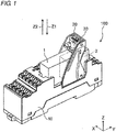
Fig. 1 is a perspective view showing a socket of a first embodiment of the invention when a relay is mounted in a socket body; -
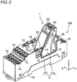
Fig. 2 is a perspective view showing the socket ofFig. 1 when the relay is removed from the socket body; -
Fig. 3 is a perspective view showing a holding lever of the socket ofFig. 1 ; -
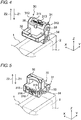
Fig. 4 is a perspective view showing a stopper, of the socket ofFig. 1 , at a restriction position; -
Fig. 5 is a perspective view showing the stopper, of the socket ofFig. 1 , turned from the restriction position toward a restriction release position by 90 degrees; -
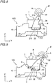
Fig. 6 is a diagram for illustrating movement when the relay is removed from the socket ofFig. 1 ; -
Fig. 7 is a plan view from a mounting direction of the relay for illustrating a positional relationship between the stopper of the socket and the relay ofFig. 1 ; -
Fig. 8 is a diagram followingFig. 6 for illustrating the middle of the movement when the relay is removed from the socket ofFig. 1 ; -
Fig. 9 is a diagram followingFig. 8 for illustrating the movement when the relay is removed from the socket ofFig. 1 ; -
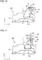
Fig. 10 is a side view of a socket of a second embodiment of the invention; and -
Fig. 11 is a side view of a socket of a third embodiment of the invention. - Hereinafter, an embodiment of the invention will be described with reference to the accompanying drawing. In the following description, words and terms representing certain directions and positions (words and terms including "up," "down," "right," and "left" are used, for example) are used if necessary; however, those words and terms are used to make the invention be understood easily with reference to the drawings, and the meanings of those words and terms do not limit the technical scope of the invention. Further, the following description is essentially just an example of the invention, and it is not intended to limit application targets or uses of the invention. In addition, the drawings are schematically drawn, and the ratios of the sizes are not the same as those of the actual sizes.
- A
socket 100 of a first embodiment of the invention has insulation properties, and, as shown inFig. 1 , thesocket 100 is equipped with: asocket body 10 which is in an approximate rectangular box shape and is mountable on a board; and aholding lever 20 rotatably supported on thesocket body 10. - The
socket 100 is a member configured to electrically connect terminals of a detachably mountedrelay 1, conductor parts of electric wires, and electrodes on the board with one another, and after thesocket 100 is assembled on the board, only therelay 1 is detachable to thesocket body 10 of thesocket 100, so that it is easy to repair or replace therelay 1. - Note that hereinafter the width direction of the
socket body 10 is the X direction, the longitudinal direction of thesocket body 10 is the Y direction, and the height direction of thesocket body 10 perpendicular to the X direction and the Y direction is the Z direction. - An example of the
relay 1 is an elongated rectangular box shaped relay for board-mount use and has acoil 2 at one internal end, in the longitudinal direction, of therelay 1 as shown inFig. 1 . Further, a plurality of terminals (not shown) are provided on the lower side surface, in the Y direction, of therelay 1. Note that therelay 1 is mounted in thesocket body 10 in the direction Z1 (directed from up to down) inFig. 1 and removed from thesocket body 10 in the direction Z2 (directed from down to up) inFig. 1 . That is, the mounting direction of therelay 1 with respect to thesocket body 10 is Z1, and the removing direction is Z2. - As shown in
Fig. 2 , thesocket body 10 has, on the upper side thereof in the Z direction, a mountingpart 11 on which therelay 1 is to be mounted. Themounting part 11 has a concave shape in which the right side in the X direction and the upper side in the Z direction are open, and extends in the direction (Y direction) in which thesocket body 10 extends. - On a bottom surface of the
mounting part 11, there are provided arelay mounting surface 111 extending in the longitudinal direction (Y direction) of thesocket body 10 andlever mounting surfaces 112 provided, in the direction in which therelay mounting surface 111 extends, so as to sandwich therelay mounting surface 111. Thelever mounting surfaces 112 are provided at positions (positions to which the straight line distances from the opening on the upper side in the Z direction is longer than the straight line distance to the relay mounting surface 111) lower than therelay mounting surface 111 and are disposed between the both ends of therelay mounting surface 111 in the longitudinal direction. - In the
relay mounting surface 111, there are provided a plurality ofterminal holes 12 into which a plurality of terminals 3 (shown inFig. 9 ) of therelay 1 are inserted and agroove portion 14 in which a removingrod 25 of the holding lever 20 (to be described later) is stored. Further, on thelever mounting surfaces 112, there is provided ashaft 13 to rotatably support theholding lever 20. - Note that, the position at which the
relay 1 is mounted on therelay mounting surface 111 shown inFig. 1 is defined as a mounting position of therelay 1. - The
terminal holes 12 are arranged depending on, for example, the type of therelay 1 to be mounted so as to be electrically connected to theterminals 3 of therelay 1. Theshaft 13 is disposed on the end part on the right side, in the Y direction, of the bottom surface of themounting part 11 and extends in the short side direction (X direction) of thesocket body 10. Theshaft 13 constitutes a first rotation shaft, being inserted in a lever-shaft receivingholes 26 in theholding lever 20. A shaft center of the first rotation shaft (the shaft 13) is perpendicular to the mounting direction Z1 and the removing direction Z2 of therelay 1 and functions as a rotation axis X1 (shown inFig. 3 ) of theholding lever 20. Thegroove portion 14 is disposed at an approximately central part of the bottom surface of themounting part 11 and extends along the X direction of thesocket body 10. - Further, in the periphery of the
mounting part 11 on the upper surface of thesocket body 10, there are provided a plurality ofterminal connection parts 15 in which conductor parts of electric wires are inserted and fixed. Theterminal connection parts 15 are electrically connected to theterminal holes 12 of the bottom surface of themounting part 11. - As shown in
Fig. 3 , theholding lever 20 has: a pair of support walls 21 (which is an example of the support) provided with a distance therebetween in the X direction to sandwich themounting part 11; and astopper 30 provided at the end parts, of the pair ofsupport walls 21, distal to thesocket body 10 in the removing direction Z2 of the relay 1 (the end parts are on the upper side in the Z direction). Each of the pair ofsupport walls 21 has a fan-like shape centered at the shaft center of each of the lever-shaft receiving holes 26 (to be described later). Further, thestopper 30 is supported on the pair ofsupport walls 21 to be rotatable within a predetermined angle range (for example, 90 degrees). - On the end parts on the upper side, in the Z direction, of the pair of
support walls 21, there are provided a connectingwall 22 to connect between the pair ofsupport walls 21 and stoppershaft receiving holes 23 in whichshafts 33 of the stopper 30 (to be described later) are inserted. Theconnecting wall 22 is provided on the right side, in the Y direction, of the upper ends of the pair ofsupport walls 21 so as to define a rotation range of thestopper 30. In addition, in the connectingwall 22, there is provided a secondengagement receiving part 27 with which asecond engagement protrusion 35 of thestopper 30 to be described later is releasably engaged. - Further, on the lower part, in the Z direction, than each of the stopper
shaft receiving holes 23 of the pair ofsupport walls 21, there is provided a firstengagement receiving part 24 with which each offirst engagement protrusions 34 of thestopper 30 to be described later is engaged. - On the left side, in the Y direction, on the end part (on the lower end part in the Z direction) proximal, in the removing direction Z2 of the
relay 1, to thesocket body 10 of the pair ofsupport walls 21, the removingrod 25 is provided, in the X direction, across between the pair ofsupport walls 21. That is, the removingrod 25 is disposed with a shaft center X2 thereof being approximately parallel to the rotation axis X1 of the holdinglever 20. Further, in the right side, in the Y direction, of the lower end part, in the Z direction, of each of the pair ofsupport walls 21, the lever-shaft receiving hole 26 is provided, and theshaft 13 of the mountingpart 11 of thesocket body 10 is inserted in each of the lever-shaft receiving holes 26. With this arrangement, the holdinglever 20 is rotatably supported on the mountingpart 11 of thesocket body 10. - That is, the holding
lever 20 is configured to rotate around the rotation axis X1, which is the shaft center of theshaft 13, between (i) a retreat position II (seeFig. 8 ) at which therelay 1 mounted at the mounting position can be removed and a holding position I (shown inFig. 1 andFig. 6 ) at which therelay 1 positioned at the mounting position can be held. - As shown in
Fig. 4 , thestopper 30 is constituted by a rectangular plate-shapedmain body 31 and anoperation part 32 provided on themain body 31. Thestopper 30 is disposed such that thestopper 30 covers, in a plan view from the mounting direction Z1, a center-of-gravity position P of the relay 1 (shown inFig. 7 ) when the holdinglever 20 is at the holding position I. In addition, thestopper 30 is disposed such that the holdinglever 20 does not interfere with the mounting or removal of therelay 1 when thestopper 30 is at the retreat position II. - The
main body 31 is mostly configured with a thick plate-like member and has the approximately cylinder-shapedshafts 33 each extending from each of the one end parts (the upper end parts in the Z direction inFig. 4 ) of the both side surfaces (the surfaces in the X direction inFig. 4 ). Theshafts 33 extend approximately parallel to theshaft 13 of the mountingpart 11 of thesocket body 10 and the removingrod 25 on the pair ofsupport walls 21. Further, theshafts 33 are inserted in the stoppershaft receiving holes 23 of the pair ofsupport walls 21 so that thestopper 30 is rotatably supported on the pair ofsupport walls 21. That is, theshafts 33 constitute a second rotation shaft, and the shaft center of the second rotation shaft is a rotation axis X3 (shown inFig. 3 ) of thestopper 30. - That is, the
stopper 30 is configured to rotate around the rotation axis X3, which is the shaft center of theshafts 33, between a restriction position III (shown inFig. 4 ) at which the movement of therelay 1 from the mountingpart 11 to the removing direction Z2 can be restricted and a restriction release position IV (seeFig. 8 ) at which the restriction of the movement of therelay 1 from the mountingpart 11 to the removing direction Z2 can be released. - Note that the restriction release position is the position at which the
stopper 30 at the restriction position III has been rotated by 180 degrees, and themain body 31 of thestopper 30 at the restriction position III and themain body 31 of thestopper 30 at the restriction release position IV are positioned on the same straight line perpendicular to the rotation axis X3 of thestopper 30. - Further, on the other end parts (the lower end parts in the Z direction in
Fig. 4 ) of the both side surfaces of themain body 31, thefirst engagement protrusions 34 are provided. Thefirst engagement protrusions 34 and theengagement receiving parts 24 of the pair ofsupport walls 21 can be locked (detachably held) with each other by snap fit and constitute a first locking mechanism to be used to lock thestopper 30 at the restriction position III and to release the locking of thestopper 30 at the restriction position III. - At the central part of the end face on the side on which the
shafts 33 of themain body 31 are provided, aflat part 311 is provided as shown inFig. 4 , and on the both ends of theflat part 311 in the longitudinal direction (the X direction inFig. 4 ), there are providedcurved parts 312 curved along the shape of theshafts 33. On theflat part 311, there is provided anarrow 313 to indicate the rotation direction to move thestopper 30 from the restriction position III to the restriction release position IV. - At the central part on the end face on the side on which the
engagement protrusions 34 of themain body 31 are provided, aflat part 314 is provided as shown inFig. 5 , and on the both ends of theflat part 314 in the longitudinal direction (the X direction inFig. 5 ), there are provided a pair of restrictionflat parts 315 protruding in the Y direction with respect to theflat part 314 at the restriction release position IV. On theflat part 314, there is provided anarrow 316 indicating the rotation direction for moving thestopper 30 from the restriction release position IV to the restriction position III. - Further, the pair of restriction
flat parts 315 is configured such that when the holdinglever 20 is at the holding position I and thestopper 30 is at the restriction position III, the restrictionflat parts 315 are in contact with therelay 1 in the vicinity of the both end parts of therelay 1 in the width direction (X direction) so as to restrict the movement of therelay 1 in the removing direction Z2. By providing the pair of restrictionflat parts 315 as described above, it is possible to restrict the movement of therelay 1 in the removing direction Z2 with a good balance. - The
operation part 32 is protrudingly provided on one plate surface of the main body 31 (the left side surface in the Y direction inFig. 4 ) and is disposed between theshafts 33 and thefirst engagement protrusions 34. Theoperation part 32 extends in the same direction as theshafts 33 extend. - Further, between the
flat part 311 and theoperation part 32 on the plate surface on which theoperation part 32 of themain body 31 is provided, thesecond engagement protrusion 35 is provided. Thesecond engagement protrusion 35 and theengagement receiving part 27 in the connectingwall 22 of the pair ofsupport walls 21 can be locked with each other by snap fit and constitute a second locking mechanism to lock thestopper 30 at the restriction release position IV and to release the locking of thestopper 30 at the restriction release position IV. - Next, with reference to
Fig. 6 to Fig. 9 , a description will be given to the movement when therelay 1 mounted on thesocket 100 is removed. - In the state shown in
Fig. 8 , by lowering therelay 1 in the mounting direction Z1 to press down the removingrod 25 and to rotate the holdinglever 20 around theshaft 13 from the retreat position II to the holding position I, therelay 1 is mounted on the mountingpart 11 of thesocket body 10 as shown inFig. 6 . After that, thestopper 30 is rotated around theshafts 33 from the restriction release position IV to the restriction position III. - At this time, the pair of restriction
flat parts 315 of thestopper 30 comes in contact with the both end parts in the width direction of the upper surface of therelay 1, and theflat part 314 between the pair of restrictionflat parts 315 of thestopper 30 covers, in the plan view in which therelay 1 is viewed from the mounting direction Z1, a center-of-gravity position P of therelay 1 as shown inFig. 7 . - Further, when the holding
lever 20 is at the holding position I, faces 211 facing the pair ofsupport walls 21 of thelever mounting surfaces 112 of the mountingpart 11 of thesocket body 10 are in contact with thelever mounting surfaces 112, and the removingrod 25 is between therelay 1 positioned at the mounting position and thelever mounting surfaces 112 of the mountingpart 11 of thesocket body 10. - First, as shown in
Fig. 8 , theoperation part 32 of thestopper 30 is pinched by fingers and operated such that thestopper 30 locked at the restriction position III by the first locking mechanism is rotated in the direction A of thearrow 313, whereby thestopper 30 is moved from the restriction position III to the restriction release position IV. In this operation, theoperation part 32 of thestopper 30 comes in contact with the connectingwall 22 of the pair ofsupport walls 21, so that the rotation of thestopper 30 in the direction A of thearrow 313 is restricted and so that thestopper 30 is locked at the restriction release position IV by the second locking mechanism. - After the
stopper 30 moves to the restriction release position IV and get locked at the restriction release position IV by the second locking mechanism, the holdinglever 20 is rotated in the direction A of thearrow 313 as shown inFig. 9 and is thus moved from the holding position I to the retreat position II. In this operation, the removingrod 25 between the lower surface of therelay 1 and the mountingpart 11 of thesocket body 10 pushes therelay 1 in the removing direction Z2 along with the rotational movement of the holdinglever 20 and moves therelay 1. By this operation, theterminals 3 of therelay 1 are pulled out from the terminal holes 12, and therelay 1 is removed from the mountingpart 11 of thesocket body 10. - Further, when the holding
lever 20 is at the retreat position, a gap S is formed between thefaces 211 of the pair ofsupport walls 21 facing thelever mounting surfaces 112 of the mountingpart 11 of thesocket body 10 and the lever mounting surfaces 112. - In a conventional socket in which a relay is detachable, the stopper is at the end part away from the center-of-gravity position of the relay in the plan view from the mounting direction; therefore, the force for holding the relay at the mounting position is so weak that the relay may unintentionally fall off from the mounting position when a vibration or impact is applied to the conventional socket.
- The
socket 100 of the first embodiment is equipped with the holdinglever 20, and the holdinglever 20 has thestopper 30 which is movable between (i) the restriction position III at which therelay 1 cannot be removed and (ii) the restriction release position IV at which the relay is released; and when thestopper 30 is at the restriction position III such that thestopper 30 covers, in the plan view from the mounting direction Z1, the center-of-gravity position P of therelay 1, therelay 1 positioned at the mounting position can be held. This arrangement increases the force for holding therelay 1 at the mounting position, whereby it is possible to prevent therelay 1 from unintentionally falling off from the mounting part of thesocket body 10. - Further, the holding
lever 20 is supported on the mountingpart 11 of thesocket body 10 and can rotatably move, around the rotation axis perpendicular to the mounting direction Z1 and the removing direction Z2, between the retreat position and the holding position. Further, when the holdinglever 20 is at the holding position, thestopper 30 can move between (i) the restriction position at which it is possible to restrict the movement of therelay 1 positioned at the mounting position from the mountingpart 11 to the removing direction Z2 and (ii) the restriction release position at which it is possible to release the restriction of the movement of therelay 1 positioned at the mounting position from the mountingpart 11 to the removing direction Z2. This arrangement makes it easy to mount therelay 1 on the mountingpart 11 of thesocket body 10 and to remove therelay 1 positioned at the mounting position from the mountingpart 11 of thesocket body 10. - Further, the holding
lever 20 has the first lock mechanism to lock thestopper 30 at the restriction position. This arrangement can reliably prevent therelay 1 from unintendedly falling off from the mounting part of thesocket body 10. - Further, the first lock mechanism is configured with the
first engagement protrusions 34 provided on thestopper 30 and theengagement receiving parts 24 in the pair ofsupport walls 21, and thefirst engagement protrusions 34 and theengagement receiving parts 24 are locked with each other by snap fit. This arrangement makes it easy to visually recognize that thestopper 30 is at the restriction position III, whereby the operability is improved. - Further, the pair of
support walls 21 is provided as supports to sandwich the mountingpart 11, the pair ofsupport walls 21 can rotationally move around theshaft 13 between the retreat position and the holding position, and thestopper 30 can rotationally moves around theshafts 33 between the restriction position and the restriction release position. This arrangement can reduce the operation range of the holdinglever 20 for mounting and removing therelay 1 on and from thesocket body 10. - Further, the pair of
support walls 21 has the removingrod 25 which is disposed between the pair ofsupport walls 21 and is positioned between therelay 1 positioned at the mounting position and thesocket body 10 when the holdinglever 20 is at the holding position. This arrangement make it easy to remove therelay 1 positioned at the mounting position from the mountingpart 11 of thesocket body 10. - Note that the
stopper 30 only has to be disposed such that the end face of themain body 31 on which theengagement protrusions 34 are provided covers, in the plan view from the mounting direction Z1, the center-of-gravity position P of therelay 1 when the holdinglever 20 is at the holding position and thestopper 30 is at the restriction position. That is, theflat part 314 of thestopper 30 does not necessarily have to cover the center-of-gravity position P of therelay 1 in the plan view from the mounting direction Z1, and instead thestopper 30 may be disposed such that the restrictionflat parts 315 covers the center-of-gravity position P of therelay 1. - The center-of-gravity position P of the
relay 1 depends on the type or the like of therelay 1; and in the case of therelay 1 having therein thecoil 2, the center of gravity P is deviated from the central part in the longitudinal direction of therelay 1 toward thecoil 2 side. In addition, regarding the terminals protruding from therelay 1 having therein thecoil 2, more of terminals are on the side on which thecoil 2 is not disposed than on the side on which thecoil 2 is disposed. Generally, the part having a smaller number of terminals tends to easily come out than the part having a greater number of terminals. For this reason, in the case of therelay 1 having therein thecoil 2, by configuring such that thestopper 30 is positioned on the part having a smaller number of the terminals protruding from therelay 1, it is possible to prevent therelay 1 from unintentionally falling off from the mounting part of thesocket body 10. - In the first embodiment, the holding
lever 20 is rotatably supported on the mountingpart 11 of thesocket body 10, but the present invention is not limited thereto. The holding lever only has to be movable between the retreat position and the holding position, and, for example, the holding lever may be configured to be slidingly moved along the longitudinal direction of the socket body between the retreat position and the holding position. - Further, the pair of
support walls 21 is used as the support, but the support is not limited thereto. The support only has to be a member which extends from the mounting part in the removing direction of the relay and can support the stopper, and, for example, the support may be configured with one or more than three support walls or with one or more rods. - Further, the
stopper 30 is configured such that the pair of restrictionflat parts 315 is in contact with therelay 1 in the vicinity of the both end parts of the width direction (X direction) of therelay 1 so as to restrict the movement of therelay 1 in the removing direction Z2 when the holdinglever 20 is at the holding position I and thestopper 30 is at the restriction position III, but the stopper is not limited thereto. The stopper only has to restrict the movement of the relay in the removing direction with the pair of restriction flat parts so as to keep the electrical connections between the terminals of the relay and the terminal holes, and, for example, the pair of restriction flat parts and the relay may not be in contact with each other. - Further, the pair of restriction
flat parts 315 of thestopper 30 is provided in the vicinity of the both end parts in the width direction of therelay 1, but are not limited thereto. For example, the pair of restrictionflat parts 315 of thestopper 30 may be made to be in contact only with the vicinity of the central part in the width direction of the relay; or alternatively, the whole of the end face, of the main body, on the side on which the engagement protrusion is provided may be made a restriction flat part. - The removing
rod 25 does not only have to be one, and a plurality of removingrods 25 may be provided. Further, the shaft center X2 of the removingrod 25 does not necessarily have to be disposed parallel to the rotation axis X1 of the holdinglever 20. The removing rod can be arbitrarily disposed as long as the removing rod can move the relay in the removing direction from the mounting position along with the movement of the holding lever from the holding position to the retreat position. - If possible, a shaft functioning as the rotation shaft of the holding lever may be provided on the pair of support walls of the holding lever, and a relay-shaft receiving hole may be provided in the relay mounting surface of the socket body. In a similar way, a shaft functioning as the rotation shaft of the stopper may be provided on the pair of support walls of the holding lever, and a stopper shaft receiving hole may be provided in the stopper.
- Further, it may be possible to omit the locking mechanism to lock the
stopper 30 at the restriction position and the restriction release position and to omit the removingrod 25 of the pair ofsupport walls 21. - As shown in
Fig. 10 , asocket 200 of a second embodiment is different from thesocket 100 of the first embodiment in that thesocket 200 has astopper 130 which can slidingly move between the restriction position III and the restriction release position IV. - Note that in the second embodiment, the same parts as in the first embodiment are assigned the same reference numerals and are not described again.
- The
stopper 130 is provided on the opposing inner surfaces of the pair ofsupport walls 21, is supported inguide grooves 131 as an example of a guide part which guides thestopper 130 in the Y direction, and can slidingly move between the restriction position III and the restriction release position IV. - As described above, the stopper does not necessarily have to rotationally move between the restriction position and the restriction release position, and instead the stopper may be provided so as to slidingly move between the restriction position and the restriction release position. Therefore, the socket can be designed in accordance with application or the like, and the flexibility in designing sockets can be widened.
- As shown in
Fig. 11 , asocket 300 of a third embodiment is different from thesocket 100 of the first embodiment in that thesocket 300 has astopper 230 which can rotationally move between the restriction position III and the restriction release position IV. - Note that in the third embodiment, the same parts as in the first embodiment are assigned the same reference numerals and are not described again.
- The
stopper 230 is configured with: ascrew shaft 231 which covers, in the plan view from the mounting direction Z1 of therelay 1, the center-of-gravity position P of therelay 1, and extends in the Z direction; and ascrew head 232 provided on the upper end, in the Z direction, of thescrew shaft 231. Regarding thestopper 230, when thescrew head 232 is operated by fingers pinching thescrew head 232 such that thescrew shaft 231 is normally or reversely rotated around a rotation axis X4 extending in the mounting direction Z1 of therelay 1, thetop end 233 moves between the restriction position III and the restriction release position VI. - The stopper does not necessarily have to rotationally move around the rotation shaft disposed between the pair of support walls between the restriction position and the restriction release position as described above, and instead the stopper may be provided to rotationally move, around a rotation axis extending in the mounting direction of the relay, between the restriction position and the restriction release position. Therefore, the socket can be designed to meet the application and the like, and the flexibility in designing sockets can be widened.
- Note that on the top end of the
screw shaft 231, there may be provided a guard portion having a diameter larger than the diameter of thescrew shaft 231. - It is a matter of course that the components described in the above embodiments may be appropriately combined with one another or maybe appropriately chosen, replaced, or removed.
- A socket of the invention includes: a socket body having a mounting part on which a relay is to be mounted in a mounting direction; and a holding lever supported on the mounting part of the socket body and configured to hold the relay mounted at a mounting position of the mounting part. The holding lever has: a support extending from the mounting part of the socket body in a removing direction opposite to the mounting direction; and a stopper provided on an end part of the support distal to the socket body in the removing direction and configured to restrict movement, of the relay positioned at the mounting position, in the removing direction. The stopper is provided on the support and configured to move between a restriction position at which the stopper restricts movement of the relay, positioned at the mounting position, in the removing direction from the mounting part and a restriction release position at which the stopper releases the restriction of the movement of the relay, positioned at the mounting position, in the removing direction from the mounting part. The holding lever is supported on the mounting part and configured to move between a retreat position at which, when the stopper is positioned at the restriction release position, a relay can be mounted at the mounting position of the mounting part and the relay mounted at mounting position can be removed and a holding position at which the relay positioned at the mounting position can be held when the stopper is positioned at the restriction position such that the stopper covers, in a plan view from the mounting direction, a center-of-gravity position of the relay.
- A socket of the invention has: a stopper configured to move between a restriction position at which a relay cannot be removed and a restriction release position at which the relay is released; and a holding lever configured to hold the relay positioned at a mounting position when the stopper is positioned at the restriction position such that the stopper covers, in a plan view from a mounting direction, a center-of-gravity position of the relay. This arrangement can increase the force for holding the relay at the mounting position and can prevent the relay from unintentionally falling off from the mounting part of the socket body.
- In a socket of an embodiment, the support is supported on the mounting part of the socket body and is configured to rotationally move, around a shaft perpendicularly crossing the mounting direction and the removing direction, between the retreat position and the holding position.
- According to the above embodiment, the relay can be easily mounted on the mounting part of the socket body, and the relay positioned at the mounting position can be easily removed from the mounting part of the socket body.
- In a socket of an embodiment, the support is a pair of support walls provided to sandwich the mounting part, and the pair of support walls has the perpendicularly crossing shaft which is provided at an end part proximal, in the removing direction, to the socket body and which extends in a direction crossing each of the pair of support walls, and the pair of support walls is supported on the mounting part to be rotatable around the perpendicularly crossing shaft between the retreat position and the holding position. The stopper has a rotation shaft which is provided at an end part distal, in the removing direction, to the socket body and which extends in such a direction that the rotation shaft crosses each of the pair of support walls, and is supported on the pair of support walls to be rotatable, around the rotation shaft, between the restriction position and the restriction release position.
- According to the above embodiment, it is possible to reduce the operation range of the holding lever for mounting and removing the relay on and from the socket body.
- In a socket of an embodiment, the support has a guide part configured to guide the stopper in a direction perpendicular to the mounting direction and the removing direction, and the stopper is supported on the guide part to be slidingly movable between the restriction position and the restriction release position.
- According to the above embodiment, it is possible to design the socket in accordance with application or the like and thus to widen the flexibility in designing sockets.
- In a socket of an embodiment, the stopper has: a rotation axis extending in the mounting direction, and a screw shaft whose one end is moved between the restriction position and the restriction release position when the screw shaft is normally or reversely rotated around the rotation axis.
- According to the above embodiment, it is possible to design the socket in accordance with application or the like and thus to widen the flexibility in designing sockets.
- In a socket of an embodiment, the holding lever has a locking mechanism to lock the stopper at the restriction position.
- According to the above embodiment, it is possible to reliably prevent the relay from unintentionally falling off from the mounting part of the socket body.
- In a socket of an embodiment, the locking mechanism is configured with: an engagement protrusion provided on any one of the stopper and the support; and an engagement receiving part which is provided on the other of the stopper and the support and with which the engagement protrusion can be locked, where the engagement protrusion and the engagement receiving part are detachably locked with each other.
- The above embodiment makes it easier to visually recognize that the stopper is positioned at the restriction position, and the operability is thus improved.
- A socket of the invention is applicable to, for example, a socket for wiring a relay for board-mount use to a board.
Claims (7)
- A socket comprising:a socket body including a mounting part on which a relay is to be mounted in a mounting direction; anda holding lever supported on the mounting part of the socket body and configured to hold the relay mounted at a mounting position of the mounting part,
whereinthe holding lever includes:a support extending from the mounting part of the socket body in a removing direction opposite to the mounting direction; anda stopper provided on an end part of the support distal to the socket body in the removing direction and configured to restrict movement of the relay, positioned at the mounting position, in the removing direction,the stopper is provided on the support and configured to move between a restriction position and a restriction release position, wherein at the restriction position, the stopper restricts movement of the relay, positioned at the mounting position, in the removing direction from the mounting part, and wherein at the restriction release position, the stopper releases the restriction of the movement of the relay, positioned at the mounting position, in the removing direction from the mounting part, andthe holding lever is supported on the mounting part and configured to move between a retreat position and a holding position, wherein at the retreat position, when the stopper is positioned at the restriction release position, a relay can be mounted at the mounting position of the mounting part and the relay mounted at mounting position can be removed, and wherein at the holding position, the relay positioned at the mounting position can be held when the stopper is positioned at the restriction position such that the stopper covers, in a plan view from the mounting direction, a center-of-gravity position of the relay. - The socket according to claim 1, wherein the support is supported on the mounting part of the socket body and is configured to rotationally move, around a shaft perpendicularly crossing the mounting direction and the removing direction, between the retreat position and the holding position.
- The socket according to claim 1 or 2, wherein the support is a pair of support walls provided to sandwich the mounting part,
the pair of support walls includes the perpendicularly crossing shaft which is provided at an end part proximal, in the removing direction, to the socket body and which extends in a direction crossing each of the pair of support walls, and the pair of support walls is supported on the mounting part to be rotatable around the perpendicularly crossing shaft between the retreat position and the holding position, and
the stopper includes a rotation shaft which is provided at an end part distal, in the removing direction, to the socket body and which extends in such a direction that the rotation shaft crosses each of the pair of support walls, and is supported on the pair of support walls to be rotatable, around the rotation shaft, between the restriction position and the restriction release position. - The socket according to any of claims 1 to 3, wherein the support includes a guide part configured to guide the stopper in a direction perpendicular to the mounting direction and the removing direction, and
the stopper is supported on the guide part to be slidingly movable between the restriction position and the restriction release position. - The socket according to any of claims 1 to 4, wherein the stopper includes:a rotation axis extending in the mounting direction, anda screw shaft whose one end is moved between the restriction position and the restriction release position when the screw shaft is normally or reversely rotated around the rotation axis.
- The socket according to any one of claims 1 to 5, wherein the holding lever includes a locking mechanism to lock the stopper at the restriction position.
- The socket according to claim 6, wherein the locking mechanism is configured with:an engagement protrusion provided on any one of the stopper and the support; andan engagement receiving part which is provided on the other of the stopper and the support and with which the engagement protrusion can be locked, andwherein the engagement protrusion and the engagement receiving part are detachably locked with each other.
Applications Claiming Priority (1)
| Application Number | Priority Date | Filing Date | Title |
|---|---|---|---|
| JP2016139527A JP6702048B2 (en) | 2016-07-14 | 2016-07-14 | socket |
Publications (2)
| Publication Number | Publication Date |
|---|---|
| EP3270465A1 true EP3270465A1 (en) | 2018-01-17 |
| EP3270465B1 EP3270465B1 (en) | 2018-10-03 |
Family
ID=59101309
Family Applications (1)
| Application Number | Title | Priority Date | Filing Date |
|---|---|---|---|
| EP17176888.0A Active EP3270465B1 (en) | 2016-07-14 | 2017-06-20 | Socket |
Country Status (4)
| Country | Link |
|---|---|
| US (1) | US9966698B2 (en) |
| EP (1) | EP3270465B1 (en) |
| JP (1) | JP6702048B2 (en) |
| CN (1) | CN107623226B (en) |
Cited By (2)
| Publication number | Priority date | Publication date | Assignee | Title |
|---|---|---|---|---|
| WO2021116130A1 (en) * | 2019-12-09 | 2021-06-17 | Phoenix Contact Gmbh & Co.Kg | Electric component, in particular a terminal block, comprising a plug socket for receiving a receiving component |
| US12712298B2 (en) | 2019-12-09 | 2026-08-18 | Phoenix Contact Gmbh & Co. Kg | Electric component, in particular terminal block, comprising a socket for receiving a receiving component |
Families Citing this family (5)
| Publication number | Priority date | Publication date | Assignee | Title |
|---|---|---|---|---|
| JP1623418S (en) * | 2018-03-14 | 2019-02-04 | ||
| USD923586S1 (en) * | 2018-12-17 | 2021-06-29 | Omron Corporation | Terminal block |
| JP7703949B2 (en) * | 2021-08-27 | 2025-07-08 | オムロン株式会社 | socket |
| JP7786229B2 (en) * | 2022-01-31 | 2025-12-16 | オムロン株式会社 | socket |
| CN220209402U (en) | 2023-05-12 | 2023-12-19 | 江苏佰瑞普智能科技有限公司 | Safety door socket |
Citations (3)
| Publication number | Priority date | Publication date | Assignee | Title |
|---|---|---|---|---|
| EP1052731A2 (en) | 1999-05-14 | 2000-11-15 | Weidmüller Interface GmbH & Co. | Terminals for side by side mounting |
| WO2013132808A1 (en) * | 2012-03-05 | 2013-09-12 | タイコエレクトロニクスジャパン合同会社 | Lever-type connector |
| DE102013222959A1 (en) * | 2013-11-12 | 2015-05-13 | Robert Bosch Gmbh | Electric plug and plug system with a lever for closing a plug connection |
Family Cites Families (26)
| Publication number | Priority date | Publication date | Assignee | Title |
|---|---|---|---|---|
| US2449646A (en) * | 1945-11-23 | 1948-09-21 | Zenith Radio Corp | Vacuum tube lock |
| US2539581A (en) * | 1946-01-08 | 1951-01-30 | Lawrence T Holden | Adjustable spring hold-down for radio tubes |
| US2575601A (en) * | 1947-08-20 | 1951-11-20 | Edward F Staver | Guard for vacuum tubes |
| US2673334A (en) * | 1951-10-03 | 1954-03-23 | Gen Motors Corp | Retainer spring |
| US3061761A (en) * | 1958-06-10 | 1962-10-30 | Gen Atronics Corp | Circuit pack assembly |
| US3008115A (en) * | 1959-06-24 | 1961-11-07 | George W Oakes | Electrical plug and electing device therefor |
| US3918786A (en) * | 1974-06-17 | 1975-11-11 | Esco Mfg Co | Electrical connector apparatus |
| US4501455A (en) * | 1982-01-15 | 1985-02-26 | Honeywell Inc. | Locking and extraction mechanism for rack mounted components |
| US4531795A (en) * | 1983-03-01 | 1985-07-30 | Aries Electronics, Inc. | Ejector socket for DIP jumpers |
| US5057029A (en) * | 1990-05-31 | 1991-10-15 | Thomas & Betts Corporation | Electrical eject header |
| JP2568730Y2 (en) * | 1992-12-24 | 1998-04-15 | 住友電装株式会社 | Lever connector |
| US6164991A (en) * | 1997-06-27 | 2000-12-26 | Yazaki Corporation | Slidably attaching type connector |
| JP3302619B2 (en) * | 1997-07-01 | 2002-07-15 | 矢崎総業株式会社 | Lever mating connector |
| JP4168483B2 (en) * | 1998-05-29 | 2008-10-22 | モレックス インコーポレーテッド | Wire relay method and electrical connector structure |
| US6629852B2 (en) * | 2001-03-15 | 2003-10-07 | Omron Corporation | Relay socket |
| JP2003272767A (en) * | 2002-03-15 | 2003-09-26 | Idec Izumi Corp | Relay socket |
| US7052294B1 (en) * | 2005-04-15 | 2006-05-30 | J.S.T. Corporation | Electrical connector with a locking mechanism |
| WO2008015817A1 (en) * | 2006-07-31 | 2008-02-07 | Mitsumi Electric Co., Ltd. | Connector for connecting electronic component |
| CN201112654Y (en) * | 2007-07-16 | 2008-09-10 | 富士康(昆山)电脑接插件有限公司 | card edge connector |
| KR101002605B1 (en) * | 2008-10-14 | 2010-12-20 | 이문재 | Relay socket with improved relay identification |
| US8083531B1 (en) * | 2008-12-31 | 2011-12-27 | Manour Ourasanah | Power connector |
| CN201378549Y (en) * | 2009-03-26 | 2010-01-06 | 天水二一三电器配件厂 | Relay socket |
| CN101867110B (en) * | 2010-02-21 | 2012-06-13 | 厦门宏远达电器有限公司 | Electric connection terminal and relay socket thereof |
| US9024486B2 (en) * | 2010-08-20 | 2015-05-05 | Rockwell Automation Technologies, Inc. | Adaptable automation control module with integrated power bus distributor |
| US8771006B1 (en) * | 2012-01-30 | 2014-07-08 | Sidney A. Blinson | Plug removal tool and method |
| DE102012105509B4 (en) * | 2012-06-25 | 2018-04-05 | Wago Verwaltungsgesellschaft Mbh | Electronic equipment housing |
-
2016
- 2016-07-14 JP JP2016139527A patent/JP6702048B2/en active Active
-
2017
- 2017-06-13 CN CN201710441492.1A patent/CN107623226B/en active Active
- 2017-06-16 US US15/624,909 patent/US9966698B2/en active Active
- 2017-06-20 EP EP17176888.0A patent/EP3270465B1/en active Active
Patent Citations (3)
| Publication number | Priority date | Publication date | Assignee | Title |
|---|---|---|---|---|
| EP1052731A2 (en) | 1999-05-14 | 2000-11-15 | Weidmüller Interface GmbH & Co. | Terminals for side by side mounting |
| WO2013132808A1 (en) * | 2012-03-05 | 2013-09-12 | タイコエレクトロニクスジャパン合同会社 | Lever-type connector |
| DE102013222959A1 (en) * | 2013-11-12 | 2015-05-13 | Robert Bosch Gmbh | Electric plug and plug system with a lever for closing a plug connection |
Cited By (2)
| Publication number | Priority date | Publication date | Assignee | Title |
|---|---|---|---|---|
| WO2021116130A1 (en) * | 2019-12-09 | 2021-06-17 | Phoenix Contact Gmbh & Co.Kg | Electric component, in particular a terminal block, comprising a plug socket for receiving a receiving component |
| US12712298B2 (en) | 2019-12-09 | 2026-08-18 | Phoenix Contact Gmbh & Co. Kg | Electric component, in particular terminal block, comprising a socket for receiving a receiving component |
Also Published As
| Publication number | Publication date |
|---|---|
| CN107623226A (en) | 2018-01-23 |
| US9966698B2 (en) | 2018-05-08 |
| JP6702048B2 (en) | 2020-05-27 |
| US20180019543A1 (en) | 2018-01-18 |
| EP3270465B1 (en) | 2018-10-03 |
| JP2018010810A (en) | 2018-01-18 |
| CN107623226B (en) | 2019-03-19 |
Similar Documents
| Publication | Publication Date | Title |
|---|---|---|
| EP3270465B1 (en) | Socket | |
| ES2885826T3 (en) | Assemblies, systems and methods of mounting devices on DIN rail, including locking mechanisms | |
| JP5090432B2 (en) | Fitting guide part for electric connector and electric connector device having the same | |
| US9882310B2 (en) | Connection structure and apparatus unit | |
| CN110277278B (en) | Socket with improved structure | |
| US9640342B2 (en) | System comprising electronics housing and grounding contact assembly | |
| JP5275133B2 (en) | Connector module | |
| EP2865252B1 (en) | Electronics device housing | |
| JP7021572B2 (en) | socket | |
| JP6992621B2 (en) | Connector and socket | |
| EP3333984A1 (en) | Electric connector | |
| US20170005434A1 (en) | Connector and connector device | |
| JP6929821B2 (en) | Electrical connector | |
| US7806719B2 (en) | Module having terminals for actuators and/or sensors | |
| EP3264532A1 (en) | Terminal connecting mechanism and switch | |
| CN111600157B (en) | Electrical connector | |
| EP2894730A1 (en) | Plug conversion adapter | |
| US9325111B2 (en) | Electrical center and connector assembly system | |
| CN110235216B (en) | Trigger switch | |
| US20150008109A1 (en) | Electronic housing for switching devices, in particular for low-voltage switching devices | |
| US20200280147A1 (en) | Connector terminal and connector | |
| DE112017007260B4 (en) | TRIGGER SWITCH | |
| JP6953995B2 (en) | Switch mounting structure | |
| US8253019B2 (en) | Cable routing device and unit for telecommunication and data technology | |
| EP3176891B1 (en) | Mounting assembly and kit for a mounting assembly |
Legal Events
| Date | Code | Title | Description |
|---|---|---|---|
| PUAI | Public reference made under article 153(3) epc to a published international application that has entered the european phase |
Free format text: ORIGINAL CODE: 0009012 |
|
| STAA | Information on the status of an ep patent application or granted ep patent |
Free format text: STATUS: REQUEST FOR EXAMINATION WAS MADE |
|
| 17P | Request for examination filed |
Effective date: 20170620 |
|
| AK | Designated contracting states |
Kind code of ref document: A1 Designated state(s): AL AT BE BG CH CY CZ DE DK EE ES FI FR GB GR HR HU IE IS IT LI LT LU LV MC MK MT NL NO PL PT RO RS SE SI SK SM TR |
|
| AX | Request for extension of the european patent |
Extension state: BA ME |
|
| GRAP | Despatch of communication of intention to grant a patent |
Free format text: ORIGINAL CODE: EPIDOSNIGR1 |
|
| STAA | Information on the status of an ep patent application or granted ep patent |
Free format text: STATUS: GRANT OF PATENT IS INTENDED |
|
| RIC1 | Information provided on ipc code assigned before grant |
Ipc: H01R 9/26 20060101AFI20180416BHEP Ipc: H01R 13/629 20060101ALI20180416BHEP |
|
| INTG | Intention to grant announced |
Effective date: 20180504 |
|
| GRAS | Grant fee paid |
Free format text: ORIGINAL CODE: EPIDOSNIGR3 |
|
| GRAA | (expected) grant |
Free format text: ORIGINAL CODE: 0009210 |
|
| STAA | Information on the status of an ep patent application or granted ep patent |
Free format text: STATUS: THE PATENT HAS BEEN GRANTED |
|
| AK | Designated contracting states |
Kind code of ref document: B1 Designated state(s): AL AT BE BG CH CY CZ DE DK EE ES FI FR GB GR HR HU IE IS IT LI LT LU LV MC MK MT NL NO PL PT RO RS SE SI SK SM TR |
|
| REG | Reference to a national code |
Ref country code: GB Ref legal event code: FG4D |
|
| REG | Reference to a national code |
Ref country code: CH Ref legal event code: EP Ref country code: AT Ref legal event code: REF Ref document number: 1049644 Country of ref document: AT Kind code of ref document: T Effective date: 20181015 |
|
| REG | Reference to a national code |
Ref country code: IE Ref legal event code: FG4D Ref country code: DE Ref legal event code: R096 Ref document number: 602017000576 Country of ref document: DE |
|
| REG | Reference to a national code |
Ref country code: NL Ref legal event code: MP Effective date: 20181003 |
|
| REG | Reference to a national code |
Ref country code: LT Ref legal event code: MG4D |
|
| REG | Reference to a national code |
Ref country code: AT Ref legal event code: MK05 Ref document number: 1049644 Country of ref document: AT Kind code of ref document: T Effective date: 20181003 |
|
| PG25 | Lapsed in a contracting state [announced via postgrant information from national office to epo] |
Ref country code: NL Free format text: LAPSE BECAUSE OF FAILURE TO SUBMIT A TRANSLATION OF THE DESCRIPTION OR TO PAY THE FEE WITHIN THE PRESCRIBED TIME-LIMIT Effective date: 20181003 |
|
| PG25 | Lapsed in a contracting state [announced via postgrant information from national office to epo] |
Ref country code: BG Free format text: LAPSE BECAUSE OF FAILURE TO SUBMIT A TRANSLATION OF THE DESCRIPTION OR TO PAY THE FEE WITHIN THE PRESCRIBED TIME-LIMIT Effective date: 20190103 Ref country code: NO Free format text: LAPSE BECAUSE OF FAILURE TO SUBMIT A TRANSLATION OF THE DESCRIPTION OR TO PAY THE FEE WITHIN THE PRESCRIBED TIME-LIMIT Effective date: 20190103 Ref country code: IS Free format text: LAPSE BECAUSE OF FAILURE TO SUBMIT A TRANSLATION OF THE DESCRIPTION OR TO PAY THE FEE WITHIN THE PRESCRIBED TIME-LIMIT Effective date: 20190203 Ref country code: FI Free format text: LAPSE BECAUSE OF FAILURE TO SUBMIT A TRANSLATION OF THE DESCRIPTION OR TO PAY THE FEE WITHIN THE PRESCRIBED TIME-LIMIT Effective date: 20181003 Ref country code: LT Free format text: LAPSE BECAUSE OF FAILURE TO SUBMIT A TRANSLATION OF THE DESCRIPTION OR TO PAY THE FEE WITHIN THE PRESCRIBED TIME-LIMIT Effective date: 20181003 Ref country code: AT Free format text: LAPSE BECAUSE OF FAILURE TO SUBMIT A TRANSLATION OF THE DESCRIPTION OR TO PAY THE FEE WITHIN THE PRESCRIBED TIME-LIMIT Effective date: 20181003 Ref country code: ES Free format text: LAPSE BECAUSE OF FAILURE TO SUBMIT A TRANSLATION OF THE DESCRIPTION OR TO PAY THE FEE WITHIN THE PRESCRIBED TIME-LIMIT Effective date: 20181003 Ref country code: CZ Free format text: LAPSE BECAUSE OF FAILURE TO SUBMIT A TRANSLATION OF THE DESCRIPTION OR TO PAY THE FEE WITHIN THE PRESCRIBED TIME-LIMIT Effective date: 20181003 Ref country code: LV Free format text: LAPSE BECAUSE OF FAILURE TO SUBMIT A TRANSLATION OF THE DESCRIPTION OR TO PAY THE FEE WITHIN THE PRESCRIBED TIME-LIMIT Effective date: 20181003 Ref country code: PL Free format text: LAPSE BECAUSE OF FAILURE TO SUBMIT A TRANSLATION OF THE DESCRIPTION OR TO PAY THE FEE WITHIN THE PRESCRIBED TIME-LIMIT Effective date: 20181003 Ref country code: HR Free format text: LAPSE BECAUSE OF FAILURE TO SUBMIT A TRANSLATION OF THE DESCRIPTION OR TO PAY THE FEE WITHIN THE PRESCRIBED TIME-LIMIT Effective date: 20181003 |
|
| PG25 | Lapsed in a contracting state [announced via postgrant information from national office to epo] |
Ref country code: PT Free format text: LAPSE BECAUSE OF FAILURE TO SUBMIT A TRANSLATION OF THE DESCRIPTION OR TO PAY THE FEE WITHIN THE PRESCRIBED TIME-LIMIT Effective date: 20190203 Ref country code: SE Free format text: LAPSE BECAUSE OF FAILURE TO SUBMIT A TRANSLATION OF THE DESCRIPTION OR TO PAY THE FEE WITHIN THE PRESCRIBED TIME-LIMIT Effective date: 20181003 Ref country code: RS Free format text: LAPSE BECAUSE OF FAILURE TO SUBMIT A TRANSLATION OF THE DESCRIPTION OR TO PAY THE FEE WITHIN THE PRESCRIBED TIME-LIMIT Effective date: 20181003 Ref country code: AL Free format text: LAPSE BECAUSE OF FAILURE TO SUBMIT A TRANSLATION OF THE DESCRIPTION OR TO PAY THE FEE WITHIN THE PRESCRIBED TIME-LIMIT Effective date: 20181003 Ref country code: GR Free format text: LAPSE BECAUSE OF FAILURE TO SUBMIT A TRANSLATION OF THE DESCRIPTION OR TO PAY THE FEE WITHIN THE PRESCRIBED TIME-LIMIT Effective date: 20190104 |
|
| REG | Reference to a national code |
Ref country code: DE Ref legal event code: R097 Ref document number: 602017000576 Country of ref document: DE |
|
| PG25 | Lapsed in a contracting state [announced via postgrant information from national office to epo] |
Ref country code: DK Free format text: LAPSE BECAUSE OF FAILURE TO SUBMIT A TRANSLATION OF THE DESCRIPTION OR TO PAY THE FEE WITHIN THE PRESCRIBED TIME-LIMIT Effective date: 20181003 Ref country code: IT Free format text: LAPSE BECAUSE OF FAILURE TO SUBMIT A TRANSLATION OF THE DESCRIPTION OR TO PAY THE FEE WITHIN THE PRESCRIBED TIME-LIMIT Effective date: 20181003 |
|
| PLBE | No opposition filed within time limit |
Free format text: ORIGINAL CODE: 0009261 |
|
| STAA | Information on the status of an ep patent application or granted ep patent |
Free format text: STATUS: NO OPPOSITION FILED WITHIN TIME LIMIT |
|
| PG25 | Lapsed in a contracting state [announced via postgrant information from national office to epo] |
Ref country code: SM Free format text: LAPSE BECAUSE OF FAILURE TO SUBMIT A TRANSLATION OF THE DESCRIPTION OR TO PAY THE FEE WITHIN THE PRESCRIBED TIME-LIMIT Effective date: 20181003 Ref country code: EE Free format text: LAPSE BECAUSE OF FAILURE TO SUBMIT A TRANSLATION OF THE DESCRIPTION OR TO PAY THE FEE WITHIN THE PRESCRIBED TIME-LIMIT Effective date: 20181003 Ref country code: SK Free format text: LAPSE BECAUSE OF FAILURE TO SUBMIT A TRANSLATION OF THE DESCRIPTION OR TO PAY THE FEE WITHIN THE PRESCRIBED TIME-LIMIT Effective date: 20181003 Ref country code: RO Free format text: LAPSE BECAUSE OF FAILURE TO SUBMIT A TRANSLATION OF THE DESCRIPTION OR TO PAY THE FEE WITHIN THE PRESCRIBED TIME-LIMIT Effective date: 20181003 |
|
| 26N | No opposition filed |
Effective date: 20190704 |
|
| PG25 | Lapsed in a contracting state [announced via postgrant information from national office to epo] |
Ref country code: MC Free format text: LAPSE BECAUSE OF FAILURE TO SUBMIT A TRANSLATION OF THE DESCRIPTION OR TO PAY THE FEE WITHIN THE PRESCRIBED TIME-LIMIT Effective date: 20181003 |
|
| REG | Reference to a national code |
Ref country code: BE Ref legal event code: MM Effective date: 20190630 |
|
| PG25 | Lapsed in a contracting state [announced via postgrant information from national office to epo] |
Ref country code: TR Free format text: LAPSE BECAUSE OF FAILURE TO SUBMIT A TRANSLATION OF THE DESCRIPTION OR TO PAY THE FEE WITHIN THE PRESCRIBED TIME-LIMIT Effective date: 20181003 |
|
| PG25 | Lapsed in a contracting state [announced via postgrant information from national office to epo] |
Ref country code: IE Free format text: LAPSE BECAUSE OF NON-PAYMENT OF DUE FEES Effective date: 20190620 |
|
| PG25 | Lapsed in a contracting state [announced via postgrant information from national office to epo] |
Ref country code: BE Free format text: LAPSE BECAUSE OF NON-PAYMENT OF DUE FEES Effective date: 20190630 Ref country code: LU Free format text: LAPSE BECAUSE OF NON-PAYMENT OF DUE FEES Effective date: 20190620 |
|
| PG25 | Lapsed in a contracting state [announced via postgrant information from national office to epo] |
Ref country code: FR Free format text: LAPSE BECAUSE OF NON-PAYMENT OF DUE FEES Effective date: 20190630 |
|
| REG | Reference to a national code |
Ref country code: CH Ref legal event code: PL |
|
| PG25 | Lapsed in a contracting state [announced via postgrant information from national office to epo] |
Ref country code: LI Free format text: LAPSE BECAUSE OF NON-PAYMENT OF DUE FEES Effective date: 20200630 Ref country code: CH Free format text: LAPSE BECAUSE OF NON-PAYMENT OF DUE FEES Effective date: 20200630 |
|
| PG25 | Lapsed in a contracting state [announced via postgrant information from national office to epo] |
Ref country code: CY Free format text: LAPSE BECAUSE OF FAILURE TO SUBMIT A TRANSLATION OF THE DESCRIPTION OR TO PAY THE FEE WITHIN THE PRESCRIBED TIME-LIMIT Effective date: 20181003 |
|
| PG25 | Lapsed in a contracting state [announced via postgrant information from national office to epo] |
Ref country code: HU Free format text: LAPSE BECAUSE OF FAILURE TO SUBMIT A TRANSLATION OF THE DESCRIPTION OR TO PAY THE FEE WITHIN THE PRESCRIBED TIME-LIMIT; INVALID AB INITIO Effective date: 20170620 Ref country code: MT Free format text: LAPSE BECAUSE OF FAILURE TO SUBMIT A TRANSLATION OF THE DESCRIPTION OR TO PAY THE FEE WITHIN THE PRESCRIBED TIME-LIMIT Effective date: 20181003 |
|
| PG25 | Lapsed in a contracting state [announced via postgrant information from national office to epo] |
Ref country code: SI Free format text: LAPSE BECAUSE OF FAILURE TO SUBMIT A TRANSLATION OF THE DESCRIPTION OR TO PAY THE FEE WITHIN THE PRESCRIBED TIME-LIMIT Effective date: 20181003 |
|
| GBPC | Gb: european patent ceased through non-payment of renewal fee |
Effective date: 20210620 |
|
| PG25 | Lapsed in a contracting state [announced via postgrant information from national office to epo] |
Ref country code: GB Free format text: LAPSE BECAUSE OF NON-PAYMENT OF DUE FEES Effective date: 20210620 |
|
| PG25 | Lapsed in a contracting state [announced via postgrant information from national office to epo] |
Ref country code: MK Free format text: LAPSE BECAUSE OF FAILURE TO SUBMIT A TRANSLATION OF THE DESCRIPTION OR TO PAY THE FEE WITHIN THE PRESCRIBED TIME-LIMIT Effective date: 20181003 |
|
| PGFP | Annual fee paid to national office [announced via postgrant information from national office to epo] |
Ref country code: DE Payment date: 20260623 Year of fee payment: 10 |