EP3270353A1 - Process determining apparatus and process determining method - Google Patents
Process determining apparatus and process determining method Download PDFInfo
- Publication number
- EP3270353A1 EP3270353A1 EP17179367.2A EP17179367A EP3270353A1 EP 3270353 A1 EP3270353 A1 EP 3270353A1 EP 17179367 A EP17179367 A EP 17179367A EP 3270353 A1 EP3270353 A1 EP 3270353A1
- Authority
- EP
- European Patent Office
- Prior art keywords
- processes
- image
- determination
- determination unit
- images
- Prior art date
- Legal status (The legal status is an assumption and is not a legal conclusion. Google has not performed a legal analysis and makes no representation as to the accuracy of the status listed.)
- Ceased
Links
Images




Classifications
-
- G—PHYSICS
- G06—COMPUTING OR CALCULATING; COUNTING
- G06T—IMAGE DATA PROCESSING OR GENERATION, IN GENERAL
- G06T7/00—Image analysis
- G06T7/0002—Inspection of images, e.g. flaw detection
- G06T7/0004—Industrial image inspection
- G06T7/001—Industrial image inspection using an image reference approach
-
- G—PHYSICS
- G06—COMPUTING OR CALCULATING; COUNTING
- G06V—IMAGE OR VIDEO RECOGNITION OR UNDERSTANDING
- G06V20/00—Scenes; Scene-specific elements
- G06V20/50—Context or environment of the image
- G06V20/52—Surveillance or monitoring of activities, e.g. for recognising suspicious objects
-
- G—PHYSICS
- G06—COMPUTING OR CALCULATING; COUNTING
- G06T—IMAGE DATA PROCESSING OR GENERATION, IN GENERAL
- G06T2207/00—Indexing scheme for image analysis or image enhancement
- G06T2207/10—Image acquisition modality
- G06T2207/10016—Video; Image sequence
-
- G—PHYSICS
- G06—COMPUTING OR CALCULATING; COUNTING
- G06T—IMAGE DATA PROCESSING OR GENERATION, IN GENERAL
- G06T2207/00—Indexing scheme for image analysis or image enhancement
- G06T2207/30—Subject of image; Context of image processing
- G06T2207/30241—Trajectory
-
- G—PHYSICS
- G06—COMPUTING OR CALCULATING; COUNTING
- G06V—IMAGE OR VIDEO RECOGNITION OR UNDERSTANDING
- G06V2201/00—Indexing scheme relating to image or video recognition or understanding
- G06V2201/06—Recognition of objects for industrial automation
Definitions
- Exemplary aspects of the present disclosure relate to a process determining apparatus and a process determining method.
- a technique for determining whether the process is normal or malfunctioning based on image comparison and difference calculation.
- a position or orientation of a production facility or workpiece is observed using images captured by a camera. Such images are compared with an image in a normal state, and a difference is calculated. Since the technique has difficulty in determining a time when the image in the normal state or the image for the determination should be snipped as a static image from pictures captured by the camera, a determination unit and a receiving unit are used.
- the determination unit makes a determination at a certain time interval, whereas the receiving unit receives a timing signal indicating that a workpiece has stopped at a predetermined position from a production facility.
- sampling images of a movable unit of an apparatus are captured at predetermined time intervals, and a distance between a position of a marker attached to the apparatus and a position of a marker in a normal state is determined by calculating a difference between the positions. Then, the calculated distance and a threshold value are compared to determine whether a process is normal or malfunctioning.
- JP-4349298-B1 JP-2006-228029-A
- JP-4349298-B1 JP-2006-228029-A
- the use of the technique disclosed in JP-4349298-B1 not only consumes longer time to set an image determination time, but also increases the degree of difficulty in setting the image determination time.
- determination trigger signals need to be exchanged between a robot that actually conveys a workpiece and the camera which determines an image
- the camera may not be able to acquire a correct image to be used for the determination due to influence of an image acquisition delay or influence of a wiring state of a signal wire depending on a type of the camera.
- the present disclosure has been made to solve the above problems.
- the present disclosure has an object to provide a process determining apparatus and a process determining method capable of reliably making a determination by acquiring a suitable determination time based on images captured for the determination.
- an improved process determining apparatus that includes an imaging apparatus and a determination unit.
- the imaging apparatus captures a plurality of operation images of an operating unit that performs a plurality of processes on a target object according to an operation sequence.
- the determination unit determines whether the plurality of processes is normally performed based on the plurality of operation images of the operating unit captured by the imaging apparatus.
- the determination unit extracts a stop location in which the target object has stopped in one of the plurality of processes from the plurality of operation images, stores a particular image of the target object in the extracted stop location as a reference image, and compares the stored reference image with an acquisition image acquired in the one of the plurality of processes to determine whether the one of the plurality of processes is normally performed.
- an improved process determining method that includes capturing and determining.
- the capturing captures a plurality of images of operations of an operating unit that performs a plurality of processes on a target object according to an operation sequence.
- the determining determines whether the plurality of processes is normally performed based on the plurality of captured operation images of the operating unit.
- the determining includes a first process in which a stop location in which the target object has stopped in one of the plurality of processes is extracted from the plurality of operation images, a second process in which a particular image of the target object in the extracted stop location is stored as a reference image, and a third process in which the reference image and an acquisition image acquired in the one of the plurality of processes are compared to determine whether the one of the plurality of processes is normally performed.
- the imaging apparatus and the operating unit do not need to exchange the determination trigger.
- a configuration can reliably prevent a failure caused by influence of an image acquisition delay or influence of a wiring state of a signal wire, and enables normal/malfunction determination to be more reliably and easily performed.
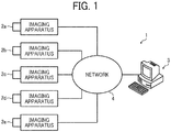
- FIG. 1 illustrates a process determining apparatus 1 according to an exemplary embodiment.
- the process determining apparatus 1 includes a plurality of imaging apparatuses 2a, 2b, 2c, 2d, and 2e as cameras, and a personal computer 3 as a determination unit (hereinafter referred to as a determination unit 3). Since each of the imaging apparatuses 2a, 2b, 2c, 2d, and 2e is similar to every other, the imaging apparatuses 2a, 2b, 2c, 2d, and 2e are collectively called imaging apparatuses 2 in the following description. Each of the imaging apparatuses 2 and the determination unit 3 are connected via a network 4.
- Each of the imaging apparatuses 2 is disposed with respect to each process performed by an operating unit 5 which will be described below.
- a plurality of imaging apparatuses 2 may be disposed with respect to one process.
- the determination unit 3 is connected to an external device such as a hard disk drive (HDD), so that image data captured by each of the imaging apparatuses 2 and each setting data are stored in the external device.
- the network 4 as an information transmission path includes a universal serial bus (USB) and a local area network (LAN) cable.
- FIG. 2 illustrates a control block diagram of the determination unit 3.
- the determination unit 3 includes a picture receiving unit 3a, an input unit 3b, a setting unit 3c, and a storage unit 3d.
- the picture receiving unit 3a acquires an image from each of the imaging apparatuses 2.
- the input unit 3b is used when an operation is input for each of various settings.
- the setting unit 3c sets various information, and the storage unit 3d stores image data and the various setting information.
- the determination unit 3 includes a playback unit 3e, a designation unit 3f, a registration unit 3g, and a difference calculator 3h.
- the playback unit 3e plays back an acquisition image or a picture of a video file, and the designation unit 3f designates a particular region within image data.
- the registration unit 3g is a member in which coordinates of the particular region and a reference image within the particular region are registered.
- the difference calculator 3h calculates a difference between two images.
- the determination unit 3 includes a determiner 3i, a data output unit 3j, a display controller 3k, and a display unit 31.
- the determiner 3i determines whether a process is normal or malfunctioning based on a difference between the reference image which has been stored and the acquisition image which has been acquired.
- the data output unit 3j outputs determination result data provided by the determiner 3i.
- the display controller 3k controls a display operation, and the display unit 31 displays various data.
- FIG. 3 is a schematic diagram illustrating a work process in which the imaging apparatus 2 of the process determining apparatus 1 is disposed according to the exemplary embodiment.
- the operating unit 5 as a robot includes an adsorption unit 5a, so that a workpiece 6 as a target object is adsorbed and retained at a tip of the adsorption unit 5a.
- the operating unit 5 is a folding robot
- the workpiece 6 is a paper box
- the process determining apparatus 1 determines whether the workpiece 6 is correctly arranged in a predetermined position.
- the imaging apparatus 2 successively capture images of operation and movement of the operating unit 5 and the workpiece 6.
- FIG. 4 is a flowchart illustrating an operation performed when the process determining apparatus 1 stores a reference image. That is, FIG. 4 is a flowchart illustrating a normal image registration operation.
- the normal image registration operation of the process determining apparatus 1 is described.
- an operation instruction is transmitted to the process determining apparatus 1, and a signal for the normal image registration operation is input.
- the imaging apparatus 2 is fixed to capture images of a series of operations of the operating unit 5 in operation.
- the determination unit 3 reads the image data captured by the imaging apparatus 2 from the storage unit 3d after the images are captured by the imaging apparatus 2.
- step ST02 the determination unit 3 sets an image region that is used for a difference process for finding a determination time of a reference image as a trigger region.
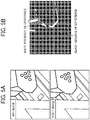
- the determination unit 3 extracts two images at predetermined times from successive image data as illustrated in FIG. 5A to determine whether each image, that is, the workpiece 6, has stopped.
- each of the images is generated as a binarized image as illustrated in FIG. 5B , and a position of the binarized image is determined.
- images are successively extracted as illustrated in FIG. 6 .
- the workpiece 6 as a monitoring target is monitored until the workpiece 6 stops, and a position in which the workpiece 6 has stopped is set as the trigger region.
- the two binarized images when the two binarized images become completely black, it is determined that the workpiece 6 has stopped. However, the two binarized images barely become complete black. Thus, if black has a threshold value or higher (e.g., if an area ratio of the black is a predetermined value ⁇ or higher), it is determined that the workpiece 6 has stopped.
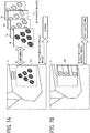
- the determination unit 3 sets an image region that is used for a difference process for determining whether the workpiece 6 in the stop location is normal as a determination region.
- the determination region is set by extracting a distinctive portion that is a particular image of the workpiece 6. For example, a logo mark is extracted to set the determination region.
- the determination unit 3 sets a portion of the workpiece 6 corresponding to the logo mark as a determination region 6a, and snips the determination region 6a as a reference image to register the determination region 6a as the reference image (hereinafter also referred to as the reference image 6a) in the registration unit 3g.
- the determination unit 3 compares the set reference image with the acquisition image acquired in the process to be determined.
- the set reference image and the acquisition image do not need to completely match each other. If the set reference image matches the acquisition image with a certain matching rate (e.g., if an area matching ratio is a predetermined value ⁇ or higher), the determination unit 3 determines that the set reference image and the acquisition image match each other.
- a certain matching rate e.g., if an area matching ratio is a predetermined value ⁇ or higher
- the determination unit 3 sets a parameter after the reference image 6a is registered.
- the parameter is a threshold value of each difference calculation value, and includes the threshold value ⁇ of the trigger region setting described above in step ST02 and the threshold value ⁇ of the matching ratio described above in step ST04.
- the threshold values ⁇ and ⁇ are respectively set to 98% and 95%.
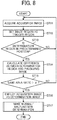
- step ST11 when a process determining operation instruction is input to the process determining apparatus 1, the determination unit 3 reads image data captured by the imaging apparatus 2 from the storage unit 3d to acquire an image for process determination. That is, the determination unit 3 acquires an acquisition image.
- step ST12 the determination unit 3 sets an image region that is used for a difference process for finding a determination time of the acquisition image as a trigger region.
- step ST13 the determination unit 3 determines whether the determination region is roughly in a predetermined position.
- step ST14 the determination unit 3 binarizes a determination region acquired as similar to the above acquisition and a preceding image to calculate a difference between the determination region and the preceding image.
- step ST15 the determination unit 3 determines whether a same area ratio exceeds a threshold value ⁇ . If the same area ratio is the threshold value ⁇ or lower (NO in step ST15), the process returns to step ST11 in which an acquisition image is acquired again.
- step ST15 if the same area ratio exceeds the threshold value ⁇ (YES in step ST15), the process proceeds to step ST16 in which the determination unit 3 employs such an acquisition image as a determination image.
- step ST17 the determination unit 3 determines whether the process is normal.
- step ST21 when the determination operation is started, the determination unit 3 reads registered reference images (images 6b, 6c, 6d, and 6e illustrated in FIG. 7A ) from the registration unit 3g.
- step ST22 the determination unit 3 compares each of the reference images 6b, 6c, 6d, and 6e with the acquisition image acquired in step ST11 of the flowchart illustrated FIG. 8 to calculate a difference. If the calculated difference is less than a threshold value ⁇ (YES in step ST22), that is, an area matching ratio exceeds the threshold value ⁇ , the process proceeds to step ST23.
- a threshold value ⁇ YES in step ST22
- step ST23 the determination unit 3 determines that the process is normal, and displays a message indicating the normal process on the display unit 31. Then, the determination operation ends.
- the process proceeds to step ST24.
- step ST24 the determination unit 3 determines that the process is malfunctioning, and displays a message indicating the malfunctioning process on the display unit 31. Then, the determination operation ends.
- FIG. 10 is a schematic diagram illustrating one example of an output result of the process determining operation performed by the process determining apparatus 1.
- the example illustrated in FIG. 10 includes an imaging apparatus number, a process determination result, and a normal image number. However, the output result is not limited thereto. Moreover, the result may be displayed on the display unit 31 or printed out.
- the process determining operation is performed.
- a stop location in which the workpiece 6 has stopped is extracted based on operation images.
- a particular image of the workpiece 6 in the stop location is extracted, and the extracted image is stored as the reference image 6a.
- the determination unit 3 compares the stored reference image 6a with an acquisition image acquired in a process to be determined to determine whether the process to be determined is normally performed.
- Such a configuration enables setting of a trigger region as a determination trigger and determination of whether the process is normal to be performed using only images captured by the imaging apparatus 2.
- the imaging apparatus 2 and the operating unit 5 do not need to exchange the determination trigger. Therefore, such a configuration can reliably prevent a failure caused by influence of an image acquisition delay or influence of a wiring state of a signal wire, and enables a normal/malfunction determination to be more reliably and easily performed.
- the trigger region is acquired in the stop location in which the workpiece 6 has completely stopped.
- Such acquisition can prevent a failure caused by a shift in angle or a shift in time when an image is captured by the imaging apparatus 2, and thus process determination can be performed with accuracy.
- the process determining apparatus 1 performs the process determining method, so that the imaging apparatus 2 and the operating unit 5 do not need to exchange a determination trigger. Hence, a failure caused by influence of an image acquisition delay or influence of a wiring state of a signal wire can be reliably prevented, and normal/malfunction determination can be more reliably and easily performed.
Landscapes
- Engineering & Computer Science (AREA)
- Physics & Mathematics (AREA)
- General Physics & Mathematics (AREA)
- Theoretical Computer Science (AREA)
- Multimedia (AREA)
- Quality & Reliability (AREA)
- Computer Vision & Pattern Recognition (AREA)
- Image Analysis (AREA)
- General Factory Administration (AREA)
Abstract
Description
- Exemplary aspects of the present disclosure relate to a process determining apparatus and a process determining method.
- In recent years, the manufacturing industry has expanded its emphasis in automation of production process by using machinery such as a robot. Meanwhile, a malfunction in the automated process in a place where no worker is involved must be promptly identified to increase a facility operating rate. Accordingly, there is a technique for determining whether the process is normal or malfunctioning based on image comparison and difference calculation. In particular, a position or orientation of a production facility or workpiece is observed using images captured by a camera. Such images are compared with an image in a normal state, and a difference is calculated. Since the technique has difficulty in determining a time when the image in the normal state or the image for the determination should be snipped as a static image from pictures captured by the camera, a determination unit and a receiving unit are used. The determination unit makes a determination at a certain time interval, whereas the receiving unit receives a timing signal indicating that a workpiece has stopped at a predetermined position from a production facility.
- In multi-item small production, multiple items are often produced in one production facility, and a tact time of such a production facility is not always constant. Thus, the determination unit needs to perform a cumbersome task of setting a tact time for each item. Moreover, even if a time when the camera captures an image is slightly shifted due to a delay, there is a possibility the receiving unit may observe blurred images captured before and after the workpiece stops. In such a case, a normal determination cannot be made. Accordingly, a technique (e.g.,
JP-4349298-B1 JP-2006-228029-A - The technique disclosed in
JP-4349298-B1 JP-2006-228029-A JP-4349298-B1 JP-2006-228029-A - In at least one embodiment of this disclosure, there is provided an improved process determining apparatus that includes an imaging apparatus and a determination unit. The imaging apparatus captures a plurality of operation images of an operating unit that performs a plurality of processes on a target object according to an operation sequence. The determination unit determines whether the plurality of processes is normally performed based on the plurality of operation images of the operating unit captured by the imaging apparatus. The determination unit extracts a stop location in which the target object has stopped in one of the plurality of processes from the plurality of operation images, stores a particular image of the target object in the extracted stop location as a reference image, and compares the stored reference image with an acquisition image acquired in the one of the plurality of processes to determine whether the one of the plurality of processes is normally performed.
- In at least one embodiment of this disclosure, there is provided an improved process determining method that includes capturing and determining. The capturing captures a plurality of images of operations of an operating unit that performs a plurality of processes on a target object according to an operation sequence. The determining determines whether the plurality of processes is normally performed based on the plurality of captured operation images of the operating unit. The determining includes a first process in which a stop location in which the target object has stopped in one of the plurality of processes is extracted from the plurality of operation images, a second process in which a particular image of the target object in the extracted stop location is stored as a reference image, and a third process in which the reference image and an acquisition image acquired in the one of the plurality of processes are compared to determine whether the one of the plurality of processes is normally performed.
- According to the present disclosure, since setting of a trigger region as a determination trigger and determination of whether a process is normal are performed using only images captured by the imaging apparatus, the imaging apparatus and the operating unit do not need to exchange the determination trigger. Thus, such a configuration can reliably prevent a failure caused by influence of an image acquisition delay or influence of a wiring state of a signal wire, and enables normal/malfunction determination to be more reliably and easily performed.
- The aforementioned and other aspects, features, and advantages of the present disclosure would be better understood by reference to the following detailed description when considered in connection with the accompanying drawings, wherein:
-
FIG. 1 is a schematic diagram illustrating a process determining apparatus according to an exemplary embodiment; -
FIG. 2 is a control block diagram of a determination unit according to the exemplary embodiment; -
FIG. 3 is a schematic diagram illustrating a work process in which an imaging apparatus is disposed according to the exemplary embodiment; -
FIG. 4 is a flowchart illustrating a normal image registration operation according to the exemplary embodiment; -
FIGs. 5A and 5B are schematic diagrams illustrating a trigger region setting according to the exemplary embodiment; -
FIG. 6 is a schematic diagram illustrating the trigger region setting according to the exemplary embodiment; -
FIGs. 7A and 7B are schematic diagrams illustrating a determination region setting according to the exemplary embodiment; -
FIG. 8 is a flowchart illustrating a process determining operation according to the exemplary embodiment; -
FIG. 9 is a flowchart illustrating a normal/malfunction determination according to the exemplary embodiment; and -
FIG. 10 is a schematic diagram illustrating one example of a process determination result according to the exemplary embodiment. - The accompanying drawings are intended to depict exemplary embodiments of the present disclosure and should not be interpreted to limit the scope thereof. The accompanying drawings are not to be considered as drawn to scale unless explicitly noted.
- In describing embodiments illustrated in the drawings, specific terminology is employed for the sake of clarity. However, the disclosure of this patent specification is not intended to be limited to the specific terminology so selected and it is to be understood that each specific element includes all technical equivalents that have the same function, operate in a similar manner and achieve similar results.
- Although the exemplary embodiments are described with technical limitations with reference to the attached drawings, such description is not intended to limit the scope of the disclosure and all of the components or elements described in the exemplary embodiments of this disclosure are not necessarily indispensable.
- Referring now to the drawings, exemplary embodiments of the present disclosure are described below. In the drawings for explaining the following exemplary embodiments, the same reference codes are allocated to elements (members or components) having the same function or shape and redundant descriptions thereof are omitted below.
-
FIG. 1 illustrates aprocess determining apparatus 1 according to an exemplary embodiment. InFIG. 1 , theprocess determining apparatus 1 includes a plurality ofimaging apparatuses personal computer 3 as a determination unit (hereinafter referred to as a determination unit 3). Since each of theimaging apparatuses imaging apparatuses imaging apparatuses 2 in the following description. Each of theimaging apparatuses 2 and thedetermination unit 3 are connected via anetwork 4. Each of theimaging apparatuses 2 is disposed with respect to each process performed by anoperating unit 5 which will be described below. A plurality ofimaging apparatuses 2 may be disposed with respect to one process. Thedetermination unit 3 is connected to an external device such as a hard disk drive (HDD), so that image data captured by each of theimaging apparatuses 2 and each setting data are stored in the external device. Thenetwork 4 as an information transmission path includes a universal serial bus (USB) and a local area network (LAN) cable. -
FIG. 2 illustrates a control block diagram of thedetermination unit 3. As illustrated inFIG. 2 , thedetermination unit 3 includes apicture receiving unit 3a, aninput unit 3b, asetting unit 3c, and astorage unit 3d. Thepicture receiving unit 3a acquires an image from each of theimaging apparatuses 2. Theinput unit 3b is used when an operation is input for each of various settings. Thesetting unit 3c sets various information, and thestorage unit 3d stores image data and the various setting information. Moreover, thedetermination unit 3 includes aplayback unit 3e, adesignation unit 3f, aregistration unit 3g, and adifference calculator 3h. Theplayback unit 3e plays back an acquisition image or a picture of a video file, and thedesignation unit 3f designates a particular region within image data. Theregistration unit 3g is a member in which coordinates of the particular region and a reference image within the particular region are registered. Thedifference calculator 3h calculates a difference between two images. Moreover, thedetermination unit 3 includes adeterminer 3i, adata output unit 3j, adisplay controller 3k, and adisplay unit 31. Thedeterminer 3i determines whether a process is normal or malfunctioning based on a difference between the reference image which has been stored and the acquisition image which has been acquired. Thedata output unit 3j outputs determination result data provided by thedeterminer 3i. Thedisplay controller 3k controls a display operation, and thedisplay unit 31 displays various data. -
FIG. 3 is a schematic diagram illustrating a work process in which theimaging apparatus 2 of theprocess determining apparatus 1 is disposed according to the exemplary embodiment. InFIG. 3 , theoperating unit 5 as a robot includes anadsorption unit 5a, so that aworkpiece 6 as a target object is adsorbed and retained at a tip of theadsorption unit 5a. In the exemplary embodiment, for example, theoperating unit 5 is a folding robot, theworkpiece 6 is a paper box, and theprocess determining apparatus 1 determines whether theworkpiece 6 is correctly arranged in a predetermined position. Theimaging apparatus 2 successively capture images of operation and movement of theoperating unit 5 and theworkpiece 6. -
FIG. 4 is a flowchart illustrating an operation performed when theprocess determining apparatus 1 stores a reference image. That is,FIG. 4 is a flowchart illustrating a normal image registration operation. Hereinafter, the normal image registration operation of theprocess determining apparatus 1 is described. First, an operation instruction is transmitted to theprocess determining apparatus 1, and a signal for the normal image registration operation is input. When such a signal is input, theimaging apparatus 2 is fixed to capture images of a series of operations of theoperating unit 5 in operation. In step ST01, thedetermination unit 3 reads the image data captured by theimaging apparatus 2 from thestorage unit 3d after the images are captured by theimaging apparatus 2. Subsequently, in step ST02, thedetermination unit 3 sets an image region that is used for a difference process for finding a determination time of a reference image as a trigger region. - When the trigger region is set, the
determination unit 3 extracts two images at predetermined times from successive image data as illustrated inFIG. 5A to determine whether each image, that is, theworkpiece 6, has stopped. In the exemplary embodiment, each of the images is generated as a binarized image as illustrated inFIG. 5B , and a position of the binarized image is determined. When each of the images has a difference as illustrated inFIG. 5B , that is, it is determined that there is movement, images are successively extracted as illustrated inFIG. 6 . Theworkpiece 6 as a monitoring target is monitored until theworkpiece 6 stops, and a position in which theworkpiece 6 has stopped is set as the trigger region. In the exemplary embodiment, when the two binarized images become completely black, it is determined that theworkpiece 6 has stopped. However, the two binarized images barely become complete black. Thus, if black has a threshold value or higher (e.g., if an area ratio of the black is a predetermined value α or higher), it is determined that theworkpiece 6 has stopped. - Subsequently, in step ST03, the
determination unit 3 sets an image region that is used for a difference process for determining whether theworkpiece 6 in the stop location is normal as a determination region. As illustrated inFIG. 7A , the determination region is set by extracting a distinctive portion that is a particular image of theworkpiece 6. For example, a logo mark is extracted to set the determination region. In step ST04, thedetermination unit 3 sets a portion of theworkpiece 6 corresponding to the logo mark as adetermination region 6a, and snips thedetermination region 6a as a reference image to register thedetermination region 6a as the reference image (hereinafter also referred to as thereference image 6a) in theregistration unit 3g. In the exemplary embodiment, thedetermination unit 3 compares the set reference image with the acquisition image acquired in the process to be determined. The set reference image and the acquisition image do not need to completely match each other. If the set reference image matches the acquisition image with a certain matching rate (e.g., if an area matching ratio is a predetermined value β or higher), thedetermination unit 3 determines that the set reference image and the acquisition image match each other. - In step ST05, the
determination unit 3 sets a parameter after thereference image 6a is registered. Herein, the parameter is a threshold value of each difference calculation value, and includes the threshold value α of the trigger region setting described above in step ST02 and the threshold value β of the matching ratio described above in step ST04. In the exemplary embodiment, for example, the threshold values α and β are respectively set to 98% and 95%. When a series of such setting processes is finished, the normal image registration operation ends. - Next, a process determining operation performed by the
process determining apparatus 1 is described with reference a flowchart illustrated inFIG. 8 . The process determining operation is performed after the normal image registration operation described inFIG. 4 ends. In step ST11, when a process determining operation instruction is input to theprocess determining apparatus 1, thedetermination unit 3 reads image data captured by theimaging apparatus 2 from thestorage unit 3d to acquire an image for process determination. That is, thedetermination unit 3 acquires an acquisition image. - Subsequently, in step ST12, the
determination unit 3 sets an image region that is used for a difference process for finding a determination time of the acquisition image as a trigger region. In step ST13, thedetermination unit 3 determines whether the determination region is roughly in a predetermined position. In step ST14, thedetermination unit 3 binarizes a determination region acquired as similar to the above acquisition and a preceding image to calculate a difference between the determination region and the preceding image. In step ST15, thedetermination unit 3 determines whether a same area ratio exceeds a threshold value α. If the same area ratio is the threshold value α or lower (NO in step ST15), the process returns to step ST11 in which an acquisition image is acquired again. On the other hand, if the same area ratio exceeds the threshold value α (YES in step ST15), the process proceeds to step ST16 in which thedetermination unit 3 employs such an acquisition image as a determination image. In step ST17, thedetermination unit 3 determines whether the process is normal. - An operation of the normal/malfunction determination in step ST17 of the flowchart illustrated in
FIG. 8 is described with reference to the flowchart illustrated inFIG. 9 . In step ST21, when the determination operation is started, thedetermination unit 3 reads registered reference images (images FIG. 7A ) from theregistration unit 3g. In step ST22, thedetermination unit 3 compares each of thereference images FIG. 8 to calculate a difference. If the calculated difference is less than a threshold value β (YES in step ST22), that is, an area matching ratio exceeds the threshold value β, the process proceeds to step ST23. In step ST23, thedetermination unit 3 determines that the process is normal, and displays a message indicating the normal process on thedisplay unit 31. Then, the determination operation ends. On the other hand, if the calculated difference exceeds the threshold value β (NO in step ST22), that is, the area matching ratio is less than the threshold value β, the process proceeds to step ST24. In step ST24, thedetermination unit 3 determines that the process is malfunctioning, and displays a message indicating the malfunctioning process on thedisplay unit 31. Then, the determination operation ends.FIG. 10 is a schematic diagram illustrating one example of an output result of the process determining operation performed by theprocess determining apparatus 1. The example illustrated inFIG. 10 includes an imaging apparatus number, a process determination result, and a normal image number. However, the output result is not limited thereto. Moreover, the result may be displayed on thedisplay unit 31 or printed out. - According to the exemplary embodiment, the process determining operation is performed. In such an operation, a stop location in which the
workpiece 6 has stopped is extracted based on operation images. Subsequently, a particular image of theworkpiece 6 in the stop location is extracted, and the extracted image is stored as thereference image 6a. Accordingly, thedetermination unit 3 compares the storedreference image 6a with an acquisition image acquired in a process to be determined to determine whether the process to be determined is normally performed. Such a configuration enables setting of a trigger region as a determination trigger and determination of whether the process is normal to be performed using only images captured by theimaging apparatus 2. Thus, theimaging apparatus 2 and theoperating unit 5 do not need to exchange the determination trigger. Therefore, such a configuration can reliably prevent a failure caused by influence of an image acquisition delay or influence of a wiring state of a signal wire, and enables a normal/malfunction determination to be more reliably and easily performed. - Moreover, the trigger region is acquired in the stop location in which the
workpiece 6 has completely stopped. Such acquisition can prevent a failure caused by a shift in angle or a shift in time when an image is captured by theimaging apparatus 2, and thus process determination can be performed with accuracy. Moreover, theprocess determining apparatus 1 performs the process determining method, so that theimaging apparatus 2 and theoperating unit 5 do not need to exchange a determination trigger. Hence, a failure caused by influence of an image acquisition delay or influence of a wiring state of a signal wire can be reliably prevented, and normal/malfunction determination can be more reliably and easily performed. - The present disclosure has been described above with reference to specific exemplary embodiments but is not limited thereto. Various modifications and enhancements are possible without departing from scope of the disclosure. It is therefore to be understood that the present disclosure may be practiced otherwise than as specifically described herein. For example, elements and/or features of different illustrative exemplary embodiments may be combined with each other and/or substituted for each other within the scope of the present disclosure.
Claims (5)
- A process determining apparatus (1) comprising:an imaging apparatus (2) to capture a plurality of operation images of an operating unit (5) that performs a plurality of processes on a target object (6) according to an operation sequence; anda determination unit (3) to determine whether the plurality of processes is normally performed based on the plurality of operation images of the operating unit captured by the imaging apparatus,wherein the determination unit extracts a stop location in which the target object has stopped in one of the plurality of processes from the plurality of operation images, stores a particular image of the target object in the extracted stop location as a reference image, and compares the stored reference image with an acquisition image acquired in the one of the plurality of processes to determine whether the one of the plurality of processes is normally performed.
- The process determining apparatus according to claim 1, wherein the determination unit determines the stop location based on a difference of the plurality of operation images.
- The process determining apparatus according to claim 2, wherein the determination unit binarizes the plurality of operation images to determine the difference.
- The process determining apparatus according to claim 3, wherein the difference is determined based on a predetermined threshold value.
- A process determining method comprising:capturing a plurality of images of operations of an operating unit that performs a plurality of processes on a target object according to an operation sequence; anddetermining whether the plurality of processes is normally performed based on the plurality of captured operation images of the operating unit,wherein the determining includes a first process in which a stop location in which the target object has stopped in one of the plurality of processes is extracted from the plurality of operation images, a second process in which a particular image of the target object in the extracted stop location is stored as a reference image, and a third process in which the reference image and an acquisition image acquired in the one of the plurality of processes are compared to determine whether the one of the plurality of processes is normally performed.
Applications Claiming Priority (1)
| Application Number | Priority Date | Filing Date | Title |
|---|---|---|---|
| JP2016137030A JP7111444B2 (en) | 2016-07-11 | 2016-07-11 | Judgment unit, process judgment device and process judgment method |
Publications (1)
| Publication Number | Publication Date |
|---|---|
| EP3270353A1 true EP3270353A1 (en) | 2018-01-17 |
Family
ID=59655829
Family Applications (1)
| Application Number | Title | Priority Date | Filing Date |
|---|---|---|---|
| EP17179367.2A Ceased EP3270353A1 (en) | 2016-07-11 | 2017-07-03 | Process determining apparatus and process determining method |
Country Status (3)
| Country | Link |
|---|---|
| EP (1) | EP3270353A1 (en) |
| JP (1) | JP7111444B2 (en) |
| CN (1) | CN107610089A (en) |
Cited By (1)
| Publication number | Priority date | Publication date | Assignee | Title |
|---|---|---|---|---|
| CN112640055A (en) * | 2018-08-21 | 2021-04-09 | 株式会社斯库林集团 | Substrate processing method, substrate processing apparatus, and substrate processing system |
Families Citing this family (4)
| Publication number | Priority date | Publication date | Assignee | Title |
|---|---|---|---|---|
| JP7171407B2 (en) * | 2018-12-12 | 2022-11-15 | 株式会社日立製作所 | Information processing device, production instruction support method |
| JP2021152889A (en) | 2020-03-23 | 2021-09-30 | 株式会社リコー | Image processing system and image processing method |
| KR102477085B1 (en) * | 2022-04-07 | 2022-12-14 | 세이지리서치 주식회사 | A method for detecting a process motion and a device for detecting a process motion |
| KR102478499B1 (en) * | 2022-04-07 | 2022-12-20 | 세이지리서치 주식회사 | A method for controlling a prosess and a device for controlling a process |
Citations (2)
| Publication number | Priority date | Publication date | Assignee | Title |
|---|---|---|---|---|
| US20050240376A1 (en) * | 2004-04-21 | 2005-10-27 | Fuji Xerox Co., Ltd. | Failure diagnosis method, failure diagnosis apparatus, image forming apparatus, program, and storage medium |
| JP2006228029A (en) | 2005-02-18 | 2006-08-31 | Denso Corp | Monitoring control apparatus and monitoring control method |
Family Cites Families (10)
| Publication number | Priority date | Publication date | Assignee | Title |
|---|---|---|---|---|
| JP2006260443A (en) * | 2005-03-18 | 2006-09-28 | Denso Corp | Monitoring control apparatus and monitoring control method |
| CN100508555C (en) * | 2007-03-23 | 2009-07-01 | 北京中星微电子有限公司 | Static object detecting method and system |
| JP4654347B2 (en) * | 2007-12-06 | 2011-03-16 | 株式会社融合技術研究所 | Abnormal operation monitoring device |
| JP5186973B2 (en) * | 2008-03-26 | 2013-04-24 | 株式会社明電舎 | Worker safety inspection device |
| JP5816511B2 (en) * | 2011-10-04 | 2015-11-18 | オリンパス株式会社 | Image processing apparatus, endoscope apparatus, and operation method of image processing apparatus |
| JP2014071482A (en) * | 2012-09-27 | 2014-04-21 | Panasonic Corp | Object detection device |
| JP2014220772A (en) * | 2013-05-10 | 2014-11-20 | キヤノン株式会社 | Image processing apparatus and control method and program of the same |
| CN103745485A (en) * | 2013-12-31 | 2014-04-23 | 深圳泰山在线科技有限公司 | Method and system for judging object stillness or movement |
| JP6554825B2 (en) * | 2014-08-25 | 2019-08-07 | 株式会社リコー | Image processing apparatus, image processing system, image processing method, and program |
| CN104966045B (en) * | 2015-04-02 | 2018-06-05 | 北京天睿空间科技有限公司 | Aircraft disengaging berth automatic testing method based on video |
-
2016
- 2016-07-11 JP JP2016137030A patent/JP7111444B2/en not_active Expired - Fee Related
-
2017
- 2017-07-03 EP EP17179367.2A patent/EP3270353A1/en not_active Ceased
- 2017-07-10 CN CN201710555395.5A patent/CN107610089A/en active Pending
Patent Citations (3)
| Publication number | Priority date | Publication date | Assignee | Title |
|---|---|---|---|---|
| US20050240376A1 (en) * | 2004-04-21 | 2005-10-27 | Fuji Xerox Co., Ltd. | Failure diagnosis method, failure diagnosis apparatus, image forming apparatus, program, and storage medium |
| JP2006228029A (en) | 2005-02-18 | 2006-08-31 | Denso Corp | Monitoring control apparatus and monitoring control method |
| JP4349298B2 (en) | 2005-02-18 | 2009-10-21 | 株式会社デンソー | Monitoring control apparatus and monitoring control method |
Non-Patent Citations (1)
| Title |
|---|
| HENRI FENNANDER ET AL: "Visual measurement and tracking in laser hybrid welding", MACHINE VISION AND APPLICATIONS, SPRINGER, BERLIN, DE, vol. 20, no. 2, 20 November 2007 (2007-11-20), pages 103 - 118, XP019699734, ISSN: 1432-1769 * |
Cited By (1)
| Publication number | Priority date | Publication date | Assignee | Title |
|---|---|---|---|---|
| CN112640055A (en) * | 2018-08-21 | 2021-04-09 | 株式会社斯库林集团 | Substrate processing method, substrate processing apparatus, and substrate processing system |
Also Published As
| Publication number | Publication date |
|---|---|
| JP2018010368A (en) | 2018-01-18 |
| CN107610089A (en) | 2018-01-19 |
| JP7111444B2 (en) | 2022-08-02 |
Similar Documents
| Publication | Publication Date | Title |
|---|---|---|
| JP2012254518A (en) | Robot control system, robot system and program | |
| TW202134808A (en) | Systems, methods, and media for manufacturing processes | |
| JP7111444B2 (en) | Judgment unit, process judgment device and process judgment method | |
| JP6331517B2 (en) | Image processing apparatus, system, image processing method, and image processing program | |
| EP2903005A1 (en) | Video event recording system | |
| JP6805199B2 (en) | Equipment monitoring system | |
| US9864908B2 (en) | Slow change detection system | |
| WO2021131552A1 (en) | Operation analyzing device and operation analyzing method | |
| JP2016179527A (en) | Robot controller having function of diagnosing abnormality of robot | |
| EP4070922A3 (en) | Robot system, control method, image processing apparatus, image processing method, method of manufacturing products, program, and recording medium | |
| JP6922239B2 (en) | Process monitoring device, control method and program of process monitoring device | |
| US20200193354A1 (en) | Information processing device and production instruction support method | |
| EP3444080A1 (en) | Actuator control system, actuator control method, information-processing program, and recording medium | |
| CN106922194B (en) | Abnormality detection device and abnormality detection method | |
| US10007837B2 (en) | Determining the robot axis angle and selection of a robot with the aid of a camera | |
| JP2022155615A (en) | Monitoring method, monitoring system, and program | |
| US11321656B2 (en) | Difference extracting device | |
| EP3495906B1 (en) | Method of process monitoring in a machine | |
| JP6337530B2 (en) | Image processing apparatus, image processing method, and image processing program | |
| EP3351927B1 (en) | Inspection system, controller, inspection method, and inspection program | |
| WO2017183107A1 (en) | Unsteadiness detection device, unsteadiness detection system, and unsteadiness detection method | |
| JP2012236266A (en) | Robot control system, robot system, and program | |
| JP2015136763A (en) | Control device, robot system, robot, and robot control method | |
| US20220122290A1 (en) | Visual Line Analysis Apparatus, Visual Line Analysis Method, and Visual Line Analysis System | |
| JP2017146662A (en) | Mobile monitoring system |
Legal Events
| Date | Code | Title | Description |
|---|---|---|---|
| PUAI | Public reference made under article 153(3) epc to a published international application that has entered the european phase |
Free format text: ORIGINAL CODE: 0009012 |
|
| STAA | Information on the status of an ep patent application or granted ep patent |
Free format text: STATUS: REQUEST FOR EXAMINATION WAS MADE |
|
| 17P | Request for examination filed |
Effective date: 20170703 |
|
| AK | Designated contracting states |
Kind code of ref document: A1 Designated state(s): AL AT BE BG CH CY CZ DE DK EE ES FI FR GB GR HR HU IE IS IT LI LT LU LV MC MK MT NL NO PL PT RO RS SE SI SK SM TR |
|
| AX | Request for extension of the european patent |
Extension state: BA ME |
|
| STAA | Information on the status of an ep patent application or granted ep patent |
Free format text: STATUS: EXAMINATION IS IN PROGRESS |
|
| 17Q | First examination report despatched |
Effective date: 20190430 |
|
| STAA | Information on the status of an ep patent application or granted ep patent |
Free format text: STATUS: THE APPLICATION HAS BEEN REFUSED |
|
| 18R | Application refused |
Effective date: 20210305 |