EP3270264A1 - Electronic device with gesture actuation of companion devices and corresponding systems and methods - Google Patents
Electronic device with gesture actuation of companion devices and corresponding systems and methods Download PDFInfo
- Publication number
- EP3270264A1 EP3270264A1 EP17179859.8A EP17179859A EP3270264A1 EP 3270264 A1 EP3270264 A1 EP 3270264A1 EP 17179859 A EP17179859 A EP 17179859A EP 3270264 A1 EP3270264 A1 EP 3270264A1
- Authority
- EP
- European Patent Office
- Prior art keywords
- electronic device
- companion
- user
- gesture
- wireless communication
- Prior art date
- Legal status (The legal status is an assumption and is not a legal conclusion. Google has not performed a legal analysis and makes no representation as to the accuracy of the status listed.)
- Withdrawn
Links
Images





Classifications
-
- G—PHYSICS
- G06—COMPUTING OR CALCULATING; COUNTING
- G06F—ELECTRIC DIGITAL DATA PROCESSING
- G06F21/00—Security arrangements for protecting computers, components thereof, programs or data against unauthorised activity
- G06F21/30—Authentication, i.e. establishing the identity or authorisation of security principals
- G06F21/31—User authentication
- G06F21/32—User authentication using biometric data, e.g. fingerprints, iris scans or voiceprints
-
- G—PHYSICS
- G06—COMPUTING OR CALCULATING; COUNTING
- G06F—ELECTRIC DIGITAL DATA PROCESSING
- G06F1/00—Details not covered by groups G06F3/00 - G06F13/00 and G06F21/00
- G06F1/26—Power supply means, e.g. regulation thereof
- G06F1/32—Means for saving power
- G06F1/3203—Power management, i.e. event-based initiation of a power-saving mode
- G06F1/3234—Power saving characterised by the action undertaken
- G06F1/3293—Power saving characterised by the action undertaken by switching to a less power-consuming processor, e.g. sub-CPU
-
- G—PHYSICS
- G06—COMPUTING OR CALCULATING; COUNTING
- G06F—ELECTRIC DIGITAL DATA PROCESSING
- G06F21/00—Security arrangements for protecting computers, components thereof, programs or data against unauthorised activity
- G06F21/30—Authentication, i.e. establishing the identity or authorisation of security principals
- G06F21/31—User authentication
- G06F21/36—User authentication by graphic or iconic representation
-
- G—PHYSICS
- G06—COMPUTING OR CALCULATING; COUNTING
- G06F—ELECTRIC DIGITAL DATA PROCESSING
- G06F3/00—Input arrangements for transferring data to be processed into a form capable of being handled by the computer; Output arrangements for transferring data from processing unit to output unit, e.g. interface arrangements
- G06F3/01—Input arrangements or combined input and output arrangements for interaction between user and computer
- G06F3/017—Gesture based interaction, e.g. based on a set of recognized hand gestures
-
- G—PHYSICS
- G06—COMPUTING OR CALCULATING; COUNTING
- G06F—ELECTRIC DIGITAL DATA PROCESSING
- G06F3/00—Input arrangements for transferring data to be processed into a form capable of being handled by the computer; Output arrangements for transferring data from processing unit to output unit, e.g. interface arrangements
- G06F3/01—Input arrangements or combined input and output arrangements for interaction between user and computer
- G06F3/03—Arrangements for converting the position or the displacement of a member into a coded form
- G06F3/033—Pointing devices displaced or positioned by the user, e.g. mice, trackballs, pens or joysticks; Accessories therefor
- G06F3/0346—Pointing devices displaced or positioned by the user, e.g. mice, trackballs, pens or joysticks; Accessories therefor with detection of the device orientation or free movement in a three-dimensional [3D] space, e.g. 3D mice, 6-DOF [six degrees of freedom] pointers using gyroscopes, accelerometers or tilt-sensors
-
- G—PHYSICS
- G06—COMPUTING OR CALCULATING; COUNTING
- G06F—ELECTRIC DIGITAL DATA PROCESSING
- G06F3/00—Input arrangements for transferring data to be processed into a form capable of being handled by the computer; Output arrangements for transferring data from processing unit to output unit, e.g. interface arrangements
- G06F3/01—Input arrangements or combined input and output arrangements for interaction between user and computer
- G06F3/048—Interaction techniques based on graphical user interfaces [GUI]
- G06F3/0487—Interaction techniques based on graphical user interfaces [GUI] using specific features provided by the input device, e.g. functions controlled by the rotation of a mouse with dual sensing arrangements, or of the nature of the input device, e.g. tap gestures based on pressure sensed by a digitiser
- G06F3/0488—Interaction techniques based on graphical user interfaces [GUI] using specific features provided by the input device, e.g. functions controlled by the rotation of a mouse with dual sensing arrangements, or of the nature of the input device, e.g. tap gestures based on pressure sensed by a digitiser using a touch-screen or digitiser, e.g. input of commands through traced gestures
- G06F3/04883—Interaction techniques based on graphical user interfaces [GUI] using specific features provided by the input device, e.g. functions controlled by the rotation of a mouse with dual sensing arrangements, or of the nature of the input device, e.g. tap gestures based on pressure sensed by a digitiser using a touch-screen or digitiser, e.g. input of commands through traced gestures for inputting data by handwriting, e.g. gesture or text
-
- G—PHYSICS
- G08—SIGNALLING
- G08C—TRANSMISSION SYSTEMS FOR MEASURED VALUES, CONTROL OR SIMILAR SIGNALS
- G08C17/00—Arrangements for transmitting signals characterised by the use of a wireless electrical link
- G08C17/02—Arrangements for transmitting signals characterised by the use of a wireless electrical link using a radio link
-
- H—ELECTRICITY
- H04—ELECTRIC COMMUNICATION TECHNIQUE
- H04M—TELEPHONIC COMMUNICATION
- H04M1/00—Substation equipment, e.g. for use by subscribers
- H04M1/72—Mobile telephones; Cordless telephones, i.e. devices for establishing wireless links to base stations without route selection
- H04M1/724—User interfaces specially adapted for cordless or mobile telephones
- H04M1/72403—User interfaces specially adapted for cordless or mobile telephones with means for local support of applications that increase the functionality
- H04M1/72409—User interfaces specially adapted for cordless or mobile telephones with means for local support of applications that increase the functionality by interfacing with external accessories
- H04M1/72412—User interfaces specially adapted for cordless or mobile telephones with means for local support of applications that increase the functionality by interfacing with external accessories using two-way short-range wireless interfaces
-
- H—ELECTRICITY
- H04—ELECTRIC COMMUNICATION TECHNIQUE
- H04M—TELEPHONIC COMMUNICATION
- H04M1/00—Substation equipment, e.g. for use by subscribers
- H04M1/72—Mobile telephones; Cordless telephones, i.e. devices for establishing wireless links to base stations without route selection
- H04M1/724—User interfaces specially adapted for cordless or mobile telephones
- H04M1/72403—User interfaces specially adapted for cordless or mobile telephones with means for local support of applications that increase the functionality
- H04M1/72409—User interfaces specially adapted for cordless or mobile telephones with means for local support of applications that increase the functionality by interfacing with external accessories
- H04M1/72415—User interfaces specially adapted for cordless or mobile telephones with means for local support of applications that increase the functionality by interfacing with external accessories for remote control of appliances
-
- H—ELECTRICITY
- H04—ELECTRIC COMMUNICATION TECHNIQUE
- H04W—WIRELESS COMMUNICATION NETWORKS
- H04W12/00—Security arrangements; Authentication; Protecting privacy or anonymity
- H04W12/50—Secure pairing of devices
-
- G—PHYSICS
- G06—COMPUTING OR CALCULATING; COUNTING
- G06F—ELECTRIC DIGITAL DATA PROCESSING
- G06F2203/00—Indexing scheme relating to G06F3/00 - G06F3/048
- G06F2203/038—Indexing scheme relating to G06F3/038
- G06F2203/0383—Remote input, i.e. interface arrangements in which the signals generated by a pointing device are transmitted to a PC at a remote location, e.g. to a PC in a LAN
-
- G—PHYSICS
- G06—COMPUTING OR CALCULATING; COUNTING
- G06F—ELECTRIC DIGITAL DATA PROCESSING
- G06F2203/00—Indexing scheme relating to G06F3/00 - G06F3/048
- G06F2203/038—Indexing scheme relating to G06F3/038
- G06F2203/0384—Wireless input, i.e. hardware and software details of wireless interface arrangements for pointing devices
-
- G—PHYSICS
- G08—SIGNALLING
- G08C—TRANSMISSION SYSTEMS FOR MEASURED VALUES, CONTROL OR SIMILAR SIGNALS
- G08C2201/00—Transmission systems of control signals via wireless link
- G08C2201/30—User interface
- G08C2201/32—Remote control based on movements, attitude of remote control device
-
- G—PHYSICS
- G08—SIGNALLING
- G08C—TRANSMISSION SYSTEMS FOR MEASURED VALUES, CONTROL OR SIMILAR SIGNALS
- G08C2201/00—Transmission systems of control signals via wireless link
- G08C2201/60—Security, fault tolerance
- G08C2201/61—Password, biometric
-
- G—PHYSICS
- G08—SIGNALLING
- G08C—TRANSMISSION SYSTEMS FOR MEASURED VALUES, CONTROL OR SIMILAR SIGNALS
- G08C2201/00—Transmission systems of control signals via wireless link
- G08C2201/90—Additional features
- G08C2201/91—Remote control based on location and proximity
-
- G—PHYSICS
- G08—SIGNALLING
- G08C—TRANSMISSION SYSTEMS FOR MEASURED VALUES, CONTROL OR SIMILAR SIGNALS
- G08C2201/00—Transmission systems of control signals via wireless link
- G08C2201/90—Additional features
- G08C2201/92—Universal remote control
-
- G—PHYSICS
- G08—SIGNALLING
- G08C—TRANSMISSION SYSTEMS FOR MEASURED VALUES, CONTROL OR SIMILAR SIGNALS
- G08C2201/00—Transmission systems of control signals via wireless link
- G08C2201/90—Additional features
- G08C2201/93—Remote control using other portable devices, e.g. mobile phone, PDA, laptop
-
- H—ELECTRICITY
- H04—ELECTRIC COMMUNICATION TECHNIQUE
- H04L—TRANSMISSION OF DIGITAL INFORMATION, e.g. TELEGRAPHIC COMMUNICATION
- H04L63/00—Network architectures or network communication protocols for network security
- H04L63/08—Network architectures or network communication protocols for network security for authentication of entities
- H04L63/0861—Network architectures or network communication protocols for network security for authentication of entities using biometrical features, e.g. fingerprint, retina-scan
-
- H—ELECTRICITY
- H04—ELECTRIC COMMUNICATION TECHNIQUE
- H04W—WIRELESS COMMUNICATION NETWORKS
- H04W12/00—Security arrangements; Authentication; Protecting privacy or anonymity
- H04W12/60—Context-dependent security
- H04W12/63—Location-dependent; Proximity-dependent
-
- H—ELECTRICITY
- H04—ELECTRIC COMMUNICATION TECHNIQUE
- H04W—WIRELESS COMMUNICATION NETWORKS
- H04W12/00—Security arrangements; Authentication; Protecting privacy or anonymity
- H04W12/60—Context-dependent security
- H04W12/68—Gesture-dependent or behaviour-dependent
-
- Y—GENERAL TAGGING OF NEW TECHNOLOGICAL DEVELOPMENTS; GENERAL TAGGING OF CROSS-SECTIONAL TECHNOLOGIES SPANNING OVER SEVERAL SECTIONS OF THE IPC; TECHNICAL SUBJECTS COVERED BY FORMER USPC CROSS-REFERENCE ART COLLECTIONS [XRACs] AND DIGESTS
- Y02—TECHNOLOGIES OR APPLICATIONS FOR MITIGATION OR ADAPTATION AGAINST CLIMATE CHANGE
- Y02D—CLIMATE CHANGE MITIGATION TECHNOLOGIES IN INFORMATION AND COMMUNICATION TECHNOLOGIES [ICT], I.E. INFORMATION AND COMMUNICATION TECHNOLOGIES AIMING AT THE REDUCTION OF THEIR OWN ENERGY USE
- Y02D10/00—Energy efficient computing, e.g. low power processors, power management or thermal management
Definitions
- This disclosure relates generally to electronic devices, and more particularly to portable electronic devices with motion sensors.
- Mobile electronic communication devices are used by billions of people. The owners of such devices use them for many different purposes including, but not limited to, voice communications, text messaging, Internet browsing, calendar management, commerce such as banking, and social networking.
- Embodiments of the disclosure do not recite the implementation of any commonplace business method aimed at processing business information, nor do they apply a known business process to the particular technological environment of the Internet. Moreover, embodiments of the disclosure do not create or alter contractual relations using generic computer functions and conventional network operations. Quite to the contrary, embodiments of the disclosure employ methods operable on hardware platforms that, when applied to electronic device and/or user interface technology, improve the functioning of the electronic device itself by simplifying companion device actuation to improve the overall user experience by overcoming problems specifically arising in the realm of the recently developed technology associated with electronic device user interaction.
- embodiments of the disclosure described herein may be comprised of one or more conventional processors and unique stored program instructions that control the one or more processors to implement, in conjunction with certain non-processor circuits, some, most, or all of the functions of controlling companion devices in response to biometric or gesture or motion input as described herein.
- the non-processor circuits may include, but are not limited to, a radio receiver, a radio transmitter, signal drivers, clock circuits, power source circuits, and other user input devices. As such, these functions may be interpreted as steps of a method to perform device control companion devices in response to one or more biometric, proximity, and/or motion sensors components.
- Embodiments of the disclosure provide secure and simple methods of unlocking, actuating, or otherwise controlling companion devices that are operable with an electronic device.
- companion devices include music players, televisions, media players, lights, thermostats, appliances, locks, and so forth.
- embodiments of the disclosure provide secure and simple methods of controlling a music player that is in wireless communication with an electronic device.
- a user can identify themself using a fingerprint sensor.
- a user can make a "key turn" simulation gesture to, for instance, turn on a music player operating within a wireless communication radius of the electronic device.
- this eliminates the need for a user to navigate to an application, and through the application, which may require several touches or user interactions with the display, to perform the same operation.
- an electronic device includes a biometric sensor, one example of which is a fingerprint sensor.
- the biometric sensor is responsible for identifying biometric input received at the biometric sensor.
- One or more processors, which are operable with the biometric sensor, then identify one or more companion devices operating within a wireless communication radius of the electronic device.
- the companion devices can include music players, wirelessly connected home devices and appliances, health trackers, tools, and so forth.
- one or more gesture sensors identify a predefined gesture input.
- the gesture sensors can include motion detectors, proximity detectors, or combinations thereof.
- One example of a predefined gesture input would be where the user holds the electronic device as if it were a key positioned within a lock, and then twists the electronic device about a major axis.
- a wireless communication circuit responsive to the one or more processors delivers an actuation credential to the one companion device.
- the actuation credential can actuate the companion device, control the companion device, deactuate the companion device, or perform other control operations.
- a user touches a fingerprint sensor and twists the electronic device with a key turn simulation as if it were a key in a lock to actuate a wireless music player to start enjoying smooth jazz during cocktail hour.
- embodiments of the disclosure provide a secure and fast way to lock, unlock, actuate, deactuate, or otherwise control a companion device.
- embodiments of the disclosure provide methods and systems for selecting between the various devices. Illustrating by example, in one embodiment a list of companion devices is presented on the display from which a user can select a single device prior to making the gesture. In another embodiment, an audible or other notification that there are multiple companion devices paired with the electronic device is delivered, from which a user may deliver an audible command such as "control the music player" prior to making the gesture.
- Other techniques for alerting the user to the fact that there are multiple companion devices operating within the predefined wireless radius will be obvious to those of ordinary skill in the art having the benefit of this disclosure.
- a combination of biometric authentication and gesture control is used to control a companion device.
- biometric authentication allows multiple users of a single device to control their specific companion devices.
- the one or more processors operating within the tablet computer can identify the family member though biometric identification, thereby allowing the user to control their specific devices without controlling another family member's companion devices.
- the biometric authentication also advantageously allows multiple users of a single electronic device to control differing access levels on a companion device. For instance, parents may not want their children to listen to heavy metal music. Accordingly, when a child is identified, they may be allowed to control a music player, but only to play jazz, bluegrass, or classical music.
- biometric sensor when the biometric sensor identifies a parent, they may be able to control the music player to listen to bone-crushing metal like there is no tomorrow.
- the one or more processors executing the operations corresponding to interaction with the biometric sensor, the one or more gesture sensors, and the wireless communication circuit is a low-power, auxiliary processor.
- an electronic device is equipped with an application processor an auxiliary processor.
- an "application” processor is configured to operate the primary applications of the electronic device, including the operating system environment.
- a “secondary” or “auxiliary” processor can be configured to operate ancillary or secondary functions.
- the auxiliary processor is operable with the biometric sensor, the one or more gesture sensors, and the wireless communication circuit to control companion devices operating within a predefined wireless communication radius in response to biometric input and gesture detection.
- the auxiliary processor is a low power processor having lower power consumption than the application processor.
- the application processor is tasked with providing the operating system environment and for performing application operating functions of an electronic device. Accordingly, the application processor will consume relatively large amounts of power.
- the auxiliary processor may perform a limited number of functions including, but not limited to, controlling companion devices operating within a predefined wireless communication radius in response to biometric input and gesture detection.
- the auxiliary processor is configured as a smaller component that consumes less power than an application processor.
- Biometric sensors, gesture sensors, and wireless communication circuits in accordance with embodiments of the disclosure can be configured to work with either device.
- control of companion devices in response to biometric and gesture input is advantageously performed by the auxiliary process to save power and extend operational run time of the electronic device.
- Embodiments of the disclosure contemplate that power savings - and thus longer runtime on a single battery charge - can be achieved by using the auxiliary processor, rather than the application processor, to control companion device operations.
- an electronic device includes a biometric sensor such as a fingerprint sensor responsible for identifying fingerprint data.
- the electronic device can include an application processor and an auxiliary processor, where the auxiliary processor consumes less power than the application processor.
- the auxiliary processor is configured to determine, with a wireless communication circuit, one or more companion devices in communication with the electronic device.
- One or more motion sensors, operable with the auxiliary processors, are then responsible for detecting a predefined gesture translating the electronic device in free space. When this occurs, the wireless communication circuit delivers an actuation credential to at least one companion device in response to the one or more motion sensors detecting the predefined gesture.
- FIG. 1 illustrated therein is one explanatory electronic device 100 configured in accordance with one or more embodiments of the disclosure.
- the electronic device 100 of FIG. 1 is a portable electronic device, and is shown as a smart phone for illustrative purposes. However, it should be obvious to those of ordinary skill in the art having the benefit of this disclosure that other electronic devices may be substituted for the explanatory smart phone of FIG. 1 .
- the electronic device 100 could equally be a palm-top computer, a tablet computer, a gaming device, a media player, or other wireless communication device.
- This illustrative electronic device 100 includes a display 102, which in one embodiment is touch-sensitive and defines a primary user interface for the electronic device 100. Users can deliver user input to the display 102 of such an embodiment by delivering touch input from a finger, stylus, or other objects disposed proximately with the display.
- the display 102 is configured as an organic light emitting diode (OLED) display fabricated on a flexible plastic substrate.
- OLED organic light emitting diode
- the explanatory electronic device 100 of FIG. 1 includes a housing 101.
- a biometric sensor 103 disposed along a surface of the housing 101.
- the biometric sensor 103 is responsible for identifying biometric input received at the biometric sensor 103 to authenticate or otherwise identify a user.
- Other devices can be disposed along the housing 101 as well. Examples of such devices include an optional camera or speaker port for an audio output device.
- the biometric sensor 103 is a fingerprint sensor 104.
- the biometric sensor 103 can be a voice interface engine.
- the voice interface engine can include hardware, executable code, and speech monitor executable code in one embodiment.
- the voice interface engine can include, stored in memory 105, basic speech models, trained speech models, or other modules that are used by the voice interface engine to receive and identify a particular user's voice commands that are received with audio input captured by an audio capture device.
- the voice interface engine can include a voice recognition engine.
- the biometric sensor 103 can be an image/gaze detection-processing engine.
- the image/gaze detection-processing engine can be operable with physical sensors, such as a camera or intelligent imager, to process information detected from a user's gaze to identify the user through facial, eye, or other recognition techniques.
- the image/gaze detection-processing engine can also be configured to identify the user through facial recognition techniques by capturing photographs of the user.
- Other examples of biometric sensors 103 suitable for use with embodiments of the disclosure will be obvious to those of ordinary skill in the art having the benefit of this disclosure.
- the fingerprint sensor 104 includes its own processor to perform various functions, including detecting a finger touching the fingerprint sensor 104, capturing and storing fingerprint data from the finger, and optionally identifying or authenticating a user based upon the fingerprint data.
- the processor of the fingerprint sensor 104 can, as one pre-processing step, perform a preliminary authentication of the user by comparing fingerprint data captured by the fingerprint sensor 104 to a reference file stored in memory 105, while secondary authentication is performed by the application processor 107 or auxiliary processor 108.
- the processor of the fingerprint sensor 104 can be an on-board processor. Alternatively, the processor can be a secondary processor that is external to, but operable with, the fingerprint sensor in another embodiment. One example of which is the auxiliary processor
- the fingerprint sensor 104 can include a plurality of sensors.
- the fingerprint sensor 104 can be a complementary metal-oxide-semiconductor active pixel sensor digital imager or any other fingerprint sensor.
- the fingerprint sensor 104 can be configured to capture, with the plurality of sensors, a live scan of a fingerprint pattern from a finger disposed along its surface, and to store this information as fingerprint data from the user's finger.
- the fingerprint sensor 104 may also be able to capture one or more images with the plurality of sensors. The images can correspond to an area beneath a surface of skin.
- the fingerprint sensor 104 can compare the fingerprint data or skin images to one or more references to authenticate a user in an authentication process.
- biometric sensor 103 is disposed along a front surface of the housing 101 in this illustration, it should be noted that it could alternatively be disposed along the rear surface of the housing 101 in other embodiments. In still other embodiments, the biometric sensor 103 could be disposed beneath the display 102, thereby allowing the user to place a finger on the display 102 for identification.
- the fingerprint sensor 104 can be a single function device. In other embodiments, the fingerprint sensor 104 can be a dual or multifunction device. Illustrating by example, in one embodiment the fingerprint sensor 104 is solely responsible for receiving biometric data from a user and either authenticating the user or determining that the user is unauthorized to use the electronic device 100. This would be a single function fingerprint sensor.
- the fingerprint sensor 104 may be capable of performing multiple functions. Again illustrating by example, in one embodiment the fingerprint sensor 104 can receive biometric data from a user and either authenticate the user or determine that the user is unauthorized to use the electronic device 100. However, the fingerprint sensor 104 may also be configured as a push button. Thus, by touching the fingerprint sensor 104 the user may deliver biometric data only. However, by touching and pressing the fingerprint sensor 104, the fingerprint fingerprint sensor 104 may both authenticate the user by receiving the biometric data from touch input and perform a second function in response to the push button being depressed.
- a block diagram schematic 106 of the electronic device 100 is also shown in FIG. 1 .
- the electronic device 100 includes one or more processors.
- the electronic device includes an application processor 107 and an auxiliary processor 108.
- One or both of the application processor 107 or the auxiliary processor 108 can include one or more processors.
- One or both of the application processor 107 or the auxiliary processor 108 can be a microprocessor, a group of processing components, one or more Application Specific Integrated Circuits (ASICs), programmable logic, or other type of processing device.
- the application processor 107 and the auxiliary processor 108 can be operable with the various components of the electronic device 100.
- Each of the application processor 107 and the auxiliary processor 108 can be configured to process and execute executable software code to perform the various functions of the electronic device 100.
- a storage device such as memory 105, can optionally store the executable software code used by the application processor 107 or the auxiliary processor 108 during operation.
- the auxiliary processor 108 is a low power processor having lower power consumption than the application processor 107.
- the application processor 107 is tasked with providing the operating system environment and for running various applications operating on the electronic device 100. Accordingly, the application processor 107 can consume relatively large amounts of power.
- the application processor 107 is responsible for running the operating system environment 111.
- the operating system environment 111 can include a kernel 112 and one or more drivers, and an application service layer 113, and an application layer 114.
- the operating system environment 111 can be configured as executable code stored in memory 105.
- the application layer 114 can be responsible for executing application service modules.
- the application service modules may support one or more applications or "apps.”
- the applications of the application layer 114 can be configured as clients of the application service layer 113 to communicate with services through application program interfaces (APIs), messages, events, or other inter-process communication interfaces.
- APIs application program interfaces
- the auxiliary processor 108 may perform a limited number of functions including, but not limited to, controlling companion devices operating within a predefined wireless communication radius in response to biometric input and gesture detection.
- the auxiliary processor 108 is configured as a smaller component that consumes less power than an application processor 107.
- control of companion devices in response to biometric and gesture input is advantageously performed by the auxiliary processor 108, this saves power and extends operational run time of the electronic device 100.
- power savings are achieved by using the auxiliary processor 108, rather than the application processor 107, to control companion device operations in one or more embodiments.
- the electronic device 100 also includes a wireless communication circuit 109 that can be configured for wired or wireless communication with one or more companion devices operating within a predefined wireless communication radius.
- the wireless communication circuit 109 can also be operable to communicate across one or more networks.
- the networks can include a wide area network, a local area network, and/or personal area network. Examples of wide area networks include GSM, CDMA, W-CDMA, CDMA-2000, iDEN, TDMA, 2.5 Generation 3GPP GSM networks, 3rd Generation 3GPP WCDMA networks, 3GPP Long Term Evolution (LTE) networks, and 3GPP2 CDMA communication networks, UMTS networks, E-UTRA networks, GPRS networks, iDEN networks, and other networks.
- the wireless communication circuit 109 may also utilize wireless technology for communication across networks having a limited wireless communication radius.
- networks include, but are not limited to, peer-to-peer or ad hoc communications such as HomeRF, Bluetooth and IEEE 802.11 (a, b, g or n), and other forms of wireless communication such as infrared technology.
- the wireless communication circuit 109 can include wireless communication circuitry, one of a receiver, a transmitter, or transceiver, and one or more antennas 110.
- One or more other sensors 115 can be operable with one or more of the application processor 107, the auxiliary processor 108, or combinations thereof.
- the other sensors 115 include motion sensors 116.
- the motion sensors 116 can include one or more accelerometers 117 or gyroscopes 1118.
- an accelerometer 117 may be embedded in the electronic circuitry of the electronic device 100 to show vertical orientation, constant tilt and/or whether the electronic device 100 is stationary. The measurement of tilt relative to gravity is referred to as "static acceleration,” while the measurement of motion and/or vibration is referred to as "dynamic acceleration.”
- a gyroscope 118 can be used in a similar fashion.
- An altimeter can be included as one of the motion sensors 116 as well.
- the motion sensors 116 are also operable to detect movement, and direction of movement, of the electronic device 100 by a user.
- the other sensors 115 and the motion sensors 116 can each be used to detect motion when a user pivots, rotates, elevates, translates, or otherwise moves the electronic device 100. This information can be used to identify whether the user is executing a motion corresponding to a predefined gesture.
- the motion sensors 116 and/or proximity sensors 119 are collectively referred to as "gesture sensors.”
- the user may make certain movements in free space such as that of performing a key turn simulation.
- the motion sensors 116 can be used to detect such motions and to determine whether they correspond to predefined gesture profiles stored in memory 105.
- the auxiliary processor 108 then extracts parametric data from electronic signals delivered by these motion sensors 116. By comparing the parametric data to a reference file stored in memory 105, the auxiliary processor 108 can identify whether the user's motion in free space corresponds to a predefined gesture. The auxiliary processor 108 can use this information to control one or more companion devices as will be described in more detail below.
- the other sensors 115 also include one or more proximity sensors 119.
- the one or more proximity sensors 119 include one or more proximity sensor components 120.
- the proximity sensors 119 can also include one or more proximity detector components 121.
- the proximity sensor components 120 comprise only signal receivers.
- the proximity detector components 121 include a signal receiver and a corresponding signal transmitter.
- each proximity detector component can be any one of various types of proximity sensors, such as but not limited to, capacitive, magnetic, inductive, optical/photoelectric, imager, laser, acoustic/sonic, radar-based, Doppler-based, thermal, and radiation-based proximity sensors, in one or more embodiments the proximity detector components comprise infrared transmitters and receivers.
- the infrared transmitters are configured, in one embodiment, to transmit infrared signals having wavelengths of about 860 nanometers, which is one to two orders of magnitude shorter than the wavelengths received by the proximity sensor components.
- the proximity detector components can have signal receivers that receive similar wavelengths, i.e., about 860 nanometers.
- the proximity sensor components have a longer detection range than do the proximity detector components due to the fact that the proximity sensor components detect heat directly emanating from a person's body (as opposed to reflecting off the person's body) while the proximity detector components rely upon reflections of infrared light emitted from the signal transmitter.
- the proximity sensor component may be able to detect a person's body heat from a distance of about ten feet, while the signal receiver of the proximity detector component may only be able to detect reflected signals from the transmitter at a distance of about one to two feet.
- the proximity sensor component 120 comprises an infrared signal receiver so as to be able to detect infrared emissions from a person. Accordingly, the proximity sensor component 120 requires no transmitter since objects disposed external to the housing 101 deliver emissions that are received by the infrared receiver. As no transmitter is required, each proximity sensor component 120 can operate at a very low power level. Such infrared signal receivers can operate with a total current drain of just a few microamps ( ⁇ 10 microamps per sensor). By contrast, a proximity detector component 121, which includes a signal transmitter, may draw hundreds of microamps to a few milliamps.
- one or more proximity detector components 121 can each include a signal receiver and a corresponding signal transmitter.
- the signal transmitter can transmit a beam of infrared light that reflects from a nearby object and is received by a corresponding signal receiver.
- the proximity detector components 121 can be used, for example, to compute the distance to any nearby object from characteristics associated with the reflected signals.
- the reflected signals are detected by the corresponding signal receiver, which may be an infrared photodiode used to detect reflected light emitting diode (LED) light, respond to modulated infrared signals, and/or perform triangulation of received infrared signals.
- the reflected signals can also be used to receive user input from a user delivering touch or gesture input to the electronic device 100.
- the auxiliary processor 108 may generate commands or execute control operations based on information received from the motion sensors 116, the one or more proximity sensors 119, the fingerprint sensor 104 or other biometric sensor 103, or combinations thereof.
- the auxiliary processor 108 may also generate commands or execute control operations based upon information received from one or a combination of these sensors.
- the auxiliary processor 108 may process the received sensor information alone or in combination with other data, such as the information stored in the memory 105.
- the one or more other sensors 115 may additionally include a microphone, an earpiece speaker, a second loudspeaker, and/or a component of a user interface 122, such as a button.
- the one or more other sensors 115 may also include key selection sensors, a touch pad sensor, a touch screen sensor, a capacitive touch sensor, and one or more switches. Touch sensors may used to indicate whether any of the user actuation targets present on the display 102 are being actuated. Alternatively, touch sensors disposed in the housing 101 can be used to determine whether the electronic device 100 is being touched at side edges or major faces of the electronic device 100 are being performed by a user.
- the touch sensors can include surface and/or housing capacitive sensors in one embodiment.
- the other sensors 115 can also include audio sensors and video sensors (such as a camera).
- the one or more proximity sensors 119 can detect the gesture of a user waving a hand above the display 102.
- the user can deliver gesture input by touching the display 102.
- the accelerometer 117 can detect gesture input from a user lifting, shaking, translating, rotating, pivoting, or otherwise deliberately moving the electronic device 100.
- the user can deliver gesture input by rotating or changing the orientation of the electronic device 100, which can be detected by multiple accelerometers 117 or a gyroscope 118. It should be clear to those of ordinary skill in the art having the benefit of this disclosure that additional sensors can be included with the other sensors shown in FIG. 1 .
- a timer 123 can be operable with one or more of the application processor 107 or the auxiliary processor 108. One or both of the application processor 107 or the auxiliary processor 108 can initiate the timer 123 during control operations or method steps. When the timer 123, in one embodiment one or more of the application processor 107 or the auxiliary processor 108 can perform certain control operations when events do, or do not, transpire prior to expiration of the timer 123. Other uses for the timer 123 will be obvious to those of ordinary skill in the art having the benefit of this disclosure.
- FIG. 1 is provided for illustrative purposes only and for illustrating components of one electronic device 100 in accordance with embodiments of the disclosure, and is not intended to be a complete schematic diagram of the various components required for an electronic device. Therefore, other electronic devices in accordance with embodiments of the disclosure may include various other components not shown in FIG. 1 , or may include a combination of two or more components or a division of a particular component into two or more separate components, and still be within the scope of the present disclosure.
- FIG. 2 illustrated therein are some of the interactions that can occur between the fingerprint sensor 104 and the auxiliary processor 108 in accordance with one or more embodiments of the disclosure.
- the auxiliary processor functions shown in FIG. 2 can be performed by the application processor (107) of the electronic device (100) instead.
- the application processor (107) of the electronic device (100) can optionally perform one or more of the auxiliary processor functions shown in FIG. 2 as well.
- the fingerprint sensor 104 is to detect 201 a finger proximately located with the fingerprint sensor 104. As a part of the detection process, the fingerprint sensor 104 can enter an input reception mode upon an object contacting the surface of the fingerprint sensor 104.
- the fingerprint sensor 104 can optionally be configured to determine 202 that the object touching or otherwise proximately located with the fingerprint sensor 104 is actually a finger and not an object incapable of authentication. Where the object is a finger, the fingerprint sensor 104 can then capture 203 fingerprint data from the finger and perform other pre-processing such as noise filtering and so forth.
- the fingerprint sensor 104 is further to authenticate or identify 204 a user from the fingerprint data received at 203. This step can optionally be performed by the auxiliary processor 108 as well.
- the auxiliary processor 108 can perform a matching function.
- the fingerprint sensor 104 or the auxiliary processor 108 after having received the fingerprint data, can then perform a matching process to determine whether the fingerprint data substantially matches reference data stored in memory.
- the fingerprint sensor 104 upon receiving a request from the auxiliary processor 108 for the fingerprint data, the fingerprint sensor 104 can deliver 205 the fingerprint data to the auxiliary processor 108.
- the auxiliary processor 108 can work with the wireless communication circuit (109) to be responsible for identifying 206 one or more companion devices operating within a wireless communication radius of the electronic device (100).
- “Companion devices” refer to devices that are in communication with, or alternatively are paired with using a local area network protocol such as Bluetooth.sup.TM, with the electronic device (100).
- the auxiliary processor 108 will identify 206 multiple companion devices operating within the wireless communication radius defined by the particular protocol with which the wireless communication circuit (109) is communicating. Where this is the case, the auxiliary processor 108 can optionally provide 207 an identification of the multiple companion devices with a user interface (122) of the electronic device (100). Illustrating by example, in one embodiment the auxiliary processor 108 can present a list of the multiple companion devices along the display (102). In another embodiment, the auxiliary processor 108 can deliver identification of the multiple companion devices audibly through a loudspeaker. Still other techniques for providing 207 an identification of the multiple companion devices will be obvious to those of ordinary skill in the art having the benefit of this disclosure.
- the auxiliary processor 108 can receive 208 a user selection of the at least one companion device. As with the identification of the multiple companion devices, the auxiliary processor 108 can receive 208 the selection in various ways. In one embodiment, where the auxiliary processor 108 presents a list of the multiple companion devices along the display (102), a selection can be received 208 when a user touches a user actuation target corresponding to a particular device. In another embodiment, where the auxiliary processor 108 delivers the identification of the multiple companion devices audibly through a loudspeaker, the auxiliary processor 108 may receive the selection as voice input through a microphone. In still other embodiments, different predefined gestures may be assigned to different companion devices. Accordingly, a user may make a selection by executing one predetermined gesture instead of another predetermined gesture. Other techniques for receiving 208 a selection of one companion device from an identification of multiple companion devices will be obvious to those of ordinary skill in the art having the benefit of this disclosure.
- the auxiliary processor 108 can also, working in tandem with the one or more gesture sensors, be they motion sensors (116), proximity sensors (119), or other sensors, monitor for and identify 209 a predefined gesture. Where this occurs, the auxiliary processor can cause the wireless communication circuit (109) to deliver 210 an actuation credential to at least one companion device upon the one or more gesture sensors and/or auxiliary processor identifying 209 the predefined gesture input. This process will be explained in more detail below with reference to the remaining figures.
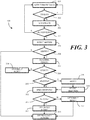
- FIG. 3 illustrated therein is one explanatory method 300 for controlling one or more companion devices in accordance with one or more embodiments of the disclosure.
- a fingerprint sensor detects an object touching the fingerprint sensor.
- one or more processors operable with the fingerprint sensor determine whether the electronic device is docked or stowed.
- embodiments of the disclosure control companion devices in response to biometric or gesture or motion input. Where the electronic device is docked or stowed, embodiments of the disclosure contemplate that gesture or motion within free space is unlikely to occur. Accordingly, where the electronic device is docked or stowed, as determined at decision 302, normal functions - such as actuating the display or launching an application - may be performed rather than any companion device control.
- the method 300 returns to step 301 when the electronic device is docked or stowed.
- step 303 the fingerprint scanner scans the finger to receive fingerprint data from the finger.
- the method 300 further performs an authentication process on the finger as described above. Said differently, in one embodiment, step 303 includes the biometric sensor identifying biometric input to authenticate a user. Where a user is identified from the fingerprint data, the method proceeds to step 305. Otherwise, the method returns to step 301.
- one or more gesture sensors detect one or more gestures.
- the gestures comprise motion of the electronic device itself, as detected by one or more motion sensors.
- the gestures comprise motion of an object near the electronic device, as detected by one or more proximity sensors.
- the one or more proximity sensors may detect a user waving a hand or making another gesture above the electronic device instead of by moving the electronic device itself.
- the method 300 attempts to identify the gesture as a predefined gesture. In one embodiment, this can be accomplished by comparing extracted parametric data from the detected gesture motion and comparing it with a profile stored in memory. Where the gesture is identified or authenticated, the method 300 can continue. However, where the gesture is not authenticated or identified, the method 300 can move to step 313, where the processors of the electronic device take other actions such as informing the person that no predefined gesture has been detected.
- the method 300 moves to step 307 where a number of companion devices operating within a wireless communication radius is determined.
- the method determines whether any companion devices have been detected. Where none have, the method 300 can optionally notify the user through a user interface that no companion devices have been detected at step 314.
- decision 309 determines whether one companion device or multiple companion devices have been detected. Where one, the method method proceeds to step 310. However, where there are multiple companion devices detected, in one embodiment the method 300 optionally notifies the user of this fact at step 315. Methods for providing this notification have been described above with reference to FIG. 2 . At step 316, the method 300 receives a user selection of at least one of the companion devices. Methods for receiving this selection have also been described above.
- the method 300 delivers an actuation credential to at least one companion device.
- the actuation credential can take a number of different forms. In its most basic form, the actuation credential comprises an electronic message commanding or authorizing the companion device to take a particular action. Examples of such actions include turning ON, turning OFF, selecting content to play, fast forwarding, rewinding, skipping, and so forth. The actions will vary based upon the application and the type of companion device.
- the actuation credential can comprise keys or tokens that provide a security or authentication notification.
- the actuation credential may indicate both an action that the companion device should preform and an indication that a particular user has been identified. Other types of actuation credentials will be obvious to those of ordinary art having the benefit of this disclosure.
- the method 300 can determine whether the command set forth in the actuation credential has been successful. For example, the companion device may send an acknowledgement message in response to receiving the actuation credential indicating whether the command was successful. In one or more embodiments, the method 300 may optionally notify the user regarding whether the command set forth in the actuation credential was successful at step 312.
- an electronic device may present a list of the multiple companion devices along its display. A selection can then be received when a user touches a user actuation target corresponding to a particular device. Alternatively, the electronic device may present the list of multiple devices as audible output from a loudspeaker. A selection may be received as voice input through a microphone. Methods for doing either are depicted in FIG. 4 . Still other techniques for providing an identification of the multiple companion devices, and receiving a selection therefrom therefrom of one or more companion devices, will be obvious to those of ordinary skill in the art having the benefit of this disclosure.
- the method 400 detects that multiple companion devices are operable with an electronic device within a wireless communication radius.
- the method 400 communicates with one of the companion devices to obtain its identity.
- step 401 can include transmitting a wireless communication message to a companion device requesting an identifier and then receiving that identifier. As shown at decision 403, this process can repeat until all companion devices have been identified.
- step 402 the method 400 identifies the companion devices to the user.
- step 402 presents a list of the multiple companion devices along its display.
- step 402 presents the list of multiple devices as audible output from a loudspeaker. This step 402 can occur as devices are identified, i.e., each time step 401 is performed, in one embodiment. However, in other embodiments this step 402 can occur once all of the companion devices have been identified, e.g., after decision 403.
- step 404 the method 400 monitors for user input to select one or more of the companion devices.
- step 404 comprises a user touching a user actuation target on a display corresponding to a particular device.
- step 404 receives voice input through a microphone.
- a user selects a single companion device at step 404.
- the user selects multiple devices at step 404.
- a user may select multiple companion devices, for example, where those companion devices are lights or loudspeakers and the user wishes to turn them all ON or OFF simultaneously.
- the user may select a single companion device if, for instance, the company device is a thermostat and the user wants to change the temperature.
- step 404 fan monitor for use touch user input, audio user input, gesture user input, or other user input to determine a selection by a user.
- the method 400 starts a timer at step 405.
- the method 400 can determine whether user input is received. This can continue until the timer expires, as determined at decision 408. Where no user selection is received prior to expiration of the timer, the system can reset at step 409.
- the method 400 can determine if it corresponds to one or more companion devices being selected at decision 407. Where it does, an actuation credential can be delivered to the one or more companion devices to control the same.
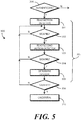
- the method 500 monitors a first motion detector at step 501.
- the first motion detector is an accelerometer. From the parametric data delivered by the accelerometer, the method 500 determines whether the electronic device is moving at decision 502.
- the method 500 can then read a second motion detector at step 503.
- the second motion detector is a gyroscope.
- the method 500 can determine if the electronic device is changing its orientation, e.g., rotating or pivoting, in free space at decision 504.
- decision 504 includes determining if a major axis of the electronic device is changing in excess of a predetermined rate, or whether the major axis has deviated from a predefined reference by more than a predetermined amount.
- Decision 504 may query whether, for example, the "y-axis" reading of the accelerometer is greater than ten or less than minus ten to determine whether the orientation of the electronic device is changing in free space.
- the parametric data from the various motion sensors can be compared to predefined gesture data stored in a memory of the electronic device to determine whether a user is making a predefined gesture. Whether the gesture can be identified is determined at decision 306 as previously described. Where the gesture is identified, an actuation credential is sent at step 310.
- a user 600 places their finger 601 on a fingerprint sensor 104 of an electronic device.
- the fingerprint sensor 104 identifies fingerprint data from the user's finger 601 to authenticate the user.
- the electronic device 100 includes both an application processor (107) and an auxiliary processor (108).
- the auxiliary processor determines 603, through the exchange of wireless communication signals 604 from a wireless communication circuit (109), whether one or more companion devices are in communication with the electronic device within a wireless communication radius 605.
- a notification 606 can be presented on the display 102 to let the user 600 know what is occurring.
- the electronic device 100 has detected two companion devices 701,702 operating within the wireless communication radius (605).
- a first companion device 701 is a music player that is paired with the electronic device 100 by a Bluetooth.sup.TM connection.
- the second companion device 702 is a disco strobe light that is communicating with the electronic device 100 through a router in a Wi-Fi network.
- companion devices 701,702 only. Others will be readily apparent to those of ordinary skill in the art having the benefit of this disclosure.
- the electronic device 100 has detected two companion devices 701,702. As noted above, when this occurs, the electronic device 100 can identify a user selection in a variety of ways. A list of the companion devices 701,702 could be presented on the display from which the user 600 could make a selection by touch. Alternatively, an audible list of the companion devices 701,702 could be delivered through a loudspeaker, with the user 600 making a choice with a voice command.
- the user 600 makes the selection by way of a predefined gesture input. Specifically, as shown in FIG. 7 , the user 600 translates 703 the electronic device 100 in free space 704 from a first position, shown in FIG. 6 , to a second position, shown in FIG. 7 . This orients a major axis 705 of the electronic device 100 toward companion device 701 the user 600 wishes to select. Accordingly, the major axis 705 of the electronic device 100 is effectively pointed toward the music player.
- the auxiliary processor (108) can detect this by determining an orientation of the electronic device 100 in free space 704 and comparing it with a stored map of the room in which the user 600 is located.
- the music player is initially OFF.
- the user 600 can see this because a clock 706 is presented on a display 707 of the music player.
- the user 600 wants to turn the music player ON.
- the user 600 since the user 600 wants to actuate the music player, the user 600 executes a key turn simulation 801 by rotating 802 the electronic device 100 about a major axis 705. This simulates the turning of a key once it is in a lock. This is detected by one or more motion sensors (116). Said differently, the motion sensors (116) of the electronic device 100 detect the predefined gesture 800 translating the electronic device 100 in free space 704 and identify it by comparing parametric data corresponding to the predefined gesture 800 with reference data stored in memory (105).
- the auxiliary processor (108) can control the wireless communication circuit (109) to cause it to wirelessly deliver an actuation credential 803 to the music player.
- this unlocks the companion device 701.
- the actuation credential 803 causes the music player to actuate and start playing "Mac's Boogie Woogie" by the infamous Buster and his Bluesmen.
- the user 600 has not only selected the music player, but has turned it on as well.
- the user 600 selected and unlocked a companion device 701 by orienting a major axis 705 of the electronic device 100 toward the companion device 701 via a translation 703 of the electronic device 100 in free space 704 between a first position ( FIG. 6 ) and a second position ( FIG. 7 ), and rotating 802 the electronic device 100 about the major axis 705 to perform a key turn simulation 801. While this is one option for performing these tasks, embodiments of the disclosure are not so limited. Numerous other techniques have been described above for performing these operations, and numerous others will be obvious to those of ordinary skill in the art having the benefit of this disclosure.
- the user 600 makes a gesture 901 by waving a hand 902 above the electronic device 100.
- the proximity sensors (119) detect this gesture 901 despite the fact that it is above the display 102.
- the predefined gesture input comprises a predefined motion of an object, i.e., the gesture 901 of the user's hand 902), as detected by the one or more proximity sensors (119), about the electronic device 100.
- the auxiliary processor (108) can control the wireless communication circuit (109) to cause it to wirelessly deliver an actuation credential 803 to the music player.
- the auxiliary processor (108) optionally provides a notification 903 on a user interface, e.g. the display 102 in this example, that the actuation credential 803 was delivered by the wireless communication circuit (109) of the electronic device.
- FIGS. 6-8 Regardless of whether the method of FIGS. 6-8 , or the method of FIG. 9 , or another method is used to unlock the music player, presume now that the user 600 wishes to turn on the disco strobe light. In one embodiment, the user 600 can do this by making a different gesture than that made in either FIGS. 6-8 or FIG. 9 .
- the user 600 since the music player is ON, the user 600 wishes to turn on the disco strobe light. After orienting the major axis (705) of the electronic device 100 toward companion device 702 the user 600 wishes to select, as occurred in FIG. 7 , rather than making a key turn simulation (801), the user 600 makes a snap back motion, which the auxiliary processor (108), from the motion sensors (116) will identify as being associated with the disco strobe light.
- the user 600 first translates 1001 the electronic device 100 back to a first position 1002. As shown in FIG. 11 , the user then translates 1101 the electronic device 100 to a second position 1102, thereby actuating the disco strobe light so that a club-type atmosphere is invoked to enhance the joy that the catalog of Buster and his Bluesmen.
- the gesture (800) of FIG. 8 and the gesture of FIGS. 10-11 occurred after the user's finger (601) was removed from the fingerprint sensor (104).
- embodiments of the disclosure are not so limited.
- the method steps set forth in FIGS. 6-8 or FIGS. 10-11 could have also been performed while the finger (601) was on the fingerprint sensor (104) as well.
- the gesture sensors identify a predefined gesture such as gesture (800) while the fingerprint sensor (104) receives fingerprint data from the finger (601). In one or more embodiments, this can make the intuitive gesture used to control the companion devices (701,702) faster.
- FIGS. 10-12 illustrated therein are different method steps for selecting a companion device when multiple companion devices 701,702 are operating within a wireless communication radius of an electronic device 100.
- a user 600 places their finger 601 on a fingerprint sensor 104 of an electronic device 100.
- the fingerprint sensor 104 identifies fingerprint data from the user's finger 601 to authenticate the user.
- the electronic device 100 has detected two companion devices 701,702 operating within the wireless communication radius (605). The first is the music player and the second is the disco strobe lamp.
- the auxiliary processor (108) of the electronic device 100 then presents identification 1303 of the companion devices 701,702 on the user interface of the electronic device 100.
- the identification 1303 is a textual listing 1301 of the various companion devices 701,702 presented on the display 102 of the electronic device 100.
- the user 600 is then able to make a user selection 1302 of one or more of the companion devices 701,702 by touching user actuation targets corresponding to the companion devices 701,702.
- the user 600 has selected both the music player and the disco strobe light because he desires both to come on simultaneously.
- the user 600 then executes the key turn simulation (801) as previously described.
- This causes the wireless communication circuit (109) operating in the electronic device 100, which is responsive to the auxiliary processor (108), to deliver an actuation credential to both companion devices (701,702) upon the one or more gesture sensors identifying the predefined gesture input defined by the key turn simulation (801). As shown in FIG. 12 , this causes both companion devices 701,702 to actuate.
- embodiments of the disclosure provides a secure and fast way to to lock, unlock, or otherwise control a wireless companion device.
- Embodiments of the disclosure can be used to provide multiple users with a method to authenticate and lock, unlock, or otherwise otherwise control their specific wireless devices.
- Embodiments of the disclosure provide multiple users with a method to authenticate and lock, unlock, or otherwise define specific access levels on a shared wireless device.
- Embodiments of the disclosure provide a method for users to lock, unlock, or otherwise control a specific wireless devices when multiple devices are detected.
- embodiments of the disclosure provide a quick and intuitive technique to control companion devices.
- a user simply places their finger on a biometric sensor and performs a predefined gesture either after taking their finger off the biometric sensor or while the finger is on the biometric sensor. This simple key twist simulation is all that is required to control companion devices in an intuitive, simple manner.
Landscapes
- Engineering & Computer Science (AREA)
- Theoretical Computer Science (AREA)
- General Engineering & Computer Science (AREA)
- Physics & Mathematics (AREA)
- General Physics & Mathematics (AREA)
- Computer Security & Cryptography (AREA)
- Human Computer Interaction (AREA)
- Computer Networks & Wireless Communication (AREA)
- Signal Processing (AREA)
- Computer Hardware Design (AREA)
- Software Systems (AREA)
- User Interface Of Digital Computer (AREA)
Abstract
Description
- This disclosure relates generally to electronic devices, and more particularly to portable electronic devices with motion sensors.
- Mobile electronic communication devices are used by billions of people. The owners of such devices use them for many different purposes including, but not limited to, voice communications, text messaging, Internet browsing, calendar management, commerce such as banking, and social networking.
- As these devices become more sophisticated, they can also become more complicated to operate. Illustrating by example, many "smart devices" now come equipped with touch sensitive displays rather than physical keyboards. While touching a surface is considered by some to be a simpler operation than working a complex keyboard, executing complex operations can require the navigation of several different menu tiers or user interface levels.
- It would be advantageous to have simplified systems and methods for executing complex operations in modern electronic devices.
-
-
FIG. 1 illustrates one explanatory electronic device in accordance with one or more embodiments of the disclosure. -
FIG. 2 illustrates one explanatory schematic block diagram with corresponding functional operations in accordance with one or more embodiments of the disclosure. -
FIG. 3 illustrates one explanatory method in accordance with one or more embodiments of the disclosure. -
FIG. 4 illustrates another explanatory method in accordance with one or more embodiments of the disclosure. -
FIG. 5 illustrates yet another explanatory method in accordance with one or more embodiments of the disclosure. -
FIG. 6 illustrates one or more method steps for an explanatory system in accordance with one or more embodiments of the disclosure. -
FIG. 7 illustrates one or more method steps for an explanatory system in accordance with one or more embodiments of the disclosure. -
FIG. 8 illustrates one or more method steps for an explanatory system in accordance with one or more embodiments of the disclosure. -
FIG. 9 illustrates one or more method steps for an explanatory system in accordance with one or more embodiments of the disclosure. -
FIG. 10 illustrates one or more method steps for an explanatory system in accordance with one or more embodiments of the disclosure. -
FIG. 11 illustrates one or more method steps for an explanatory system in accordance with one or more embodiments of the disclosure. -
FIG. 12 illustrates one or more method steps for an explanatory system in accordance with one or more embodiments of the disclosure. -
FIG. 13 illustrates one or more method steps for an explanatory system in accordance with one or more embodiments of the disclosure. -
FIG. 14 illustrates one or more method steps for an explanatory system in accordance with one or more embodiments of the disclosure. - Skilled artisans will appreciate that elements in the figures are illustrated for simplicity and clarity and have not necessarily been drawn to scale. For example, the dimensions of some of the elements in the figures may be exaggerated relative to other elements to help to improve understanding of embodiments of the present disclosure.
- Before describing in detail embodiments that are in accordance with the present disclosure, it should be observed that the embodiments reside primarily in combinations of method steps and apparatus components related to using biometric and/or motion or proximity sensors to control modes of operation of an electronic device, and in particular to wirelessly actuate companion devices that are operable with the electronic device. Any process descriptions or blocks in flow charts should be understood as representing modules, segments, or portions of code that include one or more executable instructions for implementing specific logical functions or steps in the process.
- Embodiments of the disclosure do not recite the implementation of any commonplace business method aimed at processing business information, nor do they apply a known business process to the particular technological environment of the Internet. Moreover, embodiments of the disclosure do not create or alter contractual relations using generic computer functions and conventional network operations. Quite to the contrary, embodiments of the disclosure employ methods operable on hardware platforms that, when applied to electronic device and/or user interface technology, improve the functioning of the electronic device itself by simplifying companion device actuation to improve the overall user experience by overcoming problems specifically arising in the realm of the recently developed technology associated with electronic device user interaction.
- Alternate implementations are included, and it will be clear that functions may be executed out of order from that shown or discussed, including substantially concurrently or in reverse order, depending on the functionality involved. Accordingly, the apparatus components and method steps have been represented where appropriate by conventional symbols in the drawings, showing only those specific details that are pertinent to understanding the embodiments of the present disclosure so as not to obscure the disclosure with details that will be readily apparent to those of ordinary skill in the art having the benefit of the description herein.
- It will be appreciated that embodiments of the disclosure described herein may be comprised of one or more conventional processors and unique stored program instructions that control the one or more processors to implement, in conjunction with certain non-processor circuits, some, most, or all of the functions of controlling companion devices in response to biometric or gesture or motion input as described herein. The non-processor circuits may include, but are not limited to, a radio receiver, a radio transmitter, signal drivers, clock circuits, power source circuits, and other user input devices. As such, these functions may be interpreted as steps of a method to perform device control companion devices in response to one or more biometric, proximity, and/or motion sensors components. Alternatively, some or all functions could be implemented by a state machine that has no stored program instructions, or in one or more application specific integrated circuits (ASICs), in which each function or some combinations of certain of the functions are implemented as custom logic. Of course, a combination of the two approaches could be used. Thus, methods and means for these functions have been described herein. Further, it is expected that one of ordinary skill, notwithstanding possibly significant effort and many design choices motivated by, for example, available time, current technology, and economic considerations, when guided by the concepts and principles disclosed herein will be readily capable of generating such software instructions and programs and ASICs with minimal experimentation.
- Embodiments of the disclosure are now described in detail. Referring to the drawings, like numbers indicate like parts throughout the views. As used in the description herein and throughout the claims, the following terms take the meanings explicitly associated herein, unless the context clearly dictates otherwise: the meaning of "a," "an," and "the" includes plural reference, the meaning of "in" includes "in" and "on." Relational terms such as first and second, top and bottom, and the like may be used solely to distinguish one entity or action from another entity or action without necessarily requiring or implying any actual such relationship or order between such entities or actions. Also, reference designators shown herein in parenthesis indicate components shown in a figure other than the one in discussion. For example, talking about a device (10) while discussing figure A would refer to an element, 10, shown in figure other than figure A.
- Embodiments of the disclosure provide secure and simple methods of unlocking, actuating, or otherwise controlling companion devices that are operable with an electronic device. Examples of companion devices include music players, televisions, media players, lights, thermostats, appliances, locks, and so forth. For example, embodiments of the disclosure provide secure and simple methods of controlling a music player that is in wireless communication with an electronic device. In one embodiment, a user can identify themself using a fingerprint sensor. Upon authentication of identification, a user can make a "key turn" simulation gesture to, for instance, turn on a music player operating within a wireless communication radius of the electronic device. Advantageously, this eliminates the need for a user to navigate to an application, and through the application, which may require several touches or user interactions with the display, to perform the same operation.
- In one or more embodiments, an electronic device includes a biometric sensor, one example of which is a fingerprint sensor. The biometric sensor is responsible for identifying biometric input received at the biometric sensor. One or more processors, which are operable with the biometric sensor, then identify one or more companion devices operating within a wireless communication radius of the electronic device. As noted above, the companion devices can include music players, wirelessly connected home devices and appliances, health trackers, tools, and so forth.
- Once the user is identified from the biometric input, in one embodiment one or more gesture sensors identify a predefined gesture input. The gesture sensors can include motion detectors, proximity detectors, or combinations thereof. One example of a predefined gesture input would be where the user holds the electronic device as if it were a key positioned within a lock, and then twists the electronic device about a major axis. In one embodiment, when this occurs, and the one or more gesture sensors identify the gesture as the predefined gesture input, a wireless communication circuit responsive to the one or more processors delivers an actuation credential to the one companion device. The actuation credential can actuate the companion device, control the companion device, deactuate the companion device, or perform other control operations. Thus, in one embodiment, a user touches a fingerprint sensor and twists the electronic device with a key turn simulation as if it were a key in a lock to actuate a wireless music player to start enjoying smooth jazz during cocktail hour.
- Advantageously, embodiments of the disclosure provide a secure and fast way to lock, unlock, actuate, deactuate, or otherwise control a companion device. Where multiple companion devices are operating within the wireless communication radius, embodiments of the disclosure provide methods and systems for selecting between the various devices. Illustrating by example, in one embodiment a list of companion devices is presented on the display from which a user can select a single device prior to making the gesture. In another embodiment, an audible or other notification that there are multiple companion devices paired with the electronic device is delivered, from which a user may deliver an audible command such as "control the music player" prior to making the gesture. Other techniques for alerting the user to the fact that there are multiple companion devices operating within the predefined wireless radius will be obvious to those of ordinary skill in the art having the benefit of this disclosure.
- In one or more embodiments, a combination of biometric authentication and gesture control is used to control a companion device. Advantageously, the use of biometric authentication allows multiple users of a single device to control their specific companion devices. Illustrating by example, if a family uses one tablet computer, the one or more processors operating within the tablet computer can identify the family member though biometric identification, thereby allowing the user to control their specific devices without controlling another family member's companion devices. Moreover, the biometric authentication also advantageously allows multiple users of a single electronic device to control differing access levels on a companion device. For instance, parents may not want their children to listen to heavy metal music. Accordingly, when a child is identified, they may be allowed to control a music player, but only to play jazz, bluegrass, or classical music. By contrast, when the biometric sensor identifies a parent, they may be able to control the music player to listen to bone-crushing metal like there is no tomorrow. Other advantages of embodiments of the disclosure will be obvious to those of ordinary skill in the art having the benefit of this disclosure.
- In one or more embodiments, the one or more processors executing the operations corresponding to interaction with the biometric sensor, the one or more gesture sensors, and the wireless communication circuit is a low-power, auxiliary processor. As will be described in more detail below, in one or more embodiments an electronic device is equipped with an application processor an auxiliary processor. As used herein, an "application" processor is configured to operate the primary applications of the electronic device, including the operating system environment. A "secondary" or "auxiliary" processor can be configured to operate ancillary or secondary functions. However, in one or more embodiments the auxiliary processor is operable with the biometric sensor, the one or more gesture sensors, and the wireless communication circuit to control companion devices operating within a predefined wireless communication radius in response to biometric input and gesture detection.
- In one or more embodiments, the auxiliary processor is a low power processor having lower power consumption than the application processor. For example, in one embodiment the application processor is tasked with providing the operating system environment and for performing application operating functions of an electronic device. Accordingly, the application processor will consume relatively large amounts of power. By contrast, the auxiliary processor may perform a limited number of functions including, but not limited to, controlling companion devices operating within a predefined wireless communication radius in response to biometric input and gesture detection. Thus, in one or more embodiments the auxiliary processor is configured as a smaller component that consumes less power than an application processor. Biometric sensors, gesture sensors, and wireless communication circuits in accordance with embodiments of the disclosure can be configured to work with either device. However, in one or more embodiments control of companion devices in response to biometric and gesture input is advantageously performed by the auxiliary process to save power and extend operational run time of the electronic device. Embodiments of the disclosure contemplate that power savings - and thus longer runtime on a single battery charge - can be achieved by using the auxiliary processor, rather than the application processor, to control companion device operations.
- Thus, in one or more embodiments an electronic device includes a biometric sensor such as a fingerprint sensor responsible for identifying fingerprint data. The electronic device can include an application processor and an auxiliary processor, where the auxiliary processor consumes less power than the application processor. In one or more embodiments, the auxiliary processor is configured to determine, with a wireless communication circuit, one or more companion devices in communication with the electronic device. One or more motion sensors, operable with the auxiliary processors, are then responsible for detecting a predefined gesture translating the electronic device in free space. When this occurs, the wireless communication circuit delivers an actuation credential to at least one companion device in response to the one or more motion sensors detecting the predefined gesture.
- Turning now to
FIG. 1 , illustrated therein is one explanatoryelectronic device 100 configured in accordance with one or more embodiments of the disclosure. Theelectronic device 100 ofFIG. 1 is a portable electronic device, and is shown as a smart phone for illustrative purposes. However, it should be obvious to those of ordinary skill in the art having the benefit of this disclosure that other electronic devices may be substituted for the explanatory smart phone ofFIG. 1 . For example, theelectronic device 100 could equally be a palm-top computer, a tablet computer, a gaming device, a media player, or other wireless communication device. - This illustrative
electronic device 100 includes adisplay 102, which in one embodiment is touch-sensitive and defines a primary user interface for theelectronic device 100. Users can deliver user input to thedisplay 102 of such an embodiment by delivering touch input from a finger, stylus, or other objects disposed proximately with the display. In one embodiment, thedisplay 102 is configured as an organic light emitting diode (OLED) display fabricated on a flexible plastic substrate. However, it should be noted that other types of displays would be obvious to those of ordinary skill in the art having the benefit of this disclosure. - The explanatory
electronic device 100 ofFIG. 1 includes ahousing 101. Features can be incorporated into thehousing 101. In this illustrative embodiment, abiometric sensor 103 disposed along a surface of thehousing 101. In one embodiment thebiometric sensor 103 is responsible for identifying biometric input received at thebiometric sensor 103 to authenticate or otherwise identify a user. Other devices can be disposed along thehousing 101 as well. Examples of such devices include an optional camera or speaker port for an audio output device. - In one embodiment, the
biometric sensor 103 is afingerprint sensor 104. However, other types of biometric sensors that can be substituted for thefingerprint sensor 104 will be obvious to those of ordinary skill in the art having the benefit of this disclosure. For example, in other embodiments thebiometric sensor 103 can be a voice interface engine. The voice interface engine can include hardware, executable code, and speech monitor executable code in one embodiment. The voice interface engine can include, stored inmemory 105, basic speech models, trained speech models, or other modules that are used by the voice interface engine to receive and identify a particular user's voice commands that are received with audio input captured by an audio capture device. In one embodiment, the voice interface engine can include a voice recognition engine. - In another embodiment, the
biometric sensor 103 can be an image/gaze detection-processing engine. The image/gaze detection-processing engine can be operable with physical sensors, such as a camera or intelligent imager, to process information detected from a user's gaze to identify the user through facial, eye, or other recognition techniques. The image/gaze detection-processing engine can also be configured to identify the user through facial recognition techniques by capturing photographs of the user. Other examples ofbiometric sensors 103 suitable for use with embodiments of the disclosure will be obvious to those of ordinary skill in the art having the benefit of this disclosure. - In one embodiment, the
fingerprint sensor 104 includes its own processor to perform various functions, including detecting a finger touching thefingerprint sensor 104, capturing and storing fingerprint data from the finger, and optionally identifying or authenticating a user based upon the fingerprint data. In one or more embodiments the processor of thefingerprint sensor 104 can, as one pre-processing step, perform a preliminary authentication of the user by comparing fingerprint data captured by thefingerprint sensor 104 to a reference file stored inmemory 105, while secondary authentication is performed by theapplication processor 107 orauxiliary processor 108. The processor of thefingerprint sensor 104 can be an on-board processor. Alternatively, the processor can be a secondary processor that is external to, but operable with, the fingerprint sensor in another embodiment. One example of which is the auxiliary processor - 108. Other configurations will be obvious to those of ordinary skill in the art having the benefit of this disclosure.
- In one embodiment, the
fingerprint sensor 104 can include a plurality of sensors. Thefingerprint sensor 104 can be a complementary metal-oxide-semiconductor active pixel sensor digital imager or any other fingerprint sensor. Thefingerprint sensor 104 can be configured to capture, with the plurality of sensors, a live scan of a fingerprint pattern from a finger disposed along its surface, and to store this information as fingerprint data from the user's finger. Thefingerprint sensor 104 may also be able to capture one or more images with the plurality of sensors. The images can correspond to an area beneath a surface of skin. Thefingerprint sensor 104 can compare the fingerprint data or skin images to one or more references to authenticate a user in an authentication process. - While the
biometric sensor 103 is disposed along a front surface of thehousing 101 in this illustration, it should be noted that it could alternatively be disposed along the rear surface of thehousing 101 in other embodiments. In still other embodiments, thebiometric sensor 103 could be disposed beneath thedisplay 102, thereby allowing the user to place a finger on thedisplay 102 for identification. - In one embodiment, where the
biometric sensor 103 is afingerprint sensor 104, thefingerprint sensor 104 can be a single function device. In other embodiments, thefingerprint sensor 104 can be a dual or multifunction device. Illustrating by example, in one embodiment thefingerprint sensor 104 is solely responsible for receiving biometric data from a user and either authenticating the user or determining that the user is unauthorized to use theelectronic device 100. This would be a single function fingerprint sensor. - In other embodiments, the
fingerprint sensor 104 may be capable of performing multiple functions. Again illustrating by example, in one embodiment thefingerprint sensor 104 can receive biometric data from a user and either authenticate the user or determine that the user is unauthorized to use theelectronic device 100. However, thefingerprint sensor 104 may also be configured as a push button. Thus, by touching thefingerprint sensor 104 the user may deliver biometric data only. However, by touching and pressing thefingerprint sensor 104, thefingerprint fingerprint sensor 104 may both authenticate the user by receiving the biometric data from touch input and perform a second function in response to the push button being depressed. - A
block diagram schematic 106 of theelectronic device 100 is also shown inFIG. 1 . In one embodiment, theelectronic device 100 includes one or more processors. In one embodiment, the electronic device includes anapplication processor 107 and anauxiliary processor 108. One or both of theapplication processor 107 or theauxiliary processor 108 can include one or more processors. One or both of theapplication processor 107 or theauxiliary processor 108 can be a microprocessor, a group of processing components, one or more Application Specific Integrated Circuits (ASICs), programmable logic, or other type of processing device. Theapplication processor 107 and theauxiliary processor 108 can be operable with the various components of theelectronic device 100. Each of theapplication processor 107 and theauxiliary processor 108 can be configured to process and execute executable software code to perform the various functions of theelectronic device 100. A storage device, such asmemory 105, can optionally store the executable software code used by theapplication processor 107 or theauxiliary processor 108 during operation. - As noted above, in one or more embodiments the
auxiliary processor 108 is a low power processor having lower power consumption than theapplication processor 107. For example, in one embodiment theapplication processor 107 is tasked with providing the operating system environment and for running various applications operating on theelectronic device 100. Accordingly, theapplication processor 107 can consume relatively large amounts of power. - For example, in one embodiment, the
application processor 107 is responsible for running the operating system environment 111. The operating system environment 111 can include akernel 112 and one or more drivers, and anapplication service layer 113, and anapplication layer 114. The operating system environment 111 can be configured as executable code stored inmemory 105. - The
application layer 114 can be responsible for executing application service modules. The application service modules may support one or more applications or "apps." The applications of theapplication layer 114 can be configured as clients of theapplication service layer 113 to communicate with services through application program interfaces (APIs), messages, events, or other inter-process communication interfaces. - By contrast, the
auxiliary processor 108 may perform a limited number of functions including, but not limited to, controlling companion devices operating within a predefined wireless communication radius in response to biometric input and gesture detection. Thus, in one or more embodiments theauxiliary processor 108 is configured as a smaller component that consumes less power than anapplication processor 107. Where control of companion devices in response to biometric and gesture input is advantageously performed by theauxiliary processor 108, this saves power and extends operational run time of theelectronic device 100. Advantageously, power savings are achieved by using theauxiliary processor 108, rather than theapplication processor 107, to control companion device operations in one or more embodiments. - In this illustrative embodiment, the
electronic device 100 also includes a wireless communication circuit 109 that can be configured for wired or wireless communication with one or more companion devices operating within a predefined wireless communication radius. The wireless communication circuit 109 can also be operable to communicate across one or more networks. The networks can include a wide area network, a local area network, and/or personal area network. Examples of wide area networks include GSM, CDMA, W-CDMA, CDMA-2000, iDEN, TDMA, 2.5 Generation 3GPP GSM networks, 3rd Generation 3GPP WCDMA networks, 3GPP Long Term Evolution (LTE) networks, and 3GPP2 CDMA communication networks, UMTS networks, E-UTRA networks, GPRS networks, iDEN networks, and other networks. - The wireless communication circuit 109, in one embodiment, may also utilize wireless technology for communication across networks having a limited wireless communication radius. Such networks include, but are not limited to, peer-to-peer or ad hoc communications such as HomeRF, Bluetooth and IEEE 802.11 (a, b, g or n), and other forms of wireless communication such as infrared technology. The wireless communication circuit 109 can include wireless communication circuitry, one of a receiver, a transmitter, or transceiver, and one or
more antennas 110. - One or more other sensors 115 can be operable with one or more of the
application processor 107, theauxiliary processor 108, or combinations thereof. In one embodiment, the other sensors 115 includemotion sensors 116. Themotion sensors 116 can include one ormore accelerometers 117 or gyroscopes 1118. For example, anaccelerometer 117 may be embedded in the electronic circuitry of theelectronic device 100 to show vertical orientation, constant tilt and/or whether theelectronic device 100 is stationary. The measurement of tilt relative to gravity is referred to as "static acceleration," while the measurement of motion and/or vibration is referred to as "dynamic acceleration." Agyroscope 118 can be used in a similar fashion. An altimeter can be included as one of themotion sensors 116 as well. - Regardless of the type of
motion sensors 116 that are used, in one embodiment themotion sensors 116 are also operable to detect movement, and direction of movement, of theelectronic device 100 by a user. In one or more embodiments, the other sensors 115 and themotion sensors 116 can each be used to detect motion when a user pivots, rotates, elevates, translates, or otherwise moves theelectronic device 100. This information can be used to identify whether the user is executing a motion corresponding to a predefined gesture. Accordingly, in one one or more embodiments, themotion sensors 116 and/orproximity sensors 119 are collectively referred to as "gesture sensors." - Illustrating by example, in one embodiment when the
electronic device 100 is held in a user's hand, the user may make certain movements in free space such as that of performing a key turn simulation. Themotion sensors 116 can be used to detect such motions and to determine whether they correspond to predefined gesture profiles stored inmemory 105. In one embodiment, theauxiliary processor 108 then extracts parametric data from electronic signals delivered by thesemotion sensors 116. By comparing the parametric data to a reference file stored inmemory 105, theauxiliary processor 108 can identify whether the user's motion in free space corresponds to a predefined gesture. Theauxiliary processor 108 can use this information to control one or more companion devices as will be described in more detail below. - In one or more embodiments, the other sensors 115 also include one or
more proximity sensors 119. In one embodiment, the one ormore proximity sensors 119 include one or moreproximity sensor components 120. Theproximity sensors 119 can also include one or moreproximity detector components 121. In one embodiment, theproximity sensor components 120 comprise only signal receivers. By contrast, theproximity detector components 121 include a signal receiver and a corresponding signal transmitter. - While each proximity detector component can be any one of various types of proximity sensors, such as but not limited to, capacitive, magnetic, inductive, optical/photoelectric, imager, laser, acoustic/sonic, radar-based, Doppler-based, thermal, and radiation-based proximity sensors, in one or more embodiments the proximity detector components comprise infrared transmitters and receivers. The infrared transmitters are configured, in one embodiment, to transmit infrared signals having wavelengths of about 860 nanometers, which is one to two orders of magnitude shorter than the wavelengths received by the proximity sensor components. The proximity detector components can have signal receivers that receive similar wavelengths, i.e., about 860 nanometers.
- In one or more embodiments the proximity sensor components have a longer detection range than do the proximity detector components due to the fact that the proximity sensor components detect heat directly emanating from a person's body (as opposed to reflecting off the person's body) while the proximity detector components rely upon reflections of infrared light emitted from the signal transmitter. For example, the proximity sensor component may be able to detect a person's body heat from a distance of about ten feet, while the signal receiver of the proximity detector component may only be able to detect reflected signals from the transmitter at a distance of about one to two feet.
- In one embodiment, the
proximity sensor component 120 comprises an infrared signal receiver so as to be able to detect infrared emissions from a person. Accordingly, theproximity sensor component 120 requires no transmitter since objects disposed external to thehousing 101 deliver emissions that are received by the infrared receiver. As no transmitter is required, eachproximity sensor component 120 can operate at a very low power level. Such infrared signal receivers can operate with a total current drain of just a few microamps (∼10 microamps per sensor). By contrast, aproximity detector component 121, which includes a signal transmitter, may draw hundreds of microamps to a few milliamps. - In one embodiment, one or more proximity detector components 121can each include a signal receiver and a corresponding signal transmitter. The signal transmitter can transmit a beam of infrared light that reflects from a nearby object and is received by a corresponding signal receiver. The
proximity detector components 121 can be used, for example, to compute the distance to any nearby object from characteristics associated with the reflected signals. The reflected signals are detected by the corresponding signal receiver, which may be an infrared photodiode used to detect reflected light emitting diode (LED) light, respond to modulated infrared signals, and/or perform triangulation of received infrared signals. The reflected signals can also be used to receive user input from a user delivering touch or gesture input to theelectronic device 100. - In one embodiment, the
auxiliary processor 108 may generate commands or execute control operations based on information received from themotion sensors 116, the one ormore proximity sensors 119, thefingerprint sensor 104 or otherbiometric sensor 103, or combinations thereof. Theauxiliary processor 108 may also generate commands or execute control operations based upon information received from one or a combination of these sensors. Moreover, theauxiliary processor 108 may process the received sensor information alone or in combination with other data, such as the information stored in thememory 105. - The one or more other sensors 115 may additionally include a microphone, an earpiece speaker, a second loudspeaker, and/or a component of a
user interface 122, such as a button. The one or more other sensors 115 may also include key selection sensors, a touch pad sensor, a touch screen sensor, a capacitive touch sensor, and one or more switches. Touch sensors may used to indicate whether any of the user actuation targets present on thedisplay 102 are being actuated. Alternatively, touch sensors disposed in thehousing 101 can be used to determine whether theelectronic device 100 is being touched at side edges or major faces of theelectronic device 100 are being performed by a user. The touch sensors can include surface and/or housing capacitive sensors in one embodiment. The other sensors 115 can also include audio sensors and video sensors (such as a camera). - Many of the sensors in the
electronic device 100 can be used to detect movement, gestures, or other user input. For example, the one ormore proximity sensors 119 can detect the gesture of a user waving a hand above thedisplay 102. In another embodiment, the user can deliver gesture input by touching thedisplay 102. In yet another embodiment, theaccelerometer 117 can detect gesture input from a user lifting, shaking, translating, rotating, pivoting, or otherwise deliberately moving theelectronic device 100. In yet other embodiments, the user can deliver gesture input by rotating or changing the orientation of theelectronic device 100, which can be detected bymultiple accelerometers 117 or agyroscope 118. It should be clear to those of ordinary skill in the art having the benefit of this disclosure that additional sensors can be included with the other sensors shown inFIG. 1 . - A
timer 123 can be operable with one or more of theapplication processor 107 or theauxiliary processor 108. One or both of theapplication processor 107 or theauxiliary processor 108 can initiate thetimer 123 during control operations or method steps. When thetimer 123, in one embodiment one or more of theapplication processor 107 or theauxiliary processor 108 can perform certain control operations when events do, or do not, transpire prior to expiration of thetimer 123. Other uses for thetimer 123 will be obvious to those of ordinary skill in the art having the benefit of this disclosure. - It is to be understood that
FIG. 1 is provided for illustrative purposes only and for illustrating components of oneelectronic device 100 in accordance with embodiments of the disclosure, and is not intended to be a complete schematic diagram of the various components required for an electronic device. Therefore, other electronic devices in accordance with embodiments of the disclosure may include various other components not shown inFIG. 1 , or may include a combination of two or more components or a division of a particular component into two or more separate components, and still be within the scope of the present disclosure. - Turning now to
FIG. 2 , illustrated therein are some of the interactions that can occur between thefingerprint sensor 104 and theauxiliary processor 108 in accordance with one or more embodiments of the disclosure. It should be noted that where noauxiliary processor 108 is included, the auxiliary processor functions shown inFIG. 2 can be performed by the application processor (107) of the electronic device (100) instead. Similarly, where anauxiliary processor 108 is included, but is tasked with performing other operations, the application processor (107) of the electronic device (100) can optionally perform one or more of the auxiliary processor functions shown inFIG. 2 as well. - In one embodiment, the
fingerprint sensor 104 is to detect 201 a finger proximately located with thefingerprint sensor 104. As a part of the detection process, thefingerprint sensor 104 can enter an input reception mode upon an object contacting the surface of thefingerprint sensor 104. - In one embodiment, the
fingerprint sensor 104 can optionally be configured to determine 202 that the object touching or otherwise proximately located with thefingerprint sensor 104 is actually a finger and not an object incapable of authentication. Where the object is a finger, thefingerprint sensor 104 can then capture 203 fingerprint data from the finger and perform other pre-processing such as noise filtering and so forth. - In one or more embodiments, the
fingerprint sensor 104 is further to authenticate or identify 204 a user from the fingerprint data received at 203. This step can optionally be performed by theauxiliary processor 108 as well. For example, in one embodiment, one of thefingerprint sensor 104 or theauxiliary processor 108 can perform a matching function. Thefingerprint sensor 104 or theauxiliary processor 108, after having received the fingerprint data, can then perform a matching process to determine whether the fingerprint data substantially matches reference data stored in memory. In one embodiment, upon receiving a request from theauxiliary processor 108 for the fingerprint data, thefingerprint sensor 104 can deliver 205 the fingerprint data to theauxiliary processor 108. - The
auxiliary processor 108, meanwhile, can work with the wireless communication circuit (109) to be responsible for identifying 206 one or more companion devices operating within a wireless communication radius of the electronic device (100). "Companion devices" refer to devices that are in communication with, or alternatively are paired with using a local area network protocol such as Bluetooth.sup.TM, with the electronic device (100). - In some situations, the
auxiliary processor 108 will identify 206 multiple companion devices operating within the wireless communication radius defined by the particular protocol with which the wireless communication circuit (109) is communicating. Where this is the case, theauxiliary processor 108 can optionally provide 207 an identification of the multiple companion devices with a user interface (122) of the electronic device (100). Illustrating by example, in one embodiment theauxiliary processor 108 can present a list of the multiple companion devices along the display (102). In another embodiment, theauxiliary processor 108 can deliver identification of the multiple companion devices audibly through a loudspeaker. Still other techniques for providing 207 an identification of the multiple companion devices will be obvious to those of ordinary skill in the art having the benefit of this disclosure. - Upon identifying multiple companion devices operating within the wireless communication radius, the
auxiliary processor 108 can receive 208 a user selection of the at least one companion device. As with the identification of the multiple companion devices, theauxiliary processor 108 can receive 208 the selection in various ways. In one embodiment, where theauxiliary processor 108 presents a list of the multiple companion devices along the display (102), a selection can be received 208 when a user touches a user actuation target corresponding to a particular device. In another embodiment, where theauxiliary processor 108 delivers the identification of the multiple companion devices audibly through a loudspeaker, theauxiliary processor 108 may receive the selection as voice input through a microphone. In still other embodiments, different predefined gestures may be assigned to different companion devices. Accordingly, a user may make a selection by executing one predetermined gesture instead of another predetermined gesture. Other techniques for receiving 208 a selection of one companion device from an identification of multiple companion devices will be obvious to those of ordinary skill in the art having the benefit of this disclosure. - The
auxiliary processor 108 can also, working in tandem with the one or more gesture sensors, be they motion sensors (116), proximity sensors (119), or other sensors, monitor for and identify 209 a predefined gesture. Where this occurs, the auxiliary processor can cause the wireless communication circuit (109) to deliver 210 an actuation credential to at least one companion device upon the one or more gesture sensors and/or auxiliary processor identifying 209 the predefined gesture input. This process will be explained in more detail below with reference to the remaining figures. - Now that the various hardware components have been described, attention will be turned to methods and use cases in accordance with one or more embodiments of the disclosure. Turning now to
FIG. 3 , illustrated therein is oneexplanatory method 300 for controlling one or more companion devices in accordance with one or more embodiments of the disclosure. - At step 301 a fingerprint sensor detects an object touching the fingerprint sensor. At
decision 302, one or more processors operable with the fingerprint sensor determine whether the electronic device is docked or stowed. As noted above, embodiments of the disclosure control companion devices in response to biometric or gesture or motion input. Where the electronic device is docked or stowed, embodiments of the disclosure contemplate that gesture or motion within free space is unlikely to occur. Accordingly, where the electronic device is docked or stowed, as determined atdecision 302, normal functions - such as actuating the display or launching an application - may be performed rather than any companion device control. Thus, whereoptional decision 302 is included, in one embodiment themethod 300 returns to step 301 when the electronic device is docked or stowed. - At
step 303, the fingerprint scanner scans the finger to receive fingerprint data from the finger. Atstep 303, themethod 300 further performs an authentication process on the finger as described above. Said differently, in one embodiment,step 303 includes the biometric sensor identifying biometric input to authenticate a user. Where a user is identified from the fingerprint data, the method proceeds to step 305. Otherwise, the method returns to step 301. - At
step 305, one or more gesture sensors detect one or more gestures. In one embodiment, the gestures comprise motion of the electronic device itself, as detected by one or more motion sensors. In other embodiments, the gestures comprise motion of an object near the electronic device, as detected by one or more proximity sensors. For example, in the latter case the one or more proximity sensors may detect a user waving a hand or making another gesture above the electronic device instead of by moving the electronic device itself. - At
decision 306, themethod 300 attempts to identify the gesture as a predefined gesture. In one embodiment, this can be accomplished by comparing extracted parametric data from the detected gesture motion and comparing it with a profile stored in memory. Where the gesture is identified or authenticated, themethod 300 can continue. However, where the gesture is not authenticated or identified, themethod 300 can move to step 313, where the processors of the electronic device take other actions such as informing the person that no predefined gesture has been detected. - Assuming the user is identified, in one embodiment the
method 300 moves to step 307 where a number of companion devices operating within a wireless communication radius is determined. Atdecision 308, the method determines whether any companion devices have been detected. Where none have, themethod 300 can optionally notify the user through a user interface that no companion devices have been detected atstep 314. - Where at least one companion device has been detected,
decision 309 determines whether one companion device or multiple companion devices have been detected. Where one, the method method proceeds to step 310. However, where there are multiple companion devices detected, in one embodiment themethod 300 optionally notifies the user of this fact atstep 315. Methods for providing this notification have been described above with reference toFIG. 2 . Atstep 316, themethod 300 receives a user selection of at least one of the companion devices. Methods for receiving this selection have also been described above. - At
step 310, themethod 300 delivers an actuation credential to at least one companion device. The actuation credential can take a number of different forms. In its most basic form, the actuation credential comprises an electronic message commanding or authorizing the companion device to take a particular action. Examples of such actions include turning ON, turning OFF, selecting content to play, fast forwarding, rewinding, skipping, and so forth. The actions will vary based upon the application and the type of companion device. In other embodiments, the actuation credential can comprise keys or tokens that provide a security or authentication notification. For example, the actuation credential may indicate both an action that the companion device should preform and an indication that a particular user has been identified. Other types of actuation credentials will be obvious to those of ordinary art having the benefit of this disclosure. - At
optional decision 311, themethod 300 can determine whether the command set forth in the actuation credential has been successful. For example, the companion device may send an acknowledgement message in response to receiving the actuation credential indicating whether the command was successful. In one or more embodiments, themethod 300 may optionally notify the user regarding whether the command set forth in the actuation credential was successful atstep 312. - As noted above with reference to
FIG. 2 , when multiple companion devices are found, there are a variety of ways of receiving a user selection regarding which companion device should should receive the actuation credential. Such methods are shown inFIG. 4 . Illustrating by example, an electronic device may present a list of the multiple companion devices along its display. A selection can then be received when a user touches a user actuation target corresponding to a particular device. Alternatively, the electronic device may present the list of multiple devices as audible output from a loudspeaker. A selection may be received as voice input through a microphone. Methods for doing either are depicted inFIG. 4 . Still other techniques for providing an identification of the multiple companion devices, and receiving a selection therefrom therefrom of one or more companion devices, will be obvious to those of ordinary skill in the art having the benefit of this disclosure. - Turning now to
FIG. 4 , atdecision 309, themethod 400 detects that multiple companion devices are operable with an electronic device within a wireless communication radius. Atstep 401, themethod 400 communicates with one of the companion devices to obtain its identity. For example, step 401 can include transmitting a wireless communication message to a companion device requesting an identifier and then receiving that identifier. As shown atdecision 403, this process can repeat until all companion devices have been identified. - At
step 402, themethod 400 identifies the companion devices to the user. In one embodiment, step 402 presents a list of the multiple companion devices along its display. In another embodiment, step 402 presents the list of multiple devices as audible output from a loudspeaker. Thisstep 402 can occur as devices are identified, i.e., eachtime step 401 is performed, in one embodiment. However, in other embodiments thisstep 402 can occur once all of the companion devices have been identified, e.g., afterdecision 403. - At
step 404, themethod 400 monitors for user input to select one or more of the companion devices. In one embodiment,step 404 comprises a user touching a user actuation target on a display corresponding to a particular device. In another embodiment,step 404 receives voice input through a microphone. - In one embodiment, a user selects a single companion device at
step 404. In another embodiment, the user selects multiple devices atstep 404. A user may select multiple companion devices, for example, where those companion devices are lights or loudspeakers and the user wishes to turn them all ON or OFF simultaneously. Alternatively, the user may select a single companion device if, for instance, the company device is a thermostat and the user wants to change the temperature. As noted above, step 404 fan monitor for use touch user input, audio user input, gesture user input, or other user input to determine a selection by a user. - In one or more embodiments, the
method 400 starts a timer atstep 405. Embodiments of the disclosure contemplate that there may be situations where no companion device is selected. For example, a user may not find a companion device that they thought was paired with the electronic device. Alternatively, the user may change their mind or otherwise decide not to deliver a control operation to the companion device. Accordingly, atdecision 406 themethod 400 can determine whether user input is received. This can continue until the timer expires, as determined atdecision 408. Where no user selection is received prior to expiration of the timer, the system can reset atstep 409. - By contrast, where user input is received, the
method 400 can determine if it corresponds to one or more companion devices being selected atdecision 407. Where it does, an actuation credential can be delivered to the one or more companion devices to control the same. - Turning now to
FIG. 5 , illustrated therein is a sub-method 500 for detecting a gesture as noted at step (305) ofFIG. 5 . Once a user has been authenticated, as determined atdecision 304, themethod 500 monitors a first motion detector atstep 501. In one embodiment, the first motion detector is an accelerometer. From the parametric data delivered by the accelerometer, themethod 500 determines whether the electronic device is moving atdecision 502. - Where it is, in one embodiment the
method 500 can then read a second motion detector atstep 503. In one embodiment, the second motion detector is a gyroscope. From the parametric data delivered by the gyroscope, themethod 500 can determine if the electronic device is changing its orientation, e.g., rotating or pivoting, in free space atdecision 504. Illustrating by example, in oneembodiment decision 504 includes determining if a major axis of the electronic device is changing in excess of a predetermined rate, or whether the major axis has deviated from a predefined reference by more than a predetermined amount.Decision 504 may query whether, for example, the "y-axis" reading of the accelerometer is greater than ten or less than minus ten to determine whether the orientation of the electronic device is changing in free space. - At
step 505, the parametric data from the various motion sensors can be compared to predefined gesture data stored in a memory of the electronic device to determine whether a user is making a predefined gesture. Whether the gesture can be identified is determined atdecision 306 as previously described. Where the gesture is identified, an actuation credential is sent atstep 310. - To further illustrate the unique features of embodiments of the disclosure, the various method steps of
FIGS. 2-5 , and hardware components ofFIG. 1 , will now be described with the electronic device in use. Turning now toFIG. 6 , auser 600 places theirfinger 601 on afingerprint sensor 104 of an electronic device. When this occurs, thefingerprint sensor 104 identifies fingerprint data from the user'sfinger 601 to authenticate the user. As noted above, in one or more embodiments theelectronic device 100 includes both an application processor (107) and an auxiliary processor (108). In one embodiment, the auxiliary processor then determines 603, through the exchange of wireless communication signals 604 from a wireless communication circuit (109), whether one or more companion devices are in communication with the electronic device within awireless communication radius 605. In one or more embodiments, a notification 606 can be presented on thedisplay 102 to let theuser 600 know what is occurring. - Turning to
FIG. 7 , theelectronic device 100 has detected two companion devices 701,702 operating within the wireless communication radius (605). Here, afirst companion device 701 is a music player that is paired with theelectronic device 100 by a Bluetooth.sup.TM connection. Thesecond companion device 702 is a disco strobe light that is communicating with theelectronic device 100 through a router in a Wi-Fi network. These are examples of companion devices 701,702 only. Others will be readily apparent to those of ordinary skill in the art having the benefit of this disclosure. - Note that the
electronic device 100 has detected two companion devices 701,702. As noted above, when this occurs, theelectronic device 100 can identify a user selection in a variety of ways. A list of the companion devices 701,702 could be presented on the display from which theuser 600 could make a selection by touch. Alternatively, an audible list of the companion devices 701,702 could be delivered through a loudspeaker, with theuser 600 making a choice with a voice command. - In the embodiment of
FIG. 7 , a more intuitive option is illustrated. In this embodiment, theuser 600 makes the selection by way of a predefined gesture input. Specifically, as shown inFIG. 7 , theuser 600 translates 703 theelectronic device 100 infree space 704 from a first position, shown inFIG. 6 , to a second position, shown inFIG. 7 . This orients amajor axis 705 of theelectronic device 100 towardcompanion device 701 theuser 600 wishes to select. Accordingly, themajor axis 705 of theelectronic device 100 is effectively pointed toward the music player. The auxiliary processor (108) can detect this by determining an orientation of theelectronic device 100 infree space 704 and comparing it with a stored map of the room in which theuser 600 is located. - As shown in
FIG. 7 , the music player is initially OFF. Theuser 600 can see this because aclock 706 is presented on adisplay 707 of the music player. However, in tis example, theuser 600 wants to turn the music player ON. - Turning now to
FIG. 8 , since theuser 600 wants to actuate the music player, theuser 600 executes akey turn simulation 801 by rotating 802 theelectronic device 100 about amajor axis 705. This simulates the turning of a key once it is in a lock. This is detected by one or more motion sensors (116). Said differently, the motion sensors (116) of theelectronic device 100 detect thepredefined gesture 800 translating theelectronic device 100 infree space 704 and identify it by comparing parametric data corresponding to thepredefined gesture 800 with reference data stored in memory (105). - When this occurs, the auxiliary processor (108) can control the wireless communication circuit (109) to cause it to wirelessly deliver an
actuation credential 803 to the music player. In one or more embodiments, this unlocks thecompanion device 701. In this illustrative embodiment, theactuation credential 803 causes the music player to actuate and start playing "Mac's Boogie Woogie" by the infamous Buster and his Bluesmen. As shown, by making a simple, intuitivepredefined gesture 800, theuser 600 has not only selected the music player, but has turned it on as well. - In the illustrative embodiment of
FIGS. 6-8 , theuser 600 selected and unlocked acompanion device 701 by orienting amajor axis 705 of theelectronic device 100 toward thecompanion device 701 via atranslation 703 of theelectronic device 100 infree space 704 between a first position (FIG. 6 ) and a second position (FIG. 7 ), and rotating 802 theelectronic device 100 about themajor axis 705 to perform akey turn simulation 801. While this is one option for performing these tasks, embodiments of the disclosure are not so limited. Numerous other techniques have been described above for performing these operations, and numerous others will be obvious to those of ordinary skill in the art having the benefit of this disclosure. - Illustrating by example, turning now to
FIG. 8 , rather than making a gesture that translates theelectronic device 100 in free space (704), theuser 600 makes agesture 901 by waving ahand 902 above theelectronic device 100. In one or more embodiments, the proximity sensors (119) detect thisgesture 901 despite the fact that it is above thedisplay 102. Thus, inFIG. 8 , the predefined gesture input comprises a predefined motion of an object, i.e., thegesture 901 of the user's hand 902), as detected by the one or more proximity sensors (119), about theelectronic device 100. In one embodiment, the auxiliary processor (108) can control the wireless communication circuit (109) to cause it to wirelessly deliver anactuation credential 803 to the music player. Again theuser 600 is able to listen to "Mac's Boogie Woogie" by the infamous Buster and his Bluesmen, albeit by a different technique. While in this illustration it is easy to determine that theactuation credential 803 was received due to the fact that music is playing, in one or more embodiments the auxiliary processor (108) optionally provides anotification 903 on a user interface, e.g. thedisplay 102 in this example, that theactuation credential 803 was delivered by the wireless communication circuit (109) of the electronic device. - Regardless of whether the method of
FIGS. 6-8 , or the method ofFIG. 9 , or another method is used to unlock the music player, presume now that theuser 600 wishes to turn on the disco strobe light. In one embodiment, theuser 600 can do this by making a different gesture than that made in eitherFIGS. 6-8 orFIG. 9 . - Turning now to
FIG. 10 , since the music player is ON, theuser 600 wishes to turn on the disco strobe light. After orienting the major axis (705) of theelectronic device 100 towardcompanion device 702 theuser 600 wishes to select, as occurred inFIG. 7 , rather than making a key turn simulation (801), theuser 600 makes a snap back motion, which the auxiliary processor (108), from the motion sensors (116) will identify as being associated with the disco strobe light. - As shown in
FIG. 10 , theuser 600 first translates 1001 theelectronic device 100 back to afirst position 1002. As shown inFIG. 11 , the user then translates 1101 theelectronic device 100 to asecond position 1102, thereby actuating the disco strobe light so that a club-type atmosphere is invoked to enhance the joy that the catalog of Buster and his Bluesmen. - It should be noted that the gesture (800) of
FIG. 8 and the gesture ofFIGS. 10-11 occurred after the user's finger (601) was removed from the fingerprint sensor (104). However, embodiments of the disclosure are not so limited. The method steps set forth inFIGS. 6-8 orFIGS. 10-11 could have also been performed while the finger (601) was on the fingerprint sensor (104) as well. Thus, in one or more embodiments, the gesture sensors identify a predefined gesture such as gesture (800) while the fingerprint sensor (104) receives fingerprint data from the finger (601). In one or more embodiments, this can make the intuitive gesture used to control the companion devices (701,702) faster. - Turning now to
FIGS. 10-12 , illustrated therein are different method steps for selecting a companion device when multiple companion devices 701,702 are operating within a wireless communication radius of anelectronic device 100. - Beginning with
FIG. 12 , auser 600 places theirfinger 601 on afingerprint sensor 104 of anelectronic device 100. When this occurs, thefingerprint sensor 104 identifies fingerprint data from the user'sfinger 601 to authenticate the user. As was the case withFIG. 7 , theelectronic device 100 has detected two companion devices 701,702 operating within the wireless communication radius (605). The first is the music player and the second is the disco strobe lamp. - Turning now to
FIG. 13 , the auxiliary processor (108) of theelectronic device 100 then presentsidentification 1303 of the companion devices 701,702 on the user interface of theelectronic device 100. In this illustrative embodiment, theidentification 1303 is atextual listing 1301 of the various companion devices 701,702 presented on thedisplay 102 of theelectronic device 100. Theuser 600 is then able to make auser selection 1302 of one or more of the companion devices 701,702 by touching user actuation targets corresponding to the companion devices 701,702. In this illustration, theuser 600 has selected both the music player and the disco strobe light because he desires both to come on simultaneously. - The
user 600 then executes the key turn simulation (801) as previously described. This causes the wireless communication circuit (109) operating in theelectronic device 100, which is responsive to the auxiliary processor (108), to deliver an actuation credential to both companion devices (701,702) upon the one or more gesture sensors identifying the predefined gesture input defined by the key turn simulation (801). As shown inFIG. 12 , this causes both companion devices 701,702 to actuate. - As shown and described, embodiments of the disclosure provides a secure and fast way to to lock, unlock, or otherwise control a wireless companion device. Embodiments of the disclosure can be used to provide multiple users with a method to authenticate and lock, unlock, or otherwise otherwise control their specific wireless devices. Embodiments of the disclosure provide multiple users with a method to authenticate and lock, unlock, or otherwise define specific access levels on a shared wireless device. Embodiments of the disclosure provide a method for users to lock, unlock, or otherwise control a specific wireless devices when multiple devices are detected.
- Moreover, embodiments of the disclosure provide a quick and intuitive technique to control companion devices. In one or more embodiments a user simply places their finger on a biometric sensor and performs a predefined gesture either after taking their finger off the biometric sensor or while the finger is on the biometric sensor. This simple key twist simulation is all that is required to control companion devices in an intuitive, simple manner.
- In the foregoing specification, specific embodiments of the present disclosure have been described. However, one of ordinary skill in the art appreciates that various modifications and changes can be made without departing from the scope of the present disclosure as set forth in the claims below. Thus, while preferred embodiments of the disclosure have been illustrated and described, it is clear that the disclosure is not so limited. Numerous modifications, changes, variations, substitutions, and equivalents will occur to those skilled in the art without departing from the spirit and scope of the present disclosure as defined by the following claims. Accordingly, the specification and figures are to be regarded in an illustrative rather than a restrictive sense, and all such modifications are intended to be included within the scope of present disclosure. The benefits, advantages, solutions to problems, and any element(s) that may cause any benefit, advantage, or solution to occur or become more pronounced are not to be construed as a critical, required, or essential features or elements of any or all the claims.
- Further aspects of the invention are provided by the subject matter of the following clauses:
- 1. An electronic device, comprising:
- a biometric sensor identifying biometric input received at the biometric sensor;
- one or more processors operable with the biometric sensor, the one or more processors identifying one or more companion devices operating within a wireless communication radius of the electronic device;
- one or more gesture sensors identifying a predefined gesture input; and
- a wireless communication circuit responsive to the one or more processors, the wireless communication circuit delivering an actuation credential to at least one companion device upon the one or more gesture sensors identifying the predefined gesture input.
- 2. The electronic device of clause 1, the biometric sensor comprising a fingerprint sensor, the biometric input comprising fingerprint data.
- 3. The electronic device of clause 1 or clause 2, the one or more gesture sensors comprising one or more of an accelerometer or a gyroscope, the predefined gesture input comprising a translation of the electronic device in free space between a first position and a second position.
- 4. The electronic device of any of clauses 1 to 3, the predefined gesture input comprising a rotation of the electronic device about a major axis.
- 5. The electronic device of any of clauses 1 to 4, the predefined gesture input comprising orienting a major axis of the electronic device toward the at least one companion device.
- 6. The electronic device of any of clauses 2 to 5, the one or more gesture sensors identifying the predefined gesture input while the fingerprint sensor receives the fingerprint data.
- 7. The electronic device of any of clauses 1 to 6, the one or more gesture sensors comprising one or more proximity sensors, the predefined gesture input comprising a predefined motion of an object, detected by the one or more proximity sensors, about the electronic device.
- 8. The electronic device of any of clauses 1 to 7, the one or more processors, upon identifying multiple companion devices operating within the wireless communication radius, receiving a user selection of the at least one companion device.
- 9. The electronic device of any of clauses 1 to 8, further comprising a user interface operable with the one or more processors, the one or more processors providing identification of the multiple companion devices with the user interface.
- 10. The electronic device of clause 9, the user interface comprising a display, the identification comprising a textual listing of the multiple companion devices.
- 11. The electronic device of clause 9 or clause 10, the user interface comprising an audio output device, the identification comprising an audio output signal identifying the multiple companion devices.
- 12. The electronic device of any of clauses 1 to 11, further comprising a user interface operable with the one or more processors, the one or more processors providing a notification with the user interface that the actuation credential was delivered by the wireless communication circuit.
- 13. The electronic device of any of clauses 1 to 12, the actuation credential unlocking the at least one companion device.
- 14. The electronic device of clause 13, the at least one companion device comprising a paired companion device.
- 15. The electronic device of any of clauses 1 to 14, the one or more processors comprising an application processor and an auxiliary processor, the auxiliary processor identifying the one or more companion devices operating within the wireless communication radius and causing the wireless communication circuit to deliver the actuation credential to the at least one companion device.
- 16. A method in an electronic device, the method comprising:
- identifying biometric input with a biometric sensor;
- determining with one or more processors one or more companion devices are operable within a wireless communication radius of the electronic device;
- detecting a gesture input with one or more gesture detectors;
- identifying, with the one or more processors, the gesture input to be a predefined gesture; and
- delivering an actuation credential with a wireless communication circuit to at least one companion device in response to identifying the predefined gesture.
- 17. The method of clause 16, further comprising:
- determining with the one or more processors multiple companion devices operable within the wireless communication radius;
- presenting, on a user interface operable with the one or more processors, a plurality of companion devices; and
- receiving, with the user interface, user input identifying a selection of the at least one companion device.
- 18. The method of clause 17, further comprising delivering a notification with the user interface indicating the actuation credential is delivered to the at least one companion device.
- 19. An electronic device, comprising:
- a fingerprint sensor identifying fingerprint data;
- an application processor and an auxiliary processor, the auxiliary processor determining, with a wireless communication circuit, one or more companion devices in communication with the electronic device;
- one or more motion sensors detecting a predefined gesture translating the electronic device in free space;
- the wireless communication circuit delivering an actuation credential to at least one companion device in response to the one or more motion sensors detecting the predefined gesture.
- 20. The electronic device of clause 19, the predefined gesture comprising a key turn simulation.
Claims (15)
- An electronic device, comprising:a biometric sensor identifying biometric input received at the biometric sensor;one or more processors operable with the biometric sensor, the one or more processors identifying one or more companion devices operating within a wireless communication radius of the electronic device;one or more gesture sensors identifying a predefined gesture input; anda wireless communication circuit responsive to the one or more processors, the wireless communication circuit delivering an actuation credential to at least one companion device upon the one or more gesture sensors identifying the predefined gesture input.
- The electronic device of claim 1, the biometric sensor comprising a fingerprint sensor, the biometric input comprising fingerprint data.
- The electronic device of claim 1 or claim 2, the one or more gesture sensors comprising one or more of an accelerometer or a gyroscope, the predefined gesture input comprising a translation of the electronic device in free space between a first position and a second position.
- The electronic device of any of claims 1 to 3, the predefined gesture input comprising a rotation of the electronic device about a major axis.
- The electronic device of any of claims 1 to 4, the predefined gesture input comprising orienting a major axis of the electronic device toward the at least one companion device.
- The electronic device of any of claims 2 to 5, the one or more gesture sensors identifying the predefined gesture input while the fingerprint sensor receives the fingerprint data.
- The electronic device of any of claims 1 to 6, the one or more gesture sensors comprising one or more proximity sensors, the predefined gesture input comprising a predefined motion of an object, detected by the one or more proximity sensors, about the electronic device.
- The electronic device of any of claims 1 to 7, the one or more processors, upon identifying multiple companion devices operating within the wireless communication radius, receiving a user selection of the at least one companion device.
- The electronic device of any of claims 1 to 8, further comprising a user interface operable with the one or more processors, the one or more processors providing identification of the multiple companion devices with the user interface.
- The electronic device of claim 9, the user interface comprising a display, the identification comprising a textual listing of the multiple companion devices.
- The electronic device of claim 9 or claim 10, the user interface comprising an audio output device, the identification comprising an audio output signal identifying the multiple companion devices.
- The electronic device of any of claims 1 to 11, the one or more processors comprising an application processor and an auxiliary processor, the auxiliary processor identifying the one or more companion devices operating within the wireless communication radius and causing the wireless communication circuit to deliver the actuation credential to the at least one companion device.
- A method in an electronic device, the method comprising:identifying biometric input with a biometric sensor;determining with one or more processors one or more companion devices are operable within a wireless communication radius of the electronic device;detecting a gesture input with one or more gesture detectors;identifying, with the one or more processors, the gesture input to be a predefined gesture; anddelivering an actuation credential with a wireless communication circuit to at least one companion device in response to identifying the predefined gesture.
- The method of claim 13, further comprising:determining with the one or more processors multiple companion devices operable within the wireless communication radius;presenting, on a user interface operable with the one or more processors, a plurality of companion devices; andreceiving, with the user interface, user input identifying a selection of the at least one companion device.
- The method of claim 14, further comprising delivering a notification with the user interface indicating the actuation credential is delivered to the at least one companion device.
Applications Claiming Priority (1)
| Application Number | Priority Date | Filing Date | Title |
|---|---|---|---|
| US15/209,514 US10372892B2 (en) | 2016-07-13 | 2016-07-13 | Electronic device with gesture actuation of companion devices, and corresponding systems and methods |
Publications (1)
| Publication Number | Publication Date |
|---|---|
| EP3270264A1 true EP3270264A1 (en) | 2018-01-17 |
Family
ID=59295017
Family Applications (1)
| Application Number | Title | Priority Date | Filing Date |
|---|---|---|---|
| EP17179859.8A Withdrawn EP3270264A1 (en) | 2016-07-13 | 2017-07-05 | Electronic device with gesture actuation of companion devices and corresponding systems and methods |
Country Status (2)
| Country | Link |
|---|---|
| US (2) | US10372892B2 (en) |
| EP (1) | EP3270264A1 (en) |
Families Citing this family (4)
| Publication number | Priority date | Publication date | Assignee | Title |
|---|---|---|---|---|
| US10453054B2 (en) * | 2018-01-10 | 2019-10-22 | Capital One Services, Llc | Utilizing a transaction card to provide secondary authentication for accessing a secure application with a user device |
| KR102495326B1 (en) | 2018-01-31 | 2023-02-02 | 삼성전자주식회사 | Electronic device and control method thereof |
| US10950355B2 (en) | 2018-03-20 | 2021-03-16 | International Business Machines Corporation | Simulation method and system |
| CN116802632A (en) * | 2020-09-25 | 2023-09-22 | 苹果公司 | Systems and methods for user authentication devices |
Citations (5)
| Publication number | Priority date | Publication date | Assignee | Title |
|---|---|---|---|---|
| US20030172283A1 (en) * | 2001-10-25 | 2003-09-11 | O'hara Sean M. | Biometric characteristic-enabled remote control device |
| US20110312311A1 (en) * | 2010-06-16 | 2011-12-22 | Qualcomm Incorporated | Methods and apparatuses for gesture based remote control |
| WO2015195011A1 (en) * | 2014-06-18 | 2015-12-23 | Telefonaktiebolaget L M Ericsson (Publ) | Method and arrangement for triggering a user controlled action |
| US20160021168A1 (en) * | 2014-07-21 | 2016-01-21 | Apple Inc. | Remote user interface |
| US20160162016A1 (en) * | 2014-12-09 | 2016-06-09 | Samsung Electronics Co., Ltd. | Method and apparatus for controlling multiple processors to reduce current consumption |
Family Cites Families (35)
| Publication number | Priority date | Publication date | Assignee | Title |
|---|---|---|---|---|
| US6877097B2 (en) | 2001-03-21 | 2005-04-05 | Activcard, Inc. | Security access method and apparatus |
| US8208634B2 (en) | 2004-04-16 | 2012-06-26 | Qualcomm Incorporated | Position based enhanced security of wireless communications |
| US8700729B2 (en) | 2005-01-21 | 2014-04-15 | Robin Dua | Method and apparatus for managing credentials through a wireless network |
| US20070057935A1 (en) | 2005-08-25 | 2007-03-15 | Fuji Xerox Co., Ltd. | Information holding device and communication support device |
| US20070174429A1 (en) | 2006-01-24 | 2007-07-26 | Citrix Systems, Inc. | Methods and servers for establishing a connection between a client system and a virtual machine hosting a requested computing environment |
| WO2008042302A2 (en) | 2006-09-29 | 2008-04-10 | Narian Technologies Corp. | Apparatus and method using near field communications |
| JP5493707B2 (en) | 2009-10-28 | 2014-05-14 | ソニー株式会社 | Display device and display device control method |
| EP2500898B1 (en) | 2011-03-18 | 2023-01-18 | BlackBerry Limited | System and method for foldable display |
| US20130080932A1 (en) | 2011-09-27 | 2013-03-28 | Sanjiv Sirpal | Secondary single screen mode activation through user interface toggle |
| EP2602691A1 (en) | 2011-12-05 | 2013-06-12 | Alcatel Lucent | Method for gesture control, gesture server device and sensor input device |
| US9413758B2 (en) | 2012-05-24 | 2016-08-09 | Fmr Llc | Communication session transfer between devices |
| WO2014015982A1 (en) | 2012-07-24 | 2014-01-30 | Gvbb Holdings, S.A.R.L. | Camera viewfinder comprising a projector |
| US9036016B2 (en) | 2012-07-25 | 2015-05-19 | Gopro, Inc. | Initial camera mode management system |
| KR102163740B1 (en) | 2012-10-05 | 2020-10-12 | 삼성전자주식회사 | Flexible display apparatus and flexible display apparatus controlling method |
| KR102086715B1 (en) | 2012-11-01 | 2020-03-09 | 삼성전자주식회사 | Control Method for outputting a display screen based on a flexible display unit and electronic device |
| KR102082779B1 (en) | 2013-04-16 | 2020-03-02 | 삼성디스플레이 주식회사 | Flexible display apparatus and method of operating the same |
| KR20220025259A (en) | 2013-07-19 | 2022-03-03 | 가부시키가이샤 한도오따이 에네루기 켄큐쇼 | Semiconductor device |
| EP3025270A1 (en) * | 2013-07-25 | 2016-06-01 | Nymi inc. | Preauthorized wearable biometric device, system and method for use thereof |
| CN105452981B (en) | 2013-08-02 | 2021-08-24 | 株式会社半导体能源研究所 | display device |
| CN104375737B (en) | 2013-08-12 | 2018-08-07 | 联想(北京)有限公司 | A kind of information processing method and electronic equipment |
| KR102138753B1 (en) | 2013-11-22 | 2020-07-29 | 삼성디스플레이 주식회사 | Folderble display |
| US9229481B2 (en) | 2013-12-20 | 2016-01-05 | Semiconductor Energy Laboratory Co., Ltd. | Semiconductor device |
| US9684778B2 (en) | 2013-12-28 | 2017-06-20 | Intel Corporation | Extending user authentication across a trust group of smart devices |
| KR102377785B1 (en) | 2014-02-10 | 2022-03-23 | 삼성전자주식회사 | User terminal device and method for displaying thereof |
| US9826400B2 (en) | 2014-04-04 | 2017-11-21 | Qualcomm Incorporated | Method and apparatus that facilitates a wearable identity manager |
| KR102181236B1 (en) | 2014-04-18 | 2020-11-23 | 삼성디스플레이 주식회사 | Display apparatus and method of controlling display apparatus |
| US9594427B2 (en) | 2014-05-23 | 2017-03-14 | Microsoft Technology Licensing, Llc | Finger tracking |
| KR20150139214A (en) | 2014-06-03 | 2015-12-11 | 삼성전자주식회사 | Method and apparatus for processing image |
| US9590984B2 (en) * | 2014-06-04 | 2017-03-07 | Grandios Technologies, Llc | Smartphone fingerprint pass-through system |
| CN104850769B (en) | 2015-04-27 | 2019-03-15 | 北京小米支付技术有限公司 | Operation executes method and device |
| US9880729B2 (en) | 2015-07-13 | 2018-01-30 | International Business Machines Corporation | Provision of extended content on a flexible display |
| KR102503937B1 (en) | 2015-12-16 | 2023-02-27 | 삼성전자 주식회사 | Apparatus and method for providing user interface of electronic device |
| KR102459831B1 (en) | 2015-12-28 | 2022-10-28 | 삼성전자주식회사 | Electronic device comprising flexible display and method for operating thereof |
| US10063677B2 (en) | 2016-03-18 | 2018-08-28 | Motorola Mobility Llc | Electronic device with flexible display and hinged housing, and corresponding systems and methods |
| CN106057855B (en) | 2016-05-30 | 2019-02-19 | 武汉华星光电技术有限公司 | Foldable display device and its driving method |
-
2016
- 2016-07-13 US US15/209,514 patent/US10372892B2/en active Active
-
2017
- 2017-07-05 EP EP17179859.8A patent/EP3270264A1/en not_active Withdrawn
-
2019
- 2019-06-06 US US16/434,077 patent/US10839059B2/en active Active
Patent Citations (5)
| Publication number | Priority date | Publication date | Assignee | Title |
|---|---|---|---|---|
| US20030172283A1 (en) * | 2001-10-25 | 2003-09-11 | O'hara Sean M. | Biometric characteristic-enabled remote control device |
| US20110312311A1 (en) * | 2010-06-16 | 2011-12-22 | Qualcomm Incorporated | Methods and apparatuses for gesture based remote control |
| WO2015195011A1 (en) * | 2014-06-18 | 2015-12-23 | Telefonaktiebolaget L M Ericsson (Publ) | Method and arrangement for triggering a user controlled action |
| US20160021168A1 (en) * | 2014-07-21 | 2016-01-21 | Apple Inc. | Remote user interface |
| US20160162016A1 (en) * | 2014-12-09 | 2016-06-09 | Samsung Electronics Co., Ltd. | Method and apparatus for controlling multiple processors to reduce current consumption |
Also Published As
| Publication number | Publication date |
|---|---|
| US20180018450A1 (en) | 2018-01-18 |
| US10372892B2 (en) | 2019-08-06 |
| US20190286801A1 (en) | 2019-09-19 |
| US10839059B2 (en) | 2020-11-17 |
Similar Documents
| Publication | Publication Date | Title |
|---|---|---|
| US10251056B2 (en) | Electronic device with gesture actuation of companion devices, and corresponding systems and methods | |
| US12197549B2 (en) | Electronic devices with proximity authentication and gaze actuation of companion electronic devices and corresponding methods | |
| US10929631B2 (en) | Fingerprint sensor with proximity detection, and corresponding devices, systems, and methods | |
| US20180020349A1 (en) | Electronic Device with Biometric Authentication Control of Companion Devices, and Corresponding Systems and Methods | |
| US9983656B2 (en) | Fingerprint sensor with power saving operating modes, and corresponding devices, systems, and methods | |
| US10248826B2 (en) | Fingerprint sensor with proximity detection, and corresponding devices, systems, and methods | |
| US8994499B2 (en) | Locking and unlocking a mobile device using facial recognition | |
| US10839059B2 (en) | Electronic device with gesture actuation of companion devices, and corresponding systems and methods | |
| US9377860B1 (en) | Enabling gesture input for controlling a presentation of content | |
| KR102318920B1 (en) | ElECTRONIC DEVICE AND CONTROLLING METHOD THEREOF | |
| US20140055387A1 (en) | Portable electronic device and automatic unlocking method thereof | |
| JP2017533618A (en) | Automatic authorization for access to electronic devices | |
| US10133304B2 (en) | Portable electronic device proximity sensors and mode switching functionality | |
| US11605242B2 (en) | Methods and devices for identifying multiple persons within an environment of an electronic device | |
| US10420031B2 (en) | Method and apparatus for in-pocket detection by an electronic device | |
| KR20190049801A (en) | Data sharing methods and terminals | |
| US12001532B2 (en) | Electronic devices and corresponding methods for enrolling fingerprint data and unlocking an electronic device | |
| US10075919B2 (en) | Portable electronic device with proximity sensors and identification beacon | |
| KR20150130188A (en) | Method for controlling a mobile terminal using fingerprint recognition and a mobile terminal thereof | |
| US9648497B2 (en) | Mobile terminal and login control method thereof | |
| WO2016206066A1 (en) | Method, apparatus and intelligent terminal for controlling intelligent terminal mode | |
| US20130215250A1 (en) | Portable electronic device and method | |
| US10983690B2 (en) | Methods and devices for precluding touch initiated control operations during three-dimensional motion | |
| WO2025064920A1 (en) | Techniques for coordinating electronic device activities |
Legal Events
| Date | Code | Title | Description |
|---|---|---|---|
| PUAI | Public reference made under article 153(3) epc to a published international application that has entered the european phase |
Free format text: ORIGINAL CODE: 0009012 |
|
| AK | Designated contracting states |
Kind code of ref document: A1 Designated state(s): AL AT BE BG CH CY CZ DE DK EE ES FI FR GB GR HR HU IE IS IT LI LT LU LV MC MK MT NL NO PL PT RO RS SE SI SK SM TR |
|
| AX | Request for extension of the european patent |
Extension state: BA ME |
|
| 17P | Request for examination filed |
Effective date: 20180618 |
|
| RBV | Designated contracting states (corrected) |
Designated state(s): AL AT BE BG CH CY CZ DE DK EE ES FI FR GB GR HR HU IE IS IT LI LT LU LV MC MK MT NL NO PL PT RO RS SE SI SK SM TR |
|
| 17Q | First examination report despatched |
Effective date: 20190508 |
|
| STAA | Information on the status of an ep patent application or granted ep patent |
Free format text: STATUS: THE APPLICATION IS DEEMED TO BE WITHDRAWN |
|
| 18D | Application deemed to be withdrawn |
Effective date: 20200804 |