EP3270219A1 - Shake correction device - Google Patents
Shake correction device Download PDFInfo
- Publication number
- EP3270219A1 EP3270219A1 EP15885527.0A EP15885527A EP3270219A1 EP 3270219 A1 EP3270219 A1 EP 3270219A1 EP 15885527 A EP15885527 A EP 15885527A EP 3270219 A1 EP3270219 A1 EP 3270219A1
- Authority
- EP
- European Patent Office
- Prior art keywords
- coils
- movable portion
- shake correction
- magnets
- coil
- Prior art date
- Legal status (The legal status is an assumption and is not a legal conclusion. Google has not performed a legal analysis and makes no representation as to the accuracy of the status listed.)
- Granted
Links
- 238000003384 imaging method Methods 0.000 claims abstract description 27
- 230000003287 optical effect Effects 0.000 claims abstract description 22
- 238000001514 detection method Methods 0.000 claims abstract description 13
- 239000013598 vector Substances 0.000 description 9
- 238000004804 winding Methods 0.000 description 5
- 238000010586 diagram Methods 0.000 description 4
- 239000000758 substrate Substances 0.000 description 4
- 238000013459 approach Methods 0.000 description 3
- 230000004907 flux Effects 0.000 description 3
- 238000005549 size reduction Methods 0.000 description 3
- 230000009471 action Effects 0.000 description 2
- 230000001276 controlling effect Effects 0.000 description 2
- 230000000694 effects Effects 0.000 description 2
- 238000000034 method Methods 0.000 description 2
- 229910001220 stainless steel Inorganic materials 0.000 description 2
- 239000010935 stainless steel Substances 0.000 description 2
- 229910000831 Steel Inorganic materials 0.000 description 1
- 239000000853 adhesive Substances 0.000 description 1
- 230000001070 adhesive effect Effects 0.000 description 1
- XAGFODPZIPBFFR-UHFFFAOYSA-N aluminium Chemical compound [Al] XAGFODPZIPBFFR-UHFFFAOYSA-N 0.000 description 1
- 229910052782 aluminium Inorganic materials 0.000 description 1
- 238000004512 die casting Methods 0.000 description 1
- 230000005484 gravity Effects 0.000 description 1
- 230000007246 mechanism Effects 0.000 description 1
- 238000012986 modification Methods 0.000 description 1
- 230000004048 modification Effects 0.000 description 1
- 230000009467 reduction Effects 0.000 description 1
- 230000001105 regulatory effect Effects 0.000 description 1
- 239000010959 steel Substances 0.000 description 1
- 238000005728 strengthening Methods 0.000 description 1
- 230000002194 synthesizing effect Effects 0.000 description 1
Images



Classifications
-
- G—PHYSICS
- G03—PHOTOGRAPHY; CINEMATOGRAPHY; ANALOGOUS TECHNIQUES USING WAVES OTHER THAN OPTICAL WAVES; ELECTROGRAPHY; HOLOGRAPHY
- G03B—APPARATUS OR ARRANGEMENTS FOR TAKING PHOTOGRAPHS OR FOR PROJECTING OR VIEWING THEM; APPARATUS OR ARRANGEMENTS EMPLOYING ANALOGOUS TECHNIQUES USING WAVES OTHER THAN OPTICAL WAVES; ACCESSORIES THEREFOR
- G03B5/00—Adjustment of optical system relative to image or object surface other than for focusing
- G03B5/02—Lateral adjustment of lens
-
- G—PHYSICS
- G03—PHOTOGRAPHY; CINEMATOGRAPHY; ANALOGOUS TECHNIQUES USING WAVES OTHER THAN OPTICAL WAVES; ELECTROGRAPHY; HOLOGRAPHY
- G03B—APPARATUS OR ARRANGEMENTS FOR TAKING PHOTOGRAPHS OR FOR PROJECTING OR VIEWING THEM; APPARATUS OR ARRANGEMENTS EMPLOYING ANALOGOUS TECHNIQUES USING WAVES OTHER THAN OPTICAL WAVES; ACCESSORIES THEREFOR
- G03B5/00—Adjustment of optical system relative to image or object surface other than for focusing
-
- G—PHYSICS
- G02—OPTICS
- G02B—OPTICAL ELEMENTS, SYSTEMS OR APPARATUS
- G02B27/00—Optical systems or apparatus not provided for by any of the groups G02B1/00 - G02B26/00, G02B30/00
- G02B27/64—Imaging systems using optical elements for stabilisation of the lateral and angular position of the image
-
- G—PHYSICS
- G02—OPTICS
- G02B—OPTICAL ELEMENTS, SYSTEMS OR APPARATUS
- G02B27/00—Optical systems or apparatus not provided for by any of the groups G02B1/00 - G02B26/00, G02B30/00
- G02B27/64—Imaging systems using optical elements for stabilisation of the lateral and angular position of the image
- G02B27/646—Imaging systems using optical elements for stabilisation of the lateral and angular position of the image compensating for small deviations, e.g. due to vibration or shake
-
- H—ELECTRICITY
- H04—ELECTRIC COMMUNICATION TECHNIQUE
- H04N—PICTORIAL COMMUNICATION, e.g. TELEVISION
- H04N23/00—Cameras or camera modules comprising electronic image sensors; Control thereof
- H04N23/60—Control of cameras or camera modules
-
- H—ELECTRICITY
- H04—ELECTRIC COMMUNICATION TECHNIQUE
- H04N—PICTORIAL COMMUNICATION, e.g. TELEVISION
- H04N23/00—Cameras or camera modules comprising electronic image sensors; Control thereof
- H04N23/60—Control of cameras or camera modules
- H04N23/68—Control of cameras or camera modules for stable pick-up of the scene, e.g. compensating for camera body vibrations
- H04N23/681—Motion detection
- H04N23/6812—Motion detection based on additional sensors, e.g. acceleration sensors
-
- H—ELECTRICITY
- H04—ELECTRIC COMMUNICATION TECHNIQUE
- H04N—PICTORIAL COMMUNICATION, e.g. TELEVISION
- H04N23/00—Cameras or camera modules comprising electronic image sensors; Control thereof
- H04N23/60—Control of cameras or camera modules
- H04N23/68—Control of cameras or camera modules for stable pick-up of the scene, e.g. compensating for camera body vibrations
- H04N23/682—Vibration or motion blur correction
-
- H—ELECTRICITY
- H04—ELECTRIC COMMUNICATION TECHNIQUE
- H04N—PICTORIAL COMMUNICATION, e.g. TELEVISION
- H04N23/00—Cameras or camera modules comprising electronic image sensors; Control thereof
- H04N23/60—Control of cameras or camera modules
- H04N23/68—Control of cameras or camera modules for stable pick-up of the scene, e.g. compensating for camera body vibrations
- H04N23/682—Vibration or motion blur correction
- H04N23/685—Vibration or motion blur correction performed by mechanical compensation
- H04N23/687—Vibration or motion blur correction performed by mechanical compensation by shifting the lens or sensor position
-
- G—PHYSICS
- G03—PHOTOGRAPHY; CINEMATOGRAPHY; ANALOGOUS TECHNIQUES USING WAVES OTHER THAN OPTICAL WAVES; ELECTROGRAPHY; HOLOGRAPHY
- G03B—APPARATUS OR ARRANGEMENTS FOR TAKING PHOTOGRAPHS OR FOR PROJECTING OR VIEWING THEM; APPARATUS OR ARRANGEMENTS EMPLOYING ANALOGOUS TECHNIQUES USING WAVES OTHER THAN OPTICAL WAVES; ACCESSORIES THEREFOR
- G03B2205/00—Adjustment of optical system relative to image or object surface other than for focusing
- G03B2205/0007—Movement of one or more optical elements for control of motion blur
- G03B2205/0015—Movement of one or more optical elements for control of motion blur by displacing one or more optical elements normal to the optical axis
-
- G—PHYSICS
- G03—PHOTOGRAPHY; CINEMATOGRAPHY; ANALOGOUS TECHNIQUES USING WAVES OTHER THAN OPTICAL WAVES; ELECTROGRAPHY; HOLOGRAPHY
- G03B—APPARATUS OR ARRANGEMENTS FOR TAKING PHOTOGRAPHS OR FOR PROJECTING OR VIEWING THEM; APPARATUS OR ARRANGEMENTS EMPLOYING ANALOGOUS TECHNIQUES USING WAVES OTHER THAN OPTICAL WAVES; ACCESSORIES THEREFOR
- G03B2205/00—Adjustment of optical system relative to image or object surface other than for focusing
- G03B2205/0053—Driving means for the movement of one or more optical element
- G03B2205/0069—Driving means for the movement of one or more optical element using electromagnetic actuators, e.g. voice coils
Definitions
- the present invention relates to a shake correction apparatus for correcting, for example, a camera shake.
- an apparatus in which a movable portion that holds a lens is moved using three driving portions is, for example, known as a shake correction apparatus for correcting a camera shake.
- the three driving portions are voice coil motors (VCMs) and are each arranged outside of the effective diameter of a lens.
- an apparatus With three driving portions arranged outside of a lens, an apparatus is increased in size along a plane orthogonal to the optical axis, and it becomes difficult to reduce the size of a camera.
- the present invention has been made in consideration of the above, and is intended to provide a shake correction apparatus that enables size reduction.
- a shake correction apparatus comprises: a stationary portion on which a plurality of coils are arranged; a movable portion that includes a plurality of magnets arranged to be opposed to the coils, and an optical element or an imaging element; a supporting member for movably supporting the movable portion with respect to the stationary portion along a plane orthogonal to an optical axis of light entering into the optical element or the imaging element; detection means for detecting a position of the movable portion; and control means for controlling a current to be flowed into the coils based on an output of the detection means, wherein the coils include at least three coil pairs when two coils that are arranged to be opposed to each other along the plane orthogonal to the optical axis are paired as one coil pair, and wherein in each of the coil pairs, driving forces of two coils forming each of the coil pairs are different from each other.
- the detection means is arranged on an inside of one coil that is smaller in driving force than another coil of the two coils forming each of the at least three coil pairs.
- a predetermined position of the stationary portion is located between the two coils forming each of the coil pairs, and the coils are arranged in a manner to radiate from the predetermined position as a center.
- ends of coils on a side of the predetermined position of the stationary portion are bent in an arc shape, and the ends in the arc shape face each other.
- each of the coils is assigned with two opposed magnets, and the two magnets are arranged to face each other along the plane orthogonal to the optical axis.
- the shake correction apparatus further comprises a lid member that is attached to the stationary portion and is arranged in such a position that the movable portion is pinched between the lid member and the stationary portion, wherein the stationary portion is formed from a magnetic member, and wherein the movable portion is attached to the stationary portion by magnetic forces of the magnets through the supporting member.
- the shake correction apparatus further comprises a plurality of pillars that attach the lid member to the stationary portion outside a moving region of the movable portion, wherein each of the pillars includes an abutting surface that defines the moving region of the movable portion by bring the movable portion in abutment.
- the movable portion is provided with the imaging element, and the imaging element is attached to the movable portion in a manner wherein at least a part of the magnets overlaps the imaging element in a direction of an optical axis of light entering into the imaging element.
- FIG. 1 is a perspective view showing a shake correction apparatus 100 according to an embodiment of the present invention.
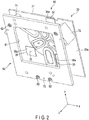
- FIG. 2 is a perspective view showing an assembly 90 formed by assembling a stationary portion 20, a lid member 60, and three pillars 71, 72, and 73 of the shake correction apparatus 100.
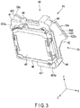
- FIG. 3 is a perspective view showing a movable portion 40 arranged between the stationary portion 20 and the lid member 60 of the assembly 90.
- This shake correction apparatus 100 is an apparatus to be incorporated in, for example, a camera, not shown, to correct a shake caused by a photographer's hands.
- the horizontal axis that passes through the optical axis of a camera and is parallel to an imaging surface 1a of an imaging element 1 (optical element), to be described later, of the shake correction apparatus 100 is referred to as an X-axis.
- the vertical axis that passes through the optical axis is parallel to the imaging surface 1a, is orthogonal to the X-axis, and is referred to as a Y-axis.
- the axis that is orthogonal to the X-axis and the Y-axis, that is, the axis corresponding to the optical axis of the camera is referred to as a Z-axis.
- the front direction in the drawings that extends along the Z-axis is referred to as a front, and the reverse direction is referred to as a rear.
- the stationary portion 20 of the shake correction apparatus 100 includes a rectangular-plate shaped base member 21 to be attached to a camera in a position perpendicular to the optical axis and parallel to the X-Y plane.
- the base member 21 is formed from a magnetic member such as SUS304, for example.
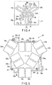
- FIG. 4 is a plane view of the base member 21 as viewed from the front.
- six coils 22S, 22L, 23S, 23L, 24S, and 24L that are arranged in a manner to radiate from a position O (predetermined position) crossing the optical axis, are attached to a front surface 21a of the base member 21.
- the relatively-small three coils 22S, 23S, and 24S are arranged on the inside close to the position O, while the relatively-large three coils 22L, 23L, and 24L are arranged on the outside at some distance from the position O.
- the coils are arranged in a manner wherein the three large coils are shifted mutually by 120 degrees and the three small coils are shifted mutually by 120 degrees.
- the six coils 22S, 22L, 23S, 23L, 24S, and 24L are arranged close to the position O in a manner that the large coils 22L, 23L, and 24L on the outside are partially interposed between the small coils 22S, 23S, and 24S on the inside. Therefore, in each of the coils, the end close to the position O is rounded to be bent in an arc shape. In this manner, an apparatus can be reduced in size by bringing each of the coils 22S, 22L, 23S, 23L, 24S, and 24L as close as possible to the position O.
- the six coils 22S, 22L, 23S, 23L, 24S, and 24L include three coil pairs 22 (22S and 22L), 23 (23S and 23L), and 24 (24S and 24L).
- a distance from the apexes of the arc-shaped ends of the large coils 22L, 23L, 24L to the position O is greater than a distance from the apexes of the arch-shaped ends of the small coils 22S, 23S, and 24S to the position O.
- the winding number of the large coils 22L, 23L, and 24L is made larger than the winding number of the small coils 22S, 23S, and 24S.
- Hall elements 25, 26, and 27 are arranged on the inside of the coils 22S, 23S, and 24S that are smaller (in driving force), respectively.
- the Hall elements 25, 26, and 27 detect a position of the movable portion 40 along the X-Y plane with respect to the stationary portion 20 by detecting magnetic forces from opposed magnets 52a, 52b, 53a, 53b, 54a, and 54b (see FIG. 5 ). At this time, however, there is also an influence of magnetic forces from the coils, and these magnetic forces from the coils interfere with detection of a correct position.
- the Hall elements 25, 26, and 27 are arranged within the small coils 22S, 23S, and 24S that have the smaller winding number and give less influence of magnetic forces than the large coils 22L, 23L, and 24L.
- methods for reducing noise of a detection signal by the Hall elements 25, 26, and 27 include, for example, arranging a Hall element in a coil having therein a relatively-large hollow portion, arranging a Hall element in a position closer to a magnet than to a coil, and arranging a Hall element in a coil that is thinner than the Hall element.
- the front surface 21a of the base member 21 is provided with three concave portions 34, 35, and 36 in a substantially rectangular shape, for housing and arranging therein three balls 31, 32, and 33 (supporting members) to be described later, respectively.
- These three concave portions 34, 35, and 36 are provided in positions different from the six coils 22S, 22L, 23S, 23L, 24S, and 24L described above, and are arranged apart from each other in good balance.
- Ball receiving plates 34a, 35a, and 36a made of, for example, stainless steel for preventing friction of the base member 21, are stuck on the bottom surfaces of the concave portions 34, 35, and 36, which come in slide-contact with the balls 31, 32, and 33.
- the lid member 60 in a rectangular frame shape is arranged in front of the base member 21 with a space therebetween.
- the lid member 60 includes a relatively-large rectangular opening 61 having a size of surrounding a moving range of the movable portion 40.
- this opening 61 is shaped and sized so that the front surface of the movable portion 40 is exposed.
- Each of the pillars 71, 72, and 73 is formed in a square pillar shape.
- Each of the pillars 71, 72, and 73 has one end fastened and secured to the base member 21 by means of a screw, not shown.
- Each of the pillars 71, 72, and 73 has the other end fastened and secured to the lid member 60 by means of screws 62.
- the pillars 71, 72, and 73 have inner surfaces 71a, 72a, and 73a (abutting surfaces) facing to the position O, respectively.
- Mounting angles of the pillars 71, 72, and 73 are set in such a way that a moving range of the movable portion 40 can be regulated by bringing a part of the movable portion 40, to be described later, into the abutting surfaces 71a, 72a, and 73a.
- the movable portion 40 of the shake correction apparatus 100 includes a holder 41 made of, for example, an aluminum die casting, which is relatively lightweight and has some degree of rigidity.
- a plate-shaped yoke 42 made of steel is mounted on the rear of the holder 41.
- the yoke 42 is arranged along the X-Y plane.
- the yoke 42 includes three arm portions 421, 422, and 423 extending outward beyond the outer periphery of the holder 41.
- the arm portions 421, 422, and 423 include distal ends 421a, 422a, and 423a that abut on the abutting surfaces 71a, 72a, and 73a of the pillars 71, 72, and 73 of the stationary portion 20, respectively.
- FIG. 5 is a rear view of the movable portion 40 as viewed along the arrow F5 in FIG. 3 .
- the yoke 42 is fastened and secured to boss portions 44 of the holder 41 by means of screws 43. That is, space S is provided between the holder 41 and the yoke 42.
- FIG. 6 is a side view of the movable portion 40 shown in FIG. 3 as viewed in the direction of the arrow F6.
- a substrate 2 having the imaging element 1 installed in the front surface 2a is arranged in the space S between the holder 41 and the yoke 42.
- the substrate 2 is mounted from the rear of the holder 41 in such a position that the imaging element 1 is arranged in front of the substrate 2. That is, the substrate 2 is mounted on the holder 41 before the yoke 42 is mounted on the holder 41.
- an ultrasonic filter 45 is mounted in front of the holder 41 by means of a filter frame 46.
- the holder 41 includes an opening, not shown, opposed to the imaging surface 1a of the imaging element 1.
- the ultrasonic filter 45 is mounted in a manner to cover this opening from the front. That is, the ultrasonic filter 45 is arranged in front of the imaging element 1 so that the ultrasonic filter 45 and the imaging element 1 are opposed to each other with a space therebetween.
- twelve magnets 52a, 52b, 52c, 52d, 53a, 53b, 53c, 53d, 54a, 54b, 54c, and 54d are glued and secured to a rear surface 42b of the yoke 42 by means of an adhesive, for example.
- These twelve magnets 52a-52d, 53a-53d, and 54a-54d are laid out to be opposed to the coils 22S, 22L, 23S, 23L, 24S, and 24L of the stationary portion 20, respectively. That is, the twelve magnets are arranged in a manner to radiate from the position O.
- a voice coil motor is configured by assigning a pair of two magnets to a single coil. In two magnets assigned to each coil, the magnetic poles opposed to a coil are mutually different. Magnets in each pair are arranged to be opposed to each other along the X-Y plane.
- the movable portion 40 By providing the movable portion 40 with the magnets 52a-52d, 53a-53d, and 54a-54d, the movable portion 40 is attracted to the base member 21 formed from a magnetic member. The three balls 31, 32, and 33 intervene between the movable portion 40 and the base member 21. In this manner, the movable portion 40 is attached to the base member 21 by the action of a magnetic spring due to magnetic forces of the magnets 52a-52d, 53a-53d, and 54a-54d. In this condition, the movable portion 40 can be moved along the X-Y plane. In order to prevent the spring force from becoming too strong at this time, for example, SUS304 is used as a base member. The lid member 60 bears a role in preventing the movable portion 40 from falling when, for example, a high impact is applied to the shake correction apparatus 100.
- FIG. 7 shows a state where the coil pairs 22, 23, and 24 overlap the magnet groups 52 (52a-52d), 53 (53a-53d), and 54(54a-54d).
- the magnets 52a and 52b are assigned to the coil 22S.
- the magnets 52c and 52d are assigned to the coil 22L.
- the magnets 53a and 53b are assigned to the coil 23S.
- the magnets 53c and 53d are assigned to the coil 23L.
- the magnets 54a and 54b are assigned to the coil 24S.
- the magnets 54c and 54d are assigned to the coil 24L.
- the magnets 52b and 53d have the S-pole.
- the magnets 53c and 54a have the N-pole.
- the magnets 54b and 52d have the S-pole.
- the magnets 52c and 53a have the N-pole.
- the magnets 53b and 54d have the S-pole.
- the magnets 54c and 52a have the N-pole.
- the magnets 54c and 52a have the N-pole.
- adjacent magnets do not cancel each other's magnetic flux.
- the effect of strengthening each other's magnetic flux can be expected.
- the rear surface 42b of the yoke 42 is provided with three concave portions 37, 38, and 39 in a substantially rectangular shape, for housing and arranging therein the three balls 31, 32, and 33, respectively. These three concave portions 37, 38, and 39 are opposed to the concave portions 34, 35, and 36 of the base member 21, respectively. Ball receiving plates 37a, 38a, and 39a made of, for example, stainless steel are stuck on the bottom surfaces of the concave portions 37, 38, and 39, which come in slide-contact with the balls 31, 32, and 33.
- FIG. 8 is a block diagram of a control system that controls operation of the shake correction apparatus 100 configured as described above.
- a shake detection portion 111 for detecting camera shake and the three Hall elements 25, 26, and 27 are connected to a control portion 110 (control means) of the shake correction apparatus 100.
- the six coils 22S, 22L, 23S, 23L, 24S, and 24L are also connected to the control portion 110. Energization of the six coils 22S, 22L, 23S, 23L, 24S, and 24L is controlled for each of the pairs of coils opposed to each other across the position O, that is, the coil pairs 22, 23, and 24.
- the control portion 110 feeds a controlling current to each of the coil pairs 22, 23, and 24 based on position information detected by the three Hall elements 25, 26, and 27. In this manner, camera shake is corrected.
- FIGS. 9 to 11 is a driving method of the movable portion 40 at the time of correcting shake.
- the movable portion 40 In order to freely move the movable portion 40 along the X-Y plane, its driving mechanism is required to have three degrees of freedom in, for example, the direction along the X-axis, the direction along the Y-axis, and the direction of rotation.
- the movable portion 40 is made movable in the direction of the X-axis, the direction of the Y-axis, and/or the direction of rotation by forming three pairs of VCMs from the combination of the three coil pairs 22 (22S and 22L), 23 (23S and 23L), and 24 (24S and 24L) and the three magnet groups 52 (52a, 52b, 52c, and 52d), 53 (53a, 53b, 53c, and 53d), and 54 (54a, 54b, 54c, and 54d).
- the coils are each designed in a manner that one coil in each coil pair, i.e., the coils 22L, 23L, and 24L in the coil pairs 22, 23, and 24 have a greater driving force than the other coil, that is, the coils 22S, 23S, and 24S.
- possible approaches include making the two coils have different winding numbers, making the two coils have different sizes, making the two coils have different distances to a magnet, and making the two coils have different distances to the center of gravity of the movable portion 40.
- a difference is given in driving force by making one coil in each pair, i.e., the coils 22L, 23L, and 24L, larger than other coils, i.e., the coils 22S, 23S, and 24S.
- possible approaches for making a difference in driving force include making the magnets opposed to the coils have varied magnetic forces and making the magnets have varied sizes or thicknesses. Possible approaches further include varying the thickness or size of the yoke secured to two coils or corresponding magnets. In this embodiment, the shapes of the coils are varied, while all of the dimensions of the magnets are the same.
- the movable portion 40 If the movable portion 40 is driven by preparing three coil pairs each containing two coils made different in driving force, the movable portion 40 can be moved along the X-Y plane by synthesizing the driving forces of the vector F caused by the coil pairs 22, 23, and 24.
- the same currents may be flowed into the coil pairs 22, 23, and 24 in a manner to exert forces in the same direction as the rotation direction.
- a current of such size and direction that enables the movable portion 40 to be moved in a desired direction may be flowed into each coil pair.
- the direction of currents flowed into all the coils may be reversed.
- feedback control is performed to provide feedback by constantly checking a present position by means of the Hall elements 25, 26, and 27 so that the movable portion 40 is moved in a correct position.
- the coils and the Hall elements are arranged as in the above case, the coils and the Hall elements are not in one-to-one correspondence.
- the three coil pairs 22, 23, and 24 are laid out close to the position O on the stationary portion 20 in a manner to be opposed to the movable portion 40 that holds the imaging element 1 while the magnets 52a-52d, 53a-53d, and 54a-54d are arranged in a manner to overlap the imaging element 1 in the direction of the Z-axis. This achieves downsizing of an apparatus configuration along the X-Y plane.
- the Hall elements 25, 26, and 27 are provided in the smaller coils 22S, 23S, and 24S. This achieves reduction of noise in signals detected by the Hall elements, enables accurate detection of a position, and ensures improved servo performance.
- a member to be driven to correct shake may be an optical element, not an imaging element.
- the coils 22L, 23L, and 24L are protruding to outside.
- an apparatus can be reduced in size by making these coils have different driving forces as shown in FIG. 12 , instead of making them protrude.
- the coils 22L, 23L, and 24L may be made larger in winding number than the coils 22S, 23S, and 24S while the magnets 52c, 52d, 53c, 53d, 54c, and 54d may be greater in thickness than the magnets 52a, 52b, 53a, 53b, 54a, and 54b.
Landscapes
- Physics & Mathematics (AREA)
- Engineering & Computer Science (AREA)
- Multimedia (AREA)
- Signal Processing (AREA)
- General Physics & Mathematics (AREA)
- Optics & Photonics (AREA)
- Adjustment Of Camera Lenses (AREA)
- Studio Devices (AREA)
Abstract
Description
- The present invention relates to a shake correction apparatus for correcting, for example, a camera shake.
- Conventionally, an apparatus in which a movable portion that holds a lens is moved using three driving portions (for example, Patent Literature 1), is, for example, known as a shake correction apparatus for correcting a camera shake. The three driving portions are voice coil motors (VCMs) and are each arranged outside of the effective diameter of a lens.
- Jpn. Pat. Appln. KOKAI Publication No.
2012-108399 - With three driving portions arranged outside of a lens, an apparatus is increased in size along a plane orthogonal to the optical axis, and it becomes difficult to reduce the size of a camera.
- The present invention has been made in consideration of the above, and is intended to provide a shake correction apparatus that enables size reduction.
- According to one aspect of the invention, a shake correction apparatus comprises: a stationary portion on which a plurality of coils are arranged; a movable portion that includes a plurality of magnets arranged to be opposed to the coils, and an optical element or an imaging element; a supporting member for movably supporting the movable portion with respect to the stationary portion along a plane orthogonal to an optical axis of light entering into the optical element or the imaging element; detection means for detecting a position of the movable portion; and control means for controlling a current to be flowed into the coils based on an output of the detection means, wherein the coils include at least three coil pairs when two coils that are arranged to be opposed to each other along the plane orthogonal to the optical axis are paired as one coil pair, and wherein in each of the coil pairs, driving forces of two coils forming each of the coil pairs are different from each other.
- According to another aspect of the invention, the detection means is arranged on an inside of one coil that is smaller in driving force than another coil of the two coils forming each of the at least three coil pairs.
- According to another aspect of the invention, a predetermined position of the stationary portion is located between the two coils forming each of the coil pairs, and the coils are arranged in a manner to radiate from the predetermined position as a center.
- According to another aspect of the invention, in the at least three coil pairs, ends of coils on a side of the predetermined position of the stationary portion are bent in an arc shape, and the ends in the arc shape face each other.
- According to another aspect of the invention, each of the coils is assigned with two opposed magnets, and the two magnets are arranged to face each other along the plane orthogonal to the optical axis.
- According to another aspect of the invention, the shake correction apparatus further comprises a lid member that is attached to the stationary portion and is arranged in such a position that the movable portion is pinched between the lid member and the stationary portion, wherein the stationary portion is formed from a magnetic member, and wherein the movable portion is attached to the stationary portion by magnetic forces of the magnets through the supporting member.
- According to another aspect of the invention, the shake correction apparatus further comprises a plurality of pillars that attach the lid member to the stationary portion outside a moving region of the movable portion, wherein each of the pillars includes an abutting surface that defines the moving region of the movable portion by bring the movable portion in abutment.
- According to another aspect of the invention, the movable portion is provided with the imaging element, and the imaging element is attached to the movable portion in a manner wherein at least a part of the magnets overlaps the imaging element in a direction of an optical axis of light entering into the imaging element.
- According to the present invention, it is possible to provide a shake correction apparatus that enables size reduction.
-
-
FIG. 1 is a perspective view showing a shake correction apparatus according to an embodiment of the present invention. -
FIG. 2 is a perspective view showing an assembly formed by assembling a stationary portion, a lid member, and pillars of the shake correction apparatus shown inFIG. 1 . -
FIG. 3 is a perspective view showing a movable portion arranged between the stationary portion and the lid member shown inFIG. 2 . -
FIG. 4 is a plane view of the stationary portion in the assembly shown inFIG. 2 as viewed from the front. -
FIG. 5 is a rear view of the movable portion shown inFIG. 3 as viewed in the direction denoted by arrow F5. -
FIG. 6 is a side view of the movable portion shown inFIG. 3 as viewed in the direction denoted by arrow F6. -
FIG. 7 is a schematic diagram showing a state where magnets shown inFIG. 5 are stacked on coils shown inFIG. 4 . -
FIG. 8 is a block diagram of a control system that controls operation of the shake correction apparatus shown inFIG. 1 . -
FIG. 9 is a view for illustrating operation of the shake correction apparatus shown inFIG. 1 . -
FIG. 10 is a view for illustrating operation of the shake correction apparatus shown inFIG. 1 . -
FIG. 11 is a view for illustrating operation of the shake correction apparatus shown inFIG. 1 . -
FIG. 12 is a schematic diagram showing substantial parts of a shake correction apparatus according to another embodiment of the present invention. - Embodiments will now be described with reference to the accompanying drawings.
-
FIG. 1 is a perspective view showing ashake correction apparatus 100 according to an embodiment of the present invention.FIG. 2 is a perspective view showing anassembly 90 formed by assembling astationary portion 20, alid member 60, and threepillars shake correction apparatus 100.FIG. 3 is a perspective view showing amovable portion 40 arranged between thestationary portion 20 and thelid member 60 of theassembly 90. Thisshake correction apparatus 100 is an apparatus to be incorporated in, for example, a camera, not shown, to correct a shake caused by a photographer's hands. - In the following description, the horizontal axis that passes through the optical axis of a camera and is parallel to an
imaging surface 1a of an imaging element 1 (optical element), to be described later, of theshake correction apparatus 100, is referred to as an X-axis. The vertical axis that passes through the optical axis is parallel to theimaging surface 1a, is orthogonal to the X-axis, and is referred to as a Y-axis. The axis that is orthogonal to the X-axis and the Y-axis, that is, the axis corresponding to the optical axis of the camera is referred to as a Z-axis. The front direction in the drawings that extends along the Z-axis is referred to as a front, and the reverse direction is referred to as a rear. - As shown in
FIG. 2 , thestationary portion 20 of theshake correction apparatus 100 includes a rectangular-plateshaped base member 21 to be attached to a camera in a position perpendicular to the optical axis and parallel to the X-Y plane. Thebase member 21 is formed from a magnetic member such as SUS304, for example.FIG. 4 is a plane view of thebase member 21 as viewed from the front. As shown inFIGS. 2 and4 , sixcoils front surface 21a of thebase member 21. - Among all the six
coils coils coils - In other words, the six
coils large coils small coils coils - In a different perspective, if two coils of a large coil and a small coil (for example, 22S and 22L) that are opposed to each other across the position O are paired, the six
coils large coils small coils large coils small coils - In the coil pairs 22, 23, and 24,
Hall elements coils Hall elements movable portion 40 along the X-Y plane with respect to thestationary portion 20 by detecting magnetic forces fromopposed magnets FIG. 5 ). At this time, however, there is also an influence of magnetic forces from the coils, and these magnetic forces from the coils interfere with detection of a correct position. In this embodiment, therefore, theHall elements small coils large coils - Other than the above, methods for reducing noise of a detection signal by the
Hall elements - The
front surface 21a of thebase member 21 is provided with threeconcave portions balls concave portions coils Ball receiving plates base member 21, are stuck on the bottom surfaces of theconcave portions balls - The
lid member 60 in a rectangular frame shape is arranged in front of thebase member 21 with a space therebetween. - As shown in
FIGS. 1 and2 , thelid member 60 includes a relatively-largerectangular opening 61 having a size of surrounding a moving range of themovable portion 40. In other words, thisopening 61 is shaped and sized so that the front surface of themovable portion 40 is exposed. - Three
pillars lid member 60 and thebase member 21. Each of thepillars pillars base member 21 by means of a screw, not shown. Each of thepillars lid member 60 by means ofscrews 62. Thepillars pillars movable portion 40 can be regulated by bringing a part of themovable portion 40, to be described later, into the abutting surfaces 71a, 72a, and 73a. - As shown in
FIG. 3 , themovable portion 40 of theshake correction apparatus 100 includes aholder 41 made of, for example, an aluminum die casting, which is relatively lightweight and has some degree of rigidity. A plate-shapedyoke 42 made of steel is mounted on the rear of theholder 41. Theyoke 42 is arranged along the X-Y plane. Theyoke 42 includes threearm portions holder 41. Thearm portions distal ends pillars stationary portion 20, respectively.FIG. 5 is a rear view of themovable portion 40 as viewed along the arrow F5 inFIG. 3 . Theyoke 42 is fastened and secured toboss portions 44 of theholder 41 by means ofscrews 43. That is, space S is provided between theholder 41 and theyoke 42. -
FIG. 6 is a side view of themovable portion 40 shown inFIG. 3 as viewed in the direction of the arrow F6. As shown inFIG. 6 , asubstrate 2 having the imaging element 1 installed in thefront surface 2a is arranged in the space S between theholder 41 and theyoke 42. Thesubstrate 2 is mounted from the rear of theholder 41 in such a position that the imaging element 1 is arranged in front of thesubstrate 2. That is, thesubstrate 2 is mounted on theholder 41 before theyoke 42 is mounted on theholder 41. - On the other hand, an
ultrasonic filter 45 is mounted in front of theholder 41 by means of afilter frame 46. Theholder 41 includes an opening, not shown, opposed to theimaging surface 1a of the imaging element 1. Theultrasonic filter 45 is mounted in a manner to cover this opening from the front. That is, theultrasonic filter 45 is arranged in front of the imaging element 1 so that theultrasonic filter 45 and the imaging element 1 are opposed to each other with a space therebetween. - As shown in
FIG. 5 , twelvemagnets rear surface 42b of theyoke 42 by means of an adhesive, for example. These twelvemagnets 52a-52d, 53a-53d, and 54a-54d are laid out to be opposed to thecoils stationary portion 20, respectively. That is, the twelve magnets are arranged in a manner to radiate from the position O. - The
magnets 52a-52d, 53a-53d, and 54a-54d are arranged in such a position that they at least partially overlap the imaging element 1 in the direction of the Z-axis. This enables size reduction of themovable portion 40 along the X-Y plane and achieves downsizing of an apparatus configuration. In this embodiment, a voice coil motor (VCM) is configured by assigning a pair of two magnets to a single coil. In two magnets assigned to each coil, the magnetic poles opposed to a coil are mutually different. Magnets in each pair are arranged to be opposed to each other along the X-Y plane. - By providing the
movable portion 40 with themagnets 52a-52d, 53a-53d, and 54a-54d, themovable portion 40 is attracted to thebase member 21 formed from a magnetic member. The threeballs movable portion 40 and thebase member 21. In this manner, themovable portion 40 is attached to thebase member 21 by the action of a magnetic spring due to magnetic forces of themagnets 52a-52d, 53a-53d, and 54a-54d. In this condition, themovable portion 40 can be moved along the X-Y plane. In order to prevent the spring force from becoming too strong at this time, for example, SUS304 is used as a base member. Thelid member 60 bears a role in preventing themovable portion 40 from falling when, for example, a high impact is applied to theshake correction apparatus 100. -
FIG. 7 shows a state where the coil pairs 22, 23, and 24 overlap the magnet groups 52 (52a-52d), 53 (53a-53d), and 54(54a-54d). Specifically, themagnets coil 22S. Themagnets coil 22L. Themagnets coil 23S. Themagnets coil 23L. Themagnets coil 24S. Themagnets coil 24L. - Assume that the focus is put on two pairs of magnets (for example, the
magnets magnets FIG. 5 . In this case, all the magnets are configured in a manner that one magnet in one pair and one magnet in the other pair are adjacent to each other and are made to have the same polarities. Specifically, themagnets magnets magnets magnets magnets magnets - In this manner, two magnets (52a and 52b), which are assigned to a single coil (for example, 22S) and have different magnetic poles, are not subjected to the action of reverse magnetic flux from circumferentially-adjacent magnets (54c and 53d), respectively. Thus, adjacent magnets do not cancel each other's magnetic flux. Rather, by setting the same polarities to magnets in circumferentially-adjacent pairs, the effect of strengthening each other's magnetic flux can be expected.
- The
rear surface 42b of theyoke 42 is provided with threeconcave portions balls concave portions concave portions base member 21, respectively.Ball receiving plates concave portions balls -
FIG. 8 is a block diagram of a control system that controls operation of theshake correction apparatus 100 configured as described above. Ashake detection portion 111 for detecting camera shake and the threeHall elements shake correction apparatus 100. The sixcoils control portion 110. Energization of the sixcoils - If shake is detected by means of the
shake detection portion 111 while the camera is used, thecontrol portion 110 feeds a controlling current to each of the coil pairs 22, 23, and 24 based on position information detected by the threeHall elements FIGS. 9 to 11 is a driving method of themovable portion 40 at the time of correcting shake. - In order to freely move the
movable portion 40 along the X-Y plane, its driving mechanism is required to have three degrees of freedom in, for example, the direction along the X-axis, the direction along the Y-axis, and the direction of rotation. In this embodiment, themovable portion 40 is made movable in the direction of the X-axis, the direction of the Y-axis, and/or the direction of rotation by forming three pairs of VCMs from the combination of the three coil pairs 22 (22S and 22L), 23 (23S and 23L), and 24 (24S and 24L) and the three magnet groups 52 (52a, 52b, 52c, and 52d), 53 (53a, 53b, 53c, and 53d), and 54 (54a, 54b, 54c, and 54d). - Therefore, in this embodiment, the coils are each designed in a manner that one coil in each coil pair, i.e., the
coils coils movable portion 40. In this embodiment, a difference is given in driving force by making one coil in each pair, i.e., thecoils coils - Other than the above, possible approaches for making a difference in driving force include making the magnets opposed to the coils have varied magnetic forces and making the magnets have varied sizes or thicknesses. Possible approaches further include varying the thickness or size of the yoke secured to two coils or corresponding magnets. In this embodiment, the shapes of the coils are varied, while all of the dimensions of the magnets are the same.
- In the
shake correction apparatus 100 configured as described above, for example, when the same currents are simultaneously flowed into the twocoils FIG. 9 , a force presented as vector F1 is exerted between thecoil 22S and themagnets coil 22L and themagnets coil 22L is larger than thecoil 22S. Vector F presenting a resultant force of the two vectors F1 and F2 is deviated from the position O to thecoil 22L, thereby causing the driving force in the rotation direction with the position O as the center. - If the
movable portion 40 is driven by preparing three coil pairs each containing two coils made different in driving force, themovable portion 40 can be moved along the X-Y plane by synthesizing the driving forces of the vector F caused by the coil pairs 22, 23, and 24. - For example, in the case of moving the
movable portion 40 in the forward direction (the upper side in the drawings) along the Y-axis, as shown inFIG. 10 , currents are flowed into the twocoils coils movable portion 40. In the case of moving themovable portion 40 in the reverse direction along the Y-axis, the direction of currents flowed into the coil pairs 23 and 24 may be reversed. - In the case of moving the
movable portion 40 in the forward direction (the right side in the drawings) along the X-axis, as shown inFIG. 11 , a current of a predetermined direction and size is flowed into each of the coil pairs 22, 23, and 24 so that a resultant force of three vectors is exerted on themovable portion 40. - In the case of rotating the
movable portion 40, the same currents may be flowed into the coil pairs 22, 23, and 24 in a manner to exert forces in the same direction as the rotation direction. In other words, a current of such size and direction that enables themovable portion 40 to be moved in a desired direction may be flowed into each coil pair. In this case also, if it is desired to move themovable portion 40 in the reverse direction, the direction of currents flowed into all the coils may be reversed. - At this time, feedback control is performed to provide feedback by constantly checking a present position by means of the
Hall elements movable portion 40 is moved in a correct position. In the case where the coils and the Hall elements are arranged as in the above case, the coils and the Hall elements are not in one-to-one correspondence. It is necessary to calculate output results of the threeHall elements movable portion 40, and based on the determined directions and position, to flow a current in a manner that themovable portion 40 is moved again in the predetermined direction along the X-axis, the direction along the Y-axis, and in the rotation position. - As described above, according to this embodiment, the three coil pairs 22, 23, and 24 are laid out close to the position O on the
stationary portion 20 in a manner to be opposed to themovable portion 40 that holds the imaging element 1 while themagnets 52a-52d, 53a-53d, and 54a-54d are arranged in a manner to overlap the imaging element 1 in the direction of the Z-axis. This achieves downsizing of an apparatus configuration along the X-Y plane. - According to this embodiment, among the coil pairs 22, 23, and 24 each including two coils, the
Hall elements smaller coils - The embodiment has been described, but the present invention is in no way limited to this embodiment. Various modifications or applications of the present invention are, of course, possible, without departing from the spirit and scope of the invention. In the embodiment described above, for example, the case of providing the three coil pairs 22, 23, and 24 is described. However, four or more coil pairs may be formed.
- In addition, a member to be driven to correct shake may be an optical element, not an imaging element.
- According to the shape described in the above embodiment, the
coils FIG. 12 , instead of making them protrude. In such a case, thecoils coils magnets magnets
Claims (8)
- A shake correction apparatus comprising:a stationary portion on which a plurality of coils are arranged;a movable portion that includes a plurality of magnets arranged to be opposed to the coils, and an optical element or an imaging element;a supporting member for movably supporting the movable portion with respect to the stationary portion along a plane orthogonal to an optical axis of light entering into the optical element or the imaging element;detection means for detecting a position of the movable portion; andcontrol means for controlling a current to be flowed into the coils based on an output of the detection means,wherein the coils include at least three coil pairs when two coils that are arranged to be opposed to each other along the plane orthogonal to the optical axis are paired as one coil pair, andwherein in each of the coil pairs, driving forces of two coils forming each of the coil pairs are different from each other.
- The shake correction apparatus according to claim 1,
wherein the detection means is arranged on an inside of one coil that is smaller in driving force than another coil of the two coils forming each of the at least three coil pairs. - The shake correction apparatus according to claim 1,
wherein a predetermined position of the stationary portion is located between the two coils forming each of the coil pairs, and
wherein the coils are arranged in a manner to radiate from the predetermined position as a center. - The shake correction apparatus according to claim 3,
wherein in the at least three coil pairs, ends of coils on a side of the predetermined position of the stationary portion are bent in an arc shape, and
wherein the ends in the arc shape face each other. - The shake correction apparatus according to claim 1,
wherein each of the coils is assigned with two opposed magnets, and
wherein the two magnets are arranged to face each other along the plane orthogonal to the optical axis. - The shake correction apparatus according to claim 1, further comprising a lid member that is attached to the stationary portion and is arranged in such a position that the movable portion is pinched between the lid member and the stationary portion,
wherein the stationary portion is formed from a magnetic member, and
wherein the movable portion is attached to the stationary portion by magnetic forces of the magnets through the supporting member. - The shake correction apparatus according to claim 6, further comprising a plurality of pillars that attach the lid member to the stationary portion outside a moving region of the movable portion,
wherein each of the pillars includes an abutting surface that defines the moving region of the movable portion by bring the movable portion in abutment. - The shake correction apparatus according to claim 1,
wherein the movable portion is provided with the imaging element, and
wherein the imaging element is attached to the movable portion in a manner wherein at least a part of the magnets overlaps the imaging element in a direction of an optical axis of light entering into the imaging element.
Applications Claiming Priority (2)
| Application Number | Priority Date | Filing Date | Title |
|---|---|---|---|
| JP2015051126A JP6488161B2 (en) | 2015-03-13 | 2015-03-13 | Blur correction device |
| PCT/JP2015/074123 WO2016147433A1 (en) | 2015-03-13 | 2015-08-26 | Shake correction device |
Publications (3)
| Publication Number | Publication Date |
|---|---|
| EP3270219A1 true EP3270219A1 (en) | 2018-01-17 |
| EP3270219A4 EP3270219A4 (en) | 2018-08-29 |
| EP3270219B1 EP3270219B1 (en) | 2019-06-26 |
Family
ID=56919599
Family Applications (1)
| Application Number | Title | Priority Date | Filing Date |
|---|---|---|---|
| EP15885527.0A Not-in-force EP3270219B1 (en) | 2015-03-13 | 2015-08-26 | Shake correction apparatus |
Country Status (5)
| Country | Link |
|---|---|
| US (1) | US9995988B2 (en) |
| EP (1) | EP3270219B1 (en) |
| JP (1) | JP6488161B2 (en) |
| CN (1) | CN107407850A (en) |
| WO (1) | WO2016147433A1 (en) |
Families Citing this family (7)
| Publication number | Priority date | Publication date | Assignee | Title |
|---|---|---|---|---|
| JP6488161B2 (en) * | 2015-03-13 | 2019-03-20 | オリンパス株式会社 | Blur correction device |
| CN111164506B (en) | 2017-09-27 | 2021-04-23 | 富士胶片株式会社 | Image shake correction device and camera device |
| JP6728122B2 (en) * | 2017-11-20 | 2020-07-22 | 株式会社タムロン | Actuator, lens unit including the same, camera |
| JP6978966B2 (en) * | 2018-03-16 | 2021-12-08 | Omデジタルソリューションズ株式会社 | Image stabilizer |
| CN110278372B (en) * | 2019-06-26 | 2021-03-30 | Oppo广东移动通信有限公司 | Anti-shake method and apparatus, electronic device, computer-readable storage medium |
| US12265279B2 (en) * | 2019-12-30 | 2025-04-01 | Samsung Electro-Mechanics Co., Ltd. | Optical path conversion module, and camera module and portable terminal including the same |
| JP2024122546A (en) | 2023-02-28 | 2024-09-09 | 富士フイルム株式会社 | Image stabilizer and imaging device |
Family Cites Families (13)
| Publication number | Priority date | Publication date | Assignee | Title |
|---|---|---|---|---|
| JP2006171286A (en) * | 2004-12-15 | 2006-06-29 | Pentax Corp | Camera drive mechanism |
| JP4857021B2 (en) * | 2006-05-08 | 2012-01-18 | 株式会社タムロン | Actuator and lens unit and camera provided with the same |
| JP2008170838A (en) * | 2007-01-15 | 2008-07-24 | Casio Comput Co Ltd | Camera shake correction device |
| JP5183098B2 (en) * | 2007-05-28 | 2013-04-17 | キヤノン株式会社 | Image blur correction apparatus, optical apparatus having the same, and imaging apparatus |
| JP5463583B2 (en) * | 2009-07-14 | 2014-04-09 | 株式会社タムロン | Anti-vibration actuator, lens unit and camera equipped with the same |
| KR101085645B1 (en) * | 2010-10-04 | 2011-11-22 | 삼성전기주식회사 | Imaging device with image stabilization |
| JP2012108399A (en) | 2010-11-19 | 2012-06-07 | Tamron Co Ltd | Anti-vibration actuator, and lens unit and camera with the same |
| JP5658071B2 (en) * | 2011-03-31 | 2015-01-21 | 日本電産コパル株式会社 | Image blur correction device |
| JP5884242B2 (en) * | 2012-10-15 | 2016-03-15 | 株式会社タムロン | Actuator, lens unit, and camera |
| KR102079758B1 (en) * | 2012-12-14 | 2020-02-20 | 엘지이노텍 주식회사 | Voice coil motor |
| JP6311434B2 (en) * | 2014-04-25 | 2018-04-18 | ミツミ電機株式会社 | Actuator, camera module, and mobile terminal with camera |
| US9664982B2 (en) * | 2015-03-12 | 2017-05-30 | Panasonic Intellectual Property Management Co., Ltd. | Optical system driving device, lens barrel, and optical device |
| JP6488161B2 (en) * | 2015-03-13 | 2019-03-20 | オリンパス株式会社 | Blur correction device |
-
2015
- 2015-03-13 JP JP2015051126A patent/JP6488161B2/en active Active
- 2015-08-26 CN CN201580077202.9A patent/CN107407850A/en active Pending
- 2015-08-26 WO PCT/JP2015/074123 patent/WO2016147433A1/en not_active Ceased
- 2015-08-26 EP EP15885527.0A patent/EP3270219B1/en not_active Not-in-force
-
2017
- 2017-07-21 US US15/656,715 patent/US9995988B2/en active Active
Also Published As
| Publication number | Publication date |
|---|---|
| WO2016147433A1 (en) | 2016-09-22 |
| EP3270219A4 (en) | 2018-08-29 |
| EP3270219B1 (en) | 2019-06-26 |
| US9995988B2 (en) | 2018-06-12 |
| JP6488161B2 (en) | 2019-03-20 |
| JP2016170339A (en) | 2016-09-23 |
| US20170322475A1 (en) | 2017-11-09 |
| CN107407850A (en) | 2017-11-28 |
Similar Documents
| Publication | Publication Date | Title |
|---|---|---|
| US9995988B2 (en) | Shake correction apparatus | |
| JP5905275B2 (en) | Lens drive device | |
| JP6606257B2 (en) | Optical apparatus and imaging apparatus | |
| JP5463583B2 (en) | Anti-vibration actuator, lens unit and camera equipped with the same | |
| JP5369725B2 (en) | Imaging device | |
| JP5866487B2 (en) | Lens unit and imaging apparatus | |
| US8184167B2 (en) | Optical apparatus having magnet member | |
| JP2008257106A (en) | Blur correction device and optical apparatus | |
| JP2003295249A (en) | Lens barrel and optical equipment using the same | |
| US9703114B2 (en) | Image stabilizer, lens barrel, image pickup apparatus, and optical apparatus | |
| JP2012032543A (en) | Image blur correcting device and imaging device | |
| JP6235450B2 (en) | Image stabilization unit | |
| JP5424413B2 (en) | Anti-vibration actuator, lens unit and camera equipped with the same | |
| JP5817265B2 (en) | Optical device and camera | |
| JP2013228504A (en) | Actuator, lens unit, and camera | |
| JP6074199B2 (en) | Lens barrel and imaging device having the same | |
| JP2008225261A (en) | Lens device | |
| JP2016157031A (en) | Lens driving device | |
| JP2008076646A (en) | Blur correction device and apparatus equipped with the same | |
| US20250138332A1 (en) | Lens barrel and imaging apparatus | |
| JP2010271584A (en) | Optical apparatus having shake correction device | |
| JP2019057820A (en) | Imaging device | |
| JP2016122079A (en) | Lens barrel with shake correction function | |
| JP2016173440A (en) | Lens drive device | |
| JP2016045282A (en) | Lens barrel and imaging device |
Legal Events
| Date | Code | Title | Description |
|---|---|---|---|
| STAA | Information on the status of an ep patent application or granted ep patent |
Free format text: STATUS: THE INTERNATIONAL PUBLICATION HAS BEEN MADE |
|
| PUAI | Public reference made under article 153(3) epc to a published international application that has entered the european phase |
Free format text: ORIGINAL CODE: 0009012 |
|
| STAA | Information on the status of an ep patent application or granted ep patent |
Free format text: STATUS: REQUEST FOR EXAMINATION WAS MADE |
|
| 17P | Request for examination filed |
Effective date: 20170929 |
|
| AK | Designated contracting states |
Kind code of ref document: A1 Designated state(s): AL AT BE BG CH CY CZ DE DK EE ES FI FR GB GR HR HU IE IS IT LI LT LU LV MC MK MT NL NO PL PT RO RS SE SI SK SM TR |
|
| AX | Request for extension of the european patent |
Extension state: BA ME |
|
| DAV | Request for validation of the european patent (deleted) | ||
| DAX | Request for extension of the european patent (deleted) | ||
| A4 | Supplementary search report drawn up and despatched |
Effective date: 20180801 |
|
| RIC1 | Information provided on ipc code assigned before grant |
Ipc: H04N 5/225 20060101ALI20180725BHEP Ipc: H04N 5/232 20060101ALI20180725BHEP Ipc: G03B 5/00 20060101AFI20180725BHEP |
|
| GRAP | Despatch of communication of intention to grant a patent |
Free format text: ORIGINAL CODE: EPIDOSNIGR1 |
|
| STAA | Information on the status of an ep patent application or granted ep patent |
Free format text: STATUS: GRANT OF PATENT IS INTENDED |
|
| RIC1 | Information provided on ipc code assigned before grant |
Ipc: H04N 5/225 20060101ALI20190123BHEP Ipc: H04N 5/232 20060101ALI20190123BHEP Ipc: G03B 5/00 20060101AFI20190123BHEP Ipc: G02B 27/64 20060101ALI20190123BHEP Ipc: G03B 5/02 20060101ALI20190123BHEP |
|
| INTG | Intention to grant announced |
Effective date: 20190212 |
|
| GRAS | Grant fee paid |
Free format text: ORIGINAL CODE: EPIDOSNIGR3 |
|
| GRAA | (expected) grant |
Free format text: ORIGINAL CODE: 0009210 |
|
| STAA | Information on the status of an ep patent application or granted ep patent |
Free format text: STATUS: THE PATENT HAS BEEN GRANTED |
|
| AK | Designated contracting states |
Kind code of ref document: B1 Designated state(s): AL AT BE BG CH CY CZ DE DK EE ES FI FR GB GR HR HU IE IS IT LI LT LU LV MC MK MT NL NO PL PT RO RS SE SI SK SM TR |
|
| REG | Reference to a national code |
Ref country code: GB Ref legal event code: FG4D |
|
| REG | Reference to a national code |
Ref country code: CH Ref legal event code: EP |
|
| REG | Reference to a national code |
Ref country code: AT Ref legal event code: REF Ref document number: 1148987 Country of ref document: AT Kind code of ref document: T Effective date: 20190715 |
|
| REG | Reference to a national code |
Ref country code: DE Ref legal event code: R096 Ref document number: 602015032933 Country of ref document: DE |
|
| REG | Reference to a national code |
Ref country code: IE Ref legal event code: FG4D |
|
| REG | Reference to a national code |
Ref country code: NL Ref legal event code: MP Effective date: 20190626 |
|
| PG25 | Lapsed in a contracting state [announced via postgrant information from national office to epo] |
Ref country code: SE Free format text: LAPSE BECAUSE OF FAILURE TO SUBMIT A TRANSLATION OF THE DESCRIPTION OR TO PAY THE FEE WITHIN THE PRESCRIBED TIME-LIMIT Effective date: 20190626 Ref country code: NO Free format text: LAPSE BECAUSE OF FAILURE TO SUBMIT A TRANSLATION OF THE DESCRIPTION OR TO PAY THE FEE WITHIN THE PRESCRIBED TIME-LIMIT Effective date: 20190926 Ref country code: AL Free format text: LAPSE BECAUSE OF FAILURE TO SUBMIT A TRANSLATION OF THE DESCRIPTION OR TO PAY THE FEE WITHIN THE PRESCRIBED TIME-LIMIT Effective date: 20190626 Ref country code: LT Free format text: LAPSE BECAUSE OF FAILURE TO SUBMIT A TRANSLATION OF THE DESCRIPTION OR TO PAY THE FEE WITHIN THE PRESCRIBED TIME-LIMIT Effective date: 20190626 Ref country code: HR Free format text: LAPSE BECAUSE OF FAILURE TO SUBMIT A TRANSLATION OF THE DESCRIPTION OR TO PAY THE FEE WITHIN THE PRESCRIBED TIME-LIMIT Effective date: 20190626 Ref country code: FI Free format text: LAPSE BECAUSE OF FAILURE TO SUBMIT A TRANSLATION OF THE DESCRIPTION OR TO PAY THE FEE WITHIN THE PRESCRIBED TIME-LIMIT Effective date: 20190626 |
|
| REG | Reference to a national code |
Ref country code: LT Ref legal event code: MG4D |
|
| PG25 | Lapsed in a contracting state [announced via postgrant information from national office to epo] |
Ref country code: LV Free format text: LAPSE BECAUSE OF FAILURE TO SUBMIT A TRANSLATION OF THE DESCRIPTION OR TO PAY THE FEE WITHIN THE PRESCRIBED TIME-LIMIT Effective date: 20190626 Ref country code: RS Free format text: LAPSE BECAUSE OF FAILURE TO SUBMIT A TRANSLATION OF THE DESCRIPTION OR TO PAY THE FEE WITHIN THE PRESCRIBED TIME-LIMIT Effective date: 20190626 Ref country code: BG Free format text: LAPSE BECAUSE OF FAILURE TO SUBMIT A TRANSLATION OF THE DESCRIPTION OR TO PAY THE FEE WITHIN THE PRESCRIBED TIME-LIMIT Effective date: 20190926 Ref country code: GR Free format text: LAPSE BECAUSE OF FAILURE TO SUBMIT A TRANSLATION OF THE DESCRIPTION OR TO PAY THE FEE WITHIN THE PRESCRIBED TIME-LIMIT Effective date: 20190927 |
|
| REG | Reference to a national code |
Ref country code: AT Ref legal event code: MK05 Ref document number: 1148987 Country of ref document: AT Kind code of ref document: T Effective date: 20190626 |
|
| PG25 | Lapsed in a contracting state [announced via postgrant information from national office to epo] |
Ref country code: PT Free format text: LAPSE BECAUSE OF FAILURE TO SUBMIT A TRANSLATION OF THE DESCRIPTION OR TO PAY THE FEE WITHIN THE PRESCRIBED TIME-LIMIT Effective date: 20191028 Ref country code: AT Free format text: LAPSE BECAUSE OF FAILURE TO SUBMIT A TRANSLATION OF THE DESCRIPTION OR TO PAY THE FEE WITHIN THE PRESCRIBED TIME-LIMIT Effective date: 20190626 Ref country code: SK Free format text: LAPSE BECAUSE OF FAILURE TO SUBMIT A TRANSLATION OF THE DESCRIPTION OR TO PAY THE FEE WITHIN THE PRESCRIBED TIME-LIMIT Effective date: 20190626 Ref country code: EE Free format text: LAPSE BECAUSE OF FAILURE TO SUBMIT A TRANSLATION OF THE DESCRIPTION OR TO PAY THE FEE WITHIN THE PRESCRIBED TIME-LIMIT Effective date: 20190626 Ref country code: NL Free format text: LAPSE BECAUSE OF FAILURE TO SUBMIT A TRANSLATION OF THE DESCRIPTION OR TO PAY THE FEE WITHIN THE PRESCRIBED TIME-LIMIT Effective date: 20190626 Ref country code: CZ Free format text: LAPSE BECAUSE OF FAILURE TO SUBMIT A TRANSLATION OF THE DESCRIPTION OR TO PAY THE FEE WITHIN THE PRESCRIBED TIME-LIMIT Effective date: 20190626 Ref country code: RO Free format text: LAPSE BECAUSE OF FAILURE TO SUBMIT A TRANSLATION OF THE DESCRIPTION OR TO PAY THE FEE WITHIN THE PRESCRIBED TIME-LIMIT Effective date: 20190626 |
|
| PG25 | Lapsed in a contracting state [announced via postgrant information from national office to epo] |
Ref country code: ES Free format text: LAPSE BECAUSE OF FAILURE TO SUBMIT A TRANSLATION OF THE DESCRIPTION OR TO PAY THE FEE WITHIN THE PRESCRIBED TIME-LIMIT Effective date: 20190626 Ref country code: SM Free format text: LAPSE BECAUSE OF FAILURE TO SUBMIT A TRANSLATION OF THE DESCRIPTION OR TO PAY THE FEE WITHIN THE PRESCRIBED TIME-LIMIT Effective date: 20190626 Ref country code: IS Free format text: LAPSE BECAUSE OF FAILURE TO SUBMIT A TRANSLATION OF THE DESCRIPTION OR TO PAY THE FEE WITHIN THE PRESCRIBED TIME-LIMIT Effective date: 20191026 Ref country code: IT Free format text: LAPSE BECAUSE OF FAILURE TO SUBMIT A TRANSLATION OF THE DESCRIPTION OR TO PAY THE FEE WITHIN THE PRESCRIBED TIME-LIMIT Effective date: 20190626 |
|
| PG25 | Lapsed in a contracting state [announced via postgrant information from national office to epo] |
Ref country code: TR Free format text: LAPSE BECAUSE OF FAILURE TO SUBMIT A TRANSLATION OF THE DESCRIPTION OR TO PAY THE FEE WITHIN THE PRESCRIBED TIME-LIMIT Effective date: 20190626 |
|
| PG25 | Lapsed in a contracting state [announced via postgrant information from national office to epo] |
Ref country code: PL Free format text: LAPSE BECAUSE OF FAILURE TO SUBMIT A TRANSLATION OF THE DESCRIPTION OR TO PAY THE FEE WITHIN THE PRESCRIBED TIME-LIMIT Effective date: 20190626 Ref country code: DK Free format text: LAPSE BECAUSE OF FAILURE TO SUBMIT A TRANSLATION OF THE DESCRIPTION OR TO PAY THE FEE WITHIN THE PRESCRIBED TIME-LIMIT Effective date: 20190626 |
|
| PG25 | Lapsed in a contracting state [announced via postgrant information from national office to epo] |
Ref country code: IS Free format text: LAPSE BECAUSE OF FAILURE TO SUBMIT A TRANSLATION OF THE DESCRIPTION OR TO PAY THE FEE WITHIN THE PRESCRIBED TIME-LIMIT Effective date: 20200224 Ref country code: LU Free format text: LAPSE BECAUSE OF NON-PAYMENT OF DUE FEES Effective date: 20190826 Ref country code: LI Free format text: LAPSE BECAUSE OF NON-PAYMENT OF DUE FEES Effective date: 20190831 Ref country code: CH Free format text: LAPSE BECAUSE OF NON-PAYMENT OF DUE FEES Effective date: 20190831 Ref country code: MC Free format text: LAPSE BECAUSE OF FAILURE TO SUBMIT A TRANSLATION OF THE DESCRIPTION OR TO PAY THE FEE WITHIN THE PRESCRIBED TIME-LIMIT Effective date: 20190626 |
|
| REG | Reference to a national code |
Ref country code: BE Ref legal event code: MM Effective date: 20190831 |
|
| REG | Reference to a national code |
Ref country code: DE Ref legal event code: R097 Ref document number: 602015032933 Country of ref document: DE |
|
| PLBE | No opposition filed within time limit |
Free format text: ORIGINAL CODE: 0009261 |
|
| STAA | Information on the status of an ep patent application or granted ep patent |
Free format text: STATUS: NO OPPOSITION FILED WITHIN TIME LIMIT |
|
| PG2D | Information on lapse in contracting state deleted |
Ref country code: IS |
|
| PG25 | Lapsed in a contracting state [announced via postgrant information from national office to epo] |
Ref country code: IE Free format text: LAPSE BECAUSE OF NON-PAYMENT OF DUE FEES Effective date: 20190826 |
|
| 26N | No opposition filed |
Effective date: 20200603 |
|
| PG25 | Lapsed in a contracting state [announced via postgrant information from national office to epo] |
Ref country code: SI Free format text: LAPSE BECAUSE OF FAILURE TO SUBMIT A TRANSLATION OF THE DESCRIPTION OR TO PAY THE FEE WITHIN THE PRESCRIBED TIME-LIMIT Effective date: 20190626 Ref country code: BE Free format text: LAPSE BECAUSE OF NON-PAYMENT OF DUE FEES Effective date: 20190831 |
|
| PG25 | Lapsed in a contracting state [announced via postgrant information from national office to epo] |
Ref country code: CY Free format text: LAPSE BECAUSE OF FAILURE TO SUBMIT A TRANSLATION OF THE DESCRIPTION OR TO PAY THE FEE WITHIN THE PRESCRIBED TIME-LIMIT Effective date: 20190626 |
|
| PG25 | Lapsed in a contracting state [announced via postgrant information from national office to epo] |
Ref country code: HU Free format text: LAPSE BECAUSE OF FAILURE TO SUBMIT A TRANSLATION OF THE DESCRIPTION OR TO PAY THE FEE WITHIN THE PRESCRIBED TIME-LIMIT; INVALID AB INITIO Effective date: 20150826 Ref country code: MT Free format text: LAPSE BECAUSE OF FAILURE TO SUBMIT A TRANSLATION OF THE DESCRIPTION OR TO PAY THE FEE WITHIN THE PRESCRIBED TIME-LIMIT Effective date: 20190626 |
|
| REG | Reference to a national code |
Ref country code: DE Ref legal event code: R081 Ref document number: 602015032933 Country of ref document: DE Owner name: OM DIGITAL SOLUTIONS CORPORATION, JP Free format text: FORMER OWNER: OLYMPUS CORPORATION, HACHIOJI-SHI, TOKYO, JP |
|
| REG | Reference to a national code |
Ref country code: GB Ref legal event code: 732E Free format text: REGISTERED BETWEEN 20211202 AND 20211209 |
|
| PG25 | Lapsed in a contracting state [announced via postgrant information from national office to epo] |
Ref country code: MK Free format text: LAPSE BECAUSE OF FAILURE TO SUBMIT A TRANSLATION OF THE DESCRIPTION OR TO PAY THE FEE WITHIN THE PRESCRIBED TIME-LIMIT Effective date: 20190626 |
|
| PGFP | Annual fee paid to national office [announced via postgrant information from national office to epo] |
Ref country code: GB Payment date: 20220822 Year of fee payment: 8 Ref country code: DE Payment date: 20220620 Year of fee payment: 8 |
|
| PGFP | Annual fee paid to national office [announced via postgrant information from national office to epo] |
Ref country code: FR Payment date: 20220823 Year of fee payment: 8 |
|
| REG | Reference to a national code |
Ref country code: DE Ref legal event code: R119 Ref document number: 602015032933 Country of ref document: DE |
|
| GBPC | Gb: european patent ceased through non-payment of renewal fee |
Effective date: 20230826 |
|
| PG25 | Lapsed in a contracting state [announced via postgrant information from national office to epo] |
Ref country code: GB Free format text: LAPSE BECAUSE OF NON-PAYMENT OF DUE FEES Effective date: 20230826 |
|
| PG25 | Lapsed in a contracting state [announced via postgrant information from national office to epo] |
Ref country code: GB Free format text: LAPSE BECAUSE OF NON-PAYMENT OF DUE FEES Effective date: 20230826 Ref country code: FR Free format text: LAPSE BECAUSE OF NON-PAYMENT OF DUE FEES Effective date: 20230831 Ref country code: DE Free format text: LAPSE BECAUSE OF NON-PAYMENT OF DUE FEES Effective date: 20240301 |