EP3270170A1 - Spring contact and socket including spring contact - Google Patents
Spring contact and socket including spring contact Download PDFInfo
- Publication number
- EP3270170A1 EP3270170A1 EP17180484.2A EP17180484A EP3270170A1 EP 3270170 A1 EP3270170 A1 EP 3270170A1 EP 17180484 A EP17180484 A EP 17180484A EP 3270170 A1 EP3270170 A1 EP 3270170A1
- Authority
- EP
- European Patent Office
- Prior art keywords
- exterior body
- spring
- spring contact
- movable portion
- movable
- Prior art date
- Legal status (The legal status is an assumption and is not a legal conclusion. Google has not performed a legal analysis and makes no representation as to the accuracy of the status listed.)
- Withdrawn
Links
- 229910052751 metal Inorganic materials 0.000 claims description 110
- 239000002184 metal Substances 0.000 claims description 110
- 239000000463 material Substances 0.000 claims description 24
- 239000007769 metal material Substances 0.000 claims description 9
- 238000003825 pressing Methods 0.000 abstract description 18
- 238000004519 manufacturing process Methods 0.000 description 29
- 238000000034 method Methods 0.000 description 19
- 238000005452 bending Methods 0.000 description 11
- 239000000523 sample Substances 0.000 description 9
- 229910000679 solder Inorganic materials 0.000 description 9
- 238000012986 modification Methods 0.000 description 6
- 230000004048 modification Effects 0.000 description 6
- RYGMFSIKBFXOCR-UHFFFAOYSA-N Copper Chemical compound [Cu] RYGMFSIKBFXOCR-UHFFFAOYSA-N 0.000 description 4
- 229910052802 copper Inorganic materials 0.000 description 4
- 239000010949 copper Substances 0.000 description 4
- 239000000758 substrate Substances 0.000 description 4
- 238000003466 welding Methods 0.000 description 4
- DMFGNRRURHSENX-UHFFFAOYSA-N beryllium copper Chemical compound [Be].[Cu] DMFGNRRURHSENX-UHFFFAOYSA-N 0.000 description 2
- IUYOGGFTLHZHEG-UHFFFAOYSA-N copper titanium Chemical compound [Ti].[Cu] IUYOGGFTLHZHEG-UHFFFAOYSA-N 0.000 description 2
- 230000007423 decrease Effects 0.000 description 2
- 230000004907 flux Effects 0.000 description 2
- 238000005096 rolling process Methods 0.000 description 2
- 230000006835 compression Effects 0.000 description 1
- 238000007906 compression Methods 0.000 description 1
- 238000005520 cutting process Methods 0.000 description 1
- 230000005611 electricity Effects 0.000 description 1
- PCHJSUWPFVWCPO-UHFFFAOYSA-N gold Chemical compound [Au] PCHJSUWPFVWCPO-UHFFFAOYSA-N 0.000 description 1
- 239000010931 gold Substances 0.000 description 1
- 229910052737 gold Inorganic materials 0.000 description 1
- 238000005304 joining Methods 0.000 description 1
- 150000002739 metals Chemical class 0.000 description 1
- 230000002093 peripheral effect Effects 0.000 description 1
- 238000009751 slip forming Methods 0.000 description 1
- 239000013589 supplement Substances 0.000 description 1
- 238000004804 winding Methods 0.000 description 1
Images









Classifications
-
- H—ELECTRICITY
- H01—ELECTRIC ELEMENTS
- H01R—ELECTRICALLY-CONDUCTIVE CONNECTIONS; STRUCTURAL ASSOCIATIONS OF A PLURALITY OF MUTUALLY-INSULATED ELECTRICAL CONNECTING ELEMENTS; COUPLING DEVICES; CURRENT COLLECTORS
- H01R12/00—Structural associations of a plurality of mutually-insulated electrical connecting elements, specially adapted for printed circuits, e.g. printed circuit boards [PCB], flat or ribbon cables, or like generally planar structures, e.g. terminal strips, terminal blocks; Coupling devices specially adapted for printed circuits, flat or ribbon cables, or like generally planar structures; Terminals specially adapted for contact with, or insertion into, printed circuits, flat or ribbon cables, or like generally planar structures
- H01R12/50—Fixed connections
- H01R12/51—Fixed connections for rigid printed circuits or like structures
- H01R12/55—Fixed connections for rigid printed circuits or like structures characterised by the terminals
- H01R12/58—Fixed connections for rigid printed circuits or like structures characterised by the terminals terminals for insertion into holes
-
- G—PHYSICS
- G01—MEASURING; TESTING
- G01R—MEASURING ELECTRIC VARIABLES; MEASURING MAGNETIC VARIABLES
- G01R1/00—Details of instruments or arrangements of the types included in groups G01R5/00 - G01R13/00 and G01R31/00
- G01R1/02—General constructional details
- G01R1/06—Measuring leads; Measuring probes
- G01R1/067—Measuring probes
- G01R1/06711—Probe needles; Cantilever beams; "Bump" contacts; Replaceable probe pins
- G01R1/06716—Elastic
- G01R1/06722—Spring-loaded
-
- H—ELECTRICITY
- H01—ELECTRIC ELEMENTS
- H01R—ELECTRICALLY-CONDUCTIVE CONNECTIONS; STRUCTURAL ASSOCIATIONS OF A PLURALITY OF MUTUALLY-INSULATED ELECTRICAL CONNECTING ELEMENTS; COUPLING DEVICES; CURRENT COLLECTORS
- H01R13/00—Details of coupling devices of the kinds covered by groups H01R12/70 or H01R24/00 - H01R33/00
- H01R13/02—Contact members
- H01R13/22—Contacts for co-operating by abutting
- H01R13/24—Contacts for co-operating by abutting resilient; resiliently-mounted
- H01R13/2407—Contacts for co-operating by abutting resilient; resiliently-mounted characterized by the resilient means
- H01R13/2421—Contacts for co-operating by abutting resilient; resiliently-mounted characterized by the resilient means using coil springs
-
- H—ELECTRICITY
- H01—ELECTRIC ELEMENTS
- H01R—ELECTRICALLY-CONDUCTIVE CONNECTIONS; STRUCTURAL ASSOCIATIONS OF A PLURALITY OF MUTUALLY-INSULATED ELECTRICAL CONNECTING ELEMENTS; COUPLING DEVICES; CURRENT COLLECTORS
- H01R13/00—Details of coupling devices of the kinds covered by groups H01R12/70 or H01R24/00 - H01R33/00
- H01R13/40—Securing contact members in or to a base or case; Insulating of contact members
- H01R13/405—Securing in non-demountable manner, e.g. moulding, riveting
- H01R13/415—Securing in non-demountable manner, e.g. moulding, riveting by permanent deformation of contact member
-
- H—ELECTRICITY
- H01—ELECTRIC ELEMENTS
- H01R—ELECTRICALLY-CONDUCTIVE CONNECTIONS; STRUCTURAL ASSOCIATIONS OF A PLURALITY OF MUTUALLY-INSULATED ELECTRICAL CONNECTING ELEMENTS; COUPLING DEVICES; CURRENT COLLECTORS
- H01R43/00—Apparatus or processes specially adapted for manufacturing, assembling, maintaining, or repairing of line connectors or current collectors or for joining electric conductors
- H01R43/16—Apparatus or processes specially adapted for manufacturing, assembling, maintaining, or repairing of line connectors or current collectors or for joining electric conductors for manufacturing contact members, e.g. by punching and by bending
Definitions
- the present invention relates to a spring contact including a tubular exterior body, formed from an electrically conductive metal plate, and an interior body, housed in the exterior body, formed from a metal plate, and including a spring portion and a movable portion.
- the present invention also relates to a socket including the spring contact.
- Japanese Unexamined Patent Application Publication Nos. 2011-158454 and 2013-167616 describe inventions relating to a spring contact.
- a contact probe described in Japanese Unexamined Patent Application Publication No. 2011-158454 includes a tubular barrel that houses a coil spring and plungers on both sides of the coil spring. This contact probe is installed in a probe card. When multiple probe pins are interposed between a substrate and a test LSI, the coil spring contracts due to the pressure between the substrate and the test LSI, so that the plungers touch the substrate and the test LSI and conduct electricity to the substrate and the test LSI.
- Japanese Unexamined Patent Application Publication No. 2013-167616 describes a spring-type probe pin formed from an elastic plate material.
- a method for manufacturing this probe pin includes blanking a piece out of a flat plate material and bending the piece.
- an upper sleeve, a lower sleeve, and a buffer operator that is to be housed in both sleeves are integrally formed.
- the upper sleeve and the lower sleeve are assembled together so as to be vertically movable and guidable with respect to each other while housing the buffer operator inside them.
- a probe pin including a spring portion is required to have an electrical path designed so that electric signals do not flow through the spring portion.
- the probe pin described in Japanese Unexamined Patent Application Publication No. 2013-167616 includes the upper sleeve, the lower sleeve, and the buffer operator (coil spring) housed in both sleeves, which are formed from an integrated plate material. Unless the upper sleeve and the lower sleep are brought into reliable contact with each other, electric signals are more likely to flow through the buffer operator. The tubular internal surface of the upper sleeve and the tubular external surface of the lower sleeve simply slide over each other, so that the contact between the upper sleeve and the lower sleeve is unstable and reliable electrical conduction between the sleeves is difficult to obtain.
- the present invention provides a spring contact including a tubular exterior body and a movable portion including a contact portion and having a structure in which the exterior body and the movable portion are reliably electrically connected to each other.
- the present invention also provides a socket including the spring contact.
- the present invention provides a spring contact that includes an exterior body and an interior body housed in the exterior body.
- the interior body includes a spring portion, a movable portion continuous with at least one side of the spring portion, and a contact portion that is part of the movable portion.
- the movable portion is urged by an elastic force of the spring portion in such a direction as to protrude from the exterior body.
- At least one elastic arm is formed integrally with the movable portion and part of the elastic arm is elastically pressed against an internal surface of the exterior body so as to be slidable over the internal surface.
- the present invention also provides a spring contact that includes an exterior body and an interior body housed in the exterior body.
- the interior body includes a spring portion, a movable portion continuous with at least one side of the spring portion, and a contact portion that is part of the movable portion.
- the movable portion is urged by an elastic force of the spring portion in such a direction as to protrude from the exterior body.
- At least one elastic arm is formed integrally with the exterior body and part of the at least one elastic arm is elastically pressed against an external surface of the movable portion.
- At least one elastic arm may be formed integrally with the movable portion and part of the at least one elastic arm may be elastically pressed against an internal surface of the exterior body so as to be slidable over the internal surface.
- elastic arms may be disposed on both of the exterior body and the movable portion.
- the interior body may be formed from a material having a higher modulus of elasticity than a material from which the exterior body is formed.
- the interior body may be formed from a metal material having a higher Young's modulus than a metal material from which the exterior body is formed.
- the interior body and the exterior body may be formed from metal plates and the metal plate from which the interior body or the exterior body is formed and that includes the at least one elastic arm may be thicker than the other metal plate.
- the at least one elastic arm may extend downward in a direction in which the movable body is housed in the exterior body.
- the at least one elastic arm may include a plurality of elastic arms arranged at a plurality of portions around a center line extending in a direction in which the movable body moves.
- the plurality of elastic arms may be arranged at equal angular intervals around the center line.
- the plurality of elastic arms may be arranged at an angle of 180 degrees with a center line along which the movable portion moves interposed therebetween.
- a spring contact according to an aspect may further include fastening portions facing in a second opposing direction, crossing a first opposing direction in which the elastic arms face each other.
- the fastening structure fastens the movable body and the exterior body with each other.
- the contact portion may protrude from a first end portion of the exterior body, a fixing terminal may be integrally formed with a second end portion of the exterior body, and the fixing terminal may include a curved portion.
- the interior body may include the movable portion on each of two sides of the spring portion and the at least one elastic arm may be disposed between each movable portion and the exterior body.
- a socket according to an aspect of the invention includes an insulating casing.
- the casing has a holding space that holds the exterior body of the spring contact according to any of the above-described aspects.
- the exterior body may include a positioning protrusion which is positioned on the casing.
- At least one elastic arm is disposed on either one of both of the movable portion of the interior body and the exterior body and is elastically pressed against the other one of the movable portion and the exterior body. This configuration can enhance the electrical conduction between the movable portion and the exterior body and be more likely to prevent electric signals from flowing through the spring portion.
- the elastic arm can have higher elastic force and extend its life.
- the elastic arm When the elastic arm is disposed on the movable portion so as to extend downward, the elastic arm can be formed in a long form by effectively utilizing the limited length of the movable portion. Thus, the stroke of the movable portion inside the exterior body can be reliably extended.
- a socket 1 illustrated in Fig. 1 includes an insulating casing 2. As illustrated in Fig. 2 , the casing 2 has multiple contact holding spaces 3, in each of which a spring contact 10 according to a first embodiment of the present invention is held.
- the socket 1 is placed on a printed circuit board 4.
- the base portion of each spring contact 10 is exposed from the bottom of the casing 2.
- a fixing terminal 23 disposed at the base portion of the spring contact 10 is fixed to a conductive pattern on the surface of the printed circuit board 4 with a solder joint 5.
- Figs. 2 to 6 illustrate the spring contact 10 according to a first embodiment of the present invention.
- the spring contact 10 includes an assembly of an exterior body 20 and an interior body 30.
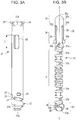
- Fig. 3A is a front view of the exterior body 20 and Fig. 3B is a front view of the interior body 30.
- Fig. 10 and the subsequent drawings illustrate the steps of a method for manufacturing the spring contact 10.
- the exterior body 20 is formed by bending a first metal plate 12 illustrated in Fig. 10 and the interior body 30 is formed by bending a second metal plate 13 illustrated in Fig. 10 .
- Forming the exterior body 20 and the interior body 30 from different metal plates allows the exterior body 20 and the interior body 30 to be formed from metal materials appropriate for their functions.
- the exterior body 20 of the spring contact 10 has a function of allowing electric signals to pass therethrough, so that a material having low electric resistance is selected as the first metal plate 12.
- the interior body 30 includes a spring portion 31, so that a material having a high modulus of elasticity is selected as the second metal plate 13.
- a material having lower electric resistance than a material from which the second metal plate 13 is formed is selected for the first metal plate 12.
- the electric resistance of the first metal plate 12 and the second metal plate 13 is measured per unit plate area while the first metal plate 12 and the second metal plate 13 are in the flat state as illustrated in Fig. 10 .
- a material having a higher modulus of elasticity than the first metal plate 12 is selected as a material for the second metal plate 13.
- the modulus of elasticity is a constant of proportionality of stress/strain per unit plate area obtained when the same bending force is applied to the first metal plate 12 and the second metal plate 13 over the same area.
- the second metal plate 13 is formed from a metal material having a higher Young's modulus than the first metal plate 12 and the first metal plate 12 is formed from a metal material having lower specific resistance than the second metal plate 13.
- a combination of the first metal plate 12 and the second metal plate 13 is selected from various metal materials. Any combination containing copper is preferable.
- the first metal plate 12 and the second metal plate 13 may be formed from the same metal material as long as the electric resistance relationship and the relationship in modulus of elasticity between them can satisfy the above conditions.
- a material having low electric resistance such as a copper plate
- the second metal plate 13 is formed to have a larger plate thickness than the first metal plate 12.
- the second metal plate 13 can have a higher modulus of elasticity and the first metal plate 12 and the second metal plate 13 can have low electric resistance.
- both of the first metal plate 12 and the second metal plate 13 are formed from a material having a high Young's modulus, such as beryllium copper or titanium copper, and the first metal plate 12 is formed to have a larger plate thickness than the second metal plate 13.
- This configuration achieves the spring contact 10 in which the first metal plate 12 has higher electric conductivity, the interior body 30 has a spring portion having a higher elastic force, and the electric resistance is reduced to the lowest possible level.
- Fig. 11 illustrates a first developed structure 20A, blanked out from the first metal plate 12, and a second developed structure 30A, blanked out from the second metal plate 13. Bending the first developed structure 20A forms the exterior body 20 illustrated in Fig. 3A . Bending the second developed structure 30A forms the interior body 30 illustrated in Fig. 3B .
- the interior body 30 includes a spring portion 31, a movable portion 32 continuous with one side of the spring portion 31, and a fixing portion 33 continuous with the other side of the spring portion 31, which are integrated with one another.
- the second developed structure 30A illustrated in Fig. 11 includes a spring-portion development 31A, a movable-portion development 32A, and a fixing-portion development 33A, which are integrated with one another.
- the spring-portion development 31A and a hoop of the first metal plate 12 are connected together with multiple connection ribs 41.
- the movable-portion development 32A and a hoop are connected together with a connection rib 42.
- the fixing-portion development 33A and a hoop are connected together with a connection rib 43.
- the interior body 30 is formed in the following manner.
- a winding center line W1 is determined at a left portion, in Fig. 11 , of the spring-portion development 31A illustrated in Fig. 11 .
- a left end portion 31b of the spring-portion development 31A is deformed so as to roll the winding center line W1 at the near side in Fig. 11 in itself.
- the winding center line W1 is gradually shifted rightward in Fig. 11 .
- the spring portion 31, which is a compressed coil spring having a multiplex winding structure is formed.
- both side edges 32b of the movable-portion development 32A illustrated in Fig. 11 are bent toward the near side in Fig. 11 while having the winding center line W2 at the center, so that the movable portion 32 illustrated in Figs. 3B , 12A , and 12B is formed.
- a lower portion of the movable portion 32 serves as a cylindrical movable body 34 and a tip portion 35 continuous with the movable body 34 tapers so that its diameter gradually decreases toward the upper end.
- the tip portion 35 has a semi-tapered shape having a recess 39 at the far side of Fig. 3B .
- a tip of the tip portion 35 of the movable portion 32 or the portion adjacent the tip serves as a contact portion 35a that touches an external terminal.
- the tip portion 35 has a recess 39.
- the contact portion 35a is thus slightly sharp.
- the contact portion 35a is brought into contact with an external terminal with relatively high pressure.
- the structures of the tip portion 35 and the contact portion 35a are not limited to those according to the above embodiment.
- the tip portion 35 may have a tapered shape without having the recess 39 or a shaper needle shape.
- the tip of the tip portion 35 may have a flat surface, which serves as a contact portion.
- the movable body 34 of the movable portion 32 includes a pair of elastic arms 36, which are integrated together.
- the pair of elastic arms 36 face each other at an angular gap of 180 degrees with the center line O of the interior body 30 interposed therebetween.
- a connection portion 36a between the elastic arms 36 and the movable body 34 is located at an upper portion and an elastically pressing portion 36b is located at a lower free end portion.
- the interior body 30 includes second fasteners 37a and 37b between the spring portion 31 and the movable body 34, that is, between the spring portion 31 and the elastic arms 36.
- the second fastener 37a is formed by bending outward a protruding piece at a lower portion of the movable-portion development 32A illustrated in Fig. 11 .
- the second fastener 37b is formed by cutting and erecting outward a portion at the lower center portion of the movable-portion development 32A illustrated in Fig. 11 .
- a first opposing direction (lateral direction in Fig. 3B ) in which the elastic arms 36 face each other and a second opposing direction (lateral direction in Fig. 5 ) in which the second fasteners 37a and 37b face each other are perpendicular to each other. Since the direction in which the elastic arms 36 face each other and the direction in which the second fasteners 37a and 37b face each other are perpendicular to each other, the space in the movable body 34 of the movable portion 32 can be effectively used to arrange the elastic arms 36 and the second fasteners 37a and 37b, which have different functions.
- both side edges 33b of the fixing-portion development 33A illustrated in Fig. 11 are bent toward the near side in Fig. 11 while having a winding center line W3 at the near side.
- the fixing portion 33 is formed as illustrated in Figs. 3B , 12A , and Fig. 12B .
- the fixing portion 33 has a shape of a cylinder from which a part is recessed.
- First fasteners 38 which protrude outward, are disposed at multiple portions of the fixing portion 33.
- the first fasteners 38 are formed by partially press-forming the fixing-portion development 33A and erecting part of the second metal plate 13 outward.
- the exterior body 20 is formed from the first metal plate 12 into a cylindrical shape.
- the first developed structure 20A illustrated in Fig. 11 is bent so that, in the steps illustrated in Figs. 13 and 14 , the exterior body 20 is formed into a cylinder shape so as to roll the interior body 30, formed by bending the second metal plate 13, in itself.
- the exterior body 20 is formed into a cylinder shape by bending both side edges 20b of the first developed structure 20A toward the near side in Fig. 11 while having the winding center line W4 at the center.
- the joint line between both side edges 20b is located at the far side.
- the exterior body 20 and the interior body 30 may be bent in completely separate steps and the interior body 30 may be inserted into the completed exterior body 20 or a semicylindrical exterior body 20 to be assembled with the exterior body 20.
- the cylindrical exterior body 20 has first fastener receivers 21, open at lower portions (closer to a base end portion), and second fastener receivers 22, open at upper portions (closer to a tip portion).
- the fixing terminal 23 is integrated with a lower portion (base portion) of the exterior body 20.
- the fixing terminal 23 includes a fixed piece 23a, soldered to, for example, a conductive pattern of the board 4 illustrated in Fig. 2 , and a curved portion 23b, extending from the lower portion of the tube of the exterior body 20 to the fixed piece 23a.
- the curved portion 23b is formed into a cylindrical helix so as to follow the external surface of the tube of the exterior body 20.
- the exterior body 20 may be an angular tube.
- the curved portion 23b is formed into a polygonal helix. Nevertheless, the curved portion 23b is preferably formed into a cylindrical helix to avoid local stress concentration on the curved portion 23b.
- the exterior body 20 includes upper positioning protrusions 24, integrated with and bent outward from the upper open end.
- the exterior body 20 also includes lower positioning protrusions 25, integrated with and formed by erecting outward part of the tube of the exterior body 20, at portions slightly above the fixing terminal 23.
- Figs. 4 , 5 , and 6 are sectional views of the structure in which the interior body 30 is housed in the exterior body 20.
- the first fasteners 38 at the lower portion of the interior body 30 are fitted into the first fastener receivers 21 of the exterior body 20 so as to restrict the vertical movement of the fixing portion 33 of the interior body 30 inside the exterior body 20.
- the movable portion 32 of the interior body 30 protrudes upward from the upper open end of the exterior body 20.
- the pair of elastic arms 36 are bent inward so that the elastically pressing portions 36b of the elastic arms 36 are elastically pressed against the tubular internal surface of the exterior body 20.
- the second fasteners 37a and 37b are brought into contact with the tubular internal surface of the exterior body 20, so that the movable portion 32 moves into the exterior body 20 while gradually reducing its diameter.
- the second fasteners 37a and 37b are fastened to the second fastener receivers 22 of the exterior body 20, so that the spring contact 10 is complete.
- the first fasteners 38 and the second fasteners 37a and 37b are fastened to the exterior body 20 while the spring portion (compression coil spring) 31 of the interior body 30 is vertically contracted.
- the interior body 30 is prevented from easily coming off from the exterior body 20.
- the movable portion 32 of the interior body 30 is constantly urged by the elastic restoring force of the spring portion 31 in such a direction as to protrude outward from the upper end opening of the exterior body 20.
- the movable portion 32 can move downward within a range of a vertical opening length L of the second fastener receivers 22 in the exterior body 20.
- the elastically pressing portion 36b of each elastic arm 36 slides over the tubular internal surface of the exterior body 20 while being elastically pressed against the internal surface, so that the movable portion 32 and the exterior body 20 can keep electrical connection with each other.
- the first fasteners 38 formed in the fixing portion 33 of the interior body 30 are fitted into the first fastener receivers 21 of the exterior body 20 when the exterior body 20 and the interior body 30 are to be assembled together.
- part of the fixing portion 33 and the exterior body 20 may be partially fixed together by, for example, laser spot welding.
- the first metal plate 12 and the second metal plate 13 are blanked out from partially surface-joint flat plates and bent.
- a surface-joint portion between the first metal plate 12 and the second metal plate 13 may be left, so that the interior body 30 and the exterior body 20 can keep being partially connected together.
- the first metal plate 12 and the second metal plate 13 are blanked out from an edge-lay clad material, which is a material obtained by joining edge surfaces of plates, and bent.
- an edge-lay clad material which is a material obtained by joining edge surfaces of plates, and bent.
- a junction between the edge surfaces of the first metal plate 12 and the second metal plate 13 may be left, so that the interior body 30 and the exterior body 20 can keep being partially connected together.
- the exterior body 20 of the spring contact 10 is held in any of the contact holding spaces 3 of the insulating casing 2 forming the socket 1.
- the vertical position of the exterior body 20 inside the casing 2 can be fixed by using the upper positioning protrusions 24.
- the exterior body 20 of the spring contact 10 can be inserted with pressure into the contact holding space 3 using the lower positioning protrusions 25.
- the inner peripheral surface of the contact holding spaces 3 is plated with a material such as gold to form a conductive layer so that the conductive layer, used as a ground potential, exerts a shielding function.
- the fixed piece 23a of the fixing terminal 23 is fixed to the conductive pattern on the surface of the board 4 using the solder joint 5.
- the fixing terminal 23 includes a helically curved portion 23b and a fixed piece 23a below the curved portion 23b. This configuration increases the creeping distance from the fixed piece 23a to the lower end of the tube of the exterior body 20. This configuration can render it less likely that the solder joint flux or a molten solder rises from the fixed piece 23a to the internal space of the exterior body 20 using its surface tension. This configuration is thus more likely to prevent the solder joint flux or molten solder from adhering to the spring portion 31 that operates inside the exterior body 20.
- the fixing terminal 23 includes the helically curved portion 23b.
- elastic or plastic deformation of the helically curved portion 23b prevents an excessive release force from being exerted on the solder-joint portion of the fixed piece 23a.
- the fixed piece 23a can be stably fixed with solder.
- the socket 1 holds multiple spring contacts 10.
- the degree of parallelization among the multiple spring contacts 10 thus inevitably varies. If the degree of parallelization varies, any of the spring contacts 10 tilts when the multiple fixed pieces 23a are soldered to the board 4. This tilt allows a large release force to exert on the solder-joint portion of the relevant fixed piece 23a.
- the curved portion 23b is provided, so that the multiple spring contacts 10 can be stably fixed with solder on the surface of the board 4.
- An external terminal of an electronic component such as LSI or an external terminal of a connector is pressed against the contact portion 35a of the movable portion 32 of each spring contact 10.
- the contact portion 35a receives a pressing force
- the spring portion 31 of the interior body 30 contracts and the movable portion 32 is pushed into the exterior body 20 within a range of the opening length L of the second fastener receivers 22 of the exterior body 20.
- each elastic arm 36 of the movable portion 32 slides over the internal surface of the exterior body 20 while being elastically pressed against the internal surface, so that electrical contact resistance between the movable portion 32 and the exterior body 20 decreases and electric signals flow through the path from the movable portion 32 to the fixing terminal 23 via the exterior body 20.
- This configuration hinders electric signals from flowing through the spring portion 31. This configuration can thus reduce the resistance of the spring contact 10, the inductance, and the impedance.
- the interior body 30 is formed from the second metal plate 13 having a high modulus of elasticity and the exterior body 20 is formed from the first metal plate 12 having low resistance.
- the spring portion 31 can keep its spring constant and its stiffness high and the contact portion 35a of the movable portion 32 can keep its contact pressure with an external terminal high.
- the spring portion 31 can have long life against repeated use.
- the exterior body 20 and the fixing terminal 23 located below and integrated with the exterior body 20 have low electric resistance. This configuration achieves a low-resistant current passage.
- the movable body 34 of the movable portion 32 of the interior body 30 includes the elastic arms 36 extending downward.
- the elastic arms 36 can have a long length fully utilizing the vertical length of the movable body 34.
- the elastic arms 36 face each other at an angle of 180 degrees with respect to the center line O of the interior body 30. Even when the movable portion 32 touching an external terminal tilts in any direction (for example, in ⁇ 1 direction) so that the elastic arm 36 on the ⁇ 2 side has lower contact pressure, the elastic arm 36 on the ⁇ 1 side has higher contact pressure.
- the two elastic arms 36 thus supplement each other. The contact resistance between the movable portion 32 and the exterior body 20 is thus prevented from varying.
- the elastic arms 36 are long and extend downward. Thus, even when the pressing force exerted on each movable portion 32 varies among the multiple spring contacts 10 and thus the degree by which the movable portion 32 is pushed into the exterior body 20 varies thereamong, the movable portions 32 can relatively freely tilt regardless of their positions. This tilting can reliably keep each elastically pressing portion 36b in contact with the internal surface of the corresponding exterior body 20.
- the elastic arms 36 may be formed at three or more portions around the movable portion 32. In any case, the elastic arms 36 are preferably arranged at a uniform angle with respect to the center line O.
- Figs. 10 to 15 illustrate steps of a method, according to a first embodiment, for manufacturing the spring contact 10.
- the first metal plate 12 is joined onto part of the second metal plate 13 with their flat surfaces facing each other.
- the reference numeral 12f denotes a hoop that moves the first metal plate 12 to the position at which it overlaps the second metal plate 13.
- connection piece 13a of the second metal plate 13 An upper edge 12a of the first metal plate 12, in Fig. 10 , is superposed on a connection piece 13a of the second metal plate 13.
- the connection piece 13a and the first metal plate 12 are fixed together by laser spot welding or chalking to form a connection portion 15a.
- a lower edge 12b of the first metal plate 12, in Fig. 10 is superposed on a connection piece 13b of the second metal plate 13.
- the connection piece 13b and the first metal plate 12 are fixed together by laser spot welding or chalking to form a connection portion 15b. Except for the overlap width with the first metal plate 12, the second metal plate 13 is absent between the connection piece 13a and the connection piece 13b.
- the first metal plate 12 is subjected to blanking to cut out the first developed structure 20A, forming the exterior body 20, and the second metal plate 13 is subjected to blanking to cut out the second developed structure 30A, forming the interior body 30.
- the first developed structure 20A has an upper portion illustrated in Fig. 11 continuous with a connection rib 44, which is part of the first metal plate 12, and a lower portion illustrated in Fig. 11 continuous with a connection rib 45, which is part of the first metal plate 12.
- the spring-portion development 31A is connected to the multiple connection ribs 41.
- the movable-portion development 32A is connected to the connection rib 42 and the fixing-portion development 33A is connected to the connection rib 43.
- the connection ribs 41, 42, and 43 are part of the second metal plate 13.
- a third step illustrated in Figs. 12A and 12B the second developed structure 30A illustrated in Fig. 11 is bent to form the interior body 30.
- the spring-portion development 31A illustrated in Fig. 11 is rolled to form the spring portion 31.
- the spring-portion development 31A and the connection ribs 41 are cut off along the cutting-plane line C1 in Fig. 11 .
- the movable-portion development 32A illustrated in Fig. 11 is bent to form the movable portion 32 and the fixing-portion development 33A illustrated in Fig. 11 is bent to form the fixing portion 33.
- left and right side portions of the first developed structure 20A are slightly bent to form an exterior body workpiece 20B.
- a lower end portion of the first developed structure 20A is bent to form the fixing terminal 23 having the fixed piece 23a and the helically curved portion 23b.
- a fourth step illustrated in Fig. 13 part of the second metal plate 13 connecting the first developed structure 20A and the second developed structure 30A together is bent and the exterior body workpiece 20B is bent back to be superposed on the bent interior body 30.
- a fifth step illustrated in Fig. 14 the workpiece 20B is further bent into a cylindrical shape so that both side edges 20b are joined together while touching each other. Thus, the cylindrical exterior body 20 is complete.
- the interior body 30 is housed in the exterior body 20.
- the first fasteners 38 of the fixing portion 33 at the lower portions of the interior body 30 enter the first fastener receivers 21 of the exterior body 20, so that the fixing portion 33 of the interior body 30 is held inside the exterior body 20 so as not to move vertically.
- a sixth step illustrated in Fig. 15 the shaped movable portion 32 and the connection rib 42 are detached from each other along the cutting-plane line C2 illustrated in Fig. 11 . Then, the movable portion 32 is pushed into the tube of the exterior body 20 and the second fasteners 37a and 37b of the movable portion 32 are fastened to the second fastener receivers 22 of the exterior body 20.
- the fixing portion 33 of the interior body 30 and the connection rib 43 are detached from each other along the cutting-plane line C3 illustrated in Fig. 11 .
- the first metal plate 12 is cut along the cutting-plane lines C4 and C5 illustrated in Fig. 11 to take out the complete spring contact 10.
- the first developed structure 20A and the second developed structure 30A are blanked out and then bent so that the exterior body 20 and the interior body 30 are assembled together.
- the interior body 30 and the exterior body 20 can be assembled with high accuracy and the operation of assembling the interior body 30 and the exterior body 20 together can be automated.
- the junction between the flat surfaces of the first metal plate 12 and the second metal plate 13 may be left instead of providing the fastening structure including the first fastener receivers 21 and the first fasteners 38 illustrated in Fig. 4 . Leaving the junction can keep the interior body 30 and the exterior body 20 being partially connected together.
- Figs. 16 to 19 illustrate steps of a method according to a second embodiment for manufacturing the spring contact 10.
- first developed structures 20A are blanked out from the second metal plate 13, as illustrated in Fig. 16A
- second developed structures 30A are blanked out from the first metal plate 12, as illustrated in Fig. 16B .
- Each first developed structure 20A and each second developed structure 30A have the same shapes as those illustrated in Fig. 11 .
- a second step as illustrated in Fig. 17A , the second developed structure 30A of the second metal plate 13 is bent to form the interior body 30.
- both side portions of the first developed structure 20A of the first metal plate 12 are processed to form the exterior body workpiece 20B.
- the fixing terminal 23 of the exterior body 20 is bent.
- the shape of the workpiece 20B is the same as that illustrated in Figs. 12A and 12B .
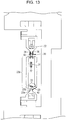
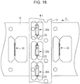
- a third step illustrated in Fig. 18 the first metal plate 12 illustrated in Fig. 17B is turned over and superposed on the second metal plate 13 and the exterior body workpiece 20B is superposed on the interior body 30.
- a fourth step illustrated in Fig. 19 the workpiece 20B is bent into a cylinder shape so as to wrap the interior body 30 to form the exterior body 20.
- the second metal plate 13 is transmitted section by section in the X direction and the first metal plate 12 is transmitted section by section in the Y direction so that the interior body 30 and the workpiece 20B are sequentially assembled together.
- the first metal plate 12 is superposed on the second metal plate 13.
- the first metal plate 12 and the second metal plate 13 are disposed so as to partially face each other, partially joined together by welding or chalking, and then shifted to blanking and bending operations.
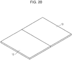
- an edge-lay clad material illustrated in Fig. 20 is used.
- An edge-lay clad material is a metal plate in which the first metal plate 12 and the second metal plate 13 made from different metals are joined together at their edge surfaces. From this edge-lay clad material, the first developed structure 20A and the second developed structure 30A are blanked out, as illustrated in Fig. 11 , and then bent into the exterior body 20 and the interior body 30. At this time, instead of providing the fastening structure including the first fastener receivers 21 and the first fasteners 38 illustrated in Fig. 4 , a junction between the edge surfaces of the first metal plate 12 and the second metal plate 13 may be left so that the interior body 30 and the exterior body 20 can be kept being partially connected together.
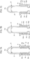
- Figs. 7A to 7C illustrate modifications of the spring contact 10 according to the first embodiment.
- the movable body 34 of the movable portion 32 of the interior body 30 includes elastic arms 36 extending upward.
- Each elastic arm 36 has a connection portion 36a at a lower portion and an elastically pressing portion 36b at an upper portion.
- the exterior body 20 includes elastic arms 136.
- Each elastic arm 136 extends upward and has a connection portion 136a at a lower portion and an elastically pressing portion 136b at an upper portion.
- the exterior body 20 includes elastic arms 136 extending downward.
- Each elastic arm 136 has a connection portion 136a at an upper portion and an elastically pressing portion 136b at a lower portion.
- the elastically pressing portion 136b is elastically pressed against the external surface of the movable body 34 of the movable portion 32.
- the elastic arms 36 or 136 may have any form.
- the elastic arms are included in the interior body 30 since the interior body 30 has a structure having a higher modulus of elasticity than the exterior body 20.
- the movable portion When the elastic arms are to be disposed on the movable portion, the movable portion may have a larger thickness than the exterior body. When the elastic arms are to be disposed on the exterior body, the exterior body may have a larger thickness than the elastic arms.
- the elastic arms 36 extend in the movement direction of the movable portions 32 and the elastically pressing portions 36b protrude downward, as illustrated in the first embodiment illustrated in Fig. 6 .
- the interior body 30 and the exterior body 20 may be integrally and continuously formed from the same metal plate.
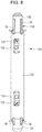
- Fig. 8 illustrates a spring contact 101 according to a second embodiment of the present invention.
- Fig. 9A illustrates an exterior body 120 and
- Fig. 9B illustrates an interior body 130.
- the exterior body 120 is formed from the first metal plate 12 and the interior body 130 is formed from the second metal plate 13.
- the interior body 130 includes a spring portion 131, a first movable portion 132, continuous with one side of the spring portion 131, and a second movable portion 133, continuous with the other side of the spring portion 131.
- the first movable portion 132 includes elastic arms 36 and a fastener 137.
- the second movable portion 133 includes elastic arms 36 and a fastener 138.
- the first metal plate 12 and the second metal plate 13 are bent to form the exterior body 120 and the interior body 130 and the exterior body 120 and the interior body 130 are assembled together.
- the fastener 137 of the first movable portion 132 is fastened to a fastener receiver 122 of the exterior body 120 and the fastener 138 of the second movable portion 133 is fastened to a fastener receiver 123 of the exterior body 120.
- the spring portion 131 contracts.
- the first movable portion 132 and the second movable portion 133 are urged so as to vertically protrude from the exterior body 120.
- the elastically pressing portion 36b of each elastic arm 36 of the first movable portion 132 and the elastically pressing portion 36b of each elastic arm 36 of the second movable portion 133 are elastically pressed against the internal surface of the exterior body 120.
- the first movable portion 132 and the second movable portion 133 are electrically connected to each other through the exterior body 120.
- the first movable portion 132 and the second movable portion 133 protrude from both end openings of the exterior body 120.
- the contact portion of the first movable portion 132 and the contact portion of the second movable portion 133 are elastically pressed against the conductive pattern of the board or an external terminal.
Landscapes
- Physics & Mathematics (AREA)
- General Physics & Mathematics (AREA)
- Engineering & Computer Science (AREA)
- Manufacturing & Machinery (AREA)
- Measuring Leads Or Probes (AREA)
- Details Of Connecting Devices For Male And Female Coupling (AREA)
- Testing Or Measuring Of Semiconductors Or The Like (AREA)
- Connecting Device With Holders (AREA)
Abstract
An interior body (30) is housed in a tubular exterior body (20). The interior body (30) includes a spring portion (31), a movable portion (32), and a fixing portion (33), which are integrated together. Elastic arms (36) are disposed on the movable portion (32) so as to extend downward. Each elastic arm (36) includes, at a lower end portion, an elastically pressing portion (36b), which is elastically pressed against a tubular internal surface of the exterior body (20). Since the elastically pressing portion (36b) is elastically pressed against the exterior body (20), electric signals are more likely to flow between the movable portion (32) and the exterior body (20) and more likely to be prevented from leaking to the spring portion (31).
Description
- The present invention relates to a spring contact including a tubular exterior body, formed from an electrically conductive metal plate, and an interior body, housed in the exterior body, formed from a metal plate, and including a spring portion and a movable portion. The present invention also relates to a socket including the spring contact.
- Japanese Unexamined Patent Application Publication Nos.
2011-158454 2013-167616 - A contact probe described in Japanese Unexamined Patent Application Publication No.
2011-158454 - Japanese Unexamined Patent Application Publication No.
2013-167616 - A probe pin including a spring portion is required to have an electrical path designed so that electric signals do not flow through the spring portion.
- Preventing electric signals from flowing through the coil spring in the contact probe described in Japanese Unexamined Patent Application Publication No.
2011-158454 - The probe pin described in Japanese Unexamined Patent Application Publication No.
2013-167616 - The present invention provides a spring contact including a tubular exterior body and a movable portion including a contact portion and having a structure in which the exterior body and the movable portion are reliably electrically connected to each other. The present invention also provides a socket including the spring contact.
- The present invention provides a spring contact that includes an exterior body and an interior body housed in the exterior body. The interior body includes a spring portion, a movable portion continuous with at least one side of the spring portion, and a contact portion that is part of the movable portion. The movable portion is urged by an elastic force of the spring portion in such a direction as to protrude from the exterior body. At least one elastic arm is formed integrally with the movable portion and part of the elastic arm is elastically pressed against an internal surface of the exterior body so as to be slidable over the internal surface.
- The present invention also provides a spring contact that includes an exterior body and an interior body housed in the exterior body. The interior body includes a spring portion, a movable portion continuous with at least one side of the spring portion, and a contact portion that is part of the movable portion. The movable portion is urged by an elastic force of the spring portion in such a direction as to protrude from the exterior body. At least one elastic arm is formed integrally with the exterior body and part of the at least one elastic arm is elastically pressed against an external surface of the movable portion.
- In a spring contact according to an aspect, at least one elastic arm may be formed integrally with the movable portion and part of the at least one elastic arm may be elastically pressed against an internal surface of the exterior body so as to be slidable over the internal surface. Specifically, elastic arms may be disposed on both of the exterior body and the movable portion.
- In a spring contact according to an aspect, the interior body may be formed from a material having a higher modulus of elasticity than a material from which the exterior body is formed.
- In a spring contact according to an aspect, for example, the interior body may be formed from a metal material having a higher Young's modulus than a metal material from which the exterior body is formed.
- In a spring contact according to an aspect, the interior body and the exterior body may be formed from metal plates and the metal plate from which the interior body or the exterior body is formed and that includes the at least one elastic arm may be thicker than the other metal plate.
- In a spring contact according to an aspect, the at least one elastic arm may extend downward in a direction in which the movable body is housed in the exterior body.
- In a spring contact according to an aspect, the at least one elastic arm may include a plurality of elastic arms arranged at a plurality of portions around a center line extending in a direction in which the movable body moves.
- In a spring contact according to an aspect, the plurality of elastic arms may be arranged at equal angular intervals around the center line.
- In a spring contact according to an aspect, the plurality of elastic arms may be arranged at an angle of 180 degrees with a center line along which the movable portion moves interposed therebetween.
- A spring contact according to an aspect may further include fastening portions facing in a second opposing direction, crossing a first opposing direction in which the elastic arms face each other. The fastening structure fastens the movable body and the exterior body with each other.
- In a spring contact according to an aspect, the contact portion may protrude from a first end portion of the exterior body, a fixing terminal may be integrally formed with a second end portion of the exterior body, and the fixing terminal may include a curved portion.
- In a spring contact according to an aspect, the interior body may include the movable portion on each of two sides of the spring portion and the at least one elastic arm may be disposed between each movable portion and the exterior body.
- A socket according to an aspect of the invention includes an insulating casing. The casing has a holding space that holds the exterior body of the spring contact according to any of the above-described aspects.
- In the spring contact according to an aspect, the exterior body may include a positioning protrusion which is positioned on the casing.
- In an aspect of the present invention, at least one elastic arm is disposed on either one of both of the movable portion of the interior body and the exterior body and is elastically pressed against the other one of the movable portion and the exterior body. This configuration can enhance the electrical conduction between the movable portion and the exterior body and be more likely to prevent electric signals from flowing through the spring portion.
- Particularly, when the interior body including the spring portion and the movable portion is formed from a material having a higher modulus of elasticity than a material from which the exterior body is formed and the elastic arm is disposed on the movable portion, the elastic arm can have higher elastic force and extend its life.
- When the elastic arm is disposed on the movable portion so as to extend downward, the elastic arm can be formed in a long form by effectively utilizing the limited length of the movable portion. Thus, the stroke of the movable portion inside the exterior body can be reliably extended.
-
-
Fig. 1 is a perspective view of a socket according to an embodiment including multiple spring contacts; -
Fig. 2 is a front view of a section of the socket illustrated inFig. 1 and the exterior of a spring contact according to a first embodiment of the present invention; -
Fig. 3A is a front view of an exterior body of the spring contact illustrated inFig. 2 ; -
Fig. 3B is a front view of an interior body of the spring contact illustrated inFig. 2 ; -
Fig. 4 is a sectional view of the spring contact illustrated inFig. 2 taken vertically and viewed from the front; -
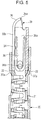
Fig. 5 is a partially enlarged sectional view of the spring contact illustrated inFig. 2 taken along the line V-V; -
Fig. 6 is a partially enlarged sectional view of the vertical section illustrated inFig. 4 ; -
Figs. 7A, 7B, and 7C are partially enlarged sectional views of a portion at which elastic arms according to modifications are disposed; -
Fig. 8 is a front view of the exterior of a spring contact according to a second embodiment of the present invention; -
Fig. 9A is a front view of an exterior body of the spring contact illustrated inFig. 8 ; -
Fig. 9B is a front view of an interior body of the spring contact illustrated inFig. 8 ; -
Fig. 10 illustrates a first step of a method according to a first embodiment for manufacturing the spring contact illustrated inFig. 2 ; -
Fig. 11 illustrates a second step of the method according to the first embodiment for manufacturing the spring contact illustrated inFig. 2 ; -
Fig. 12A illustrates a third step of the method according to the first embodiment for manufacturing the spring contact illustrated inFig. 2 ; -
Fig. 12B is a perspective view of the third step illustrated inFig. 12A ; -
Fig. 13 illustrates a fourth step of the method according to the first embodiment for manufacturing the spring contact illustrated inFig. 2 ; -
Fig. 14 illustrates a fifth step of the method according to the first embodiment for manufacturing the spring contact illustrated inFig. 2 ; -
Fig. 15 illustrates a sixth step of the method according to the first embodiment for manufacturing the spring contact illustrated inFig. 2 ; -
Figs. 16A and 16B illustrate a first step of a method according to a second embodiment for manufacturing the spring contact illustrated inFig. 2 ; -
Figs. 17A and 17B illustrate a second step of the method according to the second embodiment for manufacturing the spring contact illustrated inFig. 2 ; -
Fig. 18 illustrates a third step of the method according to the second embodiment for manufacturing the spring contact illustrated inFig. 2 ; -
Fig. 19 illustrates a fourth step of the method according to the second embodiment for manufacturing the spring contact illustrated inFig. 2 ; and -
Fig. 20 is a perspective view of an edge-lay clad material used in a method according to a third embodiment for manufacturing the spring contact illustrated inFig. 2 . - A
socket 1 illustrated inFig. 1 includes an insulatingcasing 2. As illustrated inFig. 2 , thecasing 2 has multiplecontact holding spaces 3, in each of which aspring contact 10 according to a first embodiment of the present invention is held. - As illustrated in
Fig. 2 , thesocket 1 is placed on a printedcircuit board 4. The base portion of eachspring contact 10 is exposed from the bottom of thecasing 2. A fixingterminal 23 disposed at the base portion of thespring contact 10 is fixed to a conductive pattern on the surface of the printedcircuit board 4 with asolder joint 5. -
Figs. 2 to 6 illustrate thespring contact 10 according to a first embodiment of the present invention. - The
spring contact 10 includes an assembly of anexterior body 20 and aninterior body 30.Fig. 3A is a front view of theexterior body 20 andFig. 3B is a front view of theinterior body 30. -
Fig. 10 and the subsequent drawings illustrate the steps of a method for manufacturing thespring contact 10. Theexterior body 20 is formed by bending afirst metal plate 12 illustrated inFig. 10 and theinterior body 30 is formed by bending asecond metal plate 13 illustrated inFig. 10 . Forming theexterior body 20 and theinterior body 30 from different metal plates allows theexterior body 20 and theinterior body 30 to be formed from metal materials appropriate for their functions. - The
exterior body 20 of thespring contact 10 has a function of allowing electric signals to pass therethrough, so that a material having low electric resistance is selected as thefirst metal plate 12. Theinterior body 30 includes aspring portion 31, so that a material having a high modulus of elasticity is selected as thesecond metal plate 13. - For example, a material having lower electric resistance than a material from which the
second metal plate 13 is formed is selected for thefirst metal plate 12. The electric resistance of thefirst metal plate 12 and thesecond metal plate 13 is measured per unit plate area while thefirst metal plate 12 and thesecond metal plate 13 are in the flat state as illustrated inFig. 10 . On the other hand, a material having a higher modulus of elasticity than thefirst metal plate 12 is selected as a material for thesecond metal plate 13. Here, the modulus of elasticity is a constant of proportionality of stress/strain per unit plate area obtained when the same bending force is applied to thefirst metal plate 12 and thesecond metal plate 13 over the same area. - In this embodiment, the
second metal plate 13 is formed from a metal material having a higher Young's modulus than thefirst metal plate 12 and thefirst metal plate 12 is formed from a metal material having lower specific resistance than thesecond metal plate 13. - An example of the above combination is beryllium copper or titanium copper for the
second metal plate 13 and copper with high purity, called tough pitch copper, for thefirst metal plate 12. A combination of thefirst metal plate 12 and thesecond metal plate 13 is selected from various metal materials. Any combination containing copper is preferable. - The
first metal plate 12 and thesecond metal plate 13 may be formed from the same metal material as long as the electric resistance relationship and the relationship in modulus of elasticity between them can satisfy the above conditions. For example, when thespring contact 10 having extremely low electric resistance is to be formed, a material having low electric resistance, such as a copper plate, is used. Here, thesecond metal plate 13 is formed to have a larger plate thickness than thefirst metal plate 12. Thus, thesecond metal plate 13 can have a higher modulus of elasticity and thefirst metal plate 12 and thesecond metal plate 13 can have low electric resistance. - When the
spring contact 10 having long life against repeated use regardless of whether the electric resistance is high or low is to be formed, both of thefirst metal plate 12 and thesecond metal plate 13 are formed from a material having a high Young's modulus, such as beryllium copper or titanium copper, and thefirst metal plate 12 is formed to have a larger plate thickness than thesecond metal plate 13. This configuration achieves thespring contact 10 in which thefirst metal plate 12 has higher electric conductivity, theinterior body 30 has a spring portion having a higher elastic force, and the electric resistance is reduced to the lowest possible level. - In the manufacturing step illustrated in
Fig. 10 , thefirst metal plate 12 and thesecond metal plate 13 are subjected to blanking during a pressing step in the state where thefirst metal plate 12 and thesecond metal plate 13 are joined together.Fig. 11 illustrates a firstdeveloped structure 20A, blanked out from thefirst metal plate 12, and a seconddeveloped structure 30A, blanked out from thesecond metal plate 13. Bending the firstdeveloped structure 20A forms theexterior body 20 illustrated inFig. 3A . Bending the seconddeveloped structure 30A forms theinterior body 30 illustrated inFig. 3B . - As illustrated in
Fig. 3B , theinterior body 30 includes aspring portion 31, amovable portion 32 continuous with one side of thespring portion 31, and a fixingportion 33 continuous with the other side of thespring portion 31, which are integrated with one another. The seconddeveloped structure 30A illustrated inFig. 11 includes a spring-portion development 31A, a movable-portion development 32A, and a fixing-portion development 33A, which are integrated with one another. The spring-portion development 31A and a hoop of thefirst metal plate 12 are connected together withmultiple connection ribs 41. The movable-portion development 32A and a hoop are connected together with aconnection rib 42. The fixing-portion development 33A and a hoop are connected together with aconnection rib 43. - The
interior body 30 is formed in the following manner. A winding center line W1 is determined at a left portion, inFig. 11 , of the spring-portion development 31A illustrated inFig. 11 . Aleft end portion 31b of the spring-portion development 31A is deformed so as to roll the winding center line W1 at the near side inFig. 11 in itself. While being rolled in the spring-portion development 31A, the winding center line W1 is gradually shifted rightward inFig. 11 . Thus, as illustrated inFigs. 3B ,12A , and12B , thespring portion 31, which is a compressed coil spring having a multiplex winding structure, is formed. - In addition, both side edges 32b of the movable-
portion development 32A illustrated inFig. 11 are bent toward the near side inFig. 11 while having the winding center line W2 at the center, so that themovable portion 32 illustrated inFigs. 3B ,12A , and12B is formed. A lower portion of themovable portion 32 serves as a cylindricalmovable body 34 and atip portion 35 continuous with themovable body 34 tapers so that its diameter gradually decreases toward the upper end. As illustrated inFig. 5 , thetip portion 35 has a semi-tapered shape having arecess 39 at the far side ofFig. 3B . In themovable portion 32, a tip of thetip portion 35 of themovable portion 32 or the portion adjacent the tip serves as acontact portion 35a that touches an external terminal. - As illustrated in
Fig. 5 , thetip portion 35 has arecess 39. Thecontact portion 35a is thus slightly sharp. When receiving the elastic force of thespring portion 31, thecontact portion 35a is brought into contact with an external terminal with relatively high pressure. The structures of thetip portion 35 and thecontact portion 35a are not limited to those according to the above embodiment. Thetip portion 35 may have a tapered shape without having therecess 39 or a shaper needle shape. Alternatively, the tip of thetip portion 35 may have a flat surface, which serves as a contact portion. - As illustrated in
Fig. 6 in an enlarged manner, themovable body 34 of themovable portion 32 includes a pair ofelastic arms 36, which are integrated together. The pair ofelastic arms 36 face each other at an angular gap of 180 degrees with the center line O of theinterior body 30 interposed therebetween. Aconnection portion 36a between theelastic arms 36 and themovable body 34 is located at an upper portion and an elasticallypressing portion 36b is located at a lower free end portion. As illustrated inFigs. 11 ,12A , and12B , while themovable portion 32 is being formed by bending the movable-portion development 32A, thesecond metal plate 13 forming theelastic arms 36 is subjected to blanking and the elastically pressingportion 36b is formed with pressure so as to protrude outward from the lower end of eachelastic arm 36. - As illustrated in
Figs. 3A and5 , theinterior body 30 includessecond fasteners spring portion 31 and themovable body 34, that is, between thespring portion 31 and theelastic arms 36. Thesecond fastener 37a is formed by bending outward a protruding piece at a lower portion of the movable-portion development 32A illustrated inFig. 11 . Thesecond fastener 37b is formed by cutting and erecting outward a portion at the lower center portion of the movable-portion development 32A illustrated inFig. 11 . - In the
movable portion 32 of theinterior body 30, a first opposing direction (lateral direction inFig. 3B ) in which theelastic arms 36 face each other and a second opposing direction (lateral direction inFig. 5 ) in which thesecond fasteners elastic arms 36 face each other and the direction in which thesecond fasteners movable body 34 of themovable portion 32 can be effectively used to arrange theelastic arms 36 and thesecond fasteners - Subsequently, both side edges 33b of the fixing-
portion development 33A illustrated inFig. 11 are bent toward the near side inFig. 11 while having a winding center line W3 at the near side. Thus, the fixingportion 33 is formed as illustrated inFigs. 3B ,12A , andFig. 12B . The fixingportion 33 has a shape of a cylinder from which a part is recessed.First fasteners 38, which protrude outward, are disposed at multiple portions of the fixingportion 33. In the steps illustrated inFigs. 11 ,12A , and12B , thefirst fasteners 38 are formed by partially press-forming the fixing-portion development 33A and erecting part of thesecond metal plate 13 outward. - As illustrated in
Figs. 2 and3A , theexterior body 20 is formed from thefirst metal plate 12 into a cylindrical shape. In the manufacturing method illustrated inFig. 10 and the subsequent drawings, the firstdeveloped structure 20A illustrated inFig. 11 is bent so that, in the steps illustrated inFigs. 13 and14 , theexterior body 20 is formed into a cylinder shape so as to roll theinterior body 30, formed by bending thesecond metal plate 13, in itself. In the manufacturing method illustrated inFig. 11 and the subsequent drawings, theexterior body 20 is formed into a cylinder shape by bending both side edges 20b of the firstdeveloped structure 20A toward the near side inFig. 11 while having the winding center line W4 at the center. InFig. 3A , the joint line between bothside edges 20b is located at the far side. - As another example of the method for manufacturing the
spring contact 10 according to the present invention, theexterior body 20 and theinterior body 30 may be bent in completely separate steps and theinterior body 30 may be inserted into the completedexterior body 20 or a semicylindricalexterior body 20 to be assembled with theexterior body 20. - As illustrated in
Fig. 3A , the cylindricalexterior body 20 hasfirst fastener receivers 21, open at lower portions (closer to a base end portion), andsecond fastener receivers 22, open at upper portions (closer to a tip portion). - As illustrated in
Fig. 3A , the fixingterminal 23 is integrated with a lower portion (base portion) of theexterior body 20. The fixingterminal 23 includes a fixedpiece 23a, soldered to, for example, a conductive pattern of theboard 4 illustrated inFig. 2 , and acurved portion 23b, extending from the lower portion of the tube of theexterior body 20 to the fixedpiece 23a. Thecurved portion 23b is formed into a cylindrical helix so as to follow the external surface of the tube of theexterior body 20. Theexterior body 20 may be an angular tube. In this case, thecurved portion 23b is formed into a polygonal helix. Nevertheless, thecurved portion 23b is preferably formed into a cylindrical helix to avoid local stress concentration on thecurved portion 23b. - As illustrated in
Fig. 3A , theexterior body 20 includesupper positioning protrusions 24, integrated with and bent outward from the upper open end. Theexterior body 20 also includeslower positioning protrusions 25, integrated with and formed by erecting outward part of the tube of theexterior body 20, at portions slightly above the fixingterminal 23. -
Figs. 4 ,5 , and6 are sectional views of the structure in which theinterior body 30 is housed in theexterior body 20. - As illustrated in
Fig. 4 , in the state where theinterior body 30 is housed in theexterior body 20, thefirst fasteners 38 at the lower portion of theinterior body 30 are fitted into thefirst fastener receivers 21 of theexterior body 20 so as to restrict the vertical movement of the fixingportion 33 of theinterior body 30 inside theexterior body 20. At this time, themovable portion 32 of theinterior body 30 protrudes upward from the upper open end of theexterior body 20. When themovable portion 32 is pushed into theexterior body 20, the pair ofelastic arms 36 are bent inward so that the elasticallypressing portions 36b of theelastic arms 36 are elastically pressed against the tubular internal surface of theexterior body 20. Thesecond fasteners exterior body 20, so that themovable portion 32 moves into theexterior body 20 while gradually reducing its diameter. When themovable portion 32 is pushed in up to the position illustrated inFig. 5 , thesecond fasteners second fastener receivers 22 of theexterior body 20, so that thespring contact 10 is complete. - In the
spring contact 10 assembled into the state illustrated inFigs. 4 and5 , thefirst fasteners 38 and thesecond fasteners exterior body 20 while the spring portion (compression coil spring) 31 of theinterior body 30 is vertically contracted. Thus, theinterior body 30 is prevented from easily coming off from theexterior body 20. - The
movable portion 32 of theinterior body 30 is constantly urged by the elastic restoring force of thespring portion 31 in such a direction as to protrude outward from the upper end opening of theexterior body 20. In this state, themovable portion 32 can move downward within a range of a vertical opening length L of thesecond fastener receivers 22 in theexterior body 20. During this movement, the elastically pressingportion 36b of eachelastic arm 36 slides over the tubular internal surface of theexterior body 20 while being elastically pressed against the internal surface, so that themovable portion 32 and theexterior body 20 can keep electrical connection with each other. - In the embodiment, the
first fasteners 38 formed in the fixingportion 33 of theinterior body 30 are fitted into thefirst fastener receivers 21 of theexterior body 20 when theexterior body 20 and theinterior body 30 are to be assembled together. Instead of providing thefirst fasteners 38, part of the fixingportion 33 and theexterior body 20 may be partially fixed together by, for example, laser spot welding. - In the manufacturing method according to the first embodiment illustrated in
Fig. 10 and the subsequent drawings, thefirst metal plate 12 and thesecond metal plate 13 are blanked out from partially surface-joint flat plates and bent. Here, instead of a fastening structure including thefirst fastener receivers 21 and thefirst fasteners 38 illustrated inFig. 4 , a surface-joint portion between thefirst metal plate 12 and thesecond metal plate 13 may be left, so that theinterior body 30 and theexterior body 20 can keep being partially connected together. - In the manufacturing method according to the third embodiment illustrated in
Fig. 20 , thefirst metal plate 12 and thesecond metal plate 13 are blanked out from an edge-lay clad material, which is a material obtained by joining edge surfaces of plates, and bent. Here, instead of providing a fastening structure including thefirst fastener receivers 21 and thefirst fasteners 38 illustrated inFig. 4 , a junction between the edge surfaces of thefirst metal plate 12 and thesecond metal plate 13 may be left, so that theinterior body 30 and theexterior body 20 can keep being partially connected together. - In the embodiment illustrated in
Figs. 1 and2 , theexterior body 20 of thespring contact 10 is held in any of thecontact holding spaces 3 of the insulatingcasing 2 forming thesocket 1. At this time, the vertical position of theexterior body 20 inside thecasing 2 can be fixed by using theupper positioning protrusions 24. In addition, theexterior body 20 of thespring contact 10 can be inserted with pressure into thecontact holding space 3 using thelower positioning protrusions 25. - When high-frequency electric signals are to flow through the
spring contact 10, preferably, the inner peripheral surface of thecontact holding spaces 3 is plated with a material such as gold to form a conductive layer so that the conductive layer, used as a ground potential, exerts a shielding function. - In the embodiment illustrated in
Fig. 2 , the fixedpiece 23a of the fixingterminal 23 is fixed to the conductive pattern on the surface of theboard 4 using thesolder joint 5. The fixingterminal 23 includes a helicallycurved portion 23b and afixed piece 23a below thecurved portion 23b. This configuration increases the creeping distance from the fixedpiece 23a to the lower end of the tube of theexterior body 20. This configuration can render it less likely that the solder joint flux or a molten solder rises from the fixedpiece 23a to the internal space of theexterior body 20 using its surface tension. This configuration is thus more likely to prevent the solder joint flux or molten solder from adhering to thespring portion 31 that operates inside theexterior body 20. - The fixing
terminal 23 includes the helicallycurved portion 23b. Thus, even when thespring contact 10 tilts slightly while the fixedpiece 23a is fixed to theboard 4 with thesolder joint 5 interposed therebetween, elastic or plastic deformation of the helicallycurved portion 23b prevents an excessive release force from being exerted on the solder-joint portion of the fixedpiece 23a. Thus, the fixedpiece 23a can be stably fixed with solder. - Specifically, as illustrated in
Fig. 1 , thesocket 1 holdsmultiple spring contacts 10. The degree of parallelization among themultiple spring contacts 10 thus inevitably varies. If the degree of parallelization varies, any of thespring contacts 10 tilts when the multiple fixedpieces 23a are soldered to theboard 4. This tilt allows a large release force to exert on the solder-joint portion of the relevantfixed piece 23a. To address this, thecurved portion 23b is provided, so that themultiple spring contacts 10 can be stably fixed with solder on the surface of theboard 4. - An external terminal of an electronic component such as LSI or an external terminal of a connector is pressed against the
contact portion 35a of themovable portion 32 of eachspring contact 10. When thecontact portion 35a receives a pressing force, thespring portion 31 of theinterior body 30 contracts and themovable portion 32 is pushed into theexterior body 20 within a range of the opening length L of thesecond fastener receivers 22 of theexterior body 20. - While being pushed in, the elastically pressing
portion 36b at the lower end portion of eachelastic arm 36 of themovable portion 32 slides over the internal surface of theexterior body 20 while being elastically pressed against the internal surface, so that electrical contact resistance between themovable portion 32 and theexterior body 20 decreases and electric signals flow through the path from themovable portion 32 to the fixingterminal 23 via theexterior body 20. This configuration hinders electric signals from flowing through thespring portion 31. This configuration can thus reduce the resistance of thespring contact 10, the inductance, and the impedance. - In the
spring contact 10 of an embodiment, theinterior body 30 is formed from thesecond metal plate 13 having a high modulus of elasticity and theexterior body 20 is formed from thefirst metal plate 12 having low resistance. Thus, thespring portion 31 can keep its spring constant and its stiffness high and thecontact portion 35a of themovable portion 32 can keep its contact pressure with an external terminal high. Thus, thespring portion 31 can have long life against repeated use. In addition, theexterior body 20 and the fixingterminal 23 located below and integrated with theexterior body 20 have low electric resistance. This configuration achieves a low-resistant current passage. - As illustrated in
Fig. 6 in an enlarged manner, themovable body 34 of themovable portion 32 of theinterior body 30 includes theelastic arms 36 extending downward. Thus, theelastic arms 36 can have a long length fully utilizing the vertical length of themovable body 34. Theelastic arms 36 face each other at an angle of 180 degrees with respect to the center line O of theinterior body 30. Even when themovable portion 32 touching an external terminal tilts in any direction (for example, in α1 direction) so that theelastic arm 36 on the α2 side has lower contact pressure, theelastic arm 36 on the α1 side has higher contact pressure. The twoelastic arms 36 thus supplement each other. The contact resistance between themovable portion 32 and theexterior body 20 is thus prevented from varying. - The
elastic arms 36 are long and extend downward. Thus, even when the pressing force exerted on eachmovable portion 32 varies among themultiple spring contacts 10 and thus the degree by which themovable portion 32 is pushed into theexterior body 20 varies thereamong, themovable portions 32 can relatively freely tilt regardless of their positions. This tilting can reliably keep each elastically pressingportion 36b in contact with the internal surface of the correspondingexterior body 20. - The
elastic arms 36 may be formed at three or more portions around themovable portion 32. In any case, theelastic arms 36 are preferably arranged at a uniform angle with respect to the center line O. -
Figs. 10 to 15 illustrate steps of a method, according to a first embodiment, for manufacturing thespring contact 10. - In a first step illustrated in
Fig. 10 , thefirst metal plate 12 is joined onto part of thesecond metal plate 13 with their flat surfaces facing each other. InFig. 10 , thereference numeral 12f denotes a hoop that moves thefirst metal plate 12 to the position at which it overlaps thesecond metal plate 13. - An
upper edge 12a of thefirst metal plate 12, inFig. 10 , is superposed on aconnection piece 13a of thesecond metal plate 13. Theconnection piece 13a and thefirst metal plate 12 are fixed together by laser spot welding or chalking to form aconnection portion 15a. Alower edge 12b of thefirst metal plate 12, inFig. 10 , is superposed on aconnection piece 13b of thesecond metal plate 13. Theconnection piece 13b and thefirst metal plate 12 are fixed together by laser spot welding or chalking to form aconnection portion 15b. Except for the overlap width with thefirst metal plate 12, thesecond metal plate 13 is absent between theconnection piece 13a and theconnection piece 13b. - In a second step illustrated in
Fig. 11 , thefirst metal plate 12 is subjected to blanking to cut out the firstdeveloped structure 20A, forming theexterior body 20, and thesecond metal plate 13 is subjected to blanking to cut out the seconddeveloped structure 30A, forming theinterior body 30. - The first
developed structure 20A has an upper portion illustrated inFig. 11 continuous with aconnection rib 44, which is part of thefirst metal plate 12, and a lower portion illustrated inFig. 11 continuous with aconnection rib 45, which is part of thefirst metal plate 12. - As described above, in the second
developed structure 30A, the spring-portion development 31A is connected to themultiple connection ribs 41. The movable-portion development 32A is connected to theconnection rib 42 and the fixing-portion development 33A is connected to theconnection rib 43. Theconnection ribs second metal plate 13. - In a third step illustrated in
Figs. 12A and12B , the seconddeveloped structure 30A illustrated inFig. 11 is bent to form theinterior body 30. As described above, the spring-portion development 31A illustrated inFig. 11 is rolled to form thespring portion 31. Before or after this rolling step, the spring-portion development 31A and theconnection ribs 41 are cut off along the cutting-plane line C1 inFig. 11 . - Concurrently or before or after rolling of the
spring portion 31, the movable-portion development 32A illustrated inFig. 11 is bent to form themovable portion 32 and the fixing-portion development 33A illustrated inFig. 11 is bent to form the fixingportion 33. - In the third step illustrated in
Figs. 12A and12B , left and right side portions of the firstdeveloped structure 20A are slightly bent to form anexterior body workpiece 20B. In addition, a lower end portion of the firstdeveloped structure 20A, illustrated in the drawing, is bent to form the fixingterminal 23 having the fixedpiece 23a and the helicallycurved portion 23b. - In a fourth step illustrated in
Fig. 13 , part of thesecond metal plate 13 connecting the firstdeveloped structure 20A and the seconddeveloped structure 30A together is bent and theexterior body workpiece 20B is bent back to be superposed on the bentinterior body 30. In a fifth step illustrated inFig. 14 , theworkpiece 20B is further bent into a cylindrical shape so that both side edges 20b are joined together while touching each other. Thus, the cylindricalexterior body 20 is complete. - When the
exterior body 20 is bent into a cylindrical shape as illustrated inFig. 14 , theinterior body 30 is housed in theexterior body 20. At this time, thefirst fasteners 38 of the fixingportion 33 at the lower portions of theinterior body 30 enter thefirst fastener receivers 21 of theexterior body 20, so that the fixingportion 33 of theinterior body 30 is held inside theexterior body 20 so as not to move vertically. - In a sixth step illustrated in
Fig. 15 , the shapedmovable portion 32 and theconnection rib 42 are detached from each other along the cutting-plane line C2 illustrated inFig. 11 . Then, themovable portion 32 is pushed into the tube of theexterior body 20 and thesecond fasteners movable portion 32 are fastened to thesecond fastener receivers 22 of theexterior body 20. - Thereafter, the fixing
portion 33 of theinterior body 30 and theconnection rib 43 are detached from each other along the cutting-plane line C3 illustrated inFig. 11 . In addition, thefirst metal plate 12 is cut along the cutting-plane lines C4 and C5 illustrated inFig. 11 to take out thecomplete spring contact 10. - In the manufacturing method according to the first embodiment illustrated in
Figs. 10 to 15 , while thefirst metal plate 12 and thesecond metal plate 13 are joined together, the firstdeveloped structure 20A and the seconddeveloped structure 30A are blanked out and then bent so that theexterior body 20 and theinterior body 30 are assembled together. Thus, theinterior body 30 and theexterior body 20 can be assembled with high accuracy and the operation of assembling theinterior body 30 and theexterior body 20 together can be automated. - While the
spring contact 10 is processed in the manufacturing method according to the first embodiment, the junction between the flat surfaces of thefirst metal plate 12 and thesecond metal plate 13 may be left instead of providing the fastening structure including thefirst fastener receivers 21 and thefirst fasteners 38 illustrated inFig. 4 . Leaving the junction can keep theinterior body 30 and theexterior body 20 being partially connected together. -
Figs. 16 to 19 illustrate steps of a method according to a second embodiment for manufacturing thespring contact 10. - In a first step, first developed
structures 20A are blanked out from thesecond metal plate 13, as illustrated inFig. 16A , and seconddeveloped structures 30A are blanked out from thefirst metal plate 12, as illustrated inFig. 16B . Each first developedstructure 20A and each seconddeveloped structure 30A have the same shapes as those illustrated inFig. 11 . - In a second step, as illustrated in
Fig. 17A , the seconddeveloped structure 30A of thesecond metal plate 13 is bent to form theinterior body 30. As illustrated inFig. 17B , both side portions of the firstdeveloped structure 20A of thefirst metal plate 12 are processed to form theexterior body workpiece 20B. Concurrently, the fixingterminal 23 of theexterior body 20 is bent. The shape of theworkpiece 20B is the same as that illustrated inFigs. 12A and12B . - In a third step illustrated in
Fig. 18 , thefirst metal plate 12 illustrated inFig. 17B is turned over and superposed on thesecond metal plate 13 and theexterior body workpiece 20B is superposed on theinterior body 30. In a fourth step illustrated inFig. 19 , theworkpiece 20B is bent into a cylinder shape so as to wrap theinterior body 30 to form theexterior body 20. - In the third and fourth steps, the
second metal plate 13 is transmitted section by section in the X direction and thefirst metal plate 12 is transmitted section by section in the Y direction so that theinterior body 30 and theworkpiece 20B are sequentially assembled together. - In the manufacturing method according to the first embodiment, as illustrated in
Fig. 10 , thefirst metal plate 12 is superposed on thesecond metal plate 13. Thefirst metal plate 12 and thesecond metal plate 13 are disposed so as to partially face each other, partially joined together by welding or chalking, and then shifted to blanking and bending operations. Instead, in the manufacturing method according to a third embodiment, an edge-lay clad material illustrated inFig. 20 is used. - An edge-lay clad material is a metal plate in which the
first metal plate 12 and thesecond metal plate 13 made from different metals are joined together at their edge surfaces. From this edge-lay clad material, the firstdeveloped structure 20A and the seconddeveloped structure 30A are blanked out, as illustrated inFig. 11 , and then bent into theexterior body 20 and theinterior body 30. At this time, instead of providing the fastening structure including thefirst fastener receivers 21 and thefirst fasteners 38 illustrated inFig. 4 , a junction between the edge surfaces of thefirst metal plate 12 and thesecond metal plate 13 may be left so that theinterior body 30 and theexterior body 20 can be kept being partially connected together. -
Figs. 7A to 7C illustrate modifications of thespring contact 10 according to the first embodiment. - In the modification illustrated in
Fig. 7A , themovable body 34 of themovable portion 32 of theinterior body 30 includeselastic arms 36 extending upward. Eachelastic arm 36 has aconnection portion 36a at a lower portion and an elasticallypressing portion 36b at an upper portion. In the modification illustrated inFig. 7B , theexterior body 20 includeselastic arms 136. Eachelastic arm 136 extends upward and has aconnection portion 136a at a lower portion and an elasticallypressing portion 136b at an upper portion. In the modification illustrated inFig. 7C , theexterior body 20 includeselastic arms 136 extending downward. Eachelastic arm 136 has aconnection portion 136a at an upper portion and an elasticallypressing portion 136b at a lower portion. In each of the configurations inFigs. 7B and 7C , the elastically pressingportion 136b is elastically pressed against the external surface of themovable body 34 of themovable portion 32. - The
elastic arms interior body 30 since theinterior body 30 has a structure having a higher modulus of elasticity than theexterior body 20. - When the elastic arms are to be disposed on the movable portion, the movable portion may have a larger thickness than the exterior body. When the elastic arms are to be disposed on the exterior body, the exterior body may have a larger thickness than the elastic arms.
- In order to maximize the length of the
elastic arms 36 within the limited dimensions of themovable portions 32 and maximize the vertical stroke of themovable portions 32, preferably, theelastic arms 36 extend in the movement direction of themovable portions 32 and the elasticallypressing portions 36b protrude downward, as illustrated in the first embodiment illustrated inFig. 6 . - In the present invention, the
interior body 30 and theexterior body 20 may be integrally and continuously formed from the same metal plate. -
Fig. 8 illustrates aspring contact 101 according to a second embodiment of the present invention.Fig. 9A illustrates anexterior body 120 andFig. 9B illustrates aninterior body 130. Theexterior body 120 is formed from thefirst metal plate 12 and theinterior body 130 is formed from thesecond metal plate 13. - As illustrated in
Fig. 9B , theinterior body 130 includes aspring portion 131, a firstmovable portion 132, continuous with one side of thespring portion 131, and a secondmovable portion 133, continuous with the other side of thespring portion 131. The firstmovable portion 132 includeselastic arms 36 and afastener 137. The secondmovable portion 133 includeselastic arms 36 and afastener 138. - In the same manner as in the steps in the manufacturing method according to the first or second embodiment, the
first metal plate 12 and thesecond metal plate 13 are bent to form theexterior body 120 and theinterior body 130 and theexterior body 120 and theinterior body 130 are assembled together. - After the completion of assembly, the
fastener 137 of the firstmovable portion 132 is fastened to afastener receiver 122 of theexterior body 120 and thefastener 138 of the secondmovable portion 133 is fastened to afastener receiver 123 of theexterior body 120. At this time, thespring portion 131 contracts. Thus, the firstmovable portion 132 and the secondmovable portion 133 are urged so as to vertically protrude from theexterior body 120. - The elastically
pressing portion 36b of eachelastic arm 36 of the firstmovable portion 132 and the elastically pressingportion 36b of eachelastic arm 36 of the secondmovable portion 133 are elastically pressed against the internal surface of theexterior body 120. Thus, the firstmovable portion 132 and the secondmovable portion 133 are electrically connected to each other through theexterior body 120. - As illustrated in
Fig. 8 , in thespring contact 101 according to the second embodiment, the firstmovable portion 132 and the secondmovable portion 133 protrude from both end openings of theexterior body 120. The contact portion of the firstmovable portion 132 and the contact portion of the secondmovable portion 133 are elastically pressed against the conductive pattern of the board or an external terminal.
Claims (15)
- A spring contact (10, 101), comprising:an exterior body (20, 120); andan interior body (30, 130) housed in the exterior body, the interior body including a spring portion (31, 131), a movable portion (32, 132, 133) continuous with at least one side of the spring portion, and a contact portion (33) that is part of the movable portion, the movable portion being urged by an elastic force of the spring portion in such a direction as to protrude from the exterior body,wherein at least one elastic arm (36) is formed integrally with the movable portion and part of the at least one elastic arm is elastically pressed against an internal surface of the exterior body so as to be slidable over the internal surface.
- A spring contact (10, 101), comprising:an exterior body (20, 120); andan interior body (30, 130) housed in the exterior body, the interior body including a spring portion (31, 131), a movable portion (32, 132, 133) continuous with at least one side of the spring portion, and a contact portion (33) that is part of the movable portion, the movable portion being urged by an elastic force of the spring portion in such a direction as to protrude from the exterior body,wherein at least one elastic arm (36) is formed integrally with the exterior body and part of the at least one elastic arm is elastically pressed against an external surface of the movable portion.
- The spring contact according to Claim 2, wherein at least one elastic arm is formed integrally with the movable portion and part of the at least one elastic arm is elastically pressed against an internal surface of the exterior body so as to be slidable over the internal surface.
- The spring contact according to any of Claims 1 to 3, wherein the interior body is formed from a material having a higher modulus of elasticity than a material from which the exterior body is formed.
- The spring contact according to Claim 4, wherein the interior body is formed from a metal material having a higher Young's modulus than a metal material from which the exterior body is formed.
- The spring contact according to any of Claims 1 to 5, wherein the interior body and the exterior body are formed from metal plates and the metal plate from which the interior body or the exterior body is formed and that includes the at least one elastic arm is thicker than the other metal plate.
- The spring contact according to any of Claims 1 to 6, wherein the at least one elastic arm extends downward in a direction in which the movable body is housed in the exterior body.
- The spring contact according to any of Claims 1 to 7, wherein the at least one elastic arm includes a plurality of elastic arms arranged at a plurality of portions around a center line extending in a direction in which the movable body moves.
- The spring contact according to Claim 8, wherein the plurality of elastic arms are arranged at equal angular intervals around the center line.
- The spring contact according to Claim 8 or 9, wherein the plurality of elastic arms are arranged at an angle of 180 degrees with a center line along which the movable portion moves interposed therebetween.
- The spring contact according to Claim 10, further comprising fastening portions facing in a second opposing direction, crossing a first opposing direction in which the elastic arms face each other, the fastening structure fastening the movable body and the exterior body with each other.
- The spring contact according to any of Claims 1 to 11, wherein the contact portion protrudes from a first end portion of the exterior body, a fixing terminal is integrally formed with a second end portion of the exterior body, and the fixing terminal includes a curved portion.
- The spring contact according to any of Claims 1 to 12, wherein the interior body includes the movable portion on each of two sides of the spring portion and the at least one elastic arm is disposed between each movable portion and the exterior body.
- A socket (1) comprising an insulating casing (2), wherein the casing has a holding space that holds the exterior body of the spring contact according to any of Claims 1 to 13.
- The socket according to Claim 14, wherein the exterior body includes a positioning protrusion which is positioned on the casing.
Applications Claiming Priority (1)
| Application Number | Priority Date | Filing Date | Title |
|---|---|---|---|
| JP2016136488A JP2018009790A (en) | 2016-07-11 | 2016-07-11 | Spring contact and socket using the same |
Publications (1)
| Publication Number | Publication Date |
|---|---|
| EP3270170A1 true EP3270170A1 (en) | 2018-01-17 |
Family
ID=59313101
Family Applications (1)
| Application Number | Title | Priority Date | Filing Date |
|---|---|---|---|
| EP17180484.2A Withdrawn EP3270170A1 (en) | 2016-07-11 | 2017-07-10 | Spring contact and socket including spring contact |
Country Status (5)
| Country | Link |
|---|---|
| US (1) | US10014604B2 (en) |
| EP (1) | EP3270170A1 (en) |
| JP (1) | JP2018009790A (en) |
| CN (1) | CN107611644A (en) |
| TW (1) | TW201804680A (en) |
Cited By (1)
| Publication number | Priority date | Publication date | Assignee | Title |
|---|---|---|---|---|
| TWI893544B (en) * | 2022-12-22 | 2025-08-11 | 南韓商李諾工業股份有限公司 | Test probe |
Families Citing this family (17)
| Publication number | Priority date | Publication date | Assignee | Title |
|---|---|---|---|---|
| KR101974811B1 (en) * | 2018-06-07 | 2019-05-03 | 박상량 | Integrated pogo pin capable of sigle body housing |
| CN111293448B (en) * | 2018-12-07 | 2021-10-26 | 朴商亮 | Integrated spring needle with pressure welding structure |
| CN109787012B (en) * | 2019-02-27 | 2022-03-25 | 深圳市泰科汉泽精密电子有限公司 | Spring probe |
| JP7206140B2 (en) * | 2019-03-22 | 2023-01-17 | 株式会社ヨコオ | inspection equipment |
| CN111725649B (en) * | 2019-03-22 | 2025-03-04 | 日本电产理德股份有限公司 | Socket, contact unit, assembly of sockets, and multi-pole connector |
| TWI709750B (en) * | 2019-03-22 | 2020-11-11 | 中華精測科技股份有限公司 | Vertical probe card and rectangular probe thereof |
| JP7463739B2 (en) * | 2019-03-22 | 2024-04-09 | ニデックアドバンステクノロジー株式会社 | SOCKET, CONTACT UNIT, SOCKET AGGREGATE, AND MULTI-POINT CONNECTOR HAVING CONTACT UNIT |
| KR102182784B1 (en) * | 2019-05-31 | 2020-11-25 | 주식회사 오킨스전자 | MEMS Kelvin spring pin, and Kelvin test socket using the same |
| CN111585079A (en) * | 2020-05-28 | 2020-08-25 | 苏州华旃航天电器有限公司 | Integrated pogopin radio frequency connector probe |
| KR102509525B1 (en) * | 2021-02-22 | 2023-03-14 | (주)포인트엔지니어링 | The Electro-conductive Contact Pin and The Assembly Including The Contact Pin |
| KR102896024B1 (en) * | 2021-08-30 | 2025-12-04 | (주)포인트엔지니어링 | The Electro-conductive Contact Pin and Vertical Probe Card Having The Same |
| KR102685839B1 (en) * | 2021-10-07 | 2024-07-17 | (주)포인트엔지니어링 | The Electro-conductive Contact Pin and Test Device Having The Same |
| KR102782236B1 (en) * | 2022-03-15 | 2025-03-18 | 주식회사 엘에스티 | Contact pin and test socket having the same |
| JP7733028B2 (en) * | 2023-02-09 | 2025-09-02 | 日本発條株式会社 | Contact probe manufacturing method |
| KR102825919B1 (en) * | 2023-06-13 | 2025-06-27 | (주)아이윈솔루션 | Pogo pin for super high current |
| KR102898683B1 (en) * | 2023-10-18 | 2025-12-15 | 조중돈 | Pogo Pin with Brush Sets at Barrel |
| CN120222066A (en) * | 2025-03-25 | 2025-06-27 | 浙江邦睿达科技有限公司 | A low-impedance integrated probe blank and probe thereof |
Citations (4)
| Publication number | Priority date | Publication date | Assignee | Title |
|---|---|---|---|---|
| US5850147A (en) * | 1992-03-10 | 1998-12-15 | Virginia Panel Corporation | Coaxial double-headed spring contact probe assembly and coaxial surface contact for engagement therewith |
| WO2010016663A2 (en) * | 2008-08-07 | 2010-02-11 | Park Sangyang | Flat plate folding type coil spring, pogo pin using the same, and manufacturing method thereof |
| JP2011158454A (en) | 2010-02-01 | 2011-08-18 | Internet Kk | Contact probe |
| JP2013167616A (en) | 2012-02-14 | 2013-08-29 | Human Light Co Ltd | Spring-type probe pin having upper and lower contact structure, and method of manufacturing the same |
Family Cites Families (10)
| Publication number | Priority date | Publication date | Assignee | Title |
|---|---|---|---|---|
| JPH0922757A (en) * | 1995-07-05 | 1997-01-21 | Tokai Rika Co Ltd | Power supply socket for vehicle |
| US7201613B2 (en) * | 2003-03-18 | 2007-04-10 | Shin-Etsu Polymer Co., Ltd. | Pressure contact holding-type connector |
| JP4224389B2 (en) * | 2003-12-16 | 2009-02-12 | 株式会社ヨコオ | Spring connector |
| WO2005112200A1 (en) * | 2004-05-17 | 2005-11-24 | Wako Seiki Co., Ltd. | Conductive pin |
| WO2007038973A1 (en) * | 2005-09-29 | 2007-04-12 | Fci | Method of manufacturing an electrical contact and electrical contact |
| KR101106506B1 (en) * | 2008-08-07 | 2012-01-20 | 박상량 | Flat folding coil spring, pogo pin using the same and manufacturing method thereof |
| WO2011021821A2 (en) * | 2009-08-17 | 2011-02-24 | 주식회사 휴먼라이트 | Spring-type ground terminal having an upper and lower electrical contact structure |
| US8710856B2 (en) * | 2010-01-15 | 2014-04-29 | LTX Credence Corporation | Terminal for flat test probe |
| US8210855B1 (en) * | 2011-03-11 | 2012-07-03 | Cheng Uei Precision Industry Co., Ltd. | Electrical connector |
| US8408946B1 (en) * | 2012-05-26 | 2013-04-02 | Jerzy Roman Sochor | Low inductance contact with conductively coupled pin |
-
2016
- 2016-07-11 JP JP2016136488A patent/JP2018009790A/en not_active Withdrawn
-
2017
- 2017-06-15 TW TW106120040A patent/TW201804680A/en unknown
- 2017-06-27 CN CN201710505400.1A patent/CN107611644A/en active Pending
- 2017-07-10 US US15/645,638 patent/US10014604B2/en not_active Expired - Fee Related
- 2017-07-10 EP EP17180484.2A patent/EP3270170A1/en not_active Withdrawn
Patent Citations (4)
| Publication number | Priority date | Publication date | Assignee | Title |
|---|---|---|---|---|
| US5850147A (en) * | 1992-03-10 | 1998-12-15 | Virginia Panel Corporation | Coaxial double-headed spring contact probe assembly and coaxial surface contact for engagement therewith |
| WO2010016663A2 (en) * | 2008-08-07 | 2010-02-11 | Park Sangyang | Flat plate folding type coil spring, pogo pin using the same, and manufacturing method thereof |
| JP2011158454A (en) | 2010-02-01 | 2011-08-18 | Internet Kk | Contact probe |
| JP2013167616A (en) | 2012-02-14 | 2013-08-29 | Human Light Co Ltd | Spring-type probe pin having upper and lower contact structure, and method of manufacturing the same |
Cited By (1)
| Publication number | Priority date | Publication date | Assignee | Title |
|---|---|---|---|---|
| TWI893544B (en) * | 2022-12-22 | 2025-08-11 | 南韓商李諾工業股份有限公司 | Test probe |
Also Published As
| Publication number | Publication date |
|---|---|
| US10014604B2 (en) | 2018-07-03 |
| TW201804680A (en) | 2018-02-01 |
| CN107611644A (en) | 2018-01-19 |
| US20180013217A1 (en) | 2018-01-11 |
| JP2018009790A (en) | 2018-01-18 |
Similar Documents
| Publication | Publication Date | Title |
|---|---|---|
| US10014604B2 (en) | Spring contact and socket including spring contact | |
| US10033125B2 (en) | Spring contact, socket including spring contact, and method for manufacturing spring contact | |
| CN104577415B (en) | Connector | |
| KR101100839B1 (en) | Battery pack | |
| US9136614B2 (en) | Conductor connection tool and relay unit using the same | |
| JP6404008B2 (en) | Electrical contact and electrical connection device | |
| EP2012393B1 (en) | Surface mount contact member | |
| US7585194B2 (en) | Conductor pin | |
| CN216698775U (en) | Electrical contact for connecting substrates together and electrical assembly including same | |
| CN104471802B (en) | coaxial connector | |
| CN101019475A (en) | Method of connecting solder element to a contact and contact assembly formed thereby | |
| CN106716724A (en) | Conductive element, plate-shaped member for conductive element, and conductive element manufacturing method | |
| US20210003610A1 (en) | Plate spring-type connecting pin | |
| US20160120024A1 (en) | Linear Conductor Connection Terminal | |
| US9570827B2 (en) | Contact member | |
| JP2010073549A (en) | Connector, and method of manufacturing the same | |
| KR101160996B1 (en) | Electric contact and inspection jig therewith | |
| JP2015111509A (en) | Terminal fitting | |
| JP2008243561A (en) | Contact pin, and socket for electric component | |
| CN223665668U (en) | Electrical connectors, connection components and electronic devices | |
| TWI748691B (en) | Current detection device and manufacturing method thereof | |
| CN214542596U (en) | Connector with a locking member | |
| JP2005228716A (en) | Socket for electronic parts | |
| JP2013178284A (en) | Electric contact and inspection jig including the same | |
| JP2005294241A (en) | Method for connecting bus bar to conductive member, and bus bar |
Legal Events
| Date | Code | Title | Description |
|---|---|---|---|
| PUAI | Public reference made under article 153(3) epc to a published international application that has entered the european phase |
Free format text: ORIGINAL CODE: 0009012 |
|
| AK | Designated contracting states |
Kind code of ref document: A1 Designated state(s): AL AT BE BG CH CY CZ DE DK EE ES FI FR GB GR HR HU IE IS IT LI LT LU LV MC MK MT NL NO PL PT RO RS SE SI SK SM TR |
|
| AX | Request for extension of the european patent |
Extension state: BA ME |
|
| STAA | Information on the status of an ep patent application or granted ep patent |
Free format text: STATUS: THE APPLICATION IS DEEMED TO BE WITHDRAWN |
|
| 18D | Application deemed to be withdrawn |
Effective date: 20180718 |