EP3270131A1 - Abnormality detecting device - Google Patents
Abnormality detecting device Download PDFInfo
- Publication number
- EP3270131A1 EP3270131A1 EP16764864.1A EP16764864A EP3270131A1 EP 3270131 A1 EP3270131 A1 EP 3270131A1 EP 16764864 A EP16764864 A EP 16764864A EP 3270131 A1 EP3270131 A1 EP 3270131A1
- Authority
- EP
- European Patent Office
- Prior art keywords
- anomaly
- detected
- value
- mpu
- temperature sensor
- Prior art date
- Legal status (The legal status is an assumption and is not a legal conclusion. Google has not performed a legal analysis and makes no representation as to the accuracy of the status listed.)
- Withdrawn
Links
- 230000005856 abnormality Effects 0.000 title 1
- 238000013021 overheating Methods 0.000 claims description 14
- 238000001514 detection method Methods 0.000 claims description 11
- 238000000034 method Methods 0.000 description 12
- 230000004913 activation Effects 0.000 description 5
- 230000008859 change Effects 0.000 description 3
- 239000006096 absorbing agent Substances 0.000 description 1
- 230000010259 detection of temperature stimulus Effects 0.000 description 1
- 238000010586 diagram Methods 0.000 description 1
- 230000008569 process Effects 0.000 description 1
- 230000001105 regulatory effect Effects 0.000 description 1
- 230000004044 response Effects 0.000 description 1
- 230000035939 shock Effects 0.000 description 1
- 239000000725 suspension Substances 0.000 description 1
Images


Classifications
-
- H—ELECTRICITY
- H02—GENERATION; CONVERSION OR DISTRIBUTION OF ELECTRIC POWER
- H02H—EMERGENCY PROTECTIVE CIRCUIT ARRANGEMENTS
- H02H7/00—Emergency protective circuit arrangements specially adapted for specific types of electric machines or apparatus or for sectionalised protection of cable or line systems, and effecting automatic switching in the event of an undesired change from normal working conditions
- H02H7/08—Emergency protective circuit arrangements specially adapted for specific types of electric machines or apparatus or for sectionalised protection of cable or line systems, and effecting automatic switching in the event of an undesired change from normal working conditions for dynamo-electric motors
- H02H7/0833—Emergency protective circuit arrangements specially adapted for specific types of electric machines or apparatus or for sectionalised protection of cable or line systems, and effecting automatic switching in the event of an undesired change from normal working conditions for dynamo-electric motors for electric motors with control arrangements
-
- G—PHYSICS
- G01—MEASURING; TESTING
- G01K—MEASURING TEMPERATURE; MEASURING QUANTITY OF HEAT; THERMALLY-SENSITIVE ELEMENTS NOT OTHERWISE PROVIDED FOR
- G01K7/00—Measuring temperature based on the use of electric or magnetic elements directly sensitive to heat ; Power supply therefor, e.g. using thermoelectric elements
- G01K7/16—Measuring temperature based on the use of electric or magnetic elements directly sensitive to heat ; Power supply therefor, e.g. using thermoelectric elements using resistive elements
- G01K7/22—Measuring temperature based on the use of electric or magnetic elements directly sensitive to heat ; Power supply therefor, e.g. using thermoelectric elements using resistive elements the element being a non-linear resistance, e.g. thermistor
- G01K7/24—Measuring temperature based on the use of electric or magnetic elements directly sensitive to heat ; Power supply therefor, e.g. using thermoelectric elements using resistive elements the element being a non-linear resistance, e.g. thermistor in a specially-adapted circuit, e.g. bridge circuit
-
- G—PHYSICS
- G01—MEASURING; TESTING
- G01K—MEASURING TEMPERATURE; MEASURING QUANTITY OF HEAT; THERMALLY-SENSITIVE ELEMENTS NOT OTHERWISE PROVIDED FOR
- G01K15/00—Testing or calibrating of thermometers
- G01K15/007—Testing
-
- H—ELECTRICITY
- H02—GENERATION; CONVERSION OR DISTRIBUTION OF ELECTRIC POWER
- H02H—EMERGENCY PROTECTIVE CIRCUIT ARRANGEMENTS
- H02H5/00—Emergency protective circuit arrangements for automatic disconnection directly responsive to an undesired change from normal non-electric working conditions with or without subsequent reconnection
- H02H5/04—Emergency protective circuit arrangements for automatic disconnection directly responsive to an undesired change from normal non-electric working conditions with or without subsequent reconnection responsive to abnormal temperature
Definitions
- the present invention relates to an anomaly detecting device.
- a circuit board on which a drive circuit is arranged has a temperature sensor, which detects the temperature of the circuit board.
- a control unit (ECU) including the temperature sensor may have a function of detecting an anomaly of the temperature sensor.
- an in-vehicle control unit described in Patent Document 1 employs a heat sensitive element as a temperature sensor.
- An anomaly detecting means mounted on the control unit obtains, as a first value, an output value of the heat sensitive element before activation of the vehicle or in a certain period of time following such activation of the vehicle.
- the anomaly detecting means also obtains another output value of the heat sensitive element as a second value after a predetermined time following the time point at which the first value is obtained.
- the anomaly detecting means detects an anomaly of the temperature sensor based on the difference between the first value and the second value.
- the temperature of the circuit board, on which the drive circuit is arranged increases.
- the anomaly detecting means detects an anomaly of the temperature sensor.
- Patent Document 1 Japanese Laid-Open Patent Publication No. 2010-255618
- an objective of the present invention to provide an anomaly detecting device capable of detecting an anomaly of a temperature sensor under a wider range of conditions of use.
- an anomaly detecting device that includes a drive determining section, a reference value maintaining section, and a stuck anomaly detecting section.
- the drive determining section determines an operating state of a drive circuit arranged on a circuit board.
- the reference value maintaining section maintains a detected value of a board temperature detected by a temperature sensor arranged on the circuit board as a reference value of the board temperature.
- the stuck anomaly detecting section calculates a difference between the detected value of the board temperature detected by the temperature sensor and the reference value of the board temperature maintained by the reference value maintaining section. If an absolute value of the difference is less than or equal to a predetermined threshold value, the stuck anomaly detecting section determines that there is a stuck anomaly of an output signal in the temperature sensor.
- the anomaly detecting device is mounted in a control unit of an in-vehicle actuator.
- a control unit (ECU) 1 includes a drive circuit 3, which outputs driving power based on a power source voltage Vb of the in-vehicle power source (battery) 2.
- the driving power output by the drive circuit 3 is supplied to an in-vehicle actuator (ACT) 5 such that the operation of the actuator 5 is controlled.
- ACT in-vehicle actuator
- control unit 1 includes an MPU (microprocessor) 7, which is mounted on a circuit board 6, together with the drive circuit 3.
- the MPU 7 is operated by control voltage Vcc, which is regulated by a non-illustrated power source circuit. Quantities of states of the actuator 5, to which the control unit 1 supplies driving power, and quantities of states related to the vehicle in which the actuator 5 is installed are input to the MPU 7. Based on the various types of quantities of states, which have been input to the MPU 7, the MPU 7 generates a control signal Sc.
- the drive circuit 3 is operated in correspondence with the control signal Sc such that the control unit 1 supplies the driving power to the actuator 5.
- the actuator 5 has a motor 8, which is rotated by the supplied driving power.
- the actuator 5 is used in, for example, a shock absorber of a suspension.
- the motor electric current amount, the vehicle wheel speed, the steering angle, and the like are input to the MPU 7 as the quantities of states of the actuator 5 and the vehicle. Based on these various types of quantities of states, the MPU 7 generates the control signal Sc for the motor 8.
- the drive circuit 3 uses a publicly known PWM inverter, which is formed by connecting multiple switching elements (FETs) together in a bridge-like manner.
- the control signal Sc which is generated by the MPU 7 serving as a motor control unit, is input to the drive circuit 3 as a gate on/off signal in response to which the switching elements are operated.
- the control unit 1 also includes a heat sensitive element (thermistor) 10, which is arranged on the circuit board 6 together with the drive circuit 3. An output signal of the heat sensitive element 10 is input to the MPU 7. Based on the output signal of the heat sensitive element 10, the MPU 7 detects the board temperature T of the circuit board 6.
- a heat sensitive element thermometer
- the heat sensitive element 10 and the MPU 7 form a temperature sensor 11.
- the MPU 7 serving as an anomaly detecting device determines whether the circuit board 6 is in an overheated state based on the detected board temperature T (board overheating anomaly determination). When the MPU 7 determines that the circuit board 6 is in an overheated state, the MPU 7 suspends control of the output of driving power.
- the MPU 7 performs anomaly determination for the heat sensitive element 10, which configures the temperature sensor 11, and the connection circuit of the heat sensitive element 10. Also when the MPU 7 detects an anomaly, the MPU 7 suspends the control of the output of driving power.
- the MPU 7 detects the board temperature T of the circuit board 6 based on the output signal of the heat sensitive element 10 (Step 101).
- the MPU 7 first detects the board temperature T by functioning as the temperature sensor 11 and then, based on the board temperature T, performs anomaly determination for the heat sensitive element 10, which configures the temperature sensor 11 (Steps 102 to 104).
- the MPU 7 determines whether there is an anomaly that causes an unchanged state of the output signal of the heat sensitive element 10, which is a stuck anomaly of the output signal (stuck anomaly determination, Step 102). The MPU 7 then determines whether there is a break anomaly in the heat sensitive element 10 (break anomaly determination, Step 103) and whether there is a short-circuit anomaly (short-circuit anomaly determination, Step 104).
- the MPU 7 determines whether the heat sensitive element 10 is functioning normally as the temperature sensor 11, or the temperature sensor 11 is functioning normally (Step 105). Only when the MPU 7 determines that the temperature sensor 11 functions normally, or the detected board temperature T is an accurate value (Step 105: YES), the MPU 7 performs board overheating anomaly determination based on the detected board temperature T (Step 106).
- Step 107: NO the MPU 7 performs control of the output of driving power (Step 108).
- Step 107: YES the MPU 7 suspends the control of the output of driving power
- Step 105 NO
- the MPU 7 suspends the control of the output of driving power in Step 109. In this manner, to improve reliability, the control unit 1 carries out fail-safe operation.
- the MPU 7 performs the calculation procedures of Steps 101 to 108 at predetermined calculation cycles. Also, in the stuck anomaly determining procedure of Step 102, the MPU 7 performs operating state determination for the drive circuit 3. Specifically, the MPU 7 determines whether the drive circuit 3 is in a driving state, in which the drive circuit 3 outputs driving power, or a non-driving state, in which the drive circuit 3 does not output the driving power. If the drive circuit 3 is in the non-driving state, the MPU 7 memorizes the detected value Tc of the board temperature T, which is detected at predetermined calculation cycles, as the reference value Tr of the board temperature T in a storage area 12 shown in Fig. 12.
- the MPU 7 reads out the reference value Tr, which is memorized in the storage area 12, and calculates the difference ⁇ T between the reference value Tr and the detected value Tc, which is detected at each predetermined calculation cycle. If the absolute value of the difference ⁇ T is less than or equal to a predetermined threshold value ⁇ (
- the board temperature T of the circuit board 6, on which the drive circuit 3 is arranged starts to increase when the drive circuit 3 starts to output driving power.
- the temperature change at this time is represented as the difference ⁇ T between the board temperature T before the drive circuit 3 is switched to the driving state (the reference value Tr) and the board temperature T after the drive circuit 3 is switched to the driving state (the detected value Tc). Therefore, if, despite the fact that the drive circuit 3 is in the driving state, temperature increase of the circuit board 6 is not detected (
- the MPU 7 confirms the determination of detection of the stuck anomaly of the output signal. The MPU 7 then determines that the temperature sensor 11 has an anomaly (Step 105: NO) and suspends the control of the output of driving power (Step 109).
- the MPU 7 determines that the drive circuit 3 is in the driving state (Step 202: YES)
- the MPU 7 determines whether the absolute value of the difference ⁇ T is less than or equal to the predetermined threshold value ⁇ (Step 206).
- Step 207 the MPU 7 increments a non-illustrated stuck anomaly determining counter.
- Step 208 the MPU 7 resets the stuck anomaly determining counter.
- the MPU 7 determines that the drive circuit 3 is in the non-driving state (Step 202: NO)
- the MPU 7 resets the stuck anomaly determining counter.
- Step 206 the value of the stuck anomaly determining counter is incremented at each predetermined calculation cycle.
- the MPU 7 confirms the determination of detection of the stuck anomaly that has occurred in the heat sensitive element 10, which configures the temperature sensor 11 (Step 210).
- Step S202 when the drive circuit 3 is in the non-driving state (Step S202: NO), the MPU 7 performs the procedure of Step 203 at each predetermined calculation cycle. In this manner, the reference value Tr of the board temperature T, which is memorized in the storage area 12, is updated by a new detected value Tc as needed.
- the MPU 7 compares the detected value Tc of the board temperature T with a corresponding one of predetermined thresholds values ⁇ 1, ⁇ 2, and ⁇ , which are set in advance.
- the MPU 7 obtains the detected value Tc of the board temperature T (Step 301) and determines whether the detected value Tc is greater than or equal to a predetermined threshold value ⁇ 1 (Step 302). If the detected value Tc is greater than or equal to the predetermined threshold value ⁇ 1 (Tc ⁇ ⁇ 1, Step 302: YES), the MPU 7 determines that there is a break anomaly in the heat sensitive element 10, which configures the temperature sensor 11, and the connection circuit of the heat sensitive element 10.
- the MPU 7 determines that there is a short-circuit anomaly in the heat sensitive element 10, which configures the temperature sensor 11, and the connection circuit of the heat sensitive element 10.
- the MPU 7 determines that the circuit board 6 is in an overheated state.
- the MPU 7 confirms the determination of detection of the anomaly. Also in this case, the procedure of confirming the anomaly detection based on such continuation for the predetermined time is performed using a dedicated counter.
- Step S303 the MPU 7 increments a break anomaly determining counter.
- Step S304 the MPU 7 resets the break anomaly determining counter
- Step 305: YES the MPU 7 confirms the determination of detection of a break anomaly that has occurred in the heat sensitive element 10, which configures the temperature sensor 11 (Step 306).
- the MPU 7 confirms the determination of detection of a short-circuit anomaly through the steps (Steps 402 to 406) of a procedure similar to the break anomaly determination of Steps 302 to 306. Also, in the overheating anomaly determination represented by the flowchart of Fig. 6 , the MPU 7 confirms the determination of detection of a board overheating anomaly by the steps (Steps 502 to 506) of a procedure similar to the break anomaly determination of Steps 302 to 306. Based on the confirmed determination results of anomaly detections, the MPU 7 suspends the control of the output of driving power (see Steps 105, 107, and 109 of Fig. 2 ).
- the present embodiment has the following advantages.
- the board temperature T immediately before the drive circuit 3 starts to output driving power is set to the reference value Tr. This ensures accurate detection of temperature change of the circuit board 6 caused by output of the driving power. In this manner, highly accurate stuck anomaly determination is constantly performed. As a result, an anomaly of the temperature sensor 11 is quickly detected under a comparatively wide range of conditions of use.
- the present invention is not restricted to this and the temperature sensor 11 may include a dedicated calculation processing unit.
- the MPU 7 configures a drive determining section, a reference value maintaining section, a stuck anomaly detecting section, a break anomaly detecting section, a short-circuit anomaly detecting section, an overheating anomaly detecting section, an anomaly confirming section, and an output suspending section of the anomaly detecting device.
- the anomaly detecting device may be configured independently of the MPU 7, which serves as the motor control unit.
- the respective components of the anomaly detecting device may be configured separately as multiple calculation processing units.
- the MPU 7 updates the reference value Tr of the board temperature T, which is memorized in the storage area 12, to a new detected value Tc at each predetermined calculation cycle as needed.
- the reference value Tr may be updated as needed when a specific event occurs. That is, the time for updating the reference value Tr does not necessarily have to be periodical.
- the detected value Tc of the board temperature T detected at a specific time may be memorized as the reference value Tr.
- the target of the output of driving power by the drive circuit 3 is the motor 8 of the actuator 5.
- the target may be any suitable target that changes the temperature of the circuit board 6 due to the output of driving power.
- the determination of detection of an anomaly is confirmed if the anomaly is detected continuously for a predetermined time.
- the requirement of such continuation for the predetermined time does not necessarily have to be set.
- a requirement of continuation for a predetermined time may be added to the operating state determination for the drive circuit 3.
Landscapes
- Physics & Mathematics (AREA)
- General Physics & Mathematics (AREA)
- Nonlinear Science (AREA)
- Control Of Electric Motors In General (AREA)
Abstract
Description
- The present invention relates to an anomaly detecting device.
- Typically, a circuit board on which a drive circuit is arranged has a temperature sensor, which detects the temperature of the circuit board. A control unit (ECU) including the temperature sensor may have a function of detecting an anomaly of the temperature sensor.
- For example, an in-vehicle control unit described in Patent Document 1 employs a heat sensitive element as a temperature sensor. An anomaly detecting means mounted on the control unit obtains, as a first value, an output value of the heat sensitive element before activation of the vehicle or in a certain period of time following such activation of the vehicle. The anomaly detecting means also obtains another output value of the heat sensitive element as a second value after a predetermined time following the time point at which the first value is obtained. The anomaly detecting means detects an anomaly of the temperature sensor based on the difference between the first value and the second value.
- After the vehicle is activated and the drive circuit starts to output drive electric power, the temperature of the circuit board, on which the drive circuit is arranged, increases. By determining whether the temperature change at this time is in an appropriate range, the anomaly detecting means detects an anomaly of the temperature sensor.
- However, since the above-described conventional configuration performs anomaly determination with reference to the board temperature at the time of activation of the vehicle, an anomaly caused after the activation of the vehicle is undetectable. That is, the configuration is difficult to employ in a case in which the output of drive electric power by the drive circuit does not happen in conjunction with the activation of the vehicle.
- Patent Document 1: Japanese Laid-Open Patent Publication No.
2010-255618 - Accordingly, it is an objective of the present invention to provide an anomaly detecting device capable of detecting an anomaly of a temperature sensor under a wider range of conditions of use.
- To achieve the foregoing objective and in accordance with a first aspect of the present invention, an anomaly detecting device that includes a drive determining section, a reference value maintaining section, and a stuck anomaly detecting section is provided. The drive determining section determines an operating state of a drive circuit arranged on a circuit board. When the drive circuit is in a non-driving state, the reference value maintaining section maintains a detected value of a board temperature detected by a temperature sensor arranged on the circuit board as a reference value of the board temperature. When the drive circuit is in a driving state, the stuck anomaly detecting section calculates a difference between the detected value of the board temperature detected by the temperature sensor and the reference value of the board temperature maintained by the reference value maintaining section. If an absolute value of the difference is less than or equal to a predetermined threshold value, the stuck anomaly detecting section determines that there is a stuck anomaly of an output signal in the temperature sensor.
-
-
Fig. 1 is a diagram schematically illustrating the configuration of a control unit (ECU) that supplies driving power to an in-vehicle actuator (ACT). -
Fig. 2 is a flowchart representing the steps of a procedure of board temperature detection and anomaly determination. -
Fig. 3 is a flowchart representing the steps of a procedure of stuck anomaly determination for a temperature sensor. -
Fig. 4 is a flowchart representing the steps of a procedure of break anomaly determination for the temperature sensor. -
Fig. 5 is a flowchart representing the steps of a procedure of short-circuit anomaly determination for the temperature sensor. -
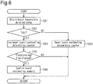
Fig. 6 is a flowchart representing the steps of a procedure of overheating anomaly determination for a circuit board. - An anomaly detecting device according to one embodiment will now be described with reference to the attached drawings. The anomaly detecting device is mounted in a control unit of an in-vehicle actuator.
- With reference to
Fig. 1 , a control unit (ECU) 1 includes a drive circuit 3, which outputs driving power based on a power source voltage Vb of the in-vehicle power source (battery) 2. The driving power output by the drive circuit 3 is supplied to an in-vehicle actuator (ACT) 5 such that the operation of theactuator 5 is controlled. - Specifically, the control unit 1 includes an MPU (microprocessor) 7, which is mounted on a
circuit board 6, together with the drive circuit 3. The MPU 7 is operated by control voltage Vcc, which is regulated by a non-illustrated power source circuit. Quantities of states of theactuator 5, to which the control unit 1 supplies driving power, and quantities of states related to the vehicle in which theactuator 5 is installed are input to the MPU 7. Based on the various types of quantities of states, which have been input to the MPU 7, the MPU 7 generates a control signal Sc. The drive circuit 3 is operated in correspondence with the control signal Sc such that the control unit 1 supplies the driving power to theactuator 5. - Specifically, the
actuator 5 has amotor 8, which is rotated by the supplied driving power. Theactuator 5 is used in, for example, a shock absorber of a suspension. The motor electric current amount, the vehicle wheel speed, the steering angle, and the like are input to the MPU 7 as the quantities of states of theactuator 5 and the vehicle. Based on these various types of quantities of states, the MPU 7 generates the control signal Sc for themotor 8. - The drive circuit 3 uses a publicly known PWM inverter, which is formed by connecting multiple switching elements (FETs) together in a bridge-like manner. The control signal Sc, which is generated by the MPU 7 serving as a motor control unit, is input to the drive circuit 3 as a gate on/off signal in response to which the switching elements are operated.
- The control unit 1 also includes a heat sensitive element (thermistor) 10, which is arranged on the
circuit board 6 together with the drive circuit 3. An output signal of the heatsensitive element 10 is input to the MPU 7. Based on the output signal of the heatsensitive element 10, the MPU 7 detects the board temperature T of thecircuit board 6. - That is, the heat
sensitive element 10 and the MPU 7 form atemperature sensor 11. The MPU 7 serving as an anomaly detecting device determines whether thecircuit board 6 is in an overheated state based on the detected board temperature T (board overheating anomaly determination). When the MPU 7 determines that thecircuit board 6 is in an overheated state, the MPU 7 suspends control of the output of driving power. - Further, based on the detected board temperature T, the MPU 7 performs anomaly determination for the heat
sensitive element 10, which configures thetemperature sensor 11, and the connection circuit of the heatsensitive element 10. Also when the MPU 7 detects an anomaly, the MPU 7 suspends the control of the output of driving power. - Specifically, with reference to the flowchart of
Fig. 2 , the MPU 7 detects the board temperature T of thecircuit board 6 based on the output signal of the heat sensitive element 10 (Step 101). The MPU 7 first detects the board temperature T by functioning as thetemperature sensor 11 and then, based on the board temperature T, performs anomaly determination for the heatsensitive element 10, which configures the temperature sensor 11 (Steps 102 to 104). - Specifically, the MPU 7 determines whether there is an anomaly that causes an unchanged state of the output signal of the heat
sensitive element 10, which is a stuck anomaly of the output signal (stuck anomaly determination, Step 102). The MPU 7 then determines whether there is a break anomaly in the heat sensitive element 10 (break anomaly determination, Step 103) and whether there is a short-circuit anomaly (short-circuit anomaly determination, Step 104). - Subsequently, based on the result of the anomaly determinations performed in
Steps 102 to 104, the MPU 7 determines whether the heatsensitive element 10 is functioning normally as thetemperature sensor 11, or thetemperature sensor 11 is functioning normally (Step 105). Only when the MPU 7 determines that thetemperature sensor 11 functions normally, or the detected board temperature T is an accurate value (Step 105: YES), the MPU 7 performs board overheating anomaly determination based on the detected board temperature T (Step 106). - That is, if the result of the board overheating anomaly determination performed in
Step 106 does not indicate overheating of the circuit board 6 (Step 107: NO), the MPU 7 performs control of the output of driving power (Step 108). In contrast, if the result of the board overheating anomaly determination indicates overheating of the circuit board 6 (Step 107: YES), the MPU 7 suspends the control of the output of driving power (Step 109). - When the MPU 7 determines that the
temperature sensor 11 is not functioning normally (Step 105: NO), the MPU 7 suspends the control of the output of driving power inStep 109. In this manner, to improve reliability, the control unit 1 carries out fail-safe operation. - More specifically, the MPU 7 performs the calculation procedures of
Steps 101 to 108 at predetermined calculation cycles. Also, in the stuck anomaly determining procedure ofStep 102, the MPU 7 performs operating state determination for the drive circuit 3. Specifically, the MPU 7 determines whether the drive circuit 3 is in a driving state, in which the drive circuit 3 outputs driving power, or a non-driving state, in which the drive circuit 3 does not output the driving power. If the drive circuit 3 is in the non-driving state, the MPU 7 memorizes the detected value Tc of the board temperature T, which is detected at predetermined calculation cycles, as the reference value Tr of the board temperature T in astorage area 12 shown in Fig. 12. - In contrast, when the drive circuit 3 is in the driving state, the MPU 7 reads out the reference value Tr, which is memorized in the
storage area 12, and calculates the difference ΔT between the reference value Tr and the detected value Tc, which is detected at each predetermined calculation cycle. If the absolute value of the difference ΔT is less than or equal to a predetermined threshold value α (|ΔT| ≤ α), the MPU 7 determines that there is a stuck anomaly of the output signal in the heatsensitive element 10, which configures thetemperature sensor 11. - That is, the board temperature T of the
circuit board 6, on which the drive circuit 3 is arranged, starts to increase when the drive circuit 3 starts to output driving power. The temperature change at this time is represented as the difference ΔT between the board temperature T before the drive circuit 3 is switched to the driving state (the reference value Tr) and the board temperature T after the drive circuit 3 is switched to the driving state (the detected value Tc). Therefore, if, despite the fact that the drive circuit 3 is in the driving state, temperature increase of thecircuit board 6 is not detected (|ΔT| ≤ α), the MPU 7 determines that the output signal of the heatsensitive element 10, which is the basis of the detected value Tc, is in an unchanged state and that there is a stuck anomaly of the output signal. - Also, when the stuck anomaly is detected continuously for a predetermined time, the MPU 7 confirms the determination of detection of the stuck anomaly of the output signal. The MPU 7 then determines that the
temperature sensor 11 has an anomaly (Step 105: NO) and suspends the control of the output of driving power (Step 109). - Specifically, in the stuck anomaly determination represented in the flowchart of
Fig. 3 , the MPU 7 first obtains the detected value Tc of the board temperature T at a calculation cycle (Step 201). Then, the MPU 7 determines whether the operating state of the drive circuit 3 is the driving state (Step 202). If the MPU 7 determines that the drive circuit 3 is in the non-driving state (Step 202: NO), the MPU 7 memorizes the detected value Tc of the board temperature T, which is detected inStep 201, in thestorage area 12 as the reference value Tr of the board temperature T (Tr = Tc, Step 203). - In contrast, if the MPU 7 determines that the drive circuit 3 is in the driving state (Step 202: YES), the MPU 7 reads out the reference value Tr of the board temperature T, which is memorized in the storage area 12 (Step 204), and calculates the difference ΔT between the detected value Tc of the board temperature T, which is detected in
Step 201, and the reference value Tr (ΔT = Tc - Tr, Step 205). The MPU 7 then determines whether the absolute value of the difference ΔT is less than or equal to the predetermined threshold value α (Step 206). - If the MPU 7 determines that the absolute value of the difference ΔT between the detected value Tc and the reference value Tr is less than or equal to the predetermined threshold value α (|ΔT| ≤ α, Step 206: YES), the MPU 7 increments a non-illustrated stuck anomaly determining counter (Step 207). In contrast, if the MPU 7 determines that the difference ΔT between the detected value Tc and the reference value Tr exceeds the predetermined threshold value α (Step 206: NO), the MPU 7 resets the stuck anomaly determining counter (Step 208). Similarly, also when the MPU 7 determines that the drive circuit 3 is in the non-driving state (Step 202: NO), the MPU 7 resets the stuck anomaly determining counter.
- As long as the difference ΔT between the detected value Tc and the reference value Tr continues to be less than or equal to the predetermined threshold value α (Step 206: YES) despite the fact that the drive circuit 3 is in the driving state (Step 202: YES), the value of the stuck anomaly determining counter is incremented at each predetermined calculation cycle. When the value of the stuck anomaly determining counter reaches a value representing a predetermined elapsed time, which is set in advance (Step 209: YES), the MPU 7 confirms the determination of detection of the stuck anomaly that has occurred in the heat
sensitive element 10, which configures the temperature sensor 11 (Step 210). - In contrast, when the drive circuit 3 is in the non-driving state (Step S202: NO), the MPU 7 performs the procedure of
Step 203 at each predetermined calculation cycle. In this manner, the reference value Tr of the board temperature T, which is memorized in thestorage area 12, is updated by a new detected value Tc as needed. - Further, in the break anomaly determination, the short-circuit anomaly determination, and the board overheating anomaly determination represented in the corresponding flowcharts of
Figs. 4 to 6 (seeSteps Fig. 2 ), the MPU 7 compares the detected value Tc of the board temperature T with a corresponding one of predetermined thresholds values β1, β2, and γ, which are set in advance. - Specifically, in the break anomaly determination represented by the flowchart of
Fig. 4 , the MPU 7 obtains the detected value Tc of the board temperature T (Step 301) and determines whether the detected value Tc is greater than or equal to a predetermined threshold value β1 (Step 302). If the detected value Tc is greater than or equal to the predetermined threshold value β1 (Tc ≥ β1, Step 302: YES), the MPU 7 determines that there is a break anomaly in the heatsensitive element 10, which configures thetemperature sensor 11, and the connection circuit of the heatsensitive element 10. - Also, in the short-circuit anomaly determination represented by the flowchart of
Fig. 5 , if the detected value Tc of the board temperature T is less than or equal to a predetermined threshold value β2 (Tc ≤ β2, Step 402: YES), the MPU 7 determines that there is a short-circuit anomaly in the heatsensitive element 10, which configures thetemperature sensor 11, and the connection circuit of the heatsensitive element 10. In the board overheating anomaly determination represented by the flowchart ofFig. 6 , if the detected value Tc of the board temperature T is greater than or equal to a predetermined threshold value γ (Tc ≥ γ, Step 502: YES), the MPU 7 determines that thecircuit board 6 is in an overheated state. - Further, as in the case of the above-described stuck anomaly determination, if each of the aforementioned anomalies is detected continuously for a predetermined time, the MPU 7 confirms the determination of detection of the anomaly. Also in this case, the procedure of confirming the anomaly detection based on such continuation for the predetermined time is performed using a dedicated counter.
- In the break anomaly determination represented by the flowchart of
Fig. 4 , if the MPU 7 determines that the detected value Tc of the board temperature T is greater than or equal to the predetermined threshold value β1 (Step 302: YES), the MPU 7 increments a break anomaly determining counter (Step S303). In contrast, if the MPU 7 determines that the detected value Tc is less than the predetermined threshold value β1 (Step 302: NO), the MPU 7 resets the break anomaly determining counter (Step S304). When the value of the break anomaly determining counter reaches the value representing a predetermined elapsed time, which is set in advance (Step 305: YES), the MPU 7 confirms the determination of detection of a break anomaly that has occurred in the heatsensitive element 10, which configures the temperature sensor 11 (Step 306). - In the short-circuit anomaly determination represented by the flowchart of
Fig. 5 , the MPU 7 confirms the determination of detection of a short-circuit anomaly through the steps (Steps 402 to 406) of a procedure similar to the break anomaly determination ofSteps 302 to 306. Also, in the overheating anomaly determination represented by the flowchart ofFig. 6 , the MPU 7 confirms the determination of detection of a board overheating anomaly by the steps (Steps 502 to 506) of a procedure similar to the break anomaly determination ofSteps 302 to 306. Based on the confirmed determination results of anomaly detections, the MPU 7 suspends the control of the output of driving power (seeSteps Fig. 2 ). - The present embodiment has the following advantages.
- (1) The MPU 7, which serves as the anomaly detecting device, performs the operating state determination for the drive circuit 3. When the drive circuit 3 is in the non-driving state, the MPU 7 memorizes the detected value Tc of the board temperature T, which is detected at each predetermined calculation cycle, in the
storage area 12 as the reference value Tr of the board temperature T. In contrast, if the drive circuit 3 is in the driving state, the MPU 7 reads out the reference value Tr, which is memorized in thestorage area 12, and calculates the difference ΔT between the reference value Tr and the detected value Tc, which is detected at each predetermined calculation cycle. When the absolute value of the difference ΔT is less than or equal to the predetermined threshold value α (|ΔT| ≤ α), the MPU 7 determines that there is a stuck anomaly of the output signal in the heatsensitive element 10, which configures thetemperature sensor 11.
In the above-described configuration, even when the drive circuit 3 outputs driving power intermittently and non-periodically, a stuck anomaly of the output signal that has occurred in thetemperature sensor 11 is detected accurately. A stuck anomaly that has occurred after actuation of the vehicle is also detected. That is, an anomaly of thetemperature sensor 11 is detected under a wider range of conditions of use. - (2) When the drive circuit 3 is in the non-driving state, the MPU 7 updates the reference value Tr of the board temperature T, which is memorized in the
storage area 12, to a new detected value Tc as needed. - In the above-described configuration, the board temperature T immediately before the drive circuit 3 starts to output driving power is set to the reference value Tr. This ensures accurate detection of temperature change of the
circuit board 6 caused by output of the driving power. In this manner, highly accurate stuck anomaly determination is constantly performed. As a result, an anomaly of thetemperature sensor 11 is quickly detected under a comparatively wide range of conditions of use. - The above illustrated embodiment may be modified as follows.
- In the above-described embodiment, the MPU 7, which serves as the monitor control unit and the anomaly detecting device, also functions as a calculation processing unit of the
temperature sensor 11, which processes the output signal of the heatsensitive element 10. However, the present invention is not restricted to this and thetemperature sensor 11 may include a dedicated calculation processing unit. - In the above-described embodiment, the MPU 7 configures a drive determining section, a reference value maintaining section, a stuck anomaly detecting section, a break anomaly detecting section, a short-circuit anomaly detecting section, an overheating anomaly detecting section, an anomaly confirming section, and an output suspending section of the anomaly detecting device. However, the present invention is not restricted to this and the anomaly detecting device may be configured independently of the MPU 7, which serves as the motor control unit. Alternatively, the respective components of the anomaly detecting device may be configured separately as multiple calculation processing units.
- In the above-described embodiment, when the drive circuit 3 is in the non-driving state, the MPU 7 updates the reference value Tr of the board temperature T, which is memorized in the
storage area 12, to a new detected value Tc at each predetermined calculation cycle as needed. However, the present invention is not restricted to this and, for example, the reference value Tr may be updated as needed when a specific event occurs. That is, the time for updating the reference value Tr does not necessarily have to be periodical. Alternatively, instead of updating the reference value Vr to a new detected value Tc as needed, the detected value Tc of the board temperature T detected at a specific time may be memorized as the reference value Tr. - In the above-described embodiment, the target of the output of driving power by the drive circuit 3 is the
motor 8 of theactuator 5. However, the target may be any suitable target that changes the temperature of thecircuit board 6 due to the output of driving power. - In the above-described embodiment, the determination of detection of an anomaly is confirmed if the anomaly is detected continuously for a predetermined time. The requirement of such continuation for the predetermined time does not necessarily have to be set. On the other hand, a requirement of continuation for a predetermined time may be added to the operating state determination for the drive circuit 3.
Claims (7)
- An anomaly detecting device comprising:a drive determining section that determines an operating state of a drive circuit arranged on a circuit board;a reference value maintaining section, wherein, when the drive circuit is in a non-driving state, the reference value maintaining section maintains a detected value of a board temperature detected by a temperature sensor arranged on the circuit board as a reference value of the board temperature; anda stuck anomaly detecting section, wherein
when the drive circuit is in a driving state, the stuck anomaly detecting section calculates a difference between the detected value of the board temperature detected by the temperature sensor and the reference value of the board temperature maintained by the reference value maintaining section, and
if an absolute value of the difference is less than or equal to a predetermined threshold value, the stuck anomaly detecting section determines that there is a stuck anomaly of an output signal in the temperature sensor. - The anomaly detecting device according to claim 1, wherein, when the drive circuit is in the non-driving state, the reference value maintaining section updates the reference value, as needed, to the detected value that is newly detected.
- The anomaly detecting device according to claim 1 or 2, further comprising a break anomaly detecting section, wherein, if the detected value of the board temperature detected by the temperature sensor is greater than or equal to a predetermined threshold value, the break anomaly detecting section determines that there is a break anomaly in the temperature sensor.
- The anomaly detecting device according to any one of claims 1 to 3, further comprising a short-circuit anomaly detecting section, wherein, if the detected value of the board temperature detected by the temperature sensor is less than or equal to a predetermined threshold value, the short-circuit anomaly detecting section determines that there is a short-circuit anomaly in the temperature sensor.
- The anomaly detecting device according to any one of claims 1 to 4, further comprising an overheating anomaly detecting section, wherein, if the detected value of the board temperature detected by the temperature sensor is greater than or equal to a predetermined threshold value, the overheating anomaly detecting section determines that the circuit board is in an overheated state.
- The anomaly detecting device according to any one of claims 1 to 5, comprising an anomaly confirming section, wherein, when an anomaly is detected continuously for a predetermined time, the anomaly confirming section confirms determination of detection of the anomaly.
- The anomaly detecting device according to any one of claims 1 to 6, further comprising an output suspending section, wherein, when an anomaly of the temperature sensor is detected, the output suspending section suspends output of driving power by the drive circuit.
Applications Claiming Priority (2)
| Application Number | Priority Date | Filing Date | Title |
|---|---|---|---|
| JP2015051344A JP2016170126A (en) | 2015-03-13 | 2015-03-13 | Anomaly detection device |
| PCT/JP2016/057672 WO2016148034A1 (en) | 2015-03-13 | 2016-03-10 | Abnormality detecting device |
Publications (2)
| Publication Number | Publication Date |
|---|---|
| EP3270131A1 true EP3270131A1 (en) | 2018-01-17 |
| EP3270131A4 EP3270131A4 (en) | 2018-02-28 |
Family
ID=56918935
Family Applications (1)
| Application Number | Title | Priority Date | Filing Date |
|---|---|---|---|
| EP16764864.1A Withdrawn EP3270131A4 (en) | 2015-03-13 | 2016-03-10 | Abnormality detecting device |
Country Status (4)
| Country | Link |
|---|---|
| US (1) | US20180048144A1 (en) |
| EP (1) | EP3270131A4 (en) |
| JP (1) | JP2016170126A (en) |
| WO (1) | WO2016148034A1 (en) |
Cited By (1)
| Publication number | Priority date | Publication date | Assignee | Title |
|---|---|---|---|---|
| WO2019002403A1 (en) * | 2017-06-28 | 2019-01-03 | Valeo Equipements Electriques Moteur | Method for protecting the components of a power electronics module of a starter-alternator system, and system implementing this method |
Families Citing this family (1)
| Publication number | Priority date | Publication date | Assignee | Title |
|---|---|---|---|---|
| JP7134160B2 (en) * | 2019-12-18 | 2022-09-09 | 本田技研工業株式会社 | Gas control device and gas control method |
Family Cites Families (4)
| Publication number | Priority date | Publication date | Assignee | Title |
|---|---|---|---|---|
| JP2009210282A (en) * | 2008-02-29 | 2009-09-17 | Nissan Motor Co Ltd | Temperature measuring device, temperature measuring method, and abnormality detection method of temperature measuring device |
| JP5491889B2 (en) * | 2009-04-02 | 2014-05-14 | 日本特殊陶業株式会社 | Energization control device for vehicle control parts |
| US8965716B2 (en) * | 2010-04-05 | 2015-02-24 | Lear Corporation | Method and apparatus for testing at least one temperature sensor in a vehicle |
| JP5688117B2 (en) * | 2013-05-16 | 2015-03-25 | 富士重工業株式会社 | Temperature sensor diagnostic device |
-
2015
- 2015-03-13 JP JP2015051344A patent/JP2016170126A/en not_active Withdrawn
-
2016
- 2016-03-10 US US15/556,036 patent/US20180048144A1/en not_active Abandoned
- 2016-03-10 EP EP16764864.1A patent/EP3270131A4/en not_active Withdrawn
- 2016-03-10 WO PCT/JP2016/057672 patent/WO2016148034A1/en not_active Ceased
Cited By (2)
| Publication number | Priority date | Publication date | Assignee | Title |
|---|---|---|---|---|
| WO2019002403A1 (en) * | 2017-06-28 | 2019-01-03 | Valeo Equipements Electriques Moteur | Method for protecting the components of a power electronics module of a starter-alternator system, and system implementing this method |
| FR3068528A1 (en) * | 2017-06-28 | 2019-01-04 | Valeo Equipements Electriques Moteur | METHOD FOR PROTECTING COMPONENTS OF AN ELECTRONIC POWER MODULE OF AN ALTERNOMETER-STARTING SYSTEM AND SYSTEM USING THE SAME |
Also Published As
| Publication number | Publication date |
|---|---|
| WO2016148034A1 (en) | 2016-09-22 |
| US20180048144A1 (en) | 2018-02-15 |
| EP3270131A4 (en) | 2018-02-28 |
| JP2016170126A (en) | 2016-09-23 |
Similar Documents
| Publication | Publication Date | Title |
|---|---|---|
| US9511794B2 (en) | Electric power steering system and method for processing fail-safe of electronic control unit | |
| US9772249B2 (en) | Sensor device, motor control device, and electric power steering apparatus | |
| JP4760850B2 (en) | Electric power steering device | |
| JP4848216B2 (en) | Booster circuit, motor drive circuit, and electric power steering control device | |
| JP5355530B2 (en) | Electric power steering device | |
| EP3006307A1 (en) | Electric steering device | |
| JP4177387B2 (en) | Motor control device | |
| KR20150092886A (en) | Steering Controlling System and Method Thereof | |
| JP6441505B2 (en) | Control device and control method of control device | |
| CN110871840B (en) | Vehicle control device | |
| JP5102080B2 (en) | Control device for vehicle motor | |
| US20180048144A1 (en) | Abnormality detecting device | |
| EP3296185A1 (en) | Electric power steering device | |
| JP5163251B2 (en) | Control device for electric power steering device | |
| KR20160119311A (en) | Electronic control apparatus and method for | |
| EP2903151B1 (en) | Device for controlling electric motor | |
| US10926793B2 (en) | Coil temperature estimation | |
| KR20120035780A (en) | Device for controlling voltage of cooling fan motor and method thereof | |
| JP2017188973A5 (en) | ||
| WO2003084798A1 (en) | Motor-driven power steering apparatus | |
| JP4853043B2 (en) | Control device for electric power steering device | |
| KR20150062427A (en) | Method and apparatus for emergency operation in the current sensor failure of motor driving power steering system | |
| JP4792820B2 (en) | Control device for electric power steering device | |
| KR100962954B1 (en) | Electric power steering | |
| JP5196746B2 (en) | Fan drive control method and battery overheat protection device in battery overheat protection device |
Legal Events
| Date | Code | Title | Description |
|---|---|---|---|
| PUAI | Public reference made under article 153(3) epc to a published international application that has entered the european phase |
Free format text: ORIGINAL CODE: 0009012 |
|
| 17P | Request for examination filed |
Effective date: 20170901 |
|
| AK | Designated contracting states |
Kind code of ref document: A1 Designated state(s): AL AT BE BG CH CY CZ DE DK EE ES FI FR GB GR HR HU IE IS IT LI LT LU LV MC MK MT NL NO PL PT RO RS SE SI SK SM TR |
|
| AX | Request for extension of the european patent |
Extension state: BA ME |
|
| A4 | Supplementary search report drawn up and despatched |
Effective date: 20180131 |
|
| RIC1 | Information provided on ipc code assigned before grant |
Ipc: G01K 15/00 20060101ALI20180125BHEP Ipc: G01K 7/24 20060101AFI20180125BHEP |
|
| DAV | Request for validation of the european patent (deleted) | ||
| DAX | Request for extension of the european patent (deleted) | ||
| STAA | Information on the status of an ep patent application or granted ep patent |
Free format text: STATUS: THE APPLICATION IS DEEMED TO BE WITHDRAWN |
|
| 18D | Application deemed to be withdrawn |
Effective date: 20180828 |