EP3270024A1 - Starter air valve with multiple disc valves - Google Patents
Starter air valve with multiple disc valves Download PDFInfo
- Publication number
- EP3270024A1 EP3270024A1 EP17180800.9A EP17180800A EP3270024A1 EP 3270024 A1 EP3270024 A1 EP 3270024A1 EP 17180800 A EP17180800 A EP 17180800A EP 3270024 A1 EP3270024 A1 EP 3270024A1
- Authority
- EP
- European Patent Office
- Prior art keywords
- disc
- valve
- shaft
- assembly
- illustrated embodiment
- Prior art date
- Legal status (The legal status is an assumption and is not a legal conclusion. Google has not performed a legal analysis and makes no representation as to the accuracy of the status listed.)
- Withdrawn
Links
- 239000007858 starting material Substances 0.000 title description 9
- 230000004075 alteration Effects 0.000 description 1
- 229920001971 elastomer Polymers 0.000 description 1
- 239000000806 elastomer Substances 0.000 description 1
- 238000000034 method Methods 0.000 description 1
- 238000012986 modification Methods 0.000 description 1
- 230000004048 modification Effects 0.000 description 1
- 239000003566 sealing material Substances 0.000 description 1
- 238000006467 substitution reaction Methods 0.000 description 1
Images




Classifications
-
- F—MECHANICAL ENGINEERING; LIGHTING; HEATING; WEAPONS; BLASTING
- F16—ENGINEERING ELEMENTS AND UNITS; GENERAL MEASURES FOR PRODUCING AND MAINTAINING EFFECTIVE FUNCTIONING OF MACHINES OR INSTALLATIONS; THERMAL INSULATION IN GENERAL
- F16K—VALVES; TAPS; COCKS; ACTUATING-FLOATS; DEVICES FOR VENTING OR AERATING
- F16K1/00—Lift valves or globe valves, i.e. cut-off apparatus with closure members having at least a component of their opening and closing motion perpendicular to the closing faces
- F16K1/16—Lift valves or globe valves, i.e. cut-off apparatus with closure members having at least a component of their opening and closing motion perpendicular to the closing faces with pivoted closure-members
- F16K1/18—Lift valves or globe valves, i.e. cut-off apparatus with closure members having at least a component of their opening and closing motion perpendicular to the closing faces with pivoted closure-members with pivoted discs or flaps
- F16K1/22—Lift valves or globe valves, i.e. cut-off apparatus with closure members having at least a component of their opening and closing motion perpendicular to the closing faces with pivoted closure-members with pivoted discs or flaps with axis of rotation crossing the valve member, e.g. butterfly valves
- F16K1/221—Lift valves or globe valves, i.e. cut-off apparatus with closure members having at least a component of their opening and closing motion perpendicular to the closing faces with pivoted closure-members with pivoted discs or flaps with axis of rotation crossing the valve member, e.g. butterfly valves specially adapted operating means therefor
-
- F—MECHANICAL ENGINEERING; LIGHTING; HEATING; WEAPONS; BLASTING
- F16—ENGINEERING ELEMENTS AND UNITS; GENERAL MEASURES FOR PRODUCING AND MAINTAINING EFFECTIVE FUNCTIONING OF MACHINES OR INSTALLATIONS; THERMAL INSULATION IN GENERAL
- F16K—VALVES; TAPS; COCKS; ACTUATING-FLOATS; DEVICES FOR VENTING OR AERATING
- F16K39/00—Devices for relieving the pressure on the sealing faces
- F16K39/02—Devices for relieving the pressure on the sealing faces for lift valves
- F16K39/028—Devices for relieving the pressure on the sealing faces for lift valves with pivoted closure members, e.g. butterfly valves
-
- F—MECHANICAL ENGINEERING; LIGHTING; HEATING; WEAPONS; BLASTING
- F16—ENGINEERING ELEMENTS AND UNITS; GENERAL MEASURES FOR PRODUCING AND MAINTAINING EFFECTIVE FUNCTIONING OF MACHINES OR INSTALLATIONS; THERMAL INSULATION IN GENERAL
- F16K—VALVES; TAPS; COCKS; ACTUATING-FLOATS; DEVICES FOR VENTING OR AERATING
- F16K1/00—Lift valves or globe valves, i.e. cut-off apparatus with closure members having at least a component of their opening and closing motion perpendicular to the closing faces
- F16K1/16—Lift valves or globe valves, i.e. cut-off apparatus with closure members having at least a component of their opening and closing motion perpendicular to the closing faces with pivoted closure-members
- F16K1/18—Lift valves or globe valves, i.e. cut-off apparatus with closure members having at least a component of their opening and closing motion perpendicular to the closing faces with pivoted closure-members with pivoted discs or flaps
- F16K1/22—Lift valves or globe valves, i.e. cut-off apparatus with closure members having at least a component of their opening and closing motion perpendicular to the closing faces with pivoted closure-members with pivoted discs or flaps with axis of rotation crossing the valve member, e.g. butterfly valves
- F16K1/223—Lift valves or globe valves, i.e. cut-off apparatus with closure members having at least a component of their opening and closing motion perpendicular to the closing faces with pivoted closure-members with pivoted discs or flaps with axis of rotation crossing the valve member, e.g. butterfly valves with a plurality of valve members
-
- F—MECHANICAL ENGINEERING; LIGHTING; HEATING; WEAPONS; BLASTING
- F16—ENGINEERING ELEMENTS AND UNITS; GENERAL MEASURES FOR PRODUCING AND MAINTAINING EFFECTIVE FUNCTIONING OF MACHINES OR INSTALLATIONS; THERMAL INSULATION IN GENERAL
- F16K—VALVES; TAPS; COCKS; ACTUATING-FLOATS; DEVICES FOR VENTING OR AERATING
- F16K1/00—Lift valves or globe valves, i.e. cut-off apparatus with closure members having at least a component of their opening and closing motion perpendicular to the closing faces
- F16K1/16—Lift valves or globe valves, i.e. cut-off apparatus with closure members having at least a component of their opening and closing motion perpendicular to the closing faces with pivoted closure-members
- F16K1/18—Lift valves or globe valves, i.e. cut-off apparatus with closure members having at least a component of their opening and closing motion perpendicular to the closing faces with pivoted closure-members with pivoted discs or flaps
- F16K1/22—Lift valves or globe valves, i.e. cut-off apparatus with closure members having at least a component of their opening and closing motion perpendicular to the closing faces with pivoted closure-members with pivoted discs or flaps with axis of rotation crossing the valve member, e.g. butterfly valves
- F16K1/226—Shaping or arrangements of the sealing
- F16K1/2261—Shaping or arrangements of the sealing the sealing being arranged on the valve member
-
- F—MECHANICAL ENGINEERING; LIGHTING; HEATING; WEAPONS; BLASTING
- F16—ENGINEERING ELEMENTS AND UNITS; GENERAL MEASURES FOR PRODUCING AND MAINTAINING EFFECTIVE FUNCTIONING OF MACHINES OR INSTALLATIONS; THERMAL INSULATION IN GENERAL
- F16K—VALVES; TAPS; COCKS; ACTUATING-FLOATS; DEVICES FOR VENTING OR AERATING
- F16K31/00—Actuating devices; Operating means; Releasing devices
- F16K31/02—Actuating devices; Operating means; Releasing devices electric; magnetic
- F16K31/04—Actuating devices; Operating means; Releasing devices electric; magnetic using a motor
- F16K31/05—Actuating devices; Operating means; Releasing devices electric; magnetic using a motor specially adapted for operating hand-operated valves or for combined motor and hand operation
- F16K31/055—Actuating devices; Operating means; Releasing devices electric; magnetic using a motor specially adapted for operating hand-operated valves or for combined motor and hand operation for rotating valves
Definitions
- the subject matter disclosed herein relates to air valves, and more particularly, to starter air valves for aircraft engines.
- the aircraft engine may experience a bowed rotor condition which requires the aircraft engine to be cooled by drawing fan air through the aircraft engine by motoring the aircraft engine at a sub-idle speed.
- Starter air valves are used within aircraft to selectively provide airflow to the air turbine starter of aircraft engine to rotate the aircraft engine at a desired speed. However, if the starter air valve fails to open, the manual override cannot provide a controlled amount of airflow to maintain the desired sub-idle speed to adequately cool the aircraft engine while avoiding damage from higher speed operation.
- a disc assembly for use in an air valve with a valve body includes an outer disc with a concentric opening therethrough and an outer seal area, the outer seal area to selectively seal against the valve body, and an inner disc disposed in the concentric opening of the outer disc, the inner disc to selectively seal against the outer disc.
- an air valve includes a valve body, and a disc assembly, including an outer disc with a concentric opening therethrough and an outer seal area, the outer seal area to selectively seal against the valve body, and an inner disc disposed in the concentric opening of the outer disc, the inner disc to selectively seal against the outer disc.
- FIG. 1 shows an air valve 100.
- the air valve 100 includes a valve actuator 102, a valve body 104, a manual override interface 106, and a butterfly valve assembly 110.
- the air valve 100 can selectively provide airflow 101 to an air turbine starter of an aircraft engine.
- the manual override interface 106 can be utilized to provide a desired airflow to the air turbine starter of the aircraft engine to motor the aircraft engine at sub-idle speed to cool the aircraft engine.
- the air valve 100 allows for an operator to manually provide a desired amount of airflow to cool the engine in response to the bowed rotor condition while avoiding rubbing and other damage from an excessive aircraft engine motoring speed.
- the airflow 101 flows through the valve body 104. Airflow 101 through the valve body 101 is controlled by the butterfly valve assembly 110 disposed therein.
- the butterfly valve assembly 110 includes an outer valve disc 120 and an inner valve disc 130.
- the butterfly valve assembly utilizes multiple valve discs sized for a desired flow area needed to achieve a desired flow rate.
- the inner valve disc 130 is sized to provide a desired sub-idle motoring speed to cool an engine during a bowed rotor condition.
- multiple valve disc sizes can be utilized to achieve the desired range of targeted flow rates and pressures.
- by utilizing the outer valve disc 120 and the inner valve disc 130 manual operation of the air valve 100 can provide a desired flow rate while avoiding any potential damage.
- the outer valve disc 120 is shown.
- the outer valve disc 120 includes an outer seal area 119, a concentric hole 125, a shaft hole 122, and a through hole 128.
- the outer valve disc 120 can seal the outer seal area 119 against the valve body 104, shown in FIG. 1 .
- the outer valve disc 120 is rotated by an outer disc shaft 126.
- the shaft hole 122 can receive the outer disc shaft 126. Torque can be transferred to the outer valve disc 120 through the pin 124. In the illustrated embodiment, the pin 124 is received in the pin hole 123.
- the outer disc shaft 126 can be affixed in any suitable manner.
- the outer disc shaft 126 is a spring loaded shaft to bias the outer valve disc 120 to a closed position. In the illustrated embodiment, the outer disc shaft 126 is coupled to the valve actuator 102, shown in FIG. 1 .
- the valve actuator 102 can rotate the outer valve disc 120.
- the valve actuator 102 can be any suitable actuator.
- the valve actuator 102 can rotate the outer valve disc 120 to provide an airflow sufficient to provide a full start condition for an aircraft engine.
- the valve actuator 102 to selectively rotate the outer valve disc 120 to a known position to provide a desired airflow to the air turbine starter of the aircraft engine to motor the aircraft engine at sub-idle speed to cool the aircraft engine.
- the outer valve disc 120 includes a concentric hole 125 to allow the inner valve disc 130 therethrough.
- the outer valve disc 120 can include a seal land 121 disposed around the edge of the concentric hole 125.
- the seal land 121 allows for the inner valve disc 130 to seal against the concentric hole 125 and further transfer torque from the inner valve disc 130 to the outer valve disc 120.
- the outer valve disc 120 further includes a through hole 128 to allow the inner disc shaft 136 to pass through the outer valve disc 120.
- the inner valve disc 130 is shown.
- the inner valve disc 130 includes a disc seal 138 and a shaft hole 132.
- the inner valve disc 130 can seal the disc seal 138 against the seal land 121.
- the disc seal 138 is any suitable sealing material, including any suitable elastomer.
- the inner valve disc 130 is rotated by an inner disc shaft 136.
- the shaft hole 132 can receive the inner disc shaft 136. Torque can be transferred to the inner valve disc 130 through the pin 134.
- the pin 134 is received in the pin hole 133.
- the inner disc shaft 136 can be affixed in any suitable manner.
- the inner disc shaft 136 is a spring loaded shaft to bias the inner valve disc 130 to a closed position.
- the inner disc shaft 136 passes through the through hole 128 of the outer disc 120.
- the inner disc shaft 136 is coupled to the manual override interface 106, shown in FIG. 1 .
- the valve actuator 102 may fail to actuate the outer valve disc 120.
- the manual override interface 106 allows a technician to manually rotate the inner valve disc 130 and the outer valve disc 120.
- the manual override interface 106 is a manual wrenching feature, allowing a technician to use a tool to manually rotate the inner disc shaft 136, and therefore the inner valve disc 130 and the outer valve disc 120.
- the inner valve disc 130 is shown rotated 70 degrees by the manual override interface 106.
- the concentric hole 125 allows flow therethrough to allow a desired air flow.
- the resulting airflow can be provided to the air turbine starter of the aircraft engine to motor the aircraft engine at sub-idle speed to cool the aircraft engine in response to a bowed rotor condition.
- the size of the inner valve disc 130 allows a technician to provide a desired flow rate when utilizing the manual override interface 106.
- the inner valve disc 130 is shown rotated a total of 410 degrees by the manual override interface 106.
- the inner valve disc 130 has rotated within the concentric hole 125 and has engaged the seal land 121 to transmit rotation to the outer valve disc 120 to drive the outer valve disc 120 open.
- the outer valve disc 120 is rotated 70 degrees to open relative to the valve body 104.
- the opening of the outer valve disc 120 allows flow through the valve body 104 to allow a greater air flow.
- the resulting airflow can provide a full start condition for an aircraft engine initiated by the manual override interface 106.
Landscapes
- Engineering & Computer Science (AREA)
- General Engineering & Computer Science (AREA)
- Mechanical Engineering (AREA)
- Lift Valve (AREA)
- Taps Or Cocks (AREA)
Abstract
Description
- The subject matter disclosed herein relates to air valves, and more particularly, to starter air valves for aircraft engines.
- After engine operation and shut down, the aircraft engine may experience a bowed rotor condition which requires the aircraft engine to be cooled by drawing fan air through the aircraft engine by motoring the aircraft engine at a sub-idle speed. Starter air valves are used within aircraft to selectively provide airflow to the air turbine starter of aircraft engine to rotate the aircraft engine at a desired speed. However, if the starter air valve fails to open, the manual override cannot provide a controlled amount of airflow to maintain the desired sub-idle speed to adequately cool the aircraft engine while avoiding damage from higher speed operation.
- According to an embodiment, a disc assembly for use in an air valve with a valve body includes an outer disc with a concentric opening therethrough and an outer seal area, the outer seal area to selectively seal against the valve body, and an inner disc disposed in the concentric opening of the outer disc, the inner disc to selectively seal against the outer disc.
- According to an embodiment, an air valve includes a valve body, and a disc assembly, including an outer disc with a concentric opening therethrough and an outer seal area, the outer seal area to selectively seal against the valve body, and an inner disc disposed in the concentric opening of the outer disc, the inner disc to selectively seal against the outer disc.
- Technical function of the embodiments described above includes an inner disc disposed in the concentric opening of the outer disc, the inner disc to selectively seal against the outer disc.
- Other aspects, features, and techniques of the embodiments will become more apparent from the following description taken in conjunction with the drawings.
- The subject matter is particularly pointed out and distinctly claimed in the claims at the conclusion of the specification. The foregoing and other features, and advantages of the embodiments are apparent from the following detailed description taken in conjunction with the accompanying drawings in which like elements are numbered alike in the FIGURES:
-
FIG. 1 is a partial cross sectional view of one embodiment of an air valve; -
FIG. 2 is a pictorial view of a butterfly valve assembly of the air valve ofFIG. 1 ; -
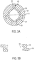
FIG. 3A is a pictorial view of the outer valve disc of the butterfly valve assembly ofFIG. 2 ; -
FIG. 3B is a cross sectional view of the outer valve disc ofFIG. 3A along section line B-B; -
FIG. 4 is a pictorial view of the inner valve disc of the butterfly assembly ofFIG. 2 ; -
FIG. 5 is a pictorial view of the butterfly valve assembly ofFIG. 2 with the inner valve disc rotated open; and -
FIG. 6 is a pictorial view of the butterfly valve assembly ofFIG. 2 with the inner valve disc rotated closed and actuating the outer valve disc. - Referring to the drawings,
FIG. 1 shows anair valve 100. In the illustrated embodiment, theair valve 100 includes avalve actuator 102, avalve body 104, amanual override interface 106, and abutterfly valve assembly 110. In the illustrated embodiment, theair valve 100 can selectively provideairflow 101 to an air turbine starter of an aircraft engine. In the illustrated embodiment, themanual override interface 106 can be utilized to provide a desired airflow to the air turbine starter of the aircraft engine to motor the aircraft engine at sub-idle speed to cool the aircraft engine. Advantageously, theair valve 100 allows for an operator to manually provide a desired amount of airflow to cool the engine in response to the bowed rotor condition while avoiding rubbing and other damage from an excessive aircraft engine motoring speed. - In the illustrated embodiment, the
airflow 101 flows through thevalve body 104.Airflow 101 through thevalve body 101 is controlled by thebutterfly valve assembly 110 disposed therein. - Referring to
FIG. 2 , thebutterfly valve assembly 110 includes anouter valve disc 120 and aninner valve disc 130. In the illustrated embodiment, the butterfly valve assembly utilizes multiple valve discs sized for a desired flow area needed to achieve a desired flow rate. In the illustrated embodiment, theinner valve disc 130 is sized to provide a desired sub-idle motoring speed to cool an engine during a bowed rotor condition. In certain embodiments, multiple valve disc sizes can be utilized to achieve the desired range of targeted flow rates and pressures. Advantageously, by utilizing theouter valve disc 120 and theinner valve disc 130, manual operation of theair valve 100 can provide a desired flow rate while avoiding any potential damage. - Referring to
FIGS. 2 ,3A and 3B , theouter valve disc 120 is shown. In the illustrated embodiment, theouter valve disc 120 includes anouter seal area 119, aconcentric hole 125, ashaft hole 122, and a throughhole 128. In the illustrated embodiment, theouter valve disc 120 can seal theouter seal area 119 against thevalve body 104, shown inFIG. 1 . - In the illustrated embodiment, the
outer valve disc 120 is rotated by anouter disc shaft 126. In the illustrated embodiment, theshaft hole 122 can receive theouter disc shaft 126. Torque can be transferred to theouter valve disc 120 through thepin 124. In the illustrated embodiment, thepin 124 is received in thepin hole 123. In certain embodiments, theouter disc shaft 126 can be affixed in any suitable manner. In certain embodiments, theouter disc shaft 126 is a spring loaded shaft to bias theouter valve disc 120 to a closed position. In the illustrated embodiment, theouter disc shaft 126 is coupled to thevalve actuator 102, shown inFIG. 1 . - In the illustrated embodiment, the
valve actuator 102 can rotate theouter valve disc 120. Thevalve actuator 102 can be any suitable actuator. During starting operations, thevalve actuator 102 can rotate theouter valve disc 120 to provide an airflow sufficient to provide a full start condition for an aircraft engine. During a bowed rotor condition of the aircraft engine, thevalve actuator 102 to selectively rotate theouter valve disc 120 to a known position to provide a desired airflow to the air turbine starter of the aircraft engine to motor the aircraft engine at sub-idle speed to cool the aircraft engine. - In the illustrated embodiment, the
outer valve disc 120 includes aconcentric hole 125 to allow theinner valve disc 130 therethrough. As shown inFIG. 3B , theouter valve disc 120 can include aseal land 121 disposed around the edge of theconcentric hole 125. Theseal land 121 allows for theinner valve disc 130 to seal against theconcentric hole 125 and further transfer torque from theinner valve disc 130 to theouter valve disc 120. In the illustrated embodiment, theouter valve disc 120 further includes a throughhole 128 to allow theinner disc shaft 136 to pass through theouter valve disc 120. - Referring to
FIGS. 2 and4 , theinner valve disc 130 is shown. In the illustrated embodiment, theinner valve disc 130 includes adisc seal 138 and ashaft hole 132. In the illustrated embodiment, theinner valve disc 130 can seal thedisc seal 138 against theseal land 121. In the illustrated embodiment, thedisc seal 138 is any suitable sealing material, including any suitable elastomer. - In the illustrated embodiment, the
inner valve disc 130 is rotated by aninner disc shaft 136. In the illustrated embodiment, theshaft hole 132 can receive theinner disc shaft 136. Torque can be transferred to theinner valve disc 130 through thepin 134. In the illustrated embodiment, thepin 134 is received in thepin hole 133. In certain embodiments, theinner disc shaft 136 can be affixed in any suitable manner. In certain embodiments, theinner disc shaft 136 is a spring loaded shaft to bias theinner valve disc 130 to a closed position. In the illustrated embodiment, theinner disc shaft 136 passes through the throughhole 128 of theouter disc 120. In the illustrated embodiment, theinner disc shaft 136 is coupled to themanual override interface 106, shown inFIG. 1 . - During operation, the
valve actuator 102 may fail to actuate theouter valve disc 120. In the illustrated embodiment, themanual override interface 106 allows a technician to manually rotate theinner valve disc 130 and theouter valve disc 120. In the illustrated embodiment, themanual override interface 106 is a manual wrenching feature, allowing a technician to use a tool to manually rotate theinner disc shaft 136, and therefore theinner valve disc 130 and theouter valve disc 120. - Referring to
FIG. 5 , theinner valve disc 130 is shown rotated 70 degrees by themanual override interface 106. In the illustrated embodiment, theconcentric hole 125 allows flow therethrough to allow a desired air flow. For example, in the illustrated embodiment, with theinner valve disc 130 rotated by 70 degrees, the resulting airflow can be provided to the air turbine starter of the aircraft engine to motor the aircraft engine at sub-idle speed to cool the aircraft engine in response to a bowed rotor condition. Advantageously, the size of theinner valve disc 130 allows a technician to provide a desired flow rate when utilizing themanual override interface 106. - Referring to
FIG. 6 , theinner valve disc 130 is shown rotated a total of 410 degrees by themanual override interface 106. In the illustrated embodiment, theinner valve disc 130 has rotated within theconcentric hole 125 and has engaged theseal land 121 to transmit rotation to theouter valve disc 120 to drive theouter valve disc 120 open. In the illustrated embodiment, theouter valve disc 120 is rotated 70 degrees to open relative to thevalve body 104. In the illustrated embodiment, the opening of theouter valve disc 120 allows flow through thevalve body 104 to allow a greater air flow. For example, in the illustrated embodiment, with theouter valve disc 120 rotated by 70 degrees, the resulting airflow can provide a full start condition for an aircraft engine initiated by themanual override interface 106. - The terminology used herein is for the purpose of describing particular embodiments only and is not intended to be limiting of the embodiments. While the description of the present embodiments has been presented for purposes of illustration and description, it is not intended to be exhaustive or limited to the embodiments in the form disclosed. Many modifications, variations, alterations, substitutions or equivalent arrangement not hereto described will be apparent to those of ordinary skill in the art without departing from the scope of the embodiments. Additionally, while various embodiments have been described, it is to be understood that aspects may include only some of the described embodiments. Accordingly, the embodiments are not to be seen as limited by the foregoing description, but are only limited by the scope of the appended claims.
Claims (11)
- A disc assembly (110) for use in an air valve (100) with a valve body (104), the disc assembly (110) comprising:an outer disc (120) with a concentric opening (125) therethrough and an outer seal area (119), the outer seal area (119) to selectively seal against the valve body (104); andan inner disc (130) disposed in the concentric opening (125) of the outer disc (120), the inner disc (130) to selectively seal against the outer disc (120).
- The disc assembly (110) of claim 1, wherein rotation of the inner disc (130) engages the outer disc (120) to rotate the outer disc (120).
- The disc assembly (110) of claim 1 or 2, wherein the outer disc (120) includes a seal land (121) to receive the inner disc (130).
- The disc assembly (110) of claim 1, 2 or 3, further comprising an outer disc shaft (126) coupled to the outer disc (120) to rotate the outer disc (120), wherein:the outer disc shaft (126) is received in an outer disc shaft hole (122) of the outer disc (120), andthe outer disc shaft (126) is coupled to the outer disc (120) via an outer disc pin (124).
- The disc assembly (110) of any preceding claim, further comprising an inner disc shaft (136) coupled to the inner disc (130) to rotate the inner disc (130), wherein:the inner disc shaft (136) is received in an inner disc shaft hole (132) of the inner disc (130), andthe inner disc shaft (136) is coupled to the inner disc (130) via an inner disc pin (134).
- The disc assembly (110) of claim 5, further comprising a through hole (128) formed through the outer disc (120) to allow the inner disc shaft (130) to pass therethrough.
- The disc assembly of any preceding claim, wherein the inner disc (130) includes a disc seal (138).
- An air valve (100), comprising:a valve body (104); andthe disc assembly (110) of any preceding claim.
- The air valve (100) of claim 8, further comprising:a valve actuator (102) coupled to the outer disc (120); anda manual override interface (106) coupled to the inner disc (130).
- The air valve (100) of claim 9, further comprising an outer disc shaft (126) coupled to the outer disc (120) and the valve actuator (102) to rotate the outer disc (120).
- The air valve of claim 9 or 10, further comprising an inner disc shaft (136) coupled to the inner disc (130) and the manual override interface (106) to rotate the inner disc (130).
Applications Claiming Priority (1)
| Application Number | Priority Date | Filing Date | Title |
|---|---|---|---|
| US15/206,609 US20180010694A1 (en) | 2016-07-11 | 2016-07-11 | Starter air valve with multiple disc valves |
Publications (1)
| Publication Number | Publication Date |
|---|---|
| EP3270024A1 true EP3270024A1 (en) | 2018-01-17 |
Family
ID=59325173
Family Applications (1)
| Application Number | Title | Priority Date | Filing Date |
|---|---|---|---|
| EP17180800.9A Withdrawn EP3270024A1 (en) | 2016-07-11 | 2017-07-11 | Starter air valve with multiple disc valves |
Country Status (2)
| Country | Link |
|---|---|
| US (1) | US20180010694A1 (en) |
| EP (1) | EP3270024A1 (en) |
Families Citing this family (2)
| Publication number | Priority date | Publication date | Assignee | Title |
|---|---|---|---|---|
| CN109667976A (en) * | 2018-12-25 | 2019-04-23 | 兰控阀门执行器江苏有限公司 | A kind of easy to operate electric valve actuator |
| US11994177B2 (en) * | 2021-07-30 | 2024-05-28 | Hamilton Sundstrand Corporation | Universal joint connection for the manual positioning of an angularly offset valve shaft drive |
Citations (5)
| Publication number | Priority date | Publication date | Assignee | Title |
|---|---|---|---|---|
| US2349727A (en) * | 1942-07-06 | 1944-05-23 | David W Hopkins | Valve |
| DD156017A1 (en) * | 1981-02-03 | 1982-07-21 | Joachim Bade | THROTTLE VALVE WITH PRESSURE ELEMENT |
| US4827884A (en) * | 1987-10-02 | 1989-05-09 | Bendix Electronics Limited | Throttle assembly |
| US5657731A (en) * | 1994-11-24 | 1997-08-19 | Hyundai Motor Company | Device for adjusting flow through an intake |
| US20040118464A1 (en) * | 2002-12-18 | 2004-06-24 | Taiwan Semiconductor Manufacturing Co., Ltd. | Multi - phase pressure control valve for process chamber |
-
2016
- 2016-07-11 US US15/206,609 patent/US20180010694A1/en not_active Abandoned
-
2017
- 2017-07-11 EP EP17180800.9A patent/EP3270024A1/en not_active Withdrawn
Patent Citations (5)
| Publication number | Priority date | Publication date | Assignee | Title |
|---|---|---|---|---|
| US2349727A (en) * | 1942-07-06 | 1944-05-23 | David W Hopkins | Valve |
| DD156017A1 (en) * | 1981-02-03 | 1982-07-21 | Joachim Bade | THROTTLE VALVE WITH PRESSURE ELEMENT |
| US4827884A (en) * | 1987-10-02 | 1989-05-09 | Bendix Electronics Limited | Throttle assembly |
| US5657731A (en) * | 1994-11-24 | 1997-08-19 | Hyundai Motor Company | Device for adjusting flow through an intake |
| US20040118464A1 (en) * | 2002-12-18 | 2004-06-24 | Taiwan Semiconductor Manufacturing Co., Ltd. | Multi - phase pressure control valve for process chamber |
Also Published As
| Publication number | Publication date |
|---|---|
| US20180010694A1 (en) | 2018-01-11 |
Similar Documents
| Publication | Publication Date | Title |
|---|---|---|
| US7695355B2 (en) | Integrated housing for fan and alternate flow check valve | |
| CA2688727C (en) | Bypass air scoop for gas turbine engine | |
| US10487740B2 (en) | Multi-flapper check valve without center supports | |
| CN107580653B (en) | Combined butterfly/ball valve | |
| CN102022174B (en) | Mechanical coolant pump | |
| EP2932068B1 (en) | Gas turbine engine with cooling scheme for drive gear system and pitch control | |
| EP3514350A3 (en) | Airflow control for air turbine starter | |
| US9822709B2 (en) | Pneumatic control valve | |
| US20180010694A1 (en) | Starter air valve with multiple disc valves | |
| US20140144407A1 (en) | Sector gear with integrated bushing | |
| EP3385171B1 (en) | Fan bypass and shutoff check valve | |
| US20130118624A1 (en) | Sealed flapper diverter valve | |
| US9957899B1 (en) | Dual inline starter air valve | |
| TWI607185B (en) | Modulating mechanism of centrifugal compressor | |
| US9494087B2 (en) | Stick-resistant engine over-speed shut-down valve | |
| WO2015200468A1 (en) | Forced air blower bypass system | |
| EP3559520B1 (en) | Aviation valve with status indicator | |
| WO2008129921A1 (en) | Evaporative air conditioner | |
| CN111237483A (en) | Butterfly valve | |
| US1490039A (en) | Valve | |
| CN209943578U (en) | Pneumatic limiting accurate control ball valve | |
| EP3346098B1 (en) | Fan air duct assembly for a turbofan engine bleed air system | |
| CN219082383U (en) | Integrated driving equipment | |
| US10519864B2 (en) | Dual inline starter air valve | |
| CN103670716A (en) | Minimum pressure shut-off valve |
Legal Events
| Date | Code | Title | Description |
|---|---|---|---|
| PUAI | Public reference made under article 153(3) epc to a published international application that has entered the european phase |
Free format text: ORIGINAL CODE: 0009012 |
|
| STAA | Information on the status of an ep patent application or granted ep patent |
Free format text: STATUS: THE APPLICATION HAS BEEN PUBLISHED |
|
| AK | Designated contracting states |
Kind code of ref document: A1 Designated state(s): AL AT BE BG CH CY CZ DE DK EE ES FI FR GB GR HR HU IE IS IT LI LT LU LV MC MK MT NL NO PL PT RO RS SE SI SK SM TR |
|
| AX | Request for extension of the european patent |
Extension state: BA ME |
|
| STAA | Information on the status of an ep patent application or granted ep patent |
Free format text: STATUS: REQUEST FOR EXAMINATION WAS MADE |
|
| 17P | Request for examination filed |
Effective date: 20180717 |
|
| RBV | Designated contracting states (corrected) |
Designated state(s): AL AT BE BG CH CY CZ DE DK EE ES FI FR GB GR HR HU IE IS IT LI LT LU LV MC MK MT NL NO PL PT RO RS SE SI SK SM TR |
|
| STAA | Information on the status of an ep patent application or granted ep patent |
Free format text: STATUS: THE APPLICATION IS DEEMED TO BE WITHDRAWN |
|
| 18D | Application deemed to be withdrawn |
Effective date: 20180718 |