EP3269893B1 - Method for pressure-reforming a core layerand a multi-layer-composite comprising zig-zag shaped wood elements - Google Patents
Method for pressure-reforming a core layerand a multi-layer-composite comprising zig-zag shaped wood elements Download PDFInfo
- Publication number
- EP3269893B1 EP3269893B1 EP17180758.9A EP17180758A EP3269893B1 EP 3269893 B1 EP3269893 B1 EP 3269893B1 EP 17180758 A EP17180758 A EP 17180758A EP 3269893 B1 EP3269893 B1 EP 3269893B1
- Authority
- EP
- European Patent Office
- Prior art keywords
- elements
- zigzag
- shaped
- core layer
- wooden
- Prior art date
- Legal status (The legal status is an assumption and is not a legal conclusion. Google has not performed a legal analysis and makes no representation as to the accuracy of the status listed.)
- Active
Links
Images


Classifications
-
- E—FIXED CONSTRUCTIONS
- E04—BUILDING
- E04C—STRUCTURAL ELEMENTS; BUILDING MATERIALS
- E04C2/00—Building elements of relatively thin form for the construction of parts of buildings, e.g. sheet materials, slabs, or panels
- E04C2/30—Building elements of relatively thin form for the construction of parts of buildings, e.g. sheet materials, slabs, or panels characterised by the shape or structure
- E04C2/32—Building elements of relatively thin form for the construction of parts of buildings, e.g. sheet materials, slabs, or panels characterised by the shape or structure formed of corrugated or otherwise indented sheet-like material; composed of such layers with or without layers of flat sheet-like material
- E04C2/322—Building elements of relatively thin form for the construction of parts of buildings, e.g. sheet materials, slabs, or panels characterised by the shape or structure formed of corrugated or otherwise indented sheet-like material; composed of such layers with or without layers of flat sheet-like material with parallel corrugations
-
- E—FIXED CONSTRUCTIONS
- E04—BUILDING
- E04C—STRUCTURAL ELEMENTS; BUILDING MATERIALS
- E04C2/00—Building elements of relatively thin form for the construction of parts of buildings, e.g. sheet materials, slabs, or panels
- E04C2/30—Building elements of relatively thin form for the construction of parts of buildings, e.g. sheet materials, slabs, or panels characterised by the shape or structure
- E04C2/34—Building elements of relatively thin form for the construction of parts of buildings, e.g. sheet materials, slabs, or panels characterised by the shape or structure composed of two or more spaced sheet-like parts
- E04C2/3405—Building elements of relatively thin form for the construction of parts of buildings, e.g. sheet materials, slabs, or panels characterised by the shape or structure composed of two or more spaced sheet-like parts spaced apart by profiled spacer sheets
-
- E—FIXED CONSTRUCTIONS
- E04—BUILDING
- E04C—STRUCTURAL ELEMENTS; BUILDING MATERIALS
- E04C2/00—Building elements of relatively thin form for the construction of parts of buildings, e.g. sheet materials, slabs, or panels
- E04C2/02—Building elements of relatively thin form for the construction of parts of buildings, e.g. sheet materials, slabs, or panels characterised by specified materials
- E04C2/10—Building elements of relatively thin form for the construction of parts of buildings, e.g. sheet materials, slabs, or panels characterised by specified materials of wood, fibres, chips, vegetable stems, or the like; of plastics; of foamed products
- E04C2/12—Building elements of relatively thin form for the construction of parts of buildings, e.g. sheet materials, slabs, or panels characterised by specified materials of wood, fibres, chips, vegetable stems, or the like; of plastics; of foamed products of solid wood
-
- E—FIXED CONSTRUCTIONS
- E04—BUILDING
- E04C—STRUCTURAL ELEMENTS; BUILDING MATERIALS
- E04C2/00—Building elements of relatively thin form for the construction of parts of buildings, e.g. sheet materials, slabs, or panels
- E04C2/30—Building elements of relatively thin form for the construction of parts of buildings, e.g. sheet materials, slabs, or panels characterised by the shape or structure
- E04C2/34—Building elements of relatively thin form for the construction of parts of buildings, e.g. sheet materials, slabs, or panels characterised by the shape or structure composed of two or more spaced sheet-like parts
- E04C2/3405—Building elements of relatively thin form for the construction of parts of buildings, e.g. sheet materials, slabs, or panels characterised by the shape or structure composed of two or more spaced sheet-like parts spaced apart by profiled spacer sheets
- E04C2002/3444—Corrugated sheets
- E04C2002/345—Corrugated sheets with triangular corrugations
-
- E—FIXED CONSTRUCTIONS
- E04—BUILDING
- E04C—STRUCTURAL ELEMENTS; BUILDING MATERIALS
- E04C2/00—Building elements of relatively thin form for the construction of parts of buildings, e.g. sheet materials, slabs, or panels
- E04C2/30—Building elements of relatively thin form for the construction of parts of buildings, e.g. sheet materials, slabs, or panels characterised by the shape or structure
- E04C2/34—Building elements of relatively thin form for the construction of parts of buildings, e.g. sheet materials, slabs, or panels characterised by the shape or structure composed of two or more spaced sheet-like parts
- E04C2/3405—Building elements of relatively thin form for the construction of parts of buildings, e.g. sheet materials, slabs, or panels characterised by the shape or structure composed of two or more spaced sheet-like parts spaced apart by profiled spacer sheets
- E04C2002/3472—Building elements of relatively thin form for the construction of parts of buildings, e.g. sheet materials, slabs, or panels characterised by the shape or structure composed of two or more spaced sheet-like parts spaced apart by profiled spacer sheets with multiple layers of profiled spacer sheets
-
- Y—GENERAL TAGGING OF NEW TECHNOLOGICAL DEVELOPMENTS; GENERAL TAGGING OF CROSS-SECTIONAL TECHNOLOGIES SPANNING OVER SEVERAL SECTIONS OF THE IPC; TECHNICAL SUBJECTS COVERED BY FORMER USPC CROSS-REFERENCE ART COLLECTIONS [XRACs] AND DIGESTS
- Y10—TECHNICAL SUBJECTS COVERED BY FORMER USPC
- Y10T—TECHNICAL SUBJECTS COVERED BY FORMER US CLASSIFICATION
- Y10T156/00—Adhesive bonding and miscellaneous chemical manufacture
- Y10T156/10—Methods of surface bonding and/or assembly therefor
-
- Y—GENERAL TAGGING OF NEW TECHNOLOGICAL DEVELOPMENTS; GENERAL TAGGING OF CROSS-SECTIONAL TECHNOLOGIES SPANNING OVER SEVERAL SECTIONS OF THE IPC; TECHNICAL SUBJECTS COVERED BY FORMER USPC CROSS-REFERENCE ART COLLECTIONS [XRACs] AND DIGESTS
- Y10—TECHNICAL SUBJECTS COVERED BY FORMER USPC
- Y10T—TECHNICAL SUBJECTS COVERED BY FORMER US CLASSIFICATION
- Y10T428/00—Stock material or miscellaneous articles
- Y10T428/24—Structurally defined web or sheet [e.g., overall dimension, etc.]
- Y10T428/24058—Structurally defined web or sheet [e.g., overall dimension, etc.] including grain, strips, or filamentary elements in respective layers or components in angular relation
- Y10T428/24066—Wood grain
-
- Y—GENERAL TAGGING OF NEW TECHNOLOGICAL DEVELOPMENTS; GENERAL TAGGING OF CROSS-SECTIONAL TECHNOLOGIES SPANNING OVER SEVERAL SECTIONS OF THE IPC; TECHNICAL SUBJECTS COVERED BY FORMER USPC CROSS-REFERENCE ART COLLECTIONS [XRACs] AND DIGESTS
- Y10—TECHNICAL SUBJECTS COVERED BY FORMER USPC
- Y10T—TECHNICAL SUBJECTS COVERED BY FORMER US CLASSIFICATION
- Y10T428/00—Stock material or miscellaneous articles
- Y10T428/24—Structurally defined web or sheet [e.g., overall dimension, etc.]
- Y10T428/24628—Nonplanar uniform thickness material
- Y10T428/24669—Aligned or parallel nonplanarities
- Y10T428/24694—Parallel corrugations
- Y10T428/24711—Plural corrugated components
- Y10T428/24719—Plural corrugated components with corrugations of respective components intersecting in plane projection
Definitions
- the present invention relates to a compression-molded core layer, which has zigzag-shaped wooden elements, which is suitable for the production of a multilayer composite or in a multilayer composite, preferably for the production of a lightweight panel, as defined in independent claim 12, as well as a compression-molded multilayer composite, which the Has core layer as defined in independent claim 13.
- the invention also relates to methods for producing the compression-molded core layer as defined in independent claim 1 and the compression-molded multilayer composite as defined in independent claim 2.
- CH 254025 relates to a multilayer composite which has two cover plates and a core layer in between, the core layer having at least one layer of folded veneer.
- the veneer is folded at an angle to the direction of the grain in the wood.
- DE 42 01 201 which is regarded as the closest prior art, relates to semi-finished or finished products made of wood, which are made from plate-shaped elements.
- the platelet-shaped elements can be designed in a zigzag shape. They can be present in a random distribution together with surface elements.
- DE 10 2008 022 806 relates to a lightweight panel with a wave-shaped wood veneer layer.
- the waves can be designed in a zigzag shape.
- the core layer has a loosened structure.
- a force is applied perpendicular to the surface of the multilayer composite, it has a damping effect, since the core layer can be at least partially compressed.
- a disadvantage of these loosened core layers is that they can have poor homogeneity, which is caused by relatively large cavities in the core layer.
- fastening means such as nails, furniture connectors or screws
- these can encounter cavities in the loosened core layers.
- This can result in limited stability of the fastening means in the multilayer composite.
- This in turn can have the result that the stability of the multilayer composite on a carrier, for example on a wall, can be impaired if this is to be fastened to the wall with the aid of nails or screws.
- the production of large-format core layers requires correspondingly large pieces of veneer in high quality.
- An object of the present invention is to provide a compression-deformed core layer and a compression-deformed multilayer composite containing the core layer and the method for their production, which provides improved stability with regard to fastening with nails, furniture connectors or screws or equivalent fastening means to a carrier, for example a Wall.
- a compression-deformed core layer which is suitable for a multilayer composite which has at least one cover layer and the core layer, the cover layer being arranged in such a way that it at least partially covers the core layer and is firmly connected to it, as in Independent claim 12 defines, and the compression-deformed multilayer composite comprising the core layer, wherein the core layer comprises wood elements which have areas which are arranged in a zigzag shape, as defined in independent claim 13.
- Core layer having zigzag-shaped elements made of wood
- a core layer which is suitable for a multilayer composite which has at least one cover layer and a core layer, the cover layer being arranged so that it at least partially covers the core layer and is firmly connected to it, the core layer Has elements made of wood, which have platelet-shaped areas which are arranged in a zigzag shape, a zigzag area of an element with an adjacent zag area of the element forming a common edge between them, such that the element zigzag shaped, and wherein elements in the core layer are arranged such that two such edges of two elements, which may be the same or different from one another, cross each other at an angle that is different from zero, the two elements being fixed to one another at the crossover point are connected.
- core layer which is suitable for a multilayer composite means a core layer which is suitable for producing a multilayer composite or which can be present in a multilayer composite.
- core layer means a layer which has a loosened structure, that is to say has cavities.
- the core layer has elements made of wood, which have platelet-shaped areas. These areas are arranged in a zigzag shape in the element, a zigzag area of an element with an adjacent zag area of the element forming a common edge between them such that the wooden element is designed in a zigzag shape.
- the term "zigzag-shaped” is used synonymously with the term “zigzag-shaped”.
- the zigzag-shaped elements are arranged in the core layer in such a way that two such edges of two elements cross each other at an angle which is different from zero. The two elements are firmly connected to each other at the point where the edges cross.
- a suitable connecting means is preferably an adhesive. Suitable adhesives are known in the prior art.
- cover layer means a layer of a material which preferably serves as a support for the core layer. According to the invention, the cover layer is arranged in such a way that it at least partially covers the core layer and is firmly connected to it.
- the core layer can also be at least partially covered by at least two cover layers and be firmly connected to them.
- the core layer is then preferably located between the two cover layers.
- the cover layer can consist of wood or comprise wood. Other materials such as sheet metal or plastics can also be used.
- cover layer can also completely cover or cover the core layer.
- multilayer composite as used herein means a composite of at least one core layer and at least one outer layer.
- angle other than zero includes that the angle is neither 180 ° nor 360 °.
- element means a component of the core layer or of the multilayer composite.
- platelet-shaped regions includes regions which are designed in the form of surfaces.
- the surfaces can be flat or also uneven, preferably then corrugated.
- elements made of wood which has platelet-shaped regions which are arranged in a zigzag shape includes a platelet-shaped wooden element which is shaped in such a way that it is in a zigzag shape, for example because the Plate is folded around one edge.
- a plate can also be folded twice, in such a way that a zig-zag area follows a zig-zag area, which in turn is followed by a zig-zag area.
- Such a plate can also be folded three times in such a way that a zig-zag area is followed by a zig-zag area, which is followed by a zig-zag area, which in turn is followed by a zig-zag area; etc.
- Edges that are formed by zig-zag areas in a wooden element are aligned parallel to one another.
- zig-zag area and "zig-zag area” are used interchangeably. Both the zig and zag areas are plate-shaped.
- the invention also relates to a compression-deformed core layer in which wooden elements have repeating units of platelet-shaped zig-zag and zag areas which are adjacent to one another, the common edges formed between the areas preferably running parallel to one another.
- Such an arrangement of zigzag areas means that the element is designed or shaped in a zigzag shape.
- edge includes terms such as “transition area between a zig-zag area and the adjacent zag area” .
- This transition area can be an edge which is sharply defined.
- the term also includes an edge which is shaped like a curved surface.
- edge includes a sharp edge in the form of a line as well as a wavy or undulating edge in the form of a curved plane or a curved area between a zig area and a zag area.
- Such edges can be produced by folding a plate-shaped element made of wood.
- the platelet-shaped element is then preferably designed as a veneer.
- Suitable devices for folding are known from the prior art.
- a platelet-shaped wooden element can be passed through a pair of high-speed profile rollers, as in FIG DE 42 01 201 described.
- the folding is preferably carried out essentially transversely to the direction of the wood fiber.
- the folding can be carried out in such a way that folding back of the zigzag-shaped areas in the zig-zag-shaped (shaped) element can at least largely be avoided.
- the edge is produced by cutting.
- wood is cut for this purpose by means of a suitable knife or a suitable cutting edge which is profiled in a zigzag-shaped manner.
- Devices and methods are known from the prior art.
- the folding or cutting is carried out so that the length of the fibers in the resulting wood element is at least twice as long as the thickness of a zig-shaped or zag-shaped area.
- the term “thickness” as used herein means the smallest distance between two surfaces of a zig or a zag area. These surfaces are spaced apart from one another by the thickness of the platelet-shaped zig or zag areas.
- the thickness of the platelet-shaped element is in the range from 0.2 mm to 2 mm.
- the height of the zigzag-shaped wooden elements is typically in the range from 0.8 mm to 8 mm.
- the term "height" is defined as the shortest distance between two imaginary planes between which the zig-zag-shaped wooden element can be arranged, in such a way that the edges, which between zig-zag areas and zig-zag areas of the zig-zag-shaped trained wooden element are formed, lie within one of these levels.
- the thickness of the wooden element is in the range from 0.2 mm to 2 mm and the height of the zigzag-shaped wooden element is in the range from 0.8 mm to 8 mm.
- the thickness of the zigzag-shaped wooden element is at most one tenth of the thickness of the core layer. This ensures sufficient homogeneity of the core layer.
- the dimensions of the zigzag-shaped wooden elements in terms of width and length can vary. Preferred areas are selected from a range of 2 to 20 cm.
- the zigzag-shaped or shaped elements obtained by cutting or folding can be further crushed, if so desired. Suitable cutting devices are known from the prior art.
- the edge or edges formed by the zig-zag area or the zig-zag area or the edges preferably do not run parallel to the preferred direction of the fibers.
- the fibers in two different wooden elements have the same preferred direction.
- the fibers in two different wooden elements have different preferred directions.
- the edge which is formed between a zig-zag area and a zig-zag area of the platelet-shaped wooden element, either does not run parallel to the grain direction of the wooden element, or runs perpendicular to the grain direction of the wooden element.
- this embodiment of the core layer is also characterized in that one or more of the said edges runs or run perpendicular to the preferred direction of the fibers of the platelet-shaped wood element.
- the direction of the fibers in the wooden element runs in the direction of the zigzag-shaped adjoining platelet-shaped areas and perpendicular to their common edges.
- perpendicular to the fiber direction means that a deviation at an angle of approximately up to 30 ° is also possible.
- the core layer according to the invention has first platelet-shaped wooden elements with zigzag-shaped areas and second wooden elements with zig-zag-shaped areas, wherein the first and second zig-zag-shaped wooden elements can be the same or different from one another.
- the first and the second wooden elements differ in terms of their dimensions or the type of wood used. It is preferred that the wood fibers in said first and second elements extend in the same preferred direction.
- more than 50% of the wood elements in the core layer are present in such a way that they are firmly connected to one another, a zig-zag area of an element with an adjacent zig-zag area of the element forming a common edge between them, and elements in the core layer so are arranged so that two such edges of two different elements cross each other at an angle which is different from zero, the two elements being firmly connected to one another at the crossover point.
- the wooden elements are preferably in a random distribution in the core layer.
- the core layer according to the invention has a higher mechanical stability compared to a core layer in which not all wood elements are firmly connected to one another.
- zig areas can cross over with zig areas of other wooden elements in such a way that not the edges but areas of the areas cross or overlap, or said edges can cross or overlap with areas of the zig areas.
- the core layer has flat elements in addition to the zigzag-shaped wooden elements.
- the term “flat” includes terms such as “flat” or “flat or flat” or “flat or flat”. These planar elements can be selected from: wood, paper, metal, plastic, and two or more of them. These planar elements can be glued to said edges of the platelet-shaped wooden elements, which have areas arranged in a zigzag shape. If a region of said zigzag-shaped wooden elements is glued to said flat elements, the internal cohesion of the core layer can be further improved.
- the zigzag-shaped wooden elements are made from veneer or from oriented strand board (OSB) chips.
- the veneer is provided in the form of a sheet or in the form of strips.
- the OSB chips are provided in the form of flakes which have elongated and narrow strands.
- a method for producing a core layer wherein the core layer has platelet-shaped elements made of wood which have areas which are arranged in a zigzag shape, a zigzag area of an element with an adjoining zigzag area of the element form a common edge between them in such a way that the element is designed or shaped in a zigzag shape.
- the elements are arranged in the core layer so that two such edges of two elements that are equal or can be different from each other, intersect at an angle other than zero.
- the fixed connection is preferably carried out by means of an adhesive.
- the two elements which can be the same or different from one another, are firmly connected to one another by flat elements selected from: wood, paper, metal, plastic, and two or more of them, the flat elements with the edges are in turn connected by a suitable connecting means such as preferably an adhesive.
- the arranging of the elements in step (ii) can be accomplished by aligning the wooden elements, which can be done either by hand or by machine.
- the firm bonding in the step (iii) can be facilitated by applying pressure which is preferably in a range from 0.02 MPa to 1.5 MPa, more preferably in a range from 0.01 to 1.0 MPa.
- steps (i) to (iii) can be carried out in the presence of a top layer.
- the method is then preferably carried out in such a way that the wooden elements provided with an adhesive are placed on the top layer in accordance with step (i) and aligned on this in accordance with step (ii).
- This arrangement is then preferably covered by a further cover layer and pressed. This creates a multi-layer composite comprising two cover layers and a core layer located between them.
- the core layer according to the first aspect or produced according to the method of the second aspect is preferably planar.
- Multi-layer composite having at least one top layer and one core layer
- a third aspect relates to a multilayer composite having at least a cover layer and a core layer, the cover layer being arranged such that it at least partially covers the core layer and is firmly connected to it, the core layer being a core layer according to the first aspect and the embodiments described therein or a core layer is produced according to the second aspect and the embodiments described therein.
- the cover layer used in the multilayer composites can have a material selected from the group: veneer, wood board, chipboard, fiber board, plywood board, plastic board, plasterboard, sheet metal, fiber cement board, and two or more thereof.
- the at least one cover layer is preferably flat, i.e. flat.
- the at least one cover layer preferably has a square or rectangular shape.
- the dimensions of the top layer are not limited.
- the width and the length of the at least one cover layer are each preferably in the range from 0.50 m to 5 m, more preferably in the range from 1 to 3 m.
- the side of the core layer which does not yet have a cover layer can then be provided with a cover layer, preferably by gluing to the cover layer.
- a fourth aspect according to the invention relates to a core layer and a multilayer composite containing the core layer, which are not planar.
- the core layer according to the first aspect or produced according to the method of the second aspect and the multilayer composite according to the third aspect are subjected to a step of compression deformation, whereby three-dimensional objects can be produced.
- the core layer or the multilayer composite are deformed in a suitable pressing tool as defined in claim 1 and claim 2 in each case in step (iv). This deformation can take place during the production of the core layer or the multilayer composite as well as afterwards.
- edges of the core layer or of the multilayer composite are deformed, preferably by compression. This makes it possible to seal the cavities at the edges of the core layer or the multilayer composite.
- This compression deformation can be carried out during the joining of the core layers or the multilayer composite, but also after the joining of the core layers or the multilayer composite in a subsequent stage, for example by thermally softening the adhesive at the edges.
- This embodiment has the advantage that sealing of the edges, for example by applying a wooden strip, preferably a veneer strip, can be omitted.
- edge part of the core layer or the multilayer composite When compressing, there is the possibility of providing the edge part of the core layer or the multilayer composite with a convex profile, that is to say a rounded profile. This is often desirable for high-quality furniture components, for example.
- not only the edge area but also further areas of the core layer or of the multilayer composite can be compression-molded in addition to or separately from the edge area.
- a method of manufacturing three-dimensional wooden objects by compression molding is disclosed in DD 271870 and the DE 101 24 912 described.
- the invention relates to a compression-deformed multilayer composite as defined in claim 13, which can be produced by a method which, in addition to steps (i) to (iii), has step (iv): (iv) compression deformation of the multilayer composite according to the third aspect.
- the invention also relates to a compression-molded core layer as defined in claim 12, which can be produced by a method which, in addition to steps (i) to (iii), has step (iv): (iv) compression deformation of the core layer according to the first aspect and the embodiments described therein.
- the invention further relates to the use of the multilayer composite according to the invention or the core layer according to the invention.
- the multilayer composite according to the invention or the core layer according to the invention can preferably be used in applications which allow high mechanical stress at a relatively low weight and / or which require high damping capacity.
- the multi-layer composite or the core layer is used in furniture production, for shelves, for packaging for transport, in interior fittings, in doors and gates, in or as chairs, and in vehicle and shipbuilding.
- the multilayer composite or the core layer can be processed by cutting, sawing, filing and / or drilling using known methods.
- the core layer according to the invention and a multilayer composite which has the core layer according to the invention, for example a lightweight building board, have a high resistance to pressure and stress.
- the core layer according to the invention and the multilayer composite according to the invention produced therefrom are superior to the corresponding core layers or multilayer composites which are produced from industrial waste from chips and fiberboard.
- dimensional changes in the core layer or the multilayer composite under the influence of moisture in particular dimensional changes in the direction of the thickness of the core layer or the multilayer composite, can be negligible due to the negligible dimensional changes in the wood elements in the direction of the fibers.
- fastening means such as nails and screws or furniture connectors find a reliable hold in the core layer according to the invention and the multilayer composite according to the invention, since the structure of the core layer has only small cavities at a comparatively low density, i.e. it is highly homogeneous. A stable attachment to a carrier, for example to a wall, can thus also be achieved.
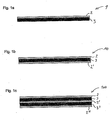
- Fig. 1a shows a cross section of an embodiment of a multilayer composite 1.
- the multilayer composite 1 is designed in such a way that it represents a lightweight construction panel.
- a core layer 3 is covered by the cover layer 2. This is designed as a wood veneer.
- the core layer 3 has wooden elements which are shaped such that a wooden element has two adjacent platelet-shaped areas which are arranged in a zigzag shape such that a zigzag area and the adjacent zag area form a common edge between them , in such a way that the wooden element is designed in a zigzag shape, with elements being arranged in the core layer in such a way that two such edges of two elements, which can be the same or different from one another, intersect at an angle other than zero, wherein the two elements are firmly connected to one another at the crossover point.
- the resulting panel 1 is relatively light and has an aesthetically pleasing appearance due to the veneer cover layer 2.
- the mean density of the core layer 3 is lower than the mean density of the cover layer 2.
- the wooden elements which can be made from folded pieces of veneer, are arranged randomly within the core layer 3. They are connected to one another and to the cover layer 2 by an adhesive. As a result, the lightweight panel can withstand shear forces acting on the layers regardless of the direction of the shear forces in the main plane of the panel. This means that the plate has a homogeneous lateral stability.
- the wooden elements are arranged next to one another and / or one above the other. This enables a dense filling of the core layer, which gives the panel high mechanical stability so that it can be processed further, for example by fitting it with nails and screws or furniture connectors. This also enables stable attachment to a support, such as a wall.
- the wooden elements are arranged randomly in the core layer 3, but can also be arranged in a regular manner, that is to say in a predetermined manner.
- the wooden elements can be arranged in the form of a rule in a group-like manner, i.e. in domains of sub-units of the core layer 3, the wooden elements of a first sub-unit having a first preferred direction and wooden elements of a second sub-unit having a second preferred direction, wherein the first sub-unit is preferably adjacent to the second sub-unit and the first preferred direction is preferably different from or at least partially the same as the second preferred direction.
- a preferred direction can be defined by the edge of a zigzag-shaped wooden element, or can be described by a section of the direction of a wood fiber of a wooden element, or can be described by an edge, for example a section of the long edge of a strip-shaped wooden element (a strip that has been shaped to be zigzag) or by a connecting line between the edges of a zigzag-shaped wooden member formed by the zigzag-shaped areas.
- the multilayer composite 1 according to Fig. 1a has only one cover layer, namely the cover layer 2.
- a composite with only one-sided cover layer has a reduced stability compared to a composite with both-sided cover layers which surround the core layer in a sandwich-like manner. However, it can serve, for example, as an intermediate product for the production of a composite with cover layers on both sides.
- Such a network is in Figure 1b shown.
- Figure 1b shows a cross section of a preferred embodiment of a multilayer composite, namely a cross section of the multilayer composite 10 in the form of a plate.
- a cover layer 2 and a further cover layer 2 '(a bottom layer) are provided, the second cover layer 2' giving the plate additional mechanical stability.
- the visual appearance of the cover layer 2 ′ can be different from that of the cover layer 2.
- Such a composite demonstrates in comparison to the composite Fig. 1a a significantly higher flexural strength and rigidity.
- Figure 1c shows a cross section of a further preferred embodiment of a multilayer composite, namely the multilayer composite 100 in the form of a plate.
- the plate has a cover layer 2, a cover layer 2 'and a cover layer 2 "and, in addition to the core layer 3, a further core layer 3'.
- the zigzag-shaped wooden elements in the core layers 3 and 3 ' can be arranged randomly or can be arranged regularly, that is to say partially regularly (for example in domains) or essentially completely regularly.
- the zigzag-shaped wooden elements in the core layer 3 can have a first preferred direction and the zigzag-shaped wooden elements in the core layer 3 'can have a second preferred direction, the first preferred direction preferably being different from the second preferred direction, or at least is partially equal to the second preferred direction.
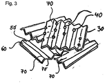
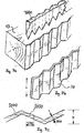
- Fig. 3 shows the arrangement of zigzag-shaped wooden elements 30 in the core layer 3, 3 'of a preferred embodiment of a multilayer composite 1, 10, 100 Form edge 70 between them.
- the arrangement of the zigzag-shaped wooden elements 30 is random. Therefore, the contact surface 40 between adjacent wooden elements is a point 40.
- the wooden elements When arranging and subsequent gluing, the wooden elements usually have point-like connection points 40 on the edges 70 intersecting at different angles. During the moderate compression, these connection points again partially press into one another by upsetting and thus enable the structure to be evened out. Depending on the degree of compaction, a high to medium proportion of voids remains.
- the core layer is more anisotropic, which implies anisotropic mechanical characterization of the resulting plate.
- the resulting structure is a random framework, the framework bars of which consist of parallel-fiber, high-load-bearing wood.
- the upset, articulated rod connections are, as is generally known in trusses, not weak points, since a truss allows joints. Adequate bonding of the connection points is a prerequisite in order to be able to absorb longitudinal forces.
- the very low swelling of the lightweight construction panel in the event of moisture changes is due to the To emphasize practically negligible swelling of the wood along the grain direction. This would make such a board superior to all other wood-based materials made up of flat-lying particles or layers of parallel fibers, such as chipboard and fiberboard, plywood or blockboard.
- the zigzag-shaped wooden elements can be combined with admixed planar, i.e. planar, elements.
- the zigzag-shaped wooden elements are preferably glued to the planar elements.
- proportionally linear connection points arise between the zigzag-shaped elements and the planar elements and thus an increased transverse tensile strength of the lightweight building board.
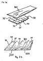
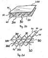
- Fig. 2a shows two components of a further preferred embodiment of a multilayer composite 1, 10, 100 or a core layer 3, 3 'according to the invention.
- the core layer 3, 3 ' comprises plate-shaped zigzag-shaped wooden elements 30, wherein the wooden elements 30 can have a plurality of edges 70 which are formed by adjoining plate-shaped zigzag areas 50 and 60, for example five edges 70 as in wood element 30 of the Fig. 2a .
- a planar element 200 which is designed, for example, as a veneer.
- Figure 2b shows that, according to an advantageous variant, a zigzag-shaped element 30 is glued in a first step to a planar element 200 of a similar or identical format, so that a regular and therefore very rigid framework structure is created in the wooden element 30.
- the planar element 200 can consist of wood veneer, paper, cardboard or comparable, sheet-like materials.
- the zigzag-shaped wooden element 30 and the planar element 200 form cavities 300.
- This framework of the element formed from the planar element 200 and the zigzag-shaped element 30 is fully retained during the later pressing to form a light core. Alone at the connection points of these Lattice-shaped elements are densified locally depending on their location. A high proportion of void space 300 thus remains in the core, which cannot be filled by neighboring elements.
- This embodiment defines a core layer 3, 3 'which is suitable for a multilayer composite 1, 10, 100 which has at least one cover layer 2, 2', 2 "and one core layer 3, 3 ', the cover layer 2, 2', 2 ′′ is arranged so that it at least partially covers the core layer 3, 3 'and is firmly connected to it, the core layer 3, 3' having elements 30 made of wood, which have platelet-shaped areas that are arranged in a zigzag are, wherein a zigzag area 50 of an element with an adjacent zag area 60 of the element 30 form a common edge 70 between them, such that the element 30 is formed in a zigzag shape, and wherein elements 30 in the core layer 3 , 3 'are arranged in such a way that two such edges 70 of two zigzag-shaped elements 30 cross each other at an angle which is different from zero, the two zig-zag-shaped elements 30 being fixed at the crossing point are interconnected; each zigzag-shaped wooden element 30 being glued to a planar element 200
- Elements according to Figure 2b having a zigzag-shaped element 30 and a planar element 200 can be present in a random distribution in the core layer 3, 3 '.
- This embodiment defines a core layer 3, 3 'which is suitable for a multilayer composite 1, 10, 100 which has at least one cover layer 2, 2', 2 "and one core layer 3, 3 ', the cover layer 2, 2', 2 ′′ is arranged in such a way that it at least partially covers the core layer 3, 3 ′ and is firmly attached to it
- the core layer 3, 3 ' has elements 30 made of wood, which have platelet-shaped areas which are arranged in a zigzag shape, a zigzag area 50 of an element 30 having an adjoining zigzag area 60 of the element 30 Form common edge 70 between them, such that the elements 30 are formed in a zigzag shape, and wherein zigzag-shaped elements 30 are arranged in the core layer 3, 3 'so that two such edges 70 of two zigzag zigzag-shaped elements 30 intersect at an angle other than zero, the two zig-zag-shaped elements 30 being firmly connected to one another at the point of intersection; wherein the core layer 3, 3 'has at
- the cavities 300 are formed by the zigzag-shaped regions 50 and 60 in the zigzag-shaped element 30 together with the planar elements 200.
- Figure 2c shows that a zigzag-shaped wooden element 30 can also be glued on both sides with planar elements 200 with the formation of cavities 300.
- This embodiment defines a core layer 3, 3 'which is suitable for a multilayer composite 1, 10, 100 which has at least one cover layer 2, 2', 2 "and one core layer 3, 3 ', the cover layer 2, 2', 2 ′′ is arranged so that it at least partially covers the core layer 3, 3 'and is firmly connected to it, the core layer 3, 3' having elements 30 made of wood, which have platelet-shaped areas that are arranged in a zigzag are, wherein a zigzag area 50 of an element 30 with an adjacent zag area 60 of the element 30 form a common edge 70 between them, such that the element 30 is formed in a zigzag shape, and wherein elements 30 are in the core layer 3, 3 'are arranged such that two such edges 70 of two zigzag-shaped elements 30 cross each other at an angle that is different from zero, the two zig-zag-shaped elements 30 at the Crossing points are firmly connected to each other; wherein the core layer 3, 3 'has at least one zigzag-shaped wooden element
- Fig. 2d shows that a plurality of zigzag-shaped wooden elements 30 can be connected alternately with planar elements 200 to form cavities 300, a planar element 200 separating two zigzag-shaped wooden elements 30 from one another.
- This embodiment defines a core layer 3, 3 'which is suitable for a multilayer composite 1, 10, 100 which has at least one cover layer 2, 2', 2 "and one core layer 3, 3 ', the cover layer 2, 2', 2 ′′ is arranged so that it at least partially covers the core layer 3, 3 'and is firmly connected to it, the core layer 3, 3' having elements 30 made of wood, which have platelet-shaped areas that are arranged in a zigzag are, wherein a zigzag region 50 of an element 30 with an adjacent zag region 60 of the element 30 form a common edge 70 between them, such that the element 30 is zigzag-shaped, and zigzag-shaped formed elements 30 are arranged in the core layer such that two such edges 70 of two zigzag-shaped elements 30 cross each other at an angle that is different from zero, the two zig-zag-shaped elements 30 at the Crossing points are firmly connected to each other; two zigzag-shaped elements 30 being glued to a planar element 200 in such a way
- Elements according to Fig. 2d having a plurality of zigzag-shaped wooden elements 30 alternating with planar elements 200 with the formation of Cavities 300, with a planar element 200 separating two zigzag-shaped wooden elements 30 from one another, can be present in a random distribution in the core layer.
- a planar element 200 separating two zig-zag-shaped wooden elements 300 from each other can be present together with elements 30, preferably in a random distribution .
- This embodiment defines a core layer 3, 3 'which is suitable for a multilayer composite 1, 10, 100 which has at least one cover layer 2, 2', 2 "and one core layer 3, 3 ', the cover layer 2, 2', 2 ′′ is arranged so that it at least partially covers the core layer 3, 3 'and is firmly connected to it, the core layer 3, 3' having elements 30 made of wood, which have platelet-shaped areas that are arranged in a zigzag are, wherein a zigzag area 50 of an element 30 with an adjacent zag area 60 of the element 30 form a common edge 70 between them, such that the element 30 is formed in a zigzag shape, and in a zigzag shape formed elements 30 are arranged in the core layer such that two such edges 70 of two zigzag-shaped elements 30 cross each other at an angle that is different from zero, the two zig-zag-shaped elements 30 at de r crossover points are firmly connected to each other; wherein the core layer 3, 3 'has at least one element which has two
- zigzag-shaped wooden elements 30 together with elements according to Figure 2b and after Figure 2c and after Fig. 2d are present in the core layer 3, 3 '.
- the elements are then preferably arranged or distributed randomly in the core layer.
- zigzag-shaped wooden elements 30 together with elements according to Figure 2c and after Fig. 2d are present in the core layer 3, 3 '.
- the elements are then preferably arranged or distributed randomly in the core layer.
- zigzag-shaped wooden elements 30 together with elements according to Figure 2b and after Fig. 2d are present in the core layer 3, 3 '.
- the elements are then preferably arranged or distributed randomly in the core layer.
- Zigzag-shaped wooden elements combined with or without planar wooden elements, can also be mixed with conventional wooden material elements such as wood chips or wood fibers to form a lightweight core.
- This glued mixture can be pressed into a light wood-based panel, which has a further increased homogeneity.
- the applicability of existing technologies, e.g. chipboard production, is particularly advantageous, whereby panels with a very much lower bulk density than with conventional panel production are possible.
- Fig. 4 shows the arrangement of zigzag-shaped wooden elements 30 'of the core layer 3, 3' on a cover layer 20 'of a further preferred embodiment of a multilayer composite 1, 10, 100.
- the arrangement of the wooden elements is random, which implies an anisotropic mechanical characterization of the resulting plate.
- a wooden element 30 ′ is a strip-shaped, zigzag-shaped element which has only one edge 70 between adjacent zigzag and zag regions 50 and 60.
- a strip-shaped element is an element whose length is greater than the width, expressed by a factor c, where c is preferably between the upper and lower boundaries according to ⁇ 2; 3; 5 ⁇ ⁇ c ⁇ 3;5;8th;10; 20 ⁇ lies.
- the element can also have a plurality of adjoining zig and zag regions, so that it has a plurality of edges 70.
- Figure 5a shows a cross section of a zigzag-shaped wooden element 7 of a core layer of a further preferred embodiment of a multilayer composite according to the invention, for example the board according to the invention.
- the edge section 7 'formed between a zig-zag area and a zig-zag area has a sharp edge.
- the wooden element 7 has only one edge section, but can also have several edge sections, as indicated by the dotted lines.
- Figure 5b shows a cross section of a zigzag-shaped wooden element 8 of a core layer of a further preferred embodiment of a multilayer composite.
- the edge area 8 'does not form a sharp edge but rather a curved edge in the form of a curved plane which can extend up to the height H of the wooden element.
- the wood element 8 has only one edge section, but can have several edge sections, as indicated by the dotted lines.
- Figures 6a and 6b show a device with which zigzag-shaped wooden elements can be produced by folding.
- Fig.6a shows the side view of the device used for the folding,
- Figure 6b the view in the direction of travel.
- veneer or veneer-like elements such as OSB chips with a production-related wood moisture content of at least 30% run into a cutting unit known from the prior art, the wood fiber direction runs transversely to the transport direction.
- This cutting unit separates the veneer or the OSB chips into a band or wooden elements with a width of optionally 10 to 80 mm.
- This band or wooden elements get into a profiling tool which, starting from the middle, presses in a zigzag profile across the direction of the wood fiber until the entire width is profiled.
- the profiling tool is equipped with a heater, which heats the particles after profiling and dries them to the moisture required for further processing.
- the springback of the profile is limited to a minimum.
- the wooden elements After profiling and drying, the wooden elements pass through a roller gluing station, in which the folded edges are provided on both sides with preferably thermosetting adhesive.
- the adhesive dries quickly on the still hot particles and is reactivated when the particles are pressed together later.
- the profiled wooden elements are cut parallel to the direction of the wood grain into 8 to 80mm long parts. Edge sections with correspondingly smaller lengths are also used, as well as partial widths that arise when the veneer is cut.
- the particles provided with adhesive are sprinkled on a prepared cover layer so that the particles are statistically distributed in terms of direction and position in the surface direction, comparable to other particle materials such as chipboard.
- the plate is produced by pressing with moderate pressure, which leads to contact between the particle edges.
- the hardening of the adhesive can be accelerated by contact heating, high frequency or hot air heating.
- the profiling tool is unheated. After profiling, the still moist particles are glued with a moisture-curing adhesive based on polyurethane and the gluing of zigzag-shaped wooden elements and flat wooden elements. This gluing fixes the zigzag profile. This means that springback is ruled out.
- the parts After gluing, the parts are separated into defined wide parts and finally the truss particles are pressed to form a lightweight panel.
- a 0.6 mm thick, a wood moisture content of 30%, measured transversely to the wood fiber direction, a meter long and 50 mm wide in the fiber direction is zigzag-like in a grid of 5 mm and grippy profiled, 40 mm wide, heated roller 5 guided and, starting in the middle, pressed into the profile by a heated sliding shoe 6.1 following the central profile. This is followed by the sliding shoes 6.2, 6.3, etc., each pressing the adjacent profile into the veneer band until the entire width of the veneer band is profiled.
- the gradual profiling starting from the middle guarantees stress-free forming.
- 0.3 mm thick OSB chips with a length of 200 mm and a width of 30 mm are fed transversely to the transport direction into a cutting unit and divided into 40 mm long wooden elements. These wooden elements pass on to a profiling device according to Example 1, the zig-zag profile of which has a grid of 4 mm.
- the further processing corresponds to Example 1. At the end of the processing, a finely structured and homogeneously structured lightweight wood construction panel with a gross density of 250 kg / m 3 is produced .
- the particular advantage is that production can be largely automated.
- a zigzag-shaped profiled and glued veneer tape according to example 1 is brought together with a flat veneer tape 24 mm wide and glued to it.
- This glued band runs through a pair of gluing rollers in order to provide the profile edges or the outer surface of the flat band with glue.
- particles After passing through a separation station, particles are in the form of a regular framework Figure 2b in front.
- a lightweight wood construction panel with a bulk density of 180 kg / m 3 is produced during pressing.
- Figure 7a shows the production of a zigzag-shaped wooden element by cutting with a knife 1000 from a block of wood 13.
- the knife 1000 used in the production of peeled or sliced veneer or veneer-like chips is profiled in a zigzag shape.
- Figure 7b shows the wooden element obtained, for example wooden element 30. This can then be comminuted, for example in a cutting unit.
- Figure 7c shows a zigzag-shaped wooden element 30 of FIG Figure 7b , the zigzag profile being dimensioned so that the wood fibers 3000 have at least twice the length 4000 compared to the thickness 500 and thus enable good transverse tensile and shear strength.
- the advantage of this variant is the production of profiled parts Parts in a single operation as well as the high constancy of the profiles.
- the wood fibers, which run at an angle to the profile rods, represent a compromise in terms of their strength, as does the greater thickness swelling.
- Figures 8a and 8b show in a further embodiment (example 4) a device for the production of zigzag-shaped wooden elements by cutting.
- Figure 8a shows the side view
- Figure 8b the top view.
- a 400 mm high block of wood 13 is cut off by means of a zigzag profiled knife 1000 with a profile grid dimension of 5 mm profiled veneer 400 of height 11 of 3 mm.
- the thickness of the profiled veneer (500 in Figure 7c ) is 0.5mm.
- Scoring knives 12 are attached to the profile knife 1000 at a distance of 25 mm, which cut the resulting profiled veneer 400 into strips 25 mm wide and 400 mm long.
- a knife disc chipper common in chipboard technology is equipped with zigzag profiled knives with a profile grid dimension of 3 mm, the set chip thickness being 0.3 mm.
- the attached scoring knives have a distance of 20 mm.
- the starting products are round wood cuttings, scrap rolls and other scrap materials.
- the wooden elements produced with this chipper are processed according to Example 4.
- a particular advantage of this technology is that it can be compared with the highly productive manufacture of chipboard, which results in a very cost-effective lightweight wood construction material.
- a veneer peeling machine is equipped with a knife according to example 4.
- the one from a peeling block The produced, appropriately profiled veneer web runs through a veneer dryer, a roller gluing machine and finally a conti press, in which a cardboard web is pressed on.
- This track is then divided into 25 x 25 mm 2 wooden elements using known cutting units, which represent regular frameworks. After sighting and removal of unusable parts, these wooden elements are provided with glue in a glue drum and then pressed to form a wooden construction panel with a bulk density of 200 kg / m 3.
- An advantage here is the usability of inferior wood assortments that are not suitable for the usual veneer production.
- Fig. 9 shows zigzag-shaped wooden elements 30 ′′, which are produced by cutting with a correspondingly profiled knife, which do not have a constant profile thickness. These are characterized by increased compressive strength.
- the cutting direction in the production of the elements can be changed with each new cutting stroke in up to 90 ° offset direction, whereby the geometry and thus the stability of the veneer pieces due to the fiber orientation changes. With a maximum difference of the cutting directions of 90 °, the produced "profiled wood element", depending on the cutting thickness, has a lattice structure
- wood-based materials are particularly suitable as the starting material, which have approximately the same strength properties in different panel directions.
Description
Die vorliegende Erfindung betrifft eine druckverformte Kernschicht, welche zick-zack-förmig ausgebildete Holzelemente aufweist, welche zur Herstellung eines Mehrschichtverbunds oder in einem Mehrschichtverbund geeignet ist, vorzugsweise zur Herstellung einer Leichtbauplatte, wie im unabhängigen Anspruch 12 definiert, sowie einen druckverformten Mehrschichtverbund, welcher die Kernschicht aufweist, wie im unabhängigen Anspruch 13 definiert. Die Erfindung betrifft ferner Verfahren zur Herstellung der druckverformten Kernschicht, wie im unabhängigen Anspruch 1 definiert, und des druckverformten Mehrschichtverbunds, wie im unabhängigen Anspruch 2 definiert.The present invention relates to a compression-molded core layer, which has zigzag-shaped wooden elements, which is suitable for the production of a multilayer composite or in a multilayer composite, preferably for the production of a lightweight panel, as defined in
Es ist bekannt, Verbundmaterialien zur Herstellung von Mehrschichtverbunden zu verwenden, die im Vergleich zu ihrem Gewicht eine relativ hohe mechanische Stabilität aufweisen. Derartige Mehrschichtverbünde werden beispielsweise in Form von Leichtbauplatten verwendet.It is known to use composite materials for the production of multilayer composites which have a relatively high mechanical stability compared to their weight. Such multi-layer composites are used, for example, in the form of lightweight panels.
Diesen Mehrschichtverbunden ist gemeinsam, dass die Kernschicht eine aufgelockerte Struktur aufweist. Bei Krafteinwirkung senkrecht zur Oberfläche des Mehrschichtverbunds weist dieser eine dämpfende Wirkung auf, da sich die Kernschicht zumindest teilweise komprimieren lässt. Ein Nachteil dieser aufgelockerten Kernschichten liegt darin, dass sie eine geringe Homogenität aufweisen können, die durch relativ große Hohlräume in der Kernschicht hervorgerufen wird. Dann können beim Einbringen von Befestigungsmitteln, wie beispielsweise Nägeln, Möbelverbinder oder Schrauben, diese auf Hohlräume in den aufgelockerten Kernschichten treffen. Dies kann eine eingeschränkte Stabilität des Befestigungsmittels im Mehrschichtverbund zur Folge haben. Dies kann wiederum dazu führen, dass die Stabilität des Mehrschichtverbunds an einem Träger, beispielsweise an einer Wand, beeinträchtigt werden kann, wenn dieser mit Hilfe von Nägeln oder Schrauben an der Wand befestigt werden soll. Außerdem erfordert die Herstellung großformatiger Kernlagen entsprechend große Furnierstücke in hoher Qualität.What these multilayer composites have in common is that the core layer has a loosened structure. When a force is applied perpendicular to the surface of the multilayer composite, it has a damping effect, since the core layer can be at least partially compressed. A disadvantage of these loosened core layers is that they can have poor homogeneity, which is caused by relatively large cavities in the core layer. Then when fastening means, such as nails, furniture connectors or screws, are introduced, these can encounter cavities in the loosened core layers. This can result in limited stability of the fastening means in the multilayer composite. This in turn can have the result that the stability of the multilayer composite on a carrier, for example on a wall, can be impaired if this is to be fastened to the wall with the aid of nails or screws. In addition, the production of large-format core layers requires correspondingly large pieces of veneer in high quality.
Eine Aufgabe der vorliegenden Erfindung besteht darin, eine druckverformte Kernschicht und einen druckverformten Mehrschichtverbund enthaltend die Kernschicht und die Verfahren zu ihrer Herstellung bereit zu stellen, welcher eine verbesserte Stabilität bezüglich der Befestigung mit Nägeln, Möbelverbindern oder Schrauben oder äquivalenten Befestigungsmitteln an einen Träger, beispielsweise einer Wand, aufweist.An object of the present invention is to provide a compression-deformed core layer and a compression-deformed multilayer composite containing the core layer and the method for their production, which provides improved stability with regard to fastening with nails, furniture connectors or screws or equivalent fastening means to a carrier, for example a Wall.
Diese Aufgabe wird erfindungsgemäß gelöst mit einer druckverformten Kernschicht, welche für einen Mehrschichtverbund geeignet ist, der mindestens eine Deckschicht und die Kernschicht aufweist, wobei die Deckschicht so angeordnet ist, dass sie die Kernschicht zumindest teilweise bedeckt und mit dieser in fester Verbindung steht, wie im unabhängigen Anspruch 12 definiert, und dem druckverformten Mehrschichtverbund aufweisend die Kernschicht, wobe die Kernschicht Holzelemente aufweist, welche Bereiche aufweisen, die zick-zack-förmig angeordnet sind, wie im unabhängigen Anspruch 13 definiert.This object is achieved according to the invention with a compression-deformed core layer which is suitable for a multilayer composite which has at least one cover layer and the core layer, the cover layer being arranged in such a way that it at least partially covers the core layer and is firmly connected to it, as in
In einem ersten Aspekt wird eine Kernschicht offenbart, welche für einen Mehrschichtverbund geeignet ist, der mindestens eine Deckschicht und eine Kernschicht aufweist, wobei die Deckschicht so angeordnet ist, dass sie die Kernschicht zumindest teilweise bedeckt und mit dieser in fester Verbindung steht, wobei die Kernschicht Elemente aus Holz aufweist, welche plättchenförmige Bereiche aufweisen, die zick-zack-förmig angeordnet sind, wobei ein zick-Bereich eines Elements mit einem angrenzenden zack-Bereich des Elements eine gemeinsame Kante zwischen sich ausbilden, derart, dass das Element zick-zack-förmig ausgebildet ist, und wobei Elemente in der Kernschicht so angeordnet sind, dass zwei derartige Kanten zweier Elemente, die gleich oder verschieden voneinander sein können, sich in einem Winkel überkreuzen, der verschieden von Null ist, wobei die zwei Elemente an der Überkreuzungsstelle fest miteinander verbunden sind.In a first aspect , a core layer is disclosed which is suitable for a multilayer composite which has at least one cover layer and a core layer, the cover layer being arranged so that it at least partially covers the core layer and is firmly connected to it, the core layer Has elements made of wood, which have platelet-shaped areas which are arranged in a zigzag shape, a zigzag area of an element with an adjacent zag area of the element forming a common edge between them, such that the element zigzag shaped, and wherein elements in the core layer are arranged such that two such edges of two elements, which may be the same or different from one another, cross each other at an angle that is different from zero, the two elements being fixed to one another at the crossover point are connected.
Wie in dieser Offenbarung verwendet, bedeutet der Begriff "Kernschicht, welche für einen Mehrschichtverbund geeignet ist" eine Kernschicht, welche zur Herstellung eines Mehrschichtverbunds geeignet ist, oder welche in einem Mehrschichtverbund vorliegen kann.As used in this disclosure, the term “core layer which is suitable for a multilayer composite” means a core layer which is suitable for producing a multilayer composite or which can be present in a multilayer composite.
Der Begriff "Kernschicht", wie hierin verwendet, bedeutet eine Schicht, welche eine aufgelockerte Struktur aufweist, also Hohlräume aufweist. Erfindungsgemäß weist die Kernschicht Elemente aus Holz auf, welche plättchenförmige Bereiche aufweisen. Diese Bereiche sind im Element zick-zack-förmig angeordnet, wobei ein zick-Bereich eines Elements mit einem angrenzenden zack-Bereich des Elements eine gemeinsame Kante zwischen sich ausbilden, derart, dass das Holzelement zick-zack-förmig ausgebildet ist. Der Begriff "zick-zack-förmig ausgebildet" wird synonym zum Begriff "zick-zack-förmig ausgeformt" verwendet. Die zick-zack-förmig ausgebildeten Elemente sind in der Kernschicht so angeordnet sind, dass zwei derartige Kanten zweier Elemente sich in einem Winkel überkreuzen, der verschieden von null ist. An der Überkreuzungsstelle der Kanten sind die zwei Elemente fest miteinander verbunden. Ein geeignetes Verbindungsmittel ist vorzugsweise ein Kleber. Geeignete Kleber sind im Stand der Technik bekannt.The term “core layer”, as used herein, means a layer which has a loosened structure, that is to say has cavities. According to the invention, the core layer has elements made of wood, which have platelet-shaped areas. These areas are arranged in a zigzag shape in the element, a zigzag area of an element with an adjacent zag area of the element forming a common edge between them such that the wooden element is designed in a zigzag shape. The term "zigzag-shaped" is used synonymously with the term "zigzag-shaped". The zigzag-shaped elements are arranged in the core layer in such a way that two such edges of two elements cross each other at an angle which is different from zero. The two elements are firmly connected to each other at the point where the edges cross. A suitable connecting means is preferably an adhesive. Suitable adhesives are known in the prior art.
Der Begriff "Deckschicht", wie hierin verwendet, bedeutet eine Schicht eines Materials, welches vorzugsweise als Träger für die Kernschicht dient. Erfindungsgemäß ist die Deckschicht so angeordnet, dass sie die Kernschicht zumindest teilweise bedeckt und mit dieser in fester Verbindung steht. Die Kernschicht kann auch von mindestens zwei Deckschichten zumindest teilweise bedeckt sein und mit diesen in fester Verbindung stehen. Vorzugsweise befindet sich dann die Kernschicht zwischen den beiden Deckschichten. Die Deckschicht kann aus Holz bestehen oder Holz aufweisen. Andere Materialien wie Bleche oder Kunststoffe sind gleichfalls verwendbar.The term “cover layer”, as used herein, means a layer of a material which preferably serves as a support for the core layer. According to the invention, the cover layer is arranged in such a way that it at least partially covers the core layer and is firmly connected to it. The core layer can also be at least partially covered by at least two cover layers and be firmly connected to them. The core layer is then preferably located between the two cover layers. The cover layer can consist of wood or comprise wood. Other materials such as sheet metal or plastics can also be used.
Der Begriff "zumindest teilweise bedeckt", wie hierin verwendet, schließt ein, dass die Deckschicht die Kernschicht auch vollständig überdecken oder bedecken kann.The term “at least partially covered”, as used herein, includes that the cover layer can also completely cover or cover the core layer.
Der Begriff "Mehrschichtverbund", wie hierin verwendet, bedeutet einen Verbund aus mindestens einer Kernschicht und mindestens einer Deckschicht.The term “multilayer composite” as used herein means a composite of at least one core layer and at least one outer layer.
Der Begriff "Winkel, welcher verschieden von Null ist", wie hierin verwendet, schließt ein, dass der Winkel weder 180° noch 360° beträgt.The term “angle other than zero” as used herein includes that the angle is neither 180 ° nor 360 °.
Der Begriff "Element", wie hierin verwendet, bedeutet ein Bauteil der Kernschicht oder des Mehrschichtverbunds.The term “element”, as used herein, means a component of the core layer or of the multilayer composite.
Der Begriff "plattchenförmige Bereiche", wie hierin verwendet, schließt Bereiche ein, die in Form von Flächen ausgebildet sind. Die Flächen können eben oder auch uneben, vorzugsweise dann gewellt sein.The term “platelet-shaped regions”, as used herein, includes regions which are designed in the form of surfaces. The surfaces can be flat or also uneven, preferably then corrugated.
Der Begriff "Elemente aus Holz, welches plättchenförmige Bereiche aufweist, die zick-zack-förmig angeordnet sind", wie hierin verwendet, schließt ein plättchenförmiges Holzelement ein, welches derart geformt ist, dass es zick-zack-förmig ausgebildet vorliegt, etwa weil das Plättchen um eine Kante gefaltet ist. Ein derartiges Plättchen kann auch zweimal gefaltet sein, derart, dass einem zick-Bereich ein zack-Bereich folgt, welchem wiederum ein zick-Bereich folgt. Ein derartiges Plättchen kann auch dreimal gefaltet sein, derart, dass einem zick-Bereich ein zack-Bereich folgt, welchem ein zick-Bereich folgt, welchem wiederum ein zack-Bereich folgt; usw. Vorzugsweise sind Kanten, welche von zick- mit zack-Bereichen in einem Holzelement gebildet werden parallel zueinander ausgerichtet.The term "elements made of wood which has platelet-shaped regions which are arranged in a zigzag shape", as used herein, includes a platelet-shaped wooden element which is shaped in such a way that it is in a zigzag shape, for example because the Plate is folded around one edge. Such a plate can also be folded twice, in such a way that a zig-zag area follows a zig-zag area, which in turn is followed by a zig-zag area. Such a plate can also be folded three times in such a way that a zig-zag area is followed by a zig-zag area, which is followed by a zig-zag area, which in turn is followed by a zig-zag area; etc. Preferably are Edges that are formed by zig-zag areas in a wooden element are aligned parallel to one another.
Die Begriffe "zick-Bereich" und "zack-Bereich" werden austauschbar verwendet. Sowohl der zick- wie auch der zack-Bereich sind plättchenförmig.The terms "zig-zag area" and "zig-zag area" are used interchangeably. Both the zig and zag areas are plate-shaped.
Demzufolge betrifft die Erfindung in einer Ausführungsform auch eine druckverformte Kernschicht, in welcher Holzelemente sich wiederholende Einheiten aus plättchenförmigen zick- und zack-Bereichen aufweisen, die aneinander grenzen, wobei die zwischen den Bereichen ausgebildeten gemeinsamen Kanten vorzugsweise parallel zueinander verlaufen. Durch eine derartige Anordnung von zick- mit zack-Bereichen wird das Element zick-zack-förmig ausgebildet bzw. ausgeformt.Accordingly, in one embodiment, the invention also relates to a compression-deformed core layer in which wooden elements have repeating units of platelet-shaped zig-zag and zag areas which are adjacent to one another, the common edges formed between the areas preferably running parallel to one another. Such an arrangement of zigzag areas means that the element is designed or shaped in a zigzag shape.
Der Begriff "Kante", wie hierin verwendet, schließt Begriffe wie "Übergangsbereich zwischen einem zick- und dem angrenzenden zack-Bereich" ein. Dieser Übergangsbereich kann eine Kante sein, welche scharf ausgeprägt ist. Der Begriff schließt auch eine Kante ein, welche wie eine gekrümmte Fläche ausgestaltet ist. Somit schließt der Begriff "Kante", wie hierin verwendet, eine scharfe Kante in Form einer Linie wie auch eine wellige oder gewellte Kante in der Form einer kurvenförmigen Ebene oder einen gekrümmten Bereich zwischen einem zick-Bereich und einem zack-Bereich ein.The term “edge”, as used herein, includes terms such as “transition area between a zig-zag area and the adjacent zag area” . This transition area can be an edge which is sharply defined. The term also includes an edge which is shaped like a curved surface. Thus, as used herein, the term "edge" includes a sharp edge in the form of a line as well as a wavy or undulating edge in the form of a curved plane or a curved area between a zig area and a zag area.
Derartige Kanten können dadurch erzeugt werden, dass ein plättchenförmiges Element aus Holz gefaltet wird. Vorzugsweise ist dann das plättchenförmige Element als Furnier ausgestaltet.Such edges can be produced by folding a plate-shaped element made of wood. The platelet-shaped element is then preferably designed as a veneer.
Geeignete Vorrichtungen zum Falten sind aus dem Stand der Technik bekannt. Vorzugsweise kann ein plättchenförmiges Holzelement durch ein schnelllaufendes Profilwalzenpaar geleitet werden, wie in
In einer weiteren Ausführungsform wird die Kante hergestellt durch Schneiden. In einer Ausführungsform wird dazu Holz mittels eines geeigneten Messers oder einer geeigneten Schneide, welche in einer zick-zack-förmigen Art und Weise profiliert ist, geschnitten. Vorrichtungen und Verfahren sind aus dem Stand der Technik bekannt.In a further embodiment, the edge is produced by cutting. In one embodiment, wood is cut for this purpose by means of a suitable knife or a suitable cutting edge which is profiled in a zigzag-shaped manner. Devices and methods are known from the prior art.
In einer Ausführungsform wird das Falten oder Schneiden so durchgeführt, dass die Länge der Fasern im resultierenden Holzelement mindestens zweimal so lang ist wie die Dicke eines zick-förmigen oder zack-förmigen Bereichs. Der Begriff "Dicke" wie hierin verwendet, bedeutet den kleinsten Abstand zwischen zwei Oberflächen eines zick- bzw. eines zack-Bereichs. Diese Oberflächen sind durch die Dicke der plättchenförmigen zick- bzw. zack-Bereiche voneinander beabstandet.In one embodiment, the folding or cutting is carried out so that the length of the fibers in the resulting wood element is at least twice as long as the thickness of a zig-shaped or zag-shaped area. The term “thickness” as used herein means the smallest distance between two surfaces of a zig or a zag area. These surfaces are spaced apart from one another by the thickness of the platelet-shaped zig or zag areas.
In einer Ausführungsform liegt die Dicke des plättchenförmigen Elements im Bereich von 0,2 mm bis 2 mm.In one embodiment, the thickness of the platelet-shaped element is in the range from 0.2 mm to 2 mm.
Die Höhe der zick-zack-förmig ausgebildeten Holzelemente liegt typischerweise im Bereich von 0,8 mm bis 8 mm. Der Begriff "Höhe" ist definiert als der kürzeste Abstand zwischen zwei imaginären Ebenen, zwischen welche das zick-zack-förmige Holzelement angeordnet werden kann, derart, dass die Kanten, welche zwischen zick-Bereichen und zack-Bereichen des zick-zack-förmig ausgebildeten Holzelements gebildet werden, innerhalb einer dieser Ebenen liegen.The height of the zigzag-shaped wooden elements is typically in the range from 0.8 mm to 8 mm. The term "height" is defined as the shortest distance between two imaginary planes between which the zig-zag-shaped wooden element can be arranged, in such a way that the edges, which between zig-zag areas and zig-zag areas of the zig-zag-shaped trained wooden element are formed, lie within one of these levels.
In einer Ausführungsform ist die Dicke des Holzelements im Bereich von 0,2 mm bis 2 mm und die Höhe des zick-zack-förmig ausgebildeten Holzelements im Bereich von 0,8 mm bis 8 mm.In one embodiment, the thickness of the wooden element is in the range from 0.2 mm to 2 mm and the height of the zigzag-shaped wooden element is in the range from 0.8 mm to 8 mm.
In einer Ausführungsform beträgt die Dicke des zick-zack-förmig ausgebildeten Holzelements höchstens einem Zehntel der Dicke der Kernschicht. Dies sorgt für eine genügende Homogenität der Kernschicht.In one embodiment, the thickness of the zigzag-shaped wooden element is at most one tenth of the thickness of the core layer. This ensures sufficient homogeneity of the core layer.
Die Abmessungen der zick-zack-förmig ausgebildeten Holzelemente bezüglich Breite und Länge kann variieren. Vorzugsbereiche werden aus einem Bereich von 2 bis 20 cm ausgewählt.The dimensions of the zigzag-shaped wooden elements in terms of width and length can vary. Preferred areas are selected from a range of 2 to 20 cm.
Die durch Schneiden oder Falten erhaltenen zick-zack-förmig ausgebildeten oder ausgeformten Elemente können weiter zerkleinert werden, falls dies erwünscht ist. Geeignete Schneidvorrichtungen sind aus dem Stand der Technik bekannt. Vorzugsweise verläuft oder verlaufen die durch den zick- und zack-Bereich oder die durch die zick- und zack-Bereiche gebildete Kante oder die Kanten nicht parallel zur Vorzugsrichtung der Fasern.The zigzag-shaped or shaped elements obtained by cutting or folding can be further crushed, if so desired. Suitable cutting devices are known from the prior art. The edge or edges formed by the zig-zag area or the zig-zag area or the edges preferably do not run parallel to the preferred direction of the fibers.
In einer Ausführungsform haben die Fasern in zwei verschiedenen Holzelementen die gleiche Vorzugsrichtung.In one embodiment, the fibers in two different wooden elements have the same preferred direction.
In einer weiteren Ausführungsform haben die Fasern in zwei verschiedenen Holzelementen verschiedene Vorzugsrichtungen.In a further embodiment, the fibers in two different wooden elements have different preferred directions.
Die Kante, welche zwischen einem zick-Bereich und einem zack-Bereich des plättchenförmigen Holzelements gebildet wird, verläuft entweder nicht parallel zur Faserrichtung des Holzelements, oder verläuft senkrecht zur Faserrichtung des Holzelements.The edge, which is formed between a zig-zag area and a zig-zag area of the platelet-shaped wooden element, either does not run parallel to the grain direction of the wooden element, or runs perpendicular to the grain direction of the wooden element.
Demzufolge ist diese Ausführungsform der Kernschicht auch dadurch gekennzeichnet, dass eine oder mehrere der besagten Kanten senkrecht zur Vorzugsrichtung der Fasern des plättchenförmigen Holzelements verläuft oder verlaufen.Accordingly, this embodiment of the core layer is also characterized in that one or more of the said edges runs or run perpendicular to the preferred direction of the fibers of the platelet-shaped wood element.
Dies bedeutet vorzugsweise auch, dass in einer Ausführungsform die Richtung der Fasern im Holzelement in Richtung der zick-zack-förmig angeordneten aneinander grenzenden plättchenförmigen Bereiche und senkrecht zu deren gemeinsamen Kanten verläuft.This preferably also means that, in one embodiment, the direction of the fibers in the wooden element runs in the direction of the zigzag-shaped adjoining platelet-shaped areas and perpendicular to their common edges.
Der Begriff "senkrecht zur Faserrichtung" bedeutet, dass auch eine Abweichung in einem Winkel von etwa bis zu 30 ° möglich ist.The term “perpendicular to the fiber direction” means that a deviation at an angle of approximately up to 30 ° is also possible.
In einer Ausführungsform weist die erfindungsgemäße Kernschicht erste plättchenförmige Holzelemente mit zick-zack-förmig angeordneten Bereichen und zweite Holzelemente mit zick-zack-förmig angeordneten Bereichen auf, wobei die ersten und zweiten zick-zack-förmig ausgebildeten Holzelemente gleich oder verschieden voneinander sein können. In einer Ausführungsform unterscheiden sich die ersten und die zweiten Holzelemente bezüglich ihrer Abmessungen oder der Art des verwendeten Holzes. Es ist bevorzugt, dass sich die Holzfasern in besagten ersten und zweiten Elementen in die gleiche Vorzugsrichtung erstrecken.In one embodiment, the core layer according to the invention has first platelet-shaped wooden elements with zigzag-shaped areas and second wooden elements with zig-zag-shaped areas, wherein the first and second zig-zag-shaped wooden elements can be the same or different from one another. In one embodiment, the first and the second wooden elements differ in terms of their dimensions or the type of wood used. It is preferred that the wood fibers in said first and second elements extend in the same preferred direction.
Im Allgemeinen liegen mehr als 50 % der Holzelemente in der Kernschicht so vor, dass sie fest miteinander verbunden, wobei ein zick-Bereich eines Elements mit einem angrenzenden zack-Bereich des Elements eine gemeinsame Kante zwischen sich ausbilden, und wobei Elemente in der Kernschicht so angeordnet sind, dass zwei derartige Kanten zweier verschiedener Elemente sich in einem Winkel überkreuzen, der verschieden von Null ist, wobei die zwei Elemente an der Überkreuzungsstelle fest miteinander verbunden sind. Die Holzelemente liegen in der Kernschicht vorzugsweise in einer regellosen Verteilung vor.In general, more than 50% of the wood elements in the core layer are present in such a way that they are firmly connected to one another, a zig-zag area of an element with an adjacent zig-zag area of the element forming a common edge between them, and elements in the core layer so are arranged so that two such edges of two different elements cross each other at an angle which is different from zero, the two elements being firmly connected to one another at the crossover point. The wooden elements are preferably in a random distribution in the core layer.
Vorzugsweise sind mehr als 60 %, oder mehr als 70 %, oder mehr als 80 %, oder mehr als 90 % oder sogar 100 % der Holzelemente in der Kernschicht so angeordnet bzw. regellos verteilt, dass sie fest miteinander verbunden sind. Vorzugsweise sind 100 % der Holzelemente so angeordnet bzw. regellos verteilt, dass sie fest miteinander verbunden sind. In dieser Ausführungsform weist die erfindungsgemäße Kernschicht eine höhere mechanische Stabilität im Vergleich zu einer Kernschicht auf, in welcher nicht alle Holzelemente miteinander fest verbunden sind.Preferably more than 60%, or more than 70%, or more than 80%, or more than 90% or even 100% of the wood elements in the core layer are arranged or randomly distributed in such a way that they are firmly connected to one another. Preferably, 100% of the wooden elements are arranged or randomly distributed in such a way that they are firmly connected to one another. In this embodiment, the core layer according to the invention has a higher mechanical stability compared to a core layer in which not all wood elements are firmly connected to one another.
Es ist möglich, dass sich in der erfindungsgemäßen Kernschicht auch andere Bereiche als die besagten Kanten der plättchenförmigen Holzelemente aufweisend zick-zack-förmige Bereiche einander überkreuzen. Beispielsweise können zick-Bereiche mit zick-Bereichen anderer Holzelemente so überkreuzen, dass sich nicht die Kanten sondern Flächen der Bereiche überkreuzen oder überlappen, oder besagte Kanten können mit Flächen der zick-Bereiche überkreuzen oder überlappen.It is possible that in the core layer according to the invention other areas than the said edges of the platelet-shaped wooden elements having zigzag-shaped areas cross one another. For example, zig areas can cross over with zig areas of other wooden elements in such a way that not the edges but areas of the areas cross or overlap, or said edges can cross or overlap with areas of the zig areas.
In einer Ausführungsform weist die Kernschicht zusätzlich zu den zick-zack-förmig ausgebildeten Holzelementen ebene Elemente auf. Der Begriff "eben" schließt Begriffe wie "ebenflächig" oder "eben ausgeformt oder ausgebildet" oder "ebenflächig ausgebildet oder ausgeformt" ein. Diese ebenen Elemente können ausgewählt werden aus: Holz, Papier, Metall, Kunststoff, und zwei oder mehr davon. Diese ebenen Elemente können mit besagten Kanten der plättchenförmigen Holzelemente, welche zick-zack-förmig angeordnete Bereiche aufweisen, verklebt werden. Wenn ein Bereich besagter zick-zack-förmig ausgebildeter Holzelemente mit besagten ebenen Elementen verklebt wird, kann der innere Zusammenhalt der Kernschicht weiter verbessert werden.In one embodiment, the core layer has flat elements in addition to the zigzag-shaped wooden elements. The term “flat” includes terms such as “flat” or “flat or flat” or “flat or flat”. These planar elements can be selected from: wood, paper, metal, plastic, and two or more of them. These planar elements can be glued to said edges of the platelet-shaped wooden elements, which have areas arranged in a zigzag shape. If a region of said zigzag-shaped wooden elements is glued to said flat elements, the internal cohesion of the core layer can be further improved.
In einer Ausführungsform sind die zick-zack-förmig ausgebildeten Holzelemente aus Furnier hergestellt oder aus Oriented Strand Board (OSB)-Chips. In einer Ausführungsform wird das Furnier in Form eines Blattes oder in Form von Streifen bereitgestellt. In einer Ausführungsform werden die OSB-Chips in Form von Flocken zur Verfügung gestellt, welche längliche und schmale Stränge aufweisen.In one embodiment, the zigzag-shaped wooden elements are made from veneer or from oriented strand board (OSB) chips. In one embodiment, the veneer is provided in the form of a sheet or in the form of strips. In one embodiment, the OSB chips are provided in the form of flakes which have elongated and narrow strands.
Gemäß eines zweiten Aspekts wird ein Verfahren zur Herstellung einer Kernschicht offenbart, wobei die Kernschicht plättchenförmige Elemente aus Holz aufweist, welche Bereiche aufweisen, die zick-zack-förmig angeordnet sind, wobei ein zick-förmiger Bereich eines Elements mit einem angrenzenden zack-förmigen Bereich des Elements eine gemeinsame Kante zwischen sich ausbilden, derart, dass das Element zick-zack-förmig ausgebildet oder ausgeformt ist. Die Elemente sind in der Kernschicht so angeordnet sind, dass zwei derartige Kanten zweier Elemente, die gleich oder verschieden voneinander sein können, sich in einem Winkel überkreuzen, der verschieden von null ist.According to a second aspect , a method for producing a core layer is disclosed, wherein the core layer has platelet-shaped elements made of wood which have areas which are arranged in a zigzag shape, a zigzag area of an element with an adjoining zigzag area of the element form a common edge between them in such a way that the element is designed or shaped in a zigzag shape. The elements are arranged in the core layer so that two such edges of two elements that are equal or can be different from each other, intersect at an angle other than zero.
In einer Ausführungsform weist das Verfahren mindestens die Stufen (i) und (ii) auf:
- (i) Vorlegen plättchenförmiger Elemente aus Holz, welche Bereiche aufweisen, die zick-zack-förmig angeordnet sind, wobei ein zick-förmiger Bereich eines Elements mit einem angrenzenden zack-förmigen Bereich des Elements eine gemeinsame Kante zwischen sich ausbilden;
- (ii) Anordnen der Elemente aus Stufe (i) derart, dass zwei derartige Kanten zweier Elemente sich in einem Winkel überkreuzen, der verschieden von Null ist;
- (iii) Festes Verbinden der Kanten aus Stufe (ii).
- (i) Providing platelet-shaped elements made of wood which have areas which are arranged in a zigzag shape, a zigzag area of an element forming a common edge between them with an adjoining zigzag area of the element;
- (ii) arranging the elements from step (i) such that two such edges of two elements cross at an angle other than zero;
- (iii) Firmly joining the edges from step (ii).
Vorzugsweise erfolgt das feste Verbinden mittels eines Klebers.The fixed connection is preferably carried out by means of an adhesive.
In einer weiteren Ausführungsform werden an der Überkreuzungsstelle der Kanten die zwei Elemente, die gleich oder verschieden voneinander sein können, fest miteinander verbunden durch ebene Elemente ausgewählt aus: Holz, Papier, Metall, Kunststoff, und zwei oder mehr davon, wobei die ebenen Elemente mit den Kanten ihrerseits durch ein geeignetes Verbindungsmittel wie vorzugsweise einen Kleber verbunden sind.In a further embodiment, at the crossing point of the edges, the two elements, which can be the same or different from one another, are firmly connected to one another by flat elements selected from: wood, paper, metal, plastic, and two or more of them, the flat elements with the edges are in turn connected by a suitable connecting means such as preferably an adhesive.
In einer Ausführungsform kann das Anordnen der Elemente in Stufe (ii) durch ein Ausrichten der Holzelemente bewerkstelligt werden, die entweder durch Hand oder maschinell erfolgen kann.In one embodiment, the arranging of the elements in step (ii) can be accomplished by aligning the wooden elements, which can be done either by hand or by machine.
Das feste Verbinden in der Stufe (iii) kann durch Anlegen von Druck erleichtert werden, der vorzugsweise in einem Bereich von 0,02 MPa bis 1,5 MPa liegt, mehr bevorzugt in einem Bereich von 0,01 bis 1,0 MPa.The firm bonding in the step (iii) can be facilitated by applying pressure which is preferably in a range from 0.02 MPa to 1.5 MPa, more preferably in a range from 0.01 to 1.0 MPa.
Jeder der Schritte (i) bis (iii) kann in Anwesenheit einer Deckschicht durchgeführt werden. Vorzugsweise wird das Verfahren dann so durchgeführt, dass die mit einem Kleber versehenen Holzelemente auf der Deckschicht gemäß Stufe (i) vorgelegt und auf dieser gemäß Stufe (ii) ausgerichtet werden.Each of steps (i) to (iii) can be carried out in the presence of a top layer. The method is then preferably carried out in such a way that the wooden elements provided with an adhesive are placed on the top layer in accordance with step (i) and aligned on this in accordance with step (ii).
Vorzugsweise wird dann diese Anordnung von einer weiteren Deckschicht abgedeckt und verpresst. Dabei entsteht ein Mehrschichtverbund aufweisend zwei Deckschichten und eine dazwischen befindliche Kernschicht.This arrangement is then preferably covered by a further cover layer and pressed. This creates a multi-layer composite comprising two cover layers and a core layer located between them.
Vorzugsweise ist die Kernschicht gemäß des ersten Aspekts oder hergestellt nach dem Verfahren des zweiten Aspekts ebenflächig.The core layer according to the first aspect or produced according to the method of the second aspect is preferably planar.
Ein dritter Aspekt betrifft einen Mehrschichtverbund mindestens aufweisend eine Deckschicht und eine Kernschicht, wobei die Deckschicht so angeordnet ist, dass sie die Kernschicht zumindest teilweise bedeckt und mit dieser in fester Verbindung steht, wobei die Kernschicht eine Kernschicht gemäß des ersten Aspekts und der darin beschriebenen Ausführungsformen ist, oder eine Kernschicht ist hergestellt gemäß des zweiten Aspekts und der darin beschriebenen Ausführungsformen.A third aspect relates to a multilayer composite having at least a cover layer and a core layer, the cover layer being arranged such that it at least partially covers the core layer and is firmly connected to it, the core layer being a core layer according to the first aspect and the embodiments described therein or a core layer is produced according to the second aspect and the embodiments described therein.
Die in den Mehrschichtverbunden verwendete Deckschicht kann ein Material aufweisen ausgewählt aus der Gruppe: Furnier, Holzplatte, Spanplatte, Faserplatte, Sperrholzplatte, Kunststoffplatte, Gipskarton, Blech, Faserzementplatte, und aus zwei oder mehreren davon.The cover layer used in the multilayer composites can have a material selected from the group: veneer, wood board, chipboard, fiber board, plywood board, plastic board, plasterboard, sheet metal, fiber cement board, and two or more thereof.
Vorzugsweise ist die mindestens eine Deckschicht eben, d.h. ebenflächig. Vorzugsweise weist die mindestens eine Deckschicht eine quadratische oder rechteckige Form auf.The at least one cover layer is preferably flat, i.e. flat. The at least one cover layer preferably has a square or rectangular shape.
Die Abmessungen der Deckschicht sind nicht limitiert. Vorzugsweise liegen die Breite und die Länge der mindestens einen Deckschicht jeweils im Bereich von 0,50 m bis 5 m, weiter bevorzugt im Bereich von 1 bis 3 m.The dimensions of the top layer are not limited. The width and the length of the at least one cover layer are each preferably in the range from 0.50 m to 5 m, more preferably in the range from 1 to 3 m.
Ein Verfahren zur Herstellung eines Mehrschichtverbunds wurde bereits oben im Zusammenhang mit der Herstellung der Kernschicht beschrieben. Das Verfahren weist dann mindestens die Stufen (i) bis (iii) auf, welche auch Teil der in Anspruch 1 und 2 beanspruchten Verfahren sind:
- (i) Vorlegen plättchenförmiger Elemente aus Holz, welche Bereiche aufweisen, die zick-zack-förmig angeordnet sind, wobei ein zick-förmiger Bereich eines Elements mit einem angrenzenden zack-förmigen Bereich des Elements eine gemeinsame Kante zwischen sich ausbilden;
- (ii) Anordnen der Elemente aus Stufe (i) derart, dass zwei derartige Kanten zweier Elemente sich in einem Winkel überkreuzen, der verschieden von Null ist;
- (iii) Festes Verbinden der Kanten der Elemente aus Stufe (ii);
- (i) Providing platelet-shaped elements made of wood which have areas which are arranged in a zigzag shape, a zigzag area of an element forming a common edge between them with an adjoining zigzag area of the element;
- (ii) arranging the elements from step (i) such that two such edges of two elements cross at an angle other than zero;
- (iii) firmly joining the edges of the elements from step (ii);
Falls gewünscht, kann dann die Seite der Kernschicht, welche noch keine Deckschicht aufweist, mit einer Deckschicht versehen werden, vorzugsweise durch Verkleben mit der Deckschicht.If desired, the side of the core layer which does not yet have a cover layer can then be provided with a cover layer, preferably by gluing to the cover layer.
Ein erfindungsgemäßer vierter Aspekt betrifft eine Kernschicht und einen Mehrschichtverbund enthaltend die Kernschicht, welche nicht ebenflächig sind. A fourth aspect according to the invention relates to a core layer and a multilayer composite containing the core layer, which are not planar.
Die Kernschicht gemäß des ersten Aspekts oder hergestellt nach dem Verfahren des zweiten Aspekts und der Mehrschichtverbund gemäß des dritten Aspekts werden einem Schritt der Druckverformung unterworfen wobei dreidimensionale Objekte hergestellt werden können. Dazu werden die Kernschicht oder der Mehrschichtverbund in einem geeigneten Presswerkzeug verformt wie in Anspruch 1 und Anspruch 2 jeweils in Stufe (iv) definiert. Diese Verformung kann während der Herstellung der Kernschicht oder des Mehrschichtverbunds wie auch im Anschluss daran erfolgen.The core layer according to the first aspect or produced according to the method of the second aspect and the multilayer composite according to the third aspect are subjected to a step of compression deformation, whereby three-dimensional objects can be produced. For this purpose, the core layer or the multilayer composite are deformed in a suitable pressing tool as defined in
In einer Ausführungsform werden lediglich die Kanten der Kernschicht oder des Mehrschichtverbunds verformt, vorzugsweise durch Komprimieren. Damit ist es möglich, die Hohlräume an den Kanten der Kernschicht oder des Mehrschichtverbunds abzudichten. Dieses Druckverformen kann durchgeführt werden während des Zusammenfügens der Kernschichten oder des Mehrschichtverbunds, jedoch auch im Anschluss an das Zusammenfügen der Kernschichten oder des Mehrschichtverbunds in einer nachgeschalteten Stufe, beispielsweise durch thermisches Erweichen des Klebers an den Kanten. Diese Ausführungsform hat den Vorteil, dass ein Versiegeln der Kanten beispielsweise durch Aufbringen eines Holzstreifens, vorzugsweise eines Furnierstreifens, weggelassen werden kann.In one embodiment, only the edges of the core layer or of the multilayer composite are deformed, preferably by compression. This makes it possible to seal the cavities at the edges of the core layer or the multilayer composite. This compression deformation can be carried out during the joining of the core layers or the multilayer composite, but also after the joining of the core layers or the multilayer composite in a subsequent stage, for example by thermally softening the adhesive at the edges. This embodiment has the advantage that sealing of the edges, for example by applying a wooden strip, preferably a veneer strip, can be omitted.
Beim Komprimieren ergibt sich die Möglichkeit, den Randteil der Kernschicht oder des Mehrschichtverbunds mit einem balligen Profil, also einem gerundeten Profil, zu versehen. Dies ist z.B. bei hochwertigen Möbelbauteilen häufig wünschenswert.When compressing, there is the possibility of providing the edge part of the core layer or the multilayer composite with a convex profile, that is to say a rounded profile. This is often desirable for high-quality furniture components, for example.
In einer weiteren Ausführungsform können nicht nur der Kantenbereich sondern zusätzlich oder getrennt vom Kantenbereich auch weitere Bereiche der Kernschicht oder des Mehrschichtverbunds druckverformt werden.In a further embodiment, not only the edge area but also further areas of the core layer or of the multilayer composite can be compression-molded in addition to or separately from the edge area.
Ein Verfahren zur Herstellung dreidimensionaler Holzgegenstände durch Druckverformung wird in der
Dem gemäß betrifft die Erfindung in einem vierten Aspekt einen druckverformten Mehrschichtverbund wie in Anspruch 13 definiert, herstellbar nach einem Verfahren, welches zusätzlich zu den Stufen (i) bis (iii) die Stufe (iv) aufweist:
(iv) Druckverformen des Mehrschichtverbunds gemäß des dritten Aspekts. Accordingly, in a fourth aspect , the invention relates to a compression-deformed multilayer composite as defined in
(iv) compression deformation of the multilayer composite according to the third aspect.
In gleicher Weise ist es auch möglich, lediglich die Kernschicht gemäß des ersten Aspekts und der darin beschriebenen Ausführungsformen, oder die Kernschicht hergestellt gemäß des zweiten Aspekts und der darin beschriebenen Ausführungsformen, unter Druck zu verformen.In the same way, it is also possible to use only the core layer according to the first aspect and the embodiments described therein, or the core layer manufactured according to the second aspect and the embodiments described therein, to be deformed under pressure.
Dem gemäß betrifft die Erfindung auch eine druckverformte Kernschicht wie in Anspruch 12 definiert, herstellbar nach einem Verfahren, welches zusätzlich zu den Stufen (i) bis (iii) die Stufe (iv) aufweist:
(iv) Druckverformen der Kernschicht gemäß des ersten Aspekts und der darin beschriebenen Ausführungsformen.Accordingly, the invention also relates to a compression-molded core layer as defined in
(iv) compression deformation of the core layer according to the first aspect and the embodiments described therein.
Gemäß eines fünften Aspekts betrifft die Erfindung ferner die Verwendung des erfindungsgemäßen Mehrschichtverbunds oder der erfindungsgemäßen Kernschicht. Vorzugsweise kann der erfindungsgemäße Mehrschichtverbund oder die erfindungsgemäße Kernschicht in Anwendungen eingesetzt werden, welche eine hohe mechanische Beanspruchung bei relativ niedrigem Gewicht ermöglicht, und/oder welche ein hohes Dämpfungsvermögen erfordern. In einer Ausführungsform wird der Mehrschichtverbund oder die Kernschicht bei der Möbelherstellung verwendet, für Regale, für Verpackungen für den Transport, bei Innenausbauten, in Türen und Toren, in oder als Stühle, sowie im Fahrzeug- und Schiffsbau. Dazu kann der Mehrschichtverbund bzw. die Kernschicht durch Schneiden, Sägen, Feilen und/oder Bohren nach bekannten Verfahren bearbeitet werden.
Die erfindungsgemäße Kernschicht und ein Mehrschichtverbund, welcher die erfindungsgemäße Kernschicht aufweist, beispielsweise eine Leichtbauplatte, weisen eine hohe Druck- und Beanspruchungsfestigkeit auf. Diesbezüglich sind die erfindungsgemäße Kernschicht und der daraus hergestellte erfindungsgemäße Mehrschichtverbund den entsprechenden Kernschichten bzw. Mehrschichtverbunden überlegen, die aus industriellem Abfall aus Spänen und Faserplatten hergestellt werden. Zusätzlich können Dimensionsänderungen in der Kernschicht bzw. dem Mehrschichtverbund unter dem Einfluss von Feuchtigkeit, insbesondere Dimensionsänderungen in Richtung der Dicke der Kernschicht oder des Mehrschichtverbunds, vernachlässigbar sein aufgrund der vernachlässigbaren Dimensionsänderungen der Holzelemente in Faserrichtung. Dies gilt insbesondere dann, wenn die Faserrichtung in Richtung der mindestens zwei aneinander grenzenden plättchenförmigen Bereiche und senkrecht zu den Kanten verläuft, welche von den aneinander grenzenden Bereichen gebildet werden Dies ist ein weiterer Vorteil gegenüber anderen bekannten Kernschichten und daraus hergestellte Mehrschichtverbunden, wie sie zum Beispiel hergestellt werden aus flachen Teilchen oder aus Schichten, die mit parallelen Fasern hergestellt werden, beispielsweise wie Sperrholz oder Faserplatten.According to a fifth aspect , the invention further relates to the use of the multilayer composite according to the invention or the core layer according to the invention. The multilayer composite according to the invention or the core layer according to the invention can preferably be used in applications which allow high mechanical stress at a relatively low weight and / or which require high damping capacity. In one embodiment, the multi-layer composite or the core layer is used in furniture production, for shelves, for packaging for transport, in interior fittings, in doors and gates, in or as chairs, and in vehicle and shipbuilding. For this purpose, the multilayer composite or the core layer can be processed by cutting, sawing, filing and / or drilling using known methods.
The core layer according to the invention and a multilayer composite which has the core layer according to the invention, for example a lightweight building board, have a high resistance to pressure and stress. In this regard, the core layer according to the invention and the multilayer composite according to the invention produced therefrom are superior to the corresponding core layers or multilayer composites which are produced from industrial waste from chips and fiberboard. In addition, dimensional changes in the core layer or the multilayer composite under the influence of moisture, in particular dimensional changes in the direction of the thickness of the core layer or the multilayer composite, can be negligible due to the negligible dimensional changes in the wood elements in the direction of the fibers. This is especially true when the fiber direction runs in the direction of the at least two adjoining platelet-shaped areas and perpendicular to the edges that are formed by the adjoining areas.This is a further advantage over other known core layers and multilayer composites made from them, such as those for example are made from flat particles or from layers made with parallel fibers, such as plywood or fiberboard.
Ohne an eine Theorie gebunden zu sein wird angenommen, dass die angesprochenen Vorteile aus der Struktur der in der Kernschicht und dem Mehrschichtverbund verwendeten zick-zack-förmig ausgebildeten Holzelemente resultieren, wobei die besagte Kante nicht parallel zur Faserrichtung des Holzelementes verläuft, sondern vorzugsweise senkrecht dazu. Dann wird die Struktur des Holzelementes immer noch durch die Holzfasern unterstützt, insbesondere an besagter Kante. Im Gegensatz dazu, weisen Holzelemente, welche aus industriellem Abfall hergestellt werden, Fasern auf, die nicht die gleiche Vorzugsrichtung aufweisen, sondern sich isotrop in die drei Raumrichtungen erstrecken. Dann können die entsprechenden Kanten parallel zur Faserrichtung verlaufen. Daher wird die Struktur dieser Holzelemente nicht oder nur zu einem geringeren Ausmaß an besagter Kante unterstützt im Vergleich zu Holzelementen, wie sie in der Kernschicht und der daraus hergestellten Platte gemäß der Erfindung verwendet werden.Without being tied to a theory, it is assumed that the advantages mentioned result from the structure of the zigzag-shaped wooden elements used in the core layer and the multilayer composite, the said edge not running parallel to the grain of the wooden element, but preferably perpendicular to it . Then the structure of the wood element is still supported by the wood fibers, in particular on said edge. In contrast to this, wooden elements that are made from industrial waste have fibers that do not have the same preferred direction, but extend isotropically in the three spatial directions. The corresponding edges can then run parallel to the grain direction. Therefore, the structure of these wooden elements is not supported or only to a lesser extent at the said edge compared to wooden elements such as are used in the core layer and the panel made therefrom according to the invention.
Zusätzlich finden Befestigungsmittel wie Nägel und Schrauben oder Möbelverbinder in der erfindungsgemäßen Kernschicht und dem erfindungsgemäßen Mehrschichtverbundes einen zuverlässigen Halt, da die Struktur der Kernschicht bei vergleichsweise geringer Dichte lediglich kleine Hohlräume aufweist, also eine hohe Homogenität besitzt. Damit kann auch eine stabile Befestigung an einem Träger, beispielsweise an einer Wand, erreicht werden.In addition, fastening means such as nails and screws or furniture connectors find a reliable hold in the core layer according to the invention and the multilayer composite according to the invention, since the structure of the core layer has only small cavities at a comparatively low density, i.e. it is highly homogeneous. A stable attachment to a carrier, for example to a wall, can thus also be achieved.
Die folgenden Figuren dienen lediglich der Veranschaulichung:
- Fig. 1a
- zeigt einen Querschnitt einer Ausführungsform eines Mehrschichtverbunds, beispielsweise einer Leichtbauplatte.
- Fig. 1b
- zeigt einen Querschnitt einer bevorzugten Ausführungsform eines Mehrschichtverbunds.
- Fig. 1c
- zeigt einen Querschnitt einer weiteren bevorzugten Ausführungsform eines Mehrschichtverbunds.
- Fig. 2a
- zeigt ein zick-zack-förmig ausgebildetes Element und ein ebenes Element einer weiteren bevorzugten Ausführungsform eines Mehrschichtverbunds bzw. einer Kernschicht.
- Fig. 2b
- zeigt ein zick-zack-förmig ausgebildetes Element, welches mit einem ebenflächigen Element verklebt ist.
- Fig. 2c
- zeigt ein zick-zack-förmig ausgebildetes Element, welches beidseitig mit einem ebenflächigen Element verklebt ist.
- Fig. 2d
- zeigt mehrere zick-zack-förmig ausgebildete Holzelemente, die im Wechsel mit ebenflächigen Elementen verklebt sind.
- Fig. 3
- zeigt eine Anordnung von zick-zack-förmig ausgebildeten Holzelementen in der Kernschicht einer weiteren bevorzugten Ausführungsform eines Mehrschichtverbunds.
- Fig. 4
- zeigt eine Anordnung von zick-zack-förmig ausgebildeten Holzelementen der Kernschicht und eine Deckschicht einer weiteren bevorzugten Ausführungsform eines Mehrschichtverbunds.
- Fig. 5a
- zeigt einen Querschnitt eines zick-zack-förmig ausgebildeten Holzelements einer Kernschicht einer weiteren bevorzugten Ausführungsform eines Mehrschichtverbunds.
- Fig. 5b
- zeigt einen Querschnitt eines zick-zack-förmig ausgebildeten Holzelementes einer Kernschicht einer weiteren bevorzugten Ausführungsform eines Mehrschichtverbunds.
- Fig.6a
- zeigt die Seitenansicht einer für die Herstellung eines zick-zack-förmig ausgebildeten Elements verwendeten Vorrichtung durch Faltung.
- Fig. 6b
- zeigt die Ansicht in Laufrichtung einer für die Herstellung eines zick-zackförmig ausgebildeten Elements verwendeten Vorrichtung aus
Fig. 6a . - Fig. 7a
- zeigt die Herstellung eines zick-zack-förmig ausgebildeten Holzelements durch Schneiden mit einem zick-zack-förmig profilierten Messer aus einem Holzblock.
- Fig. 7b
- zeigt das erhaltene Holzelement aus
Fig. 7a . - Fig. 7c
- zeigt das durch Schneiden erhaltene Holzelement aus
Fig. 7b im zick-zack-Profil. - Fig. 8a
- zeigt die Herstellung zick-zack-förmig ausgebildeter Holzelemente durch Schneiden in der Seitenansicht.
- Fig. 8b
- zeigt die Herstellung zick-zack-förmig ausgebildeter Holzelemente aus
Fig. 8a in der Draufsicht. - Fig. 9
- zeigt zick-zack-förmig ausgebildete Holzelemente, die durch Schneiden mit einem entsprechend profilierten Messer hergestellt werden.
- Fig. 1a
- shows a cross section of an embodiment of a multilayer composite, for example a lightweight construction panel.
- Figure 1b
- shows a cross section of a preferred embodiment of a multilayer composite.
- Figure 1c
- shows a cross section of a further preferred embodiment of a multilayer composite.
- Fig. 2a
- shows a zigzag-shaped element and a planar element of a further preferred embodiment of a multilayer composite or a core layer.
- Figure 2b
- shows a zigzag-shaped element which is glued to a planar element.
- Figure 2c
- shows a zigzag-shaped element which is glued on both sides to a planar element.
- Fig. 2d
- shows several zigzag-shaped wooden elements that are alternately glued to flat elements.
- Fig. 3
- shows an arrangement of zigzag-shaped wooden elements in the core layer of a further preferred embodiment of a multilayer composite.
- Fig. 4
- shows an arrangement of zigzag-shaped wooden elements of the core layer and a cover layer of a further preferred embodiment of a multilayer composite.
- Figure 5a
- shows a cross section of a zigzag-shaped wooden element of a core layer of a further preferred embodiment of a multilayer composite.
- Figure 5b
- shows a cross section of a zigzag-shaped wooden element of a core layer of a further preferred embodiment of a multilayer composite.
- Fig.6a
- shows the side view of a device used for the production of a zigzag-shaped element by folding.
- Figure 6b
- shows the view in the running direction of a device used for the production of a zigzag element
Figure 6a . - Figure 7a
- shows the production of a zig-zag-shaped wooden element by cutting with a zig-zag-shaped profiled knife from a block of wood.
- Figure 7b
- shows the wooden element obtained from
Figure 7a . - Figure 7c
- shows the wooden element obtained by cutting from
Figure 7b in a zigzag profile. - Figure 8a
- shows the production of zigzag-shaped wooden elements by cutting in a side view.
- Figure 8b
- shows the production of zigzag-shaped wooden elements
Figure 8a in top view. - Fig. 9
- shows zigzag-shaped wooden elements which are produced by cutting with a correspondingly profiled knife.
Die resultierende Platte 1 ist relativ leicht und hat aufgrund der Furnierdeckschicht 2 eine ästhetisch ansprechende Erscheinung. Die mittlere Dichte der Kernschicht 3 ist niedriger als die mittlere Dichte der Deckschicht 2. Die Holzelemente, die aus gefalteten Furnierstücken hergestellt sein können, sind regellos innerhalb der Kernschicht 3 angeordnet. Sie sind miteinander und mit der Deckschicht 2 durch einen Kleber verbunden. Als Ergebnis kann die Leichtbauplatte Scherkräften widerstehen, welche auf die Schichten einwirken, unabhängig von der Richtung der Scherkräfte in der Hauptebene der Platte. Dies bedeutet, dass die Platte eine homogene seitliche Stabilität aufweist. Die Holzelemente sind nebeneinander und/oder übereinander angeordnet. Dadurch wird eine dichte Füllung der Kernschicht ermöglicht, wodurch die Platte eine hohe mechanische Stabilität erhält, so dass sie weiter verarbeitet werden kann, beispielsweise durch Ausstattung mit Nägeln und Schrauben oder Möbelverbindern. Dies ermöglicht auch eine stabile Befestigung an einem Träger, wie beispielsweise an einer Wand.The resulting
Die Holzelemente sind in der Kernschicht 3 regellos angeordnet, können aber auch regelförmig, das heißt in einer vorbestimmten Art und Weise angeordnet werden. Beispielsweise können die Holzelemente regelförmig in einer gruppenartigen Art und Weise angeordnet werden, das heißt in Domänen von Untereinheiten der Kernschicht 3, wobei die Holzelemente einer ersten Untereinheit eine erste Vorzugsrichtung aufweisen und Holzelemente einer zweiten Untereinheit eine zweite Vorzugsrichtung aufweisen, wobei vorzugsweise die erste Untereinheit an die zweite Untereinheit angrenzt und die erste Vorzugsrichtung vorzugsweise verschieden von oder zumindest teilweise gleich der zweiten Vorzugsrichtung ist. Eine Vorzugsrichtung kann definiert werden durch die Kante eines zick-zack-förmig ausgebildeten Holzelements, oder kann durch einen Ausschnitt der Richtung einer Holzfaser eines Holzelementes beschrieben werden, oder kann durch eine Kante beschrieben werden, beispielsweise einen Ausschnitt der langen Kante eines streifen-förmigen Holzelements (ein Streifen, der so geformt wurde, dass er zick-zack-förmig ist) oder durch eine Verbindungslinie zwischen den durch die zackzack-förmig angeordneten Bereiche gebildeten Kanten eines zick-zack-förmig ausgebildeten Holzelements.The wooden elements are arranged randomly in the
Der Mehrschichtverbund 1 nach
Neben der aus der Fachwerkstruktur resultierenden hohen Druck- und Schubfestigkeit und -steifigkeit des fertigen Leichtbauelementes ist die sehr geringe Dickenquellung der Leichtbauplatte bei Feuchtigkeitsänderungen, bedingt durch die praktisch zu vernachlässigende Quellung des Holzes längs zur Faserrichtung, zu betonen. Damit wäre eine solche Platte allen anderen, aus flachliegenden Partikeln oder parallelfasrigen Schichten aufgebauten Holzwerkstoffen wie Span- und Faserplatten, Sperrholz oder Tischlerplatten überlegen.In addition to the high compressive and shear strength and rigidity of the finished lightweight construction element resulting from the framework structure, the very low swelling of the lightweight construction panel in the event of moisture changes is due to the To emphasize practically negligible swelling of the wood along the grain direction. This would make such a board superior to all other wood-based materials made up of flat-lying particles or layers of parallel fibers, such as chipboard and fiberboard, plywood or blockboard.
In einer Ausführungsform können die zick-zack-förmig ausgebildeten Holzelemente mit beigemischten ebenflächigen, d.h. ebenflächig ausgebildeten, Elementen kombiniert werden. Vorzugsweise werden dabei die zick-zack-förmig ausgebildeten Holzelemente mit den ebenflächigen Elementen verklebt. Dabei entstehen beim Verkleben anteilig linienförmige Verbindungsstellen zwischen den zick-zack-förmig ausgebildeten Elementen und den ebenflächigen Elementen und damit eine erhöhte Querzugfestigkeit der Leichtbauplatte.In one embodiment, the zigzag-shaped wooden elements can be combined with admixed planar, i.e. planar, elements. The zigzag-shaped wooden elements are preferably glued to the planar elements. When gluing, proportionally linear connection points arise between the zigzag-shaped elements and the planar elements and thus an increased transverse tensile strength of the lightweight building board.
Diese Ausführungsform definiert eine Kernschicht 3, 3', welche für einen Mehrschichtverbund 1, 10, 100 geeignet ist, der mindestens eine Deckschicht 2, 2', 2" und eine Kernschicht 3, 3' aufweist, wobei die Deckschicht 2, 2', 2" so angeordnet ist, dass sie die Kernschicht 3, 3' zumindest teilweise bedeckt und mit dieser in fester Verbindung steht, wobei die Kernschicht 3, 3' Elemente 30 aus Holz aufweist, welche plättchenförmige Bereiche aufweisen, die zick-zack-förmig angeordnet sind, wobei ein zick-Bereich 50 eines Elements mit einem angrenzenden zack-Bereich 60 des Elements 30 eine gemeinsame Kante 70 zwischen sich ausbilden, derart, dass das Element 30 zick-zack-förmig ausgebildet wird, und wobei Elemente 30 in der Kernschicht 3, 3' so angeordnet sind, dass zwei derartige Kanten 70 zweier zick-zack-förmig ausgebildeter Elemente 30 sich in einem Winkel überkreuzen, der verschieden von Null ist, wobei die zwei zick-zack-förmig ausgebildeten Elemente 30 an der Überkreuzungsstelle fest miteinander verbunden sind; wobei jedes zick-zack-förmig ausgebildete Holzelement 30 mit einem ebenflächigen Element 200 verklebt ist, derart, dass das zick-zack-förmig ausgebildete Element 30 und das ebenflächige Element 200 einen oder mehrere Hohlräume 300 zwischen sich ausbilden.This embodiment defines a
Elemente nach
Es ist selbstverständlich auch möglich, dass ein Element nach
Diese Ausführungsform definiert eine Kernschicht 3, 3', welche für einen Mehrschichtverbund 1, 10, 100 geeignet ist, der mindestens eine Deckschicht 2, 2', 2" und eine Kernschicht 3, 3' aufweist, wobei die Deckschicht 2, 2', 2" so angeordnet ist, dass sie die Kernschicht 3, 3' zumindest teilweise bedeckt und mit dieser in fester Verbindung steht, wobei die Kernschicht 3, 3' Elemente 30 aus Holz aufweist, welche plättchenförmige Bereiche aufweisen, die zick-zack-förmig angeordnet sind, wobei ein zick-Bereich 50 eines Elements 30 mit einem angrenzenden zack-Bereich 60 des Elements 30 eine gemeinsame Kante 70 zwischen sich ausbilden, derart, dass die Elemente 30 zick-zack-förmig ausgebildet sind, und wobei zick-zack-förmig ausgebildete Elemente 30 in der Kernschicht 3, 3' so angeordnet sind, dass zwei derartige Kanten 70 zweier zick-zack-förmig ausgebildeter Elemente 30 sich in einem Winkel überkreuzen, der verschieden von Null ist, wobei die zwei zick-zack-förmig ausgebildeten Elemente 30 an der Überkreuzungsstelle fest miteinander verbunden sind; wobei die Kernschicht 3, 3' mindestens ein Holzelement 30 aufweist, welches mit einem ebenflächigen Element 200 derart verklebt ist, derart, dass das zick-zack-förmig ausgebildete Element 30 und das ebenflächige Element 200 einen oder mehrere Hohlräume 300 zwischen sich ausbilden.This embodiment defines a core layer 3, 3 'which is suitable for a multilayer composite 1, 10, 100 which has at least one cover layer 2, 2', 2 "and one core layer 3, 3 ', the cover layer 2, 2', 2 ″ is arranged in such a way that it at least partially covers the core layer 3, 3 ′ and is firmly attached to it The core layer 3, 3 'has elements 30 made of wood, which have platelet-shaped areas which are arranged in a zigzag shape, a zigzag area 50 of an element 30 having an adjoining zigzag area 60 of the element 30 Form common edge 70 between them, such that the elements 30 are formed in a zigzag shape, and wherein zigzag-shaped elements 30 are arranged in the core layer 3, 3 'so that two such edges 70 of two zigzag zigzag-shaped elements 30 intersect at an angle other than zero, the two zig-zag-shaped elements 30 being firmly connected to one another at the point of intersection; wherein the core layer 3, 3 'has at least one wood element 30 which is glued to a planar element 200 in such a way that the zigzag-shaped element 30 and the planar element 200 form one or more cavities 300 between them.
Die Hohlräume 300 werden von den zick-zack-förmigen Bereichen 50 und 60 im zick-zack-förmig ausgebildeten Element 30 zusammen mit dem ebenflächigen Elementen 200 gebildet.The
Diese Ausführungsform definiert eine Kernschicht 3, 3', welche für einen Mehrschichtverbund 1, 10, 100 geeignet ist, der mindestens eine Deckschicht 2, 2', 2" und eine Kernschicht 3, 3' aufweist, wobei die Deckschicht 2, 2', 2" so angeordnet ist, dass sie die Kernschicht 3, 3' zumindest teilweise bedeckt und mit dieser in fester Verbindung steht, wobei die Kernschicht 3, 3' Elemente 30 aus Holz aufweist, welche plättchenförmige Bereiche aufweisen, die zick-zack-förmig angeordnet sind, wobei ein zick-Bereich 50 eines Elements 30 mit einem angrenzenden zack-Bereich 60 des Elements 30 eine gemeinsame Kante 70 zwischen sich ausbilden, derart, dass das Element 30 zick-zack-förmig ausgebildete wird, und wobei Elemente 30 in der Kernschicht 3, 3' so angeordnet sind, dass zwei derartige Kanten 70 zweier zick-zack-förmig ausgebildeter Elemente 30 sich in einem Winkel überkreuzen, der verschieden von Null ist, wobei die zwei zick-zack-förmig ausgebildeten Elemente 30 an der Überkreuzungsstelle fest miteinander verbunden sind; wobei die Kernschicht 3, 3' mindestens ein zick-zack-förmig ausgebildetes Holzelement 30 aufweist, welches mit zwei ebenflächigen Elementen 200 verklebt ist, derart, dass das zick-zack-förmig ausgebildete Element und die beiden ebenflächigen Elemente 200 mehrere Hohlräume 300 zwischen sich ausbilden, wobei das zick-zack-förmig ausgebildete Holzelement 30 von den beiden ebenflächigen Elementen 200 Sandwich-artig umgeben ist.This embodiment defines a core layer 3, 3 'which is suitable for a multilayer composite 1, 10, 100 which has at least one cover layer 2, 2', 2 "and one core layer 3, 3 ', the cover layer 2, 2', 2 ″ is arranged so that it at least partially covers the core layer 3, 3 'and is firmly connected to it, the core layer 3, 3' having elements 30 made of wood, which have platelet-shaped areas that are arranged in a zigzag are, wherein a zigzag area 50 of an element 30 with an adjacent zag area 60 of the element 30 form a common edge 70 between them, such that the element 30 is formed in a zigzag shape, and wherein elements 30 are in the core layer 3, 3 'are arranged such that two such edges 70 of two zigzag-shaped elements 30 cross each other at an angle that is different from zero, the two zig-zag-shaped elements 30 at the Crossing points are firmly connected to each other; wherein the core layer 3, 3 'has at least one zigzag-shaped wooden element 30 which is glued to two planar elements 200 such that the zig-zag-shaped element and the two planar elements 200 have several cavities 300 between them form, wherein the zigzag-shaped wooden element 30 is surrounded by the two planar elements 200 in a sandwich-like manner.
Diese Ausführungsform definiert eine Kernschicht 3, 3', welche für einen Mehrschichtverbund 1, 10, 100 geeignet ist, der mindestens eine Deckschicht 2, 2', 2" und eine Kernschicht 3, 3' aufweist, wobei die Deckschicht 2, 2', 2" so angeordnet ist, dass sie die Kernschicht 3, 3' zumindest teilweise bedeckt und mit dieser in fester Verbindung steht, wobei die Kernschicht 3, 3' Elemente 30 aus Holz aufweist, welche plättchenförmige Bereiche aufweisen, die zick-zack-förmig angeordnet sind, wobei ein zick-Bereich 50 eines Elements 30 mit einem angrenzenden zack-Bereich 60 des Elements 30 eine gemeinsame Kante 70 zwischen sich ausbilden, derart, dass das Element 30 zick-zack-förmig ausgebildet ist, und wobei zick-zack-förmig ausgebildete Elemente 30 in der Kernschicht so angeordnet sind, dass zwei derartige Kanten 70 zweier zick-zack-förmig ausgebildeter Elemente 30 sich in einem Winkel überkreuzen, der verschieden von Null ist, wobei die zwei zick-zack-förmig ausgebildeten Elemente 30 an der Überkreuzungsstelle fest miteinander verbunden sind; wobei jeweils zwei zick-zack-förmig ausgebildete Elemente 30 mit einem ebenflächigen Element 200 verklebt sind, derart, dass die zick-zack-förmig ausgebildeten Elemente 30 und das ebenflächige Element 200 mehrere Hohlräume 300 zwischen sich ausbilden, wobei das ebenflächige Element 200 von den zwei zick-zack-förmig ausgebildeten Holzelementen 30 Sandwich-artig umgeben ist.This embodiment defines a core layer 3, 3 'which is suitable for a multilayer composite 1, 10, 100 which has at least one cover layer 2, 2', 2 "and one core layer 3, 3 ', the cover layer 2, 2', 2 ″ is arranged so that it at least partially covers the core layer 3, 3 'and is firmly connected to it, the core layer 3, 3' having elements 30 made of wood, which have platelet-shaped areas that are arranged in a zigzag are, wherein a zigzag region 50 of an element 30 with an adjacent zag region 60 of the element 30 form a common edge 70 between them, such that the element 30 is zigzag-shaped, and zigzag-shaped formed elements 30 are arranged in the core layer such that two such edges 70 of two zigzag-shaped elements 30 cross each other at an angle that is different from zero, the two zig-zag-shaped elements 30 at the Crossing points are firmly connected to each other; two zigzag-shaped elements 30 being glued to a planar element 200 in such a way that the zig-zag-shaped elements 30 and the planar element 200 form a plurality of cavities 300 between them, the planar element 200 being of the two zigzag-shaped wooden elements 30 is surrounded in a sandwich-like manner.
Elemente nach
Es ist selbstverständlich möglich, dass Elemente nach
Diese Ausführungsform definiert eine Kernschicht 3, 3', welche für einen Mehrschichtverbund 1, 10, 100 geeignet ist, der mindestens eine Deckschicht 2, 2', 2" und eine Kernschicht 3, 3' aufweist, wobei die Deckschicht 2, 2', 2" so angeordnet ist, dass sie die Kernschicht 3, 3' zumindest teilweise bedeckt und mit dieser in fester Verbindung steht, wobei die Kernschicht 3, 3' Elemente 30 aus Holz aufweist, welche plättchenförmige Bereiche aufweisen, die zick-zack-förmig angeordnet sind, wobei ein zick-Bereich 50 eines Elements 30 mit einem angrenzenden zack-Bereich 60 des Elements 30 eine gemeinsame Kante 70 zwischen sich ausbilden, derart, dass das Element 30 zick-zack-förmig ausgebildet wird, und wobei zick-zack-förmig ausgebildete Elemente 30 in der Kernschicht so angeordnet sind, dass zwei derartige Kanten 70 zweier zick-zack-förmig ausgebildeter Elemente 30 sich in einem Winkel überkreuzen, der verschieden von Null ist, wobei die zwei zick-zack-förmig ausgebildeten Elemente 30 an der Überkreuzungsstelle fest miteinander verbunden sind; wobei die Kernschicht 3, 3' mindestens ein Element aufweist, welches zwei zick-zack-förmig ausgebildete Holzelemente 30 aufweist, welche mit einem ebenflächigen Element 200 verklebt sind, derart, dass die zwei zick-zack-förmig ausgebildeten Elemente 30 und das ebenflächige Element 200 mehrere Hohlräume 300 zwischen sich ausbilden, wobei das ebenflächige Element 200 von den zwei zick-zack-förmig ausgebildeten Holzelementen 30 Sandwich-artig umgeben ist.This embodiment defines a core layer 3, 3 'which is suitable for a multilayer composite 1, 10, 100 which has at least one cover layer 2, 2', 2 "and one core layer 3, 3 ', the cover layer 2, 2', 2 ″ is arranged so that it at least partially covers the core layer 3, 3 'and is firmly connected to it, the core layer 3, 3' having elements 30 made of wood, which have platelet-shaped areas that are arranged in a zigzag are, wherein a zigzag area 50 of an element 30 with an adjacent zag area 60 of the element 30 form a common edge 70 between them, such that the element 30 is formed in a zigzag shape, and in a zigzag shape formed elements 30 are arranged in the core layer such that two such edges 70 of two zigzag-shaped elements 30 cross each other at an angle that is different from zero, the two zig-zag-shaped elements 30 at de r crossover points are firmly connected to each other; wherein the core layer 3, 3 'has at least one element which has two zigzag-shaped wooden elements 30 which are glued to a planar element 200, such that the two zig-zag-shaped elements 30 and the planar element 200 form a plurality of cavities 300 between them, the planar element 200 being surrounded in a sandwich-like manner by the two zigzag-shaped wooden elements 30.
In einer weiteren Ausführungsform ist es auch möglich, dass zick-zack-förmig ausgebildete Holzelemente 30 zusammen mit Elementen nach
In einer weiteren Ausführungsform ist es auch möglich, dass zick-zack-förmig ausgebildete Holzelemente 30 zusammen mit Elementen nach
In einer weiteren Ausführungsform ist es auch möglich, dass zick-zack-förmig ausgebildete Holzelemente 30 zusammen mit Elementen nach
In einer weiteren Ausführungsform ist es auch möglich, dass Elemente nach
In einer weiteren Ausführungsform ist es auch möglich, dass Elemente nach
Zick-zack-förmig ausgebildete Holzelemente, mit oder auch ohne ebenflächige Holzelemente kombiniert, können zur Bildung eines Leichtbaukernes auch mit üblichen Holzwerkstoffelementen wie Holzspänen oder Holzfasern gemischt werden. Dieses beleimte Gemisch kann zu einer leichten Holzwerkstoffplatte verpresst werden, die eine weiter erhöhte Homogenität aufweist. Besonders vorteilhaft ist dabei die Anwendbarkeit bestehender Technologien z.B. der Spanplattenherstellung, wobei Platten mit einer sehr viel geringeren Rohdichte als bei der üblichen Plattenherstellung möglich sind.Zigzag-shaped wooden elements, combined with or without planar wooden elements, can also be mixed with conventional wooden material elements such as wood chips or wood fibers to form a lightweight core. This glued mixture can be pressed into a light wood-based panel, which has a further increased homogeneity. The applicability of existing technologies, e.g. chipboard production, is particularly advantageous, whereby panels with a very much lower bulk density than with conventional panel production are possible.
Bei diesem Verfahren läuft Furnier oder laufen furnierartige Elemente wie z.B. OSB-Späne mit einer herstellungsbedingten Holzfeuchtigkeit von mindestens 30 % in ein aus dem Stand der Technik bekanntes Schneidwerk, wobei die Holzfaserrichtung quer zur Transportrichtung verläuft. Dieses Schneidwerk trennt das Furnier bzw. die OSB-Späne zu einem Band bzw. Holzelementen mit einer Breite von wahlweise 10 bis 80 mm. Dieses Band bzw. Holzelemente gelangen in ein Profilierwerkzeug, welches von der Mitte beginnend jeweils ein zick-zack-Profil quer zur Holzfaserrichtung einpresst, bis die gesamte Breite profiliert ist. Das Profilierwerkzeug ist mit einer Heizung ausgestattet, welche die Partikeln nach dem Profilieren aufheizt und auf die zur Weiterverarbeitung notwendige Feuchte trocknet. Damit wird gleichzeitig das Rückfedern der Profilierung auf ein Minimum begrenzt. Nach dem Profilieren und Trocknen durchlaufen die Holzelemente eine Walzenbeleimstation, in der die Faltkanten beidseitig mit vorzugsweise duroplastischem Klebstoff versehen werden. Der Klebstoff trocknet auf den noch heißen Partikeln schnell an, er wird beim späteren Verpressen der Partikeln reaktiviert. Anschließend erfolgt das Auftrennen der profilierten Holzelemente parallel zur Holzfaserrichtung in 8 bis 80mm lange Teile. Randabschnitte mit entsprechend kleineren Längen werden mitverwendet, ebenso wie Teilbreiten, die beim Auftrennen des Furniers anfallen.In this process, veneer or veneer-like elements such as OSB chips with a production-related wood moisture content of at least 30% run into a cutting unit known from the prior art, the wood fiber direction runs transversely to the transport direction. This cutting unit separates the veneer or the OSB chips into a band or wooden elements with a width of optionally 10 to 80 mm. This band or wooden elements get into a profiling tool which, starting from the middle, presses in a zigzag profile across the direction of the wood fiber until the entire width is profiled. The profiling tool is equipped with a heater, which heats the particles after profiling and dries them to the moisture required for further processing. At the same time, the springback of the profile is limited to a minimum. After profiling and drying, the wooden elements pass through a roller gluing station, in which the folded edges are provided on both sides with preferably thermosetting adhesive. The adhesive dries quickly on the still hot particles and is reactivated when the particles are pressed together later. Then the profiled wooden elements are cut parallel to the direction of the wood grain into 8 to 80mm long parts. Edge sections with correspondingly smaller lengths are also used, as well as partial widths that arise when the veneer is cut.
Zur Herstellung einer Leichtbauplatte werden die mit Klebstoff versehenen Partikeln auf eine vorbereitete Decklage gestreut, so dass die Partikeln bezüglich Richtung und Lage in Flächenrichtung statistisch verteilt sind, vergleichbar mit anderen Partikelwerkstoffen wie Spanplatte. Nach Auflegen der oberen Decklage wird die Platte durch Pressen mit mäßigem Pressdruck, der zum Kontakt der Partikelkanten untereinander führt, hergestellt. Durch Kontakterwärmung, Hochfrequenz- oder Heißluftheizung kann die Aushärtung des Klebstoffes beschleunigt werden.To produce a lightweight board, the particles provided with adhesive are sprinkled on a prepared cover layer so that the particles are statistically distributed in terms of direction and position in the surface direction, comparable to other particle materials such as chipboard. After placing the top cover layer, the plate is produced by pressing with moderate pressure, which leads to contact between the particle edges. The hardening of the adhesive can be accelerated by contact heating, high frequency or hot air heating.
Bei der Herstellung von regulären Fachwerkholzelementen durch Verbinden von zick-zack-förmig ausgebildeten Holzelementen und ebenflächigen, d.h. ebenflächig ausgebildeten, Holzelementen werden beide Holzelementarten nach dem Profilieren beleimt und synchron zusammengeführt und verklebt.In the production of regular timber elements by connecting zigzag-shaped wooden elements and flat, i.e. flat, wooden elements, both types of wood elements are glued and synchronously joined and glued after profiling.
Nach einer vorteilhaften Variante ist das Profilierwerkzeug unbeheizt. Nach dem Profilieren erfolgt die Beleimung der noch feuchten Partikeln mit einem feuchthärtenden Klebstoff auf Polyurethanbasis und die Verleimung von zick-zack-förmig ausgebildeten Holzelementen und ebenflächigen Holzelementen. Durch diese Verleimung wird das zick-zack-Profil fixiert. Damit ist eine Rückfederung ausgeschlossen.According to an advantageous variant, the profiling tool is unheated. After profiling, the still moist particles are glued with a moisture-curing adhesive based on polyurethane and the gluing of zigzag-shaped wooden elements and flat wooden elements. This gluing fixes the zigzag profile. This means that springback is ruled out.
Nach dem Verkleben erfolgt das Auftrennen in definiert breite Teile und schließlich das Verpressen der Fachwerkpartikeln zu einer Leichtbauplatte.After gluing, the parts are separated into defined wide parts and finally the truss particles are pressed to form a lightweight panel.
Bei Verarbeitung von noch feuchten Partikeln ist eine Nachtrocknung des Kernes mittels seitlicher Luftbeaufschlagung möglich, um die Endfeuchtigkeit der Platte einzustellen.When processing still moist particles, it is possible to dry the core afterwards by applying air from the side in order to set the final moisture content of the board.
In einem ersten Ausführungsbeispiel (Beispiel 1) wird ein 0,6 mm dickes, eine Holzfeuchte von 30 % beinhaltendes, quer zur Holzfaserrichtung gemessen ein Meter langes und in Faserrichtung 50 mm breites Furnierband 4 auf eine im Raster von 5 mm zick-zack-artig und griffig profilierte, 40 mm breite, beheizte Walze 5 geleitet und mittig beginnend durch einem dem Mittenprofil folgenden, beheizten Gleitschuh 6.1 in das Profil gedrückt. Es folgen die Gleitschuhe 6.2, 6.3 usw., die jeweils das danebenliegende Profil in das Furnierband drücken, bis die gesamte Breite des Furnierbandes profiliert ist. Das schrittweise Profilieren von der Mitte ausgehend garantiert ein spannungsfreies Umformen. Im weiteren Verlauf wird das nun fertig profilierte Furnierband 4.1 durch ein ebenfalls beheiztes Band 700 auf der Walze 5 gehalten und dabei getrocknet. Damit ist die Profilierung im Furnierband fixiert. Es folgt eine Walzenbeleimstation 800, in der das Furnierband 4.1 an den Profilkanten mit Klebstoff versehen wird. Danach wird das Furnierband 4.1 in einer bekannten Trennstation zu 20 mm breiten zick-zack-förmig ausgebildeten Holzelementen, etwa den Holzelementen 30, aufgeteilt. Diese Holzelemente werden zu einer statisch hoch belastbaren Holzleichtbauplatte der Rohdichte 300 kg/m3 verpresst.In a first embodiment (Example 1) , a 0.6 mm thick, a wood moisture content of 30%, measured transversely to the wood fiber direction, a meter long and 50 mm wide in the fiber direction is zigzag-like in a grid of 5 mm and grippy profiled, 40 mm wide,
In einem weiteren Ausführungsbeispiel (Beispiel 2) werden 0,3 mm dicke OSB-Späne mit einer Länge von 200 mm und einer Breite von 30 mm quer zur Transportrichtung in ein Schneidwerk geleitet und in 40 mm lange Holzelemente geteilt. Diese Holzelemente gelangen weiter in eine Profiliervorrichtung gemäß Beispiel 1, deren zick-zack-Profil ein Raster von 4 mm aufweist. Die weitere Verarbeitung entspricht Beispiel 1. Am Ende der Verarbeitung entsteht eine feingliedrig und homogen aufgebaute Holzleichtbauplatte mit einer Rohdichte von 250 kg/m3. Der besondere Vorteil besteht in einer weitgehend automatisierbaren Herstellung.In a further exemplary embodiment (example 2) , 0.3 mm thick OSB chips with a length of 200 mm and a width of 30 mm are fed transversely to the transport direction into a cutting unit and divided into 40 mm long wooden elements. These wooden elements pass on to a profiling device according to Example 1, the zig-zag profile of which has a grid of 4 mm. The further processing corresponds to Example 1. At the end of the processing, a finely structured and homogeneously structured lightweight wood construction panel with a gross density of 250 kg / m 3 is produced . The particular advantage is that production can be largely automated.
In einem weiteren Ausführungsbeispiel (Beispiel 3) wird ein zick-zack-förmig profiliertes und beleimtes Furnierband gemäß Beispiel 1 mit einem ebenflächigen Furnierband der Breite 24 mm zusammengeführt und mit diesem verklebt. Dieses verklebte Band durchläuft ein Beleimwalzenpaar, um die Profilkanten bzw. die Außenfläche des ebenflächigen Bandes mit Klebstoff zu versehen. Nach Durchlaufen einer Trennstation liegen Partikeln in Form eines regelmäßigen Fachwerkes gemäß
In einem weiteren Ausführungsbeispiel (Beispiel 5) ist ein in der Spanplattentechnologie üblicher Messerscheibenzerspaner mit zick-zack-förmig profilierten Messern mit einem Profilrastermaß von 3 mm ausgestattet, wobei die eingestellte Spandicke 0,3 mm beträgt. Die angebrachten Ritzmesser haben einen Abstand von 20 mm. Ausgangsprodukt sind Rundholzabschnitte, Schäl-Restrollen und andere Restmaterialien. Die mit diesem Zerspaner hergestellten Holzelemente werden nach Beispiel 4 weiter verarbeitet. Ein besonderer Vorteil dieser Technologie ist die Vergleichbarkeit mit der hochproduktiven Herstellung von Spanplatten, wodurch ein sehr kostengünstiger Holzleichtbauwerkstoff entsteht.In a further exemplary embodiment (example 5) , a knife disc chipper common in chipboard technology is equipped with zigzag profiled knives with a profile grid dimension of 3 mm, the set chip thickness being 0.3 mm. The attached scoring knives have a distance of 20 mm. The starting products are round wood cuttings, scrap rolls and other scrap materials. The wooden elements produced with this chipper are processed according to Example 4. A particular advantage of this technology is that it can be compared with the highly productive manufacture of chipboard, which results in a very cost-effective lightweight wood construction material.
In einem weiteren Ausführungsbeispiel (Beispiel 6) wird eine Furnierschälmaschine mit einem Messer gemäß Beispiel 4 ausgestattet. Die aus einem Schälblock hergestellte, entsprechend profilierte Furnierbahn durchläuft einen Furniertrockner, eine Walzenbeleimmaschine und schließlich eine Kontipresse, in der eine Kartonbahn aufgepresst wird. Anschließend erfolgt die Aufteilung dieser Bahn mittels bekannter Schneidwerke in 25 x 25 mm2 große Holzelemente, welche reguläre Fachwerke darstellen. Nach einer Sichtung und Entfernung unbrauchbarer Anteile werden diese Holzelemente in einer Beleimtrommel mit Klebstoff versehen und dann zu einer Holzleichbauplatte mit einer Rohdichte von 200 kg/m3 verpresst. Vorteilhaft ist hier die Verwertbarkeit minderwertiger Holzsortimente, die für die übliche Furnierherstellung nicht geeignet sind.In a further exemplary embodiment (example 6) , a veneer peeling machine is equipped with a knife according to example 4. The one from a peeling block The produced, appropriately profiled veneer web runs through a veneer dryer, a roller gluing machine and finally a conti press, in which a cardboard web is pressed on. This track is then divided into 25 x 25 mm 2 wooden elements using known cutting units, which represent regular frameworks. After sighting and removal of unusable parts, these wooden elements are provided with glue in a glue drum and then pressed to form a wooden construction panel with a bulk density of 200 kg / m 3. An advantage here is the usability of inferior wood assortments that are not suitable for the usual veneer production.
- 1, 10, 1001, 10, 100
- MehrschichtverbundMulti-layer composite
- 2, 2', 2", 20'2, 2 ', 2 ", 20'
- DeckschichtTop layer
- 3, 3'3, 3 '
- KernschichtCore layer
- 7, 8, 30, 30', 30"7, 8, 30, 30 ', 30 "
- zick-zack-förmig ausgebildetes Holzelementzigzag-shaped wooden element
- 5050
- zick- oder zack-Bereichzig or zag area
- 6060
- zack- oder zick-Bereichzag or zig area
- 7', 8', 707 ', 8', 70
- Kante zwischen einem zick-Bereich und einem angrenzenden zack-Bereich; oder Kante zwischen einem zack-Bereich und einem angrenzenden zick-BereichEdge between a zig area and an adjacent zig area; or edge between a zig-zag area and an adjacent zig-zag area
- 4040
-
Kontaktfläche oder Kontaktstelle zwischen zwei sich überkreuzenden Kanten 7', 8', 70Contact surface or contact point between two intersecting
edges 7 ', 8', 70 - 200200
- ebenflächiges Element (ebenflächig ausgebildetes Element)flat element (flat element)
- 300300
-
Hohlraum, welcher von einem zick-zack-förmig ausgebildeten Holzelement 7, 8, 30, 30', 30" durch Verkleben mit einem ebenflächigen Element 200 entstehtCavity which is created from a zigzag-shaped
wooden element planar element 200 - 44th
- FurnierbandVeneer tape
- 4.14.1
- profiliertes Furnierbandprofiled veneer tape
- 55
- Walzeroller
- 6.1, 6.2, 6.3...6.1, 6.2, 6.3 ...
- GleitschuheSliding shoes
- 700700
- beheiztes Bandheated belt
- 800800
- WalzbeleimstationRoller gluing station
- 1313th
- HolzblockBlock of wood
- 30003000
- HolzfasernWood fiber
- 40004000
-
Länge der Holzfasern 3000Length of the
wood fibers 3000 - 500500
-
Dicke eines zack- oder zick-Bereichs 50, 60 eines Holzelements 7, 8, 30, 30', 30"Thickness of a jagged or zig-
zag area wooden element - 10001000
- zick-zack-förmig profiliertes Messerzigzag profiled knife
- 400400
- Furnierveneer
- 1111
-
Dicke des Furniers 400
Veneer thickness 400 - 1212th
- RitzmesserScoring knife
- LL.
-
Länge einer Kante 7', 8', 70Length of one
edge 7 ', 8', 70 - HH
-
Höhe eines zick-zack-förmig ausgebildeten Holzelements 7, 8, 30, 30', 30"Height of a zigzag-shaped
wooden element
Claims (14)
- A method for producing a pressure-deformed core layer, comprising step (iv):
(iv) pressure-deforming a core layer (3, 3'), which is suitable for a multilayer composite (1, 10, 100), which has at least one cover layer (2, 2', 2", 20') and a core layer (3, 3'), wherein the cover layer (2, 2', 2", 20') is arranged such that it at least partially covers the core layer (3, 3') and is fixedly connected thereto, the core layer (3, 3') comprising zigzag-shaped wooden elements (7, 8, 30, 30', 30"), which have platelet-shaped areas that are arranged in a zigzag shape, wherein a zig area (50) of an element (7, 8, 30, 30', 30") forms with an adjoining zag area (60) of the zigzag-shaped element (7, 8, 30, 30', 30") a common edge (7', 8', 70) between them, and wherein zigzag-shaped elements (7, 8, 30, 30', 30") are arranged in the core layer (3, 3') such that two of such edges (7', 8', 70) of two zigzag-shaped elements (7, 8, 30, 30', 30"), which can be the same or different from one another, intersect at an angle different from zero, wherein the two elements (7, 8, 30, 30', 30") at the point of intersection (40) are fixedly connected to one another by means of an adhesive;
wherein more than 50% of the wooden elements (7, 8, 30, 30', 30") in the core layer (3, 3') are present such that they are fixedly connected to one another, wherein the wooden elements (7, 8, 30, 30', 30") are in a random distribution; or
wherein the wooden elements (7, 8, 30, 30', 30") are arranged randomly in the core layer (3, 3'), wherein the wooden elements (7, 8, 30, 30', 30"), when arranging and subsequently gluing them, usually have point-like intersection points (40) on the edges (7', 8', 70) intersecting at different angles;
and
wherein the zigzag-shaped wooden elements (7, 8, 30, 30', 30") have a fiber direction, wherein the common edge or the common edges (7', 8', 70) does or do not run in parallel to the fiber direction; or
wherein the common edge or the common edges (7', 8', 70) runs or run perpendicularly to the fiber direction;
and
wherein the method comprises prior to step (iv) steps (i) to (iii):(i) providing the zigzag-shaped wooden elements (7, 8, 30, 30', 30");(ii) arranging the elements (7, 8, 30, 30', 30") from step (i) such that two of such edges (7', 8', 70) of two elements (7, 8, 30, 30', 30") intersect at an angle different from zero;(iii) fixedly connecting the edges (7', 8', 70) from step (ii) by means of an adhesive. - A method for producing a pressure-deformed multilayer composite, comprising step (iv):
(iv) pressure-deforming a multilayer composite (1, 10, 100) at least having a cover layer (2, 2', 2", 20') and a core layer (3, 3'), wherein the cover layer (2, 2', 2", 20') is arranged such that it at least partially covers the core layer (3, 3') and is fixedly connected thereto, wherein the core layer (3, 3') has zigzag-shaped wooden elements (7, 8, 30, 30', 30"), which have platelet-shaped areas which are arranged in a zigzag shape, wherein a zig area (50) of an element (7, 8, 30, 30', 30") forms with an adjoining zag area (60) of the zigzag-shaped element (7, 8, 30, 30', 30") a common edge (7', 8', 70) between them, and wherein zigzag-shaped elements (7, 8, 30, 30', 30") are arranged in the core layer (3, 3') such that two of such edges (7', 8', 70) of two zigzag-shaped elements (7, 8, 30, 30', 30"), which can be the same or different from one another, intersect at an angle different from zero, wherein the two elements (7, 8, 30, 30', 30") at the point of intersection (40) are fixedly connected to one another by means of an adhesive;
wherein more than 50% of the wooden elements (7, 8, 30, 30', 30") in the core layer (3, 3') are present such that they are fixedly connected to one another, wherein the wooden elements (7, 8, 30, 30', 30") are in a random distribution; or
wherein the wooden elements (7, 8, 30, 30', 30") are arranged randomly in the core layer (3, 3'), wherein the wooden elements (7, 8, 30, 30', 30"), when arranging and subsequently gluing them, usually have point-like intersection points (40) on the edges (7', 8', 70) intersecting at different angles;
and
wherein the zigzag-shaped wooden elements (7, 8, 30, 30', 30") have a fiber direction, wherein the common edge or the common edges (7', 8', 70) does or do not run in parallel to the fiber direction; or
wherein the common edge or the common edges (7', 8', 70) runs or run perpendicularly to the fiber direction;
and
wherein the method comprises prior to step (iv) steps (i) to (iii):(i) providing the zigzag-shaped wooden elements (7, 8, 30, 30', 30"); which have platelet-shaped areas which are arranged in a zigzag shape, wherein a zig area (50) of an element (7, 8, 30, 30', 30") forms with an adjoining zag area (60) of the zigzag-shaped element (7, 8, 30, 30', 30") a common edge (7', 8', 70) between them,(ii) arranging the elements (7, 8, 30, 30', 30") from step (i) such that two of such edges (7', 8', 70) of two elements (7, 8, 30, 30', 30") intersect at an angle different from zero;(iii) fixedly connecting the edges (7', 8', 70) from step (ii) by means of an adhesive. - The method according to any one of the preceding claims, wherein the pressure-deforming according to step (iv) takes place in a suitable pressing tool, and wherein the deforming can take place during the production of the core layer (3, 3') or of the multilayer composite (1, 10, 100) as well as subsequently thereto.
- The method according to any one of the preceding claims, wherein zigzag-shaped wooden elements (7, 8, 30, 30', 30") have repeating units of zig-zag areas (50) and (60), wherein the common edges (7', 8', 70) formed between the areas run in parallel to one another.
- The method according to claim 4, wherein the length (4000) of the fibers (3000) of a zigzag-shaped wooden element (7, 8, 30, 30', 30") is at least twice as long as the thickness (500) of a zig area (50) or zag area (60) of the zigzag-shaped wooden element (7, 8, 30, 30', 30").
- The method according to any one of the preceding claims, wherein said edge (7', 8', 70) is a sharp edge in the form of a line or is a corrugated edge in the form of a curved plane or a curved area between a zig area (50) and a zag area (60).
- The method according to any one of the preceding claims, wherein the thickness (500) of a zig area (50) or a zag area (60) is in the range of from 0.2 mm to 2 mm and / or the height H of a zigzag-shaped element (7, 8, 30, 30', 30") is in the range of from 0.8 mm to 8 mm and / or the length L of an edge (7', 8', 70) is in the range of from 0.5 cm to 10 cm; or wherein the thickness (500) of a zig area (50) or zag area (60) is at most one tenth of the thickness of the core layer (3, 3').
- The method according to any one of the preceding claims, wherein each zigzag-shaped wooden element (7, 8, 30, 30', 30") is glued to a planar element (200) such that the zigzag shaped element (7, 8, 30, 30', 30") and the planar element (200) form one or more cavities (300) between them; or
wherein the core layer (3, 3') has at least one zigzag-shaped wooden element (7, 8, 30, 30', 30") which is glued to a planar element (200) such that the zig zag-shaped element (7, 8, 30, 30', 30") and the planar element (200) form one or more cavities (300) between them; or
wherein the core layer (3, 3') has at least one zigzag-shaped wooden element (7, 8, 30, 30', 30"), which is glued to two planar elements (200) such that the zig-zag-shaped element (7, 8, 30, 30', 30") and the planar elements (200) form several cavities (300) between them, wherein the zig-zag-shaped wooden element (7, 8, 30, 30', 30") is surrounded by the planar elements (200) in a sandwich-like manner; or wherein the core layer (3, 3') has at least one element which has two zigzag-shaped wooden elements (7, 8, 30, 30', 30"), which are glued to a planar element (200) such that the zigzag-shaped elements (7, 8, 30, 30', 30") and the planar element (200) form several cavities (300) between them, wherein the planar element (200) is surrounded by the two zigzag-shaped wooden elements (7, 8, 30, 30', 30") in a sandwich-like manner. - The method according to any one of the preceding claims, wherein the zigzag-shaped wooden elements (7, 8, 30, 30', 30") are made from veneer or from Oriented Strand Board (OSB) chips.
- The method according to any one of claims 2 or 3 to 9, as far as claims 3 to 9 refer back to claim 2, wherein the cover layer (2, 2', 2", 20') comprises a material selected from: veneer, wood board, chipboard, fiber board, plywood board, plastic board, plasterboard, sheet metal, fiber cement board, and from two or more of them.
- The method according to any one of the preceding claims, wherein the edge area and additionally or separately from the edge area also further areas of the core layer (3, 3') or of the multilayer composite (1, 10, 100) are deformed.
- Pressure-deformed core layer producible by a method as defined in one of claims 1 or 3 to 11, as far as claims 3 to 11 refer back to claim 1;
wherein the core layer (3, 3') comprises zigzag-shaped wooden elements (7, 8, 30, 30', 30"), which have platelet-shaped areas that are arranged in a zigzag shape, wherein a zig area (50) of an element (7, 8, 30, 30', 30") forms with an adjoining zag area (60) of the zigzag-shaped element (7, 8, 30, 30', 30") a common edge (7', 8', 70) between them, and wherein zigzag-shaped elements (7, 8, 30, 30', 30") are arranged in the core layer (3, 3') such that two of such edges (7', 8', 70) of two zigzag-shaped elements (7, 8, 30, 30', 30"), which can be the same or different from one another, intersect at an angle different from zero, wherein the two elements (7, 8, 30, 30', 30") at the point of intersection (40) are fixedly connected to one another by means of an adhesive;
wherein more than 50% of the wooden elements (7, 8, 30, 30', 30") in the core layer (3, 3') are present such that they are fixedly connected to one another, wherein the wooden elements (7, 8, 30, 30', 30") are in a random distribution; or
wherein the wooden elements (7, 8, 30, 30', 30") are arranged randomly in the core layer (3, 3'), wherein the wooden elements (7, 8, 30, 30', 30"), when arranging and subsequently gluing them, usually have point-like intersection points (40) on the edges (7', 8', 70) intersecting at different angles;
and
wherein the zigzag-shaped wooden elements (7, 8, 30, 30', 30") have a fiber direction, wherein the common edge or the common edges (7', 8', 70) does or do not run in parallel to the fiber direction; or
wherein the common edge or the common edges (7', 8', 70) runs or run perpendicularly to the fiber direction. - Pressure-deformed multilayer composite producible by a method as defined in one of claims 2 or 3 to 11, as far as claims 3 to 11 refer back to claim 2;
wherein the multilayer composite (1, 10, 100) has at least one cover layer (2, 2', 2", 20') and a core layer (3, 3'), wherein the cover layer (2, 2', 2", 20 ') is arranged such that it at least partially covers the core layer (3, 3') and is fixedly connected thereto, wherein the core layer (3, 3') is a core layer (3, 3') as defined in claim 12, wherein the core layer (3, 3') comprises zig-zag-shaped wooden elements (7, 8, 30, 30', 30"), which have platelet-shaped areas which are arranged in a zig-zag shape, wherein a zig area (50) of an element (7, 8, 30, 30', 30 ") forms with an adjoining zag area (60) of the zig-zag-shaped element (7, 8, 30, 30', 30") a common edge (7', 8', 70) between them, and wherein zigzag-shaped elements (7, 8, 30, 30', 30 ") are arranged in the core layer (3, 3 ') such that two of such edges (7', 8', 70) of two zigzag-shaped elements (7, 8, 30, 30 ', 30' '), which can be the same or different from one another, intersect at an angle that is different from zero, the two elements (7, 8, 30, 30', 30 ") are fixedly connected to one another at the intersection point (40) by means of an adhesive;
wherein more than 50% of the wooden elements (7, 8, 30, 30', 30") in the core layer (3, 3') are present such that they are fixedly connected to one another, wherein the wooden elements (7, 8, 30, 30', 30") are in a random distribution; or
wherein the wooden elements (7, 8, 30, 30', 30") are arranged randomly in the core layer (3, 3'), wherein the wooden elements (7, 8, 30, 30', 30") are connected to ano another by means of an adhesive, wherein the wooden elements (7, 8, 30, 30', 30") are arranged side by side or one above the other; or
wherein the wooden elements (7, 8, 30, 30', 30") are arranged randomly in the core layer (3, 3'), wherein the wooden elements (7, 8, 30, 30', 30"), when arranging and subsequently gluing them, usually have point-like intersection points (40) on the edges (7', 8', 70) intersecting at different angles;
and
wherein the zigzag-shaped wooden elements (7, 8, 30, 30', 30") have a fiber direction, wherein the common edge or the common edges (7', 8', 70) does or do not run in parallel to the fiber direction; or
wherein the common edge or the common edges (7', 8', 70) runs or run perpendicularly to the fiber direction. - Use of a pressure-deformed core layer according to claim 12 or a pressure-deformed multilayer composite according to claim 13 for furniture production, for shelves, for packagings for transport, for interior fittings, in doors and gates, and in vehicle building and ship building.
Priority Applications (1)
| Application Number | Priority Date | Filing Date | Title |
|---|---|---|---|
| EP17180758.9A EP3269893B1 (en) | 2012-05-04 | 2012-05-04 | Method for pressure-reforming a core layerand a multi-layer-composite comprising zig-zag shaped wood elements |
Applications Claiming Priority (2)
| Application Number | Priority Date | Filing Date | Title |
|---|---|---|---|
| EP17180758.9A EP3269893B1 (en) | 2012-05-04 | 2012-05-04 | Method for pressure-reforming a core layerand a multi-layer-composite comprising zig-zag shaped wood elements |
| EP12003427.7A EP2660408B1 (en) | 2012-05-04 | 2012-05-04 | Zigzag wooden elements comprising a core layer and multiple layer composite comprising the core layer |
Related Parent Applications (1)
| Application Number | Title | Priority Date | Filing Date |
|---|---|---|---|
| EP12003427.7A Division EP2660408B1 (en) | 2012-05-04 | 2012-05-04 | Zigzag wooden elements comprising a core layer and multiple layer composite comprising the core layer |
Publications (2)
| Publication Number | Publication Date |
|---|---|
| EP3269893A1 EP3269893A1 (en) | 2018-01-17 |
| EP3269893B1 true EP3269893B1 (en) | 2021-03-10 |
Family
ID=46146538
Family Applications (2)
| Application Number | Title | Priority Date | Filing Date |
|---|---|---|---|
| EP12003427.7A Active EP2660408B1 (en) | 2012-05-04 | 2012-05-04 | Zigzag wooden elements comprising a core layer and multiple layer composite comprising the core layer |
| EP17180758.9A Active EP3269893B1 (en) | 2012-05-04 | 2012-05-04 | Method for pressure-reforming a core layerand a multi-layer-composite comprising zig-zag shaped wood elements |
Family Applications Before (1)
| Application Number | Title | Priority Date | Filing Date |
|---|---|---|---|
| EP12003427.7A Active EP2660408B1 (en) | 2012-05-04 | 2012-05-04 | Zigzag wooden elements comprising a core layer and multiple layer composite comprising the core layer |
Country Status (12)
| Country | Link |
|---|---|
| US (1) | US20130316125A1 (en) |
| EP (2) | EP2660408B1 (en) |
| JP (1) | JP6336964B2 (en) |
| CN (1) | CN104364453B (en) |
| BR (1) | BR112014027475A2 (en) |
| CA (1) | CA2871956C (en) |
| ES (1) | ES2643152T3 (en) |
| HR (1) | HRP20171522T1 (en) |
| IN (1) | IN2014DN09148A (en) |
| PL (1) | PL2660408T3 (en) |
| RU (1) | RU2608088C2 (en) |
| WO (1) | WO2013164100A1 (en) |
Families Citing this family (13)
| Publication number | Priority date | Publication date | Assignee | Title |
|---|---|---|---|---|
| EP3066272B1 (en) | 2013-11-06 | 2018-04-04 | Wood Innovations Ltd. | Core layer having wood elements, in particular wood elements having a corrugated structure |
| JP2017512682A (en) * | 2014-04-02 | 2017-05-25 | ウッド イノベーションズ リミティド | Method for producing corrugated wooden member, corrugated wooden member and use thereof |
| ES2686874T3 (en) * | 2014-12-23 | 2018-10-22 | Johann Schweitzer | Procedure for manufacturing a wooden building material |
| EP3208400A1 (en) * | 2016-02-22 | 2017-08-23 | Wood Innovations Ltd. | Lightweight board containing undulated elements |
| EP3452670B1 (en) | 2016-05-06 | 2021-06-30 | Wood Innovations Ltd. | Composite multilayer structure comprising a corrugated wooden element |
| ES2934652T3 (en) * | 2016-07-21 | 2023-02-23 | Homann Holzwerkstoffe GmbH | Procedure for manufacturing a fiber board |
| US10518499B2 (en) * | 2016-09-26 | 2019-12-31 | Corruven Canada Inc. | Foldable composite material sheet and structure |
| US10731346B2 (en) | 2017-03-16 | 2020-08-04 | Thomas L. Kelly | Roofing cover board with coating |
| US10808405B2 (en) | 2017-03-16 | 2020-10-20 | Thomas L. Kelly | Roofing cover board with coating |
| ES2901886T3 (en) * | 2017-09-19 | 2022-03-24 | Homann Holzwerkstoffe GmbH | corrugated panel system |
| CN107984581B (en) * | 2017-11-30 | 2020-05-08 | 国际竹藤中心 | Sawtooth-embedded-locking-structure flattened bamboo high-strength composite laminated plate and manufacturing method thereof |
| CN109648659A (en) * | 2018-10-29 | 2019-04-19 | 裴文韬 | A kind of preparation method of wooden corrugated composite board |
| DE102020113284A1 (en) | 2020-05-15 | 2021-11-18 | Homann Holzwerkstoffe GmbH | Method and system for making a three-dimensionally deformed panel |
Family Cites Families (26)
| Publication number | Priority date | Publication date | Assignee | Title |
|---|---|---|---|---|
| CH254025A (en) | 1943-09-03 | 1948-04-15 | Jonkopings Och Vulcans Tandsti | Locking plate. |
| FR918265A (en) * | 1945-08-04 | 1947-02-04 | Improvements to construction elements in the form of panels or slabs and their manufacturing processes | |
| JPS5399616A (en) * | 1977-02-12 | 1978-08-31 | Mitsuo Koji | Panel |
| JPS5955945A (en) * | 1982-09-24 | 1984-03-31 | 日本住宅パネル工業協同組合 | Structural panel |
| DE3445895A1 (en) * | 1984-12-15 | 1986-06-19 | Carry-Space Leichtbauelemente GmbH, 4000 Düsseldorf | PANEL-SHAPED COMPOSITE ELEMENT FOR CONSTRUCTION |
| DD271870A1 (en) | 1988-05-18 | 1989-09-20 | Werkzeugmasch Okt Veb | WAELZLAGERSCHLEIFMASCHINE |
| JPH02150202U (en) * | 1989-05-24 | 1990-12-25 | ||
| SU1719244A1 (en) * | 1990-02-16 | 1992-03-15 | Челябинский Политехнический Институт Им.Ленинского Комсомола | Lammelar panel and installation for continuous manufacture |
| JP2829144B2 (en) * | 1990-03-16 | 1998-11-25 | 株式会社名南製作所 | Plywood manufacturing method |
| DE4201201C2 (en) | 1992-01-19 | 1995-04-13 | Achim Dr Ing Moeller | Flat or curved semi-finished or finished product made of wood-based materials for use in furniture or interior design, in packaging material production, in wood products production or in building construction with a wall thickness between 2 mm and 1000 mm and process for its production |
| JP2545921Y2 (en) * | 1992-07-22 | 1997-08-27 | 株式会社ノダ | Architectural board |
| JPH084286Y2 (en) * | 1993-09-06 | 1996-02-07 | 株式会社ノダ | Laminate |
| JPH0740103U (en) * | 1993-12-28 | 1995-07-18 | 徳己 中野 | Corrugated plywood |
| HU219632B (en) * | 1994-03-03 | 2001-06-28 | Wolfgang Fröhlich | Web-shaped member and connection device between two web-shaped members |
| JPH0957709A (en) * | 1995-08-24 | 1997-03-04 | Noda Corp | Laminated board |
| JPH1121124A (en) * | 1997-07-02 | 1999-01-26 | Shin Etsu Chem Co Ltd | Yttria/alumina mixed particulates and its production |
| DE10124912C1 (en) | 2001-05-17 | 2002-12-05 | Achim Moeller | Process for producing a three-dimensionally deformed body |
| JP2003094412A (en) * | 2001-09-26 | 2003-04-03 | Nichiha Corp | Woody plate and method for manufacturing woody plate |
| JP2005186503A (en) * | 2003-12-26 | 2005-07-14 | Yamaha Corp | Woody formed article using thin woody piece, hollow woody panel, and its production method |
| US7461444B2 (en) * | 2004-03-29 | 2008-12-09 | Deaett Michael A | Method for constructing antennas from textile fabrics and components |
| WO2005105426A1 (en) * | 2004-04-14 | 2005-11-10 | Greenwood Packing Technology, Inc. | Corrugated wood sheets and articles having a multi-ply panel wall structure comprising same |
| AT503236B1 (en) * | 2005-10-28 | 2009-01-15 | Berger Johann | BOARD OD. DGL., THEIR MANUFACTURE AND USE |
| DE102006054634B4 (en) * | 2006-11-17 | 2010-04-01 | Kronotec Ag | Lightweight composite panel |
| CN201129012Y (en) * | 2007-11-28 | 2008-10-08 | 上海康拜环保科技有限公司 | Environment-friendly composite floor |
| DE102008022806A1 (en) | 2008-05-08 | 2009-11-12 | Wolfgang Lacroix | Light-weight building board has waved timber inlay layer, where timber inlay layer of double-sided wave form rests over wave crest and wave trough at cover |
| DE102008022805A1 (en) * | 2008-05-08 | 2009-11-12 | Wolfgang Lacroix | Wavy veneer board for use with lightweight board, in e.g. furniture construction, has laminar wood veneers stuck with each other, where veneer board exhibits waveform e.g. zigzag waveform, viewed in longitudinal section |
-
2012
- 2012-05-04 EP EP12003427.7A patent/EP2660408B1/en active Active
- 2012-05-04 EP EP17180758.9A patent/EP3269893B1/en active Active
- 2012-05-04 PL PL12003427T patent/PL2660408T3/en unknown
- 2012-05-04 ES ES12003427.7T patent/ES2643152T3/en active Active
-
2013
- 2013-05-03 CN CN201380023563.6A patent/CN104364453B/en active Active
- 2013-05-03 US US13/886,444 patent/US20130316125A1/en not_active Abandoned
- 2013-05-03 JP JP2015509334A patent/JP6336964B2/en active Active
- 2013-05-03 BR BR112014027475A patent/BR112014027475A2/en not_active Application Discontinuation
- 2013-05-03 WO PCT/EP2013/001322 patent/WO2013164100A1/en active Application Filing
- 2013-05-03 CA CA2871956A patent/CA2871956C/en not_active Expired - Fee Related
- 2013-05-03 RU RU2014148771A patent/RU2608088C2/en not_active IP Right Cessation
- 2013-05-03 IN IN9148DEN2014 patent/IN2014DN09148A/en unknown
-
2017
- 2017-10-10 HR HRP20171522TT patent/HRP20171522T1/en unknown
Non-Patent Citations (1)
| Title |
|---|
| None * |
Also Published As
| Publication number | Publication date |
|---|---|
| EP2660408A1 (en) | 2013-11-06 |
| CN104364453A (en) | 2015-02-18 |
| US20130316125A1 (en) | 2013-11-28 |
| CA2871956C (en) | 2019-01-15 |
| EP2660408B1 (en) | 2017-07-12 |
| RU2014148771A (en) | 2016-06-27 |
| BR112014027475A2 (en) | 2017-08-08 |
| HRP20171522T1 (en) | 2017-11-17 |
| PL2660408T3 (en) | 2017-12-29 |
| RU2608088C2 (en) | 2017-01-13 |
| JP6336964B2 (en) | 2018-06-06 |
| IN2014DN09148A (en) | 2015-05-22 |
| ES2643152T3 (en) | 2017-11-21 |
| JP2015523916A (en) | 2015-08-20 |
| WO2013164100A1 (en) | 2013-11-07 |
| CA2871956A1 (en) | 2013-11-07 |
| CN104364453B (en) | 2017-06-06 |
| EP3269893A1 (en) | 2018-01-17 |
Similar Documents
| Publication | Publication Date | Title |
|---|---|---|
| EP3269893B1 (en) | Method for pressure-reforming a core layerand a multi-layer-composite comprising zig-zag shaped wood elements | |
| EP3363960B1 (en) | Wood elements having a corrugated structure and production method thereof | |
| EP3224040B1 (en) | Web, sandwich plate, sandwich block and methods for producing same | |
| EP3208400A1 (en) | Lightweight board containing undulated elements | |
| EP2265442B1 (en) | Method for the production of a lightweight building panel for furniture construction | |
| EP1892088A2 (en) | Method and device for manufacturing a lightweight building board and lightweight building board | |
| EP2688722B1 (en) | Method for edging wood-based material boards | |
| EP2525010B1 (en) | Lightweight construction, method and device for manufacture of the lightweight construction | |
| EP2873522A1 (en) | Composite wooden panel and method for its production | |
| CH712472A2 (en) | Method for producing wood panel elements, panel elements and use thereof. | |
| EP3452670B1 (en) | Composite multilayer structure comprising a corrugated wooden element | |
| DE102009001245B4 (en) | Method for producing a hollow chamber element and thereby obtainable hollow chamber element | |
| DE102019125358B4 (en) | Process for the production of a composite material | |
| EP3276064B1 (en) | Sandwich core comprising a fibre material and method for its preparation and sandwich panel | |
| EP2403712B1 (en) | Lightweight building board and method and device for the production thereof | |
| WO2005009702A1 (en) | Method and device for producing wood-based panels | |
| EP1095197A1 (en) | Rapid construction and formwork panel, method for trimming the same, and method and device for the production thereof | |
| WO2000029180A1 (en) | Wooden building component | |
| EP2726281B1 (en) | Sandwich panel, in particular for a piece of furniture, and production method | |
| DE102006060940B4 (en) | Method for producing a lightweight board |
Legal Events
| Date | Code | Title | Description |
|---|---|---|---|
| PUAI | Public reference made under article 153(3) epc to a published international application that has entered the european phase |
Free format text: ORIGINAL CODE: 0009012 |
|
| STAA | Information on the status of an ep patent application or granted ep patent |
Free format text: STATUS: THE APPLICATION HAS BEEN PUBLISHED |
|
| AC | Divisional application: reference to earlier application |
Ref document number: 2660408 Country of ref document: EP Kind code of ref document: P |
|
| AK | Designated contracting states |
Kind code of ref document: A1 Designated state(s): AL AT BE BG CH CY CZ DE DK EE ES FI FR GB GR HR HU IE IS IT LI LT LU LV MC MK MT NL NO PL PT RO RS SE SI SK SM TR |
|
| AX | Request for extension of the european patent |
Extension state: BA ME |
|
| STAA | Information on the status of an ep patent application or granted ep patent |
Free format text: STATUS: REQUEST FOR EXAMINATION WAS MADE |
|
| 17P | Request for examination filed |
Effective date: 20180206 |
|
| RBV | Designated contracting states (corrected) |
Designated state(s): AL AT BE BG CH CY CZ DE DK EE ES FI FR GB GR HR HU IE IS IT LI LT LU LV MC MK MT NL NO PL PT RO RS SE SI SK SM TR |
|
| STAA | Information on the status of an ep patent application or granted ep patent |
Free format text: STATUS: EXAMINATION IS IN PROGRESS |
|
| 17Q | First examination report despatched |
Effective date: 20200312 |
|
| GRAP | Despatch of communication of intention to grant a patent |
Free format text: ORIGINAL CODE: EPIDOSNIGR1 |
|
| STAA | Information on the status of an ep patent application or granted ep patent |
Free format text: STATUS: GRANT OF PATENT IS INTENDED |
|
| INTG | Intention to grant announced |
Effective date: 20201111 |
|
| GRAS | Grant fee paid |
Free format text: ORIGINAL CODE: EPIDOSNIGR3 |
|
| STAA | Information on the status of an ep patent application or granted ep patent |
Free format text: STATUS: GRANT OF PATENT IS INTENDED |
|
| GRAA | (expected) grant |
Free format text: ORIGINAL CODE: 0009210 |
|
| STAA | Information on the status of an ep patent application or granted ep patent |
Free format text: STATUS: THE PATENT HAS BEEN GRANTED |
|
| AC | Divisional application: reference to earlier application |
Ref document number: 2660408 Country of ref document: EP Kind code of ref document: P |
|
| AK | Designated contracting states |
Kind code of ref document: B1 Designated state(s): AL AT BE BG CH CY CZ DE DK EE ES FI FR GB GR HR HU IE IS IT LI LT LU LV MC MK MT NL NO PL PT RO RS SE SI SK SM TR |
|
| REG | Reference to a national code |
Ref country code: GB Ref legal event code: FG4D Free format text: NOT ENGLISH |
|
| REG | Reference to a national code |
Ref country code: AT Ref legal event code: REF Ref document number: 1369947 Country of ref document: AT Kind code of ref document: T Effective date: 20210315 Ref country code: CH Ref legal event code: EP |
|
| REG | Reference to a national code |
Ref country code: DE Ref legal event code: R096 Ref document number: 502012016672 Country of ref document: DE |
|
| REG | Reference to a national code |
Ref country code: IE Ref legal event code: FG4D Free format text: LANGUAGE OF EP DOCUMENT: GERMAN |
|
| REG | Reference to a national code |
Ref country code: LT Ref legal event code: MG9D |
|
| PG25 | Lapsed in a contracting state [announced via postgrant information from national office to epo] |
Ref country code: BG Free format text: LAPSE BECAUSE OF FAILURE TO SUBMIT A TRANSLATION OF THE DESCRIPTION OR TO PAY THE FEE WITHIN THE PRESCRIBED TIME-LIMIT Effective date: 20210610 Ref country code: LT Free format text: LAPSE BECAUSE OF FAILURE TO SUBMIT A TRANSLATION OF THE DESCRIPTION OR TO PAY THE FEE WITHIN THE PRESCRIBED TIME-LIMIT Effective date: 20210310 Ref country code: HR Free format text: LAPSE BECAUSE OF FAILURE TO SUBMIT A TRANSLATION OF THE DESCRIPTION OR TO PAY THE FEE WITHIN THE PRESCRIBED TIME-LIMIT Effective date: 20210310 Ref country code: GR Free format text: LAPSE BECAUSE OF FAILURE TO SUBMIT A TRANSLATION OF THE DESCRIPTION OR TO PAY THE FEE WITHIN THE PRESCRIBED TIME-LIMIT Effective date: 20210611 Ref country code: FI Free format text: LAPSE BECAUSE OF FAILURE TO SUBMIT A TRANSLATION OF THE DESCRIPTION OR TO PAY THE FEE WITHIN THE PRESCRIBED TIME-LIMIT Effective date: 20210310 Ref country code: NO Free format text: LAPSE BECAUSE OF FAILURE TO SUBMIT A TRANSLATION OF THE DESCRIPTION OR TO PAY THE FEE WITHIN THE PRESCRIBED TIME-LIMIT Effective date: 20210610 |
|
| REG | Reference to a national code |
Ref country code: NL Ref legal event code: MP Effective date: 20210310 |
|
| PG25 | Lapsed in a contracting state [announced via postgrant information from national office to epo] |
Ref country code: SE Free format text: LAPSE BECAUSE OF FAILURE TO SUBMIT A TRANSLATION OF THE DESCRIPTION OR TO PAY THE FEE WITHIN THE PRESCRIBED TIME-LIMIT Effective date: 20210310 Ref country code: RS Free format text: LAPSE BECAUSE OF FAILURE TO SUBMIT A TRANSLATION OF THE DESCRIPTION OR TO PAY THE FEE WITHIN THE PRESCRIBED TIME-LIMIT Effective date: 20210310 Ref country code: LV Free format text: LAPSE BECAUSE OF FAILURE TO SUBMIT A TRANSLATION OF THE DESCRIPTION OR TO PAY THE FEE WITHIN THE PRESCRIBED TIME-LIMIT Effective date: 20210310 |
|
| PG25 | Lapsed in a contracting state [announced via postgrant information from national office to epo] |
Ref country code: NL Free format text: LAPSE BECAUSE OF FAILURE TO SUBMIT A TRANSLATION OF THE DESCRIPTION OR TO PAY THE FEE WITHIN THE PRESCRIBED TIME-LIMIT Effective date: 20210310 |
|
| PG25 | Lapsed in a contracting state [announced via postgrant information from national office to epo] |
Ref country code: SM Free format text: LAPSE BECAUSE OF FAILURE TO SUBMIT A TRANSLATION OF THE DESCRIPTION OR TO PAY THE FEE WITHIN THE PRESCRIBED TIME-LIMIT Effective date: 20210310 Ref country code: CZ Free format text: LAPSE BECAUSE OF FAILURE TO SUBMIT A TRANSLATION OF THE DESCRIPTION OR TO PAY THE FEE WITHIN THE PRESCRIBED TIME-LIMIT Effective date: 20210310 Ref country code: EE Free format text: LAPSE BECAUSE OF FAILURE TO SUBMIT A TRANSLATION OF THE DESCRIPTION OR TO PAY THE FEE WITHIN THE PRESCRIBED TIME-LIMIT Effective date: 20210310 |
|
| PG25 | Lapsed in a contracting state [announced via postgrant information from national office to epo] |
Ref country code: PL Free format text: LAPSE BECAUSE OF FAILURE TO SUBMIT A TRANSLATION OF THE DESCRIPTION OR TO PAY THE FEE WITHIN THE PRESCRIBED TIME-LIMIT Effective date: 20210310 Ref country code: PT Free format text: LAPSE BECAUSE OF FAILURE TO SUBMIT A TRANSLATION OF THE DESCRIPTION OR TO PAY THE FEE WITHIN THE PRESCRIBED TIME-LIMIT Effective date: 20210712 Ref country code: RO Free format text: LAPSE BECAUSE OF FAILURE TO SUBMIT A TRANSLATION OF THE DESCRIPTION OR TO PAY THE FEE WITHIN THE PRESCRIBED TIME-LIMIT Effective date: 20210310 Ref country code: SK Free format text: LAPSE BECAUSE OF FAILURE TO SUBMIT A TRANSLATION OF THE DESCRIPTION OR TO PAY THE FEE WITHIN THE PRESCRIBED TIME-LIMIT Effective date: 20210310 Ref country code: IS Free format text: LAPSE BECAUSE OF FAILURE TO SUBMIT A TRANSLATION OF THE DESCRIPTION OR TO PAY THE FEE WITHIN THE PRESCRIBED TIME-LIMIT Effective date: 20210710 |
|
| REG | Reference to a national code |
Ref country code: DE Ref legal event code: R097 Ref document number: 502012016672 Country of ref document: DE |
|
| REG | Reference to a national code |
Ref country code: CH Ref legal event code: PL |
|
| PLBE | No opposition filed within time limit |
Free format text: ORIGINAL CODE: 0009261 |
|
| STAA | Information on the status of an ep patent application or granted ep patent |
Free format text: STATUS: NO OPPOSITION FILED WITHIN TIME LIMIT |
|
| PG25 | Lapsed in a contracting state [announced via postgrant information from national office to epo] |
Ref country code: DK Free format text: LAPSE BECAUSE OF FAILURE TO SUBMIT A TRANSLATION OF THE DESCRIPTION OR TO PAY THE FEE WITHIN THE PRESCRIBED TIME-LIMIT Effective date: 20210310 Ref country code: AL Free format text: LAPSE BECAUSE OF FAILURE TO SUBMIT A TRANSLATION OF THE DESCRIPTION OR TO PAY THE FEE WITHIN THE PRESCRIBED TIME-LIMIT Effective date: 20210310 Ref country code: CH Free format text: LAPSE BECAUSE OF NON-PAYMENT OF DUE FEES Effective date: 20210531 Ref country code: LU Free format text: LAPSE BECAUSE OF NON-PAYMENT OF DUE FEES Effective date: 20210504 Ref country code: LI Free format text: LAPSE BECAUSE OF NON-PAYMENT OF DUE FEES Effective date: 20210531 Ref country code: MC Free format text: LAPSE BECAUSE OF FAILURE TO SUBMIT A TRANSLATION OF THE DESCRIPTION OR TO PAY THE FEE WITHIN THE PRESCRIBED TIME-LIMIT Effective date: 20210310 Ref country code: ES Free format text: LAPSE BECAUSE OF FAILURE TO SUBMIT A TRANSLATION OF THE DESCRIPTION OR TO PAY THE FEE WITHIN THE PRESCRIBED TIME-LIMIT Effective date: 20210310 |
|
| REG | Reference to a national code |
Ref country code: BE Ref legal event code: MM Effective date: 20210531 |
|
| 26N | No opposition filed |
Effective date: 20211213 |
|
| GBPC | Gb: european patent ceased through non-payment of renewal fee |
Effective date: 20210610 |
|
| PG25 | Lapsed in a contracting state [announced via postgrant information from national office to epo] |
Ref country code: SI Free format text: LAPSE BECAUSE OF FAILURE TO SUBMIT A TRANSLATION OF THE DESCRIPTION OR TO PAY THE FEE WITHIN THE PRESCRIBED TIME-LIMIT Effective date: 20210310 |
|
| PG25 | Lapsed in a contracting state [announced via postgrant information from national office to epo] |
Ref country code: IE Free format text: LAPSE BECAUSE OF NON-PAYMENT OF DUE FEES Effective date: 20210504 Ref country code: GB Free format text: LAPSE BECAUSE OF NON-PAYMENT OF DUE FEES Effective date: 20210610 |
|
| PG25 | Lapsed in a contracting state [announced via postgrant information from national office to epo] |
Ref country code: IS Free format text: LAPSE BECAUSE OF FAILURE TO SUBMIT A TRANSLATION OF THE DESCRIPTION OR TO PAY THE FEE WITHIN THE PRESCRIBED TIME-LIMIT Effective date: 20210710 Ref country code: FR Free format text: LAPSE BECAUSE OF NON-PAYMENT OF DUE FEES Effective date: 20210510 |
|
| REG | Reference to a national code |
Ref country code: AT Ref legal event code: MM01 Ref document number: 1369947 Country of ref document: AT Kind code of ref document: T Effective date: 20210504 |
|
| PG25 | Lapsed in a contracting state [announced via postgrant information from national office to epo] |
Ref country code: BE Free format text: LAPSE BECAUSE OF NON-PAYMENT OF DUE FEES Effective date: 20210531 |
|
| PG25 | Lapsed in a contracting state [announced via postgrant information from national office to epo] |
Ref country code: AT Free format text: LAPSE BECAUSE OF NON-PAYMENT OF DUE FEES Effective date: 20210504 |
|
| PG25 | Lapsed in a contracting state [announced via postgrant information from national office to epo] |
Ref country code: HU Free format text: LAPSE BECAUSE OF FAILURE TO SUBMIT A TRANSLATION OF THE DESCRIPTION OR TO PAY THE FEE WITHIN THE PRESCRIBED TIME-LIMIT; INVALID AB INITIO Effective date: 20120504 Ref country code: CY Free format text: LAPSE BECAUSE OF FAILURE TO SUBMIT A TRANSLATION OF THE DESCRIPTION OR TO PAY THE FEE WITHIN THE PRESCRIBED TIME-LIMIT Effective date: 20210310 |
|
| P01 | Opt-out of the competence of the unified patent court (upc) registered |
Effective date: 20230507 |
|
| PGFP | Annual fee paid to national office [announced via postgrant information from national office to epo] |
Ref country code: IT Payment date: 20230531 Year of fee payment: 12 Ref country code: DE Payment date: 20230519 Year of fee payment: 12 |