EP3269515A1 - Electric tool system - Google Patents
Electric tool system Download PDFInfo
- Publication number
- EP3269515A1 EP3269515A1 EP16761295.1A EP16761295A EP3269515A1 EP 3269515 A1 EP3269515 A1 EP 3269515A1 EP 16761295 A EP16761295 A EP 16761295A EP 3269515 A1 EP3269515 A1 EP 3269515A1
- Authority
- EP
- European Patent Office
- Prior art keywords
- battery pack
- power tool
- identification information
- tool body
- charger
- Prior art date
- Legal status (The legal status is an assumption and is not a legal conclusion. Google has not performed a legal analysis and makes no representation as to the accuracy of the status listed.)
- Pending
Links
Images

Classifications
-
- H—ELECTRICITY
- H02—GENERATION; CONVERSION OR DISTRIBUTION OF ELECTRIC POWER
- H02J—ELECTRIC POWER NETWORKS; CIRCUIT ARRANGEMENTS OR SYSTEMS FOR SUPPLYING OR DISTRIBUTING ELECTRIC POWER; SYSTEMS FOR STORING ELECTRIC ENERGY
- H02J7/00—Circuit arrangements for charging or discharging batteries or for supplying loads from batteries
- H02J7/485—Circuit arrangements for charging or discharging batteries or for supplying loads from batteries with provisions for charging different types of batteries
-
- B—PERFORMING OPERATIONS; TRANSPORTING
- B25—HAND TOOLS; PORTABLE POWER-DRIVEN TOOLS; MANIPULATORS
- B25F—COMBINATION OR MULTI-PURPOSE TOOLS NOT OTHERWISE PROVIDED FOR; DETAILS OR COMPONENTS OF PORTABLE POWER-DRIVEN TOOLS NOT PARTICULARLY RELATED TO THE OPERATIONS PERFORMED AND NOT OTHERWISE PROVIDED FOR
- B25F5/00—Details or components of portable power-driven tools not particularly related to the operations performed and not otherwise provided for
- B25F5/02—Construction of casings, bodies or handles
-
- G—PHYSICS
- G06—COMPUTING OR CALCULATING; COUNTING
- G06F—ELECTRIC DIGITAL DATA PROCESSING
- G06F21/00—Security arrangements for protecting computers, components thereof, programs or data against unauthorised activity
- G06F21/30—Authentication, i.e. establishing the identity or authorisation of security principals
- G06F21/44—Program or device authentication
-
- H—ELECTRICITY
- H02—GENERATION; CONVERSION OR DISTRIBUTION OF ELECTRIC POWER
- H02J—ELECTRIC POWER NETWORKS; CIRCUIT ARRANGEMENTS OR SYSTEMS FOR SUPPLYING OR DISTRIBUTING ELECTRIC POWER; SYSTEMS FOR STORING ELECTRIC ENERGY
- H02J7/00—Circuit arrangements for charging or discharging batteries or for supplying loads from batteries
- H02J7/40—Circuit arrangements for charging or discharging batteries or for supplying loads from batteries characterised by the exchange of charge or discharge related data
- H02J7/44—Circuit arrangements for charging or discharging batteries or for supplying loads from batteries characterised by the exchange of charge or discharge related data between battery management systems and power sources
-
- H—ELECTRICITY
- H02—GENERATION; CONVERSION OR DISTRIBUTION OF ELECTRIC POWER
- H02P—CONTROL OR REGULATION OF ELECTRIC MOTORS, ELECTRIC GENERATORS OR DYNAMO-ELECTRIC CONVERTERS; CONTROLLING TRANSFORMERS, REACTORS OR CHOKE COILS
- H02P1/00—Arrangements for starting electric motors or dynamo-electric converters
- H02P1/02—Details of starting control
- H02P1/022—Security devices, e.g. correct phase sequencing
-
- H—ELECTRICITY
- H01—ELECTRIC ELEMENTS
- H01M—PROCESSES OR MEANS, e.g. BATTERIES, FOR THE DIRECT CONVERSION OF CHEMICAL ENERGY INTO ELECTRICAL ENERGY
- H01M10/00—Secondary cells; Manufacture thereof
- H01M10/42—Methods or arrangements for servicing or maintenance of secondary cells or secondary half-cells
- H01M10/425—Structural combination with electronic components, e.g. electronic circuits integrated to the outside of the casing
- H01M10/4257—Smart batteries, e.g. electronic circuits inside the housing of the cells or batteries
-
- H—ELECTRICITY
- H02—GENERATION; CONVERSION OR DISTRIBUTION OF ELECTRIC POWER
- H02J—ELECTRIC POWER NETWORKS; CIRCUIT ARRANGEMENTS OR SYSTEMS FOR SUPPLYING OR DISTRIBUTING ELECTRIC POWER; SYSTEMS FOR STORING ELECTRIC ENERGY
- H02J7/00—Circuit arrangements for charging or discharging batteries or for supplying loads from batteries
- H02J7/40—Circuit arrangements for charging or discharging batteries or for supplying loads from batteries characterised by the exchange of charge or discharge related data
- H02J7/47—Arrangements for checking compatibility or authentication between one component, e.g. a battery or a battery charger, and another component, e.g. a power source
-
- Y—GENERAL TAGGING OF NEW TECHNOLOGICAL DEVELOPMENTS; GENERAL TAGGING OF CROSS-SECTIONAL TECHNOLOGIES SPANNING OVER SEVERAL SECTIONS OF THE IPC; TECHNICAL SUBJECTS COVERED BY FORMER USPC CROSS-REFERENCE ART COLLECTIONS [XRACs] AND DIGESTS
- Y02—TECHNOLOGIES OR APPLICATIONS FOR MITIGATION OR ADAPTATION AGAINST CLIMATE CHANGE
- Y02E—REDUCTION OF GREENHOUSE GAS [GHG] EMISSIONS, RELATED TO ENERGY GENERATION, TRANSMISSION OR DISTRIBUTION
- Y02E60/00—Enabling technologies; Technologies with a potential or indirect contribution to GHG emissions mitigation
- Y02E60/10—Energy storage using batteries
Definitions
- the present invention relates to a power tool system.
- Patent document 1 describes a power tool system that determines whether or not a battery pack can be used in a power tool body based on information of the rated capacity and information of the rated output voltage of the battery pack stored in a memory of the battery pack.
- Patent Document 1 Japanese Laid-Open Patent Publication No. 2011-201005
- Such a power tool system determines whether or not the battery pack can be used in the power tool body based on the two pieces of information, namely, the information of the rated capacity and the information of the rated output voltage of the battery pack. Thus, the determination may require time.
- a power tool system that charges the battery pack with a charger may determine whether or not charging can be performed between the battery pack and the charger (whether or not the battery pack is usable). In such a case, it is also desirable that the determination time be shortened.
- a first aspect of the present invention is a power tool system.
- the power tool system includes a battery pack, a charger connectable to the battery pack, and a power tool body connectable to the battery pack.
- the battery pack includes a battery pack memory that stores identification information in a smallest unit allowing for communication with the charger and the power tool body.
- Each of the charger and the power tool body includes a device memory that stores at least one piece of identification information of a usable battery pack.
- Each of the charger and the power tool body or the battery pack includes a determination unit that determines whether or not the at least one piece of identification information stored in the device memory includes the identification information stored in the battery pack memory.
- the power tool system of the present invention is capable of further quickly determining whether or not a battery pack can be used.
- the power tool system includes a power tool 10 and a charger 13.
- the power tool 10 includes a power tool body 11 and a battery pack 12.
- the charger 13 charges the battery pack 12.
- a housing 14 that forms the shell of the power tool body 11 includes a tubular barrel 15 and a handle 16 extending downwardly from the barrel 15 at a middle portion with respect to a front-to-rear direction (longitudinal direction).
- the barrel 15 of the housing 14 includes a motor 20 and a power transmission unit 21, which includes a reduction drive driven by and coupled to the motor 20.
- a bit attaching portion 22 is connected to a distal end of the power transmission unit 21.
- Various bits (not shown) are attached to the bit attaching portion 22. This allows the power transmission unit 21 to transmit the rotation drive force of the motor 20 to the bits.
- the power tool body 11 includes a controller 23 that controls the rotation produced by the motor 20 and a memory 24 that stores various types of setting information.
- the memory 24 stores, for example, identification information M2 of the battery pack 12 that is compatible.
- the identification information M2 stored in the memory 24 includes identification information M1 of one or more battery packs 12. For example, when the power tool body 11 corresponds to only one type of battery pack 12, only one piece of identification information M1 is stored in advance in the memory 24 as the identification information M2. When the power tool body 11 corresponds to multiple types of battery packs 12, multiple pieces of identification information M1 having different contents are stored in advance in the memory 24 as the identification information M2.
- the battery pack 12 is configured so that it can be coupled (connected) to the battery pack seat 17 of the power tool body 11.
- the battery pack 12 includes a rechargeable battery 31 including one or more cells, a controller 32 that controls charging and power supplying of the rechargeable battery 31, and a memory 33 that stores various types of setting information.
- the memory 33 functions as a battery pack memory.
- the identification information M1 is stored in advance in the memory 33 of the battery pack 12.
- the identification information M1 is used to determine whether or not the battery pack 12 is compatible with the power tool body 11 or the charger 13 when the battery pack 12 is connected to the power tool body 11 or the charger 13.
- the identification information M1 is stored in the smallest unit allowing for communication.
- the identification information M1 may include an identification number that identifies the battery pack 12.
- the charger 13 includes a charging unit 41 that charges the rechargeable battery 31 of the battery pack 12, a controller 42 that controls the charging unit 41, and a memory 43 that stores various types of setting information.
- the memory 43 of the charger 13 stores, for example, identification information M3 of the battery pack 12 that is compatible.
- the identification information M3 stored in the memory 43 includes the identification information M1 of one or more battery packs 12.
- the identification information M1 is stored in advance in the memory 24 as the identification information M3.
- the charger 13 corresponds to multiple types of battery packs 12, multiple pieces of identification information M1 having different contents are stored in advance in the memory 24 as the identification information M3.
- the power tool system uses the identification information M1, the identification information M2, and the identification information M3 to determine whether or not the power tool body 11 is compatible with the battery pack 12 and the charger 13 is compatible with the battery pack 12.
- the compatibility determination of the power tool body 11 and the battery pack 12 and the compatibility determination of the charger 13 and the battery pack 12 will now be described mainly with reference to Figs. 1 and 3 .
- the compatibility of the power tool system shown in Fig. 3 will now be described using three power tool bodies 11, two battery packs 12, and two chargers 13. To facilitate understanding, the three power tool bodies 11 are distinguished from one another as a power tool body 11 A, a power tool body 11B, and a power tool body 11C using different reference characters.
- the two battery packs 12 are distinguished from one another as a battery pack 12A and a battery pack 12B using different reference characters.
- the two chargers 13 are distinguished from one another as a charger 13A and a charger 13B using different reference characters.
- the power tool body 11 A stores only “1” as the identification information M2.
- the power tool body 11 B stores only “2” as the identification information M2.
- the power tool body 11C stores "1" and "2" as the identification information M2.
- the battery pack 12A stores only "1" as the identification information M1.
- the battery pack 12B stores only "2" as the identification information M1.
- the charger 13A stores "1" and “2" as the identification information M3.
- the charger 13B stores only "1" as the identification information M1.
- the controller 23 of the power tool body 11A reads the identification information M1 ("1"), which is set to the battery pack 12A, from the memory 33 of the battery pack 12A via the controller 32.
- the controller 32 of the power tool body 11A compares the identification information M1 and the identification information M2 ("1"), which is stored in the memory 24 of the power tool body 11A, and determines whether or not the power tool body 11A is compatible with the battery pack 12A.
- the identification information M1 set to the battery pack 12A is "1," and the identification information M2 set to the power tool body 11A is "1.”
- the controller 32 determines that the power tool body 11A is compatible with the battery pack 12A. Accordingly, the controller 32 permits the supply of power from the battery pack 12A to the power tool body 11A.
- the controller 23 of the power tool body 11A reads the identification information M1 ("2"), which is set to the battery pack 12B, from the memory 33 of the battery pack 12B via the controller 32.
- the controller 32 of the power tool body 11 A compares the identification information M1 and the identification information M2 ("1 "), which is stored in the memory 24 of the power tool body 11A, and determines whether or not the power tool body 11A is compatible with the battery pack 12B.
- the identification information M1 set to the battery pack 12B is "2," and the identification information M2 set to the power tool body 11A is "1.”
- the controller 32 determines that the power tool body 11 A is not compatible with the battery pack 12B. Accordingly, the controller 32 is configured not to permit the supply of power from the battery pack 12B to the power tool body 11 A.
- the controller 23 of the power tool body 11 B reads the identification information M1 ("1"), which is set to the battery pack 12A, from the memory 33 of the battery pack 12A via the controller 32.
- the controller 32 of the power tool body 11 B compares the identification information M1 and the identification information M2 ("2"), which is stored in the memory 24 of the power tool body 11 B, and determines whether or not the power tool body 11 B is compatible with the battery pack 12A.
- the identification information M1 set to the battery pack 12A is "1," and the identification information M2 set to the power tool body 11 B is "2.”
- the controller 32 determines that the power tool body 11A is not compatible with the battery pack 12A. Accordingly, the controller 32 is configured not to permit the supply of power from the battery pack 12A to the power tool body 11 B.
- the controller 23 of the power tool body 11 B reads the identification information M1 ("2"), which is set to the battery pack 12B, from the memory 33 of the battery pack 12B via the controller 32.
- the controller 32 of the power tool body 11B compares the identification information M1 and the identification information M2 ("2"), which is stored in the memory 24 of the power tool body 11 B, and determines whether or not the power tool body 11 B is compatible with the battery pack 12B.
- the identification information M1 set to the battery pack 12B is "2," and the identification information M2 set to the power tool body 11 B is "2.”
- the controller 32 determines that the power tool body 11B is compatible with the battery pack 12B. Accordingly, the controller 32 permits the supply of power from the battery pack 12B to the power tool body 11 B.
- the controller 23 of the power tool body 11C reads the identification information M1 ("1"), which is set to the battery pack 12A, from the memory 33 of the battery pack 12A via the controller 32.
- the controller 32 of the power tool body 11C compares the identification information M1 and the identification information M2 ("1" and "2"), which is stored in the memory 24 of the power tool body 11C, and determines whether or not the power tool body 11C is compatible with the battery pack 12A.
- the identification information M1 set to the battery pack 12A is "1," and the identification information M2 set to the power tool body 11C is “1" and "2.” That is, since the identification information M2 includes the identification information M1, the controller 32 determines that the power tool body 11C is compatible with the battery pack 12A. Accordingly, the controller 32 permits the supply of power from the battery pack 12A to the power tool body 11C.
- the controller 23 of the power tool body 11C reads the identification information M1 ("2"), which is set to the battery pack 12B, from the memory 33 of the battery pack 12B via the controller 32.
- the controller 32 of the power tool body 11C compares the identification information M1 and the identification information M2 ("1" and "2"), which is stored in the memory 24 of the power tool body 11C, and determines whether or not the power tool body 11C is compatible with the battery pack 12B.
- the identification information M1 set to the battery pack 12B is "2," and the identification information M2 set to the power tool body 11C is "1" and "2.” That is, since the identification information M2 includes the identification information M1, the controller 32 determines that the power tool body 11C is compatible with the battery pack 12B. Accordingly, the controller 32 permits the supply of power from the battery pack 12B to the power tool body 11C.
- the controller 42 of the charger 13A reads the identification information M1 ("1 "), which is set to the battery pack 12A, from the memory 33 of the battery pack 12A via the controller 32.
- the controller 42 of the charger 13A compares the identification information M1 and the identification information M3 ("1" and "2"), which is stored in the memory 43 of the charger 13A, and determines whether or not the charger 13A is compatible with the battery pack 12A.
- the identification information M1 set to the battery pack 12A is "1," and the identification information M3 set to the charger 13A is "1" and "2.” That is, the identification information M3 includes the identification information M1.
- the controller 42 determines that the charger 13A is compatible with the battery pack 12A. Accordingly, the controller 42 permits charging from the charger 13A to the battery pack 12A.
- the controller 42 of the charger 13A reads the identification information M1 ("2"), which is set to the battery pack 12B, from the memory 33 of the battery pack 12B via the controller 32.
- the controller 42 of the charger 13A compares the identification information M1 and the identification information M3 ("1" and "2"), which is stored in the memory 43 of the charger 13A, and determines whether or not the charger 13A is compatible with the battery pack 12B.
- the identification information M1 set to the battery pack 12B is "1," and the identification information M3 set to the charger 13A is "1" and "2.” That is, the identification information M3 includes the identification information M1.
- the controller 42 determines that the charger 13A is compatible with the battery pack 12B. Accordingly, the controller 42 permits charging from the charger 13A to the battery pack 12B.
- the controller 42 of the charger 13B reads the identification information M1 ("1"), which is set to the battery pack 12A, from the memory 33 of the battery pack 12A via the controller 32.
- the controller 42 of the charger 13B compares the identification information M1 and the identification information M3 ("1" and "2"), which is stored in the memory 43 of the charger 13B, and determines whether or not the charger 13B is compatible with the battery pack 12A.
- the identification information M1 set to the battery pack 12A is "1," and the identification information M3 set to the charger 13B is "1.”
- the controller 42 determines that the charger 13B is compatible with the battery pack 12A. Accordingly, the controller 42 permits charging from the charger 13B to the battery pack 12A.
- the controller 42 of the charger 13B reads the identification information M1 ("2"), which is set to the battery pack 12B, from the memory 33 of the battery pack 12B via the controller 32.
- the controller 42 of the charger 13B compares the identification information M1 and the identification information M3 ("1 "), which is stored in the memory 43 of the charger 13B, and determines whether or not the charger 13B is compatible with the battery pack 12B.
- the identification information M1 set to the battery pack 12B is "2," and the identification information M3 set to the charger 13B is "1.”
- the controller 42 determines that the charger 13B is not compatible with the battery pack 12B. Accordingly, the controller 42 is configured not to permit charging from the charger 13B to the battery pack 12B.
- the present embodiment has the advantages described below.
- the controller 42 of the charger 13 functions as a charging permission unit.
- the controller 32 of the charger 13 may function as a charging permission unit.
- the controller 23 of the power tool body 11 functions as a power supplying permission unit.
- the controller 32 of the power tool body 11 may function as a power supplying permission unit.
- the controller 23 of the power tool body 11 functions as a determination unit that determines the compatibility of the power tool body 11 and the battery pack 12.
- the controller 32 of the battery pack 12 may function as a determination unit that determines the compatibility of the power tool body 11 and the battery pack 12.
- the controller 42 of the charger 13 functions as a determination unit that determines the compatibility of the charger 13 and the battery pack 12.
- the controller 32 of the battery pack 12 may function as a determination unit that determines the compatibility of the charger 13 and the battery pack 12.
- the power tool body and the charger are configured so as not to charge the battery pack and not to supply power from the battery pack.
- the power tool body to which the identification information M1 is not set is attached to the power tool body to which the identification information M2 is set and the charger to which the identification information M3 is set, the power tool body or the charger cannot identify the battery pack.
- the power tool body to which the identification information M2 is set and the charger to which the identification information M3 is set may be configured so as not to charge the battery pack and not to supply power from the battery pack.
- a power tool system includes a battery pack (12), a charger (13) connectable to the battery pack, and a power tool body (11) connectable to the battery pack (12).
- the battery pack includes a battery pack memory (33) that stores identification information in a smallest unit allowing for communication with the charger (13) and the power tool body (11).
- Each of the charger (13) and the power tool body (11) includes a device memory (24, 43) that stores identification information of at least one usable battery pack.
- Each of the charger (13) and the power tool body (11) or the battery pack (12) includes a determination unit (23, 32, 42) that determines whether or not the at least one piece of identification information stored in the device memory (24, 43) includes the identification information stored in the battery pack memory (33).
- the charger (13) includes a power supplying permission unit (42) that permits charging of the power tool body (12) when the determination unit (32, 42) determines that the at least one piece of identification information stored in the device memory (43) of the charger (13) includes the identification information stored in the battery pack memory (33).
- the battery pack (12) includes a charging permission unit (32) that permits charging of the battery pack (12) when the determination unit (32, 42) determines that the at least one piece of identification information stored in the device memory (43) of the charger (13) includes the identification information stored in the battery pack memory (33).
- the power tool body (11) includes a power supplying permission unit (23) that permits the power tool body (11) to be supplied when the determination unit (23) determines that the at least one piece of identification information stored in the device memory (24) of the power tool body (11) includes the identification information stored in the battery pack memory (33).
- the battery pack (12) includes a power supplying permission unit (32) that permits the power tool body (11) to be supplied with power when the determination unit (23) determines that the at least one piece of identification information stored in the device memory (24) of the power tool body (11) includes the identification information stored in the battery pack memory (33).
Landscapes
- Engineering & Computer Science (AREA)
- Computer Security & Cryptography (AREA)
- Power Engineering (AREA)
- Theoretical Computer Science (AREA)
- General Engineering & Computer Science (AREA)
- Physics & Mathematics (AREA)
- Software Systems (AREA)
- General Physics & Mathematics (AREA)
- Computer Hardware Design (AREA)
- Mechanical Engineering (AREA)
- Secondary Cells (AREA)
- Charge And Discharge Circuits For Batteries Or The Like (AREA)
- Battery Mounting, Suspending (AREA)
- Portable Power Tools In General (AREA)
Abstract
Description
- The present invention relates to a power tool system.
-
Patent document 1 describes a power tool system that determines whether or not a battery pack can be used in a power tool body based on information of the rated capacity and information of the rated output voltage of the battery pack stored in a memory of the battery pack. - Patent Document 1: Japanese Laid-Open Patent Publication No.
2011-201005 - Such a power tool system determines whether or not the battery pack can be used in the power tool body based on the two pieces of information, namely, the information of the rated capacity and the information of the rated output voltage of the battery pack. Thus, the determination may require time.
- Further, for example, a power tool system that charges the battery pack with a charger may determine whether or not charging can be performed between the battery pack and the charger (whether or not the battery pack is usable). In such a case, it is also desirable that the determination time be shortened.
- It is an object of the present invention to provide a power tool system capable of further quickly determining whether or not a battery pack can be used.
- A first aspect of the present invention is a power tool system. The power tool system includes a battery pack, a charger connectable to the battery pack, and a power tool body connectable to the battery pack. The battery pack includes a battery pack memory that stores identification information in a smallest unit allowing for communication with the charger and the power tool body. Each of the charger and the power tool body includes a device memory that stores at least one piece of identification information of a usable battery pack. Each of the charger and the power tool body or the battery pack includes a determination unit that determines whether or not the at least one piece of identification information stored in the device memory includes the identification information stored in the battery pack memory.
- The power tool system of the present invention is capable of further quickly determining whether or not a battery pack can be used.
-
-
Fig. 1 is a schematic block diagram showing the configuration of one embodiment of a power tool system. -
Fig. 2 is a side view showing a power tool of the embodiment. -
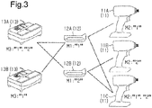
Fig. 3 is a diagram showing the compatibility of a power tool body and a battery pack and the compatibility of a charger and the battery pack in the power tool system of the embodiment. - One embodiment of a power tool system will now be described with reference to the drawings.
- As shown in
Fig. 1 , the power tool system includes apower tool 10 and acharger 13. Thepower tool 10 includes apower tool body 11 and abattery pack 12. Thecharger 13 charges thebattery pack 12. - As shown in
Fig. 2 , ahousing 14 that forms the shell of thepower tool body 11 includes atubular barrel 15 and ahandle 16 extending downwardly from thebarrel 15 at a middle portion with respect to a front-to-rear direction (longitudinal direction). Abattery pack seat 17, to which thebattery pack 12 is attached, is arranged at the lower side of thehandle 16. - The
barrel 15 of thehousing 14 includes amotor 20 and apower transmission unit 21, which includes a reduction drive driven by and coupled to themotor 20. Abit attaching portion 22 is connected to a distal end of thepower transmission unit 21. Various bits (not shown) are attached to thebit attaching portion 22. This allows thepower transmission unit 21 to transmit the rotation drive force of themotor 20 to the bits. - As shown in
Fig. 1 , thepower tool body 11 includes acontroller 23 that controls the rotation produced by themotor 20 and amemory 24 that stores various types of setting information. Thememory 24 stores, for example, identification information M2 of thebattery pack 12 that is compatible. The identification information M2 stored in thememory 24 includes identification information M1 of one ormore battery packs 12. For example, when thepower tool body 11 corresponds to only one type ofbattery pack 12, only one piece of identification information M1 is stored in advance in thememory 24 as the identification information M2. When thepower tool body 11 corresponds to multiple types ofbattery packs 12, multiple pieces of identification information M1 having different contents are stored in advance in thememory 24 as the identification information M2. - As shown in
Fig. 2 , thebattery pack 12 is configured so that it can be coupled (connected) to thebattery pack seat 17 of thepower tool body 11. - As shown in
Fig. 1 , thebattery pack 12 includes arechargeable battery 31 including one or more cells, acontroller 32 that controls charging and power supplying of therechargeable battery 31, and a memory 33 that stores various types of setting information. The memory 33 functions as a battery pack memory. - The identification information M1 is stored in advance in the memory 33 of the
battery pack 12. The identification information M1 is used to determine whether or not thebattery pack 12 is compatible with thepower tool body 11 or thecharger 13 when thebattery pack 12 is connected to thepower tool body 11 or thecharger 13. For example, the identification information M1 is stored in the smallest unit allowing for communication. The identification information M1 may have data size of the smallest unit (one nibble = four bits) when communication is established. This allows a maximum of sixteen types of identification information M1 to be set. The identification information M1 may include an identification number that identifies thebattery pack 12. - As shown in
Fig. 1 , thecharger 13 includes acharging unit 41 that charges therechargeable battery 31 of thebattery pack 12, acontroller 42 that controls thecharging unit 41, and amemory 43 that stores various types of setting information. - The
memory 43 of thecharger 13 stores, for example, identification information M3 of thebattery pack 12 that is compatible. The identification information M3 stored in thememory 43 includes the identification information M1 of one ormore battery packs 12. For example, when thecharger 13 only corresponds to one type ofbattery pack 12, only one piece of identification information M1 is stored in advance in thememory 24 as the identification information M3. When thecharger 13 corresponds to multiple types ofbattery packs 12, multiple pieces of identification information M1 having different contents are stored in advance in thememory 24 as the identification information M3. - The power tool system uses the identification information M1, the identification information M2, and the identification information M3 to determine whether or not the
power tool body 11 is compatible with thebattery pack 12 and thecharger 13 is compatible with thebattery pack 12. The compatibility determination of thepower tool body 11 and thebattery pack 12 and the compatibility determination of thecharger 13 and thebattery pack 12 will now be described mainly with reference toFigs. 1 and3 . The compatibility of the power tool system shown inFig. 3 will now be described using threepower tool bodies 11, twobattery packs 12, and twochargers 13. To facilitate understanding, the threepower tool bodies 11 are distinguished from one another as a power tool body 11 A, apower tool body 11B, and apower tool body 11C using different reference characters. In the same manner, to facilitate understanding, the twobattery packs 12 are distinguished from one another as abattery pack 12A and abattery pack 12B using different reference characters. Further, to facilitate understanding, the twochargers 13 are distinguished from one another as acharger 13A and acharger 13B using different reference characters. - As shown in
Fig. 3 , the power tool body 11 A stores only "1" as the identification information M2. Thepower tool body 11 B stores only "2" as the identification information M2. Thepower tool body 11C stores "1" and "2" as the identification information M2. - As shown in
Fig. 3 , thebattery pack 12A stores only "1" as the identification information M1. Thebattery pack 12B stores only "2" as the identification information M1. - As shown in
Fig. 3 , thecharger 13A stores "1" and "2" as the identification information M3. Thecharger 13B stores only "1" as the identification information M1. - As shown in
Figs. 1 and3 , when thebattery pack 12A is attached to the power tool body 11A, thecontroller 23 of the power tool body 11A reads the identification information M1 ("1"), which is set to thebattery pack 12A, from the memory 33 of thebattery pack 12A via thecontroller 32. Thecontroller 32 of the power tool body 11A compares the identification information M1 and the identification information M2 ("1"), which is stored in thememory 24 of the power tool body 11A, and determines whether or not the power tool body 11A is compatible with thebattery pack 12A. The identification information M1 set to thebattery pack 12A is "1," and the identification information M2 set to the power tool body 11A is "1." Thus, thecontroller 32 determines that the power tool body 11A is compatible with thebattery pack 12A. Accordingly, thecontroller 32 permits the supply of power from thebattery pack 12A to the power tool body 11A. - As shown in
Figs. 1 and3 , when thebattery pack 12B is attached to the power tool body 11A, thecontroller 23 of the power tool body 11A reads the identification information M1 ("2"), which is set to thebattery pack 12B, from the memory 33 of thebattery pack 12B via thecontroller 32. Thecontroller 32 of the power tool body 11 A compares the identification information M1 and the identification information M2 ("1 "), which is stored in thememory 24 of the power tool body 11A, and determines whether or not the power tool body 11A is compatible with thebattery pack 12B. The identification information M1 set to thebattery pack 12B is "2," and the identification information M2 set to the power tool body 11A is "1." Thus, thecontroller 32 determines that the power tool body 11 A is not compatible with thebattery pack 12B. Accordingly, thecontroller 32 is configured not to permit the supply of power from thebattery pack 12B to the power tool body 11 A. - As shown in
Figs. 1 and3 , when thebattery pack 12A is attached to thepower tool body 11 B, thecontroller 23 of thepower tool body 11 B reads the identification information M1 ("1"), which is set to thebattery pack 12A, from the memory 33 of thebattery pack 12A via thecontroller 32. Thecontroller 32 of thepower tool body 11 B compares the identification information M1 and the identification information M2 ("2"), which is stored in thememory 24 of thepower tool body 11 B, and determines whether or not thepower tool body 11 B is compatible with thebattery pack 12A. The identification information M1 set to thebattery pack 12A is "1," and the identification information M2 set to thepower tool body 11 B is "2." Thus, thecontroller 32 determines that the power tool body 11A is not compatible with thebattery pack 12A. Accordingly, thecontroller 32 is configured not to permit the supply of power from thebattery pack 12A to thepower tool body 11 B. - As shown in
Figs. 1 and3 , when thebattery pack 12B is attached to thepower tool body 11 B, thecontroller 23 of thepower tool body 11 B reads the identification information M1 ("2"), which is set to thebattery pack 12B, from the memory 33 of thebattery pack 12B via thecontroller 32. Thecontroller 32 of thepower tool body 11B compares the identification information M1 and the identification information M2 ("2"), which is stored in thememory 24 of thepower tool body 11 B, and determines whether or not thepower tool body 11 B is compatible with thebattery pack 12B. The identification information M1 set to thebattery pack 12B is "2," and the identification information M2 set to thepower tool body 11 B is "2." Thus, thecontroller 32 determines that thepower tool body 11B is compatible with thebattery pack 12B. Accordingly, thecontroller 32 permits the supply of power from thebattery pack 12B to thepower tool body 11 B. - As shown in
Figs. 1 and3 , when thebattery pack 12A is attached to thepower tool body 11C, thecontroller 23 of thepower tool body 11C reads the identification information M1 ("1"), which is set to thebattery pack 12A, from the memory 33 of thebattery pack 12A via thecontroller 32. Thecontroller 32 of thepower tool body 11C compares the identification information M1 and the identification information M2 ("1" and "2"), which is stored in thememory 24 of thepower tool body 11C, and determines whether or not thepower tool body 11C is compatible with thebattery pack 12A. The identification information M1 set to thebattery pack 12A is "1," and the identification information M2 set to thepower tool body 11C is "1" and "2." That is, since the identification information M2 includes the identification information M1, thecontroller 32 determines that thepower tool body 11C is compatible with thebattery pack 12A. Accordingly, thecontroller 32 permits the supply of power from thebattery pack 12A to thepower tool body 11C. - As shown in
Figs. 1 and3 , when thebattery pack 12B is attached to thepower tool body 11C, thecontroller 23 of thepower tool body 11C reads the identification information M1 ("2"), which is set to thebattery pack 12B, from the memory 33 of thebattery pack 12B via thecontroller 32. Thecontroller 32 of thepower tool body 11C compares the identification information M1 and the identification information M2 ("1" and "2"), which is stored in thememory 24 of thepower tool body 11C, and determines whether or not thepower tool body 11C is compatible with thebattery pack 12B. The identification information M1 set to thebattery pack 12B is "2," and the identification information M2 set to thepower tool body 11C is "1" and "2." That is, since the identification information M2 includes the identification information M1, thecontroller 32 determines that thepower tool body 11C is compatible with thebattery pack 12B. Accordingly, thecontroller 32 permits the supply of power from thebattery pack 12B to thepower tool body 11C. - As shown in
Figs. 1 and3 , when thebattery pack 12A is attached to thecharger 13A, thecontroller 42 of thecharger 13A reads the identification information M1 ("1 "), which is set to thebattery pack 12A, from the memory 33 of thebattery pack 12A via thecontroller 32. Thecontroller 42 of thecharger 13A compares the identification information M1 and the identification information M3 ("1" and "2"), which is stored in thememory 43 of thecharger 13A, and determines whether or not thecharger 13A is compatible with thebattery pack 12A. The identification information M1 set to thebattery pack 12A is "1," and the identification information M3 set to thecharger 13A is "1" and "2." That is, the identification information M3 includes the identification information M1. Thus, thecontroller 42 determines that thecharger 13A is compatible with thebattery pack 12A. Accordingly, thecontroller 42 permits charging from thecharger 13A to thebattery pack 12A. - As shown in
Figs. 1 and3 , when thebattery pack 12B is attached to thecharger 13A, thecontroller 42 of thecharger 13A reads the identification information M1 ("2"), which is set to thebattery pack 12B, from the memory 33 of thebattery pack 12B via thecontroller 32. Thecontroller 42 of thecharger 13A compares the identification information M1 and the identification information M3 ("1" and "2"), which is stored in thememory 43 of thecharger 13A, and determines whether or not thecharger 13A is compatible with thebattery pack 12B. The identification information M1 set to thebattery pack 12B is "1," and the identification information M3 set to thecharger 13A is "1" and "2." That is, the identification information M3 includes the identification information M1. Thus, thecontroller 42 determines that thecharger 13A is compatible with thebattery pack 12B. Accordingly, thecontroller 42 permits charging from thecharger 13A to thebattery pack 12B. - As shown in
Figs. 1 and3 , when thebattery pack 12A is attached to thecharger 13B, thecontroller 42 of thecharger 13B reads the identification information M1 ("1"), which is set to thebattery pack 12A, from the memory 33 of thebattery pack 12A via thecontroller 32. Thecontroller 42 of thecharger 13B compares the identification information M1 and the identification information M3 ("1" and "2"), which is stored in thememory 43 of thecharger 13B, and determines whether or not thecharger 13B is compatible with thebattery pack 12A. The identification information M1 set to thebattery pack 12A is "1," and the identification information M3 set to thecharger 13B is "1." Thus, thecontroller 42 determines that thecharger 13B is compatible with thebattery pack 12A. Accordingly, thecontroller 42 permits charging from thecharger 13B to thebattery pack 12A. - As shown in
Figs. 1 and3 , when thebattery pack 12B is attached to thecharger 13B, thecontroller 42 of thecharger 13B reads the identification information M1 ("2"), which is set to thebattery pack 12B, from the memory 33 of thebattery pack 12B via thecontroller 32. Thecontroller 42 of thecharger 13B compares the identification information M1 and the identification information M3 ("1 "), which is stored in thememory 43 of thecharger 13B, and determines whether or not thecharger 13B is compatible with thebattery pack 12B. The identification information M1 set to thebattery pack 12B is "2," and the identification information M3 set to thecharger 13B is "1." Thus, thecontroller 42 determines that thecharger 13B is not compatible with thebattery pack 12B. Accordingly, thecontroller 42 is configured not to permit charging from thecharger 13B to thebattery pack 12B. - The present embodiment has the advantages described below.
- (1) The
battery pack 12 includes the memory 33 that stores the identification information M1 in the smallest unit in which communication can be established with thepower tool body 11 and thecharger 13, and thepower tool body 11 and thecharger 13 respectively include thememories usable battery pack 12 in advance. Thepower tool body 11 and thecharger 13 respectively include thecontrollers memories battery pack 12 and thepower tool body 11 and the compatibility of thebattery pack 12 and thecharger 13. This minimizes the data required to perform compatibility determination and allows for quicker compatibility determination. - (2) The
charger 13 includes thecontroller 42 functioning as a charging permission unit that permits charging of thebattery pack 12 when determining that the identification information M1 stored in the memory 33 corresponds to the identification information M3 stored in thememory 43. After checking the compatibility of thebattery pack 12 and thecharger 13 in this manner, charging is quickly permitted to quickly start charging. As a result, charging can be completed quickly. - (3) The
power tool body 11 includes thecontroller 23 functioning as a power supplying permission unit that permits the supply of power to thepower tool body 11 when determining that the identification information M1 stored in the memory 33 corresponds to the identification information M2 stored in thememory 24 of thepower tool body 11. After checking the compatibility of thebattery pack 12 and thepower tool body 11 in this manner, the supply of power is quickly permitted to quickly start the supply of power to themotor 20. This allows a user to quickly start a task. - The above embodiment may be modified as described below.
- In the above embodiment, the
controller 42 of thecharger 13 functions as a charging permission unit. Instead, thecontroller 32 of thecharger 13 may function as a charging permission unit. - In the above embodiment, the
controller 23 of thepower tool body 11 functions as a power supplying permission unit. Instead, thecontroller 32 of thepower tool body 11 may function as a power supplying permission unit. - In the above embodiment, the
controller 23 of thepower tool body 11 functions as a determination unit that determines the compatibility of thepower tool body 11 and thebattery pack 12. Instead, thecontroller 32 of thebattery pack 12 may function as a determination unit that determines the compatibility of thepower tool body 11 and thebattery pack 12. - In the above embodiment, the
controller 42 of thecharger 13 functions as a determination unit that determines the compatibility of thecharger 13 and thebattery pack 12. Instead, thecontroller 32 of thebattery pack 12 may function as a determination unit that determines the compatibility of thecharger 13 and thebattery pack 12. - Although not particularly mentioned in the above embodiment, when the battery pack to which the identification information M1 is set is attached to a conventional power tool body to which the identification information M2 is not set and a conventional charger to which the identification information M3 is not set, the power tool body and the charger cannot identify the battery pack. In this case, the conventional power tool body and the conventional charger are configured so as not to charge the battery pack and not to supply power from the battery pack.
- Further, when a conventional battery pack to which the identification information M1 is not set is attached to the power tool body to which the identification information M2 is set and the charger to which the identification information M3 is set, the power tool body or the charger cannot identify the battery pack. The power tool body to which the identification information M2 is set and the charger to which the identification information M3 is set may be configured so as not to charge the battery pack and not to supply power from the battery pack.
- The embodiment and each of the modified examples may be combined.
- The technical concept that can be understood from the embodiment and the modified examples will now be described.
- A power tool system includes a battery pack (12), a charger (13) connectable to the battery pack, and a power tool body (11) connectable to the battery pack (12). The battery pack includes a battery pack memory (33) that stores identification information in a smallest unit allowing for communication with the charger (13) and the power tool body (11). Each of the charger (13) and the power tool body (11) includes a device memory (24, 43) that stores identification information of at least one usable battery pack. Each of the charger (13) and the power tool body (11) or the battery pack (12) includes a determination unit (23, 32, 42) that determines whether or not the at least one piece of identification information stored in the device memory (24, 43) includes the identification information stored in the battery pack memory (33).
- In the power tool system according to
embodiment 1, the charger (13) includes a power supplying permission unit (42) that permits charging of the power tool body (12) when the determination unit (32, 42) determines that the at least one piece of identification information stored in the device memory (43) of the charger (13) includes the identification information stored in the battery pack memory (33). - In the power tool system according to
embodiment 1, the battery pack (12) includes a charging permission unit (32) that permits charging of the battery pack (12) when the determination unit (32, 42) determines that the at least one piece of identification information stored in the device memory (43) of the charger (13) includes the identification information stored in the battery pack memory (33). - In the power tool system according to any one of
embodiments 1 to 3, the power tool body (11) includes a power supplying permission unit (23) that permits the power tool body (11) to be supplied when the determination unit (23) determines that the at least one piece of identification information stored in the device memory (24) of the power tool body (11) includes the identification information stored in the battery pack memory (33). - In the power tool system according to any one of
embodiments 1 to 3, the battery pack (12) includes a power supplying permission unit (32) that permits the power tool body (11) to be supplied with power when the determination unit (23) determines that the at least one piece of identification information stored in the device memory (24) of the power tool body (11) includes the identification information stored in the battery pack memory (33).
Claims (5)
- A power tool system comprising:a battery pack;a charger connectable to the battery pack; anda power tool body connectable to the battery pack, whereinthe battery pack includes a battery pack memory that stores identification information in a smallest unit allowing for communication with the charger and the power tool body,each of the charger and the power tool body includes a device memory that stores at least one piece of identification information of a usable battery pack, andeach of the charger and the power tool body or the battery pack includes a determination unit that determines whether or not the at least one piece of identification information stored in the device memory includes the identification information stored in the battery pack memory.
- The power tool system according to claim 1, wherein the charger includes a charging permission unit that permits charging of the battery pack when the determination unit determines that the at least one piece of identification information stored in the device memory of the charger includes the identification information stored in the battery pack memory.
- The power tool system according to claim 1, wherein the battery pack includes a charging permission unit that permits charging of the battery pack when the determination unit determines that the at least one piece of identification information stored in the device memory of the charger includes the identification information stored in the battery pack memory.
- The power tool system according to any one of claims 1 to 3, wherein the power tool body includes a power supplying permission unit that permits the power tool body to be supplied with power when the determination unit determines that the at least one piece of identification information stored in the device memory of the power tool body includes the identification information stored in the battery pack memory.
- The power tool system according to any one of claims 1 to 3, wherein the battery pack includes a power supplying permission unit that permits the power tool body to be supplied with power when the determination unit determines that the at least one piece of identification information stored in the device memory of the power tool body includes the identification information stored in the battery pack memory.
Applications Claiming Priority (2)
| Application Number | Priority Date | Filing Date | Title |
|---|---|---|---|
| JP2015048315A JP2016168634A (en) | 2015-03-11 | 2015-03-11 | Electric tool system |
| PCT/JP2016/001214 WO2016143321A1 (en) | 2015-03-11 | 2016-03-04 | Electric tool system |
Publications (2)
| Publication Number | Publication Date |
|---|---|
| EP3269515A4 EP3269515A4 (en) | 2018-01-17 |
| EP3269515A1 true EP3269515A1 (en) | 2018-01-17 |
Family
ID=56879424
Family Applications (1)
| Application Number | Title | Priority Date | Filing Date |
|---|---|---|---|
| EP16761295.1A Pending EP3269515A1 (en) | 2015-03-11 | 2016-03-04 | Electric tool system |
Country Status (5)
| Country | Link |
|---|---|
| US (1) | US10263543B2 (en) |
| EP (1) | EP3269515A1 (en) |
| JP (1) | JP2016168634A (en) |
| CN (1) | CN107405765B (en) |
| WO (1) | WO2016143321A1 (en) |
Cited By (3)
| Publication number | Priority date | Publication date | Assignee | Title |
|---|---|---|---|---|
| US11569765B2 (en) | 2019-10-11 | 2023-01-31 | Black & Decker Inc. | Power tool receiving different capacity battery packs |
| EP4559628A1 (en) * | 2023-11-21 | 2025-05-28 | Hilti Aktiengesellschaft | Power tool system and authorization method |
| EP4570438A1 (en) * | 2023-12-14 | 2025-06-18 | Hilti Aktiengesellschaft | Power tool system, asset management system and method for regulating the collaboration of power tools |
Families Citing this family (10)
| Publication number | Priority date | Publication date | Assignee | Title |
|---|---|---|---|---|
| CN110071534A (en) * | 2018-07-24 | 2019-07-30 | 苏州德昊智能科技有限公司 | With anti-fraud functional electric tool charge-discharge system and method |
| CN110416642B (en) * | 2019-07-30 | 2022-05-31 | 四川长虹电器股份有限公司 | Brand protection system with disposable replaceable battery |
| EP3800722A1 (en) * | 2019-10-01 | 2021-04-07 | Hilti Aktiengesellschaft | Method for efficiently discharging an accumulator |
| EP4074462B1 (en) * | 2019-12-13 | 2026-05-06 | Positec Power Tools (Suzhou) Co., Ltd | Control device and electric power tool system |
| JP7550536B2 (en) * | 2020-05-28 | 2024-09-13 | キヤノン株式会社 | Electronic device, control method, and program |
| JP7564644B2 (en) * | 2020-05-28 | 2024-10-09 | キヤノン株式会社 | Electronic device, control method, and program |
| CN114362342B (en) * | 2020-09-30 | 2024-03-15 | 南京泉峰科技有限公司 | Power tool systems and battery packs |
| EP4191817A1 (en) * | 2021-12-01 | 2023-06-07 | Hilti Aktiengesellschaft | Charging control by means of a battery |
| JP2023150599A (en) * | 2022-03-31 | 2023-10-16 | 株式会社マキタ | Electric working machine systems, battery packs and electric working machines |
| DE112024002726T5 (en) * | 2023-06-28 | 2026-04-09 | Milwaukee Electric Tool Corporation | Distributed and networked charging of power tool batteries with user-defined settings |
Family Cites Families (13)
| Publication number | Priority date | Publication date | Assignee | Title |
|---|---|---|---|---|
| US6119074A (en) * | 1998-05-20 | 2000-09-12 | Caterpillar Inc. | Method and apparatus of predicting a fault condition |
| US6018227A (en) * | 1998-06-22 | 2000-01-25 | Stryker Corporation | Battery charger especially useful with sterilizable, rechargeable battery packs |
| JP4212333B2 (en) * | 2002-10-29 | 2009-01-21 | 三洋電機株式会社 | Batteries, equipment, and chargers |
| EP1805863B1 (en) | 2004-10-18 | 2013-06-26 | Black & Decker, Inc. | Cordless power system |
| AU2012202583B2 (en) * | 2005-10-21 | 2015-04-09 | Stryker Corporation | Battery charger |
| EP1780867B1 (en) | 2005-10-28 | 2016-11-30 | Black & Decker Inc. | Battery pack for cordless power tools |
| US8294403B2 (en) * | 2009-09-04 | 2012-10-23 | Haas Automation, Inc. | Methods and systems for determining and displaying a time to overload of machine tools |
| JP2011135740A (en) * | 2009-12-25 | 2011-07-07 | Makita Corp | Battery pack for power tool and battery connection device |
| JP5288563B2 (en) | 2010-03-26 | 2013-09-11 | パナソニック株式会社 | Electric tool |
| JP2012104039A (en) | 2010-11-12 | 2012-05-31 | Sony Corp | Electronic apparatus, battery pack, communication system, and communication method |
| EP2734340B1 (en) * | 2011-07-24 | 2017-12-20 | Makita Corporation | Theft-deterrence system for power tool system, and adapter and method therefor |
| JP6074708B2 (en) | 2013-03-12 | 2017-02-08 | パナソニックIpマネジメント株式会社 | Electric tool |
| CN103595094A (en) * | 2013-10-31 | 2014-02-19 | 徐州市恒源电器有限公司 | Electric tool wireless charging device |
-
2015
- 2015-03-11 JP JP2015048315A patent/JP2016168634A/en active Pending
-
2016
- 2016-03-04 US US15/554,995 patent/US10263543B2/en active Active
- 2016-03-04 CN CN201680014063.XA patent/CN107405765B/en active Active
- 2016-03-04 WO PCT/JP2016/001214 patent/WO2016143321A1/en not_active Ceased
- 2016-03-04 EP EP16761295.1A patent/EP3269515A1/en active Pending
Cited By (3)
| Publication number | Priority date | Publication date | Assignee | Title |
|---|---|---|---|---|
| US11569765B2 (en) | 2019-10-11 | 2023-01-31 | Black & Decker Inc. | Power tool receiving different capacity battery packs |
| EP4559628A1 (en) * | 2023-11-21 | 2025-05-28 | Hilti Aktiengesellschaft | Power tool system and authorization method |
| EP4570438A1 (en) * | 2023-12-14 | 2025-06-18 | Hilti Aktiengesellschaft | Power tool system, asset management system and method for regulating the collaboration of power tools |
Also Published As
| Publication number | Publication date |
|---|---|
| JP2016168634A (en) | 2016-09-23 |
| WO2016143321A1 (en) | 2016-09-15 |
| US20180048249A1 (en) | 2018-02-15 |
| EP3269515A4 (en) | 2018-01-17 |
| CN107405765A (en) | 2017-11-28 |
| US10263543B2 (en) | 2019-04-16 |
| CN107405765B (en) | 2021-01-12 |
Similar Documents
| Publication | Publication Date | Title |
|---|---|---|
| EP3269515A1 (en) | Electric tool system | |
| JP6982528B2 (en) | Battery packs and chargers, and battery pack kits for power tools | |
| US7453171B2 (en) | DC power source determination circuitry for use with an adapter | |
| EP2518857B1 (en) | Battery pack for electric tool, and battery connection device | |
| EP2963765B1 (en) | Power tool charging device and power tool charging system | |
| US20180175648A1 (en) | Configurable rechargeable battery pack | |
| JP2012124997A (en) | Charger, adapter, and charge system | |
| CN108886264A (en) | Unit balance method and system | |
| DE102011005646A1 (en) | Mobile charger | |
| CN101189564A (en) | Method and apparatus for charging a power source | |
| EP1616382B1 (en) | Power supply system for a vehicle | |
| JP2016208832A (en) | Battery control apparatus, battery module, battery pack, and battery control method | |
| EP4012429B1 (en) | Method of estimating a state-of-charge of a battery pack | |
| CN108702020A (en) | Portable unmanned machine battery charging system | |
| US11114868B2 (en) | Supplemental capacitor based battery charging system | |
| JP6818060B2 (en) | Device and method | |
| EP2521206A1 (en) | Portable apparatus for powering and controlling electrical equipment, particularly for agricultural use | |
| US20150048780A1 (en) | Charging device | |
| EP3214722A1 (en) | Charging device | |
| JP2011097681A (en) | Power supply system of electric device | |
| US20210273482A1 (en) | Auxiliary energy circuit for battery-powered power tool | |
| DE102021101682A1 (en) | Configurable battery pack, battery-powered device, external charger, and method of configuring a battery pack | |
| US20130119791A1 (en) | Electric power tool | |
| EP4009478B1 (en) | Configurable battery pack, battery-operated device, external charging device and battery pack configuration method | |
| DE102016201407A1 (en) | Device for operating a mobile electrical energy storage and energy storage system |
Legal Events
| Date | Code | Title | Description |
|---|---|---|---|
| STAA | Information on the status of an ep patent application or granted ep patent |
Free format text: STATUS: THE INTERNATIONAL PUBLICATION HAS BEEN MADE |
|
| PUAI | Public reference made under article 153(3) epc to a published international application that has entered the european phase |
Free format text: ORIGINAL CODE: 0009012 |
|
| STAA | Information on the status of an ep patent application or granted ep patent |
Free format text: STATUS: REQUEST FOR EXAMINATION WAS MADE |
|
| 17P | Request for examination filed |
Effective date: 20170908 |
|
| A4 | Supplementary search report drawn up and despatched |
Effective date: 20171208 |
|
| AK | Designated contracting states |
Kind code of ref document: A1 Designated state(s): AL AT BE BG CH CY CZ DE DK EE ES FI FR GB GR HR HU IE IS IT LI LT LU LV MC MK MT NL NO PL PT RO RS SE SI SK SM TR |
|
| AX | Request for extension of the european patent |
Extension state: BA ME |
|
| DAV | Request for validation of the european patent (deleted) | ||
| DAX | Request for extension of the european patent (deleted) | ||
| STAA | Information on the status of an ep patent application or granted ep patent |
Free format text: STATUS: EXAMINATION IS IN PROGRESS |
|
| 17Q | First examination report despatched |
Effective date: 20210408 |