EP3269329A1 - Venous valve prostheses - Google Patents
Venous valve prostheses Download PDFInfo
- Publication number
- EP3269329A1 EP3269329A1 EP17180531.0A EP17180531A EP3269329A1 EP 3269329 A1 EP3269329 A1 EP 3269329A1 EP 17180531 A EP17180531 A EP 17180531A EP 3269329 A1 EP3269329 A1 EP 3269329A1
- Authority
- EP
- European Patent Office
- Prior art keywords
- valve body
- frame
- valve
- lumen
- medical device
- Prior art date
- Legal status (The legal status is an assumption and is not a legal conclusion. Google has not performed a legal analysis and makes no representation as to the accuracy of the status listed.)
- Granted
Links
Images





Classifications
-
- A—HUMAN NECESSITIES
- A61—MEDICAL OR VETERINARY SCIENCE; HYGIENE
- A61F—FILTERS IMPLANTABLE INTO BLOOD VESSELS; PROSTHESES; DEVICES PROVIDING PATENCY TO, OR PREVENTING COLLAPSING OF, TUBULAR STRUCTURES OF THE BODY, e.g. STENTS; ORTHOPAEDIC, NURSING OR CONTRACEPTIVE DEVICES; FOMENTATION; TREATMENT OR PROTECTION OF EYES OR EARS; BANDAGES, DRESSINGS OR ABSORBENT PADS; FIRST-AID KITS
- A61F2/00—Filters implantable into blood vessels; Prostheses, i.e. artificial substitutes or replacements for parts of the body; Appliances for connecting them with the body; Devices providing patency to, or preventing collapsing of, tubular structures of the body, e.g. stents
- A61F2/02—Prostheses implantable into the body
- A61F2/24—Heart valves ; Vascular valves, e.g. venous valves; Heart implants, e.g. passive devices for improving the function of the native valve or the heart muscle; Transmyocardial revascularisation [TMR] devices; Valves implantable in the body
- A61F2/2475—Venous valves
-
- A—HUMAN NECESSITIES
- A61—MEDICAL OR VETERINARY SCIENCE; HYGIENE
- A61F—FILTERS IMPLANTABLE INTO BLOOD VESSELS; PROSTHESES; DEVICES PROVIDING PATENCY TO, OR PREVENTING COLLAPSING OF, TUBULAR STRUCTURES OF THE BODY, e.g. STENTS; ORTHOPAEDIC, NURSING OR CONTRACEPTIVE DEVICES; FOMENTATION; TREATMENT OR PROTECTION OF EYES OR EARS; BANDAGES, DRESSINGS OR ABSORBENT PADS; FIRST-AID KITS
- A61F2/00—Filters implantable into blood vessels; Prostheses, i.e. artificial substitutes or replacements for parts of the body; Appliances for connecting them with the body; Devices providing patency to, or preventing collapsing of, tubular structures of the body, e.g. stents
- A61F2/02—Prostheses implantable into the body
- A61F2/24—Heart valves ; Vascular valves, e.g. venous valves; Heart implants, e.g. passive devices for improving the function of the native valve or the heart muscle; Transmyocardial revascularisation [TMR] devices; Valves implantable in the body
- A61F2/2427—Devices for manipulating or deploying heart valves during implantation
- A61F2/2436—Deployment by retracting a sheath
-
- A—HUMAN NECESSITIES
- A61—MEDICAL OR VETERINARY SCIENCE; HYGIENE
- A61F—FILTERS IMPLANTABLE INTO BLOOD VESSELS; PROSTHESES; DEVICES PROVIDING PATENCY TO, OR PREVENTING COLLAPSING OF, TUBULAR STRUCTURES OF THE BODY, e.g. STENTS; ORTHOPAEDIC, NURSING OR CONTRACEPTIVE DEVICES; FOMENTATION; TREATMENT OR PROTECTION OF EYES OR EARS; BANDAGES, DRESSINGS OR ABSORBENT PADS; FIRST-AID KITS
- A61F2/00—Filters implantable into blood vessels; Prostheses, i.e. artificial substitutes or replacements for parts of the body; Appliances for connecting them with the body; Devices providing patency to, or preventing collapsing of, tubular structures of the body, e.g. stents
- A61F2/82—Devices providing patency to, or preventing collapsing of, tubular structures of the body, e.g. stents
- A61F2/844—Devices providing patency to, or preventing collapsing of, tubular structures of the body, e.g. stents folded prior to deployment
-
- A—HUMAN NECESSITIES
- A61—MEDICAL OR VETERINARY SCIENCE; HYGIENE
- A61F—FILTERS IMPLANTABLE INTO BLOOD VESSELS; PROSTHESES; DEVICES PROVIDING PATENCY TO, OR PREVENTING COLLAPSING OF, TUBULAR STRUCTURES OF THE BODY, e.g. STENTS; ORTHOPAEDIC, NURSING OR CONTRACEPTIVE DEVICES; FOMENTATION; TREATMENT OR PROTECTION OF EYES OR EARS; BANDAGES, DRESSINGS OR ABSORBENT PADS; FIRST-AID KITS
- A61F2/00—Filters implantable into blood vessels; Prostheses, i.e. artificial substitutes or replacements for parts of the body; Appliances for connecting them with the body; Devices providing patency to, or preventing collapsing of, tubular structures of the body, e.g. stents
- A61F2/82—Devices providing patency to, or preventing collapsing of, tubular structures of the body, e.g. stents
- A61F2/86—Stents in a form characterised by the wire-like elements; Stents in the form characterised by a net-like or mesh-like structure
- A61F2/90—Stents in a form characterised by the wire-like elements; Stents in the form characterised by a net-like or mesh-like structure characterised by a net-like or mesh-like structure
-
- A—HUMAN NECESSITIES
- A61—MEDICAL OR VETERINARY SCIENCE; HYGIENE
- A61F—FILTERS IMPLANTABLE INTO BLOOD VESSELS; PROSTHESES; DEVICES PROVIDING PATENCY TO, OR PREVENTING COLLAPSING OF, TUBULAR STRUCTURES OF THE BODY, e.g. STENTS; ORTHOPAEDIC, NURSING OR CONTRACEPTIVE DEVICES; FOMENTATION; TREATMENT OR PROTECTION OF EYES OR EARS; BANDAGES, DRESSINGS OR ABSORBENT PADS; FIRST-AID KITS
- A61F2210/00—Particular material properties of prostheses classified in groups A61F2/00 - A61F2/26 or A61F2/82 or A61F9/00 or A61F11/00 or subgroups thereof
- A61F2210/0014—Particular material properties of prostheses classified in groups A61F2/00 - A61F2/26 or A61F2/82 or A61F9/00 or A61F11/00 or subgroups thereof using shape memory or superelastic materials, e.g. nitinol
-
- A—HUMAN NECESSITIES
- A61—MEDICAL OR VETERINARY SCIENCE; HYGIENE
- A61F—FILTERS IMPLANTABLE INTO BLOOD VESSELS; PROSTHESES; DEVICES PROVIDING PATENCY TO, OR PREVENTING COLLAPSING OF, TUBULAR STRUCTURES OF THE BODY, e.g. STENTS; ORTHOPAEDIC, NURSING OR CONTRACEPTIVE DEVICES; FOMENTATION; TREATMENT OR PROTECTION OF EYES OR EARS; BANDAGES, DRESSINGS OR ABSORBENT PADS; FIRST-AID KITS
- A61F2230/00—Geometry of prostheses classified in groups A61F2/00 - A61F2/26 or A61F2/82 or A61F9/00 or A61F11/00 or subgroups thereof
- A61F2230/0002—Two-dimensional shapes, e.g. cross-sections
- A61F2230/0004—Rounded shapes, e.g. with rounded corners
- A61F2230/0006—Rounded shapes, e.g. with rounded corners circular
-
- A—HUMAN NECESSITIES
- A61—MEDICAL OR VETERINARY SCIENCE; HYGIENE
- A61F—FILTERS IMPLANTABLE INTO BLOOD VESSELS; PROSTHESES; DEVICES PROVIDING PATENCY TO, OR PREVENTING COLLAPSING OF, TUBULAR STRUCTURES OF THE BODY, e.g. STENTS; ORTHOPAEDIC, NURSING OR CONTRACEPTIVE DEVICES; FOMENTATION; TREATMENT OR PROTECTION OF EYES OR EARS; BANDAGES, DRESSINGS OR ABSORBENT PADS; FIRST-AID KITS
- A61F2230/00—Geometry of prostheses classified in groups A61F2/00 - A61F2/26 or A61F2/82 or A61F9/00 or A61F11/00 or subgroups thereof
- A61F2230/0002—Two-dimensional shapes, e.g. cross-sections
- A61F2230/0004—Rounded shapes, e.g. with rounded corners
- A61F2230/0008—Rounded shapes, e.g. with rounded corners elliptical or oval
-
- A—HUMAN NECESSITIES
- A61—MEDICAL OR VETERINARY SCIENCE; HYGIENE
- A61F—FILTERS IMPLANTABLE INTO BLOOD VESSELS; PROSTHESES; DEVICES PROVIDING PATENCY TO, OR PREVENTING COLLAPSING OF, TUBULAR STRUCTURES OF THE BODY, e.g. STENTS; ORTHOPAEDIC, NURSING OR CONTRACEPTIVE DEVICES; FOMENTATION; TREATMENT OR PROTECTION OF EYES OR EARS; BANDAGES, DRESSINGS OR ABSORBENT PADS; FIRST-AID KITS
- A61F2250/00—Special features of prostheses classified in groups A61F2/00 - A61F2/26 or A61F2/82 or A61F9/00 or A61F11/00 or subgroups thereof
- A61F2250/0014—Special features of prostheses classified in groups A61F2/00 - A61F2/26 or A61F2/82 or A61F9/00 or A61F11/00 or subgroups thereof having different values of a given property or geometrical feature, e.g. mechanical property or material property, at different locations within the same prosthesis
- A61F2250/0036—Special features of prostheses classified in groups A61F2/00 - A61F2/26 or A61F2/82 or A61F9/00 or A61F11/00 or subgroups thereof having different values of a given property or geometrical feature, e.g. mechanical property or material property, at different locations within the same prosthesis differing in thickness
-
- A—HUMAN NECESSITIES
- A61—MEDICAL OR VETERINARY SCIENCE; HYGIENE
- A61F—FILTERS IMPLANTABLE INTO BLOOD VESSELS; PROSTHESES; DEVICES PROVIDING PATENCY TO, OR PREVENTING COLLAPSING OF, TUBULAR STRUCTURES OF THE BODY, e.g. STENTS; ORTHOPAEDIC, NURSING OR CONTRACEPTIVE DEVICES; FOMENTATION; TREATMENT OR PROTECTION OF EYES OR EARS; BANDAGES, DRESSINGS OR ABSORBENT PADS; FIRST-AID KITS
- A61F2250/00—Special features of prostheses classified in groups A61F2/00 - A61F2/26 or A61F2/82 or A61F9/00 or A61F11/00 or subgroups thereof
- A61F2250/0014—Special features of prostheses classified in groups A61F2/00 - A61F2/26 or A61F2/82 or A61F9/00 or A61F11/00 or subgroups thereof having different values of a given property or geometrical feature, e.g. mechanical property or material property, at different locations within the same prosthesis
- A61F2250/0039—Special features of prostheses classified in groups A61F2/00 - A61F2/26 or A61F2/82 or A61F9/00 or A61F11/00 or subgroups thereof having different values of a given property or geometrical feature, e.g. mechanical property or material property, at different locations within the same prosthesis differing in diameter
Definitions
- This disclosure relates to an implantable medical device, and more specifically to venous valve prostheses.
- Venous valves are found within the vasculature of a mammal, particularly the veins. Venous valves prevent the backflow of blood during circulation. For example, venous valves help to fight backflow of blood in the legs caused by gravity pulling the blood away from the heart and back towards the feet of a person when standing. However, when venous valves fail to work properly, blood can flow backwards within the veins and pool in, for example, the legs. Such pooling of blood can cause the veins to become distended, thereby causing the venous valves to fail further. This progressively worsening disorder can lead to varicose veins and chronic venous insufficiency, which is painful and can lead to lower limb ulcerations.
- Native venous valves are valves created by thin, overlapping leaflets of tissue that open in response to antegrade pressure, but close in response to retrograde pressure. These valves may be reconstructed in a surgical procedure, but are complicated to reconstruct.
- Known prosthetic venous valves that attempt to replicate the function of the native leaflet design are complicated to fabricate, may require extensive invasive surgery to implant, may be damaged if implanted by percutaneous delivery, and tend to form thrombosis soon after implementation.
- each implantable medical device may include a frame defining a frame lumen and a valve body defining a valve lumen.
- the valve body may be connected to the frame such that the valve lumen is in fluid communication with the frame lumen.
- the frame may be expandable such that it may expand when deployed to a treatment area such that it may anchor the valve body within the treatment area which may be, for example, an area of a vein comprising a native venous valve.
- the valve body may comprise a neck and may be configured to fold about the neck to at least partially close the valve lumen in an absence of fluid flow through the valve lumen or in the presence of retrograde fluid flow, and to open in the presence of antegrade fluid flow through the valve lumen.
- the valve body may be further configured to collapse in the absence of fluid flow through the valve lumen to at least partially close the valve lumen.
- the implantable medical device may be delivered to a treatment site via a delivery catheter.
- a distal portion of the delivery catheter may be advanced to the treatment site and the implantable medical device may be deployed from the delivery catheter to the treatment site.
- the treatment site may be an area of a vein, such as a vein within a leg of a patient, comprising a venous valve.
- the present disclosure describes an implantable medical device comprising a frame and a flexible tubular valve body.
- the frame defines a frame lumen and is expandable from a compressed configuration to an expanded configuration.
- the flexible tubular valve body extends between a downstream end and an upstream end.
- the valve body defines a valve lumen, a downstream opening at the downstream end, and an upstream opening at the upstream end.
- the valve body is attached to the frame such that the frame lumen is in fluid communication with the valve lumen.
- the valve body comprises a neck and is configured to fold about the neck to at least partially close the valve lumen in an absence of fluid flow through the valve lumen or in the presence of retrograde fluid flow, and the valve body is configured to open in the presence of antegrade fluid flow through the valve lumen. In some embodiments, the valve body is further configured to collapse in an absence of fluid flow through the valve lumen to at least partially close the valve lumen.
- the downstream opening is smaller than the upstream opening.
- the downstream opening is circular. In certain other embodiments, the downstream opening is oval.
- a downstream portion of the valve body defines at least one crease such that the valve body is configured to preferentially fold along the crease to at least partially close the valve lumen.
- the valve lumen decreases in diameter as it extends away from the frame.
- a thickness of a material forming the valve body is smaller at the neck than at least at one other portion of the valve body.
- the frame comprises steel. In certain other embodiments, the frame comprises nitinol.
- the frame defines a coil. In some other embodiments, the frame defines a latticed structure. In still other embodiments, the frame defines an open ring. In certain other embodiments, the frame defines a closed ring. In various embodiments, the frame may be a combination of these configurations.
- valve body defines a ribbed exterior surface. In some other embodiments, the valve body defines a substantially smooth exterior surface.
- the valve body comprises at least one of a polymer or a fluoropolymer.
- the size of the downstream opening is approximately 50%-90% the size of the upstream opening.
- the present disclosure describes a method comprising advancing a distal end of a catheter to a treatment site within a patient.
- An implantable medical device is disposed within the catheter. The method further comprises releasing the implantable medical device from the catheter at the treatment site.
- the implantable medical device comprises a frame and a flexible tubular valve body.
- the frame defines a frame lumen.
- the frame is expandable from a compressed configuration to an expanded configuration.
- the flexible tubular valve body extends between a downstream end and an upstream end.
- the valve body defines a valve lumen, a downstream opening at the downstream end, and an upstream opening at the upstream end.
- the valve body is attached to the frame such that the frame lumen is in fluid communication with the valve lumen.
- the valve body comprises a neck and is configured to fold about the neck to at least partially close the valve lumen in an absence of fluid flow through the valve lumen or in the presence of retrograde fluid, and the valve body is configured to open in the presence of antegrade fluid flow through the valve lumen.
- the valve body is further configured to collapse in the presence of retrograde fluid flow or in the absence of fluid flow through the valve lumen to at least partially close the valve lumen.
- the method further comprises inserting a guide member into a vasculature of the patient, and advancing the distal end of the catheter to the treatment site over the guide member.
- the treatment site comprises a native venous valve of the patient.
- the downstream opening is smaller than the upstream opening.
- downstream opening is circular. In certain other embodiments, the downstream opening is oval.
- a downstream portion of the valve defines at least one crease, the valve body being configured to preferentially fold along the crease to at least partially close the valve lumen.
- valve lumen decreases in diameter as it extends away from the frame.
- a thickness of a material forming the valve body is smaller at the neck than at least at one other portion of the valve body.
- the frame comprises steel. In certain other embodiments, the frame comprises nitinol.
- the frame defines a coil. In certain other embodiments, the frame defines a latticed structure. In certain other embodiments, the frame defines an open ring. In still other embodiments, the frame defines a closed ring. In various embodiments, the frame may be a combination of these configurations.
- valve body defines a ribbed exterior surface. In certain other embodiments, the valve body defines a substantially smooth exterior surface.
- the valve body comprises at least one of a polymer or a fluoropolymer.
- the size of the downstream opening is approximately 50%-90% the size of the upstream opening.
- an implantable medical device comprises a frame and a flexible tubular valve body.
- the frame defines a frame lumen.
- the frame is expandable from a compressed configuration to an expanded configuration.
- the flexible tubular valve body extends between a downstream end and an upstream end.
- the valve body defines a valve lumen, a downstream opening at the downstream end, and an upstream opening at the upstream end.
- the valve body is attached to the frame such that the frame lumen is in fluid communication with the valve lumen.
- the valve body comprises a neck and is configured to fold about the neck to at least partially close the valve lumen in an absence of fluid flow through the valve lumen or in the presence of retrograde fluid flow, and the valve body is configured to open in the presence of antegrade fluid flow through the valve lumen.
- the valve body is further configured to collapse in an absence of fluid flow through the valve lumen to at least partially close the valve lumen.
- the downstream opening is smaller than the upstream opening.
- the frame comprises steel. In certain other embodiments, the frame comprises nitinol.
- the frame defines a coil. In some other embodiments, the frame defines a latticed structure. In certain other embodiments, the frame defines an open ring. In still other embodiments, the frame defines a closed ring. In various embodiments, the frame may be a combination of these configurations.
- valve body defines a ribbed exterior surface. In some other embodiments, the valve body defines a substantially smooth exterior surface.
- the size of the downstream opening is approximately 50%-90% the size of the upstream opening.
- a downstream portion of the valve body defines at least one crease, the valve body being configured to preferentially fold along the crease to at least partially close the valve lumen.
- valve lumen decreases in diameter as it extends away from the frame.
- a thickness of a material forming the valve body is smaller at the neck than at least at one other portion of the valve body.
- the valve body comprises at least one of a polymer or a fluoropolymer.
- the disclosure can be implemented to realize one or more of the following advantages.
- the implantable medical device may be delivered transluminally more easily than other implantable prosthetic venous valves, thereby also eliminating the need for extensive, open surgical procedures.
- the valve body may provide a more robust device that is easier to deliver transluminally compared to known prosthetic venous valves, especially known venous valves that attempt to replicate a leaf structure.
- the valve body is easier to fabricate than trying to replicate a native leaf structure.
- the valve body has a more simple structure that helps alleviate the formation of thrombus.
- enabling transluminal delivery may reduce procedure time, virtually eliminated post-operative treatment and post-operative complications like infections, and helps recovery time.
- downstream or antegrade means towards the heart of a patient (i.e., downstream fluid flow means blood flowing towards the heart), and upstream or retrograde means away from the heart of a patient (i.e., upstream fluid flow means blood flowing away from the heart).
- downstream fluid flow means blood flowing towards the heart
- upstream or retrograde means away from the heart of a patient
- upstream fluid flow means blood flowing away from the heart
- the example venous valve prostheses described herein can be more easily delivered percutaneously, e.g., via a catheter percutaneously introduced into vasculature of a patient, without damage to the valve body.
- the example venous valve prostheses described herein may help prevent thrombosis formation and be delivered to small veins.
- a venous valve prosthesis includes a frame defining a frame lumen and a valve body defining a valve lumen.
- the valve body may be connected to the frame such that the valve lumen is in fluid communication with the frame lumen and the frame may act as an anchor for the valve body to secure the valve body within a vein (or other vasculature).
- the frame may be expandable such that it may expand when deployed to a treatment area such that it may anchor the valve body within the treatment area which may be, for example, an area of a vein comprising a native venous valve or an area adjacent to a native venous valve.
- the frame may be self-expanding (e.g., formed from a shape memory material) or may be expanded via a balloon or other mechanism.
- the valve body may comprise a neck and may be configured to fold about the neck to, for example, at least partially close the valve lumen and minimize or even prevent fluid flow through the valve lumen in an absence of fluid flow (i.e., when fluid flow is static).
- the valve body may be further configured to collapse in the presence of retrograde fluid flow to at least partially close the valve lumen, e.g., to minimize or even prevent fluid flow through the valve lumen in a retrograde direction.
- the valve body may be configured to open in the presence of antegrade fluid flow to enable the antegrade fluid flow through the valve lumen and thus past the venous valve prosthesis.
- valve body may be configured to fold about the neck in the absence of fluid flow through the valve lumen (when fluid flow is static) and in a presence of retrograde fluid flow.
- the valve body may be configured to collapse in the presence of retrograde fluid flow, preventing flow through the valve lumen.
- a valve body defining a valve lumen, and configured to fold about a neck and/or configured to collapse in an absence of fluid flow to at least partially close the valve lumen may enable opening of the valve lumen in the presence of antegrade fluid flow and closing of the valve lumen in the absence of fluid flow. This may enable passage of antegrade blood flow though the valve body and prevent retrograde blood flow though the valve body such that the valve body may function as a venous valve to aid in correct blood circulation through the vein or other vasculature. Because the valve body may also be configured to fold about the neck in a presence of retrograde fluid flow and the valve body may be further configured to collapse in the presence of retrograde fluid flow, this may further prevent retrograde blood flow through the vein, further facilitating desired blood flow though the vein.
- the venous valve prostheses may prevent retrograde blood flow within the veins and may thus prevent pooling of blood in, for example, the legs, thereby preventing distended veins, varicose veins, chronic venous insufficiency, and lower limb ulcerations.
- the venous valve prosthesis may be delivered to a treatment site via one or more catheters, which may be referred to herein as a delivery catheter.
- a distal portion of the catheter may be advanced to the treatment site and the venous valve prosthesis may be deployed from the delivery catheter to the treatment site.
- the treatment site may be an area of a vein, such as a vein within a leg of a patient, comprising a native venous valve.
- the native venous valve may be, for example, not properly functioning, such that a clinician may determine that a venous valve prosthesis such as the ones described herein may help improve the patient's condition.
- the treatment site may be adjacent to, downstream or upstream from a native venous valve. This implantation method may be simpler and less invasive than methods necessary to implant other types of venous valve prostheses, which may require additional implantation time, cost, pain, recovery, and risk.
- the full length of the delivery catheter and/or guidewire is not shown.
- the length of the delivery catheter and/or guidewire can vary depending on the type of interventional procedure.
- the venous valve prosthesis of the present disclosure may have particular application in a vein of a leg of a patient.
- the venous valve prosthesis may be used in any suitable location of the vasculature, or other hollow anatomical structures.
- FIG. 1A is a schematic cross-sectional view of an exemplary venous valve prosthesis 100 implanted within a vein 102 of a leg 104 of a patient.
- the vein 102 may include a vein wall 105 defining a vein lumen 106 and the venous valve prosthesis 100 may be implanted within the vein lumen 106.
- the venous valve prosthesis 100 is configured to function as a valve in place of a native venous valve 108 of the vein 102, where the native venous valve 108 may not be functioning properly.
- the venous valve prosthesis 100 is implanted to overlap with the native venous valve 108.
- the venous valve prosthesis 100 may push the native venous valve 108 up against the walls 105 of the vein 102. Although the figures show space between the native venous valve 108 and the walls 105 of the vein 102 and between the native venous valve 108, the venous valve prosthesis 100 may push the native venous valve 108 against the walls 105 of the vein 102 such that the venous valve prosthesis 100 lies substantially flat against the native venous valve 108 and such that the native venous valve 108 lies substantially flat against the walls 105. In some other examples, the venous valve prosthesis 100 may be implanted within the vein lumen 106 upstream or downstream of the native venous valve 108.
- the venous valve prosthesis 100 may be configured to enable antegrade blood flow through the venous valve prosthesis 100 to the heart of the patient and to prevent retrograde blood flow through the venous valve prosthesis 100 away from the heart. Components and functions of the venous valve prosthesis 100 are described in further detail below with reference to FIG. 1B .
- the venous valve prosthesis 100 may be implanted in a vein 102 or other vasculature of a patient of any suitable size. In some examples, the venous valve prosthesis 100 may be implanted in a vein 102 with a diameter of 5 mm to 12 mm.
- FIG. 1B is a schematic cross-sectional view of the portion of FIG. 1A labeled 1B, showing the venous valve prosthesis 100 of FIG. 1A implanted within the vein 102.
- the venous valve prosthesis 100 includes a frame 110 and a valve body 114, which may be a flexible tubular valve body.
- the frame 110 may be expandable from a compressed configuration to an expanded configuration.
- the frame 110 may be self-expandable from the compressed configuration to the expanded configuration, e.g., without the aid of a balloon or other mechanism configured to apply an external force to the frame 110 to expand it.
- the frame 110 may be self-expandable from the compressed configuration to the expanded configuration via a balloon catheter introduced through a frame lumen 112 of the frame 110, or via another suitable technique.
- the frame 110 is in an expanded configuration.
- the frame 110 may be configured to be able to expand further than shown in FIG. 1B , but further expansion of the frame 110 may be constrained by the wall 105 of the vein 102.
- the frame 110 may define the frame lumen 112 which may widen as the frame 110 expands.
- the frame lumen 112 may enable fluid flow through the frame lumen 112.
- the frame 110 may be made of any suitable material.
- the frame 110 may comprise steel.
- the frame 110 may comprise nitinol.
- the frame 110 defines a latticed structure.
- the frame 110 may be configured like a stent, e.g., the frame 110 may comprise a plurality of struts that are arranged and connected to provide the frame 110 with the desired structure, geometry, and mechanical characteristics (e.g., structural integrity and expansion characteristics).
- the frame 110 may define a tubular structure having open cells or closed cells that facilitate expansion of the frame 110 and provide the frame 110 with the desired mechanical characteristics.
- the stent-like structure of the frame 110 in the example shown in FIG. 1B may provide additional benefits.
- a frame 110 having a latticed structure, or another stent-like structure may function as a stent to provide patency to the vein 102.
- the frame 110 may define any suitable shape for securing the frame 110 and the valve body 114 within the vein 102.
- the frame 110 may be configured to overlap and constrain the native venous valve 108 such that the native venous valve 108 does not obstruct blood flow or otherwise interfere with the functioning of the venous valve prosthesis 100. In other examples, the frame 110 may not be configured to overlap the native venous valve 108 or to otherwise interact with the native venous valve 108.
- the valve body 114 may be flexible and tubular and may extend between a downstream end 116a and an upstream end 116b.
- the valve body 114 may define a valve lumen 118, a downstream opening 120a at the downstream end 116a, and an upstream opening 120b at the upstream end 116b.
- the valve body 114 may be attached to the frame 110 such that the frame lumen 112 is in fluid communication with the valve lumen 118 and the frame 110 may act as an anchor for the valve body 114 to secure the valve body 114 within the vein 102.
- the upstream end 116b of the valve body 114 may be directly attached to the frame 110 or indirectly attached to the frame 110 via an intermediary structure positioned between the valve body 114 and the frame 110.
- the downstream opening 120a of the valve body 114 may be smaller than the upstream opening 120b.
- the size of the downstream opening 120a may be approximately 50%-90% of the size of the upstream opening 120b, such as about 80% of the size of the upstream opening 120b.
- the downstream opening 120a is selected to be large enough to prevent undue pooling of blood.
- the valve lumen 118 may decrease in diameter as it extends away from the frame 110.
- the valve lumen 118 may decrease in diameter from the upstream end 116a to a neck 122.
- the valve body 114 may comprise a neck 122 and may be configured to fold about the neck 122.
- the valve body 114 may be configured to fold about the neck 122 in an absence of fluid flow (when fluid flow is static) through the valve lumen 118. This folding about the neck 122 may cause at least a portion of the valve lumen 118 to close, thereby helping to prevent the flow of fluid through the valve body 114.
- the valve body 114 may, in addition or alternatively, be configured to fold about the neck 122 in a presence of retrograde fluid flow, or configured to fold even further in the presence of retrograde fluid flow than in the presence of no fluid flow (when fluid flow is static).
- valve body 114 may be configured to unfold in a presence of antegrade fluid flow. This configuration of valve body 114 may enable passage of desired (antegrade) blood flow through the valve body 114 and restriction of undesired (retrograde) blood flow though the valve body 114 to facilitate desired (antegrade) blood flow though the vein 102 and desired blood circulation through the patient while also restricting retrograde flow that may result in blood pooling, vessel distention, and varicose veins, and additional adverse effects to patient.
- the valve body 114 may also be configured to collapse in an absence of fluid flow through the valve lumen 118 to at least partially close the valve lumen 118.
- the valve body 114 may be configured to retract in a radial direction such that at least a portion of valve lumen 118 is at least partially closed, e.g., partially closed or, in other examples, completely or substantially closed, such that no fluid or substantially no significant amount of fluid flows through the valve lumen 118 to one or both the downstream opening 116a and/or upstream end 116b.
- valve body 114 may, in addition or alternatively, be configured to collapse in a presence of retrograde fluid flow. In some examples, the valve body 114 may be configured to expand to its normal configuration in a presence of antegrade flow, resulting in reopening of the valve lumen 118. This may enable passage of desired (antegrade) blood flow through valve body 114 and restriction of undesired (retrograde) blood flow though the valve body 114 to facilitate desired (antegrade) blood flow though the vein 102 and desired blood circulation through the patient.
- the valve body 114 may comprise any suitable material.
- the valve body 114 may comprise at least one of a polymer or a fluoropolymer.
- the material composition and/or shape of the valve body 114 may facilitate the collapse and expansion of the valve body 114, as desired.
- FIG. 2A is a perspective view of the exemplary venous valve prosthesis 100 of FIGS. 1A and 1B showing the valve body 114 in an unfolded configuration.
- FIG. 2B is a perspective view of the exemplary venous valve prosthesis 100 of FIGS. 1A, 1B , and 2A showing the valve body 114 in a folded configuration.
- the venous valve prosthesis 100 may include the frame 110 and the valve body 114.
- the frame 110 may define a latticed structure. In other examples, the frame 110 may define any suitable shape.
- the valve body 114 may define the neck 122 and may be configured to fold about the neck 122, as shown in FIG. 2B .
- the valve body 114 may be configured to fold about the neck 122 in an absence of fluid flow through valve lumen 118, shown in FIGS. 1A and 1B . This folding about the neck 122 may cause at least a portion of the valve lumen 118 to at least partially close and minimize, or even prevent, fluid flow through the valve lumen 118.
- the valve body 114 may, in addition or alternatively, be configured to fold about the neck 122 in a presence of retrograde fluid flow.
- valve body 114 may be configured to fold about the neck 122 in the absence of fluid flow through valve lumen 118, thereby at least partially closing the valve lumen 118, and configured to fold further about the neck 122 in the presence of retrograde fluid flow to further close or completely close the valve lumen 118 to prevent retrograde fluid flow.
- valve body 114 may be configured to unfold in a presence of antegrade fluid flow, as shown in FIG. 1A .
- the valve body 114 maybe configured to unfold in the presence of antegrade fluid flow and in the absence of fluid flow through valve lumen 118, and configured to fold about the neck 122 in the presence of retrograde fluid flow.
- This folding and unfolding of the valve body 114 about the neck 122 may enable passage of desired (antegrade) blood flow through the valve body 114 and restriction of undesired (retrograde) blood flow though the valve body 114 to facilitate desired (antegrade) blood flow though the vein 102 and desired blood circulation through the patient and may thus prevent pooling of blood and other undesirable effects.
- the valve body 114 may be constructed in any suitable manner according to particular needs.
- a thickness of a material forming the valve body 114 may be smaller at the neck 122 than at least at one other portion of the valve body 114.
- a valve body 114 may be constructed of the same material but the material may be thinner at the neck 122 than at other portions of the valve body 114. This may facilitate bending of the valve body 114 at the neck 122 as the neck 122 may be more flexible than other portions of the valve body 114 due to the decreased thickness of the material at the neck 122.
- the portion of the valve body 114 forming the neck 122 may be made of a different, more flexible, material than other portions of the valve body 114. This may also facilitate bending of the valve body 114 at the neck 122 as the neck 122 may be more flexible than other portions of the valve body 114 due to the more flexible material at the neck 122.
- supportive ribs may be provided at portions of the valve body 114 other than the neck 122 (see Fig. 4C , described further below), such that the neck 122 is more flexible than the ribbed portions and thus more able to bend than other portions of the valve body 114.
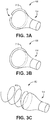
- FIGS. 3A-3C are perspective views of other examples of venous valve prostheses 100.
- the venous valve prosthesis 100 may include a frame 110 and a valve body 114.
- the frame 110 may have different shapes than the latticed structure illustrated in FIGS. 1A-2B .
- the venous valve prosthesis 100 may include a frame 210 and a valve body 114, where the frame 210 defines an open ring.
- the frame 210 may substantially form a ring shape but may define a gap 124 such that it does not define a complete ring.
- the frame 210 is configured to expand to engage wall 105 of the vein 102 (or other vasculature) in order to anchor the valve body 114 within the vein 102 (or other vasculature).
- the open ring structure of the frame 210 may enable the frame 210 to accommodate a range of different vein sizes.
- the open ring structure may enable the frame 210 to expand or contract as needed to engage with different diameter veins.
- the venous valve prosthesis 100 may include a frame 310 and the valve body 114.
- the frame 310 may define a closed ring.
- the frame 310 may form a ring shape with no gaps.
- the frame 310 is expandable from a compressed state to an expanded state in which the frame 310 engages the wall 105 of the vein 102 (or other vasculature) in order to anchor the valve body 114 within the vein 102 (or other vasculature).
- the venous valve prosthesis 100 may include a frame 410 and the valve body 114.
- the frame 410 may define a coil, which may exhibit spring-like characteristics.
- the frame 410 may form a helical shape.
- the frame 410 is expandable from a compressed state to an expanded state in which the frame 410 engages the wall 105 of the vein 102 (or other vasculature) in order to anchor the valve body 114 within the vein 102 (or other vasculature).
- the coil structure of the frame 410 may enable the frame 210 to accommodate a range of different vein sizes.
- the coil structure of the frame 410 may enable the frame 410 to expand or contract as needed to engage with different diameter veins.
- a frame 110 may define any suitable shape according to particular needs.
- the shapes described, including the latticed structure, the open ring, the closed ring, and the coil, may facilitate collapse of the frame 110, 210, 310, or 410, respectively, for delivery via a delivery catheter and may facilitate expansion of the frame 110, 210, 310, or 410, respectively, when delivered within the vein 102.
- FIGS. 4A-4C are perspective views of other examples of the valve body 114 of the venous valve prosthesis 100.
- a valve body 214 may include a downstream portion 226, which may be a portion of the valve body 214 downstream from the neck 122 when the valve body 214 is implanted in the vein 102 and having a length L1, and an upstream portion 228, which may be a portion of the valve body 214 upstream from neck 122 when the valve body 214 is implanted in the vein 102. As shown in FIG. 4A , a downstream portion 226, which may be a portion of the valve body 214 downstream from the neck 122 when the valve body 214 is implanted in the vein 102 and having a length L1, and an upstream portion 228, which may be a portion of the valve body 214 upstream from neck 122 when the valve body 214 is implanted in the vein 102. As shown in FIG.
- a valve body 314 may include a downstream portion 326, which may be a portion of the valve body 314 downstream from the neck 122 when the valve body 314 is implanted in the vein 102 and having a length L2, and an upstream portion 328 which may be a portion of the valve body 314 upstream from the neck 122 when the valve body 314 is implanted in the vein 102.
- the downstream portion 226 or 326 may have any suitable length.
- the downstream portion 226 of valve body 214 may have a length L1 that may be relatively long, as shown in FIG.
- the downstream portion 326 of the valve body 314 may have a length L2 that may be relatively short, as shown in FIG. 4B .
- a longer downstream portion such as the downstream portion 226 of the valve body 214 having length L1
- a shorter downstream portion such as the downstream portion 326 of the valve body 314 having length L2
- the length and other characteristics of the downstream portion 226 or 326, such as its diameter and material composition, may be adjusted accordingly according to particular needs.
- the valve body 114 may include a plurality of structural support members that help provide the valve body 114 with sufficient rigidity, for example, to help prevent the valve body 114 from inverting in the presence of back pressure on the valve body 114 (in a direction towards the frame 110, such as from retrograde fluid flow).
- a valve body 414 may define a plurality of ribs 430 such that the valve body 414 defines a ribbed exterior surface.
- the ribs 430 may be configured to maintain structural integrity of the valve body 414.
- the ribs 430 may extend along the length of the valve body 414.
- a valve body may define a substantially smooth exterior surface.
- the ribs 430 may be located on an interior surface of a valve body. In other examples, the ribs 430 may be located within the material of a valve body, between the inner and outer surfaces of the valve body, such that the ribs 430 are not visible on the exterior or interior surfaces of the valve body. In some examples, such as the example shown in FIG. 4C , the ribs 430 may be on portions of the valve body 414 other than the neck 122, including a downstream portion 426 and an upstream portion 428, and may not be on the neck 122. This may result in the neck 122 being more flexible than other portions of the valve body 414, which may facilitate folding of the valve body 414 about the neck 122.
- FIGS. 5A-5C are perspective views of several exemplary downstream openings 120a on a downstream portion of the valve body 114.
- FIG. 5A shows a downstream portion 526 of an example valve body 514.
- a downstream opening 520a may be substantially round.
- FIG. 5B shows a downstream portion 626 of an example valve body 614.
- a downstream opening 620a may be substantially oval.
- An oval downstream opening 620a may help facilitate closure of the downstream portion 626 of the valve body 614 in the absence of fluid flow through the valve body 614.
- the oval opening may tend to collapse (e.g., such that the walls of the downstream portion 626 move inward towards a longitudinal center of the downstream portion 626) more quickly than the round opening 520a ( FIG. 5A ).
- FIG. 5C shows a downstream portion 726 of an example valve body 714.
- the downstream portion 726 of the valve body 714 may define one or more creases.
- the downstream portion 726 defines two creases on opposite sides of the downstream portion 726 such that the downstream opening 720a is in the shape of two half-moons joined at each end. This shape may facilitate collapse of the downstream portion 726 of the valve body 714 as the downstream portion 726 may fold relatively flat to collapse in the absence of antegrade fluid flow, in the presence of retrograde fluid flow, and/or when fluid flow is static. This may additionally facilitate folding of the valve body 714 about the neck 112.
- valve body 714 may more easily fold about the neck 122 when the downstream portion 726 is flattened. This may facilitate proper functioning of the venous valve prosthesis 100 and, thus, proper blood flow through the vein 102. This may prevent undesirable retrograde blood flow through the vein 102 and the resulting negative effects to the patient.
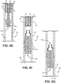
- FIGS. 6A-6G are partial, cross-sectional views of a system including the venous valve prosthesis 100 of FIGS. 1A-2B in various stages of use at a treatment site comprising a native venous valve 108 in the vein 102 of the patient.
- the vein 102 may comprise a wall 105 defining the vein lumen 106.
- the venous valve prosthesis 100 may be implanted such that it at least partially overlaps with a native venous valve 108.
- the treatment site may be located downstream or upstream of the native venous valve 108 or in any other suitable location, according to particular needs of the particular patient.
- FIG. 7 is a flowchart illustrating a method including the various stages of use of the system shown in FIGS. 6A-6G
- a guidewire 130 may be inserted into the vein 102 of a patient ( FIG. 6A and 752 of FIG. 7 ).
- the guidewire 130 may be advanced through the vein lumen 106 of the vein 102 to position a leading end (distal end) of the guidewire 130 at a target location as determined by the clinician.
- An outer catheter 132 may be introduced over the guidewire 130 and a distal portion of the outer catheter 132 may be advanced substantially adjacent to a treatment site as determined by the clinician ( FIG 6B and 754 of FIG, 7 ).
- the outer catheter 132 may define an outer catheter lumen 134.
- the guidewire 130 may be retracted to remove the guidewire 130 from the outer catheter lumen 134 ( FIG. 6C and 756 of FIG. 7 ), while leaving the outer catheter 132 in place.
- An inner catheter 136 may be introduced within the outer catheter 132 and a distal portion of inner catheter 136 may be advanced proximate to the treatment site ( FIG 6D and 758 of FIG. 7 ). In some examples, the distal portion of inner catheter 136 may be advanced to be substantially even with the distal portion of outer catheter 132.
- the inner catheter 136 may define an inner catheter lumen 138.
- a distal portion of the inner catheter lumen 138 may house the venous valve prosthesis 100.
- a plunger 140 may also be located in the inner catheter lumen 138, proximal of the venous valve prosthesis 100, and may be configured to help release the venous valve prosthesis 100 from the inner catheter lumen 138 as desired.
- the venous valve prosthesis 100 may be released from the inner catheter lumen 138 and to the treatment site ( FIG. 6E and 6F and 760 of FIG, 7 ).
- the plunger 140 may be advanced within the inner catheter lumen 138 to push the venous valve prosthesis 100 from the distal portion of the inner catheter lumen 138.
- a clinician may control the plunger 140 to advance the plunger 140 such that the venous valve prosthesis 100 is advanced from the inner catheter 136.
- the frame 110 may expand such that it is secured against the wall 105 of the vein 102 and anchors the valve body 114 within the vein 102.
- the frame 110 is illustrated as being self-expanding (e.g., formed from a shape memory material), in other examples, the frame 110 may be expanded via a balloon or other mechanism.
- the outer catheter 130, the inner catheter 134, and the plunger 138 may be removed from the vein 102 ( FIG. 6G and 762 of FIG. 7 ).
- one or more of the guidewire 130, the outer catheter 132, the inner catheter 136, the venous valve prosthesis 100, and/or the plunger 140 may each include one or more radiopaque markers or otherwise include a radiopaque material.
- the radiopaque markers or other radiopaque material may facilitate implantation of the venous valve prosthesis 100 within a patient.
- the radiopaque markers or other radiopaque material may help a clinician visualize the location of the respective component(s) with respect to the treatment site.
- the method used to deliver the venous valve prosthesis 100 may be simpler and less invasive than methods needed to implant other types of venous valve prostheses.
- the venous valve prosthesis 100 may be implanted in vasculature of a patient via a percutaneous procedure, rather than via a more invasive procedure that requires a vein to be cut open in order to place the valve prosthesis 100 inside the vein.
- the inner catheter 136 may include additional and/or different components for securing and releasing the venous valve prosthesis 100.
- the inner catheter lumen 138 may be configured to receive a tethering device for delivering the venous valve prosthesis 100 to the treatment site.
- the system may alternatively deliver the venous valve prosthesis 100 from an upstream direction and the venous valve prosthesis 100 may be positioned within the inner catheter lumen 138 such that the downstream opening 120a is located at a distal end of the venous valve prosthesis 100 as the venous valve prosthesis 100 is being delivered.
- a single catheter may include a delivery lumen for the venous valve prosthesis 100 and a guidewire lumen for passage of the guidewire 128 and may be used to deliver the venous valve prosthesis 100 without a need for a second catheter.
- a balloon or other mechanism may be used to expand the frame 110.
- downstream opening 120a is illustrated as being concentric with the upstream opening 120b, the stent lumen 112, and the valve lumen 118, the downstream opening 120a may, in come examples, be axially offset.
Landscapes
- Health & Medical Sciences (AREA)
- Cardiology (AREA)
- Engineering & Computer Science (AREA)
- Biomedical Technology (AREA)
- Heart & Thoracic Surgery (AREA)
- Transplantation (AREA)
- Oral & Maxillofacial Surgery (AREA)
- Vascular Medicine (AREA)
- Life Sciences & Earth Sciences (AREA)
- Animal Behavior & Ethology (AREA)
- General Health & Medical Sciences (AREA)
- Public Health (AREA)
- Veterinary Medicine (AREA)
- Prostheses (AREA)
Description
- This disclosure relates to an implantable medical device, and more specifically to venous valve prostheses.
- Venous valves are found within the vasculature of a mammal, particularly the veins. Venous valves prevent the backflow of blood during circulation. For example, venous valves help to fight backflow of blood in the legs caused by gravity pulling the blood away from the heart and back towards the feet of a person when standing. However, when venous valves fail to work properly, blood can flow backwards within the veins and pool in, for example, the legs. Such pooling of blood can cause the veins to become distended, thereby causing the venous valves to fail further. This progressively worsening disorder can lead to varicose veins and chronic venous insufficiency, which is painful and can lead to lower limb ulcerations.
- Native venous valves are valves created by thin, overlapping leaflets of tissue that open in response to antegrade pressure, but close in response to retrograde pressure. These valves may be reconstructed in a surgical procedure, but are complicated to reconstruct. Known prosthetic venous valves that attempt to replicate the function of the native leaflet design are complicated to fabricate, may require extensive invasive surgery to implant, may be damaged if implanted by percutaneous delivery, and tend to form thrombosis soon after implementation.
- In some aspects, this disclosure describes example venous valve prostheses that are implantable medical devices. Each implantable medical device may include a frame defining a frame lumen and a valve body defining a valve lumen. The valve body may be connected to the frame such that the valve lumen is in fluid communication with the frame lumen. The frame may be expandable such that it may expand when deployed to a treatment area such that it may anchor the valve body within the treatment area which may be, for example, an area of a vein comprising a native venous valve. The valve body may comprise a neck and may be configured to fold about the neck to at least partially close the valve lumen in an absence of fluid flow through the valve lumen or in the presence of retrograde fluid flow, and to open in the presence of antegrade fluid flow through the valve lumen. The valve body may be further configured to collapse in the absence of fluid flow through the valve lumen to at least partially close the valve lumen.
- In some examples, the implantable medical device may be delivered to a treatment site via a delivery catheter. A distal portion of the delivery catheter may be advanced to the treatment site and the implantable medical device may be deployed from the delivery catheter to the treatment site. In some examples, the treatment site may be an area of a vein, such as a vein within a leg of a patient, comprising a venous valve.
- In general, in one aspect, the present disclosure describes an implantable medical device comprising a frame and a flexible tubular valve body. The frame defines a frame lumen and is expandable from a compressed configuration to an expanded configuration. The flexible tubular valve body extends between a downstream end and an upstream end. The valve body defines a valve lumen, a downstream opening at the downstream end, and an upstream opening at the upstream end. The valve body is attached to the frame such that the frame lumen is in fluid communication with the valve lumen. The valve body comprises a neck and is configured to fold about the neck to at least partially close the valve lumen in an absence of fluid flow through the valve lumen or in the presence of retrograde fluid flow, and the valve body is configured to open in the presence of antegrade fluid flow through the valve lumen. In some embodiments, the valve body is further configured to collapse in an absence of fluid flow through the valve lumen to at least partially close the valve lumen.
- In various embodiments of the implantable medical device, the downstream opening is smaller than the upstream opening.
- In certain embodiments of the implantable medical device, the downstream opening is circular. In certain other embodiments, the downstream opening is oval.
- In various embodiments of the implantable medical device, a downstream portion of the valve body defines at least one crease such that the valve body is configured to preferentially fold along the crease to at least partially close the valve lumen.
- In various embodiments of the implantable medical device, the valve lumen decreases in diameter as it extends away from the frame. In certain embodiments, a thickness of a material forming the valve body is smaller at the neck than at least at one other portion of the valve body.
- In certain embodiments of the implantable medical device, the frame comprises steel. In certain other embodiments, the frame comprises nitinol.
- In certain embodiments of the implantable medical device, the frame defines a coil. In some other embodiments, the frame defines a latticed structure. In still other embodiments, the frame defines an open ring. In certain other embodiments, the frame defines a closed ring. In various embodiments, the frame may be a combination of these configurations.
- In some embodiments, valve body defines a ribbed exterior surface. In some other embodiments, the valve body defines a substantially smooth exterior surface.
- In various embodiments, the valve body comprises at least one of a polymer or a fluoropolymer.
- In various embodiments of the implantable medical device, the size of the downstream opening is approximately 50%-90% the size of the upstream opening.
- In general, in another aspect, the present disclosure describes a method comprising advancing a distal end of a catheter to a treatment site within a patient. An implantable medical device is disposed within the catheter. The method further comprises releasing the implantable medical device from the catheter at the treatment site. The implantable medical device comprises a frame and a flexible tubular valve body. The frame defines a frame lumen. The frame is expandable from a compressed configuration to an expanded configuration. The flexible tubular valve body extends between a downstream end and an upstream end. The valve body defines a valve lumen, a downstream opening at the downstream end, and an upstream opening at the upstream end. The valve body is attached to the frame such that the frame lumen is in fluid communication with the valve lumen. The valve body comprises a neck and is configured to fold about the neck to at least partially close the valve lumen in an absence of fluid flow through the valve lumen or in the presence of retrograde fluid, and the valve body is configured to open in the presence of antegrade fluid flow through the valve lumen. In certain embodiments, the valve body is further configured to collapse in the presence of retrograde fluid flow or in the absence of fluid flow through the valve lumen to at least partially close the valve lumen.
- In some embodiments, the method further comprises inserting a guide member into a vasculature of the patient, and advancing the distal end of the catheter to the treatment site over the guide member.
- In various embodiments, the treatment site comprises a native venous valve of the patient.
- In certain embodiments, the downstream opening is smaller than the upstream opening.
- In certain embodiments, the downstream opening is circular. In certain other embodiments, the downstream opening is oval.
- In some embodiments, a downstream portion of the valve defines at least one crease, the valve body being configured to preferentially fold along the crease to at least partially close the valve lumen.
- In various embodiments, the valve lumen decreases in diameter as it extends away from the frame.
- In various embodiments, a thickness of a material forming the valve body is smaller at the neck than at least at one other portion of the valve body.
- In certain embodiments, the frame comprises steel. In certain other embodiments, the frame comprises nitinol.
- In certain embodiments, the frame defines a coil. In certain other embodiments, the frame defines a latticed structure. In certain other embodiments, the frame defines an open ring. In still other embodiments, the frame defines a closed ring. In various embodiments, the frame may be a combination of these configurations.
- In some embodiments, the valve body defines a ribbed exterior surface. In certain other embodiments, the valve body defines a substantially smooth exterior surface.
- In various embodiments, the valve body comprises at least one of a polymer or a fluoropolymer.
- In various embodiments, the size of the downstream opening is approximately 50%-90% the size of the upstream opening.
- In general, in yet another aspect, the disclosure describes an implantable medical device comprises a frame and a flexible tubular valve body. The frame defines a frame lumen. The frame is expandable from a compressed configuration to an expanded configuration. The flexible tubular valve body extends between a downstream end and an upstream end. The valve body defines a valve lumen, a downstream opening at the downstream end, and an upstream opening at the upstream end. The valve body is attached to the frame such that the frame lumen is in fluid communication with the valve lumen. The valve body comprises a neck and is configured to fold about the neck to at least partially close the valve lumen in an absence of fluid flow through the valve lumen or in the presence of retrograde fluid flow, and the valve body is configured to open in the presence of antegrade fluid flow through the valve lumen. In some embodiments, the valve body is further configured to collapse in an absence of fluid flow through the valve lumen to at least partially close the valve lumen. The downstream opening is smaller than the upstream opening.
- In various embodiments, the frame comprises steel. In certain other embodiments, the frame comprises nitinol.
- In various embodiments, the frame defines a coil. In some other embodiments, the frame defines a latticed structure. In certain other embodiments, the frame defines an open ring. In still other embodiments, the frame defines a closed ring. In various embodiments, the frame may be a combination of these configurations.
- In various embodiments, the valve body defines a ribbed exterior surface. In some other embodiments, the valve body defines a substantially smooth exterior surface.
- In various embodiments, the size of the downstream opening is approximately 50%-90% the size of the upstream opening.
- In various embodiments, a downstream portion of the valve body defines at least one crease, the valve body being configured to preferentially fold along the crease to at least partially close the valve lumen.
- In various embodiments, the valve lumen decreases in diameter as it extends away from the frame.
- In certain embodiments, a thickness of a material forming the valve body is smaller at the neck than at least at one other portion of the valve body.
- In various embodiments, the valve body comprises at least one of a polymer or a fluoropolymer.
- The disclosure can be implemented to realize one or more of the following advantages. The implantable medical device may be delivered transluminally more easily than other implantable prosthetic venous valves, thereby also eliminating the need for extensive, open surgical procedures. The valve body may provide a more robust device that is easier to deliver transluminally compared to known prosthetic venous valves, especially known venous valves that attempt to replicate a leaf structure. The valve body is easier to fabricate than trying to replicate a native leaf structure. Further, the valve body has a more simple structure that helps alleviate the formation of thrombus. Further still, enabling transluminal delivery may reduce procedure time, virtually eliminated post-operative treatment and post-operative complications like infections, and helps recovery time.
- The details of one or more aspects of the disclosure are set forth in the accompanying drawings and the description below. As used herein, downstream or antegrade means towards the heart of a patient (i.e., downstream fluid flow means blood flowing towards the heart), and upstream or retrograde means away from the heart of a patient (i.e., upstream fluid flow means blood flowing away from the heart). Other features, objects, and advantages of the techniques described in this disclosure will be apparent from the description and drawings, and from the claims.
-
-
FIG. 1A is a cross-sectional view of an example venous valve prosthesis implanted within a vein of a leg of a patient. -
FIG. 1B is a cross-sectional view of the portion ofFIG. 1A labeled 1B, showing the exemplary venous valve prosthesis ofFIG. 1A implanted within a vein. -
FIG. 2A is a perspective view of the exemplary venous valve prosthesis ofFIGS. 1A and 1B showing the valve body in an unfolded configuration. -
FIG. 2B is a perspective view of the exemplary venous valve prosthesis ofFIGS. 1A and 1B showing the valve body in a folded configuration. -
FIGS. 3A-3C are perspective views of other examples of venous valve prostheses. -
FIGS. 4A-4C are a perspective views of other examples of the valve body of the exemplary venous valve prostheses ofFIGS. 1A-3C . -
FIGS. 5A-5C are perspective views of examples of the downstream opening of the valve body of the exemplary venous valve prostheses ofFIGS. 1A-4C . -
FIGS. 6A-6G are partial, cross-sectional views of a system including the exemplary venous valve prosthesis ofFIGS. 1A-2B in various stages of use at a treatment site comprising a venous valve in a vein of a patient. -
FIG. 7 is a flowchart illustrating a method including the various stages of use of the exemplary system shown inFIGS. 6A-6G . - In contrast to known prosthetic venous valves, the example venous valve prostheses described herein can be more easily delivered percutaneously, e.g., via a catheter percutaneously introduced into vasculature of a patient, without damage to the valve body. In addition, in some examples, the example venous valve prostheses described herein may help prevent thrombosis formation and be delivered to small veins.
- In some examples, a venous valve prosthesis includes a frame defining a frame lumen and a valve body defining a valve lumen. The valve body may be connected to the frame such that the valve lumen is in fluid communication with the frame lumen and the frame may act as an anchor for the valve body to secure the valve body within a vein (or other vasculature). The frame may be expandable such that it may expand when deployed to a treatment area such that it may anchor the valve body within the treatment area which may be, for example, an area of a vein comprising a native venous valve or an area adjacent to a native venous valve. For example, the frame may be self-expanding (e.g., formed from a shape memory material) or may be expanded via a balloon or other mechanism. The valve body may comprise a neck and may be configured to fold about the neck to, for example, at least partially close the valve lumen and minimize or even prevent fluid flow through the valve lumen in an absence of fluid flow (i.e., when fluid flow is static). The valve body may be further configured to collapse in the presence of retrograde fluid flow to at least partially close the valve lumen, e.g., to minimize or even prevent fluid flow through the valve lumen in a retrograde direction. Further still, the valve body may be configured to open in the presence of antegrade fluid flow to enable the antegrade fluid flow through the valve lumen and thus past the venous valve prosthesis.
- For example, the valve body may be configured to fold about the neck in the absence of fluid flow through the valve lumen (when fluid flow is static) and in a presence of retrograde fluid flow. In addition to, or instead of, folding about the neck in the absence of fluid flow through the valve lumen and in a presence of retrograde fluid flow, in some examples, the valve body may be configured to collapse in the presence of retrograde fluid flow, preventing flow through the valve lumen.
- A valve body defining a valve lumen, and configured to fold about a neck and/or configured to collapse in an absence of fluid flow to at least partially close the valve lumen may enable opening of the valve lumen in the presence of antegrade fluid flow and closing of the valve lumen in the absence of fluid flow. This may enable passage of antegrade blood flow though the valve body and prevent retrograde blood flow though the valve body such that the valve body may function as a venous valve to aid in correct blood circulation through the vein or other vasculature. Because the valve body may also be configured to fold about the neck in a presence of retrograde fluid flow and the valve body may be further configured to collapse in the presence of retrograde fluid flow, this may further prevent retrograde blood flow through the vein, further facilitating desired blood flow though the vein. Thus, the venous valve prostheses may prevent retrograde blood flow within the veins and may thus prevent pooling of blood in, for example, the legs, thereby preventing distended veins, varicose veins, chronic venous insufficiency, and lower limb ulcerations.
- In some examples, the venous valve prosthesis may be delivered to a treatment site via one or more catheters, which may be referred to herein as a delivery catheter. A distal portion of the catheter may be advanced to the treatment site and the venous valve prosthesis may be deployed from the delivery catheter to the treatment site. In some examples, the treatment site may be an area of a vein, such as a vein within a leg of a patient, comprising a native venous valve. The native venous valve may be, for example, not properly functioning, such that a clinician may determine that a venous valve prosthesis such as the ones described herein may help improve the patient's condition. In some examples, the treatment site may be adjacent to, downstream or upstream from a native venous valve. This implantation method may be simpler and less invasive than methods necessary to implant other types of venous valve prostheses, which may require additional implantation time, cost, pain, recovery, and risk.
- In the figures below, the full length of the delivery catheter and/or guidewire is not shown. The length of the delivery catheter and/or guidewire can vary depending on the type of interventional procedure.
- The venous valve prosthesis of the present disclosure may have particular application in a vein of a leg of a patient. However, the venous valve prosthesis may be used in any suitable location of the vasculature, or other hollow anatomical structures.
-
FIG. 1A is a schematic cross-sectional view of an exemplaryvenous valve prosthesis 100 implanted within avein 102 of aleg 104 of a patient. Thevein 102 may include avein wall 105 defining avein lumen 106 and thevenous valve prosthesis 100 may be implanted within thevein lumen 106. In the example shown inFIG. 1A , thevenous valve prosthesis 100 is configured to function as a valve in place of a nativevenous valve 108 of thevein 102, where the nativevenous valve 108 may not be functioning properly. In the example shown inFIG. 1A , thevenous valve prosthesis 100 is implanted to overlap with the nativevenous valve 108. Thevenous valve prosthesis 100 may push the nativevenous valve 108 up against thewalls 105 of thevein 102. Although the figures show space between the nativevenous valve 108 and thewalls 105 of thevein 102 and between the nativevenous valve 108, thevenous valve prosthesis 100 may push the nativevenous valve 108 against thewalls 105 of thevein 102 such that thevenous valve prosthesis 100 lies substantially flat against the nativevenous valve 108 and such that the nativevenous valve 108 lies substantially flat against thewalls 105. In some other examples, thevenous valve prosthesis 100 may be implanted within thevein lumen 106 upstream or downstream of the nativevenous valve 108. Thevenous valve prosthesis 100 may be configured to enable antegrade blood flow through thevenous valve prosthesis 100 to the heart of the patient and to prevent retrograde blood flow through thevenous valve prosthesis 100 away from the heart. Components and functions of thevenous valve prosthesis 100 are described in further detail below with reference toFIG. 1B . Thevenous valve prosthesis 100 may be implanted in avein 102 or other vasculature of a patient of any suitable size. In some examples, thevenous valve prosthesis 100 may be implanted in avein 102 with a diameter of 5 mm to 12 mm. -
FIG. 1B is a schematic cross-sectional view of the portion ofFIG. 1A labeled 1B, showing thevenous valve prosthesis 100 ofFIG. 1A implanted within thevein 102. In the example shown inFIG. 1B , thevenous valve prosthesis 100 includes aframe 110 and avalve body 114, which may be a flexible tubular valve body. - The
frame 110 may be expandable from a compressed configuration to an expanded configuration. In one example, theframe 110 may be self-expandable from the compressed configuration to the expanded configuration, e.g., without the aid of a balloon or other mechanism configured to apply an external force to theframe 110 to expand it. As another example, theframe 110 may be self-expandable from the compressed configuration to the expanded configuration via a balloon catheter introduced through aframe lumen 112 of theframe 110, or via another suitable technique. - In the example shown in
FIG. 1B , theframe 110 is in an expanded configuration. Theframe 110 may be configured to be able to expand further than shown inFIG. 1B , but further expansion of theframe 110 may be constrained by thewall 105 of thevein 102. Theframe 110 may define theframe lumen 112 which may widen as theframe 110 expands. When theframe 110 is in an expanded configuration, as shown inFIG. 1B , theframe lumen 112 may enable fluid flow through theframe lumen 112. Theframe 110 may be made of any suitable material. For example, theframe 110 may comprise steel. Alternatively or in addition, theframe 110 may comprise nitinol. - In the example shown in
FIG. 1B , theframe 110 defines a latticed structure. For example, theframe 110 may be configured like a stent, e.g., theframe 110 may comprise a plurality of struts that are arranged and connected to provide theframe 110 with the desired structure, geometry, and mechanical characteristics (e.g., structural integrity and expansion characteristics). In some examples, theframe 110 may define a tubular structure having open cells or closed cells that facilitate expansion of theframe 110 and provide theframe 110 with the desired mechanical characteristics. The stent-like structure of theframe 110 in the example shown inFIG. 1B may provide additional benefits. For example, in addition to anchoring thevalve body 114 within thevein 102, aframe 110 having a latticed structure, or another stent-like structure, may function as a stent to provide patency to thevein 102. In other examples, theframe 110 may define any suitable shape for securing theframe 110 and thevalve body 114 within thevein 102. - In some examples, as in the illustrated example, the
frame 110 may be configured to overlap and constrain the nativevenous valve 108 such that the nativevenous valve 108 does not obstruct blood flow or otherwise interfere with the functioning of thevenous valve prosthesis 100. In other examples, theframe 110 may not be configured to overlap the nativevenous valve 108 or to otherwise interact with the nativevenous valve 108. - In the example shown in
FIG. 1B , thevalve body 114 may be flexible and tubular and may extend between adownstream end 116a and anupstream end 116b. Thevalve body 114 may define avalve lumen 118, adownstream opening 120a at thedownstream end 116a, and anupstream opening 120b at theupstream end 116b. Thevalve body 114 may be attached to theframe 110 such that theframe lumen 112 is in fluid communication with thevalve lumen 118 and theframe 110 may act as an anchor for thevalve body 114 to secure thevalve body 114 within thevein 102. For example, in the illustrated example, theupstream end 116b of thevalve body 114 may be directly attached to theframe 110 or indirectly attached to theframe 110 via an intermediary structure positioned between thevalve body 114 and theframe 110. In some examples, thedownstream opening 120a of thevalve body 114 may be smaller than theupstream opening 120b. For example, the size of thedownstream opening 120a may be approximately 50%-90% of the size of theupstream opening 120b, such as about 80% of the size of theupstream opening 120b. Thedownstream opening 120a is selected to be large enough to prevent undue pooling of blood. In some examples, thevalve lumen 118 may decrease in diameter as it extends away from theframe 110. For example, thevalve lumen 118 may decrease in diameter from theupstream end 116a to aneck 122. - The
valve body 114 may comprise aneck 122 and may be configured to fold about theneck 122. In some examples, thevalve body 114 may be configured to fold about theneck 122 in an absence of fluid flow (when fluid flow is static) through thevalve lumen 118. This folding about theneck 122 may cause at least a portion of thevalve lumen 118 to close, thereby helping to prevent the flow of fluid through thevalve body 114. In some examples, thevalve body 114 may, in addition or alternatively, be configured to fold about theneck 122 in a presence of retrograde fluid flow, or configured to fold even further in the presence of retrograde fluid flow than in the presence of no fluid flow (when fluid flow is static). In some examples, thevalve body 114 may be configured to unfold in a presence of antegrade fluid flow. This configuration ofvalve body 114 may enable passage of desired (antegrade) blood flow through thevalve body 114 and restriction of undesired (retrograde) blood flow though thevalve body 114 to facilitate desired (antegrade) blood flow though thevein 102 and desired blood circulation through the patient while also restricting retrograde flow that may result in blood pooling, vessel distention, and varicose veins, and additional adverse effects to patient. - The
valve body 114 may also be configured to collapse in an absence of fluid flow through thevalve lumen 118 to at least partially close thevalve lumen 118. For example, in addition or alternatively to being configured to fold about theneck 122, thevalve body 114 may be configured to retract in a radial direction such that at least a portion ofvalve lumen 118 is at least partially closed, e.g., partially closed or, in other examples, completely or substantially closed, such that no fluid or substantially no significant amount of fluid flows through thevalve lumen 118 to one or both thedownstream opening 116a and/orupstream end 116b. - In some examples, the
valve body 114 may, in addition or alternatively, be configured to collapse in a presence of retrograde fluid flow. In some examples, thevalve body 114 may be configured to expand to its normal configuration in a presence of antegrade flow, resulting in reopening of thevalve lumen 118. This may enable passage of desired (antegrade) blood flow throughvalve body 114 and restriction of undesired (retrograde) blood flow though thevalve body 114 to facilitate desired (antegrade) blood flow though thevein 102 and desired blood circulation through the patient. - The
valve body 114 may comprise any suitable material. In some examples, thevalve body 114 may comprise at least one of a polymer or a fluoropolymer. In some examples, the material composition and/or shape of thevalve body 114 may facilitate the collapse and expansion of thevalve body 114, as desired. -
FIG. 2A is a perspective view of the exemplaryvenous valve prosthesis 100 ofFIGS. 1A and 1B showing thevalve body 114 in an unfolded configuration.FIG. 2B is a perspective view of the exemplaryvenous valve prosthesis 100 ofFIGS. 1A, 1B , and2A showing thevalve body 114 in a folded configuration. As discussed above with reference toFIGS. 1A and 1B , thevenous valve prosthesis 100 may include theframe 110 and thevalve body 114. In the illustrated example, theframe 110 may define a latticed structure. In other examples, theframe 110 may define any suitable shape. - The
valve body 114 may define theneck 122 and may be configured to fold about theneck 122, as shown inFIG. 2B . For example, thevalve body 114 may be configured to fold about theneck 122 in an absence of fluid flow throughvalve lumen 118, shown inFIGS. 1A and 1B . This folding about theneck 122 may cause at least a portion of thevalve lumen 118 to at least partially close and minimize, or even prevent, fluid flow through thevalve lumen 118. In some examples, thevalve body 114 may, in addition or alternatively, be configured to fold about theneck 122 in a presence of retrograde fluid flow. For example, in one embodiment, thevalve body 114 may be configured to fold about theneck 122 in the absence of fluid flow throughvalve lumen 118, thereby at least partially closing thevalve lumen 118, and configured to fold further about theneck 122 in the presence of retrograde fluid flow to further close or completely close thevalve lumen 118 to prevent retrograde fluid flow. - In some examples,
valve body 114 may be configured to unfold in a presence of antegrade fluid flow, as shown inFIG. 1A . In still other embodiments, thevalve body 114 maybe configured to unfold in the presence of antegrade fluid flow and in the absence of fluid flow throughvalve lumen 118, and configured to fold about theneck 122 in the presence of retrograde fluid flow. - This folding and unfolding of the
valve body 114 about theneck 122 may enable passage of desired (antegrade) blood flow through thevalve body 114 and restriction of undesired (retrograde) blood flow though thevalve body 114 to facilitate desired (antegrade) blood flow though thevein 102 and desired blood circulation through the patient and may thus prevent pooling of blood and other undesirable effects. - The
valve body 114 may be constructed in any suitable manner according to particular needs. In some examples, a thickness of a material forming thevalve body 114 may be smaller at theneck 122 than at least at one other portion of thevalve body 114. For example, avalve body 114 may be constructed of the same material but the material may be thinner at theneck 122 than at other portions of thevalve body 114. This may facilitate bending of thevalve body 114 at theneck 122 as theneck 122 may be more flexible than other portions of thevalve body 114 due to the decreased thickness of the material at theneck 122. - As another example, the portion of the
valve body 114 forming theneck 122 may be made of a different, more flexible, material than other portions of thevalve body 114. This may also facilitate bending of thevalve body 114 at theneck 122 as theneck 122 may be more flexible than other portions of thevalve body 114 due to the more flexible material at theneck 122. As another example, supportive ribs may be provided at portions of thevalve body 114 other than the neck 122 (seeFig. 4C , described further below), such that theneck 122 is more flexible than the ribbed portions and thus more able to bend than other portions of thevalve body 114. -
FIGS. 3A-3C are perspective views of other examples ofvenous valve prostheses 100. As described above with reference toFIGS. 1A-2B , thevenous valve prosthesis 100 may include aframe 110 and avalve body 114. Theframe 110 may have different shapes than the latticed structure illustrated inFIGS. 1A-2B . - For example, in the example illustrated in
FIG. 3A , thevenous valve prosthesis 100 may include aframe 210 and avalve body 114, where theframe 210 defines an open ring. Theframe 210 may substantially form a ring shape but may define agap 124 such that it does not define a complete ring. Theframe 210 is configured to expand to engagewall 105 of the vein 102 (or other vasculature) in order to anchor thevalve body 114 within the vein 102 (or other vasculature). The open ring structure of theframe 210 may enable theframe 210 to accommodate a range of different vein sizes. For example, the open ring structure may enable theframe 210 to expand or contract as needed to engage with different diameter veins. - In the example illustrated in
FIG. 3B , thevenous valve prosthesis 100 may include aframe 310 and thevalve body 114. Theframe 310 may define a closed ring. For example, theframe 310 may form a ring shape with no gaps. Theframe 310 is expandable from a compressed state to an expanded state in which theframe 310 engages thewall 105 of the vein 102 (or other vasculature) in order to anchor thevalve body 114 within the vein 102 (or other vasculature). - In the example illustrated in
FIG. 3C , thevenous valve prosthesis 100 may include aframe 410 and thevalve body 114. Theframe 410 may define a coil, which may exhibit spring-like characteristics. For example, theframe 410 may form a helical shape. Theframe 410 is expandable from a compressed state to an expanded state in which theframe 410 engages thewall 105 of the vein 102 (or other vasculature) in order to anchor thevalve body 114 within the vein 102 (or other vasculature). The coil structure of theframe 410 may enable theframe 210 to accommodate a range of different vein sizes. For example, similar to the open ring structure of the frame 210 (FIG. 3A ), the coil structure of theframe 410 may enable theframe 410 to expand or contract as needed to engage with different diameter veins. - Although certain examples are illustrated, a
frame 110 may define any suitable shape according to particular needs. The shapes described, including the latticed structure, the open ring, the closed ring, and the coil, may facilitate collapse of theframe frame vein 102. -
FIGS. 4A-4C are perspective views of other examples of thevalve body 114 of thevenous valve prosthesis 100. - As shown in
FIG. 4A , avalve body 214 may include adownstream portion 226, which may be a portion of thevalve body 214 downstream from theneck 122 when thevalve body 214 is implanted in thevein 102 and having a length L1, and anupstream portion 228, which may be a portion of thevalve body 214 upstream fromneck 122 when thevalve body 214 is implanted in thevein 102. As shown inFIG. 4B , avalve body 314 may include adownstream portion 326, which may be a portion of thevalve body 314 downstream from theneck 122 when thevalve body 314 is implanted in thevein 102 and having a length L2, and anupstream portion 328 which may be a portion of thevalve body 314 upstream from theneck 122 when thevalve body 314 is implanted in thevein 102. As shown inFIGS. 4A and 4B , thedownstream portion downstream portion 226 ofvalve body 214 may have a length L1 that may be relatively long, as shown inFIG. 4A , and thedownstream portion 326 of thevalve body 314 may have a length L2 that may be relatively short, as shown inFIG. 4B . In some examples, a longer downstream portion, such as thedownstream portion 226 of thevalve body 214 having length L1, may enable a larger folded portion and less force to fold when thevalve body 214 folds about theneck 122 and therefore better obstruction of flow. In some examples, a shorter downstream portion, such as thedownstream portion 326 of thevalve body 314 having length L2, may provide a more compact design and less likely obstruction of desired, antegrade, blood flow. The length and other characteristics of thedownstream portion - In some examples, the
valve body 114 may include a plurality of structural support members that help provide thevalve body 114 with sufficient rigidity, for example, to help prevent thevalve body 114 from inverting in the presence of back pressure on the valve body 114 (in a direction towards theframe 110, such as from retrograde fluid flow). For example, as shown inFIG. 4C , avalve body 414 may define a plurality ofribs 430 such that thevalve body 414 defines a ribbed exterior surface. Theribs 430 may be configured to maintain structural integrity of thevalve body 414. In some examples, theribs 430 may extend along the length of thevalve body 414. In other examples, a valve body may define a substantially smooth exterior surface. In other examples, theribs 430 may be located on an interior surface of a valve body. In other examples, theribs 430 may be located within the material of a valve body, between the inner and outer surfaces of the valve body, such that theribs 430 are not visible on the exterior or interior surfaces of the valve body. In some examples, such as the example shown inFIG. 4C , theribs 430 may be on portions of thevalve body 414 other than theneck 122, including adownstream portion 426 and anupstream portion 428, and may not be on theneck 122. This may result in theneck 122 being more flexible than other portions of thevalve body 414, which may facilitate folding of thevalve body 414 about theneck 122. - The
valve body 114 may define adownstream opening 120a having any suitable shape.FIGS. 5A-5C are perspective views of several exemplarydownstream openings 120a on a downstream portion of thevalve body 114.FIG. 5A shows adownstream portion 526 of anexample valve body 514. In the example illustrated inFIG. 5A , adownstream opening 520a may be substantially round.FIG. 5B shows adownstream portion 626 of anexample valve body 614. In the example illustrated inFIG. 5B , adownstream opening 620a may be substantially oval. An ovaldownstream opening 620a may help facilitate closure of thedownstream portion 626 of thevalve body 614 in the absence of fluid flow through thevalve body 614. For example, the oval opening may tend to collapse (e.g., such that the walls of thedownstream portion 626 move inward towards a longitudinal center of the downstream portion 626) more quickly than theround opening 520a (FIG. 5A ). -
FIG. 5C shows adownstream portion 726 of anexample valve body 714. In the example illustrated inFIG. 5C , thedownstream portion 726 of thevalve body 714 may define one or more creases. For example, in the example illustrated inFIG. 5C , thedownstream portion 726 defines two creases on opposite sides of thedownstream portion 726 such that thedownstream opening 720a is in the shape of two half-moons joined at each end. This shape may facilitate collapse of thedownstream portion 726 of thevalve body 714 as thedownstream portion 726 may fold relatively flat to collapse in the absence of antegrade fluid flow, in the presence of retrograde fluid flow, and/or when fluid flow is static. This may additionally facilitate folding of thevalve body 714 about theneck 112. For example, thevalve body 714 may more easily fold about theneck 122 when thedownstream portion 726 is flattened. This may facilitate proper functioning of thevenous valve prosthesis 100 and, thus, proper blood flow through thevein 102. This may prevent undesirable retrograde blood flow through thevein 102 and the resulting negative effects to the patient. -
FIGS. 6A-6G are partial, cross-sectional views of a system including thevenous valve prosthesis 100 ofFIGS. 1A-2B in various stages of use at a treatment site comprising a nativevenous valve 108 in thevein 102 of the patient. Thevein 102 may comprise awall 105 defining thevein lumen 106. In the illustrated example, thevenous valve prosthesis 100 may be implanted such that it at least partially overlaps with a nativevenous valve 108. In other examples, the treatment site may be located downstream or upstream of the nativevenous valve 108 or in any other suitable location, according to particular needs of the particular patient.FIG. 7 is a flowchart illustrating a method including the various stages of use of the system shown inFIGS. 6A-6G - A
guidewire 130 may be inserted into thevein 102 of a patient (FIG. 6A and 752 ofFIG. 7 ). Theguidewire 130 may be advanced through thevein lumen 106 of thevein 102 to position a leading end (distal end) of theguidewire 130 at a target location as determined by the clinician. - An
outer catheter 132 may be introduced over theguidewire 130 and a distal portion of theouter catheter 132 may be advanced substantially adjacent to a treatment site as determined by the clinician (FIG 6B and 754 ofFIG, 7 ). Theouter catheter 132 may define anouter catheter lumen 134. - The
guidewire 130 may be retracted to remove theguidewire 130 from the outer catheter lumen 134 (FIG. 6C and 756 ofFIG. 7 ), while leaving theouter catheter 132 in place. - An
inner catheter 136 may be introduced within theouter catheter 132 and a distal portion ofinner catheter 136 may be advanced proximate to the treatment site (FIG 6D and 758 ofFIG. 7 ). In some examples, the distal portion ofinner catheter 136 may be advanced to be substantially even with the distal portion ofouter catheter 132. Theinner catheter 136 may define aninner catheter lumen 138. A distal portion of theinner catheter lumen 138 may house thevenous valve prosthesis 100. Aplunger 140 may also be located in theinner catheter lumen 138, proximal of thevenous valve prosthesis 100, and may be configured to help release thevenous valve prosthesis 100 from theinner catheter lumen 138 as desired. - The
venous valve prosthesis 100 may be released from theinner catheter lumen 138 and to the treatment site (FIG. 6E and 6F and 760 ofFIG, 7 ). For example, theplunger 140 may be advanced within theinner catheter lumen 138 to push thevenous valve prosthesis 100 from the distal portion of theinner catheter lumen 138. For example, a clinician may control theplunger 140 to advance theplunger 140 such that thevenous valve prosthesis 100 is advanced from theinner catheter 136. As thevenous valve prosthesis 100 is released from a distal end of theinner catheter lumen 138, theframe 110 may expand such that it is secured against thewall 105 of thevein 102 and anchors thevalve body 114 within thevein 102. Although theframe 110 is illustrated as being self-expanding (e.g., formed from a shape memory material), in other examples, theframe 110 may be expanded via a balloon or other mechanism. - After satisfactory delivery of the
venous valve prosthesis 100, theouter catheter 130, theinner catheter 134, and theplunger 138 may be removed from the vein 102 (FIG. 6G and 762 ofFIG. 7 ). - In some examples, one or more of the
guidewire 130, theouter catheter 132, theinner catheter 136, thevenous valve prosthesis 100, and/or theplunger 140 may each include one or more radiopaque markers or otherwise include a radiopaque material. The radiopaque markers or other radiopaque material may facilitate implantation of thevenous valve prosthesis 100 within a patient. For example, the radiopaque markers or other radiopaque material may help a clinician visualize the location of the respective component(s) with respect to the treatment site. - Due at least in part to the relative mechanical simplicity of the design of the
venous valve prosthesis 100, the relative size, and the minimal components, the method used to deliver thevenous valve prosthesis 100 may be simpler and less invasive than methods needed to implant other types of venous valve prostheses. For example, as discussed with respect toFIGS. 6A-6G , thevenous valve prosthesis 100 may be implanted in vasculature of a patient via a percutaneous procedure, rather than via a more invasive procedure that requires a vein to be cut open in order to place thevalve prosthesis 100 inside the vein. - Although an example of use of a system for delivery of the
venous valve prosthesis 100 has been described, any suitable modification may be made according to particular needs, including performing the steps in a different order and/or performing more, fewer steps, and/or different steps. In some examples, theinner catheter 136 may include additional and/or different components for securing and releasing thevenous valve prosthesis 100. For example, theinner catheter lumen 138 may be configured to receive a tethering device for delivering thevenous valve prosthesis 100 to the treatment site. Although the system is illustrated as delivering thevenous valve prosthesis 100 from a downstream direction and thevenous valve prosthesis 100 is illustrated as being positioned within theinner catheter lumen 138 such that thedownstream opening 120a is located at a proximal end of thevenous valve prosthesis 100 as thevenous valve prosthesis 100 is being delivered, the system may alternatively deliver thevenous valve prosthesis 100 from an upstream direction and thevenous valve prosthesis 100 may be positioned within theinner catheter lumen 138 such that thedownstream opening 120a is located at a distal end of thevenous valve prosthesis 100 as thevenous valve prosthesis 100 is being delivered. - Although two catheters are illustrated as being used to deliver the
venous valve prosthesis 100, more or fewer catheters may be used according to particular needs. For example, a single catheter may include a delivery lumen for thevenous valve prosthesis 100 and a guidewire lumen for passage of the guidewire 128 and may be used to deliver thevenous valve prosthesis 100 without a need for a second catheter. In some examples, a balloon or other mechanism may be used to expand theframe 110. - Although the
downstream opening 120a is illustrated as being concentric with theupstream opening 120b, thestent lumen 112, and thevalve lumen 118, thedownstream opening 120a may, in come examples, be axially offset. - Various examples have been described. These and other examples are within the scope of the following claims.
- Further disclosed herein is the subject-matter of the following clauses:
- 1. An implantable medical device comprising:
- a frame defining a frame lumen, the frame being expandable from a compressed configuration to an expanded configuration; and
- a flexible tubular valve body extending between a downstream end and an upstream end, the valve body defining a valve lumen, a downstream opening at the downstream end, and an upstream opening at the upstream end, wherein the valve body is attached to the frame such that the frame lumen is in fluid communication with the valve lumen, the valve body comprising a neck and being configured to fold about the neck to at least partially close the valve lumen in an absence of fluid flow through the valve lumen or in the presence of retrograde fluid flow, and the valve body configured to unfold about the neck to open in the presence of antegrade fluid flow through the valve lumen.
- 2. The implantable medical device of
clause 1, wherein the downstream opening is smaller than the upstream opening. - 3. The implantable medical device of
clause 1 or 2, wherein the downstream opening is circular. - 4. The implantable medical device of
clause 1 or 2, wherein the downstream opening is oval. - 5. The implantable medical device of any of clauses 1-4, wherein a downstream portion of the valve defines at least one crease, the valve body being configured to preferentially fold along the crease to at least partially close the valve lumen.
- 6. The implantable medical device of any of clauses 1-5, wherein the valve lumen decreases in diameter as it extends away from the frame.
- 7. The implantable medical device of any of clauses 1-6, wherein a thickness of a material forming the valve body is smaller at the neck than at least at one other portion of the valve body.
- 8. The implantable medical device of any of clauses 1-7, wherein the frame comprises steel.
- 9. The implantable medical device of any of clauses 1-8, wherein the frame comprises nitinol.
- 10. The implantable medical device of any of clauses 1-9, wherein the frame defines a coil.
- 11. The implantable medical device of any of clauses 1-9, wherein the frame defines a latticed structure.
- 12. The implantable medical device of any of clauses 1-9, wherein the frame defines an open ring.
- 13. The implantable medical device of any of clauses 1-9, wherein the frame defines a closed ring.
- 14. The implantable medical device of any of clauses 1-13, wherein the valve body defines a ribbed exterior surface.
- 15. The implantable medical device of any of clauses 1-13, wherein the valve body defines a substantially smooth exterior surface.
- 16. The implantable medical device of any of clauses 1-15, wherein the valve body comprises at least one of a polymer or a fluoropolymer.
- 17. The implantable medical device of any of clauses 1-16, wherein the size of the downstream opening is approximately 50%-90% the size of the upstream opening.
- 18. An implantable medical device comprising:
- a frame defining a frame lumen, the frame being expandable from a compressed configuration to an expanded configuration; and
- a flexible tubular valve body extending between a downstream end and an upstream end, the valve body defining a valve lumen, a downstream opening at the downstream end, and an upstream opening at the upstream end, wherein the valve body is attached to the frame such that the frame lumen is in fluid communication with the valve lumen, the valve body comprising a neck and being configured to fold about the neck to at least partially close the valve lumen in an absence of fluid flow through the valve lumen or in the presence of retrograde fluid flow, and the valve body configured to unfold about the neck to open in the presence of antegrade fluid flow through the valve lumen,
- wherein the downstream opening is smaller than the upstream opening.
- 19. The implantable medical device of clause 18, wherein the frame comprises steel.
- 20. The implantable medical device of clauses 18 or 19, wherein the frame comprises nitinol.
- 21. The implantable medical device of any of clauses 18-20, wherein the frame defines a coil.
- 22. The implantable medical device of any of clauses 18-20, wherein the frame defines a latticed structure.
- 23. The implantable medical device of any of clauses 18-20, wherein the frame defines an open ring.
- 24. The implantable medical device of any of clauses 18-20, wherein the frame defines a closed ring.
- 25. The implantable medical device of any of clauses 18-24, wherein the valve body defines a ribbed exterior surface.
- 26. The implantable medical device of any of clauses 18-24, wherein the valve body defines a substantially smooth exterior surface.
- 27. The implantable medical device of any of clauses 18-26, wherein the size of the downstream opening is approximately 50%-90% the size of the upstream opening.
- 28. The implantable medical device of any of clauses 18-26, wherein a downstream portion of the valve body defines at least one crease, the valve body being configured to preferentially fold along the crease to at least partially close the valve lumen,
- 29. The implantable medical device of any of clauses 18-28, wherein the valve lumen decreases in diameter as it extends away from the frame.
- 30. The implantable medical device of any of clauses 18-29, wherein a thickness of a material forming the valve body is smaller at the neck than at least at one other portion of the valve body, and
- 31. The implantable medical device of any of clauses 18-30, wherein the valve body comprises at least one of a polymer or a fluoropolymer.
Claims (15)
- An implantable medical device comprising:a frame defining a frame lumen, the frame being expandable from a compressed configuration to an expanded configuration; anda flexible tubular valve body extending between a downstream end and an upstream end, the valve body defining a valve lumen, a downstream opening at the downstream end, and an upstream opening at the upstream end, wherein the valve body is attached to the frame such that the frame lumen is in fluid communication with the valve lumen, the valve body comprising a neck and being configured to fold about the neck to at least partially close the valve lumen in an absence of fluid flow through the valve lumen or in the presence of retrograde fluid flow, and the valve body configured to unfold about the neck to open in the presence of antegrade fluid flow through the valve lumen.
- The implantable medical device of claim 1, wherein the downstream opening is smaller than the upstream opening.
- The implantable medical device of claim 1 or 2, wherein the downstream opening is circular, or wherein the downstream opening is oval.
- The implantable medical device of any of claims 1-3, wherein a downstream portion of the valve defines at least one crease, the valve body being configured to preferentially fold along the crease to at least partially close the valve lumen.
- The implantable medical device of any of claims 1-4, wherein the valve lumen decreases in diameter as it extends away from the frame, and/or wherein a thickness of a material forming the valve body is smaller at the neck than at least at one other portion of the valve body.
- The implantable medical device of any of claims 1-5, wherein the frame comprises steel, and/or wherein the frame comprises nitinol.
- The implantable medical device of any of claims 1-6, wherein the frame defines a coil, or wherein the frame defines a latticed structure, or wherein the frame defines an open ring, or wherein the frame defines a closed ring.
- The implantable medical device of any of claims 1-7, wherein the valve body defines a ribbed exterior surface, or wherein the valve body defines a substantially smooth exterior surface.
- The implantable medical device of any of claims 1-8, wherein the valve body comprises at least one of a polymer or a fluoropolymer, and/or wherein the size of the downstream opening is approximately 50%-90% the size of the upstream opening.
- An implantable medical device comprising:a frame defining a frame lumen, the frame being expandable from a compressed configuration to an expanded configuration; anda flexible tubular valve body extending between a downstream end and an upstream end, the valve body defining a valve lumen, a downstream opening at the downstream end, and an upstream opening at the upstream end, wherein the valve body is attached to the frame such that the frame lumen is in fluid communication with the valve lumen, the valve body comprising a neck and being configured to fold about the neck to at least partially close the valve lumen in an absence of fluid flow through the valve lumen or in the presence of retrograde fluid flow, and the valve body configured to unfold about the neck to open in the presence of antegrade fluid flow through the valve lumen,wherein the downstream opening is smaller than the upstream opening.
- The implantable medical device of claim 10, wherein the frame comprises steel, and/or wherein the frame comprises nitinol.
- The implantable medical device of any of claims 10-11, wherein the frame defines a coil, or wherein the frame defines a latticed structure, or wherein the frame defines an open ring, or wherein the frame defines a closed ring.
- The implantable medical device of any of claims 10-12, wherein the valve body defines a ribbed exterior surface, or wherein the valve body defines a substantially smooth exterior surface.
- The implantable medical device of any of claims 10-13, wherein the size of the downstream opening is approximately 50%-90% the size of the upstream opening.
- The implantable medical device of any of claims 10-13, wherein a downstream portion of the valve body defines at least one crease, the valve body being configured to preferentially fold along the crease to at least partially close the valve lumen, and/or wherein the valve lumen decreases in diameter as it extends away from the frame, and/or wherein a thickness of a material forming the valve body is smaller at the neck than at least at one other portion of the valve body, and/or wherein the valve body comprises at least one of a polymer or a fluoropolymer.
Applications Claiming Priority (1)
| Application Number | Priority Date | Filing Date | Title |
|---|---|---|---|
| US15/211,868 US10098740B2 (en) | 2016-07-15 | 2016-07-15 | Venous valve prostheses |
Publications (2)
| Publication Number | Publication Date |
|---|---|
| EP3269329A1 true EP3269329A1 (en) | 2018-01-17 |
| EP3269329B1 EP3269329B1 (en) | 2020-01-15 |
Family
ID=59313121
Family Applications (1)
| Application Number | Title | Priority Date | Filing Date |
|---|---|---|---|
| EP17180531.0A Active EP3269329B1 (en) | 2016-07-15 | 2017-07-10 | Venous valve prostheses |
Country Status (3)
| Country | Link |
|---|---|
| US (1) | US10098740B2 (en) |
| EP (1) | EP3269329B1 (en) |
| CN (1) | CN107616857B (en) |
Families Citing this family (1)
| Publication number | Priority date | Publication date | Assignee | Title |
|---|---|---|---|---|
| US11564690B1 (en) | 2018-02-22 | 2023-01-31 | Avenu Medical, Inc | Vascular flow control devices and methods |
Citations (3)
| Publication number | Priority date | Publication date | Assignee | Title |
|---|---|---|---|---|
| WO2003011179A2 (en) * | 2001-07-31 | 2003-02-13 | Wilson-Cook Medical Inc. | Prosthesis having a sleeve valve |
| WO2005011535A2 (en) * | 2003-07-31 | 2005-02-10 | Cook Incorporated | Prosthetic valve for implantation in a body vessel |
| WO2010129900A1 (en) * | 2009-05-07 | 2010-11-11 | Georgia Tech Research Corporation | Implantable prosthetic vascular valves |
Family Cites Families (13)
| Publication number | Priority date | Publication date | Assignee | Title |
|---|---|---|---|---|
| JP4399585B2 (en) | 1998-06-02 | 2010-01-20 | クック インコーポレイティド | Multi-sided medical device |
| EP1900343B1 (en) | 2000-01-31 | 2015-10-21 | Cook Biotech Incorporated | Stent valves |
| US7470247B2 (en) * | 2004-04-26 | 2008-12-30 | Gyrus Acmi, Inc. | Ureteral stent |
| US8012198B2 (en) * | 2005-06-10 | 2011-09-06 | Boston Scientific Scimed, Inc. | Venous valve, system, and method |
| US7569071B2 (en) | 2005-09-21 | 2009-08-04 | Boston Scientific Scimed, Inc. | Venous valve, system, and method with sinus pocket |
| US7563277B2 (en) * | 2005-10-24 | 2009-07-21 | Cook Incorporated | Removable covering for implantable frame projections |
| US7678144B2 (en) | 2007-01-29 | 2010-03-16 | Cook Incorporated | Prosthetic valve with slanted leaflet design |
| US8828079B2 (en) * | 2007-07-26 | 2014-09-09 | Boston Scientific Scimed, Inc. | Circulatory valve, system and method |
| WO2009094373A1 (en) * | 2008-01-22 | 2009-07-30 | Cook Incorporated | Valve frame |
| CA2749026C (en) * | 2008-09-29 | 2018-01-09 | Impala, Inc. | Heart valve |
| US8348997B2 (en) | 2009-02-24 | 2013-01-08 | Medtronic Vascular, Inc. | One-way replacement valve |
| CN103202735B (en) * | 2013-04-01 | 2016-02-10 | 杭州启明医疗器械有限公司 | Pulmonary artery valve replacement device and support thereof |
| JP2018530386A (en) * | 2015-10-13 | 2018-10-18 | ヴェナラム メディカル, エルエルシーVenarum Medical, Llc | Implantable valve and method |
-
2016
- 2016-07-15 US US15/211,868 patent/US10098740B2/en active Active
-
2017
- 2017-07-10 EP EP17180531.0A patent/EP3269329B1/en active Active
- 2017-07-13 CN CN201710567834.4A patent/CN107616857B/en active Active
Patent Citations (3)
| Publication number | Priority date | Publication date | Assignee | Title |
|---|---|---|---|---|
| WO2003011179A2 (en) * | 2001-07-31 | 2003-02-13 | Wilson-Cook Medical Inc. | Prosthesis having a sleeve valve |
| WO2005011535A2 (en) * | 2003-07-31 | 2005-02-10 | Cook Incorporated | Prosthetic valve for implantation in a body vessel |
| WO2010129900A1 (en) * | 2009-05-07 | 2010-11-11 | Georgia Tech Research Corporation | Implantable prosthetic vascular valves |
Also Published As
| Publication number | Publication date |
|---|---|
| CN107616857A (en) | 2018-01-23 |
| EP3269329B1 (en) | 2020-01-15 |
| US10098740B2 (en) | 2018-10-16 |
| CN107616857B (en) | 2020-01-10 |
| US20180014935A1 (en) | 2018-01-18 |
Similar Documents
| Publication | Publication Date | Title |
|---|---|---|
| US20250186207A1 (en) | Heart valve prosthesis placement for low coronary ostia height | |
| US11844693B2 (en) | Devices, systems and methods for accurate positioning of a prosthetic valve | |
| JP6211539B2 (en) | Invertible tissue valve and method | |
| JP6553761B2 (en) | Reverse delivery device and method for prosthesis | |
| ES3019365T3 (en) | Prosthetic heart valve | |
| CN113143542B (en) | Aortic valve insufficiency repair device and method | |
| JP5379852B2 (en) | Collapsible and re-expandable prosthetic heart valve cuff design and complementary technology application | |
| EP2344090B1 (en) | A stent deployment device | |
| JP5106537B2 (en) | Delivery tool for transdermal delivery of prostheses | |
| ES2976639T3 (en) | Prosthetic valve to replace a mitral valve | |
| US20210205083A1 (en) | Prosthesis, delivery device and methods of use | |
| US20160081829A1 (en) | Aortic insufficiency repair device and method | |
| JP2019503246A5 (en) | ||
| JP2013539395A (en) | Heart valve support structure | |
| EP2979664A1 (en) | Aortic valve prosthesis, particularly suitable for transcatheter implantation | |
| EP3269329B1 (en) | Venous valve prostheses | |
| US20220151776A1 (en) | Temporary Vascular Valve and Related Systems and Methods |
Legal Events
| Date | Code | Title | Description |
|---|---|---|---|
| PUAI | Public reference made under article 153(3) epc to a published international application that has entered the european phase |
Free format text: ORIGINAL CODE: 0009012 |
|
| STAA | Information on the status of an ep patent application or granted ep patent |
Free format text: STATUS: THE APPLICATION HAS BEEN PUBLISHED |
|
| AK | Designated contracting states |
Kind code of ref document: A1 Designated state(s): AL AT BE BG CH CY CZ DE DK EE ES FI FR GB GR HR HU IE IS IT LI LT LU LV MC MK MT NL NO PL PT RO RS SE SI SK SM TR |
|
| AX | Request for extension of the european patent |
Extension state: BA ME |
|
| STAA | Information on the status of an ep patent application or granted ep patent |
Free format text: STATUS: REQUEST FOR EXAMINATION WAS MADE |
|
| 17P | Request for examination filed |
Effective date: 20180627 |
|
| RBV | Designated contracting states (corrected) |
Designated state(s): AL AT BE BG CH CY CZ DE DK EE ES FI FR GB GR HR HU IE IS IT LI LT LU LV MC MK MT NL NO PL PT RO RS SE SI SK SM TR |
|
| GRAP | Despatch of communication of intention to grant a patent |
Free format text: ORIGINAL CODE: EPIDOSNIGR1 |
|
| STAA | Information on the status of an ep patent application or granted ep patent |
Free format text: STATUS: GRANT OF PATENT IS INTENDED |
|
| RIC1 | Information provided on ipc code assigned before grant |
Ipc: A61F 2/90 20130101ALI20181203BHEP Ipc: A61F 2/844 20130101AFI20181203BHEP Ipc: A61F 2/24 20060101ALI20181203BHEP |
|
| INTG | Intention to grant announced |
Effective date: 20190104 |
|
| GRAJ | Information related to disapproval of communication of intention to grant by the applicant or resumption of examination proceedings by the epo deleted |
Free format text: ORIGINAL CODE: EPIDOSDIGR1 |
|
| STAA | Information on the status of an ep patent application or granted ep patent |
Free format text: STATUS: REQUEST FOR EXAMINATION WAS MADE |
|
| GRAJ | Information related to disapproval of communication of intention to grant by the applicant or resumption of examination proceedings by the epo deleted |
Free format text: ORIGINAL CODE: EPIDOSDIGR1 |
|
| GRAP | Despatch of communication of intention to grant a patent |
Free format text: ORIGINAL CODE: EPIDOSNIGR1 |
|
| REG | Reference to a national code |
Ref country code: DE Ref legal event code: R079 Ref document number: 602017010851 Country of ref document: DE Free format text: PREVIOUS MAIN CLASS: A61F0002240000 Ipc: A61F0002860000 |
|
| GRAP | Despatch of communication of intention to grant a patent |
Free format text: ORIGINAL CODE: EPIDOSNIGR1 |
|
| STAA | Information on the status of an ep patent application or granted ep patent |
Free format text: STATUS: GRANT OF PATENT IS INTENDED |
|
| INTC | Intention to grant announced (deleted) | ||
| INTG | Intention to grant announced |
Effective date: 20190524 |
|
| INTG | Intention to grant announced |
Effective date: 20190603 |
|
| RIC1 | Information provided on ipc code assigned before grant |
Ipc: A61F 2/86 20130101AFI20190523BHEP |
|
| GRAJ | Information related to disapproval of communication of intention to grant by the applicant or resumption of examination proceedings by the epo deleted |
Free format text: ORIGINAL CODE: EPIDOSDIGR1 |
|
| STAA | Information on the status of an ep patent application or granted ep patent |
Free format text: STATUS: REQUEST FOR EXAMINATION WAS MADE |
|
| GRAP | Despatch of communication of intention to grant a patent |
Free format text: ORIGINAL CODE: EPIDOSNIGR1 |
|
| STAA | Information on the status of an ep patent application or granted ep patent |
Free format text: STATUS: GRANT OF PATENT IS INTENDED |
|
| INTC | Intention to grant announced (deleted) | ||
| INTG | Intention to grant announced |
Effective date: 20190826 |
|
| GRAS | Grant fee paid |
Free format text: ORIGINAL CODE: EPIDOSNIGR3 |
|
| GRAA | (expected) grant |
Free format text: ORIGINAL CODE: 0009210 |
|
| STAA | Information on the status of an ep patent application or granted ep patent |
Free format text: STATUS: THE PATENT HAS BEEN GRANTED |
|
| AK | Designated contracting states |
Kind code of ref document: B1 Designated state(s): AL AT BE BG CH CY CZ DE DK EE ES FI FR GB GR HR HU IE IS IT LI LT LU LV MC MK MT NL NO PL PT RO RS SE SI SK SM TR |
|
| REG | Reference to a national code |
Ref country code: CH Ref legal event code: EP Ref country code: GB Ref legal event code: FG4D |
|
| REG | Reference to a national code |
Ref country code: IE Ref legal event code: FG4D |
|
| REG | Reference to a national code |
Ref country code: DE Ref legal event code: R096 Ref document number: 602017010851 Country of ref document: DE |
|
| REG | Reference to a national code |
Ref country code: AT Ref legal event code: REF Ref document number: 1224508 Country of ref document: AT Kind code of ref document: T Effective date: 20200215 |
|
| REG | Reference to a national code |
Ref country code: NL Ref legal event code: MP Effective date: 20200115 |
|
| REG | Reference to a national code |
Ref country code: LT Ref legal event code: MG4D |
|
| PG25 | Lapsed in a contracting state [announced via postgrant information from national office to epo] |
Ref country code: RS Free format text: LAPSE BECAUSE OF FAILURE TO SUBMIT A TRANSLATION OF THE DESCRIPTION OR TO PAY THE FEE WITHIN THE PRESCRIBED TIME-LIMIT Effective date: 20200115 Ref country code: NL Free format text: LAPSE BECAUSE OF FAILURE TO SUBMIT A TRANSLATION OF THE DESCRIPTION OR TO PAY THE FEE WITHIN THE PRESCRIBED TIME-LIMIT Effective date: 20200115 Ref country code: NO Free format text: LAPSE BECAUSE OF FAILURE TO SUBMIT A TRANSLATION OF THE DESCRIPTION OR TO PAY THE FEE WITHIN THE PRESCRIBED TIME-LIMIT Effective date: 20200415 Ref country code: FI Free format text: LAPSE BECAUSE OF FAILURE TO SUBMIT A TRANSLATION OF THE DESCRIPTION OR TO PAY THE FEE WITHIN THE PRESCRIBED TIME-LIMIT Effective date: 20200115 Ref country code: PT Free format text: LAPSE BECAUSE OF FAILURE TO SUBMIT A TRANSLATION OF THE DESCRIPTION OR TO PAY THE FEE WITHIN THE PRESCRIBED TIME-LIMIT Effective date: 20200607 |
|
| PG25 | Lapsed in a contracting state [announced via postgrant information from national office to epo] |
Ref country code: SE Free format text: LAPSE BECAUSE OF FAILURE TO SUBMIT A TRANSLATION OF THE DESCRIPTION OR TO PAY THE FEE WITHIN THE PRESCRIBED TIME-LIMIT Effective date: 20200115 Ref country code: LV Free format text: LAPSE BECAUSE OF FAILURE TO SUBMIT A TRANSLATION OF THE DESCRIPTION OR TO PAY THE FEE WITHIN THE PRESCRIBED TIME-LIMIT Effective date: 20200115 Ref country code: HR Free format text: LAPSE BECAUSE OF FAILURE TO SUBMIT A TRANSLATION OF THE DESCRIPTION OR TO PAY THE FEE WITHIN THE PRESCRIBED TIME-LIMIT Effective date: 20200115 Ref country code: GR Free format text: LAPSE BECAUSE OF FAILURE TO SUBMIT A TRANSLATION OF THE DESCRIPTION OR TO PAY THE FEE WITHIN THE PRESCRIBED TIME-LIMIT Effective date: 20200416 Ref country code: IS Free format text: LAPSE BECAUSE OF FAILURE TO SUBMIT A TRANSLATION OF THE DESCRIPTION OR TO PAY THE FEE WITHIN THE PRESCRIBED TIME-LIMIT Effective date: 20200515 Ref country code: BG Free format text: LAPSE BECAUSE OF FAILURE TO SUBMIT A TRANSLATION OF THE DESCRIPTION OR TO PAY THE FEE WITHIN THE PRESCRIBED TIME-LIMIT Effective date: 20200415 |
|
| REG | Reference to a national code |
Ref country code: DE Ref legal event code: R097 Ref document number: 602017010851 Country of ref document: DE |
|
| PG25 | Lapsed in a contracting state [announced via postgrant information from national office to epo] |
Ref country code: RO Free format text: LAPSE BECAUSE OF FAILURE TO SUBMIT A TRANSLATION OF THE DESCRIPTION OR TO PAY THE FEE WITHIN THE PRESCRIBED TIME-LIMIT Effective date: 20200115 Ref country code: SK Free format text: LAPSE BECAUSE OF FAILURE TO SUBMIT A TRANSLATION OF THE DESCRIPTION OR TO PAY THE FEE WITHIN THE PRESCRIBED TIME-LIMIT Effective date: 20200115 Ref country code: LT Free format text: LAPSE BECAUSE OF FAILURE TO SUBMIT A TRANSLATION OF THE DESCRIPTION OR TO PAY THE FEE WITHIN THE PRESCRIBED TIME-LIMIT Effective date: 20200115 Ref country code: CZ Free format text: LAPSE BECAUSE OF FAILURE TO SUBMIT A TRANSLATION OF THE DESCRIPTION OR TO PAY THE FEE WITHIN THE PRESCRIBED TIME-LIMIT Effective date: 20200115 Ref country code: ES Free format text: LAPSE BECAUSE OF FAILURE TO SUBMIT A TRANSLATION OF THE DESCRIPTION OR TO PAY THE FEE WITHIN THE PRESCRIBED TIME-LIMIT Effective date: 20200115 Ref country code: EE Free format text: LAPSE BECAUSE OF FAILURE TO SUBMIT A TRANSLATION OF THE DESCRIPTION OR TO PAY THE FEE WITHIN THE PRESCRIBED TIME-LIMIT Effective date: 20200115 Ref country code: SM Free format text: LAPSE BECAUSE OF FAILURE TO SUBMIT A TRANSLATION OF THE DESCRIPTION OR TO PAY THE FEE WITHIN THE PRESCRIBED TIME-LIMIT Effective date: 20200115 Ref country code: DK Free format text: LAPSE BECAUSE OF FAILURE TO SUBMIT A TRANSLATION OF THE DESCRIPTION OR TO PAY THE FEE WITHIN THE PRESCRIBED TIME-LIMIT Effective date: 20200115 |
|
| REG | Reference to a national code |
Ref country code: AT Ref legal event code: MK05 Ref document number: 1224508 Country of ref document: AT Kind code of ref document: T Effective date: 20200115 |
|
| PLBE | No opposition filed within time limit |
Free format text: ORIGINAL CODE: 0009261 |
|
| STAA | Information on the status of an ep patent application or granted ep patent |
Free format text: STATUS: NO OPPOSITION FILED WITHIN TIME LIMIT |
|
| 26N | No opposition filed |
Effective date: 20201016 |
|
| PG25 | Lapsed in a contracting state [announced via postgrant information from national office to epo] |
Ref country code: AT Free format text: LAPSE BECAUSE OF FAILURE TO SUBMIT A TRANSLATION OF THE DESCRIPTION OR TO PAY THE FEE WITHIN THE PRESCRIBED TIME-LIMIT Effective date: 20200115 Ref country code: IT Free format text: LAPSE BECAUSE OF FAILURE TO SUBMIT A TRANSLATION OF THE DESCRIPTION OR TO PAY THE FEE WITHIN THE PRESCRIBED TIME-LIMIT Effective date: 20200115 |
|
| PG25 | Lapsed in a contracting state [announced via postgrant information from national office to epo] |
Ref country code: MC Free format text: LAPSE BECAUSE OF FAILURE TO SUBMIT A TRANSLATION OF THE DESCRIPTION OR TO PAY THE FEE WITHIN THE PRESCRIBED TIME-LIMIT Effective date: 20200115 Ref country code: SI Free format text: LAPSE BECAUSE OF FAILURE TO SUBMIT A TRANSLATION OF THE DESCRIPTION OR TO PAY THE FEE WITHIN THE PRESCRIBED TIME-LIMIT Effective date: 20200115 Ref country code: PL Free format text: LAPSE BECAUSE OF FAILURE TO SUBMIT A TRANSLATION OF THE DESCRIPTION OR TO PAY THE FEE WITHIN THE PRESCRIBED TIME-LIMIT Effective date: 20200115 |
|
| REG | Reference to a national code |
Ref country code: CH Ref legal event code: PL |
|
| REG | Reference to a national code |
Ref country code: BE Ref legal event code: MM Effective date: 20200731 |
|
| PG25 | Lapsed in a contracting state [announced via postgrant information from national office to epo] |
Ref country code: CH Free format text: LAPSE BECAUSE OF NON-PAYMENT OF DUE FEES Effective date: 20200731 Ref country code: LI Free format text: LAPSE BECAUSE OF NON-PAYMENT OF DUE FEES Effective date: 20200731 Ref country code: LU Free format text: LAPSE BECAUSE OF NON-PAYMENT OF DUE FEES Effective date: 20200710 Ref country code: FR Free format text: LAPSE BECAUSE OF NON-PAYMENT OF DUE FEES Effective date: 20200731 |
|
| PG25 | Lapsed in a contracting state [announced via postgrant information from national office to epo] |
Ref country code: BE Free format text: LAPSE BECAUSE OF NON-PAYMENT OF DUE FEES Effective date: 20200731 |
|
| GBPC | Gb: european patent ceased through non-payment of renewal fee |
Effective date: 20210710 |
|
| PG25 | Lapsed in a contracting state [announced via postgrant information from national office to epo] |
Ref country code: GB Free format text: LAPSE BECAUSE OF NON-PAYMENT OF DUE FEES Effective date: 20210710 |
|
| PG25 | Lapsed in a contracting state [announced via postgrant information from national office to epo] |
Ref country code: TR Free format text: LAPSE BECAUSE OF FAILURE TO SUBMIT A TRANSLATION OF THE DESCRIPTION OR TO PAY THE FEE WITHIN THE PRESCRIBED TIME-LIMIT Effective date: 20200115 Ref country code: MT Free format text: LAPSE BECAUSE OF FAILURE TO SUBMIT A TRANSLATION OF THE DESCRIPTION OR TO PAY THE FEE WITHIN THE PRESCRIBED TIME-LIMIT Effective date: 20200115 Ref country code: CY Free format text: LAPSE BECAUSE OF FAILURE TO SUBMIT A TRANSLATION OF THE DESCRIPTION OR TO PAY THE FEE WITHIN THE PRESCRIBED TIME-LIMIT Effective date: 20200115 |
|
| PG25 | Lapsed in a contracting state [announced via postgrant information from national office to epo] |
Ref country code: MK Free format text: LAPSE BECAUSE OF FAILURE TO SUBMIT A TRANSLATION OF THE DESCRIPTION OR TO PAY THE FEE WITHIN THE PRESCRIBED TIME-LIMIT Effective date: 20200115 Ref country code: AL Free format text: LAPSE BECAUSE OF FAILURE TO SUBMIT A TRANSLATION OF THE DESCRIPTION OR TO PAY THE FEE WITHIN THE PRESCRIBED TIME-LIMIT Effective date: 20200115 |
|
| PGFP | Annual fee paid to national office [announced via postgrant information from national office to epo] |
Ref country code: IE Payment date: 20250623 Year of fee payment: 9 |
|
| PGFP | Annual fee paid to national office [announced via postgrant information from national office to epo] |
Ref country code: DE Payment date: 20250620 Year of fee payment: 9 |