EP3269311A1 - Tendon stripper - Google Patents
Tendon stripper Download PDFInfo
- Publication number
- EP3269311A1 EP3269311A1 EP17181054.2A EP17181054A EP3269311A1 EP 3269311 A1 EP3269311 A1 EP 3269311A1 EP 17181054 A EP17181054 A EP 17181054A EP 3269311 A1 EP3269311 A1 EP 3269311A1
- Authority
- EP
- European Patent Office
- Prior art keywords
- tendon
- shaft
- tip
- hook
- tendon stripper
- Prior art date
- Legal status (The legal status is an assumption and is not a legal conclusion. Google has not performed a legal analysis and makes no representation as to the accuracy of the status listed.)
- Granted
Links
Images
Classifications
-
- A—HUMAN NECESSITIES
- A61—MEDICAL OR VETERINARY SCIENCE; HYGIENE
- A61B—DIAGNOSIS; SURGERY; IDENTIFICATION
- A61B17/00—Surgical instruments, devices or methods
- A61B17/00008—Vein tendon strippers
-
- A—HUMAN NECESSITIES
- A61—MEDICAL OR VETERINARY SCIENCE; HYGIENE
- A61B—DIAGNOSIS; SURGERY; IDENTIFICATION
- A61B17/00—Surgical instruments, devices or methods
- A61B17/00234—Surgical instruments, devices or methods for minimally invasive surgery
-
- A—HUMAN NECESSITIES
- A61—MEDICAL OR VETERINARY SCIENCE; HYGIENE
- A61B—DIAGNOSIS; SURGERY; IDENTIFICATION
- A61B17/00—Surgical instruments, devices or methods
- A61B17/32—Surgical cutting instruments
- A61B17/320016—Endoscopic cutting instruments, e.g. arthroscopes, resectoscopes
-
- A—HUMAN NECESSITIES
- A61—MEDICAL OR VETERINARY SCIENCE; HYGIENE
- A61B—DIAGNOSIS; SURGERY; IDENTIFICATION
- A61B17/00—Surgical instruments, devices or methods
- A61B17/32—Surgical cutting instruments
- A61B17/3205—Excision instruments
-
- A—HUMAN NECESSITIES
- A61—MEDICAL OR VETERINARY SCIENCE; HYGIENE
- A61B—DIAGNOSIS; SURGERY; IDENTIFICATION
- A61B17/00—Surgical instruments, devices or methods
- A61B17/00234—Surgical instruments, devices or methods for minimally invasive surgery
- A61B2017/00349—Needle-like instruments having hook or barb-like gripping means, e.g. for grasping suture or tissue
-
- A—HUMAN NECESSITIES
- A61—MEDICAL OR VETERINARY SCIENCE; HYGIENE
- A61B—DIAGNOSIS; SURGERY; IDENTIFICATION
- A61B17/00—Surgical instruments, devices or methods
- A61B17/00234—Surgical instruments, devices or methods for minimally invasive surgery
- A61B2017/00353—Surgical instruments, devices or methods for minimally invasive surgery one mechanical instrument performing multiple functions, e.g. cutting and grasping
-
- A—HUMAN NECESSITIES
- A61—MEDICAL OR VETERINARY SCIENCE; HYGIENE
- A61B—DIAGNOSIS; SURGERY; IDENTIFICATION
- A61B17/00—Surgical instruments, devices or methods
- A61B17/32—Surgical cutting instruments
- A61B2017/320064—Surgical cutting instruments with tissue or sample retaining means
Definitions
- This disclosure relates to a tendon stripper for use in separating at least a portion of a tendon from adjacent muscle tissue.
- Tendon strippers are used to harvest tendons for use in orthopedic procedures.
- a tendon stripper is used to harvest at least a portion of a hamstring.
- the harvested hamstring tendon may then be used in an anterior cruciate ligament (ACL) reconstruction surgery, for example.
- ACL anterior cruciate ligament
- Tendons are also known to be harvested from other areas of the body, such as the wrist, and can used in other types of orthopedic procedures, such as ulna collateral ligament (UCL) reconstructions.
- UCL ulna collateral ligament
- This disclosure relates to a tendon stripper, which may be used to separate at least a portion of a tendon from adjacent muscle tissue.
- the harvested tendon can then be used in various orthopedic procedures, such as ACL and UCL reconstructions, to name a few examples.
- a tendon stripper includes, inter alia , a shaft including a tip tapering to a point at the distal end of the shaft, and a retention structure moveable between an open position and a closed position to capture and retain a tendon relative to the tip.
- the tip arrangement preferably increases the ease of separating a tendon from adjacent muscle tissue.
- a tendon stripper includes, inter alia , a shaft including a tip provided at a distal end of the shaft, and a retention structure moveable between an open position and a closed position, preferably to capture and retain a tendon relative to the tip.
- the retention structure is provided entirely in a common plane containing a centerline of the shaft.
- the retention structure arrangement preferably provides the retention structure with symmetry, which makes the tendon stripper easy to use on either side of a patient's body, and by either hand of the user.
- a method includes, inter alia , capturing a tendon in a retention structure of a tendon stripper, and moving the tendon stripper distally to separate at least a portion of a tendon from adjacent muscle tissue.
- the tendon stripper includes a shaft with a tip at a distal end of the shaft. The tip tapers to a point, which increases the ease of separating tendon from adjacent muscle.
- This disclosure relates to a tendon stripper, which may be used to separate one or more tendons from adjacent muscle tissue.
- a harvested tendon can then be used in various orthopedic procedures, such as ACL and UCL reconstructions, to name a few examples.
- a tendon stripper includes, inter alia , a shaft including a tip tapering to a point at the distal end of the shaft, and a retention structure moveable between an open position and a closed position to capture and retain a tendon relative to the tip.
- the tip arrangement preferably increases the ease of separating a tendon from adjacent muscle tissue.
- the tip tapers to a rounded point.
- the tip tapers to a sharp point.
- the point is coincident with a centerline of the shaft.
- the retention structure is a hook.
- the hook is provided entirely in a common plane containing a centerline of the shaft.
- the tendon stripper includes a handle.
- the shaft projects distally from the handle, and the handle includes a trigger provided in the common plane. Further, movement of the trigger moves the hook between the open and closed positions.
- movement of the trigger in the distal direction moves the hook to the open position.
- a tendon stripper includes, inter alia , a shaft including a tip provided at a distal end of the shaft, and a retention structure moveable between an open position and a closed position preferably to capture and retain a tendon relative to the tip.
- the retention structure is provided entirely in a common plane containing a centerline of the shaft.
- the retention structure arrangement provides the retention structure with symmetry, which makes the tendon stripper easy to use on either side of a patient's body, and by either hand of the user.
- the retention structure is a hook including a first linear portion, a second linear portion, and a curved portion connecting the first and second linear portions.
- the first and second linear portions are substantially parallel to one another along their respective lengths.
- the first linear portion is at least partially received within the shaft and mechanically coupled to a trigger provided in a handle. Further, the shaft projects distally from the handle, and movement of the trigger moves the hook between the open position and the closed position.
- the trigger is provided in the common plane.
- the second linear portion has a proximal end configured to be received in a socket adjacent the tip when the hook is in the closed position.
- the curved portion follows an arc defined by a circle having a center between the first and second linear portions. Further, the first and second linear portions are spaced-apart from one another by a distance substantially equal to a diameter of the circle along substantially their entire respective lengths.
- the curved portion makes substantially a 180° bend about the center to connect the first and second linear portions.
- the tip tapers to a point coincident with the centerline of the shaft.
- the retention structure includes one of a hook, a square, a loop, a corkscrew, and a slotted sleeve.
- the retention structure includes a straight leading edge.
- a method includes, inter alia , capturing a tendon in a retention structure of a tendon stripper, and moving the tendon stripper distally to separate at least a portion of a tendon from adjacent muscle tissue.
- the tendon stripper includes a shaft with a tip at a distal end of the shaft. The tip tapers to a point, which preferably increases the ease of separating tendon from adjacent muscle.
- the point of the tip is provided at a junction between the tendon and the muscle tissue during the separating step, and the point of the tip is coincident with a centerline of the shaft.
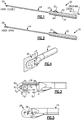
- Figure 1 illustrates an example tendon stripper 20.
- the tendon stripper 20 includes a handle 22, a shaft 24, and a retention structure.
- the retention structure is a hook 26.
- This disclosure is not limited to tendon strippers with hooks, however, and extends to other types of retention structures such as squares, loops, corkscrews, and slotted sleeves, to name a few examples.
- the shaft 24 projects from the handle 22 in a distal direction.
- the hook 26 is moveable relative to the shaft 24 between an open position ( Figure 2 ) in which a tendon 54 ( Figure 7 ) can be captured by the hook 26, and a closed position ( Figure 1 ) in which the captured tendon 54 is secured relative to a tip 28 of the shaft.
- the tip 28 is configured to separate the tendon 54 from adjacent muscle tissue 56 ( Figure 7 ).
- the hook 26 is selectively moveable between the open and closed positions by movement of a trigger 30 provided on the handle 22.
- the trigger 30 is configured for movement by a user's (e.g., a surgeon's) thumb.
- the trigger 30 is moveable in the distal and proximal directions to move the hook between the open and closed positions, respectively.
- the "proximal" and “distal” directions are labeled across the figures for purposes of explanation only.
- the trigger 30 is moveable to intermediate positions between the open and closed positions to accommodate different tendon sizes, for example. Further, in one example, the trigger 30 is mechanically biased to the closed position.
- the hook 26 is moveable relative to the shaft 24
- the shaft 24 could be moveable relative to the hook 26. In that case, the shaft 24 would be selectively moveable in response to movement of the trigger 30.
- the trigger 30 in this example is provided on a superior, or top, surface 32 of the handle 22.
- the handle 22 may also include a second trigger 34 (shown in phantom in Figure 1 ) on an inferior, or bottom, surface 36 of the handle 22.
- the first trigger 30 and the second trigger 34 are both configured to selectively move the hook 26 between the open and closed positions.
- the second trigger 34 moves with the first trigger 30.
- the second trigger 34 could move independently of the first trigger 30.
- the arrangement of the hook 26 allows for increased ease of capturing a tendon within the hook 26. Further, the hook 26 and tip 28 arrangement provides for increased functionality of the tendon stripper 20. Namely, the arrangement allows the tendon stripper 20 to be easily used on both sides of a patient's body, and by either hand of a user (e.g., a surgeon).
- the hook 26 is substantially U-shaped.
- the hook 26 includes a first linear portion 38, a second linear portion 40, and a curved portion 42 between the first and second linear portions 38, 40.
- the first and second linear portions 38, 40 extend in a linear direction along substantially straight lines, and are substantially parallel to one another along their entire respective lengths D 1 , D 2 .
- the first linear portion 38 has a length D 1 greater than the length D 2 of the second linear portion 40. Further, the first linear portion 38 is received at least partially inside the shaft 24, and is mechanically coupled to the trigger 30. The first linear portion 38 may be directly coupled to the trigger 30, or the tendon stripper 20 may include an intermediate actuator, such as a shaft or cable, configured to transmit force from the trigger 30 to the first linear portion 38.
- an intermediate actuator such as a shaft or cable
- the proximal end 44 of the second linear portion 40 is configured to be received in a socket 46 provided adjacent the tip 28.
- a tendon can be captured within the hook 26 by virtue of the space between the proximal end 44 of the second linear portion 40 and the tip 28.
- the curved portion 42 follows an arc defined by a circle having a center at an origin O 1 between the first and second linear portions 38, 40.
- the circle has a radius R 1 originating at origin O 1 and a diameter D 3 passing through origin O 1 .
- the curved portion 42 provides a semi-circle, and in this example makes a 180° bend about the origin O 1 to connect the first and second linear portions 38, 40.
- the first and second linear portions 38, 40 are spaced-apart from one another by a distance D 4 substantially equal to the diameter D 3 . Spacing the first and second linear portions 38, 40 apart from one another by the distance D 4 increases the ease of capturing a tendon within the hook 26.
- the tip 28 spans the entire distance D 4 between the first and second linear portions 38, 40, which increases the available cutting surface.
- the hook 26 is provided entirely in a common plane P, in one example, and the hook 26 is bisected by the common plane P. That is, the first and second linear portions 38, 40 and the curved portion 42 are entirely provided in a common plane P. The first and second linear portions 38,40 and the curved portion 42 do not bend out of the common plane P in the side-to-side directions (e.g., in or out of the page, relative to Figure 4 ).
- the common plane P contains a centerline 50 ( Figures 6A-6B ) bisecting the tendon stripper 20. This arrangement provides the hook 26 with symmetry, which makes the tendon stripper 20 easy to use on either side of a patient's body, and by either hand of the user.
- the trigger 30 and the second trigger 34 are also provided in the common plane P such that the triggers 30, 34 are easily accessed by the user when the tendon stripper 20 is held in various orientations.
- Figure 5 illustrates the hook 26 in a closed position, in which the hook 26 and the tip 28 enclose a space for receiving a tendon 54.
- the tip 28 is provided along a centerline 50 ( Figures 6A-6B ) of the shaft 24. Additionally, the tip 28 may taper to a point. The tip 28 thus increases the ease of separating a tendon from adjacent muscle tissue.
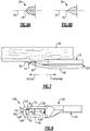
- the tip 28 tapers to a rounded point 48.
- the rounded point 48 is provided on a centerline 50 of the shaft 24.
- the centerline 50 of the shaft 24 in one example is also a centerline of the tendon stripper 20, and is contained within the common plane P.
- the tip 28 tapers to a sharp point 52 ( Figure 6B ). While the rounded point 48 is blunt (i.e., not sharp), the tip 28 still increases the ease of separating tendon from adjacent muscle tissue because the tip 28 is provided along the centerline 50.
- FIG 7 schematically illustrates the tendon stripper 20 in use.
- the hook 26 has captured a tendon 54.
- a user separates the tendon 54 from adjacent muscle tissue 56 by movement of the tendon stripper 20 in the distal direction.
- the arrangement of the hook 26 and tip 28 is such that the point (e.g., points 48, 52) of the tip 28 is provided at a junction between the tendon 54 and the muscle tissue 56.
- the tendon 54 is below the centerline 50 proximal of the tip 28, and the muscle tissue 56 is above the centerline 50 proximal of the tip 28.
- the hook 26 of the present disclosure is configured to maintain the position of the tip 28 at the junction between the tendon 54 and the muscle tissue 56, while also allowing for ease of movement of the tendon stripper 20 in the distal direction.
- Figure 8 is a side view of another example tendon stripper 120. To the extent not otherwise described or shown, the tendon stripper 120 corresponds to the tendon stripper 20 of Figures 1-7 , with like parts preappended with a "1.”
- the tendon stripper 120 includes a retention structure with a straight leading edge 158.
- the retention structure is a hook 126. Again, this disclosure is not limited to hooks and extends to other types of retention structures.
- the hook 126 in this example includes first and second linear portions 138, 140, which are substantially similar to the first and second linear portions 38, 40 of the hook 26.
- the first and second linear portions 138, 140 are connected by a connection section 160 having a first curved portion 162, a straight portion 164 providing the straight leading edge 158, and a second curved portion 166.
- the first curved portion 162 extends between the first linear portion 138 and the straight portion 164.
- the first curved portion 162 follows a radius R 2 of curvature.
- the radius R 2 extends from an origin O 2 between the first and second linear portions 138, 140, but substantially closer to the first linear portion 138 than the second linear portion 140.
- the first curved portion 162 bends 90° about the origin O 2 .
- the straight portion 164 in this example extends substantially perpendicular to the first and second linear portions 138, 140.
- the straight portion 164 provides the tendon stripper 120 with a straight leading edge 158, which facilitates movement of the tendon stripper 120 within a patient's body.
- the second curved portion 166 connects the straight portion 164 and the second linear portion 140.
- the second curved portion 164 is shaped similar to the first curved portion 162, and in particular follows a radius R 3 of curvature, which extends from an origin O 3 .
- the origin O 3 is between the first and second linear portions 138, 140, but is substantially closer to the second linear portion 140 than the first linear portion 138.
- the second curved portion 166 bends 90° about the origin O 3 .
- the straight portion 164 extends a distance D 5 between the first and second curved portions 162, 166.
- the distance D 5 is equal to the distance D 4 less the radiuses R 1 , R 2 .
- the entirety of the hook 126 is provided in a common plane in the same way as the hook 26.
- the hook 126 provides the tendon stripper 120 with similar benefits to the hook 26, including increasing the ease of capturing a tendon, increasing ease of use when the tendon stripper is held in various positions, maintaining tip position during cutting, etc. While two hook arrangements have been illustrated across Figures 1-8 , this disclosures extends to other hook arrangements.
Landscapes
- Health & Medical Sciences (AREA)
- Surgery (AREA)
- Life Sciences & Earth Sciences (AREA)
- Medical Informatics (AREA)
- Nuclear Medicine, Radiotherapy & Molecular Imaging (AREA)
- Engineering & Computer Science (AREA)
- Biomedical Technology (AREA)
- Heart & Thoracic Surgery (AREA)
- Molecular Biology (AREA)
- Animal Behavior & Ethology (AREA)
- General Health & Medical Sciences (AREA)
- Public Health (AREA)
- Veterinary Medicine (AREA)
- Rheumatology (AREA)
- Orthopedic Medicine & Surgery (AREA)
- Surgical Instruments (AREA)
Abstract
Description
- This disclosure relates to a tendon stripper for use in separating at least a portion of a tendon from adjacent muscle tissue.
- Tendon strippers are used to harvest tendons for use in orthopedic procedures. In one known procedure, a tendon stripper is used to harvest at least a portion of a hamstring. The harvested hamstring tendon may then be used in an anterior cruciate ligament (ACL) reconstruction surgery, for example. Tendons are also known to be harvested from other areas of the body, such as the wrist, and can used in other types of orthopedic procedures, such as ulna collateral ligament (UCL) reconstructions.
- This disclosure relates to a tendon stripper, which may be used to separate at least a portion of a tendon from adjacent muscle tissue. The harvested tendon can then be used in various orthopedic procedures, such as ACL and UCL reconstructions, to name a few examples.
- A tendon stripper according to an exemplary aspect of the present disclosure includes, inter alia, a shaft including a tip tapering to a point at the distal end of the shaft, and a retention structure moveable between an open position and a closed position to capture and retain a tendon relative to the tip. The tip arrangement preferably increases the ease of separating a tendon from adjacent muscle tissue.
- A tendon stripper according to another exemplary aspect of the present disclosure includes, inter alia, a shaft including a tip provided at a distal end of the shaft, and a retention structure moveable between an open position and a closed position, preferably to capture and retain a tendon relative to the tip. The retention structure is provided entirely in a common plane containing a centerline of the shaft. The retention structure arrangement preferably provides the retention structure with symmetry, which makes the tendon stripper easy to use on either side of a patient's body, and by either hand of the user.
- A method according to an exemplary aspect of the present disclosure includes, inter alia, capturing a tendon in a retention structure of a tendon stripper, and moving the tendon stripper distally to separate at least a portion of a tendon from adjacent muscle tissue. The tendon stripper includes a shaft with a tip at a distal end of the shaft. The tip tapers to a point, which increases the ease of separating tendon from adjacent muscle.
-
-
Figure 1 illustrates an example tendon stripper with a retention structure in a closed position. -
Figure 2 illustrates the example tendon stripper with the retention structure in an open position. -
Figure 3 is a side view of the tendon stripper ofFigures 1-2 with the retention structure in the open position, and illustrates the detail of the retention structure and a tip of the tendon stripper. -
Figure 4 is a perspective view of the tendon stripper ofFigures 1-2 , and illustrates the detail of the retention structure and the tip. -
Figure 5 is a side view of the tendon stripper ofFigures 1-2 with the retention structure in the closed position, and illustrates the detail of the retention structure and the tip. -
Figure 6A is a cross-sectional view taken alongline 6A-6A fromFigure 5 , and illustrates a first example tip configuration. -
Figure 6B is a cross-sectional view taken alongline 6B-6B fromFigure 5 , and illustrates a second example tip configuration -
Figure 7 illustrates the tendon stripper ofFigures 1-2 in use. -
Figure 8 is a side view of another example tendon stripper. In this example, the retention structure has a straight leading surface. - This disclosure relates to a tendon stripper, which may be used to separate one or more tendons from adjacent muscle tissue. A harvested tendon can then be used in various orthopedic procedures, such as ACL and UCL reconstructions, to name a few examples.
- A tendon stripper according to an exemplary aspect of the present disclosure includes, inter alia, a shaft including a tip tapering to a point at the distal end of the shaft, and a retention structure moveable between an open position and a closed position to capture and retain a tendon relative to the tip. The tip arrangement preferably increases the ease of separating a tendon from adjacent muscle tissue.
- In a further embodiment, the tip tapers to a rounded point.
- In a further embodiment, the tip tapers to a sharp point.
- In a further embodiment, the point is coincident with a centerline of the shaft.
- In a further embodiment, the retention structure is a hook.
- In a further embodiment, the hook is provided entirely in a common plane containing a centerline of the shaft.
- In a further embodiment, the tendon stripper includes a handle. The shaft projects distally from the handle, and the handle includes a trigger provided in the common plane. Further, movement of the trigger moves the hook between the open and closed positions.
- In a further embodiment, movement of the trigger in the distal direction moves the hook to the open position.
- A tendon stripper according to another exemplary aspect of the present disclosure includes, inter alia, a shaft including a tip provided at a distal end of the shaft, and a retention structure moveable between an open position and a closed position preferably to capture and retain a tendon relative to the tip. The retention structure is provided entirely in a common plane containing a centerline of the shaft. The retention structure arrangement provides the retention structure with symmetry, which makes the tendon stripper easy to use on either side of a patient's body, and by either hand of the user.
- In a further embodiment, the retention structure is a hook including a first linear portion, a second linear portion, and a curved portion connecting the first and second linear portions. The first and second linear portions are substantially parallel to one another along their respective lengths.
- In a further embodiment, the first linear portion is at least partially received within the shaft and mechanically coupled to a trigger provided in a handle. Further, the shaft projects distally from the handle, and movement of the trigger moves the hook between the open position and the closed position.
- In a further embodiment, the trigger is provided in the common plane.
- In a further embodiment, the second linear portion has a proximal end configured to be received in a socket adjacent the tip when the hook is in the closed position.
- In a further embodiment, the curved portion follows an arc defined by a circle having a center between the first and second linear portions. Further, the first and second linear portions are spaced-apart from one another by a distance substantially equal to a diameter of the circle along substantially their entire respective lengths.
- In a further embodiment, the curved portion makes substantially a 180° bend about the center to connect the first and second linear portions.
- In a further embodiment, the tip tapers to a point coincident with the centerline of the shaft.
- In a further embodiment, the retention structure includes one of a hook, a square, a loop, a corkscrew, and a slotted sleeve.
- In a further embodiment, the retention structure includes a straight leading edge.
- A method according to an exemplary aspect of the present disclosure includes, inter alia, capturing a tendon in a retention structure of a tendon stripper, and moving the tendon stripper distally to separate at least a portion of a tendon from adjacent muscle tissue. The tendon stripper includes a shaft with a tip at a distal end of the shaft. The tip tapers to a point, which preferably increases the ease of separating tendon from adjacent muscle.
- In a further embodiment, the point of the tip is provided at a junction between the tendon and the muscle tissue during the separating step, and the point of the tip is coincident with a centerline of the shaft.
-
Figure 1 illustrates anexample tendon stripper 20. Thetendon stripper 20 includes ahandle 22, ashaft 24, and a retention structure. In the figures, the retention structure is ahook 26. This disclosure is not limited to tendon strippers with hooks, however, and extends to other types of retention structures such as squares, loops, corkscrews, and slotted sleeves, to name a few examples. - The
shaft 24 projects from thehandle 22 in a distal direction. Thehook 26 is moveable relative to theshaft 24 between an open position (Figure 2 ) in which a tendon 54 (Figure 7 ) can be captured by thehook 26, and a closed position (Figure 1 ) in which the capturedtendon 54 is secured relative to atip 28 of the shaft. As will be explained below, thetip 28 is configured to separate thetendon 54 from adjacent muscle tissue 56 (Figure 7 ). - In this example, the
hook 26 is selectively moveable between the open and closed positions by movement of atrigger 30 provided on thehandle 22. In this example, thetrigger 30 is configured for movement by a user's (e.g., a surgeon's) thumb. Thetrigger 30 is moveable in the distal and proximal directions to move the hook between the open and closed positions, respectively. The "proximal" and "distal" directions are labeled across the figures for purposes of explanation only. In some examples, thetrigger 30 is moveable to intermediate positions between the open and closed positions to accommodate different tendon sizes, for example. Further, in one example, thetrigger 30 is mechanically biased to the closed position. - While in the disclosed embodiment the
hook 26 is moveable relative to theshaft 24, in other examples theshaft 24 could be moveable relative to thehook 26. In that case, theshaft 24 would be selectively moveable in response to movement of thetrigger 30. - The
trigger 30 in this example is provided on a superior, or top,surface 32 of thehandle 22. Thehandle 22 may also include a second trigger 34 (shown in phantom inFigure 1 ) on an inferior, or bottom,surface 36 of thehandle 22. Thefirst trigger 30 and the second trigger 34, if present, are both configured to selectively move thehook 26 between the open and closed positions. In one example, the second trigger 34 moves with thefirst trigger 30. Alternatively, the second trigger 34 could move independently of thefirst trigger 30. - The arrangement of the
hook 26 allows for increased ease of capturing a tendon within thehook 26. Further, thehook 26 andtip 28 arrangement provides for increased functionality of thetendon stripper 20. Namely, the arrangement allows thetendon stripper 20 to be easily used on both sides of a patient's body, and by either hand of a user (e.g., a surgeon). - With reference to
Figure 3 , in one example thehook 26 is substantially U-shaped. In particular, thehook 26 includes a firstlinear portion 38, a secondlinear portion 40, and acurved portion 42 between the first and secondlinear portions linear portions - In this example, the first
linear portion 38 has a length D1 greater than the length D2 of the secondlinear portion 40. Further, the firstlinear portion 38 is received at least partially inside theshaft 24, and is mechanically coupled to thetrigger 30. The firstlinear portion 38 may be directly coupled to thetrigger 30, or thetendon stripper 20 may include an intermediate actuator, such as a shaft or cable, configured to transmit force from thetrigger 30 to the firstlinear portion 38. - The proximal end 44 of the second
linear portion 40 is configured to be received in asocket 46 provided adjacent thetip 28. When in the open position, as shown inFigure 3 , a tendon can be captured within thehook 26 by virtue of the space between the proximal end 44 of the secondlinear portion 40 and thetip 28. - In this example, the
curved portion 42 follows an arc defined by a circle having a center at an origin O1 between the first and secondlinear portions curved portion 42 provides a semi-circle, and in this example makes a 180° bend about the origin O1 to connect the first and secondlinear portions linear portions linear portions hook 26. Further, thetip 28 spans the entire distance D4 between the first and secondlinear portions - With reference to
Figure 4 , thehook 26 is provided entirely in a common plane P, in one example, and thehook 26 is bisected by the common plane P. That is, the first and secondlinear portions curved portion 42 are entirely provided in a common plane P. The first and secondlinear portions curved portion 42 do not bend out of the common plane P in the side-to-side directions (e.g., in or out of the page, relative toFigure 4 ). In one example, the common plane P contains a centerline 50 (Figures 6A-6B ) bisecting thetendon stripper 20. This arrangement provides thehook 26 with symmetry, which makes thetendon stripper 20 easy to use on either side of a patient's body, and by either hand of the user. To this end, thetrigger 30 and the second trigger 34 (if present) are also provided in the common plane P such that thetriggers 30, 34 are easily accessed by the user when thetendon stripper 20 is held in various orientations. -
Figure 5 illustrates thehook 26 in a closed position, in which thehook 26 and thetip 28 enclose a space for receiving atendon 54. In one example, thetip 28 is provided along a centerline 50 (Figures 6A-6B ) of theshaft 24. Additionally, thetip 28 may taper to a point. Thetip 28 thus increases the ease of separating a tendon from adjacent muscle tissue. - In one example, illustrated in
Figure 6A , thetip 28 tapers to arounded point 48. Therounded point 48 is provided on acenterline 50 of theshaft 24. Thecenterline 50 of theshaft 24 in one example is also a centerline of thetendon stripper 20, and is contained within the common plane P. In another example, thetip 28 tapers to a sharp point 52 (Figure 6B ). While therounded point 48 is blunt (i.e., not sharp), thetip 28 still increases the ease of separating tendon from adjacent muscle tissue because thetip 28 is provided along thecenterline 50. -
Figure 7 schematically illustrates thetendon stripper 20 in use. InFigure 7 , thehook 26 has captured atendon 54. A user separates thetendon 54 fromadjacent muscle tissue 56 by movement of thetendon stripper 20 in the distal direction. As shown inFigure 7 , the arrangement of thehook 26 andtip 28 is such that the point (e.g., points 48, 52) of thetip 28 is provided at a junction between thetendon 54 and themuscle tissue 56. With reference to the orientation ofFigure 7 , thetendon 54 is below thecenterline 50 proximal of thetip 28, and themuscle tissue 56 is above thecenterline 50 proximal of thetip 28. Thehook 26 of the present disclosure is configured to maintain the position of thetip 28 at the junction between thetendon 54 and themuscle tissue 56, while also allowing for ease of movement of thetendon stripper 20 in the distal direction. -
Figure 8 is a side view of anotherexample tendon stripper 120. To the extent not otherwise described or shown, thetendon stripper 120 corresponds to thetendon stripper 20 ofFigures 1-7 , with like parts preappended with a "1." - In
Figure 8 , thetendon stripper 120 includes a retention structure with a straightleading edge 158. In this example, the retention structure is ahook 126. Again, this disclosure is not limited to hooks and extends to other types of retention structures. - The
hook 126 in this example includes first and secondlinear portions linear portions hook 26. In thehook 126, the first and secondlinear portions connection section 160 having a firstcurved portion 162, astraight portion 164 providing the straightleading edge 158, and a secondcurved portion 166. - In this example, the first
curved portion 162 extends between the firstlinear portion 138 and thestraight portion 164. The firstcurved portion 162 follows a radius R2 of curvature. The radius R2 extends from an origin O2 between the first and secondlinear portions linear portion 138 than the secondlinear portion 140. In this example, the firstcurved portion 162 bends 90° about the origin O2. - The
straight portion 164 in this example extends substantially perpendicular to the first and secondlinear portions straight portion 164 provides thetendon stripper 120 with a straightleading edge 158, which facilitates movement of thetendon stripper 120 within a patient's body. - The second
curved portion 166 connects thestraight portion 164 and the secondlinear portion 140. The secondcurved portion 164 is shaped similar to the firstcurved portion 162, and in particular follows a radius R3 of curvature, which extends from an origin O3. The origin O3 is between the first and secondlinear portions linear portion 140 than the firstlinear portion 138. In this example, the secondcurved portion 166 bends 90° about the origin O3. - In this example, the
straight portion 164 extends a distance D5 between the first and secondcurved portions hook 126 is provided in a common plane in the same way as thehook 26. Thehook 126 provides thetendon stripper 120 with similar benefits to thehook 26, including increasing the ease of capturing a tendon, increasing ease of use when the tendon stripper is held in various positions, maintaining tip position during cutting, etc. While two hook arrangements have been illustrated acrossFigures 1-8 , this disclosures extends to other hook arrangements. - It should be understood that terms such as "distal," "proximal," "superior," "inferior," etc., have been used herein for purposes of explanation, and should not be considered otherwise limiting. Terms such as "generally," "substantially," and "about" are not intended to be boundaryless terms, and should be interpreted consistent with the way one skilled in the art would interpret those terms.
- Although the different examples have the specific components shown in the illustrations, embodiments of this disclosure are not limited to those particular combinations. It is possible to use some of the components or features from one of the examples in combination with features or components from another one of the examples.
- One of ordinary skill in this art would understand that the above-described embodiments are exemplary and non-limiting. That is, modifications of this disclosure would come within the scope of the claims. Accordingly, the following claims should be studied to determine their true scope and content.
Claims (15)
- A tendon stripper (20), comprising:a shaft (24) including a tip (28) tapering to a point (48, 52) at the distal end of the shaft; anda retention structure (26, 126) moveable between an open position and a closed position to capture and retain a tendon (54) relative to the tip.
- The tendon stripper (20) according to claim 1,
characterized in, that
the tip (28) tapers to a rounded point (48) or to a sharp point (52). - The tendon stripper (20) according to any one of the previous claims,
characterized in, that
the point (48, 52) is coincident with a centerline (50) of the shaft. - The tendon stripper (20) according to any one of the previous claims,
characterized in, that
the retention structure is a hook (26, 126). - The tendon stripper (20) according to claim 4,
characterized in, that
the hook (26, 126) is provided entirely in a common plane (P) containing a centerline (50) of the shaft. - The tendon stripper (20) according to claim 5,
characterized in, that
the tendon stripper (20) further comprising a handle, the shaft projecting distally from the handle, wherein the handle includes a trigger provided in the common plane (P), and wherein movement of the trigger moves the hook (26, 126) between the open and closed positions. - The tendon stripper (20) according to claim 6,
characterized in, that
movement of the trigger in the distal direction moves the hook to the open position. - A tendon stripper (20), comprising:a shaft (24) including a tip (28) provided at a distal end of the shaft; anda retention structure (26, 126) moveable between an open position and a closed position to capture and retain a tendon (54) relative to the tip (28), wherein the retention structure (26, 126) is provided entirely in a common plane (P) containing a centerline (50) of the shaft.
- The tendon stripper (20) according to claim 8,
characterized in, that
the retention structure (26, 126) is a hook (26, 126) including a first linear portion (38, 138), a second linear portion (40, 140), and a curved portion (42) connecting the first (38, 138) and second (40, 140) linear portions, wherein the first and second linear portions are substantially parallel to one another along their respective lengths. - The tendon stripper (20) according to claim 9,
characterized in, that
the first linear portion (38, 138) is at least partially received within the shaft (24) and mechanically coupled to a trigger (30, 34) provided in a handle, the shaft projecting distally from the handle, wherein movement of the trigger (30, 34) moves the hook (26, 126) between the open position and the closed position. - The tendon stripper (20) according to claim 10,
characterized in, that
the trigger (30, 34) is provided in the common plane (P). - The tendon stripper (20) according to claim 10,
characterized in, that
the second linear portion (40, 140) has a proximal end configured to be received in a socket adjacent the tip (28) when the hook is in the closed position. - The tendon stripper (20) according to any one of claims 9 to 12,
characterized in, that
the curved portion (42) follows an arc defined by a circle having a center between the first (38, 138) and second (40, 140) linear portions, and wherein the first (38, 138) and second (40, 140) linear portions are spaced-apart from one another by a distance substantially equal to a diameter of the circle along substantially their entire respective lengths. - The tendon stripper (20) according to claim 13,
characterized in, that
the curved portion (42) makes substantially a 180° bend about the center to connect the first (38, 138) and second (40, 140) linear portions. - The tendon stripper (20) according to any one of claims 8 to 14,
characterized in, that
the tip (28) tapers to a point coincident with the centerline (50) of the shaft and/or the retention structure (26, 126) includes one of a hook (26), a square, a loop, a corkscrew, a slotted sleeve and a straight leading edge (158).
Applications Claiming Priority (1)
| Application Number | Priority Date | Filing Date | Title |
|---|---|---|---|
| US15/211,683 US20180014821A1 (en) | 2016-07-15 | 2016-07-15 | Tendon stripper |
Publications (2)
| Publication Number | Publication Date |
|---|---|
| EP3269311A1 true EP3269311A1 (en) | 2018-01-17 |
| EP3269311B1 EP3269311B1 (en) | 2020-12-02 |
Family
ID=59337522
Family Applications (1)
| Application Number | Title | Priority Date | Filing Date |
|---|---|---|---|
| EP17181054.2A Active EP3269311B1 (en) | 2016-07-15 | 2017-07-12 | Tendon stripper |
Country Status (2)
| Country | Link |
|---|---|
| US (1) | US20180014821A1 (en) |
| EP (1) | EP3269311B1 (en) |
Families Citing this family (4)
| Publication number | Priority date | Publication date | Assignee | Title |
|---|---|---|---|---|
| US20210282800A1 (en) * | 2018-07-27 | 2021-09-16 | Public University Corporation Nara Medical University | Tendon graft harvesting device |
| JP7158571B2 (en) * | 2018-09-13 | 2022-10-21 | メダクタ・インターナショナル・ソシエテ・アノニム | Tool for subcutaneous tendon cutting |
| US12167861B2 (en) | 2018-10-05 | 2024-12-17 | Smith & Nephew, Inc. | Tendon harvesting system |
| CN111904487A (en) * | 2020-07-16 | 2020-11-10 | 北京大学深圳医院 | tendon extractor |
Citations (3)
| Publication number | Priority date | Publication date | Assignee | Title |
|---|---|---|---|---|
| US6045561A (en) * | 1998-06-23 | 2000-04-04 | Orthopaedic Biosystems Ltd., Inc. | Surgical knot manipulator |
| US6110190A (en) * | 1996-03-20 | 2000-08-29 | Cardiothoracic Systems, Inc. | Surgical instrument for facilitating the detachment of an artery and the like |
| WO2006119238A2 (en) * | 2005-05-04 | 2006-11-09 | Lee Thomas H | Tendon stripper |
Family Cites Families (4)
| Publication number | Priority date | Publication date | Assignee | Title |
|---|---|---|---|---|
| US8808319B2 (en) * | 2007-07-27 | 2014-08-19 | Ethicon Endo-Surgery, Inc. | Surgical instruments |
| WO2013071938A1 (en) * | 2011-11-16 | 2013-05-23 | Coloplast A/S | Operation device especially intended for proceeding to an operation inside the body of a living being |
| WO2015009840A1 (en) * | 2013-07-16 | 2015-01-22 | Suture Ease, Inc. | Suture apparatus, system and method |
| CN107106195B (en) * | 2014-12-25 | 2019-08-23 | 奥林巴斯株式会社 | Medical Devices and Medical Systems |
-
2016
- 2016-07-15 US US15/211,683 patent/US20180014821A1/en not_active Abandoned
-
2017
- 2017-07-12 EP EP17181054.2A patent/EP3269311B1/en active Active
Patent Citations (3)
| Publication number | Priority date | Publication date | Assignee | Title |
|---|---|---|---|---|
| US6110190A (en) * | 1996-03-20 | 2000-08-29 | Cardiothoracic Systems, Inc. | Surgical instrument for facilitating the detachment of an artery and the like |
| US6045561A (en) * | 1998-06-23 | 2000-04-04 | Orthopaedic Biosystems Ltd., Inc. | Surgical knot manipulator |
| WO2006119238A2 (en) * | 2005-05-04 | 2006-11-09 | Lee Thomas H | Tendon stripper |
Also Published As
| Publication number | Publication date |
|---|---|
| EP3269311B1 (en) | 2020-12-02 |
| US20180014821A1 (en) | 2018-01-18 |
Similar Documents
| Publication | Publication Date | Title |
|---|---|---|
| US4813407A (en) | Sesamoid bone clamp | |
| US20180014821A1 (en) | Tendon stripper | |
| US4161951A (en) | Needle driver | |
| US7153321B2 (en) | Surgical forceps | |
| US20130012953A1 (en) | Orthopedic suture passer and method | |
| US20130245700A1 (en) | Cmc repair using suture-button construct | |
| US12070199B2 (en) | Surgical instrument for graft harvesting | |
| US6086596A (en) | Magnetically assisted surgical wiring and cabling passer devices | |
| EP0980673A3 (en) | Vessel isolating retractor cannula and method | |
| US20040231167A1 (en) | Fingertip suture-cutting apparatus | |
| US9545260B2 (en) | Minimally invasive device for surgical operations | |
| CN107536639B (en) | Method for fixing a plate to a fracture site of a bone using a removable insert | |
| US20120109145A1 (en) | Circumcision device | |
| US20140330307A1 (en) | Surgical Passer and Retrieval Device | |
| JP5804428B2 (en) | Incision surgery instrument | |
| EP3181059A1 (en) | Surgical device | |
| JP6531231B1 (en) | Transplant tendon collector | |
| CN203935218U (en) | Can beating type surgery tractor | |
| US6663654B1 (en) | Forceps with foreign body locator | |
| CN201888845U (en) | Orthopaedic minimally invasive steel wire introducer | |
| US7981125B1 (en) | Surgical knot pusher and cutter | |
| CN217488723U (en) | Titanium plate with belt loop | |
| KR101677261B1 (en) | Cutter of the femoral head of pet | |
| CN202458576U (en) | Tendon broken end pliers | |
| CN109009334B (en) | Orthopedic surgery stripping guide device |
Legal Events
| Date | Code | Title | Description |
|---|---|---|---|
| PUAI | Public reference made under article 153(3) epc to a published international application that has entered the european phase |
Free format text: ORIGINAL CODE: 0009012 |
|
| STAA | Information on the status of an ep patent application or granted ep patent |
Free format text: STATUS: THE APPLICATION HAS BEEN PUBLISHED |
|
| AK | Designated contracting states |
Kind code of ref document: A1 Designated state(s): AL AT BE BG CH CY CZ DE DK EE ES FI FR GB GR HR HU IE IS IT LI LT LU LV MC MK MT NL NO PL PT RO RS SE SI SK SM TR |
|
| AX | Request for extension of the european patent |
Extension state: BA ME |
|
| STAA | Information on the status of an ep patent application or granted ep patent |
Free format text: STATUS: REQUEST FOR EXAMINATION WAS MADE |
|
| 17P | Request for examination filed |
Effective date: 20180712 |
|
| RBV | Designated contracting states (corrected) |
Designated state(s): AL AT BE BG CH CY CZ DE DK EE ES FI FR GB GR HR HU IE IS IT LI LT LU LV MC MK MT NL NO PL PT RO RS SE SI SK SM TR |
|
| STAA | Information on the status of an ep patent application or granted ep patent |
Free format text: STATUS: EXAMINATION IS IN PROGRESS |
|
| 17Q | First examination report despatched |
Effective date: 20181207 |
|
| GRAP | Despatch of communication of intention to grant a patent |
Free format text: ORIGINAL CODE: EPIDOSNIGR1 |
|
| STAA | Information on the status of an ep patent application or granted ep patent |
Free format text: STATUS: GRANT OF PATENT IS INTENDED |
|
| RIC1 | Information provided on ipc code assigned before grant |
Ipc: A61B 17/00 20060101AFI20200527BHEP Ipc: A61B 17/32 20060101ALI20200527BHEP |
|
| INTG | Intention to grant announced |
Effective date: 20200617 |
|
| RIN1 | Information on inventor provided before grant (corrected) |
Inventor name: JOLLY, JACOB A. Inventor name: WEBER, ROBERT M. |
|
| GRAS | Grant fee paid |
Free format text: ORIGINAL CODE: EPIDOSNIGR3 |
|
| GRAA | (expected) grant |
Free format text: ORIGINAL CODE: 0009210 |
|
| STAA | Information on the status of an ep patent application or granted ep patent |
Free format text: STATUS: THE PATENT HAS BEEN GRANTED |
|
| AK | Designated contracting states |
Kind code of ref document: B1 Designated state(s): AL AT BE BG CH CY CZ DE DK EE ES FI FR GB GR HR HU IE IS IT LI LT LU LV MC MK MT NL NO PL PT RO RS SE SI SK SM TR |
|
| REG | Reference to a national code |
Ref country code: GB Ref legal event code: FG4D |
|
| REG | Reference to a national code |
Ref country code: AT Ref legal event code: REF Ref document number: 1340015 Country of ref document: AT Kind code of ref document: T Effective date: 20201215 Ref country code: CH Ref legal event code: EP |
|
| REG | Reference to a national code |
Ref country code: DE Ref legal event code: R096 Ref document number: 602017028648 Country of ref document: DE |
|
| REG | Reference to a national code |
Ref country code: IE Ref legal event code: FG4D |
|
| PG25 | Lapsed in a contracting state [announced via postgrant information from national office to epo] |
Ref country code: GR Free format text: LAPSE BECAUSE OF FAILURE TO SUBMIT A TRANSLATION OF THE DESCRIPTION OR TO PAY THE FEE WITHIN THE PRESCRIBED TIME-LIMIT Effective date: 20210303 Ref country code: FI Free format text: LAPSE BECAUSE OF FAILURE TO SUBMIT A TRANSLATION OF THE DESCRIPTION OR TO PAY THE FEE WITHIN THE PRESCRIBED TIME-LIMIT Effective date: 20201202 Ref country code: RS Free format text: LAPSE BECAUSE OF FAILURE TO SUBMIT A TRANSLATION OF THE DESCRIPTION OR TO PAY THE FEE WITHIN THE PRESCRIBED TIME-LIMIT Effective date: 20201202 Ref country code: NO Free format text: LAPSE BECAUSE OF FAILURE TO SUBMIT A TRANSLATION OF THE DESCRIPTION OR TO PAY THE FEE WITHIN THE PRESCRIBED TIME-LIMIT Effective date: 20210302 |
|
| REG | Reference to a national code |
Ref country code: NL Ref legal event code: MP Effective date: 20201202 |
|
| REG | Reference to a national code |
Ref country code: AT Ref legal event code: MK05 Ref document number: 1340015 Country of ref document: AT Kind code of ref document: T Effective date: 20201202 |
|
| PG25 | Lapsed in a contracting state [announced via postgrant information from national office to epo] |
Ref country code: BG Free format text: LAPSE BECAUSE OF FAILURE TO SUBMIT A TRANSLATION OF THE DESCRIPTION OR TO PAY THE FEE WITHIN THE PRESCRIBED TIME-LIMIT Effective date: 20210302 Ref country code: PL Free format text: LAPSE BECAUSE OF FAILURE TO SUBMIT A TRANSLATION OF THE DESCRIPTION OR TO PAY THE FEE WITHIN THE PRESCRIBED TIME-LIMIT Effective date: 20201202 Ref country code: LV Free format text: LAPSE BECAUSE OF FAILURE TO SUBMIT A TRANSLATION OF THE DESCRIPTION OR TO PAY THE FEE WITHIN THE PRESCRIBED TIME-LIMIT Effective date: 20201202 Ref country code: SE Free format text: LAPSE BECAUSE OF FAILURE TO SUBMIT A TRANSLATION OF THE DESCRIPTION OR TO PAY THE FEE WITHIN THE PRESCRIBED TIME-LIMIT Effective date: 20201202 |
|
| PG25 | Lapsed in a contracting state [announced via postgrant information from national office to epo] |
Ref country code: HR Free format text: LAPSE BECAUSE OF FAILURE TO SUBMIT A TRANSLATION OF THE DESCRIPTION OR TO PAY THE FEE WITHIN THE PRESCRIBED TIME-LIMIT Effective date: 20201202 Ref country code: NL Free format text: LAPSE BECAUSE OF FAILURE TO SUBMIT A TRANSLATION OF THE DESCRIPTION OR TO PAY THE FEE WITHIN THE PRESCRIBED TIME-LIMIT Effective date: 20201202 |
|
| REG | Reference to a national code |
Ref country code: LT Ref legal event code: MG9D |
|
| PG25 | Lapsed in a contracting state [announced via postgrant information from national office to epo] |
Ref country code: CZ Free format text: LAPSE BECAUSE OF FAILURE TO SUBMIT A TRANSLATION OF THE DESCRIPTION OR TO PAY THE FEE WITHIN THE PRESCRIBED TIME-LIMIT Effective date: 20201202 Ref country code: EE Free format text: LAPSE BECAUSE OF FAILURE TO SUBMIT A TRANSLATION OF THE DESCRIPTION OR TO PAY THE FEE WITHIN THE PRESCRIBED TIME-LIMIT Effective date: 20201202 Ref country code: LT Free format text: LAPSE BECAUSE OF FAILURE TO SUBMIT A TRANSLATION OF THE DESCRIPTION OR TO PAY THE FEE WITHIN THE PRESCRIBED TIME-LIMIT Effective date: 20201202 Ref country code: SM Free format text: LAPSE BECAUSE OF FAILURE TO SUBMIT A TRANSLATION OF THE DESCRIPTION OR TO PAY THE FEE WITHIN THE PRESCRIBED TIME-LIMIT Effective date: 20201202 Ref country code: SK Free format text: LAPSE BECAUSE OF FAILURE TO SUBMIT A TRANSLATION OF THE DESCRIPTION OR TO PAY THE FEE WITHIN THE PRESCRIBED TIME-LIMIT Effective date: 20201202 Ref country code: RO Free format text: LAPSE BECAUSE OF FAILURE TO SUBMIT A TRANSLATION OF THE DESCRIPTION OR TO PAY THE FEE WITHIN THE PRESCRIBED TIME-LIMIT Effective date: 20201202 Ref country code: PT Free format text: LAPSE BECAUSE OF FAILURE TO SUBMIT A TRANSLATION OF THE DESCRIPTION OR TO PAY THE FEE WITHIN THE PRESCRIBED TIME-LIMIT Effective date: 20210405 |
|
| PG25 | Lapsed in a contracting state [announced via postgrant information from national office to epo] |
Ref country code: AT Free format text: LAPSE BECAUSE OF FAILURE TO SUBMIT A TRANSLATION OF THE DESCRIPTION OR TO PAY THE FEE WITHIN THE PRESCRIBED TIME-LIMIT Effective date: 20201202 |
|
| REG | Reference to a national code |
Ref country code: DE Ref legal event code: R097 Ref document number: 602017028648 Country of ref document: DE |
|
| PG25 | Lapsed in a contracting state [announced via postgrant information from national office to epo] |
Ref country code: IS Free format text: LAPSE BECAUSE OF FAILURE TO SUBMIT A TRANSLATION OF THE DESCRIPTION OR TO PAY THE FEE WITHIN THE PRESCRIBED TIME-LIMIT Effective date: 20210402 |
|
| PLBE | No opposition filed within time limit |
Free format text: ORIGINAL CODE: 0009261 |
|
| STAA | Information on the status of an ep patent application or granted ep patent |
Free format text: STATUS: NO OPPOSITION FILED WITHIN TIME LIMIT |
|
| PG25 | Lapsed in a contracting state [announced via postgrant information from national office to epo] |
Ref country code: AL Free format text: LAPSE BECAUSE OF FAILURE TO SUBMIT A TRANSLATION OF THE DESCRIPTION OR TO PAY THE FEE WITHIN THE PRESCRIBED TIME-LIMIT Effective date: 20201202 Ref country code: IT Free format text: LAPSE BECAUSE OF FAILURE TO SUBMIT A TRANSLATION OF THE DESCRIPTION OR TO PAY THE FEE WITHIN THE PRESCRIBED TIME-LIMIT Effective date: 20201202 |
|
| 26N | No opposition filed |
Effective date: 20210903 |
|
| PG25 | Lapsed in a contracting state [announced via postgrant information from national office to epo] |
Ref country code: DK Free format text: LAPSE BECAUSE OF FAILURE TO SUBMIT A TRANSLATION OF THE DESCRIPTION OR TO PAY THE FEE WITHIN THE PRESCRIBED TIME-LIMIT Effective date: 20201202 Ref country code: SI Free format text: LAPSE BECAUSE OF FAILURE TO SUBMIT A TRANSLATION OF THE DESCRIPTION OR TO PAY THE FEE WITHIN THE PRESCRIBED TIME-LIMIT Effective date: 20201202 |
|
| PG25 | Lapsed in a contracting state [announced via postgrant information from national office to epo] |
Ref country code: ES Free format text: LAPSE BECAUSE OF FAILURE TO SUBMIT A TRANSLATION OF THE DESCRIPTION OR TO PAY THE FEE WITHIN THE PRESCRIBED TIME-LIMIT Effective date: 20201202 |
|
| REG | Reference to a national code |
Ref country code: CH Ref legal event code: PL |
|
| PG25 | Lapsed in a contracting state [announced via postgrant information from national office to epo] |
Ref country code: MC Free format text: LAPSE BECAUSE OF FAILURE TO SUBMIT A TRANSLATION OF THE DESCRIPTION OR TO PAY THE FEE WITHIN THE PRESCRIBED TIME-LIMIT Effective date: 20201202 |
|
| REG | Reference to a national code |
Ref country code: BE Ref legal event code: MM Effective date: 20210731 |
|
| PG25 | Lapsed in a contracting state [announced via postgrant information from national office to epo] |
Ref country code: LI Free format text: LAPSE BECAUSE OF NON-PAYMENT OF DUE FEES Effective date: 20210731 Ref country code: CH Free format text: LAPSE BECAUSE OF NON-PAYMENT OF DUE FEES Effective date: 20210731 |
|
| PG25 | Lapsed in a contracting state [announced via postgrant information from national office to epo] |
Ref country code: IS Free format text: LAPSE BECAUSE OF FAILURE TO SUBMIT A TRANSLATION OF THE DESCRIPTION OR TO PAY THE FEE WITHIN THE PRESCRIBED TIME-LIMIT Effective date: 20210402 Ref country code: LU Free format text: LAPSE BECAUSE OF NON-PAYMENT OF DUE FEES Effective date: 20210712 |
|
| PG25 | Lapsed in a contracting state [announced via postgrant information from national office to epo] |
Ref country code: IE Free format text: LAPSE BECAUSE OF NON-PAYMENT OF DUE FEES Effective date: 20210712 Ref country code: BE Free format text: LAPSE BECAUSE OF NON-PAYMENT OF DUE FEES Effective date: 20210731 |
|
| PG25 | Lapsed in a contracting state [announced via postgrant information from national office to epo] |
Ref country code: HU Free format text: LAPSE BECAUSE OF FAILURE TO SUBMIT A TRANSLATION OF THE DESCRIPTION OR TO PAY THE FEE WITHIN THE PRESCRIBED TIME-LIMIT; INVALID AB INITIO Effective date: 20170712 |
|
| PG25 | Lapsed in a contracting state [announced via postgrant information from national office to epo] |
Ref country code: CY Free format text: LAPSE BECAUSE OF FAILURE TO SUBMIT A TRANSLATION OF THE DESCRIPTION OR TO PAY THE FEE WITHIN THE PRESCRIBED TIME-LIMIT Effective date: 20201202 |
|
| PG25 | Lapsed in a contracting state [announced via postgrant information from national office to epo] |
Ref country code: MK Free format text: LAPSE BECAUSE OF FAILURE TO SUBMIT A TRANSLATION OF THE DESCRIPTION OR TO PAY THE FEE WITHIN THE PRESCRIBED TIME-LIMIT Effective date: 20201202 |
|
| PG25 | Lapsed in a contracting state [announced via postgrant information from national office to epo] |
Ref country code: MT Free format text: LAPSE BECAUSE OF FAILURE TO SUBMIT A TRANSLATION OF THE DESCRIPTION OR TO PAY THE FEE WITHIN THE PRESCRIBED TIME-LIMIT Effective date: 20201202 |
|
| PGFP | Annual fee paid to national office [announced via postgrant information from national office to epo] |
Ref country code: GB Payment date: 20250529 Year of fee payment: 9 |
|
| PGFP | Annual fee paid to national office [announced via postgrant information from national office to epo] |
Ref country code: FR Payment date: 20250610 Year of fee payment: 9 |
|
| PGFP | Annual fee paid to national office [announced via postgrant information from national office to epo] |
Ref country code: DE Payment date: 20250604 Year of fee payment: 9 |
|
| PG25 | Lapsed in a contracting state [announced via postgrant information from national office to epo] |
Ref country code: TR Free format text: LAPSE BECAUSE OF FAILURE TO SUBMIT A TRANSLATION OF THE DESCRIPTION OR TO PAY THE FEE WITHIN THE PRESCRIBED TIME-LIMIT Effective date: 20201202 |