EP3269310A1 - Loading fixture for use with endoscopic stitching device - Google Patents
Loading fixture for use with endoscopic stitching device Download PDFInfo
- Publication number
- EP3269310A1 EP3269310A1 EP17176570.4A EP17176570A EP3269310A1 EP 3269310 A1 EP3269310 A1 EP 3269310A1 EP 17176570 A EP17176570 A EP 17176570A EP 3269310 A1 EP3269310 A1 EP 3269310A1
- Authority
- EP
- European Patent Office
- Prior art keywords
- loading
- shuttle
- jaws
- stitching device
- needle
- Prior art date
- Legal status (The legal status is an assumption and is not a legal conclusion. Google has not performed a legal analysis and makes no representation as to the accuracy of the status listed.)
- Granted
Links
Images
Classifications
-
- A—HUMAN NECESSITIES
- A61—MEDICAL OR VETERINARY SCIENCE; HYGIENE
- A61B—DIAGNOSIS; SURGERY; IDENTIFICATION
- A61B17/00—Surgical instruments, devices or methods
- A61B17/04—Surgical instruments, devices or methods for suturing wounds; Holders or packages for needles or suture materials
- A61B17/0469—Suturing instruments for use in minimally invasive surgery, e.g. endoscopic surgery
-
- A—HUMAN NECESSITIES
- A61—MEDICAL OR VETERINARY SCIENCE; HYGIENE
- A61B—DIAGNOSIS; SURGERY; IDENTIFICATION
- A61B17/00—Surgical instruments, devices or methods
- A61B17/04—Surgical instruments, devices or methods for suturing wounds; Holders or packages for needles or suture materials
- A61B17/0491—Sewing machines for surgery
-
- A—HUMAN NECESSITIES
- A61—MEDICAL OR VETERINARY SCIENCE; HYGIENE
- A61B—DIAGNOSIS; SURGERY; IDENTIFICATION
- A61B17/00—Surgical instruments, devices or methods
- A61B17/04—Surgical instruments, devices or methods for suturing wounds; Holders or packages for needles or suture materials
- A61B17/06—Needles ; Sutures; Needle-suture combinations; Holders or packages for needles or suture materials
- A61B17/06066—Needles, e.g. needle tip configurations
-
- A—HUMAN NECESSITIES
- A61—MEDICAL OR VETERINARY SCIENCE; HYGIENE
- A61B—DIAGNOSIS; SURGERY; IDENTIFICATION
- A61B17/00—Surgical instruments, devices or methods
- A61B17/04—Surgical instruments, devices or methods for suturing wounds; Holders or packages for needles or suture materials
- A61B17/06—Needles ; Sutures; Needle-suture combinations; Holders or packages for needles or suture materials
- A61B17/06114—Packages or dispensers for needles or sutures
-
- A—HUMAN NECESSITIES
- A61—MEDICAL OR VETERINARY SCIENCE; HYGIENE
- A61B—DIAGNOSIS; SURGERY; IDENTIFICATION
- A61B17/00—Surgical instruments, devices or methods
- A61B17/04—Surgical instruments, devices or methods for suturing wounds; Holders or packages for needles or suture materials
- A61B17/06—Needles ; Sutures; Needle-suture combinations; Holders or packages for needles or suture materials
- A61B17/06166—Sutures
-
- A—HUMAN NECESSITIES
- A61—MEDICAL OR VETERINARY SCIENCE; HYGIENE
- A61B—DIAGNOSIS; SURGERY; IDENTIFICATION
- A61B17/00—Surgical instruments, devices or methods
- A61B17/04—Surgical instruments, devices or methods for suturing wounds; Holders or packages for needles or suture materials
- A61B17/06—Needles ; Sutures; Needle-suture combinations; Holders or packages for needles or suture materials
- A61B17/062—Needle manipulators
- A61B17/0625—Needle manipulators the needle being specially adapted to interact with the manipulator, e.g. being ridged to snap fit in a hole of the manipulator
-
- A—HUMAN NECESSITIES
- A61—MEDICAL OR VETERINARY SCIENCE; HYGIENE
- A61B—DIAGNOSIS; SURGERY; IDENTIFICATION
- A61B17/00—Surgical instruments, devices or methods
- A61B17/04—Surgical instruments, devices or methods for suturing wounds; Holders or packages for needles or suture materials
- A61B17/0482—Needle or suture guides
-
- A—HUMAN NECESSITIES
- A61—MEDICAL OR VETERINARY SCIENCE; HYGIENE
- A61B—DIAGNOSIS; SURGERY; IDENTIFICATION
- A61B17/00—Surgical instruments, devices or methods
- A61B2017/00526—Methods of manufacturing
- A61B2017/0053—Loading magazines or sutures into applying tools
-
- A—HUMAN NECESSITIES
- A61—MEDICAL OR VETERINARY SCIENCE; HYGIENE
- A61B—DIAGNOSIS; SURGERY; IDENTIFICATION
- A61B17/00—Surgical instruments, devices or methods
- A61B17/04—Surgical instruments, devices or methods for suturing wounds; Holders or packages for needles or suture materials
- A61B17/0469—Suturing instruments for use in minimally invasive surgery, e.g. endoscopic surgery
- A61B2017/047—Suturing instruments for use in minimally invasive surgery, e.g. endoscopic surgery having at least one proximally pointing needle located at the distal end of the instrument, e.g. for suturing trocar puncture wounds starting from inside the body
-
- A—HUMAN NECESSITIES
- A61—MEDICAL OR VETERINARY SCIENCE; HYGIENE
- A61B—DIAGNOSIS; SURGERY; IDENTIFICATION
- A61B17/00—Surgical instruments, devices or methods
- A61B17/04—Surgical instruments, devices or methods for suturing wounds; Holders or packages for needles or suture materials
- A61B17/06—Needles ; Sutures; Needle-suture combinations; Holders or packages for needles or suture materials
- A61B17/06004—Means for attaching suture to needle
- A61B2017/06047—Means for attaching suture to needle located at the middle of the needle
-
- A—HUMAN NECESSITIES
- A61—MEDICAL OR VETERINARY SCIENCE; HYGIENE
- A61B—DIAGNOSIS; SURGERY; IDENTIFICATION
- A61B17/00—Surgical instruments, devices or methods
- A61B17/04—Surgical instruments, devices or methods for suturing wounds; Holders or packages for needles or suture materials
- A61B17/06—Needles ; Sutures; Needle-suture combinations; Holders or packages for needles or suture materials
- A61B17/06066—Needles, e.g. needle tip configurations
- A61B2017/0609—Needles, e.g. needle tip configurations having sharp tips at both ends, e.g. shuttle needle alternately retained and released by first and second facing jaws of a suturing instrument
-
- A—HUMAN NECESSITIES
- A61—MEDICAL OR VETERINARY SCIENCE; HYGIENE
- A61B—DIAGNOSIS; SURGERY; IDENTIFICATION
- A61B17/00—Surgical instruments, devices or methods
- A61B17/04—Surgical instruments, devices or methods for suturing wounds; Holders or packages for needles or suture materials
- A61B17/06—Needles ; Sutures; Needle-suture combinations; Holders or packages for needles or suture materials
- A61B17/06166—Sutures
- A61B2017/06176—Sutures with protrusions, e.g. barbs
-
- A—HUMAN NECESSITIES
- A61—MEDICAL OR VETERINARY SCIENCE; HYGIENE
- A61B—DIAGNOSIS; SURGERY; IDENTIFICATION
- A61B17/00—Surgical instruments, devices or methods
- A61B17/28—Surgical forceps
- A61B17/29—Forceps for use in minimally invasive surgery
- A61B2017/2926—Details of heads or jaws
Definitions
- the present disclosure relates to devices for use with suturing or stitching and, more particularly, to a loading fixture for positioning a surgical needle on devices for endoscopic suturing and/or stitching through an access tube or the like.
- endoscopic surgery involves incising through body walls.
- trocars are utilized for creating the incisions through which the endoscopic surgery is performed.
- Trocar tubes or cannula devices are extended into and left in place in the abdominal wall to provide access for endoscopic surgical tools.
- a camera or endoscope is inserted through a relatively large diameter trocar tube which is generally located at the naval incision, and permits the visual inspection and magnification of the body cavity.
- the surgeon can then perform diagnostic and therapeutic procedures at the surgical site with the aid of specialized instrumentation, such as, forceps, cutters, applicators, and the like which are designed to fit through additional cannulas.
- the present disclosure describes a loading fixture that demonstrates a practical approach to meeting the performance requirements and overcoming usability challenges associated with precisely positioning a surgical needle for receipt by a surgical suturing device.
- a loading fixture for use with an endoscopic stitching device.
- the loading fixture includes a needle and a loading portion configured to receive jaws of the endoscopic stitching device.
- the loading portion includes a shuttle, guides, and a biasing member.
- the shuttle is configured to detachably support the needle thereon.
- the shuttle is transversely slidable such that the needle supported on the shuttle engages at least one of the jaws of the endoscopic stitching device.
- the guides are configured to position the jaws of the endoscopic stitching device therebetween.
- the biasing member is configured to bias the shuttle toward one of the guides.
- the loading portion may define a slot configured to slidably receive the shuttle.
- the slot of the loading portion may define an arc.
- the guides may be disposed on opposing peripheral sides of the loading portion.
- One of the guides may be L-shaped.
- the loading fixture may further include a neck portion configured to securely engage a support member of a tool assembly of the endoscopic stitching device.
- the neck portion may include a support including a U-shaped cross-section configured to receive the support member of the tool assembly.
- the loading portion may define a spooling portion configured to retain a suture thereon.
- the spooling portion may be disposed on a first surface of the loading portion and the shuttle may be disposed on a second surface of the loading portion, wherein the first surface is opposite of the second surface.
- the loading fixture may further include a grip portion extending distally from the loading portion.
- the grip portion and the loading portion may define a slot configured to receive the suture therethrough.
- an endoscopic stitching device assembly includes a tool assembly and a loading fixture.
- the tool assembly includes a support member, first and second jaws operatively coupled with the support member, and first and second needle receiving blades slidably disposed in the respective first and second jaws.
- the first and second jaws are configured to pivot between open and closed positions.
- the loading fixture is configured to be detachably secured with the tool assembly.
- the loading fixture includes a needle and a loading portion configured to receive the first and second jaws of the tool assembly.
- the loading portion includes a shuttle configured to detachably support the needle thereon, guides to position the first and second jaws of the tool assembly therebetween, and a biasing member configured to bias the shuttle toward one of the guides.
- the shuttle is transversely slidable such that the needle supported on the shuttle engages at least one of the first or second needle receiving blades of the tool assembly.
- the loading portion may further include a central guide portion configured to limit distal displacement of the first and second jaws in the closed position.
- distal as is conventional, will refer to that portion of the instrument, apparatus, device or component thereof which is farther from the user while, the term “proximal,” will refer to that portion of the instrument, apparatus, device or component thereof which is closer to the user.
- proximal will refer to that portion of the instrument, apparatus, device or component thereof which is closer to the user.
- Stitching device 1000 is adapted to be particularly useful in endoscopic or laparoscopic procedures, wherein an endoscopic portion of stitching device 1000 such as, e.g., a tool assembly 120, is insertable into an operative site, via a cannula assembly or the like (not shown).
- Stitching device 1000 includes a handle assembly 100, an elongate shaft assembly 170 extending distally from handle assembly 100, and tool assembly 120 detachably supported on a distal end of elongate shaft assembly 170.
- Such a configuration facilitates, e.g., sterilization of stitching device 1000 and loading of needle on tool assembly 120.
- tool assembly 120 includes a support member 122 and jaws 130, 132 pivotably mounted on support member 122 by means of a jaw pivot pin 134.
- an axial rod 156 has a camming pin 138 mounted at a distal end 156a thereof.
- Camming pin 138 rides in angled camming slots 130c, 132c defined in respective jaws 130, 132 such that axial or longitudinal movement of axial rod 156 causes jaws 130, 132 to be cammed between the open and closed positions.
- Tool assembly 120 further includes a pair of needle engaging members or blades 150, 152 which are slidably supported within support member 122.
- Each blade 150, 152 includes a distal end 150a, 152a slidably extending into blade receiving channels 130d, 132d of respective jaws 130, 132.
- Channels 130d, 132d are dimensioned to at least partially intersect respective needle recesses 130a, 132a.
- Suture 2080 is connected to needle 104.
- Suture 2080 may include a plurality of barbs oriented to resist movement in a direction opposite to the direction of travel.
- handle assembly 100 includes a pair of handles 110 pivotably secured to housing 102. Handles 110 are operatively coupled to axial rod 156 such that when handles 110 are squeezed, axial rod 156 is displaced proximally.
- Axial rod 156 may be provided with, e.g., a biasing member (not shown), in the form of a return spring, to bias axial rod 156 to an initial position.
- Axial rod 156 is operatively coupled to jaws 130, 132 of tool assembly 120, such that axial displacement of axial rod 156 transitions jaws 130, 132 between the open and closed positions.
- handle assembly 100 further includes a lever 182 pivotably supported in housing 102 and extending transversely from housing 102.
- Lever 182 is operatively coupled to blades 150, 152 ( FIG. 2 ) of tool assembly 120.
- Lever 182 may be pivoted to cause reciprocating axial displacement of blades 150, 152 to enable swapping of needle 104 between jaws 130, 132.
- handle assembly 100 further includes a slider 119 ( FIG. 1 ) operatively coupled with lever 182 to slide lever 182 distally to transition handle assembly 100 to a reload mode.
- both blades 150, 152 FIG. 2
- notches (not shown) formed in respective blades 150, 152 are aligned with or in registration with respective needle recesses 130a, 132a defined in respective jaws 130, 132.
- needle 104 FIG. 1
- Loading fixture 2000 is configured to secure tool assembly 120 thereon to facilitate loading of needle 104 on jaws 130, 132.
- Loading fixture 2000 defines a longitudinal axis "Y-Y" and includes a body portion 2010 and a grip portion 2050.
- Grip portion 2050 may be textured, e.g., ridges, to improve gripping thereof by a user.
- Body portion 2010 and grip portion 2050 may be integrally formed as a single construct.
- Body portion 2010 includes a neck portion 2012 and a loading portion 2030.
- Neck portion 2012 is configured to secure support member 122 ( FIG. 2 ) of tool assembly 120 thereon.
- neck portion 2012 includes a support 2014 including a U-shaped arcuate portion 2014a configured to receive and align support member 122 of tool assembly 120 thereon.
- Support 2014 may include a boss 2016 configured to be received in a bore (not shown) defined in support member 122 to further facilitate alignment of support member 122 of tool assembly 120 with support 2014.
- Loading portion 2030 extends distally outward from neck portion 2012.
- Loading portion 2030 includes peripheral guides 2032, 2034 configured to position jaws 130, 132 of tool assembly 120 therebetween.
- Loading portion 2030 further includes a central guide 2036 positioned to be interposed between jaws 130, 132 of tool assembly 120 to limit distal displacement of jaws 130, 132 when jaws 130, 132 are in the closed position.
- at least one of peripheral guides 2032, 2034 may include a distal portion 2034a to limit distal displacement of jaws 130, 132 of tool assembly 120 when jaws 130, 132 are in the open position.
- Loading portion 2030 further defines a slot 2038 defining an arc between peripheral guides 2032, 2034. Slot 2038 is configured to slidably receive a shuttle 2040 therein. Shuttle 2040 defines a slit 2040a configured to support needle 104. Loading portion 2030 further includes a biasing member 2044 within slot 2038 thereof to bias shuttle 2040 toward one of peripheral guides 2032, 2034.
- Grip portion 2050 extends distally from loading portion 2030 of body portion 2010. Grip portion 2050 defines a bore 2052 extending therethrough and a slot 2054 in communication with bore 2052. Bore 2052 and slot 2054 are configured to receive suture 2080 connected to needle 104.
- body portion 2010 includes a spooling portion 2060.
- Spooling portion 2060 defines a recess 2062 and includes a winding portion 2064 to wind suture 2080 thereon.
- stitching device 1000 is first transitioned to the reload mode by sliding slider 119 ( FIG. 1 ) distally such that both blades 150, 152 ( FIG. 2 ) are in the distal-most position.
- notches (not shown) formed in respective blades 150, 152 are aligned with or in registration with respective needle recesses 130a, 132a defined in respective jaws 130, 132.
- needle 104 FIG. 2
- needle 104 may be positioned or loaded into a selected one needle recess 130a, 132a of jaws 130, 132.
- support member 122 of tool assembly 120 is aligned with body portion 2010 of loading fixture 2000 and received in support 2014 such that boss 2016 of support 2014 is received in the bore (not shown) defined in support member 122 of tool assembly 120.
- jaw 132 engages peripheral guide 2034 and needle recess 130a of jaw 130 is aligned with needle 104 disposed on shuttle 2040.
- handles 110 FIG. 1
- needle 104 is loaded or at least partially inserted into needle recesses 130a, 132a of jaws 130, 132, the notches (notches) of blades 150, 152 are in registration with respective grooves 104a of needle 104.
- lever 182 is actuated or rotated so that only one blade 150, 152 is moved into engagement with needle 104 ( FIG. 2 ) to hold needle 104, and the other blade 150, 152 is disengaged from needle 104.
- handles 110 may be released, thereby moving axial rod 156 distally to open jaws 130, 132.
- jaws 130, 132 With jaws 130, 132 in the open position and needle 104 loaded and held in jaw 130 or 132, jaws 130, 132 may be positioned about or over a target tissue and handles 110 may be actuated to approximate jaws 130, 132. As jaws 130, 132 are approximated, the exposed end of needle 104 is penetrated through the target tissue and enters opposed jaw 130 or 132. With needle 104 in opposed jaw 130 or 132, lever 182 is once again actuated or rotated so that blades 150, 152 are reversed. In so doing, needle 104 is swapped from one blade 150 or 152 to the other blade 150 or 152, and thus, loaded or held in the other jaw 130 or 132.
- handles 110 may be released to thereby open jaws 130, 132 and draw needle 104 through the target tissue. In so doing, suture 2080 is also drawn through the tissue. The process is repeated, passing needle 104 between jaws 130, 132 and drawing suture 2080 through the target tissue, thereby suturing the target tissue as needed or desired.
- spooling portion 2060 may be disposed on the same surface as shuttle 2040.
- spooling portion 2060 may be disposed on grip portion 2050. It is to be understood, therefore, that the disclosure is not limited to those precise embodiments, and that various other changes and modifications may be effected therein by one skilled in the art without departing from the scope or spirit of the disclosure.
Landscapes
- Health & Medical Sciences (AREA)
- Surgery (AREA)
- Life Sciences & Earth Sciences (AREA)
- Biomedical Technology (AREA)
- Nuclear Medicine, Radiotherapy & Molecular Imaging (AREA)
- Engineering & Computer Science (AREA)
- Heart & Thoracic Surgery (AREA)
- Medical Informatics (AREA)
- Molecular Biology (AREA)
- Animal Behavior & Ethology (AREA)
- General Health & Medical Sciences (AREA)
- Public Health (AREA)
- Veterinary Medicine (AREA)
- Dentistry (AREA)
- Surgical Instruments (AREA)
Abstract
Description
- This application claims the benefit of and priority to
U.S. Provisional Patent Application No. 62/352,035 filed June 20, 2016 - The present disclosure relates to devices for use with suturing or stitching and, more particularly, to a loading fixture for positioning a surgical needle on devices for endoscopic suturing and/or stitching through an access tube or the like.
- One of the advances in recent years to reduce the invasiveness of surgical procedures is endoscopic surgery. Generally, endoscopic surgery involves incising through body walls. Typically, trocars are utilized for creating the incisions through which the endoscopic surgery is performed. Trocar tubes or cannula devices are extended into and left in place in the abdominal wall to provide access for endoscopic surgical tools. A camera or endoscope is inserted through a relatively large diameter trocar tube which is generally located at the naval incision, and permits the visual inspection and magnification of the body cavity. The surgeon can then perform diagnostic and therapeutic procedures at the surgical site with the aid of specialized instrumentation, such as, forceps, cutters, applicators, and the like which are designed to fit through additional cannulas.
- In many surgical procedures, including those involved in endoscopic surgery, it is often necessary to suture bodily organs or tissue. In such surgical procedures, it is necessary to manipulate a surgical needle, having a length of suture material attached thereto, with a surgical suturing device. Therefore, a need exists for simple and effective devices capable of precisely positioning a surgical needle for receipt by a surgical suturing device.
- The present disclosure describes a loading fixture that demonstrates a practical approach to meeting the performance requirements and overcoming usability challenges associated with precisely positioning a surgical needle for receipt by a surgical suturing device. In accordance with an embodiment of the present disclosure, there is provided a loading fixture for use with an endoscopic stitching device. The loading fixture includes a needle and a loading portion configured to receive jaws of the endoscopic stitching device. The loading portion includes a shuttle, guides, and a biasing member. The shuttle is configured to detachably support the needle thereon. The shuttle is transversely slidable such that the needle supported on the shuttle engages at least one of the jaws of the endoscopic stitching device. The guides are configured to position the jaws of the endoscopic stitching device therebetween. The biasing member is configured to bias the shuttle toward one of the guides.
- In an embodiment, the loading portion may define a slot configured to slidably receive the shuttle. The slot of the loading portion may define an arc.
- In another embodiment, the guides may be disposed on opposing peripheral sides of the loading portion. One of the guides may be L-shaped.
- In yet another embodiment, the loading fixture may further include a neck portion configured to securely engage a support member of a tool assembly of the endoscopic stitching device. The neck portion may include a support including a U-shaped cross-section configured to receive the support member of the tool assembly.
- In still another embodiment, the loading portion may define a spooling portion configured to retain a suture thereon. The spooling portion may be disposed on a first surface of the loading portion and the shuttle may be disposed on a second surface of the loading portion, wherein the first surface is opposite of the second surface.
- In still yet another embodiment, the loading fixture may further include a grip portion extending distally from the loading portion. The grip portion and the loading portion may define a slot configured to receive the suture therethrough.
- In accordance with another embodiment of the present disclosure, there is provided an endoscopic stitching device assembly. The endoscopic stitching device assembly includes a tool assembly and a loading fixture. The tool assembly includes a support member, first and second jaws operatively coupled with the support member, and first and second needle receiving blades slidably disposed in the respective first and second jaws. The first and second jaws are configured to pivot between open and closed positions.
- In accordance with this embodiment, the loading fixture is configured to be detachably secured with the tool assembly. The loading fixture includes a needle and a loading portion configured to receive the first and second jaws of the tool assembly. The loading portion includes a shuttle configured to detachably support the needle thereon, guides to position the first and second jaws of the tool assembly therebetween, and a biasing member configured to bias the shuttle toward one of the guides. The shuttle is transversely slidable such that the needle supported on the shuttle engages at least one of the first or second needle receiving blades of the tool assembly.
- In an embodiment, the loading portion may further include a central guide portion configured to limit distal displacement of the first and second jaws in the closed position.
- The foregoing objects, features and advantages of the disclosure will become more apparent from a reading of the following description in connection with the accompanying drawings, in which:
-
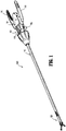
FIG. 1 is a perspective view of a stitching device for use with a loading fixture in accordance with an embodiment of the present disclosure; -
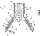
FIG. 2 is a partial cross-sectional view of a tool assembly of the stitching device ofFIG. 1 ; -
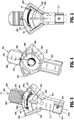
FIG. 3 is a top perspective view of the loading fixture in accordance with an embodiment of the present disclosure; -
FIG. 4 is a bottom perspective view of the loading fixture ofFIG. 3 ; and -
FIG. 5 is a top view of the loading fixture ofFIG. 3 , illustrating use with a tool assembly of the stitching device ofFIG. 1 shown in phantom. - Embodiments of the present disclosure will now be described in detail with reference to the drawings, in which like reference numerals designate identical or corresponding elements in each of the several views. As used herein, the term "distal," as is conventional, will refer to that portion of the instrument, apparatus, device or component thereof which is farther from the user while, the term "proximal," will refer to that portion of the instrument, apparatus, device or component thereof which is closer to the user. In the following description, well-known functions or constructions are not described in detail to avoid obscuring the present disclosure in unnecessary detail.
- With reference to
FIG. 1 , an embodiment of the present disclosure is generally shown as astitching device 1000.Stitching device 1000 is adapted to be particularly useful in endoscopic or laparoscopic procedures, wherein an endoscopic portion ofstitching device 1000 such as, e.g., atool assembly 120, is insertable into an operative site, via a cannula assembly or the like (not shown).Stitching device 1000 includes ahandle assembly 100, anelongate shaft assembly 170 extending distally fromhandle assembly 100, andtool assembly 120 detachably supported on a distal end ofelongate shaft assembly 170. Such a configuration facilitates, e.g., sterilization ofstitching device 1000 and loading of needle ontool assembly 120. - With reference to
FIGS. 1 and2 ,tool assembly 120 includes asupport member 122 andjaws support member 122 by means of ajaw pivot pin 134. To movejaws axial rod 156 has acamming pin 138 mounted at adistal end 156a thereof.Camming pin 138 rides inangled camming slots respective jaws axial rod 156 causesjaws -
Tool assembly 120 further includes a pair of needle engaging members orblades support member 122. Eachblade distal end blade receiving channels respective jaws Channels respective needle recesses blade respective channel distal end blade groove 104a formed inneedle 104 when at least a portion ofneedle 104 is received withinrespective needle recesses - With brief reference to
FIG. 4 , asuture 2080 is connected toneedle 104.Suture 2080 may include a plurality of barbs oriented to resist movement in a direction opposite to the direction of travel. - With continued reference to
FIGS. 1 and2 , handleassembly 100 includes a pair ofhandles 110 pivotably secured tohousing 102.Handles 110 are operatively coupled toaxial rod 156 such that when handles 110 are squeezed,axial rod 156 is displaced proximally.Axial rod 156 may be provided with, e.g., a biasing member (not shown), in the form of a return spring, to biasaxial rod 156 to an initial position.Axial rod 156 is operatively coupled tojaws tool assembly 120, such that axial displacement ofaxial rod 156transitions jaws - With particular reference to
FIG. 1 , handleassembly 100 further includes alever 182 pivotably supported inhousing 102 and extending transversely fromhousing 102.Lever 182 is operatively coupled toblades 150, 152 (FIG. 2 ) oftool assembly 120.Lever 182 may be pivoted to cause reciprocating axial displacement ofblades needle 104 betweenjaws - With continued reference to
FIG. 1 , handleassembly 100 further includes a slider 119 (FIG. 1 ) operatively coupled withlever 182 to slidelever 182 distally to transitionhandle assembly 100 to a reload mode. In the reload mode, bothblades 150, 152 (FIG. 2 ) are in a distal-most position. In this manner, notches (not shown) formed inrespective blades respective needle recesses respective jaws blades respective needle recesses respective jaws FIG. 2 ) may be positioned or loaded into a selected oneneedle recess jaws U.S. Patent No. 8,628,545 , entitled "Endoscopic Stitching Devices," the entire content of which is incorporated herein by reference, for a detailed discussed of the construction and operation of a handle assembly and a tool assembly. - With reference now to
FIGS. 3 and 4 , there is provided aloading fixture 2000 in accordance with an embodiment of the present disclosure.Loading fixture 2000 is configured to securetool assembly 120 thereon to facilitate loading ofneedle 104 onjaws Loading fixture 2000 defines a longitudinal axis "Y-Y" and includes abody portion 2010 and agrip portion 2050.Grip portion 2050 may be textured, e.g., ridges, to improve gripping thereof by a user.Body portion 2010 andgrip portion 2050 may be integrally formed as a single construct.Body portion 2010 includes aneck portion 2012 and aloading portion 2030.Neck portion 2012 is configured to secure support member 122 (FIG. 2 ) oftool assembly 120 thereon. - With particular reference to
FIG. 3 ,neck portion 2012 includes asupport 2014 including a U-shapedarcuate portion 2014a configured to receive and alignsupport member 122 oftool assembly 120 thereon.Support 2014 may include aboss 2016 configured to be received in a bore (not shown) defined insupport member 122 to further facilitate alignment ofsupport member 122 oftool assembly 120 withsupport 2014. -
Loading portion 2030 extends distally outward fromneck portion 2012.Loading portion 2030 includesperipheral guides jaws tool assembly 120 therebetween.Loading portion 2030 further includes acentral guide 2036 positioned to be interposed betweenjaws tool assembly 120 to limit distal displacement ofjaws jaws peripheral guides distal portion 2034a to limit distal displacement ofjaws tool assembly 120 whenjaws -
Loading portion 2030 further defines aslot 2038 defining an arc betweenperipheral guides Slot 2038 is configured to slidably receive ashuttle 2040 therein.Shuttle 2040 defines aslit 2040a configured to supportneedle 104.Loading portion 2030 further includes a biasingmember 2044 withinslot 2038 thereof tobias shuttle 2040 toward one ofperipheral guides -
Grip portion 2050 extends distally from loadingportion 2030 ofbody portion 2010.Grip portion 2050 defines abore 2052 extending therethrough and aslot 2054 in communication withbore 2052.Bore 2052 andslot 2054 are configured to receivesuture 2080 connected toneedle 104. - As illustrated in
FIG. 4 , on an opposingside 2010a ofbody portion 2010,body portion 2010 includes a spoolingportion 2060.Spooling portion 2060 defines arecess 2062 and includes a windingportion 2064 to windsuture 2080 thereon. - With reference now to
FIG. 5 , in use,stitching device 1000 is first transitioned to the reload mode by sliding slider 119 (FIG. 1 ) distally such that bothblades 150, 152 (FIG. 2 ) are in the distal-most position. In this manner, notches (not shown) formed inrespective blades respective needle recesses respective jaws blades respective needle recesses respective jaws FIG. 2 ) may be positioned or loaded into a selected oneneedle recess jaws - At this time,
support member 122 oftool assembly 120 is aligned withbody portion 2010 ofloading fixture 2000 and received insupport 2014 such thatboss 2016 ofsupport 2014 is received in the bore (not shown) defined insupport member 122 oftool assembly 120. In this manner,jaw 132 engagesperipheral guide 2034 andneedle recess 130a ofjaw 130 is aligned withneedle 104 disposed onshuttle 2040. At this time, handles 110 (FIG. 1 ) may be squeezed to closejaws needle 104 is loaded or at least partially inserted intoneedle recesses jaws blades respective grooves 104a ofneedle 104. Withneedle 104 positioned such that the notches ofblades needle recesses 130a, 130b,lever 182 is actuated or rotated so that only oneblade FIG. 2 ) to holdneedle 104, and theother blade needle 104. With only oneblade needle 104, handles 110 may be released, thereby movingaxial rod 156 distally to openjaws - With
jaws needle 104 loaded and held injaw jaws approximate jaws jaws needle 104 is penetrated through the target tissue and enters opposedjaw needle 104 inopposed jaw lever 182 is once again actuated or rotated so thatblades needle 104 is swapped from oneblade other blade other jaw - With
needle 104 being swapped from oneblade blade open jaws needle 104 through the target tissue. In so doing,suture 2080 is also drawn through the tissue. The process is repeated, passingneedle 104 betweenjaws suture 2080 through the target tissue, thereby suturing the target tissue as needed or desired. - Although the illustrative embodiments of the present disclosure have been described herein with reference to the accompanying drawings, the above description, disclosure, and figures should not be construed as limiting, but merely as exemplifications of particular embodiments. For example, spooling
portion 2060 may be disposed on the same surface asshuttle 2040. Alternatively, spoolingportion 2060 may be disposed ongrip portion 2050. It is to be understood, therefore, that the disclosure is not limited to those precise embodiments, and that various other changes and modifications may be effected therein by one skilled in the art without departing from the scope or spirit of the disclosure. - The invention may be described by reference to the following numbered paragraphs:-
- 1. A loading fixture for use with an endoscopic stitching device, comprising:
- a needle; and
- a loading portion configured to receive jaws of the endoscopic stitching device, the loading portion including:
- a shuttle configured to detachably support the needle thereon, the shuttle transversely slidable such that the needle supported on the shuttle engages at least one of the jaws of the endoscopic stitching device;
- guides to position the jaws of the endoscopic stitching device therebetween; and
- a biasing member configured to bias the shuttle toward one of the guides.
- 2. The loading fixture according to paragraph 1, wherein the loading portion defines a slot configured to slidably receive the shuttle.
- 3. The loading fixture according to paragraph 2, wherein the slot of the loading portion defines an arc.
- 4. The loading fixture according to paragraph 1, wherein the guides are disposed on opposing peripheral sides of the loading portion.
- 5. The loading fixture according to paragraph 1, wherein one of the guides is L-shaped.
- 6. The loading fixture according to paragraph 1, wherein the loading fixture further includes a neck portion configured to securely engage a support member of a tool assembly of the endoscopic stitching device.
- 7. The loading fixture according to paragraph 6, wherein the neck portion includes a support including a U-shaped cross-section configured to receive the support member of the tool assembly.
- 8. The loading fixture according to paragraph 1, wherein the loading portion defines a spooling portion configured to retain a suture thereon.
- 9. The loading fixture according to paragraph 8, wherein the spooling portion is disposed on a first surface of the loading portion and the shuttle is disposed on a second surface of the loading portion, the first surface opposite of the second surface.
- 10. The loading fixture according to paragraph 9, wherein the loading fixture further includes a grip portion extending distally from the loading portion.
- 11. The loading fixture according to paragraph 10, wherein the grip portion and the loading portion define a slot configured to receive the suture therethrough.
- 12. An endoscopic stitching device assembly, comprising:
- a tool assembly including:
- a support member;
- first and second jaws operatively coupled with the support member, the first and second jaws configured to pivot between open and closed positions; and
- first and second needle receiving blades slidably disposed in the respective first and second jaws; and
- a loading fixture configured to be detachably secured with the tool assembly, the loading fixture including:
- a needle; and
- a loading portion configured to receive the first and second jaws of the tool assembly, the loading portion including:
- a shuttle configured to detachably support the needle thereon, the shuttle transversely slidable such that the needle supported on the shuttle engages at least one of the first or second needle receiving blades of the tool assembly;
- guides to position the first and second jaws of the tool assembly therebetween; and
- a biasing member configured to bias the shuttle toward one of the guides.
- a tool assembly including:
- 13. The endoscopic stitching device assembly according to paragraph 12, wherein the loading portion defines a slot configured to slidably receive the shuttle.
- 14. The endoscopic stitching device assembly according to paragraph 13, wherein the slot of the loading portion defines an arc.
- 15. The endoscopic stitching device assembly according to paragraph 12, wherein the guides are disposed on opposing peripheral sides of the loading portion.
- 16. The endoscopic stitching device assembly according to paragraph 12, wherein the loading fixture further includes a neck portion configured to securely engage the support member of the tool assembly, the loading portion extending distally outward from the neck portion.
- 17. The endoscopic stitching device assembly according to paragraph 16, wherein the neck portion includes a support including a U-shaped cross-section configured to receive the support member of the tool assembly.
- 18. The endoscopic stitching device assembly accordingly to paragraph 12, wherein the loading portion defines a spooling portion configured to retain a suture thereon.
- 19. The endoscopic stitching device assembly according to paragraph 18, wherein the spooling portion is disposed on a first surface of the loading portion and the shuttle is disposed on a second surface of the loading portion, the first surface opposite of the second surface.
- 20. The endoscopic stitching device assembly according to paragraph 12, wherein the loading portion further includes a central guide portion configured to limit distal displacement of the first and second jaws in the closed position.
Claims (15)
- A loading fixture for use with an endoscopic stitching device, comprising:a needle; anda loading portion configured to receive jaws of the endoscopic stitching device, the loading portion including:a shuttle configured to detachably support the needle thereon, the shuttle transversely slidable such that the needle supported on the shuttle engages at least one of the jaws of the endoscopic stitching device;guides to position the jaws of the endoscopic stitching device therebetween; anda biasing member configured to bias the shuttle toward one of the guides.
- The loading fixture according to claim 1, wherein the loading portion defines a slot configured to slidably receive the shuttle; preferably wherein the slot of the loading portion defines an arc.
- The loading fixture according to any preceding claim, wherein the guides are disposed on opposing peripheral sides of the loading portion; and/or , wherein one of the guides is L-shaped.
- The loading fixture according to any preceding claim, wherein the loading fixture further includes a neck portion configured to securely engage a support member of a tool assembly of the endoscopic stitching device; preferably wherein the neck portion includes a support including a U-shaped cross-section configured to receive the support member of the tool assembly.
- The loading fixture according to any preceding claim, wherein the loading portion defines a spooling portion configured to retain a suture thereo; preferably wherein the spooling portion is disposed on a first surface of the loading portion and the shuttle is disposed on a second surface of the loading portion, the first surface opposite of the second surface.
- The loading fixture according to claim 5, wherein the loading fixture further includes a grip portion extending distally from the loading portion.
- The loading fixture according to claim 6, wherein the grip portion and the loading portion define a slot configured to receive the suture therethrough.
- An endoscopic stitching device assembly, comprising:a tool assembly including:a support member;
first and second jaws operatively coupled with the support member, the first and second jaws configured to pivot between open and closed positions; andfirst and second needle receiving blades slidably disposed in the respective first and second jaws; anda loading fixture configured to be detachably secured with the tool assembly, the loading fixture including:a needle; anda loading portion configured to receive the first and second jaws of the tool assembly, the loading portion including:a shuttle configured to detachably support the needle thereon, the shuttle transversely slidable such that the needle supported on the shuttle engages at least one of the first or second needle receiving blades of the tool assembly;guides to position the first and second jaws of the tool assembly therebetween; anda biasing member configured to bias the shuttle toward one of the guides. - The endoscopic stitching device assembly according to claim 8, wherein the loading portion defines a slot configured to slidably receive the shuttle.
- The endoscopic stitching device assembly according to claim 9, wherein the slot of the loading portion defines an arc.
- The endoscopic stitching device assembly according to any of claims 8 to 10, wherein the guides are disposed on opposing peripheral sides of the loading portion.
- The endoscopic stitching device assembly according to any of claims 8 to 11, wherein the loading fixture further includes a neck portion configured to securely engage the support member of the tool assembly, the loading portion extending distally outward from the neck portion.
- The endoscopic stitching device assembly according to claim 12, wherein the neck portion includes a support including a U-shaped cross-section configured to receive the support member of the tool assembly.
- The endoscopic stitching device assembly accordingly to any of claims 8 to 13, wherein the loading portion defines a spooling portion configured to retain a suture thereon; preferably wherein the spooling portion is disposed on a first surface of the loading portion and the shuttle is disposed on a second surface of the loading portion, the first surface opposite of the second surface.
- The endoscopic stitching device assembly according to any of claims 11 to 14, wherein the loading portion further includes a central guide portion configured to limit distal displacement of the first and second jaws in the closed position.
Applications Claiming Priority (2)
| Application Number | Priority Date | Filing Date | Title |
|---|---|---|---|
| US201662352035P | 2016-06-20 | 2016-06-20 | |
| US15/606,168 US10729424B2 (en) | 2016-06-20 | 2017-05-26 | Loading fixture for use with endoscopic stitching device |
Publications (2)
| Publication Number | Publication Date |
|---|---|
| EP3269310A1 true EP3269310A1 (en) | 2018-01-17 |
| EP3269310B1 EP3269310B1 (en) | 2023-03-08 |
Family
ID=59077935
Family Applications (1)
| Application Number | Title | Priority Date | Filing Date |
|---|---|---|---|
| EP17176570.4A Active EP3269310B1 (en) | 2016-06-20 | 2017-06-19 | Loading fixture for use with endoscopic stitching device |
Country Status (4)
| Country | Link |
|---|---|
| US (1) | US10729424B2 (en) |
| EP (1) | EP3269310B1 (en) |
| JP (1) | JP2017225817A (en) |
| CN (1) | CN107518923B (en) |
Cited By (1)
| Publication number | Priority date | Publication date | Assignee | Title |
|---|---|---|---|---|
| WO2021141675A1 (en) | 2020-01-06 | 2021-07-15 | Maruho Medical, Inc. | Method and apparatus for loading suture |
Families Citing this family (5)
| Publication number | Priority date | Publication date | Assignee | Title |
|---|---|---|---|---|
| US11197665B2 (en) * | 2018-08-06 | 2021-12-14 | Covidien Lp | Needle reload device for use with endostitch device |
| CA210258S (en) * | 2021-07-19 | 2022-12-08 | Soranus Arge Ve Danimanlik Hzmetler Sanay Tcaret A | Suturing device |
| US20230135885A1 (en) * | 2021-08-27 | 2023-05-04 | Maruho Medical, Inc. | Method and apparatus for loading and/or unloading suture and/or a shuttle |
| AU2022343016A1 (en) | 2021-09-07 | 2024-03-28 | Soranus Arge Ve Danismanlik Hizmetleri Sanayi Ticaret Anonim Sirketi | Suturing device and methods of use thereof |
| USD1019947S1 (en) * | 2022-08-09 | 2024-03-26 | Suturion Ab | Control for suturing device |
Citations (3)
| Publication number | Priority date | Publication date | Assignee | Title |
|---|---|---|---|---|
| US5591181A (en) * | 1993-10-08 | 1997-01-07 | United States Surgical Corporation | Surgical suturing apparatus with loading mechanism |
| US5669490A (en) * | 1995-06-07 | 1997-09-23 | United States Surgical Corporation | Suture retainer |
| US20090312773A1 (en) * | 2008-06-13 | 2009-12-17 | Ramiro Cabrera | Endoscopic stitching devices |
Family Cites Families (18)
| Publication number | Priority date | Publication date | Assignee | Title |
|---|---|---|---|---|
| GB2287196B (en) * | 1991-09-30 | 1995-11-15 | Philip Richardson | A surgical incision member for use in suturing |
| US6126666A (en) * | 1997-04-14 | 2000-10-03 | Forschungszcutrum Karlsruhe Gmbh | Device for inserting a surgical suture needle into an endoscopic suture apparatus |
| US7303570B2 (en) * | 1999-07-28 | 2007-12-04 | Cardica, Inc. | Anastomosis tool having a connector holder |
| US7862582B2 (en) * | 2006-05-02 | 2011-01-04 | Ethicon Endo-Surgery, Inc. | Suture management |
| WO2008045394A2 (en) | 2006-10-05 | 2008-04-17 | Tyco Healthcare Group Lp | Flexible endoscopic stitching devices |
| US8226667B2 (en) | 2006-10-05 | 2012-07-24 | Tyco Healthcare Group Lp | Axial stitching device |
| US8864776B2 (en) | 2008-04-11 | 2014-10-21 | Covidien Lp | Deployment system for surgical suture |
| US20100228270A1 (en) | 2008-04-11 | 2010-09-09 | Michael Bogart | Deployment System for Surgical Suture |
| US20110040308A1 (en) | 2008-06-13 | 2011-02-17 | Ramiro Cabrera | Endoscopic Stitching Devices |
| USD708746S1 (en) | 2009-06-10 | 2014-07-08 | Covidien Lp | Handle for surgical device |
| US8490713B2 (en) | 2009-10-06 | 2013-07-23 | Covidien Lp | Handle assembly for endoscopic suturing device |
| RU2013103338A (en) * | 2010-06-25 | 2014-07-27 | Сьютьеренетикс, Инк. | ENDOSCOPIC BINDING DEVICE, SYSTEM AND METHOD |
| US8968340B2 (en) | 2011-02-23 | 2015-03-03 | Covidien Lp | Single actuating jaw flexible endolumenal stitching device |
| WO2013025622A1 (en) * | 2011-08-14 | 2013-02-21 | SafePath Medical, Inc. | Apparatus and method for suturing tissue |
| US9788830B2 (en) * | 2014-06-06 | 2017-10-17 | Ethicon Llc | Needle cartridge with cage |
| CN203436354U (en) * | 2013-07-07 | 2014-02-19 | 湖南依微迪医疗器械有限公司 | Endoscope suture needle device |
| US9675340B2 (en) * | 2013-11-20 | 2017-06-13 | Covidien Lp | Stitching device with long needle |
| US9387065B2 (en) * | 2014-03-28 | 2016-07-12 | Medos International Sàrl | Implant and filament management device |
-
2017
- 2017-05-26 US US15/606,168 patent/US10729424B2/en not_active Expired - Fee Related
- 2017-06-19 JP JP2017119434A patent/JP2017225817A/en active Pending
- 2017-06-19 EP EP17176570.4A patent/EP3269310B1/en active Active
- 2017-06-19 CN CN201710463427.9A patent/CN107518923B/en not_active Expired - Fee Related
Patent Citations (4)
| Publication number | Priority date | Publication date | Assignee | Title |
|---|---|---|---|---|
| US5591181A (en) * | 1993-10-08 | 1997-01-07 | United States Surgical Corporation | Surgical suturing apparatus with loading mechanism |
| US5669490A (en) * | 1995-06-07 | 1997-09-23 | United States Surgical Corporation | Suture retainer |
| US20090312773A1 (en) * | 2008-06-13 | 2009-12-17 | Ramiro Cabrera | Endoscopic stitching devices |
| US8628545B2 (en) | 2008-06-13 | 2014-01-14 | Covidien Lp | Endoscopic stitching devices |
Cited By (2)
| Publication number | Priority date | Publication date | Assignee | Title |
|---|---|---|---|---|
| WO2021141675A1 (en) | 2020-01-06 | 2021-07-15 | Maruho Medical, Inc. | Method and apparatus for loading suture |
| EP4061248A4 (en) * | 2020-01-06 | 2023-01-04 | Maruho Medical, Inc. | SUTURE LOADING METHOD AND APPARATUS |
Also Published As
| Publication number | Publication date |
|---|---|
| CN107518923A (en) | 2017-12-29 |
| US20170360431A1 (en) | 2017-12-21 |
| JP2017225817A (en) | 2017-12-28 |
| US10729424B2 (en) | 2020-08-04 |
| CN107518923B (en) | 2021-11-12 |
| EP3269310B1 (en) | 2023-03-08 |
Similar Documents
| Publication | Publication Date | Title |
|---|---|---|
| EP3269310B1 (en) | Loading fixture for use with endoscopic stitching device | |
| US10709439B2 (en) | Endoscopic stitching device | |
| US6080180A (en) | Surgical instrument with rotatably mounted offset end effector and method of using the same | |
| US11197665B2 (en) | Needle reload device for use with endostitch device | |
| US10682133B2 (en) | Suture passer and grasper instrument and method | |
| US10542970B2 (en) | Endoscopic stitching device | |
| US10390852B2 (en) | Minimally invasive surgical assembly and methods | |
| US10973510B2 (en) | Needle loading unit for surgical suturing apparatus | |
| US12011158B2 (en) | Endoscopic stitching device for single hand operation | |
| US10806441B2 (en) | Endoscopic stitching device | |
| US11751866B2 (en) | Endoscopic stitching device having angled suture needle | |
| US11864752B2 (en) | Endoscopic stitching device for supporting suture needles in various orientations | |
| US10881391B2 (en) | Sealing pack assembly for use with endoscopic stitching device | |
| EP1056387A1 (en) | Surgical instrument with rotatably mounted offset end effector and method of using the same |
Legal Events
| Date | Code | Title | Description |
|---|---|---|---|
| PUAI | Public reference made under article 153(3) epc to a published international application that has entered the european phase |
Free format text: ORIGINAL CODE: 0009012 |
|
| STAA | Information on the status of an ep patent application or granted ep patent |
Free format text: STATUS: THE APPLICATION HAS BEEN PUBLISHED |
|
| AK | Designated contracting states |
Kind code of ref document: A1 Designated state(s): AL AT BE BG CH CY CZ DE DK EE ES FI FR GB GR HR HU IE IS IT LI LT LU LV MC MK MT NL NO PL PT RO RS SE SI SK SM TR |
|
| AX | Request for extension of the european patent |
Extension state: BA ME |
|
| STAA | Information on the status of an ep patent application or granted ep patent |
Free format text: STATUS: REQUEST FOR EXAMINATION WAS MADE |
|
| 17P | Request for examination filed |
Effective date: 20180712 |
|
| RBV | Designated contracting states (corrected) |
Designated state(s): AL AT BE BG CH CY CZ DE DK EE ES FI FR GB GR HR HU IE IS IT LI LT LU LV MC MK MT NL NO PL PT RO RS SE SI SK SM TR |
|
| STAA | Information on the status of an ep patent application or granted ep patent |
Free format text: STATUS: EXAMINATION IS IN PROGRESS |
|
| 17Q | First examination report despatched |
Effective date: 20210630 |
|
| REG | Reference to a national code |
Ref country code: DE Ref legal event code: R079 Ref document number: 602017066564 Country of ref document: DE Free format text: PREVIOUS MAIN CLASS: A61B0017000000 Ipc: A61B0017062000 |
|
| GRAP | Despatch of communication of intention to grant a patent |
Free format text: ORIGINAL CODE: EPIDOSNIGR1 |
|
| STAA | Information on the status of an ep patent application or granted ep patent |
Free format text: STATUS: GRANT OF PATENT IS INTENDED |
|
| RIC1 | Information provided on ipc code assigned before grant |
Ipc: A61B 17/00 20060101ALN20220905BHEP Ipc: A61B 17/06 20060101ALN20220905BHEP Ipc: A61B 17/29 20060101ALN20220905BHEP Ipc: A61B 17/062 20060101AFI20220905BHEP |
|
| INTG | Intention to grant announced |
Effective date: 20220927 |
|
| RIN1 | Information on inventor provided before grant (corrected) |
Inventor name: BARIL, JACOB Inventor name: MALKOWSKI, JAROSLAW |
|
| GRAS | Grant fee paid |
Free format text: ORIGINAL CODE: EPIDOSNIGR3 |
|
| GRAA | (expected) grant |
Free format text: ORIGINAL CODE: 0009210 |
|
| STAA | Information on the status of an ep patent application or granted ep patent |
Free format text: STATUS: THE PATENT HAS BEEN GRANTED |
|
| AK | Designated contracting states |
Kind code of ref document: B1 Designated state(s): AL AT BE BG CH CY CZ DE DK EE ES FI FR GB GR HR HU IE IS IT LI LT LU LV MC MK MT NL NO PL PT RO RS SE SI SK SM TR |
|
| REG | Reference to a national code |
Ref country code: GB Ref legal event code: FG4D |
|
| REG | Reference to a national code |
Ref country code: CH Ref legal event code: EP Ref country code: AT Ref legal event code: REF Ref document number: 1552043 Country of ref document: AT Kind code of ref document: T Effective date: 20230315 |
|
| REG | Reference to a national code |
Ref country code: DE Ref legal event code: R096 Ref document number: 602017066564 Country of ref document: DE |
|
| REG | Reference to a national code |
Ref country code: IE Ref legal event code: FG4D |
|
| REG | Reference to a national code |
Ref country code: LT Ref legal event code: MG9D |
|
| REG | Reference to a national code |
Ref country code: NL Ref legal event code: MP Effective date: 20230308 |
|
| PG25 | Lapsed in a contracting state [announced via postgrant information from national office to epo] |
Ref country code: RS Free format text: LAPSE BECAUSE OF FAILURE TO SUBMIT A TRANSLATION OF THE DESCRIPTION OR TO PAY THE FEE WITHIN THE PRESCRIBED TIME-LIMIT Effective date: 20230308 Ref country code: NO Free format text: LAPSE BECAUSE OF FAILURE TO SUBMIT A TRANSLATION OF THE DESCRIPTION OR TO PAY THE FEE WITHIN THE PRESCRIBED TIME-LIMIT Effective date: 20230608 Ref country code: LV Free format text: LAPSE BECAUSE OF FAILURE TO SUBMIT A TRANSLATION OF THE DESCRIPTION OR TO PAY THE FEE WITHIN THE PRESCRIBED TIME-LIMIT Effective date: 20230308 Ref country code: LT Free format text: LAPSE BECAUSE OF FAILURE TO SUBMIT A TRANSLATION OF THE DESCRIPTION OR TO PAY THE FEE WITHIN THE PRESCRIBED TIME-LIMIT Effective date: 20230308 Ref country code: HR Free format text: LAPSE BECAUSE OF FAILURE TO SUBMIT A TRANSLATION OF THE DESCRIPTION OR TO PAY THE FEE WITHIN THE PRESCRIBED TIME-LIMIT Effective date: 20230308 Ref country code: ES Free format text: LAPSE BECAUSE OF FAILURE TO SUBMIT A TRANSLATION OF THE DESCRIPTION OR TO PAY THE FEE WITHIN THE PRESCRIBED TIME-LIMIT Effective date: 20230308 |
|
| REG | Reference to a national code |
Ref country code: AT Ref legal event code: MK05 Ref document number: 1552043 Country of ref document: AT Kind code of ref document: T Effective date: 20230308 |
|
| PG25 | Lapsed in a contracting state [announced via postgrant information from national office to epo] |
Ref country code: SE Free format text: LAPSE BECAUSE OF FAILURE TO SUBMIT A TRANSLATION OF THE DESCRIPTION OR TO PAY THE FEE WITHIN THE PRESCRIBED TIME-LIMIT Effective date: 20230308 Ref country code: NL Free format text: LAPSE BECAUSE OF FAILURE TO SUBMIT A TRANSLATION OF THE DESCRIPTION OR TO PAY THE FEE WITHIN THE PRESCRIBED TIME-LIMIT Effective date: 20230308 Ref country code: GR Free format text: LAPSE BECAUSE OF FAILURE TO SUBMIT A TRANSLATION OF THE DESCRIPTION OR TO PAY THE FEE WITHIN THE PRESCRIBED TIME-LIMIT Effective date: 20230609 Ref country code: FI Free format text: LAPSE BECAUSE OF FAILURE TO SUBMIT A TRANSLATION OF THE DESCRIPTION OR TO PAY THE FEE WITHIN THE PRESCRIBED TIME-LIMIT Effective date: 20230308 |
|
| PG25 | Lapsed in a contracting state [announced via postgrant information from national office to epo] |
Ref country code: SM Free format text: LAPSE BECAUSE OF FAILURE TO SUBMIT A TRANSLATION OF THE DESCRIPTION OR TO PAY THE FEE WITHIN THE PRESCRIBED TIME-LIMIT Effective date: 20230308 Ref country code: RO Free format text: LAPSE BECAUSE OF FAILURE TO SUBMIT A TRANSLATION OF THE DESCRIPTION OR TO PAY THE FEE WITHIN THE PRESCRIBED TIME-LIMIT Effective date: 20230308 Ref country code: PT Free format text: LAPSE BECAUSE OF FAILURE TO SUBMIT A TRANSLATION OF THE DESCRIPTION OR TO PAY THE FEE WITHIN THE PRESCRIBED TIME-LIMIT Effective date: 20230710 Ref country code: EE Free format text: LAPSE BECAUSE OF FAILURE TO SUBMIT A TRANSLATION OF THE DESCRIPTION OR TO PAY THE FEE WITHIN THE PRESCRIBED TIME-LIMIT Effective date: 20230308 Ref country code: CZ Free format text: LAPSE BECAUSE OF FAILURE TO SUBMIT A TRANSLATION OF THE DESCRIPTION OR TO PAY THE FEE WITHIN THE PRESCRIBED TIME-LIMIT Effective date: 20230308 Ref country code: AT Free format text: LAPSE BECAUSE OF FAILURE TO SUBMIT A TRANSLATION OF THE DESCRIPTION OR TO PAY THE FEE WITHIN THE PRESCRIBED TIME-LIMIT Effective date: 20230308 |
|
| PG25 | Lapsed in a contracting state [announced via postgrant information from national office to epo] |
Ref country code: SK Free format text: LAPSE BECAUSE OF FAILURE TO SUBMIT A TRANSLATION OF THE DESCRIPTION OR TO PAY THE FEE WITHIN THE PRESCRIBED TIME-LIMIT Effective date: 20230308 Ref country code: PL Free format text: LAPSE BECAUSE OF FAILURE TO SUBMIT A TRANSLATION OF THE DESCRIPTION OR TO PAY THE FEE WITHIN THE PRESCRIBED TIME-LIMIT Effective date: 20230308 Ref country code: IS Free format text: LAPSE BECAUSE OF FAILURE TO SUBMIT A TRANSLATION OF THE DESCRIPTION OR TO PAY THE FEE WITHIN THE PRESCRIBED TIME-LIMIT Effective date: 20230708 |
|
| REG | Reference to a national code |
Ref country code: DE Ref legal event code: R097 Ref document number: 602017066564 Country of ref document: DE |
|
| REG | Reference to a national code |
Ref country code: DE Ref legal event code: R119 Ref document number: 602017066564 Country of ref document: DE |
|
| PLBE | No opposition filed within time limit |
Free format text: ORIGINAL CODE: 0009261 |
|
| STAA | Information on the status of an ep patent application or granted ep patent |
Free format text: STATUS: NO OPPOSITION FILED WITHIN TIME LIMIT |
|
| PG25 | Lapsed in a contracting state [announced via postgrant information from national office to epo] |
Ref country code: MC Free format text: LAPSE BECAUSE OF FAILURE TO SUBMIT A TRANSLATION OF THE DESCRIPTION OR TO PAY THE FEE WITHIN THE PRESCRIBED TIME-LIMIT Effective date: 20230308 |
|
| PG25 | Lapsed in a contracting state [announced via postgrant information from national office to epo] |
Ref country code: SI Free format text: LAPSE BECAUSE OF FAILURE TO SUBMIT A TRANSLATION OF THE DESCRIPTION OR TO PAY THE FEE WITHIN THE PRESCRIBED TIME-LIMIT Effective date: 20230308 Ref country code: MC Free format text: LAPSE BECAUSE OF FAILURE TO SUBMIT A TRANSLATION OF THE DESCRIPTION OR TO PAY THE FEE WITHIN THE PRESCRIBED TIME-LIMIT Effective date: 20230308 Ref country code: DK Free format text: LAPSE BECAUSE OF FAILURE TO SUBMIT A TRANSLATION OF THE DESCRIPTION OR TO PAY THE FEE WITHIN THE PRESCRIBED TIME-LIMIT Effective date: 20230308 |
|
| REG | Reference to a national code |
Ref country code: CH Ref legal event code: PL |
|
| 26N | No opposition filed |
Effective date: 20231211 |
|
| REG | Reference to a national code |
Ref country code: BE Ref legal event code: MM Effective date: 20230630 |
|
| GBPC | Gb: european patent ceased through non-payment of renewal fee |
Effective date: 20230619 |
|
| PG25 | Lapsed in a contracting state [announced via postgrant information from national office to epo] |
Ref country code: LU Free format text: LAPSE BECAUSE OF NON-PAYMENT OF DUE FEES Effective date: 20230619 |
|
| REG | Reference to a national code |
Ref country code: IE Ref legal event code: MM4A |
|
| PG25 | Lapsed in a contracting state [announced via postgrant information from national office to epo] |
Ref country code: LU Free format text: LAPSE BECAUSE OF NON-PAYMENT OF DUE FEES Effective date: 20230619 |
|
| PG25 | Lapsed in a contracting state [announced via postgrant information from national office to epo] |
Ref country code: IE Free format text: LAPSE BECAUSE OF NON-PAYMENT OF DUE FEES Effective date: 20230619 |
|
| PG25 | Lapsed in a contracting state [announced via postgrant information from national office to epo] |
Ref country code: IE Free format text: LAPSE BECAUSE OF NON-PAYMENT OF DUE FEES Effective date: 20230619 Ref country code: DE Free format text: LAPSE BECAUSE OF NON-PAYMENT OF DUE FEES Effective date: 20240103 Ref country code: GB Free format text: LAPSE BECAUSE OF NON-PAYMENT OF DUE FEES Effective date: 20230619 Ref country code: CH Free format text: LAPSE BECAUSE OF NON-PAYMENT OF DUE FEES Effective date: 20230630 |
|
| PG25 | Lapsed in a contracting state [announced via postgrant information from national office to epo] |
Ref country code: IT Free format text: LAPSE BECAUSE OF FAILURE TO SUBMIT A TRANSLATION OF THE DESCRIPTION OR TO PAY THE FEE WITHIN THE PRESCRIBED TIME-LIMIT Effective date: 20230308 Ref country code: FR Free format text: LAPSE BECAUSE OF NON-PAYMENT OF DUE FEES Effective date: 20230630 Ref country code: BE Free format text: LAPSE BECAUSE OF NON-PAYMENT OF DUE FEES Effective date: 20230630 |
|
| PG25 | Lapsed in a contracting state [announced via postgrant information from national office to epo] |
Ref country code: BG Free format text: LAPSE BECAUSE OF FAILURE TO SUBMIT A TRANSLATION OF THE DESCRIPTION OR TO PAY THE FEE WITHIN THE PRESCRIBED TIME-LIMIT Effective date: 20230308 |
|
| PG25 | Lapsed in a contracting state [announced via postgrant information from national office to epo] |
Ref country code: BG Free format text: LAPSE BECAUSE OF FAILURE TO SUBMIT A TRANSLATION OF THE DESCRIPTION OR TO PAY THE FEE WITHIN THE PRESCRIBED TIME-LIMIT Effective date: 20230308 |
|
| PG25 | Lapsed in a contracting state [announced via postgrant information from national office to epo] |
Ref country code: CY Free format text: LAPSE BECAUSE OF FAILURE TO SUBMIT A TRANSLATION OF THE DESCRIPTION OR TO PAY THE FEE WITHIN THE PRESCRIBED TIME-LIMIT; INVALID AB INITIO Effective date: 20170619 |
|
| PG25 | Lapsed in a contracting state [announced via postgrant information from national office to epo] |
Ref country code: HU Free format text: LAPSE BECAUSE OF FAILURE TO SUBMIT A TRANSLATION OF THE DESCRIPTION OR TO PAY THE FEE WITHIN THE PRESCRIBED TIME-LIMIT; INVALID AB INITIO Effective date: 20170619 |
|
| PG25 | Lapsed in a contracting state [announced via postgrant information from national office to epo] |
Ref country code: TR Free format text: LAPSE BECAUSE OF FAILURE TO SUBMIT A TRANSLATION OF THE DESCRIPTION OR TO PAY THE FEE WITHIN THE PRESCRIBED TIME-LIMIT Effective date: 20230308 |