EP3268727B1 - Light detection system - Google Patents
Light detection system Download PDFInfo
- Publication number
- EP3268727B1 EP3268727B1 EP16711427.1A EP16711427A EP3268727B1 EP 3268727 B1 EP3268727 B1 EP 3268727B1 EP 16711427 A EP16711427 A EP 16711427A EP 3268727 B1 EP3268727 B1 EP 3268727B1
- Authority
- EP
- European Patent Office
- Prior art keywords
- door
- housing
- detection device
- light detection
- closed position
- Prior art date
- Legal status (The legal status is an assumption and is not a legal conclusion. Google has not performed a legal analysis and makes no representation as to the accuracy of the status listed.)
- Active
Links
Images




Classifications
-
- C—CHEMISTRY; METALLURGY
- C12—BIOCHEMISTRY; BEER; SPIRITS; WINE; VINEGAR; MICROBIOLOGY; ENZYMOLOGY; MUTATION OR GENETIC ENGINEERING
- C12Q—MEASURING OR TESTING PROCESSES INVOLVING ENZYMES, NUCLEIC ACIDS OR MICROORGANISMS; COMPOSITIONS OR TEST PAPERS THEREFOR; PROCESSES OF PREPARING SUCH COMPOSITIONS; CONDITION-RESPONSIVE CONTROL IN MICROBIOLOGICAL OR ENZYMOLOGICAL PROCESSES
- C12Q1/00—Measuring or testing processes involving enzymes, nucleic acids or microorganisms; Compositions therefor; Processes of preparing such compositions
- C12Q1/008—Measuring or testing processes involving enzymes, nucleic acids or microorganisms; Compositions therefor; Processes of preparing such compositions for determining co-enzymes or co-factors, e.g. NAD, ATP
-
- C—CHEMISTRY; METALLURGY
- C12—BIOCHEMISTRY; BEER; SPIRITS; WINE; VINEGAR; MICROBIOLOGY; ENZYMOLOGY; MUTATION OR GENETIC ENGINEERING
- C12Q—MEASURING OR TESTING PROCESSES INVOLVING ENZYMES, NUCLEIC ACIDS OR MICROORGANISMS; COMPOSITIONS OR TEST PAPERS THEREFOR; PROCESSES OF PREPARING SUCH COMPOSITIONS; CONDITION-RESPONSIVE CONTROL IN MICROBIOLOGICAL OR ENZYMOLOGICAL PROCESSES
- C12Q1/00—Measuring or testing processes involving enzymes, nucleic acids or microorganisms; Compositions therefor; Processes of preparing such compositions
- C12Q1/02—Measuring or testing processes involving enzymes, nucleic acids or microorganisms; Compositions therefor; Processes of preparing such compositions involving viable microorganisms
- C12Q1/22—Testing for sterility conditions
-
- C—CHEMISTRY; METALLURGY
- C12—BIOCHEMISTRY; BEER; SPIRITS; WINE; VINEGAR; MICROBIOLOGY; ENZYMOLOGY; MUTATION OR GENETIC ENGINEERING
- C12Q—MEASURING OR TESTING PROCESSES INVOLVING ENZYMES, NUCLEIC ACIDS OR MICROORGANISMS; COMPOSITIONS OR TEST PAPERS THEREFOR; PROCESSES OF PREPARING SUCH COMPOSITIONS; CONDITION-RESPONSIVE CONTROL IN MICROBIOLOGICAL OR ENZYMOLOGICAL PROCESSES
- C12Q1/00—Measuring or testing processes involving enzymes, nucleic acids or microorganisms; Compositions therefor; Processes of preparing such compositions
- C12Q1/66—Measuring or testing processes involving enzymes, nucleic acids or microorganisms; Compositions therefor; Processes of preparing such compositions involving luciferase
-
- G—PHYSICS
- G01—MEASURING; TESTING
- G01J—MEASUREMENT OF INTENSITY, VELOCITY, SPECTRAL CONTENT, POLARISATION, PHASE OR PULSE CHARACTERISTICS OF INFRARED, VISIBLE OR ULTRAVIOLET LIGHT; COLORIMETRY; RADIATION PYROMETRY
- G01J1/00—Photometry, e.g. photographic exposure meter
- G01J1/02—Details
- G01J1/0223—Sample holders for photometry
-
- G—PHYSICS
- G01—MEASURING; TESTING
- G01J—MEASUREMENT OF INTENSITY, VELOCITY, SPECTRAL CONTENT, POLARISATION, PHASE OR PULSE CHARACTERISTICS OF INFRARED, VISIBLE OR ULTRAVIOLET LIGHT; COLORIMETRY; RADIATION PYROMETRY
- G01J1/00—Photometry, e.g. photographic exposure meter
- G01J1/02—Details
- G01J1/0233—Handheld
-
- G—PHYSICS
- G01—MEASURING; TESTING
- G01J—MEASUREMENT OF INTENSITY, VELOCITY, SPECTRAL CONTENT, POLARISATION, PHASE OR PULSE CHARACTERISTICS OF INFRARED, VISIBLE OR ULTRAVIOLET LIGHT; COLORIMETRY; RADIATION PYROMETRY
- G01J1/00—Photometry, e.g. photographic exposure meter
- G01J1/02—Details
- G01J1/0271—Housings; Attachments or accessories for photometers
-
- G—PHYSICS
- G01—MEASURING; TESTING
- G01J—MEASUREMENT OF INTENSITY, VELOCITY, SPECTRAL CONTENT, POLARISATION, PHASE OR PULSE CHARACTERISTICS OF INFRARED, VISIBLE OR ULTRAVIOLET LIGHT; COLORIMETRY; RADIATION PYROMETRY
- G01J1/00—Photometry, e.g. photographic exposure meter
- G01J1/42—Photometry, e.g. photographic exposure meter using electric radiation detectors
-
- G—PHYSICS
- G01—MEASURING; TESTING
- G01N—INVESTIGATING OR ANALYSING MATERIALS BY DETERMINING THEIR CHEMICAL OR PHYSICAL PROPERTIES
- G01N21/00—Investigating or analysing materials by the use of optical means, i.e. using sub-millimetre waves, infrared, visible or ultraviolet light
- G01N21/75—Systems in which material is subjected to a chemical reaction, the progress or the result of the reaction being investigated
- G01N21/76—Chemiluminescence; Bioluminescence
- G01N21/763—Bioluminescence
-
- C—CHEMISTRY; METALLURGY
- C12—BIOCHEMISTRY; BEER; SPIRITS; WINE; VINEGAR; MICROBIOLOGY; ENZYMOLOGY; MUTATION OR GENETIC ENGINEERING
- C12Q—MEASURING OR TESTING PROCESSES INVOLVING ENZYMES, NUCLEIC ACIDS OR MICROORGANISMS; COMPOSITIONS OR TEST PAPERS THEREFOR; PROCESSES OF PREPARING SUCH COMPOSITIONS; CONDITION-RESPONSIVE CONTROL IN MICROBIOLOGICAL OR ENZYMOLOGICAL PROCESSES
- C12Q2304/00—Chemical means of detecting microorganisms
- C12Q2304/60—Chemiluminescent detection using ATP-luciferin-luciferase system
-
- G—PHYSICS
- G01—MEASURING; TESTING
- G01N—INVESTIGATING OR ANALYSING MATERIALS BY DETERMINING THEIR CHEMICAL OR PHYSICAL PROPERTIES
- G01N21/00—Investigating or analysing materials by the use of optical means, i.e. using sub-millimetre waves, infrared, visible or ultraviolet light
- G01N21/84—Systems specially adapted for particular applications
- G01N21/88—Investigating the presence of flaws or contamination
- G01N21/94—Investigating contamination, e.g. dust
-
- G—PHYSICS
- G01—MEASURING; TESTING
- G01N—INVESTIGATING OR ANALYSING MATERIALS BY DETERMINING THEIR CHEMICAL OR PHYSICAL PROPERTIES
- G01N2201/00—Features of devices classified in G01N21/00
- G01N2201/02—Mechanical
- G01N2201/021—Special mounting in general
-
- G—PHYSICS
- G01—MEASURING; TESTING
- G01N—INVESTIGATING OR ANALYSING MATERIALS BY DETERMINING THEIR CHEMICAL OR PHYSICAL PROPERTIES
- G01N2201/00—Features of devices classified in G01N21/00
- G01N2201/02—Mechanical
- G01N2201/022—Casings
-
- G—PHYSICS
- G01—MEASURING; TESTING
- G01N—INVESTIGATING OR ANALYSING MATERIALS BY DETERMINING THEIR CHEMICAL OR PHYSICAL PROPERTIES
- G01N2201/00—Features of devices classified in G01N21/00
- G01N2201/02—Mechanical
- G01N2201/022—Casings
- G01N2201/0221—Portable; cableless; compact; hand-held
-
- G—PHYSICS
- G01—MEASURING; TESTING
- G01N—INVESTIGATING OR ANALYSING MATERIALS BY DETERMINING THEIR CHEMICAL OR PHYSICAL PROPERTIES
- G01N2201/00—Features of devices classified in G01N21/00
- G01N2201/06—Illumination; Optics
- G01N2201/064—Stray light conditioning
-
- G—PHYSICS
- G01—MEASURING; TESTING
- G01N—INVESTIGATING OR ANALYSING MATERIALS BY DETERMINING THEIR CHEMICAL OR PHYSICAL PROPERTIES
- G01N2201/00—Features of devices classified in G01N21/00
- G01N2201/06—Illumination; Optics
- G01N2201/064—Stray light conditioning
- G01N2201/0646—Light seals
Definitions
- the present invention generally relates to light detection devices.
- Sampling programs are used to monitor critical raw materials, in-process materials, finished goods, and processing environments in the food and beverage industry. Similar sampling programs are also used in healthcare settings to monitor the effectiveness of decontaminating environmental surfaces in a patient environment as well as instruments and devices used in screening and therapeutic procedures. Routine sampling and testing can allow quality assurance personnel to detect undesirable materials, such as microorganisms, at a very early stage and take steps to prevent subsequent contamination of equipment and/or products. A variety of tests can be performed to detect these undesirable materials. Examples of such tests include chemical residue tests (e.g., Adenosine triphosphate (ATP) bioluminescence tests and protein colorimetric tests), culture methods, genetic tests (e.g., PCR), immunodiagnostic tests, and bioluminescent tests.
- chemical residue tests e.g., Adenosine triphosphate (ATP) bioluminescence tests and protein colorimetric tests
- culture methods e.g., PCR
- genetic tests e.g., PCR
- immunodiagnostic tests e.
- Sample-collection devices or apparatuses are typically used to collect surface samples for environmental tests.
- Commercially-available sample-collection devices include absorbent devices such as sponges, swabs, and the like.
- certain sample-collection devices are capable of collecting a predetermined volume of a liquid sample.
- ATP can indicate the presence of organic or bioorganic residues in a sample.
- the presence of ATP can be measured using a bioluminescent enzymatic assay.
- a luciferin/luciferase enzyme assay system uses ATP to generate light. This light output can be detected and quantified in a light detection device, e.g., a luminometer.
- the presence of ATP in a sample may be a direct indicator of the presence of a microorganism (i.e., the ATP is derived from microorganisms in a sample containing no other sources of ATP), or the ATP may be an indirect indicator of the presence of a microorganism (i.e., the ATP is derived from vegetative or animal matter and indicates that nutrients that support the growth of microorganisms may be present in the sample).
- the presence or absence of ATP in a sample is used routinely to assess the efficacy of cleaning processes, e.g., in food, beverage, healthcare (e.g., environmental surfaces, surgical instruments, endoscopes, and other medical devices), water, and sanitation industries.
- ATP measurement systems have been utilized as monitoring tools in the food industry for over 15 years to audit the efficacy of sanitation processes.
- Such systems can detect very small amounts of ATP (e.g., 1 femtomole) on a variety of surfaces commonly found in food processing operations that need to be cleaned and disinfected. Detecting the presence of ATP on surfaces that are supposed to be sanitized can indicate a failure of the cleaning and disinfection process.
- ATP monitoring tools have been adopted for a similar purpose in clinical applications to monitor the cleanliness of a patient's environment.
- contaminated surfaces in a hospital make an important contribution to the epidemic and endemic transmission, e.g., of C. difficile, VRE, MRSA, A. baumannii, and P. aeruginosa, and to the endemic transmission of norovirus.
- Effective infection prevention programs include systematic monitoring of the environment's cleanliness.
- ATP monitoring for example, can provide a quantitative measurement system that can be used to support such a program.
- the meters may include a meter housing and a cartridge.
- the meter may include a tower which may engage one or more portions of a cartridge.
- the meter housing may include an imaging system, which may or may not be included in the tower.
- the cartridge may include one or more sampling arrangements, which may be configured to collect a fluid sample from a sampling site.
- a sampling arrangement may include a skin-penetration member, a hub, and a quantification member.
- the present disclosure provides a light detection device as set out in claim 1.
- the light detection device which is a luminometer, a photometer, a turbidimeter, a colorimeter or a fluorometer, includes a housing comprising a top surface and a bottom surface, wherein the housing extends along a housing axis between the top surface and the bottom surface, wherein the housing further comprises a handle portion disposed between the top surface and the bottom surface, and a port formed in the top surface of the housing, wherein the port is adapted to receive a sample.
- the detection device also includes a door connected to the housing.
- the door includes an actuator portion adapted to selectively move the door between a closed position and an open position; and a cover portion integral with the actuator portion and adapted to close the port when the door is in the closed position and open the port when the door is in the open position to allow external access to the port.
- the actuator portion is disposed adjacent the handle portion of the housing, such that the actuator portion is disposed closer to the handle portion than to either the top surface or the bottom surface of the housing and so as to allow a user to grasp a handle portion with a hand and, with the same hand, engage the actuator portion to selectively move the door between the closed position and the open position.
- the light detection device further comprises a hinge, wherein the door is connected to the housing by the hinge and biased in the closed position, wherein the actuator portion is adapted to selectively move the door by rotating the door between the closed position and the open position and wherein the light detection device is configured and arranged such that when the user presses the actuator portion the door rotates from the closed position to the open position and the door returns to the closed position under the biasing of the door upon release of the actuator portion.
- phrases "at least one of” and “comprises at least one of' followed by a list refers to any one of the items in the list and any combination of two or more items in the list.
- a number e.g., up to 50
- the number e.g., 50
- the present disclosure provides a light detection device that include a housing comprising a top surface and a bottom surface, wherein the housing extends along a housing axis between the top surface and the bottom surface, wherein the housing further comprises a handle portion disposed between the top surface and the bottom surface, and a port formed in the top surface of the housing wherein the port is adapted to receive a sample.
- the detection device also includes a door connected to the housing.
- the door includes an actuator portion and a cover portion integral with the actuator portion.
- the actuator portion is adapted to selectively move the door between a closed position and an open position. When in the closed position, the cover portion is adapted to close the port. Further, when in the open position, the cover portion is adapted to open the port to allow external access to the port.
- the actuator portion is disposed adjacent the handle portion of the housing, such that the actuator portion is disposed closer to the handle portion than to either the top surface or the bottom surface of the housing and so as to allow a user to grasp a handle portion of the housing with a hand and, with the same hand, engage the actuator portion to selectively move the door between the closed position and the open position with the hand.
- the light detection device further comprises a hinge, wherein the door is connected to the housing by the hinge and biased in the closed position and wherein the actuator portion is adapted to selectively move the door by rotating the door between the closed position and the open position.
- the device is configured and arranged such that when the user presses the actuator portion the door rotates from the closed position to the open position and the door returns to the closed position under the biasing of the door upon release of the actuator portion.
- a light detection device can include a light source (e.g., one or more light emitting diodes), a sample chamber, a light detector (e.g., a photomultiplier tube (PMT), a photodiode, etc.), and in some embodiments an optical system (including, e.g., one or more reflectors, filters, or lenses) to direct the light.
- a light source e.g., one or more light emitting diodes
- a sample chamber e.g., a photomultiplier tube (PMT), a photodiode, etc.
- PMT photomultiplier tube
- a photodiode e.g., a photodiode, etc.
- an optical system including, e.g., one or more reflectors, filters, or lenses
- a test sample can emit light that is detected by a detector of the light detection device.
- Devices that detect light from a sample or detect the interaction of light with a sample can include one or more elements that block ambient light from interacting with the detector of the device, e.g., doors, gaskets, opaque housings, etc.
- the light detection device can be utilized in any suitable application.
- the light detection device can be utilized to detect and measure light emitted by a sample disposed within the device.
- the sample can include any suitable sample, e.g., a bioluminescent sample.
- the light detection device can detect the presence of ATP in a bioluminescent sample by analyzing light emitted by the sample that is produced by a luciferin-luciferase enzymatic reaction.
- ATP detection systems can vary significantly. Such variability can be caused by difficulties in acquiring samples in a repeatable manner. Further, systems that employ a luciferin-luciferase detection chemistry can vary because of the lack of repeatability of how the reagent composition is formulated and the form factor employed to provide the reagents in an assay. In addition, the optical characteristics of the detection system can affect accuracy and repeatability. For example, some detection systems utilize a photomultiplier tube as the detector whereas other systems employ photodiodes. These detection systems can include a port that is connected to a detector disposed within a housing of the system. A sample can be disposed within the housing through the port.
- Some systems may include a door or cap that covers the port to prevent ambient light from being transmitted into the detector. These systems, however, may be awkward to operate as they may require one hand to grasp the system and the other to open and close the door that covers the port.
- FIGS. 1-9 are various views of one embodiment of a light detection device 10.
- the light detection device 10 may be e.g., a luminometer.
- the device 10 can be part of a light detection system that can also include a sampling apparatus (not shown) that can be disposed within the device 10 and contain a sample. Any suitable sampling apparatus can be utilized, e.g., the sampling apparatuses described in PCT Patent Publication No. WO 2014/007846 A1 and U.S. Patent Publication No. 2012/0329081 A1 .
- the device 10 includes a housing 12.
- the housing 12 can take an ergonomic shape or combination of shapes that allows a user to grasp the housing and operate the device 10 with a single hand. Further, the housing 12 can be a single, unitary housing or can include two or more pieces, sections, or portions that are attached together using any suitable technique or combination of techniques.
- the housing 12 extends along a housing axis 4 between a top surface 14 and a bottom surface 16.
- the housing 12 also includes an handle portion 18 disposed between the top surface 14 and the bottom surface 16.
- the handle portion 18 can include any suitable shape or combination of shapes.
- the housing 12 can also include a front surface 13 that extends between the top surface 14 and the bottom surface 16, and a back surface 15 that also extends between the top surface and the bottom surface.
- the housing 12 also includes a port 20 disposed in the top surface 14 of the housing ( FIGS. 5-7 and 9 ).
- the port 20 can be adapted to allow a user to dispose a sample within the housing 12 such that light emitted by or interacting with the sample can be detected by a detector (not shown) disposed within the housing.
- the detector can be any suitable detector, e.g., the detectors described in cofiled U.S. Provisional Patent Application No. 62/132,774, filed March 13, 2015 (Atty Docket No. 76073US002).
- the port 20 can be connected to the detector such that a sample can be disposed within the housing through the port and positioned within the housing such that the detector can measure one or more characteristics of the sample. For example, if the sample includes a photoluminescent sample, then the detector can be utilized to measure, e.g., an intensity of light emitted by the photoluminescent sample.
- the port 20 is adapted to receive a sample.
- the sample can be disposed within the housing 20 in any suitable manner.
- the sample can be directly disposed within the housing through the port 20.
- the sample can be contained within a sampling apparatus that is adapted to be disposed within the housing by being inserted into the port 20.
- the port 20 can take any suitable shape or combination of shapes.
- the port 20 can be adapted to receive a sampling apparatus.
- the port 20 can be connected to a receptacle (not shown) that is disposed within the housing 12.
- the receptacle can be adapted to receive a sampling apparatus and position the apparatus within the housing such that the detector can measure one or more characteristics of a sample disposed within the sampling apparatus.
- Any suitable receptacle can be utilized, e.g., one or more of the receptacles described in cofiled U.S. Provisional Patent Application No. 62/132,774, filed March 13, 2015 (Atty Docket No. 76073US002).
- the light detection device 10 can also include one or more controls 22 that are adapted to provide an interface for the user to perform various functions with the device 12. Any suitable control or controls 22 can be provided with the device 10. Further, in one or more embodiments, the controls 22 can be disposed in any suitable location on or in the housing 12. For example, in the embodiment illustrated in FIG. 1 , the controls 22 are disposed on or in a front surface 13 of the housing 12 such that a user can grasp the handle portion 18 of the housing 12 and operate the controls with a thumb or finger of the grasping hand. Such positioning of the controls 22 can allow operation of the device 10 with a single hand.
- the controls 22 can provide an interface for a user and can be electrically coupled to any suitable circuitry disposed within the housing 12 of the device 10.
- Such circuitry can include any suitable electronic device or devices, e.g., one or more controllers, processors, storage devices, power converters, analog/digital converters, GPS components, wireless antennas and receivers, etc.
- the circuitry can be electrically coupled to any suitable power source or sources, e.g., batteries, external power sources, etc.
- the circuitry can be connected to any suitable external device or power source through, e.g., one or more additional ports 26 disposed on or in the housing in any suitable location.
- the device 10 can also include a display 24 that is adapted to provide a user with an interface with the circuitry disposed within the housing 12 of the device.
- the display 24 can be in any suitable location on or in the housing 12. In the embodiment illustrated in FIG. 1 , the display 24 is disposed in the front surface 13 of the housing.
- the display 24 can include any suitable display.
- the display 24 can be a touch-sensitive display that can provide the user with control of the device and can also display information to the user. Any suitable touch sensitive display 24 can be utilized with device 10.
- the light detection device 10 also includes a door 30.
- the door 30 is connected to the housing 12 of the device 10 using any suitable technique or combination of techniques.
- the door 30 can include any suitable material or combination of materials.
- the door 30 includes the same material or combination of materials as the housing 12 of the device 10. Further, the door 30 can take any suitable shape or combination of shapes and have any suitable dimensions.
- the door 30 includes an actuator portion 32 and a cover portion 34.
- the actuator portion 32 is integral with the cover portion 34
- the door 30 is adapted such that it can be disposed in a closed position or an open position.
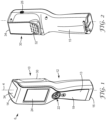
- FIGS. 1-4 and 8 are various views of the device 10 when the door 30 is disposed in a closed position 6.
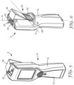
- FIGS. 5-6 and 9 are various views of the device 10 when the door is disposed in an open position 8.
- the actuator portion 32 is adapted to selectively move the door 30 between the closed position 6 and the open position 8.
- the cover portion 34 of door 30 is adapted to close the port 20 when the door is in the closed position 6 and open the port when the door is in the open position 8. When in the open position 8, the cover portion 34 can allow external access to the port 20.
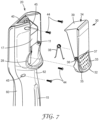
- the door 30 is attached to the housing 12 by a hinge 36 as shown in FIG. 7 .
- the hinge 36 can be any suitable hinge.
- the hinge 36 includes a protuberance 37 that is adapted to be disposed within an opening 11 formed in the housing 12.
- the door 30 can include any suitable number of protuberances 37 such that the hinge 36 attaches the door to the housing 12.
- the hinge 36 can be attached to the housing 12 by inserting the protuberance 37 into the opening 11 disposed in one or both of two sections 60, 62 of the housing 12.
- the sections 60, 62 of the housing 12 can be secured together by screws 44 that are inserted through openings 45.
- the hinge 36 can be disposed in any suitable location on or in the housing 12 and in any suitable orientation relative to the housing axis 4.
- a spring 38 can be disposed between the door 30 and the housing 12. Any suitable spring can be utilized.
- the spring 38 is adapted to allow the door 30 to pivot between the closed position 6 and the open position 8.
- the door 30 is biased in the closed position 6 .
- the spring 38 biases the door 30 in the closed position 6 such that the port 20 is closed to the external environment.
- the cover portion 34 can protect the port 20 and prevent ambient light or other environmental elements (e.g., moisture) from entering the interior of the housing 12 through the port.
- the cover portion 34 can also prevent ambient light from entering a detector disposed within the housing.
- the actuator portion 32 of the door 30 is adapted to rotate the door about a rotation axis 5 as shown in FIG. 6 .
- the rotation axis 5 can be oriented in any suitable relationship to the housing axis 4.
- the rotation axis 5 can be substantially orthogonal to the housing axis 4 as shown in FIG. 6 .
- the phrase "substantially orthogonal” means that the rotation axis 5 is disposed such that an angle of between 85° to 95° is formed with the housing axis 4.
- the rotation axis 5 can be aligned with the hinge 36 ( FIG. 7 ).
- the actuator portion 32 of door 30 is adapted to selectively move the door from the closed position 6 to the open position 8.
- the actuator portion 32 can take any suitable shape or combination of shapes.
- the actuator portion 32 can take a curved shape such that it is adapted to receive a finger of a hand of a user.
- the actuator portion 32 can include a textured surface 33 such that the user can more easily engage the actuator portion to place the door either in the closed position 6 or the open position 8.
- the actuator portion 32 is disposed adjacent the handle portion 18 of the housing 12.
- the phrase "adjacent the handle portion” means that the actuator portion 32 is disposed closer to the handle portion 18 than to either the top surface 14 or the bottom surface 16 of the housing 12.
- the actuator portion 32 is disposed adjacent the handle portion 18 such that the user can grasp the handle portion and engage the actuator portion with a single hand.
- the light detection device 10 can be adapted to allow a user to grasp the handle portion 18 with a hand and, with the same hand, engage the actuator portion 32 to selectively move the door 30 between the closed position 6 and the open position 8.
- the cover portion 34 is adapted to close the port 20 when the door 30 is in the closed position 6 and open the port when the door is in the open position 8 to allow external access to the port. In one or more embodiments, the cover portion 34 of the door 30 is adapted to minimize the amount of ambient light entering the port 20 when the door is in the closed position 6. In one or more embodiments, the door 30 is adapted to prevent substantially all ambient light from entering the port 20 when the door is in the closed position 6. In one or more embodiments, the door 30 is adapted to block a sufficient amount of ambient light from entering the housing 12 such that the ability to detect and measure a light signal associated with the sample is not compromised.
- the cover portion 34 can be disposed in any suitable relationship relative to the housing 12. In one or more embodiments, the cover portion 34 is disposed such that it forms a portion of the top surface 14 of the housing 12. In one or more embodiments, the cover portion 34 can be level or flush with the top surface 14 of the housing 12 when the door 30 is in the closed position 6.
- the port 20 can include a ledge 40 that is adapted to engage the cover portion 34 when the door 30 is in the closed position 6.
- the ledge 40 can take any suitable shape or combination of shapes. Further, the ledge 40 can be disposed along an entire perimeter of the port 20 or along any suitable portion of the perimeter of the port. The combination of the cover portion 34 and ledge 40 can prevent ambient light from entering the port 20 when the door 30 is in the closed position 6.
- the port 20 can also include a gasket (not shown) that is disposed between the cover portion 34 and the ledge 40.
- the gasket can extend along any suitable portion of the ledge 40 of the port 20. In one or more embodiments, the gasket extends along the entire ledge 40.
- the gasket, ledge 40, and the cover portion 34 can combine to prevent ambient light from entering the port 20.
- the gasket can also provide a seal between the cover portion 34 and the ledge 40 to prevent external environmental elements from entering the port 20, e.g., moisture.
- one or more of the gasket, ledge 40, and cover portion 34 can prevent a sample disposed within the housing 12 from undesirably leaking out of the housing.
- the port 20 can also include an overhang (not shown) that covers any space between the top surface 14 and the cover portion 32 when the door 30 is in the closed position 6.
- the overhang can take any suitable shape and be located in any suitable location.
- the overhang can be connected to the top surface 14 and/or the cover portion 34.
- the door 30 can also include a first end 35 and a second end 39 ( FIG. 7 ).
- the actuator portion 32 is adjacent the first end 35 and the cover portion 34 is adjacent the second end 39.
- the phrase "adjacent the first end” means that the actuator portion 32 is disposed closer to the first end 35 of the door 30 than to the second end 39 of the door.
- the phrase "adjacent the second end” means that the cover portion 34 is disposed closer to the second end 39 of the door than to the first end 35.
- the rotation axis 5 can be disposed at any suitable location relative to the door 30. In one or more embodiments, the rotation axis 5 can be disposed between the first end 35 and the second end 39 of the door 30. In one or more embodiments, the rotation axis 5 is disposed at approximately a midpoint between the first end 35 and the second end 39 of the door 30. As used herein, the term “approximately” means that the rotation axis 5 is disposed within 1 cm of the midpoint between the first end 35 and the second end 39 of the door 30. In one or more embodiments, the rotation axis 5 is disposed closer to the first end 35 of the door 30 than to the second end 39. Further, in one or more embodiments, the rotation axis 5 is disposed closer to the second end 39 of the door 30 than to the first end 35.
- the rotation axis 5 is disposed closer to the midpoint between the first and second ends 35, 39 of the door 30 than to either the first end or the second end of the door. In one or more embodiments, the rotation axis 5 is disposed about halfway between the midpoint located between the first and second ends 35, 39 of the door 30 and the first end. In one or more embodiments, the rotation axis 5 is disposed about halfway between the midpoint located between the first and second ends 35, 39 of the door 30 and the second end.
- the actuator portion 32 can be defined as a portion of the door 30 disposed between the rotation axis 5 and the first end 35. Further, in one or more embodiments, the cover portion 34 of the door 30 can be defined as a portion of the door disposed between the rotation axis 5 and the second end 39 of the door.
- the actuator portion 32 can include any suitable portion of door 30, e.g., no greater than about 90%, no greater than about 80%, no greater than about 70%, no greater than about 60%, no greater than about 50%, etc. In one or more embodiments, the actuator portion 32 can be at least about 5%, at least about 10%, at least about 20%, at least about 30%, at least about 40%, at least about 50% of the door 30.
- the cover portion 34 of door 30 can include any suitable portion of the door, e.g., no greater than about 90%, no greater than about 80%, no greater than about70%, no greater than about 60%, no greater than about 50%, etc.
- the door portion 34 can be at least about 5%, at least about 10%, at least about 20%, at least about 30%, at least about 40%, at least about 50% of the door 30.
- the light detection device 10 can also include a switch (not shown) that is coupled to the door 30 and adapted to activate circuitry and/or a detector disposed within the housing (not shown) when the door is disposed in the closed position 6. Any suitable switch or combination of switches can be utilized. Further, in one or more embodiments, the switch can deactivate circuitry and/or a detector disposed within the housing 12 when the door 30 is disposed in the open position 8 to prevent ambient light from damaging the detector. The switch can be disposed in any suitable position relative to the door 30. In one or more embodiments, the switch can be positioned between the actuator portion 32 and the housing 12.
- the door 30 is disposed such that the actuator portion 32 is adjacent the back surface 15 of the housing.
- the phrase "adjacent the back surface” means that the actuator portion 32 is disposed closer to the back surface 15 of housing 12 than to the front surface 13.
- the back surface 15 of the housing 12 can include a recessed portion 17 that is adapted to receive the door 30 as illustrated in FIG. 7 .
- the door 30 can sit within the recessed portion 17 of the back surface 15 such that an outer surface of the door is level or flush with the adjacent back surface.
- the door can be disposed on a side surface of the housing 12 between the front surface 13 and the back surface 15. Further, in one or more embodiments, the door 30 can be disposed on the front surface 13 of the housing 12 adjacent the display 24 such that a user can engage the actuator portion 32 of the door with the thumb of the grasping hand. In such embodiments, the door 30 can include an opening or openings such that the user can access the controls 22 and view the display 24 through the door. In one or more embodiments, the door 30 can be disposed on the front surface 13 of the housing 12 on either side of the display 24 such that the user can access the controls 22 and view the display 24.
- the back surface 15 can also include a finger receiving region 28 adjacent the actuator portion 32 of the door 30 ( FIG. 6 ).
- the phrase "adjacent the actuator portion” means that the finger receiving region 28 of the housing 12 is disposed closer to the actuator portion 32 than to the cover portion 34 of door 30.
- the finger receiving region 28 is adapted to receive one or more fingers of a user's hand when the user grips the handle portion 18 of the light detection device 10.
- the finger receiving region 28 is shaped such that a finger of a user can engage the actuator portion 32 of the door 30 and engage the actuator portion to move the cover portion 34 between the closed position 6 and the open position 8.
- the finger receiving region 28 accommodates a finger of a user to allow the finger to hold the actuator portion against the recessed portion 17 of the back surface 15 of the housing 12.
- the finger receiving region 28 takes a shape that is complementary with the shape of the actuator portion 32 when the actuator portion is engaged and the door 30 is in the open position 8 as illustrated in FIG. 6 .
- FIGS. 8-9 illustrate one technique for utilizing the device 10.
- a hand 50 of the user is shown in FIG. 8 grasping the handle portion 18 of the device 10.
- the hand 50 can engage the actuator portion 32 of the door 30 to move the door between the closed position 6 ( FIG. 8 ) and the open position 8 ( FIG. 9 ).
- the cover portion 34 opens the port 20 to allow external access to the port.
- the user can engage the actuator portion 32 of the door 30 by pressing the actuator portion with a finger or thumb 54 of the hand 50 that is grasping the handle portion 18 of the housing 12.
- Engaging the actuator portion 32 can cause the door 30 to rotate about the rotation axis 5 to the open position 8. Since the door 30 is biased in the closed position 6, pressing the actuator portion 32 of the door 30 opens the door, i.e., places the door in the open position 8.
- a sample or a sampling apparatus can be disposed within the housing 12 through the port 20, e.g., into a receptacle disposed within the housing. While the sample is being disposed within the housing 12, the finger or thumb 54 of the hand 50 of the user can maintain a force on the actuator portion 32 of the door 30 to keep the door in the open position 8.
- a latch (not shown) can be attached to the housing 12.
- the latch can be adapted to hold the door 30 in the open position 8 such that the user's finger can be disengaged from the actuator portion without the door returning to the closed position 6.
- Any suitable latch can be utilized.
- the door 30 can be moved from the open position 8 to the closed position 6 by engaging the actuator portion 32 of the door by applying a force to the actuator portion in a direction toward the interior of the housing 12, thereby releasing the door from the latch. Once the latch is released, the biasing of the door 30 will return the door to the closed position 6 when the user reduces the force applied to the actuator portion 32. In other words, the user can then move the door 30 from the open position 8 to the closed position 6 by releasing the actuator portion 32 such that the biasing of the door returns the door to the closed position 6 and the cover portion 34 of the door closes the port 20 of the housing 12.
- the device 10 can include a switch that activates circuitry disposed within the housing when the sample is disposed within the housing and the door is in the closed position 6.
- the circuitry can be activated by the switch using any suitable technique or combination of techniques.
- One or more characteristics of the sample can be measured after the door 30 has been moved from the open position 8 to the closed position 6. Any suitable characteristic or characteristics of the sample can be measured, e.g., intensity of light emitted by the sample.
- the detection device 10 can also include a tilt detection component (not shown) that can, in one or more embodiments, measure a tilt angle of the detection device 10.
- tilt angle means an angle formed between the housing axis 4 and a vertical axis.
- vertical axis refers to an axis that is aligned with the Earth's gravitational field.
- the tilt detection component can provide feedback to a user when the device 10 is positioned within a proper tilt angle and/or when the device is positioned at an improper tilt angle.
- Such feedback can be provided to the user using any suitable technique or combination of techniques, e.g., the feedback can be provided as a readout on the display 24, or the device 10 can be adapted to provide haptic feedback to the user.
- the user can be warned by an on-screen message on display 24, or the device 10 can provide haptic feedback, when the instrument is not being held at the correct tilt angle and/or when the instrument is being held at the correct tilt angle.
- On-screen instructions can be provided to the user to reorient the device 10 such that it is positioned within the correct tilt angle.
- the tilt detection component can be utilized to indicate to a user any suitable tilt angle or range of tilt angles.
- a desirable tilt angle can be determined, e.g., by the quantity of a sample disposed within the housing, and by the optical properties and configurations of the detector within the housing. In general, the tilt angle can be selected to provide the most accurate detection of one or more characteristics of a sample disposed within the housing.
- the tilt detection component can include any suitable circuitry or elements that can determine an orientation of the device 10 relative to the vertical axis.
- the tilt angle can be measured by a tilt sensor that is sampled by a microprocessor disposed either within the housing 12 of the device 10 or external to the housing 10 and coupled to the tilt sensor either wirelessly or through a wired coupling. Data provided by the tilt sensor can be averaged or normalized to yield a stable approximation of the tilt angle of the device 10 prior to or during analysis of the sample.
- the tilt detection component can be calibrated to have any suitable accuracy. For example, in one or more embodiments, the tilt detection component can be calibrated such that it provides, e.g., a 20% tilt angle measurement accuracy.
- a calibrated 3M Clean-Trace TM NG Luminometer (commercially available from 3M Company, St. Paul, MN) was used to measure light in relative light units (RLUs) emitted by several bioluminescence samples disposed in several different sampling apparatuses.
- the Luminometer was fixtured in a holder for stability and repeatability of tilt angles during the test. The following tilt angles were measured: 0 degrees (vertical), 45 degrees (a commonly observed viewing angle used by users to maximize display contrast), and 90 degrees (simulates the Luminometer resting horizontally on a work surface). These three states were cycled through two times and return to vertical. A plurality of RLU readings was automatically acquired in each angle state to average out temporal variation and assay decay.
- the Luminometer was controlled by a computer running an RLU data logging program with a sample interval of 20 seconds.
- FIG. 18 is a graph of RLUs versus time that illustrates RLUs relative to various tilt angles that were measured. Tilt angles of 45 degrees typically reduced RLU readings by 10%. Tilt angles of 90 degrees typically reduced RLU readings by 25%.
- measuring a sample with an instrument not held at the appropriate angle can yield a measured value difference greater than 20% relative to the real value because the sample being measured can typically be a small volume (less than 1 mL) liquid sample disposed in a cuvette portion of the sampling apparatus, where the sample can have an appreciable meniscus.
- the device is held in an improper angle, at least a portion of the sample can be disposed outside of a light cavity of the detection device of the system that directs light to a detector, thereby reducing a volume of the sample that can emit light into the light cavity and, therefore, potentially yielding an erroneous signal. This tilt can, therefore, affect the radiance of the sample being analyzed.
- the tilt detection component can also be utilized to measure customer usage behaviors and abuse events that can be useful in predicting desired service intervals or provide training and guidance. Further, one or more embodiments of the tilt detection component can provide real-time mathematical normalization of RLU data based on measured tilt angle. This algorithm may be constrained to practical tilt angle limits. For example, measured angles greater than 90 degrees would prompt an immediate warning and suppress a normalization algorithm. In one or more embodiments, providing a user feedback on the tilt angle can allow the user to maintain the same tilt angle across multiple samples, thereby allowing for more consistent readings from sample to sample and from sampling period to sampling period.
- a support member or members can be connected to the housing of the device such that the device can be placed on a working surface at the desired tilt angle.
- FIGS. 10-14 are various views of one embodiment of a light detection device 110. All of the design considerations and possibilities regarding the light detection device 10 of FIGS. 1-9 apply equally to the light detection device 110 of FIGS. 10-14 .
- the light detection device 110 includes a housing 112 that extends along a housing axis 104 between a top surface 114 and a bottom surface 116.
- the housing 112 also includes a front surface 113 that extends between the top surface 114 and the bottom surface 116, and a back surface 115 that also extends between the top surface and the bottom surface.
- device 110 includes a support member 160.
- Support member 160 can be connected to the housing 112 in any suitable location and using any suitable technique or combination of techniques.
- the support member 160 is integral with the housing 112.
- the support member 160 is attached to the housing 112 and can be removed from the housing without damaging either the housing or the support member.
- the support member 160 is connected to the housing 112 adjacent the bottom surface 116.
- the phrase "adjacent the bottom surface” means that the support member 160 is connected to the housing 112 closer to the bottom surface 116 than to the top surface 114.
- the support member 160 can be connected to the housing 112 using any suitable technique or combination of techniques.
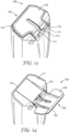
- FIG. 13 is a schematic perspective view of the bottom surface 116 of the housing 112.
- the support member 160 in the illustrated embodiment is attached to the bottom surface 116 via a hinge 170.
- the hinge 170 can include any suitable hinge. In one or more embodiments, the hinge 170 can be a living hinge.
- the hinge 170 can be a ratcheted hinge that includes teeth 171 formed in the bottom surface 116 of the housing 112 that engage one or more notches 173 formed in the hinge.
- the ratcheted hinge 170 can be adapted to allow adjustment of the positioning of the support member 160.
- the support member 160 can be adapted to selectively move from a closed position 106 to an open position 108.
- the support member 160 in a closed position 106, i.e., a second major surface 164 (shown in FIG. 14 ) faces the bottom surface 116 of the housing 112.
- the support member 160 is disposed in the open position 108, i.e., the second major surface 164 of the support member does not face the bottom surface 116 of the housing 112.
- the support member 160 can be fixed in the open position 108 and is not movable to a closed position 106.
- the support member 160 can be adapted to maintain the light detection device 110 in an upright position when the bottom surface 116 and the support member are in contact with a working surface 102 and the support member is in the open position 108 as is shown in FIG. 12 .
- the phrase "upright position" means that the light detection device 10 is disposed such that the top surface 114 is above the bottom surface 116 as viewed from the user's perspective, and the housing axis 104 forms an angle with a vertical axis that is less than 90°. In one or more embodiments, the housing axis 104 forms any suitable angle with the working surface 102 when the light detection device 110 is in the upright position and in contact with the working surface 102.
- angle 101 can be formed between the housing axis 104 and the vertical axis 103. In one or more embodiments, angle 101 can be 0°, at least 0°, no greater than 90°, no greater than 45°, no greater than 30°, no greater than 15°.
- the bottom surface 116 can be adapted such that it is generally perpendicular to the housing axis 104.
- the device 110 can rest on the working surface 102 such that the bottom surface 116 is flat with the working surface and the device is in a vertical position, i.e., the housing axis 104 is parallel to the vertical axis 103.
- the bottom surface 116 can include a recessed portion 117 that is adapted to receive the support member 160 when the member is in the closed position 106 as is illustrated in FIG. 13 .
- the support member 160 is flush with the bottom surface 116 when the member is disposed within the recessed portion 117 and, therefore, in the closed position 106.
- the recessed portion 117 of the bottom surface 116 of the housing 112 is adapted to engage the support member 160 in a snap-fit relationship when the support member is in the closed position 106.
- the support member 160 can be attached to the bottom surface 160 using any suitable hinge such that the support member can be received by a recessed portion formed in both of the front and back surfaces 113, 115.
- the bottom surface 116 can also include a second recessed portion 172 that is adapted to house the hinge 170 such that the support member 160 is flush with the bottom surface 116 when in the closed position 106 ( FIG. 13 ).
- the hinge 170 can be disposed in the second recessed portion 172.
- the second recessed portion 172 can also include a ledge 174 that is adapted to engage the support member 160 when the support member is in the open position 108 ( FIG. 14 ).
- the ledge 174 can prevent the support member 160 from being over rotated such that the first major surface 162 contacts the back surface 115 of the housing 112.
- the user can engage the support member 160 by engaging a portion of the member when the member is in the closed position 106, and moving the member from the closed position to the open position 108 by rotating the member about the hinge 170 until the member engages the ledge 174 of the recessed portion 172.
- the hinge 170 is a ratcheted hinge
- the user can rotate the support member 160 from the closed position 106 to the open position 108 to achieve a selected angle between the first major surface 162 of the support member and the housing axis 104.
- the user can operate the device 110 while either holding the device in a hand or resting the device on the working surface 102 such that the device rests in an upright position at the selected angle 101 between the housing axis 104 and the vertical axis 103.
- the user can, in one or more embodiments, grasp the device 110 and lift it from the working surface 102 to adjust the angle between the first major surface 162 of the support member 160 and the housing axis 104, and then place the device on the working surface at a selected second angle between the housing axis 104 and the vertical axis 103.
- the support member 160 can be held in the closed position 106 using a tab or other interference feature. The support member 160 can then be released from the closed position 106 and moved to the open position 108 either manually or by using a button or switch to move the tab or interference feature out of the way. In one or more embodiments, the support member 160 can move from the closed position 106 to the open position 108 with the assistance of a spring mechanism.
- FIGS. 15-17 are various views of another embodiment of a light detection device 210. All of the design considerations and possibilities regarding the light detection device 10 of FIGS. 1-9 and the light detection device 110 of FIGS. 10-14 apply equally to the light detection device 210 of FIGS. 15-17 .
- the device 210 includes a housing 212 extending along a housing axis 204 between a top surface 214 and a bottom surface 216.
- the device 210 also includes a support member 260 connected to the housing 212 and adapted to be selectively moved between a closed position 206 (as shown in FIGS.
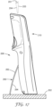
- the support member 260 is also adapted to maintain the light detection device 210 in an upright position when the bottom surface 216 and the support member 260 are in contact with a working surface 202 and the support member is in the open position 208 ( FIG. 17 ).
- the housing axis 204 can form any suitable angle 201 with a vertical axis 203 when the bottom surface 216 and the support member 260 are in contact with the working surface 202 and the support member is in the open position 208.
- the support member 260 is attached to a back surface 215 of the housing 212 and not the bottom surface 216.
- the support member 260 can be in contact with the back surface 215 of the housing when the support member is in the closed position 206 as shown in FIGS. 15-16 .
- a first major surface 262 of the support member 260 can face away from the housing 212 and a second major surface 264 can face the housing.
- the back surface 215 can include a recessed portion (not shown) that is adapted to receive the support member 260 when the support member is in the closed position 206 ( see FIG. 16 ).
- the support member 260 can be snap-fit into the recessed portion such that the support member remains in the closed position 206 as the user holds the device in various orientations.
- the support member 260 can be snap-fit within the recessed portion such that the support member remains in the closed position 206 when the device is in a horizontal orientation, i.e., the housing axis 204 is substantially parallel to a horizontal axis.
- the support member 260 can be flush with the back surface 215 when the support member is in the closed position 206.
- the support member 260 can be connected to the housing 212 using any suitable technique or combination of techniques. In one or more embodiments, the support member 260 can be attached to the housing with any suitable hinge.
- the hinge can also include a ratcheted hinge, e.g., ratcheted hinge 170 of FIGS. 13-14 .
- a user can grasp a portion of the support member 260 and move the support member from the closed position 206 to the open position 208 by rotating the support member about the hinge until a desired angle is formed between the first major surface 262 of the support member and the housing axis 204.
- the user can place the light detection unit 210 on the working surface 202 such that the support member 260 maintains the device in an upright position when the bottom surface 216 of the device and the support member are in contact with the working surface.
- Any suitable angle 201 can be formed between the housing axis 204 and the vertical axis 203.
- the support member 260 can stabilize the light detection device 210 when the device is resting on the working surface 202.
- the support member 260 can be held in the closed position 206 using a tab or other interference feature. The support member 260 can then be released from the closed position 206 to the open position 208 either manually or by using a button or switch to move the tab or interference feature out of the way. In one or more embodiments, the support member 260 can move from the closed position 206 to the open position 208 with the assistance of a spring mechanism.
Landscapes
- Chemical & Material Sciences (AREA)
- Life Sciences & Earth Sciences (AREA)
- Physics & Mathematics (AREA)
- Organic Chemistry (AREA)
- Health & Medical Sciences (AREA)
- Engineering & Computer Science (AREA)
- Proteomics, Peptides & Aminoacids (AREA)
- Zoology (AREA)
- Wood Science & Technology (AREA)
- Analytical Chemistry (AREA)
- General Health & Medical Sciences (AREA)
- Biochemistry (AREA)
- Immunology (AREA)
- General Physics & Mathematics (AREA)
- Microbiology (AREA)
- Genetics & Genomics (AREA)
- Biophysics (AREA)
- Biotechnology (AREA)
- Bioinformatics & Cheminformatics (AREA)
- General Engineering & Computer Science (AREA)
- Molecular Biology (AREA)
- Spectroscopy & Molecular Physics (AREA)
- Pathology (AREA)
- Chemical Kinetics & Catalysis (AREA)
- Plasma & Fusion (AREA)
- Epidemiology (AREA)
- Public Health (AREA)
- Investigating Or Analysing Materials By Optical Means (AREA)
- Investigating, Analyzing Materials By Fluorescence Or Luminescence (AREA)
- Apparatus Associated With Microorganisms And Enzymes (AREA)
Description
- The present invention generally relates to light detection devices.
- Sampling programs are used to monitor critical raw materials, in-process materials, finished goods, and processing environments in the food and beverage industry. Similar sampling programs are also used in healthcare settings to monitor the effectiveness of decontaminating environmental surfaces in a patient environment as well as instruments and devices used in screening and therapeutic procedures. Routine sampling and testing can allow quality assurance personnel to detect undesirable materials, such as microorganisms, at a very early stage and take steps to prevent subsequent contamination of equipment and/or products. A variety of tests can be performed to detect these undesirable materials. Examples of such tests include chemical residue tests (e.g., Adenosine triphosphate (ATP) bioluminescence tests and protein colorimetric tests), culture methods, genetic tests (e.g., PCR), immunodiagnostic tests, and bioluminescent tests.
- Sample-collection devices or apparatuses are typically used to collect surface samples for environmental tests. Commercially-available sample-collection devices include absorbent devices such as sponges, swabs, and the like. In addition, certain sample-collection devices are capable of collecting a predetermined volume of a liquid sample.
- Because of its use as energy "currency" in all metabolizing systems, ATP can indicate the presence of organic or bioorganic residues in a sample. The presence of ATP can be measured using a bioluminescent enzymatic assay. For example, a luciferin/luciferase enzyme assay system uses ATP to generate light. This light output can be detected and quantified in a light detection device, e.g., a luminometer. The presence of ATP in a sample may be a direct indicator of the presence of a microorganism (i.e., the ATP is derived from microorganisms in a sample containing no other sources of ATP), or the ATP may be an indirect indicator of the presence of a microorganism (i.e., the ATP is derived from vegetative or animal matter and indicates that nutrients that support the growth of microorganisms may be present in the sample). In addition, the presence or absence of ATP in a sample is used routinely to assess the efficacy of cleaning processes, e.g., in food, beverage, healthcare (e.g., environmental surfaces, surgical instruments, endoscopes, and other medical devices), water, and sanitation industries.
- For example, ATP measurement systems have been utilized as monitoring tools in the food industry for over 15 years to audit the efficacy of sanitation processes. Such systems can detect very small amounts of ATP (e.g., 1 femtomole) on a variety of surfaces commonly found in food processing operations that need to be cleaned and disinfected. Detecting the presence of ATP on surfaces that are supposed to be sanitized can indicate a failure of the cleaning and disinfection process.
- More recently, ATP monitoring tools have been adopted for a similar purpose in clinical applications to monitor the cleanliness of a patient's environment. There is now compelling clinical evidence that contaminated surfaces in a hospital make an important contribution to the epidemic and endemic transmission, e.g., of C. difficile, VRE, MRSA, A. baumannii, and P. aeruginosa, and to the endemic transmission of norovirus. Effective infection prevention programs include systematic monitoring of the environment's cleanliness. ATP monitoring, for example, can provide a quantitative measurement system that can be used to support such a program.
-
WO 2013/020103 A1 describes meters and methods for sampling, transporting, and/or analyzing a fluid sample. The meters may include a meter housing and a cartridge. In some instances, the meter may include a tower which may engage one or more portions of a cartridge. The meter housing may include an imaging system, which may or may not be included in the tower. The cartridge may include one or more sampling arrangements, which may be configured to collect a fluid sample from a sampling site. A sampling arrangement may include a skin-penetration member, a hub, and a quantification member. - In general, the present disclosure provides a light detection device as set out in
claim 1. The light detection device, which is a luminometer, a photometer, a turbidimeter, a colorimeter or a fluorometer, includes a housing comprising a top surface and a bottom surface, wherein the housing extends along a housing axis between the top surface and the bottom surface, wherein the housing further comprises a handle portion disposed between the top surface and the bottom surface, and a port formed in the top surface of the housing, wherein the port is adapted to receive a sample. The detection device also includes a door connected to the housing. The door includes an actuator portion adapted to selectively move the door between a closed position and an open position; and a cover portion integral with the actuator portion and adapted to close the port when the door is in the closed position and open the port when the door is in the open position to allow external access to the port. The actuator portion is disposed adjacent the handle portion of the housing, such that the actuator portion is disposed closer to the handle portion than to either the top surface or the bottom surface of the housing and so as to allow a user to grasp a handle portion with a hand and, with the same hand, engage the actuator portion to selectively move the door between the closed position and the open position. The light detection device further comprises a hinge, wherein the door is connected to the housing by the hinge and biased in the closed position, wherein the actuator portion is adapted to selectively move the door by rotating the door between the closed position and the open position and wherein the light detection device is configured and arranged such that when the user presses the actuator portion the door rotates from the closed position to the open position and the door returns to the closed position under the biasing of the door upon release of the actuator portion. - All headings provided herein are for the convenience of the reader and should not be used to limit the meaning of any text that follows the heading, unless so specified.
- The words "preferred" and "preferably" refer to embodiments of the disclosure that may afford certain benefits, under certain circumstances; however, other embodiments may also be preferred, under the same or other circumstances. Furthermore, the recitation of one or more preferred embodiments does not imply that other embodiments are not useful, and is not intended to exclude other embodiments from the scope of the disclosure.
- In this application, terms such as "a," "an," and "the" are not intended to refer to only a singular entity but include the general class of which a specific example may be used for illustration. The terms "a," "an," and "the" are used interchangeably with the term "at least one."
- The phrases "at least one of" and "comprises at least one of' followed by a list refers to any one of the items in the list and any combination of two or more items in the list.
- The term "and/or" means one or all of the listed elements or a combination of any two or more of the listed elements.
- As used herein in connection with a measured quantity, the term "about" refers to that variation in the measured quantity as would be expected by the skilled artisan making the measurement and exercising a level of care commensurate with the objective of the measurement and the precision of the measuring equipment used. Herein, "up to" a number (e.g., up to 50) includes the number (e.g., 50).
- Also herein, the recitations of numerical ranges by endpoints include all numbers subsumed within that range as well as the endpoints (e.g., 1 to 5 includes 1, 1.5, 2, 2.75, 3, 3.80, 4, 5, etc.).
- These and other aspects of the present disclosure will be apparent from the detailed description below. In no event, however, should the above summaries be construed as limitations on the claimed subject matter, which subject matter is defined solely by the attached claims.
- Throughout the specification, reference is made to the appended drawings, where like reference numerals designate like elements, and wherein:
-
FIG. 1 is a schematic front perspective view of one embodiment of a light detection device including a door that is disposed in a closed position. -
FIG. 2 is a schematic rear perspective view of the light detection device ofFIG. 1 with the door of the device disposed in the closed position. -
FIG. 3 is a schematic right-side view of the light detection device ofFIG. 1 with the door of the device disposed in the closed position. -
FIG. 4 is a top plan view of the light detection device ofFIG. 1 with the door of the device disposed in the closed position. -
FIG. 5 is a schematic front perspective view of the light detection device ofFIG. 1 when the door of the device is disposed in an open position. -
FIG. 6 is a schematic rear perspective view of the light detection device ofFIG. 1 with the door of the device disposed in the open position. -
FIG. 7 is a schematic exploded view of a portion of the light detection device ofFIG. 1 . -
FIG. 8 is a schematic front view of the light detection device ofFIG. 1 grasped by a hand of a user and the door of the device disposed in the closed position. -
FIG. 9 is a schematic left-side view of the light detection device ofFIG. 1 grasped by the hand of the user and the door of the device disposed in the open position. -
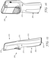
FIG. 10 is a schematic rear perspective view of another embodiment of a light detection device including a support member that is disposed in an open position. -
FIG. 11 is a schematic left-side view of the light detection device ofFIG. 10 with the support member disposed in a closed position. -
FIG. 12 is a schematic left-side view of the light detection device ofFIG. 10 disposed on a working surface and the support member disposed in the open position. -
FIG. 13 is a schematic bottom perspective view of a portion of the light detection device ofFIG. 10 with the support member disposed in the closed position. -
FIG. 14 is a schematic bottom perspective view of a portion of the light detection device ofFIG. 10 with the support member disposed in the open position. -
FIG. 15 is a schematic left-side view of another embodiment of a light detection device including a support member disposed in a closed position. -
FIG. 16 is a schematic rear perspective view of the light detection device ofFIG. 15 with the support member disposed in the closed position. -
FIG. 17 is a schematic left-side view of the light detection device ofFIG. 15 with the support member disposed in an open position. -
FIG. 18 is a graph of relative light units (RLUs) versus time as related to tilt angle for several supply apparatuses disposed at various tilt angles. - In general, the present disclosure provides a light detection device that include a housing comprising a top surface and a bottom surface, wherein the housing extends along a housing axis between the top surface and the bottom surface, wherein the housing further comprises a handle portion disposed between the top surface and the bottom surface, and a port formed in the top surface of the housing wherein the port is adapted to receive a sample. The detection device also includes a door connected to the housing. The door includes an actuator portion and a cover portion integral with the actuator portion. The actuator portion is adapted to selectively move the door between a closed position and an open position. When in the closed position, the cover portion is adapted to close the port. Further, when in the open position, the cover portion is adapted to open the port to allow external access to the port. The actuator portion is disposed adjacent the handle portion of the housing, such that the actuator portion is disposed closer to the handle portion than to either the top surface or the bottom surface of the housing and so as to allow a user to grasp a handle portion of the housing with a hand and, with the same hand, engage the actuator portion to selectively move the door between the closed position and the open position with the hand. The light detection device further comprises a hinge, wherein the door is connected to the housing by the hinge and biased in the closed position and wherein the actuator portion is adapted to selectively move the door by rotating the door between the closed position and the open position. The device is configured and arranged such that when the user presses the actuator portion the door rotates from the closed position to the open position and the door returns to the closed position under the biasing of the door upon release of the actuator portion.
- The light detection devices described herein include luminometers, photometers (UV/visible), turbidimeters, colorimeters, fluorometers (e.g., portable devices that use light detection for environmental surface and water sampling, including both biological (microbial) testing and chemical content testing). In one or more embodiments, a light detection device can include a light source (e.g., one or more light emitting diodes), a sample chamber, a light detector (e.g., a photomultiplier tube (PMT), a photodiode, etc.), and in some embodiments an optical system (including, e.g., one or more reflectors, filters, or lenses) to direct the light. In one or more embodiments, a test sample can emit light that is detected by a detector of the light detection device. Devices that detect light from a sample or detect the interaction of light with a sample can include one or more elements that block ambient light from interacting with the detector of the device, e.g., doors, gaskets, opaque housings, etc.
- The light detection device can be utilized in any suitable application. For example, in one or more embodiments, the light detection device can be utilized to detect and measure light emitted by a sample disposed within the device. The sample can include any suitable sample, e.g., a bioluminescent sample. In one or more embodiments, the light detection device can detect the presence of ATP in a bioluminescent sample by analyzing light emitted by the sample that is produced by a luciferin-luciferase enzymatic reaction.
- The accuracy and repeatability of currently available ATP detection systems can vary significantly. Such variability can be caused by difficulties in acquiring samples in a repeatable manner. Further, systems that employ a luciferin-luciferase detection chemistry can vary because of the lack of repeatability of how the reagent composition is formulated and the form factor employed to provide the reagents in an assay. In addition, the optical characteristics of the detection system can affect accuracy and repeatability. For example, some detection systems utilize a photomultiplier tube as the detector whereas other systems employ photodiodes. These detection systems can include a port that is connected to a detector disposed within a housing of the system. A sample can be disposed within the housing through the port. These ports, however, can allow ambient light to be transmitted into the detector, which can hinder accurate readings and potentially damage the detector. Some systems may include a door or cap that covers the port to prevent ambient light from being transmitted into the detector. These systems, however, may be awkward to operate as they may require one hand to grasp the system and the other to open and close the door that covers the port.
-
FIGS. 1-9 are various views of one embodiment of alight detection device 10. Thelight detection device 10 may be e.g., a luminometer. In one or more embodiments, thedevice 10 can be part of a light detection system that can also include a sampling apparatus (not shown) that can be disposed within thedevice 10 and contain a sample. Any suitable sampling apparatus can be utilized, e.g., the sampling apparatuses described inPCT Patent Publication No. WO 2014/007846 A1 andU.S. Patent Publication No. 2012/0329081 A1 . - The
device 10 includes ahousing 12. Thehousing 12 can take an ergonomic shape or combination of shapes that allows a user to grasp the housing and operate thedevice 10 with a single hand. Further, thehousing 12 can be a single, unitary housing or can include two or more pieces, sections, or portions that are attached together using any suitable technique or combination of techniques. Thehousing 12 extends along ahousing axis 4 between atop surface 14 and abottom surface 16. Thehousing 12 also includes anhandle portion 18 disposed between thetop surface 14 and thebottom surface 16. Thehandle portion 18 can include any suitable shape or combination of shapes. Thehousing 12 can also include afront surface 13 that extends between thetop surface 14 and thebottom surface 16, and aback surface 15 that also extends between the top surface and the bottom surface. - The
housing 12 also includes aport 20 disposed in thetop surface 14 of the housing (FIGS. 5-7 and9 ). Theport 20 can be adapted to allow a user to dispose a sample within thehousing 12 such that light emitted by or interacting with the sample can be detected by a detector (not shown) disposed within the housing. The detector can be any suitable detector, e.g., the detectors described in cofiledU.S. Provisional Patent Application No. 62/132,774, filed March 13, 2015 port 20 can be connected to the detector such that a sample can be disposed within the housing through the port and positioned within the housing such that the detector can measure one or more characteristics of the sample. For example, if the sample includes a photoluminescent sample, then the detector can be utilized to measure, e.g., an intensity of light emitted by the photoluminescent sample. - The
port 20 is adapted to receive a sample. The sample can be disposed within thehousing 20 in any suitable manner. For example, in one or more embodiments, the sample can be directly disposed within the housing through theport 20. In one or more embodiments, the sample can be contained within a sampling apparatus that is adapted to be disposed within the housing by being inserted into theport 20. Theport 20 can take any suitable shape or combination of shapes. In one or more embodiments, theport 20 can be adapted to receive a sampling apparatus. - In one or more embodiments, the
port 20 can be connected to a receptacle (not shown) that is disposed within thehousing 12. The receptacle can be adapted to receive a sampling apparatus and position the apparatus within the housing such that the detector can measure one or more characteristics of a sample disposed within the sampling apparatus. Any suitable receptacle can be utilized, e.g., one or more of the receptacles described in cofiledU.S. Provisional Patent Application No. 62/132,774, filed March 13, 2015 - The
light detection device 10 can also include one ormore controls 22 that are adapted to provide an interface for the user to perform various functions with thedevice 12. Any suitable control or controls 22 can be provided with thedevice 10. Further, in one or more embodiments, thecontrols 22 can be disposed in any suitable location on or in thehousing 12. For example, in the embodiment illustrated inFIG. 1 , thecontrols 22 are disposed on or in afront surface 13 of thehousing 12 such that a user can grasp thehandle portion 18 of thehousing 12 and operate the controls with a thumb or finger of the grasping hand. Such positioning of thecontrols 22 can allow operation of thedevice 10 with a single hand. Thecontrols 22 can provide an interface for a user and can be electrically coupled to any suitable circuitry disposed within thehousing 12 of thedevice 10. Such circuitry can include any suitable electronic device or devices, e.g., one or more controllers, processors, storage devices, power converters, analog/digital converters, GPS components, wireless antennas and receivers, etc. The circuitry can be electrically coupled to any suitable power source or sources, e.g., batteries, external power sources, etc. The circuitry can be connected to any suitable external device or power source through, e.g., one or moreadditional ports 26 disposed on or in the housing in any suitable location. - The
device 10 can also include adisplay 24 that is adapted to provide a user with an interface with the circuitry disposed within thehousing 12 of the device. Thedisplay 24 can be in any suitable location on or in thehousing 12. In the embodiment illustrated inFIG. 1 , thedisplay 24 is disposed in thefront surface 13 of the housing. Thedisplay 24 can include any suitable display. In one or more embodiments, thedisplay 24 can be a touch-sensitive display that can provide the user with control of the device and can also display information to the user. Any suitable touchsensitive display 24 can be utilized withdevice 10. - The
light detection device 10 also includes adoor 30. Thedoor 30 is connected to thehousing 12 of thedevice 10 using any suitable technique or combination of techniques. Thedoor 30 can include any suitable material or combination of materials. In one or more embodiments, thedoor 30 includes the same material or combination of materials as thehousing 12 of thedevice 10. Further, thedoor 30 can take any suitable shape or combination of shapes and have any suitable dimensions. - The
door 30 includes anactuator portion 32 and acover portion 34. Theactuator portion 32 is integral with thecover portion 34 - The
door 30 is adapted such that it can be disposed in a closed position or an open position. For example,FIGS. 1-4 and8 are various views of thedevice 10 when thedoor 30 is disposed in a closed position 6. Further, for example,FIGS. 5-6 and9 are various views of thedevice 10 when the door is disposed in an open position 8. Theactuator portion 32 is adapted to selectively move thedoor 30 between the closed position 6 and the open position 8. Further, thecover portion 34 ofdoor 30 is adapted to close theport 20 when the door is in the closed position 6 and open the port when the door is in the open position 8. When in the open position 8, thecover portion 34 can allow external access to theport 20. - The
door 30 is attached to thehousing 12 by ahinge 36 as shown inFIG. 7 . Thehinge 36 can be any suitable hinge. In the embodiment illustrated inFIG. 7 , thehinge 36 includes aprotuberance 37 that is adapted to be disposed within anopening 11 formed in thehousing 12. Thedoor 30 can include any suitable number ofprotuberances 37 such that thehinge 36 attaches the door to thehousing 12. In one or more embodiments, thehinge 36 can be attached to thehousing 12 by inserting theprotuberance 37 into theopening 11 disposed in one or both of twosections housing 12. Thesections housing 12 can be secured together byscrews 44 that are inserted throughopenings 45. Thehinge 36 can be disposed in any suitable location on or in thehousing 12 and in any suitable orientation relative to thehousing axis 4. - Further, in one or more embodiments, a
spring 38 can be disposed between thedoor 30 and thehousing 12. Any suitable spring can be utilized. Thespring 38 is adapted to allow thedoor 30 to pivot between the closed position 6 and the open position 8. Thedoor 30 is biased in the closed position 6 . In the embodiment illustrated inFIG. 7 , thespring 38 biases thedoor 30 in the closed position 6 such that theport 20 is closed to the external environment. By biasing thedoor 30 in the closed position 6, thecover portion 34 can protect theport 20 and prevent ambient light or other environmental elements (e.g., moisture) from entering the interior of thehousing 12 through the port. When in the closed position 6, thecover portion 34 can also prevent ambient light from entering a detector disposed within the housing. - The
actuator portion 32 of thedoor 30 is adapted to rotate the door about a rotation axis 5 as shown inFIG. 6 . The rotation axis 5 can be oriented in any suitable relationship to thehousing axis 4. For example, in one or more embodiments, the rotation axis 5 can be substantially orthogonal to thehousing axis 4 as shown inFIG. 6 . As used herein, the phrase "substantially orthogonal" means that the rotation axis 5 is disposed such that an angle of between 85° to 95° is formed with thehousing axis 4. In one or more embodiments, the rotation axis 5 can be aligned with the hinge 36 (FIG. 7 ). - The
actuator portion 32 ofdoor 30 is adapted to selectively move the door from the closed position 6 to the open position 8. Further, theactuator portion 32 can take any suitable shape or combination of shapes. In one or more embodiments, theactuator portion 32 can take a curved shape such that it is adapted to receive a finger of a hand of a user. Further, in one or more embodiments, theactuator portion 32 can include atextured surface 33 such that the user can more easily engage the actuator portion to place the door either in the closed position 6 or the open position 8. - The
actuator portion 32 is disposed adjacent thehandle portion 18 of thehousing 12. As used herein, the phrase "adjacent the handle portion" means that theactuator portion 32 is disposed closer to thehandle portion 18 than to either thetop surface 14 or thebottom surface 16 of thehousing 12. Theactuator portion 32 is disposed adjacent thehandle portion 18 such that the user can grasp the handle portion and engage the actuator portion with a single hand. In other words, thelight detection device 10 can be adapted to allow a user to grasp thehandle portion 18 with a hand and, with the same hand, engage theactuator portion 32 to selectively move thedoor 30 between the closed position 6 and the open position 8. - The
cover portion 34 is adapted to close theport 20 when thedoor 30 is in the closed position 6 and open the port when the door is in the open position 8 to allow external access to the port. In one or more embodiments, thecover portion 34 of thedoor 30 is adapted to minimize the amount of ambient light entering theport 20 when the door is in the closed position 6. In one or more embodiments, thedoor 30 is adapted to prevent substantially all ambient light from entering theport 20 when the door is in the closed position 6. In one or more embodiments, thedoor 30 is adapted to block a sufficient amount of ambient light from entering thehousing 12 such that the ability to detect and measure a light signal associated with the sample is not compromised. - The
cover portion 34 can be disposed in any suitable relationship relative to thehousing 12. In one or more embodiments, thecover portion 34 is disposed such that it forms a portion of thetop surface 14 of thehousing 12. In one or more embodiments, thecover portion 34 can be level or flush with thetop surface 14 of thehousing 12 when thedoor 30 is in the closed position 6. - In one or more embodiments, the
port 20 can include aledge 40 that is adapted to engage thecover portion 34 when thedoor 30 is in the closed position 6. Theledge 40 can take any suitable shape or combination of shapes. Further, theledge 40 can be disposed along an entire perimeter of theport 20 or along any suitable portion of the perimeter of the port. The combination of thecover portion 34 andledge 40 can prevent ambient light from entering theport 20 when thedoor 30 is in the closed position 6. - In one or more embodiments, the
port 20 can also include a gasket (not shown) that is disposed between thecover portion 34 and theledge 40. The gasket can extend along any suitable portion of theledge 40 of theport 20. In one or more embodiments, the gasket extends along theentire ledge 40. The gasket,ledge 40, and thecover portion 34 can combine to prevent ambient light from entering theport 20. Further, in one or more embodiments, the gasket can also provide a seal between thecover portion 34 and theledge 40 to prevent external environmental elements from entering theport 20, e.g., moisture. Further, one or more of the gasket,ledge 40, and coverportion 34 can prevent a sample disposed within thehousing 12 from undesirably leaking out of the housing. - In one or more embodiments, the
port 20 can also include an overhang (not shown) that covers any space between thetop surface 14 and thecover portion 32 when thedoor 30 is in the closed position 6. The overhang can take any suitable shape and be located in any suitable location. In one or more embodiments, the overhang can be connected to thetop surface 14 and/or thecover portion 34. - The
door 30 can also include afirst end 35 and a second end 39 (FIG. 7 ). In one or more embodiments, theactuator portion 32 is adjacent thefirst end 35 and thecover portion 34 is adjacent thesecond end 39. As used herein, the phrase "adjacent the first end" means that theactuator portion 32 is disposed closer to thefirst end 35 of thedoor 30 than to thesecond end 39 of the door. Similarly, the phrase "adjacent the second end" means that thecover portion 34 is disposed closer to thesecond end 39 of the door than to thefirst end 35. - As mentioned herein, the rotation axis 5 can be disposed at any suitable location relative to the
door 30. In one or more embodiments, the rotation axis 5 can be disposed between thefirst end 35 and thesecond end 39 of thedoor 30. In one or more embodiments, the rotation axis 5 is disposed at approximately a midpoint between thefirst end 35 and thesecond end 39 of thedoor 30. As used herein, the term "approximately" means that the rotation axis 5 is disposed within 1 cm of the midpoint between thefirst end 35 and thesecond end 39 of thedoor 30. In one or more embodiments, the rotation axis 5 is disposed closer to thefirst end 35 of thedoor 30 than to thesecond end 39. Further, in one or more embodiments, the rotation axis 5 is disposed closer to thesecond end 39 of thedoor 30 than to thefirst end 35. - In one or more embodiments, the rotation axis 5 is disposed closer to the midpoint between the first and second ends 35, 39 of the
door 30 than to either the first end or the second end of the door. In one or more embodiments, the rotation axis 5 is disposed about halfway between the midpoint located between the first and second ends 35, 39 of thedoor 30 and the first end. In one or more embodiments, the rotation axis 5 is disposed about halfway between the midpoint located between the first and second ends 35, 39 of thedoor 30 and the second end. - In one or more embodiments, the
actuator portion 32 can be defined as a portion of thedoor 30 disposed between the rotation axis 5 and thefirst end 35. Further, in one or more embodiments, thecover portion 34 of thedoor 30 can be defined as a portion of the door disposed between the rotation axis 5 and thesecond end 39 of the door. Theactuator portion 32 can include any suitable portion ofdoor 30, e.g., no greater than about 90%, no greater than about 80%, no greater than about 70%, no greater than about 60%, no greater than about 50%, etc. In one or more embodiments, theactuator portion 32 can be at least about 5%, at least about 10%, at least about 20%, at least about 30%, at least about 40%, at least about 50% of thedoor 30. Further, thecover portion 34 ofdoor 30 can include any suitable portion of the door, e.g., no greater than about 90%, no greater than about 80%, no greater than about70%, no greater than about 60%, no greater than about 50%, etc. In one or more embodiments, thedoor portion 34 can be at least about 5%, at least about 10%, at least about 20%, at least about 30%, at least about 40%, at least about 50% of thedoor 30. - The
light detection device 10 can also include a switch (not shown) that is coupled to thedoor 30 and adapted to activate circuitry and/or a detector disposed within the housing (not shown) when the door is disposed in the closed position 6. Any suitable switch or combination of switches can be utilized. Further, in one or more embodiments, the switch can deactivate circuitry and/or a detector disposed within thehousing 12 when thedoor 30 is disposed in the open position 8 to prevent ambient light from damaging the detector. The switch can be disposed in any suitable position relative to thedoor 30. In one or more embodiments, the switch can be positioned between theactuator portion 32 and thehousing 12. - In one or more embodiments, the
door 30 is disposed such that theactuator portion 32 is adjacent theback surface 15 of the housing. As used herein, the phrase "adjacent the back surface" means that theactuator portion 32 is disposed closer to theback surface 15 ofhousing 12 than to thefront surface 13. In one or more embodiments, theback surface 15 of thehousing 12 can include a recessedportion 17 that is adapted to receive thedoor 30 as illustrated inFIG. 7 . In one or more embodiments, thedoor 30 can sit within the recessedportion 17 of theback surface 15 such that an outer surface of the door is level or flush with the adjacent back surface. - In one or more embodiments, the door can be disposed on a side surface of the
housing 12 between thefront surface 13 and theback surface 15. Further, in one or more embodiments, thedoor 30 can be disposed on thefront surface 13 of thehousing 12 adjacent thedisplay 24 such that a user can engage theactuator portion 32 of the door with the thumb of the grasping hand. In such embodiments, thedoor 30 can include an opening or openings such that the user can access thecontrols 22 and view thedisplay 24 through the door. In one or more embodiments, thedoor 30 can be disposed on thefront surface 13 of thehousing 12 on either side of thedisplay 24 such that the user can access thecontrols 22 and view thedisplay 24. - The
back surface 15 can also include afinger receiving region 28 adjacent theactuator portion 32 of the door 30 (FIG. 6 ). As used herein, the phrase "adjacent the actuator portion" means that thefinger receiving region 28 of thehousing 12 is disposed closer to theactuator portion 32 than to thecover portion 34 ofdoor 30. Thefinger receiving region 28 is adapted to receive one or more fingers of a user's hand when the user grips thehandle portion 18 of thelight detection device 10. Thefinger receiving region 28 is shaped such that a finger of a user can engage theactuator portion 32 of thedoor 30 and engage the actuator portion to move thecover portion 34 between the closed position 6 and the open position 8. In one or more embodiments, when theactuator portion 32 is engaged such that thedoor 30 is moved to the open position 8, thefinger receiving region 28 accommodates a finger of a user to allow the finger to hold the actuator portion against the recessedportion 17 of theback surface 15 of thehousing 12. In one or more embodiments, thefinger receiving region 28 takes a shape that is complementary with the shape of theactuator portion 32 when the actuator portion is engaged and thedoor 30 is in the open position 8 as illustrated inFIG. 6 . - The
light detection device 10 can be utilized in any suitable manner to measure one or more characteristics of a sample disposed within thehousing 12 of the device. For example,FIGS. 8-9 illustrate one technique for utilizing thedevice 10. As illustrated, ahand 50 of the user is shown inFIG. 8 grasping thehandle portion 18 of thedevice 10. Thehand 50 can engage theactuator portion 32 of thedoor 30 to move the door between the closed position 6 (FIG. 8 ) and the open position 8 (FIG. 9 ). When in the open position 8, thecover portion 34 opens theport 20 to allow external access to the port. In one or more embodiments, the user can engage theactuator portion 32 of thedoor 30 by pressing the actuator portion with a finger orthumb 54 of thehand 50 that is grasping thehandle portion 18 of thehousing 12. Engaging theactuator portion 32 can cause thedoor 30 to rotate about the rotation axis 5 to the open position 8. Since thedoor 30 is biased in the closed position 6, pressing theactuator portion 32 of thedoor 30 opens the door, i.e., places the door in the open position 8. - When the
door 30 is in the open position 8 as shown inFIG. 9 , a sample or a sampling apparatus can be disposed within thehousing 12 through theport 20, e.g., into a receptacle disposed within the housing. While the sample is being disposed within thehousing 12, the finger orthumb 54 of thehand 50 of the user can maintain a force on theactuator portion 32 of thedoor 30 to keep the door in the open position 8. - In one or more embodiments, a latch (not shown) can be attached to the
housing 12. The latch can be adapted to hold thedoor 30 in the open position 8 such that the user's finger can be disengaged from the actuator portion without the door returning to the closed position 6. Any suitable latch can be utilized. In embodiments where a latch is included, thedoor 30 can be moved from the open position 8 to the closed position 6 by engaging theactuator portion 32 of the door by applying a force to the actuator portion in a direction toward the interior of thehousing 12, thereby releasing the door from the latch. Once the latch is released, the biasing of thedoor 30 will return the door to the closed position 6 when the user reduces the force applied to theactuator portion 32. In other words, the user can then move thedoor 30 from the open position 8 to the closed position 6 by releasing theactuator portion 32 such that the biasing of the door returns the door to the closed position 6 and thecover portion 34 of the door closes theport 20 of thehousing 12. - In one or more embodiments, the
device 10 can include a switch that activates circuitry disposed within the housing when the sample is disposed within the housing and the door is in the closed position 6. The circuitry can be activated by the switch using any suitable technique or combination of techniques. One or more characteristics of the sample can be measured after thedoor 30 has been moved from the open position 8 to the closed position 6. Any suitable characteristic or characteristics of the sample can be measured, e.g., intensity of light emitted by the sample. - In one or more embodiments, the
detection device 10 can also include a tilt detection component (not shown) that can, in one or more embodiments, measure a tilt angle of thedetection device 10. As used herein, the term "tilt angle" means an angle formed between thehousing axis 4 and a vertical axis. As used herein, the term "vertical axis" refers to an axis that is aligned with the Earth's gravitational field. The tilt detection component can provide feedback to a user when thedevice 10 is positioned within a proper tilt angle and/or when the device is positioned at an improper tilt angle. Such feedback can be provided to the user using any suitable technique or combination of techniques, e.g., the feedback can be provided as a readout on thedisplay 24, or thedevice 10 can be adapted to provide haptic feedback to the user. For example, during detection of light emitted by a sample, the user can be warned by an on-screen message ondisplay 24, or thedevice 10 can provide haptic feedback, when the instrument is not being held at the correct tilt angle and/or when the instrument is being held at the correct tilt angle. On-screen instructions can be provided to the user to reorient thedevice 10 such that it is positioned within the correct tilt angle. The tilt detection component can be utilized to indicate to a user any suitable tilt angle or range of tilt angles. In one or more embodiments, a desirable tilt angle can be determined, e.g., by the quantity of a sample disposed within the housing, and by the optical properties and configurations of the detector within the housing. In general, the tilt angle can be selected to provide the most accurate detection of one or more characteristics of a sample disposed within the housing. - The tilt detection component can include any suitable circuitry or elements that can determine an orientation of the
device 10 relative to the vertical axis. For example, in one or more embodiments, the tilt angle can be measured by a tilt sensor that is sampled by a microprocessor disposed either within thehousing 12 of thedevice 10 or external to thehousing 10 and coupled to the tilt sensor either wirelessly or through a wired coupling. Data provided by the tilt sensor can be averaged or normalized to yield a stable approximation of the tilt angle of thedevice 10 prior to or during analysis of the sample. The tilt detection component can be calibrated to have any suitable accuracy. For example, in one or more embodiments, the tilt detection component can be calibrated such that it provides, e.g., a 20% tilt angle measurement accuracy. - A calibrated 3M Clean-Trace™ NG Luminometer (commercially available from 3M Company, St. Paul, MN) was used to measure light in relative light units (RLUs) emitted by several bioluminescence samples disposed in several different sampling apparatuses. The Luminometer was fixtured in a holder for stability and repeatability of tilt angles during the test. The following tilt angles were measured: 0 degrees (vertical), 45 degrees (a commonly observed viewing angle used by users to maximize display contrast), and 90 degrees (simulates the Luminometer resting horizontally on a work surface). These three states were cycled through two times and return to vertical. A plurality of RLU readings was automatically acquired in each angle state to average out temporal variation and assay decay. The Luminometer was controlled by a computer running an RLU data logging program with a sample interval of 20 seconds.
-
FIG. 18 is a graph of RLUs versus time that illustrates RLUs relative to various tilt angles that were measured. Tilt angles of 45 degrees typically reduced RLU readings by 10%. Tilt angles of 90 degrees typically reduced RLU readings by 25%. - While not wishing to be bound by any particular theory, measuring a sample with an instrument not held at the appropriate angle can yield a measured value difference greater than 20% relative to the real value because the sample being measured can typically be a small volume (less than 1 mL) liquid sample disposed in a cuvette portion of the sampling apparatus, where the sample can have an appreciable meniscus. When the device is held in an improper angle, at least a portion of the sample can be disposed outside of a light cavity of the detection device of the system that directs light to a detector, thereby reducing a volume of the sample that can emit light into the light cavity and, therefore, potentially yielding an erroneous signal. This tilt can, therefore, affect the radiance of the sample being analyzed.
- In one or more embodiments, the tilt detection component can also be utilized to measure customer usage behaviors and abuse events that can be useful in predicting desired service intervals or provide training and guidance. Further, one or more embodiments of the tilt detection component can provide real-time mathematical normalization of RLU data based on measured tilt angle. This algorithm may be constrained to practical tilt angle limits. For example, measured angles greater than 90 degrees would prompt an immediate warning and suppress a normalization algorithm. In one or more embodiments, providing a user feedback on the tilt angle can allow the user to maintain the same tilt angle across multiple samples, thereby allowing for more consistent readings from sample to sample and from sampling period to sampling period.
- Any suitable technique or combination of techniques can be utilized to maintain the
light detection device 10 in a position having a desired tilt angle. For example, in one or more embodiments, a support member or members can be connected to the housing of the device such that the device can be placed on a working surface at the desired tilt angle. - For example,
FIGS. 10-14 are various views of one embodiment of alight detection device 110. All of the design considerations and possibilities regarding thelight detection device 10 ofFIGS. 1-9 apply equally to thelight detection device 110 ofFIGS. 10-14 . Thelight detection device 110 includes ahousing 112 that extends along ahousing axis 104 between atop surface 114 and abottom surface 116. Thehousing 112 also includes afront surface 113 that extends between thetop surface 114 and thebottom surface 116, and aback surface 115 that also extends between the top surface and the bottom surface. - One difference between
light detection device 110 anddevice 10 ofFIGS. 1-9 is thatdevice 110 includes asupport member 160.Support member 160 can be connected to thehousing 112 in any suitable location and using any suitable technique or combination of techniques. In one or more embodiments, thesupport member 160 is integral with thehousing 112. In one or more embodiments, thesupport member 160 is attached to thehousing 112 and can be removed from the housing without damaging either the housing or the support member. - In the embodiment illustrated in
FIGS. 10-14 , thesupport member 160 is connected to thehousing 112 adjacent thebottom surface 116. As used herein, the phrase "adjacent the bottom surface" means that thesupport member 160 is connected to thehousing 112 closer to thebottom surface 116 than to thetop surface 114. Thesupport member 160 can be connected to thehousing 112 using any suitable technique or combination of techniques. For example,FIG. 13 is a schematic perspective view of thebottom surface 116 of thehousing 112. Thesupport member 160 in the illustrated embodiment is attached to thebottom surface 116 via ahinge 170. Thehinge 170 can include any suitable hinge. In one or more embodiments, thehinge 170 can be a living hinge. Further, in one or more embodiments, thehinge 170 can be a ratcheted hinge that includesteeth 171 formed in thebottom surface 116 of thehousing 112 that engage one or more notches 173 formed in the hinge. The ratchetedhinge 170 can be adapted to allow adjustment of the positioning of thesupport member 160. - In one or more embodiments, the
support member 160 can be adapted to selectively move from aclosed position 106 to anopen position 108. For example, inFIG. 13 , thesupport member 160 is in aclosed position 106, i.e., a second major surface 164 (shown inFIG. 14 ) faces thebottom surface 116 of thehousing 112. InFIG. 14 , thesupport member 160 is disposed in theopen position 108, i.e., the secondmajor surface 164 of the support member does not face thebottom surface 116 of thehousing 112. In one or more embodiments, thesupport member 160 can be fixed in theopen position 108 and is not movable to aclosed position 106. - The
support member 160 can be adapted to maintain thelight detection device 110 in an upright position when thebottom surface 116 and the support member are in contact with a workingsurface 102 and the support member is in theopen position 108 as is shown inFIG. 12 . As used herein, the phrase "upright position" means that thelight detection device 10 is disposed such that thetop surface 114 is above thebottom surface 116 as viewed from the user's perspective, and thehousing axis 104 forms an angle with a vertical axis that is less than 90°. In one or more embodiments, thehousing axis 104 forms any suitable angle with the workingsurface 102 when thelight detection device 110 is in the upright position and in contact with the workingsurface 102. At least a portion of the secondmajor surface 164 of thesupport member 160 is adapted to contact the workingsurface 102 when in theopen position 108 as shown inFIG. 12 . Further, anysuitable angle 101 can be formed between thehousing axis 104 and thevertical axis 103. In one or more embodiments,angle 101 can be 0°, at least 0°, no greater than 90°, no greater than 45°, no greater than 30°, no greater than 15°. - In one or more embodiments, the
bottom surface 116 can be adapted such that it is generally perpendicular to thehousing axis 104. In such embodiments, thedevice 110 can rest on the workingsurface 102 such that thebottom surface 116 is flat with the working surface and the device is in a vertical position, i.e., thehousing axis 104 is parallel to thevertical axis 103. - The
bottom surface 116 can include a recessedportion 117 that is adapted to receive thesupport member 160 when the member is in theclosed position 106 as is illustrated inFIG. 13 . In one or more embodiments, thesupport member 160 is flush with thebottom surface 116 when the member is disposed within the recessedportion 117 and, therefore, in theclosed position 106. In one or more embodiments, the recessedportion 117 of thebottom surface 116 of thehousing 112 is adapted to engage thesupport member 160 in a snap-fit relationship when the support member is in theclosed position 106. Thesupport member 160 can be attached to thebottom surface 160 using any suitable hinge such that the support member can be received by a recessed portion formed in both of the front andback surfaces - The
bottom surface 116 can also include a second recessedportion 172 that is adapted to house thehinge 170 such that thesupport member 160 is flush with thebottom surface 116 when in the closed position 106 (FIG. 13 ). Thehinge 170 can be disposed in the second recessedportion 172. The second recessedportion 172 can also include aledge 174 that is adapted to engage thesupport member 160 when the support member is in the open position 108 (FIG. 14 ). Theledge 174 can prevent thesupport member 160 from being over rotated such that the firstmajor surface 162 contacts theback surface 115 of thehousing 112. - The user can engage the
support member 160 by engaging a portion of the member when the member is in theclosed position 106, and moving the member from the closed position to theopen position 108 by rotating the member about thehinge 170 until the member engages theledge 174 of the recessedportion 172. In embodiments where thehinge 170 is a ratcheted hinge, the user can rotate thesupport member 160 from theclosed position 106 to theopen position 108 to achieve a selected angle between the firstmajor surface 162 of the support member and thehousing axis 104. Once the desired angle has been selected, the user can operate thedevice 110 while either holding the device in a hand or resting the device on the workingsurface 102 such that the device rests in an upright position at the selectedangle 101 between thehousing axis 104 and thevertical axis 103. If desired, the user can, in one or more embodiments, grasp thedevice 110 and lift it from the workingsurface 102 to adjust the angle between the firstmajor surface 162 of thesupport member 160 and thehousing axis 104, and then place the device on the working surface at a selected second angle between thehousing axis 104 and thevertical axis 103. - In one or more embodiments, the
support member 160 can be held in theclosed position 106 using a tab or other interference feature. Thesupport member 160 can then be released from theclosed position 106 and moved to theopen position 108 either manually or by using a button or switch to move the tab or interference feature out of the way. In one or more embodiments, thesupport member 160 can move from theclosed position 106 to theopen position 108 with the assistance of a spring mechanism. - As mentioned herein, the
support member 160 can be connected to thehousing 112 of thelight detection device 110 in any suitable location. For example,FIGS. 15-17 are various views of another embodiment of alight detection device 210. All of the design considerations and possibilities regarding thelight detection device 10 ofFIGS. 1-9 and thelight detection device 110 ofFIGS. 10-14 apply equally to thelight detection device 210 ofFIGS. 15-17 . Thedevice 210 includes ahousing 212 extending along ahousing axis 204 between atop surface 214 and abottom surface 216. Thedevice 210 also includes asupport member 260 connected to thehousing 212 and adapted to be selectively moved between a closed position 206 (as shown inFIGS. 15-16 ) and an open position 208 (as shown inFIG. 17 ). Thesupport member 260 is also adapted to maintain thelight detection device 210 in an upright position when thebottom surface 216 and thesupport member 260 are in contact with a workingsurface 202 and the support member is in the open position 208 (FIG. 17 ). Thehousing axis 204 can form anysuitable angle 201 with avertical axis 203 when thebottom surface 216 and thesupport member 260 are in contact with the workingsurface 202 and the support member is in theopen position 208. - One difference between
device 110 ofFIGS. 10-14 anddevice 210 ofFIGS. 15-17 is that thesupport member 260 is attached to aback surface 215 of thehousing 212 and not thebottom surface 216. In one or more embodiments, thesupport member 260 can be in contact with theback surface 215 of the housing when the support member is in theclosed position 206 as shown inFIGS. 15-16 . In theclosed position 206, a firstmajor surface 262 of thesupport member 260 can face away from thehousing 212 and a secondmajor surface 264 can face the housing. Theback surface 215 can include a recessed portion (not shown) that is adapted to receive thesupport member 260 when the support member is in the closed position 206 (seeFIG. 16 ). In one or more embodiments, thesupport member 260 can be snap-fit into the recessed portion such that the support member remains in theclosed position 206 as the user holds the device in various orientations. For example, thesupport member 260 can be snap-fit within the recessed portion such that the support member remains in theclosed position 206 when the device is in a horizontal orientation, i.e., thehousing axis 204 is substantially parallel to a horizontal axis. In one or more embodiments, thesupport member 260 can be flush with theback surface 215 when the support member is in theclosed position 206. - The
support member 260 can be connected to thehousing 212 using any suitable technique or combination of techniques. In one or more embodiments, thesupport member 260 can be attached to the housing with any suitable hinge. The hinge can also include a ratcheted hinge, e.g., ratchetedhinge 170 ofFIGS. 13-14 . - A user can grasp a portion of the
support member 260 and move the support member from theclosed position 206 to theopen position 208 by rotating the support member about the hinge until a desired angle is formed between the firstmajor surface 262 of the support member and thehousing axis 204. The user can place thelight detection unit 210 on the workingsurface 202 such that thesupport member 260 maintains the device in an upright position when thebottom surface 216 of the device and the support member are in contact with the working surface. Anysuitable angle 201 can be formed between thehousing axis 204 and thevertical axis 203. In one or more embodiments, thesupport member 260 can stabilize thelight detection device 210 when the device is resting on the workingsurface 202. - In one or more embodiments, the
support member 260 can be held in theclosed position 206 using a tab or other interference feature. Thesupport member 260 can then be released from theclosed position 206 to theopen position 208 either manually or by using a button or switch to move the tab or interference feature out of the way. In one or more embodiments, thesupport member 260 can move from theclosed position 206 to theopen position 208 with the assistance of a spring mechanism. - Illustrative embodiments of this disclosure are discussed and reference has been made to possible variations within the scope of this disclosure. These and other variations and modifications in the disclosure will be apparent to those skilled in the art without departing from the scope of the disclosure, and it should be understood that this disclosure is not limited to the illustrative embodiments set forth herein. Accordingly, the disclosure is to be limited only by the claims provided below.
Claims (13)
- A light detection device (10), comprising:a housing (12) comprising a top surface (14) and a bottom surface (16), wherein the housing extends along a housing axis (4) between the top surface and the bottom surface, wherein the housing further comprises a handle portion (18) disposed between the top surface and the bottom surface;a port (20) formed in the top surface of the housing, wherein the port is adapted to receive a sample; anda door (30) connected to the housing, the door comprising:an actuator portion (32) adapted to selectively move the door between a closed position (6) and an open position (8); anda cover portion (34) integral with the actuator portion and adapted to close the port when the door is in the closed position and open the port when the door is in theopen position to allow external access to the port;
wherein the actuator portion is disposed adjacent the handle portion of the housing, such that the actuator portion is disposed closer to the handle portion than to either the top surface or the bottom surface of the housing and so as to allow a user to grasp the handle portion with a hand and, with the same hand, engage the actuator portion to selectively move the door between the closed position and the open position;wherein the light detection device is a luminometer, a photometer, a turbidimeter, a colorimeter or a fluorometer;wherein the light detection device further comprises a hinge (36), wherein the door (30) is connected to the housing (12) by the hinge and biased in the closed position (6), wherein the actuator portion (32) is adapted to selectively move the door by rotating the door between the closed position (6) and the open position (8) and wherein the light detection device is configured and arranged such that when the user presses the actuator portion the door rotates from the closed position to the open position and the door returns to the closed position under the biasing of the door upon release of the actuator portion. - The light detection device (10) of claim 1, wherein the actuator portion (32) is adapted to rotate the door (30) about a rotation axis (5) that is substantially orthogonal to the housing axis (4).
- The light detection device (10) of claim 1 or 2, wherein the housing (12) comprises a recessed portion (17) adapted to receive the door (30).
- The light detection device (10) of any one of claims 1 to 3, wherein the cover portion (34) is flush with the top surface (14) of the housing (12) when the door (30) is in the closed position (6).
- The light detection device (10) of any one of claims 1 to 4, further comprising a spring (38) disposed between the door (30) and the housing (12) that is adapted to bias the door in the closed position (6).
- The light detection device (10) of any one of claims 1 to 5, further comprising a latch attached to the housing (12) and adapted to hold the door (30) in the open position (8), wherein the latch is further adapted to release the door when the user engages the actuator portion (32) so that thereafter when the user releases the actuator portion the biasing of the door returns the door from the open position to the closed position (6).
- The light detection device (10) of any one of claims 1 to 6, wherein the actuator portion (32) comprises a textured surface.
- The light detection device (10) of any one of claims 1 to 7, wherein the cover portion (34) of the door (30) is adapted to prevent ambient light from entering the port (20) when the door is in the closed position (6).
- The light detection device (10) of any one of claims 1 to 8, wherein the housing (12) further comprises a ledge (40) that surrounds at least a portion of the port (20), wherein the cover portion (34) of the door (30) is adapted to engage the ledge when the door is in the closed position (6).
- The light detection device (10) of claim 9, wherein the housing (12) further comprises a gasket disposed along at least a portion of the ledge (40), wherein the gasket is adapted to prevent moisture and ambient light from entering the port (20).
- The light detection device (10) of any one of claims 1 to 10, further comprising a switch that is coupled to the door (30) and adapted to activate circuitry disposed within the housing (12) when the door is in the closed position (6).
- The light detection device (10) of any one of claims 1 to 11, wherein the housing (12) comprises a finger receiving region (28) adjacent the actuator portion (32) of the door (30), wherein the finger receiving region is adapted to receive one or more fingers of a user's hand when the user grasps the handle portion (18) of the light detection device (10).
- The light detection device (10) of any one of claims 1 to 12, wherein the top surface (14) of the housing (12) comprises an overhang adapted to cover any space between the top surface and the cover portion (34) of the door (30) when the door is in the closed position (6).
Applications Claiming Priority (2)
| Application Number | Priority Date | Filing Date | Title |
|---|---|---|---|
| US201562132790P | 2015-03-13 | 2015-03-13 | |
| PCT/US2016/020548 WO2016148922A1 (en) | 2015-03-13 | 2016-03-03 | Light detection system and method of using same |
Publications (3)
| Publication Number | Publication Date |
|---|---|
| EP3268727A1 EP3268727A1 (en) | 2018-01-17 |
| EP3268727C0 EP3268727C0 (en) | 2024-12-04 |
| EP3268727B1 true EP3268727B1 (en) | 2024-12-04 |
Family
ID=55588577
Family Applications (1)
| Application Number | Title | Priority Date | Filing Date |
|---|---|---|---|
| EP16711427.1A Active EP3268727B1 (en) | 2015-03-13 | 2016-03-03 | Light detection system |
Country Status (7)
| Country | Link |
|---|---|
| US (2) | US10613038B2 (en) |
| EP (1) | EP3268727B1 (en) |
| JP (1) | JP6758783B2 (en) |
| KR (1) | KR102652098B1 (en) |
| CN (1) | CN107430075B (en) |
| BR (1) | BR112017019443B1 (en) |
| WO (1) | WO2016148922A1 (en) |
Families Citing this family (4)
| Publication number | Priority date | Publication date | Assignee | Title |
|---|---|---|---|---|
| BR112017018988B1 (en) | 2015-03-13 | 2021-05-04 | 3M Innovative Properties Company | light detection device and light detection system |
| WO2016148867A2 (en) * | 2015-03-13 | 2016-09-22 | 3M Innovative Properties Company | Light detection system and method of using same |
| JP6758783B2 (en) * | 2015-03-13 | 2020-09-23 | スリーエム イノベイティブ プロパティズ カンパニー | Light detection system and how to use it |
| TWI819595B (en) * | 2022-05-05 | 2023-10-21 | 緯創資通股份有限公司 | Optical detection device |
Citations (4)
| Publication number | Priority date | Publication date | Assignee | Title |
|---|---|---|---|---|
| US29666A (en) * | 1860-08-21 | Attachment of covers to glass vessels | ||
| DE10010307A1 (en) * | 1999-03-09 | 2000-09-14 | Cirp Gmbh Informationssysteme | Folding lid for drink container, with turning axis of hinge offset radially outwards and insertion clamp with outward-projecting protrusion |
| DE202010004253U1 (en) * | 2010-03-26 | 2010-06-10 | SEVERIN ELEKTROGERÄTE GmbH | Electric kettle |
| WO2013020103A1 (en) * | 2011-08-03 | 2013-02-07 | Intuity Medical, Inc. | Devices and methods for body fluid sampling and analysis |
Family Cites Families (46)
| Publication number | Priority date | Publication date | Assignee | Title |
|---|---|---|---|---|
| GB8529889D0 (en) | 1985-12-04 | 1986-01-15 | Cardiff Energy & Resources | Luminometer construction |
| GB2223095B (en) | 1988-07-27 | 1991-09-04 | Cardiff Energy & Resources | Luminometers |
| US5188963A (en) * | 1989-11-17 | 1993-02-23 | Gene Tec Corporation | Device for processing biological specimens for analysis of nucleic acids |
| US5086233A (en) | 1991-01-22 | 1992-02-04 | Dynatech Corporation | Luminometers with sample container displacement controlled by ramped abutment |
| GB2281966B (en) | 1993-09-07 | 1997-06-04 | Biotrace Ltd | Bio-luminescence monitoring method |
| WO1996014570A1 (en) | 1994-11-07 | 1996-05-17 | Idexx Laboratories, Inc. | Self-contained signal generating sampling device and methods of use of same |
| WO1997003209A1 (en) | 1995-07-12 | 1997-01-30 | Charm Sciences, Inc. | Test apparatus, system and method for the detection of test samples |
| US5827675A (en) | 1995-07-12 | 1998-10-27 | Charm Sciences, Inc. | Test apparatus, system and method for the detection of test samples |
| US5917592A (en) | 1997-02-28 | 1999-06-29 | Charm Sciences, Inc. | Photometer, and test sample holder for use therein, method and system |
| WO1998049544A1 (en) | 1997-04-28 | 1998-11-05 | Universal Healthwatch, Inc. | Hand-held luminometer |
| WO1998054578A1 (en) | 1997-05-29 | 1998-12-03 | Bio-Rad Laboratories, Inc. | Chemiluminescent hemoglobin assay |
| DE19840055A1 (en) | 1998-09-03 | 2000-03-09 | Stratec Biomedical Systems Ag | Light sealing gasket and piston arrangement for analytical laboratory micro-titre apparatus undertaking quantitative measurement of fluorescence and photoluminesence reactions |
| US6197254B1 (en) | 1999-01-11 | 2001-03-06 | International Food Protection | Self-contained assaying apparatus |
| IL135076A0 (en) | 2000-03-15 | 2001-05-20 | Zilber Gil | An immunoassay diagnostic probe and a method for use thereof |
| US6653147B2 (en) * | 2000-03-31 | 2003-11-25 | Neogen Corporation | Apparatus and method for chemiluminescent assays |
| GB2373852B (en) | 2001-03-26 | 2005-06-08 | Capital Controls Ltd | Portable light detector |
| US20030209653A1 (en) * | 2002-04-24 | 2003-11-13 | Biocontrol Systems, Inc. | Sample collection and testing system |
| WO2004083824A1 (en) | 2003-03-20 | 2004-09-30 | Dakocytomation Denmark A/S | System for establishing a sample cover on a substrate |
| JP2005127802A (en) * | 2003-10-22 | 2005-05-19 | Arkray Inc | Analyzer |
| GB0324784D0 (en) | 2003-10-24 | 2003-11-26 | Biotrace Ltd | Bioluminescence monitor |
| US7981362B2 (en) | 2003-11-04 | 2011-07-19 | Meso Scale Technologies, Llc | Modular assay plates, reader systems and methods for test measurements |
| JP5280052B2 (en) | 2004-09-28 | 2013-09-04 | グラクソ グループ リミテッド | Luminescent sensor device and method |
| US20060216196A1 (en) | 2005-03-23 | 2006-09-28 | Neogen Corporation | Narrow swab (access swab) for ATP Measurement |
| US8545755B2 (en) * | 2005-04-25 | 2013-10-01 | Bayer Healthcare Llc | Sensor release mechanism for a test meter |
| JP4631565B2 (en) * | 2005-07-05 | 2011-02-16 | パナソニック株式会社 | Connecting device and measuring device using the same |
| RU2354958C2 (en) | 2006-09-13 | 2009-05-10 | ООО "Генная и клеточная терапия" | Fluorometric method of determining parametres of photosynthesis of photoautotrophs, device to this end and measuring chamber |
| WO2008045121A1 (en) | 2006-10-13 | 2008-04-17 | Charm Sciences, Inc. | Method and apparatus for reducing luminescent test result interferences |
| JP2008239247A (en) * | 2007-03-27 | 2008-10-09 | J Tec:Kk | cap |
| JP5026849B2 (en) | 2007-04-20 | 2012-09-19 | 株式会社日立製作所 | Chemiluminescence measuring device |
| CA2717776C (en) | 2008-03-07 | 2018-05-22 | Milwaukee Electric Tool Corporation | Visual inspection device |
| JP2009264821A (en) | 2008-04-23 | 2009-11-12 | Panasonic Corp | Biological material measuring chip and luminescence measuring device using the same |
| GB0808557D0 (en) | 2008-05-13 | 2008-06-18 | 3M Innovative Properties Co | Sampling devices and methods of use |
| WO2010088514A1 (en) | 2009-01-30 | 2010-08-05 | Micronics, Inc. | Portable high gain fluorescence detection system |
| JP5816173B2 (en) | 2009-07-27 | 2015-11-18 | メソ スケール テクノロジーズ エルエルシー | Analytical apparatus, consumables and method |
| US8926598B2 (en) * | 2011-03-15 | 2015-01-06 | Ethicon Endo-Surgery, Inc. | Surgical instruments with articulatable and rotatable end effector |
| CN102143516B (en) * | 2011-03-31 | 2015-04-29 | 华为技术有限公司 | Detection method, device and system |
| AU2012288554B2 (en) | 2011-07-22 | 2015-08-20 | Biosensia Patents Limited | Reader device for luminescent immunoassays |
| US9023640B2 (en) * | 2011-12-13 | 2015-05-05 | Fundamental Solutions Corporation | Device for rapid detection of infectious agents |
| US9446406B2 (en) * | 2012-06-29 | 2016-09-20 | Biocontrol Systems, Inc. | Sample collection and bioluminescent analysis system |
| RU2015102829A (en) | 2012-06-29 | 2016-08-20 | Конинклейке Филипс Н.В. | PROCESSING RELATED AND UNRELATED MAGNETIC PARTICLES |
| US10240181B2 (en) | 2012-07-06 | 2019-03-26 | 3M Innovative Properties Company | Apparatus and methods for detecting ATP in a liquid sample |
| US10729386B2 (en) * | 2013-06-21 | 2020-08-04 | Intuity Medical, Inc. | Analyte monitoring system with audible feedback |
| JP6758783B2 (en) * | 2015-03-13 | 2020-09-23 | スリーエム イノベイティブ プロパティズ カンパニー | Light detection system and how to use it |
| BR112017018988B1 (en) * | 2015-03-13 | 2021-05-04 | 3M Innovative Properties Company | light detection device and light detection system |
| WO2016148867A2 (en) | 2015-03-13 | 2016-09-22 | 3M Innovative Properties Company | Light detection system and method of using same |
| USD758224S1 (en) * | 2015-03-13 | 2016-06-07 | 3M Innovative Properties Company | Handheld luminometer |
-
2016
- 2016-03-03 JP JP2017548164A patent/JP6758783B2/en active Active
- 2016-03-03 WO PCT/US2016/020548 patent/WO2016148922A1/en not_active Ceased
- 2016-03-03 EP EP16711427.1A patent/EP3268727B1/en active Active
- 2016-03-03 KR KR1020177028132A patent/KR102652098B1/en active Active
- 2016-03-03 CN CN201680015483.XA patent/CN107430075B/en active Active
- 2016-03-03 US US15/557,904 patent/US10613038B2/en active Active
- 2016-03-03 BR BR112017019443-0A patent/BR112017019443B1/en active IP Right Grant
-
2020
- 2020-02-10 US US16/785,849 patent/US11022564B2/en active Active
Patent Citations (4)
| Publication number | Priority date | Publication date | Assignee | Title |
|---|---|---|---|---|
| US29666A (en) * | 1860-08-21 | Attachment of covers to glass vessels | ||
| DE10010307A1 (en) * | 1999-03-09 | 2000-09-14 | Cirp Gmbh Informationssysteme | Folding lid for drink container, with turning axis of hinge offset radially outwards and insertion clamp with outward-projecting protrusion |
| DE202010004253U1 (en) * | 2010-03-26 | 2010-06-10 | SEVERIN ELEKTROGERÄTE GmbH | Electric kettle |
| WO2013020103A1 (en) * | 2011-08-03 | 2013-02-07 | Intuity Medical, Inc. | Devices and methods for body fluid sampling and analysis |
Also Published As
| Publication number | Publication date |
|---|---|
| CN107430075B (en) | 2020-11-24 |
| US20180059031A1 (en) | 2018-03-01 |
| JP2018514753A (en) | 2018-06-07 |
| US10613038B2 (en) | 2020-04-07 |
| KR20170125936A (en) | 2017-11-15 |
| KR102652098B1 (en) | 2024-03-27 |
| BR112017019443A2 (en) | 2018-05-15 |
| CN107430075A (en) | 2017-12-01 |
| EP3268727A1 (en) | 2018-01-17 |
| EP3268727C0 (en) | 2024-12-04 |
| JP6758783B2 (en) | 2020-09-23 |
| US20200191727A1 (en) | 2020-06-18 |
| US11022564B2 (en) | 2021-06-01 |
| WO2016148922A1 (en) | 2016-09-22 |
| BR112017019443B1 (en) | 2021-03-30 |
Similar Documents
| Publication | Publication Date | Title |
|---|---|---|
| US11022483B2 (en) | Light detection system and method of using same | |
| US11022564B2 (en) | Light detection system and method of using same | |
| AU2002357107B2 (en) | Sample collection and testing system | |
| EP3268722B1 (en) | Light detection device and system | |
| EP3861314B1 (en) | Surface bio-contamination assay kit |
Legal Events
| Date | Code | Title | Description |
|---|---|---|---|
| STAA | Information on the status of an ep patent application or granted ep patent |
Free format text: STATUS: THE INTERNATIONAL PUBLICATION HAS BEEN MADE |
|
| PUAI | Public reference made under article 153(3) epc to a published international application that has entered the european phase |
Free format text: ORIGINAL CODE: 0009012 |
|
| STAA | Information on the status of an ep patent application or granted ep patent |
Free format text: STATUS: REQUEST FOR EXAMINATION WAS MADE |
|
| 17P | Request for examination filed |
Effective date: 20170907 |
|
| AK | Designated contracting states |
Kind code of ref document: A1 Designated state(s): AL AT BE BG CH CY CZ DE DK EE ES FI FR GB GR HR HU IE IS IT LI LT LU LV MC MK MT NL NO PL PT RO RS SE SI SK SM TR |
|
| AX | Request for extension of the european patent |
Extension state: BA ME |
|
| DAV | Request for validation of the european patent (deleted) | ||
| DAX | Request for extension of the european patent (deleted) | ||
| STAA | Information on the status of an ep patent application or granted ep patent |
Free format text: STATUS: EXAMINATION IS IN PROGRESS |
|
| 17Q | First examination report despatched |
Effective date: 20180726 |
|
| RAP1 | Party data changed (applicant data changed or rights of an application transferred) |
Owner name: GARDEN US HOLDCO CORPORATION |
|
| RAP3 | Party data changed (applicant data changed or rights of an application transferred) |
Owner name: NEOGEN FOOD SAFETY US HOLDCO CORPORATION |
|
| GRAP | Despatch of communication of intention to grant a patent |
Free format text: ORIGINAL CODE: EPIDOSNIGR1 |
|
| STAA | Information on the status of an ep patent application or granted ep patent |
Free format text: STATUS: GRANT OF PATENT IS INTENDED |
|
| RIC1 | Information provided on ipc code assigned before grant |
Ipc: G01J 1/02 20060101ALI20240205BHEP Ipc: C12Q 1/66 20060101ALI20240205BHEP Ipc: C12Q 1/00 20060101ALI20240205BHEP Ipc: G01N 21/94 20060101ALI20240205BHEP Ipc: G01N 21/76 20060101AFI20240205BHEP |
|
| INTG | Intention to grant announced |
Effective date: 20240220 |
|
| GRAJ | Information related to disapproval of communication of intention to grant by the applicant or resumption of examination proceedings by the epo deleted |
Free format text: ORIGINAL CODE: EPIDOSDIGR1 |
|
| STAA | Information on the status of an ep patent application or granted ep patent |
Free format text: STATUS: EXAMINATION IS IN PROGRESS |
|
| GRAP | Despatch of communication of intention to grant a patent |
Free format text: ORIGINAL CODE: EPIDOSNIGR1 |
|
| STAA | Information on the status of an ep patent application or granted ep patent |
Free format text: STATUS: GRANT OF PATENT IS INTENDED |
|
| INTC | Intention to grant announced (deleted) | ||
| INTG | Intention to grant announced |
Effective date: 20240626 |
|
| GRAS | Grant fee paid |
Free format text: ORIGINAL CODE: EPIDOSNIGR3 |
|
| GRAA | (expected) grant |
Free format text: ORIGINAL CODE: 0009210 |
|
| STAA | Information on the status of an ep patent application or granted ep patent |
Free format text: STATUS: THE PATENT HAS BEEN GRANTED |
|
| AK | Designated contracting states |
Kind code of ref document: B1 Designated state(s): AL AT BE BG CH CY CZ DE DK EE ES FI FR GB GR HR HU IE IS IT LI LT LU LV MC MK MT NL NO PL PT RO RS SE SI SK SM TR |
|
| REG | Reference to a national code |
Ref country code: GB Ref legal event code: FG4D |
|
| REG | Reference to a national code |
Ref country code: CH Ref legal event code: EP |
|
| REG | Reference to a national code |
Ref country code: DE Ref legal event code: R096 Ref document number: 602016090492 Country of ref document: DE |
|
| REG | Reference to a national code |
Ref country code: IE Ref legal event code: FG4D |
|
| U01 | Request for unitary effect filed |
Effective date: 20241216 |
|
| U07 | Unitary effect registered |
Designated state(s): AT BE BG DE DK EE FI FR IT LT LU LV MT NL PT RO SE SI Effective date: 20250108 |
|
| PG25 | Lapsed in a contracting state [announced via postgrant information from national office to epo] |
Ref country code: HR Free format text: LAPSE BECAUSE OF FAILURE TO SUBMIT A TRANSLATION OF THE DESCRIPTION OR TO PAY THE FEE WITHIN THE PRESCRIBED TIME-LIMIT Effective date: 20241204 |
|
| PG25 | Lapsed in a contracting state [announced via postgrant information from national office to epo] |
Ref country code: ES Free format text: LAPSE BECAUSE OF FAILURE TO SUBMIT A TRANSLATION OF THE DESCRIPTION OR TO PAY THE FEE WITHIN THE PRESCRIBED TIME-LIMIT Effective date: 20241204 |
|
| PG25 | Lapsed in a contracting state [announced via postgrant information from national office to epo] |
Ref country code: NO Free format text: LAPSE BECAUSE OF FAILURE TO SUBMIT A TRANSLATION OF THE DESCRIPTION OR TO PAY THE FEE WITHIN THE PRESCRIBED TIME-LIMIT Effective date: 20250304 |
|
| PG25 | Lapsed in a contracting state [announced via postgrant information from national office to epo] |
Ref country code: GR Free format text: LAPSE BECAUSE OF FAILURE TO SUBMIT A TRANSLATION OF THE DESCRIPTION OR TO PAY THE FEE WITHIN THE PRESCRIBED TIME-LIMIT Effective date: 20250305 |
|
| PG25 | Lapsed in a contracting state [announced via postgrant information from national office to epo] |
Ref country code: RS Free format text: LAPSE BECAUSE OF FAILURE TO SUBMIT A TRANSLATION OF THE DESCRIPTION OR TO PAY THE FEE WITHIN THE PRESCRIBED TIME-LIMIT Effective date: 20250304 |
|
| U20 | Renewal fee for the european patent with unitary effect paid |
Year of fee payment: 10 Effective date: 20250325 |
|
| PG25 | Lapsed in a contracting state [announced via postgrant information from national office to epo] |
Ref country code: SM Free format text: LAPSE BECAUSE OF FAILURE TO SUBMIT A TRANSLATION OF THE DESCRIPTION OR TO PAY THE FEE WITHIN THE PRESCRIBED TIME-LIMIT Effective date: 20241204 |
|
| PG25 | Lapsed in a contracting state [announced via postgrant information from national office to epo] |
Ref country code: PL Free format text: LAPSE BECAUSE OF FAILURE TO SUBMIT A TRANSLATION OF THE DESCRIPTION OR TO PAY THE FEE WITHIN THE PRESCRIBED TIME-LIMIT Effective date: 20241204 |
|
| PG25 | Lapsed in a contracting state [announced via postgrant information from national office to epo] |
Ref country code: IS Free format text: LAPSE BECAUSE OF FAILURE TO SUBMIT A TRANSLATION OF THE DESCRIPTION OR TO PAY THE FEE WITHIN THE PRESCRIBED TIME-LIMIT Effective date: 20250404 |
|
| PG25 | Lapsed in a contracting state [announced via postgrant information from national office to epo] |
Ref country code: SK Free format text: LAPSE BECAUSE OF FAILURE TO SUBMIT A TRANSLATION OF THE DESCRIPTION OR TO PAY THE FEE WITHIN THE PRESCRIBED TIME-LIMIT Effective date: 20241204 |
|
| PG25 | Lapsed in a contracting state [announced via postgrant information from national office to epo] |
Ref country code: CZ Free format text: LAPSE BECAUSE OF FAILURE TO SUBMIT A TRANSLATION OF THE DESCRIPTION OR TO PAY THE FEE WITHIN THE PRESCRIBED TIME-LIMIT Effective date: 20241204 |
|
| PLBE | No opposition filed within time limit |
Free format text: ORIGINAL CODE: 0009261 |
|
| STAA | Information on the status of an ep patent application or granted ep patent |
Free format text: STATUS: NO OPPOSITION FILED WITHIN TIME LIMIT |
|
| PG25 | Lapsed in a contracting state [announced via postgrant information from national office to epo] |
Ref country code: MC Free format text: LAPSE BECAUSE OF FAILURE TO SUBMIT A TRANSLATION OF THE DESCRIPTION OR TO PAY THE FEE WITHIN THE PRESCRIBED TIME-LIMIT Effective date: 20241204 |
|
| REG | Reference to a national code |
Ref country code: CH Ref legal event code: L10 Free format text: ST27 STATUS EVENT CODE: U-0-0-L10-L00 (AS PROVIDED BY THE NATIONAL OFFICE) Effective date: 20251015 |
|
| REG | Reference to a national code |
Ref country code: CH Ref legal event code: H13 Free format text: ST27 STATUS EVENT CODE: U-0-0-H10-H13 (AS PROVIDED BY THE NATIONAL OFFICE) Effective date: 20251024 |
|
| 26N | No opposition filed |
Effective date: 20250905 |
|
| PG25 | Lapsed in a contracting state [announced via postgrant information from national office to epo] |
Ref country code: CH Free format text: LAPSE BECAUSE OF NON-PAYMENT OF DUE FEES Effective date: 20250331 |
|
| PG25 | Lapsed in a contracting state [announced via postgrant information from national office to epo] |
Ref country code: IE Free format text: LAPSE BECAUSE OF NON-PAYMENT OF DUE FEES Effective date: 20250303 |
|
| U1N | Appointed representative for the unitary patent procedure changed after the registration of the unitary effect |
Representative=s name: MATHYS & SQUIRE; DE |
|
| PGFP | Annual fee paid to national office [announced via postgrant information from national office to epo] |
Ref country code: GB Payment date: 20260324 Year of fee payment: 11 |