EP3268570B1 - Excavating head - Google Patents
Excavating head Download PDFInfo
- Publication number
- EP3268570B1 EP3268570B1 EP16717704.7A EP16717704A EP3268570B1 EP 3268570 B1 EP3268570 B1 EP 3268570B1 EP 16717704 A EP16717704 A EP 16717704A EP 3268570 B1 EP3268570 B1 EP 3268570B1
- Authority
- EP
- European Patent Office
- Prior art keywords
- main face
- head
- plate
- shaped body
- fact
- Prior art date
- Legal status (The legal status is an assumption and is not a legal conclusion. Google has not performed a legal analysis and makes no representation as to the accuracy of the status listed.)
- Not-in-force
Links
- 238000009412 basement excavation Methods 0.000 claims description 56
- 230000003014 reinforcing effect Effects 0.000 claims description 2
- 239000000463 material Substances 0.000 description 10
- 230000005484 gravity Effects 0.000 description 2
- 238000012423 maintenance Methods 0.000 description 2
- XLYOFNOQVPJJNP-UHFFFAOYSA-N water Substances O XLYOFNOQVPJJNP-UHFFFAOYSA-N 0.000 description 2
- 230000001174 ascending effect Effects 0.000 description 1
- 238000010276 construction Methods 0.000 description 1
- 230000008878 coupling Effects 0.000 description 1
- 238000010168 coupling process Methods 0.000 description 1
- 238000005859 coupling reaction Methods 0.000 description 1
- 230000014509 gene expression Effects 0.000 description 1
- 229910052500 inorganic mineral Inorganic materials 0.000 description 1
- 239000011707 mineral Substances 0.000 description 1
- 238000009423 ventilation Methods 0.000 description 1
Images
Classifications
-
- E—FIXED CONSTRUCTIONS
- E21—EARTH OR ROCK DRILLING; MINING
- E21B—EARTH OR ROCK DRILLING; OBTAINING OIL, GAS, WATER, SOLUBLE OR MELTABLE MATERIALS OR A SLURRY OF MINERALS FROM WELLS
- E21B7/00—Special methods or apparatus for drilling
- E21B7/28—Enlarging drilled holes, e.g. by counterboring
-
- E—FIXED CONSTRUCTIONS
- E21—EARTH OR ROCK DRILLING; MINING
- E21B—EARTH OR ROCK DRILLING; OBTAINING OIL, GAS, WATER, SOLUBLE OR MELTABLE MATERIALS OR A SLURRY OF MINERALS FROM WELLS
- E21B10/00—Drill bits
- E21B10/08—Roller bits
-
- E—FIXED CONSTRUCTIONS
- E21—EARTH OR ROCK DRILLING; MINING
- E21D—SHAFTS; TUNNELS; GALLERIES; LARGE UNDERGROUND CHAMBERS
- E21D3/00—Raising shafts, i.e. working upwards from the bottom
Definitions
- the present invention relates to an excavating head.
- excavating heads are known designed to work in an ascending direction.
- the heads of known type are usually operated in rotation by means of a driving machine, which makes them rotate around a vertical axis gradually as the excavation progresses upwards, and are called "raise boring".
- heads are in use having a plate-shaped body with an upper face with a plurality of excavation tools arranged staggered with respect to the latter, i.e., which are mounted on the plate-shaped body projecting upwards.
- Each excavation tool is idly mounted on the plate-shaped body and driven in rotation, by means of the movement and the pressure of the plate-shaped body itself, against the material to be excavated.
- the main aim of the present invention is to devise an excavating head which allows reducing the wear of the excavation tools and consequently cutting maintenance and replacement costs. This aim is achieved by means of an excavating head provided with the features specified in claim 1.
- Another object of the present invention is to devise an excavating head which allows increasing the overall speed of excavation, considerably reducing working times and increasing productivity.
- a further object of the present invention is to devise an excavating head which allows to overcome the mentioned drawbacks of the prior art within the ambit of a simple, rational, easy, effective to use and affordable solution.
- reference number 1 globally indicates an excavating head.
- the head 1, in particular, allows performing dry excavations.
- dry excavations excavations that take place in the absence of water, or in terrestrial conditions in the absence of water tables.
- the head 1 comprises a plate-shaped body 2 having a first main face 3 and a second main face 4 opposite to each other.
- the first main face 3 is facing to the excavation front.
- excavation front is meant the margin defined by the material to be excavated, along the direction of excavation 5 defined by a central axis 6 of the head 1.
- the central axis 6 is vertical and the direction of excavation is upwards.
- the plate-shaped body 2 is substantially perpendicular to the central axis 6.
- the plate-shaped body 2 In the operative configuration, shown in the illustrations, wherein the central axis 6 is vertical, the plate-shaped body 2 is substantially horizontal and the first main face 3 is above the second main face 4.
- the plate-shaped body 2 has a substantially circular perimeter.
- peripheral is meant an imaginary circumference arranged on the margin 7 of the plate-shaped body 2.
- the head 1 comprises an attachment element 8 to a driving machine to place the head itself in rotation.
- the placing in rotation of the head 1 takes place along the direction of excavation 5, around the central axis 6.
- the attachment element 8 has a substantially tubular shape and coincides with the central axis 6.
- the attachment element 8 has a first extremity 9 for the connection to the driving machine and a second extremity 10 joining to the plate-shaped body 2.
- the first extremity 9 can be coupled to a corresponding coupling element 11, such as, e.g., a telescopic arm, equipping the driving machine.
- the second extremity 10 comprises a flanged plate that is connectable to an attachment flange 12 associated with the second main face 4.
- first main face 3 is directed towards the first extremity 9 and the second main face 4 is directed towards the second extremity 10.
- the flanged plate 10 is connected to the attachment flange 12 by means of joining elements 13 of the type of screws, bolts or the like, which can be fitted into corresponding bolting holes 14 equipping the attachment flange 12.
- the attachment flange 12 is associated with the second main face 4 by interposition of a plurality of reinforcing ribs 15.
- the head 1 comprises a central hole 16 crossing the plate-shaped body 2 between the first main face 3 and the second main face 4.
- the attachment element 8 is housed at least partly in the central hole 16 so as to cross the plate-shaped body 2 from side to side, so that the first extremity 9 emerges from the first main face 3 and the second extremity 10 emerges from the second main face 4.
- the head 1 comprises at least an excavation tool 17 associated with the plate-shaped body 2 so as to protrude at least in part from the first main face 3.
- the plate-shaped body 2 comprises a plurality of excavation tools 17.
- the excavation tools 17 have variable shape and size according to the type and dimensions of the excavation.
- the excavation tools 17 are composed of a substantially cylindrical or frusto-conical body having a sharp or abrasive outer surface.
- the excavation tools 17 are mounted idle on the plate-shaped body 2.
- each excavation tool 17 is associated with the plate-shaped body 2 by means of axial pins 18 separate and parallel to each other which allow its free rotation around a central axis of symmetry of the excavation tool 17.
- the excavation tools 17 are arranged symmetrically with respect to the central axis 6 and have rotation axes with different inclinations according to their position on the plate-shaped body 2.
- the excavation tools 17 define an excavation plane 19 tangent to the excavation tools themselves.
- the excavation plane 19, in practice, consists in an imaginary plane which, in the operative configuration of the head 1, is substantially horizontal and tangent to the upper part of each excavation tool 17.
- the head 1 comprises at least a through opening 20 and crossing the plate-shaped body 2 between the first main face 3 and the second main face 4, within which a corresponding excavation tool 17 is at least partially housed.
- the head 1 which comprises a plurality of excavation tools 17, also comprises a plurality of through openings 20, wherein each excavation tool 17 is at least partially housed within one of the through openings 20.
- each excavation tool 17 is at least partially housed within one and only one corresponding through opening 20 and emerges (i.e. protrudes) from the first main face 3 for at least one-twentieth of its volume.
- the axial pins 18 of the excavation tools 17 are arranged inside the through openings 20 and the material excavated by the excavation tools 17 is able to cross the plate-shaped body 2, passing in the space defined between the excavation tools 17 and the inner walls of the through openings 20.
- the head 1 comprises at least a through slot 21a, 21b crossing the plate-shaped body 2 between the first main face 3 and the second main face 4 and which is shaped by the excavation tools 17.
- the head 1 comprises a plurality of through slots 21a, 21b.
- the through slots 21a, 21b comprise a plurality of first through slots 21a having a substantially open first edge 22a and a plurality of second through slots 21b having a substantially closed second edge 22b.
- first through slots 21a are formed on the perimeter of the plate-shaped body 2, whereas the second through slots 21b are spaced apart with respect to the perimeter of the plate-shaped body 2.
- the first through slots 21a are obtained from a recess of the substantially circular perimeter of the plate-shaped body 2, whereas the second through slots 21b have a substantially circular shape.
- the through slots 21a, 21b are arranged symmetrically with respect to the central axis 6.
- the head 1 is made to rotate by the operation of the driving machine.
- the excavation tools 17 are operated in rotation by means of the pressure of the head 1 against the excavation front.
Landscapes
- Engineering & Computer Science (AREA)
- Mining & Mineral Resources (AREA)
- Life Sciences & Earth Sciences (AREA)
- Geology (AREA)
- General Life Sciences & Earth Sciences (AREA)
- Geochemistry & Mineralogy (AREA)
- Physics & Mathematics (AREA)
- Environmental & Geological Engineering (AREA)
- Fluid Mechanics (AREA)
- Mechanical Engineering (AREA)
- Earth Drilling (AREA)
Description
- The present invention relates to an excavating head.
- With reference to the sector of the construction of large works such as tunnels, mines, ventilation shafts and mineral passages and the like, excavating heads are known designed to work in an ascending direction.
- The heads of known type are usually operated in rotation by means of a driving machine, which makes them rotate around a vertical axis gradually as the excavation progresses upwards, and are called "raise boring".
- In detail, heads are in use having a plate-shaped body with an upper face with a plurality of excavation tools arranged staggered with respect to the latter, i.e., which are mounted on the plate-shaped body projecting upwards.
- Each excavation tool is idly mounted on the plate-shaped body and driven in rotation, by means of the movement and the pressure of the plate-shaped body itself, against the material to be excavated.
- However, these heads of known type have some drawbacks among which must be included the fact that the excavated material accumulates in the space between the upper face of the plate-shaped body and the lower portion of the excavation tools, resulting in the stop and/or rapid wear of the excavation tools themselves.
- It is easy to understand how any maintenance and replacement operations involving the excavation tools, due to the rapid wear of the latter, imply additional costs which are not negligible.
- At the same time, it is also easy to understand that the heads of known type are characterized by a not very high productivity, due to the stop of the excavation tools, which greatly affects the overall speed of excavation and which leads to long working times.
- Others excavating heads are known from
WO 80/01587 WO2014/078660 ,WO 98/03765 US4 784 438 andAU 747 836 - The main aim of the present invention is to devise an excavating head which allows reducing the wear of the excavation tools and consequently cutting maintenance and replacement costs. This aim is achieved by means of an excavating head provided with the features specified in
claim 1. - Another object of the present invention is to devise an excavating head which allows increasing the overall speed of excavation, considerably reducing working times and increasing productivity.
- A further object of the present invention is to devise an excavating head which allows to overcome the mentioned drawbacks of the prior art within the ambit of a simple, rational, easy, effective to use and affordable solution.
- The above mentioned objects are achieved by the present excavating head having the characteristics of
claim 1. - Other characteristics and advantages of the present invention will become better evident from the description of a preferred, but not exclusive, embodiment of an excavating head, illustrated by way of an indicative but non-limiting example in the accompanying drawings, wherein:
-
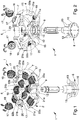
Figure 1 is an exploded view of the head according to the invention; -
Figure 2 is an exploded view from another angle of the head according to the invention; -
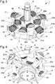
Figure 3 is an axonometric view from above of the head according to the invention; -
Figure 4 is an axonometric view from below of the head according to the invention; -
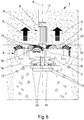
Figure 5 is a front view of the head according to the invention. - With particular reference to such figures,
reference number 1 globally indicates an excavating head. - The
head 1, in particular, allows performing dry excavations. - In the context of this treatise by "dry excavations" are meant excavations that take place in the absence of water, or in terrestrial conditions in the absence of water tables.
- The
head 1 comprises a plate-shaped body 2 having a firstmain face 3 and a secondmain face 4 opposite to each other. - With reference to the particular embodiment shown in the illustrations, the first
main face 3 is facing to the excavation front. - In the context of this treatise by "excavation front" is meant the margin defined by the material to be excavated, along the direction of
excavation 5 defined by acentral axis 6 of thehead 1. - Preferably, the
central axis 6 is vertical and the direction of excavation is upwards. - Advantageously, the plate-
shaped body 2 is substantially perpendicular to thecentral axis 6. - Furthermore, it is specified that in the present treatise expressions such as "high", "low", "upper", "lower", "above", "below" and the like, are to be deemed with reference to an operative configuration wherein the
head 1 is used for upward vertical excavations. - However, it cannot be ruled out that the direction of
excavation 5 be horizontal, in which case thehead 1 is used in an operative configuration wherein thecentral axis 6 is horizontal. - In the operative configuration, shown in the illustrations, wherein the
central axis 6 is vertical, the plate-shaped body 2 is substantially horizontal and the firstmain face 3 is above the secondmain face 4. - With reference to the particular embodiment shown in the illustrations, the plate-
shaped body 2 has a substantially circular perimeter. - It is specified that, in the present treatise, by the term "perimeter" is meant an imaginary circumference arranged on the
margin 7 of the plate-shaped body 2. Thehead 1 comprises anattachment element 8 to a driving machine to place the head itself in rotation. - The placing in rotation of the
head 1 takes place along the direction ofexcavation 5, around thecentral axis 6. - With reference to the particular embodiment shown in the illustrations, the
attachment element 8 has a substantially tubular shape and coincides with thecentral axis 6. - Advantageously, the
attachment element 8 has afirst extremity 9 for the connection to the driving machine and asecond extremity 10 joining to the plate-shaped body 2. - In the present case, the
first extremity 9 can be coupled to acorresponding coupling element 11, such as, e.g., a telescopic arm, equipping the driving machine. - The
second extremity 10 comprises a flanged plate that is connectable to anattachment flange 12 associated with the secondmain face 4. - In this regard, it is pointed out that the first
main face 3 is directed towards thefirst extremity 9 and the secondmain face 4 is directed towards thesecond extremity 10. - In detail, the
flanged plate 10 is connected to theattachment flange 12 by means of joiningelements 13 of the type of screws, bolts or the like, which can be fitted into corresponding boltingholes 14 equipping theattachment flange 12. Conveniently, theattachment flange 12 is associated with the secondmain face 4 by interposition of a plurality of reinforcingribs 15. - Furthermore, the
head 1 comprises acentral hole 16 crossing the plate-shaped body 2 between the firstmain face 3 and the secondmain face 4. - With reference to the particular embodiment shown in the illustrations, the
attachment element 8 is housed at least partly in thecentral hole 16 so as to cross the plate-shaped body 2 from side to side, so that thefirst extremity 9 emerges from the firstmain face 3 and thesecond extremity 10 emerges from the secondmain face 4. - The
head 1 comprises at least anexcavation tool 17 associated with the plate-shaped body 2 so as to protrude at least in part from the firstmain face 3. Advantageously, the plate-shaped body 2 comprises a plurality ofexcavation tools 17. - The
excavation tools 17 have variable shape and size according to the type and dimensions of the excavation. - With reference to the particular embodiment shown in the illustrations, the
excavation tools 17 are composed of a substantially cylindrical or frusto-conical body having a sharp or abrasive outer surface. - Conveniently, the
excavation tools 17 are mounted idle on the plate-shaped body 2. - In the present case, each
excavation tool 17 is associated with the plate-shaped body 2 by means ofaxial pins 18 separate and parallel to each other which allow its free rotation around a central axis of symmetry of theexcavation tool 17. - With reference to the particular embodiment shown in the illustrations, the
excavation tools 17 are arranged symmetrically with respect to thecentral axis 6 and have rotation axes with different inclinations according to their position on the plate-shaped body 2. - It cannot however be ruled out that the
aforementioned excavation tools 17 be arranged asymmetrically with respect to thecentral axis 6. - Advantageously, the
excavation tools 17 define anexcavation plane 19 tangent to the excavation tools themselves. - The
excavation plane 19, in practice, consists in an imaginary plane which, in the operative configuration of thehead 1, is substantially horizontal and tangent to the upper part of eachexcavation tool 17. - Furthermore, the
head 1 comprises at least a through opening 20 and crossing the plate-shaped body 2 between the firstmain face 3 and the secondmain face 4, within which acorresponding excavation tool 17 is at least partially housed. Advantageously, thehead 1 which comprises a plurality ofexcavation tools 17, also comprises a plurality of throughopenings 20, wherein eachexcavation tool 17 is at least partially housed within one of the throughopenings 20. - In particular, each
excavation tool 17 is at least partially housed within one and only one corresponding through opening 20 and emerges (i.e. protrudes) from the firstmain face 3 for at least one-twentieth of its volume. - Advantageously, the
axial pins 18 of theexcavation tools 17 are arranged inside the throughopenings 20 and the material excavated by theexcavation tools 17 is able to cross the plate-shaped body 2, passing in the space defined between theexcavation tools 17 and the inner walls of thethrough openings 20. - It is easy to appreciate how the presence of the through
openings 20 in which theexcavation tools 17 are housed facilitates the fall of the excavated material, determining an increase in the flow rate of the exiting material and an increase in the speed of excavation, in addition to averting the risk of the excavated material accumulating between theexcavation tools 17 and the plate-shaped body 2. - The
head 1 comprises at least a throughslot shaped body 2 between the firstmain face 3 and the secondmain face 4 and which is shaped by theexcavation tools 17. - Advantageously, the
head 1 comprises a plurality of throughslots - With reference to the particular embodiment shown in the illustrations for example, the through
slots slots 21a having a substantially openfirst edge 22a and a plurality of second throughslots 21b having a substantially closedsecond edge 22b. - Advantageously, the first through
slots 21a are formed on the perimeter of the plate-shapedbody 2, whereas the second throughslots 21b are spaced apart with respect to the perimeter of the plate-shapedbody 2. - With reference to the particular embodiment shown in the illustrations, the first through
slots 21a are obtained from a recess of the substantially circular perimeter of the plate-shapedbody 2, whereas the second throughslots 21b have a substantially circular shape. - Advantageously, the through
slots central axis 6. - Nonetheless, alternative embodiments cannot be ruled out wherein the above-mentioned through
slots central axis 6. - It is easy to appreciate how the presence of the through
slots - The operation of the present invention is as follows.
- The
head 1 is made to rotate by the operation of the driving machine. - The
excavation tools 17 are operated in rotation by means of the pressure of thehead 1 against the excavation front. - Simultaneously the excavated material, passing through the through
openings 20 and the throughslots excavation 5. - It has in practice been ascertained how the described invention achieves the intended objects.
- In particular, the fact is underlined that the particular solution of providing a plurality of through openings, formed through the plate-shaped body and housing the excavation tools, permits increasing the amount of material exiting in the unit of time and greatly increases the productivity of the excavating head.
Claims (12)
- Excavating head (1) comprising:- at least an attachment element (8) to a driving machine to place said head (1) in rotation;- at least a plate-shaped body (2) connected to said attachment element (8) and having at least a first main face (3) and at least a second main face (4) opposite to each other, said first main face (3) being facing to the excavation front; and- at least an excavation tool (17) associated with said plate-shaped body (2) so as to protrude at least in part from said first main face (3);- least a through opening (20) and crossing said plate-shaped body (2) between said first main face (3) and said second main face (4), said excavation tool (17) being at least partially housed within said through opening (20);characterized by the fact that said attachment element (8) has a first extremity (9) for the connection to said driving machine, said first main face (3) being directed towards said first extremity (9).
- Head (1) according to claim 1, characterized by the fact that said excavation tool (17) emerges from said first main face (3) for at least one-twentieth of its volume.
- Head (1) according to one or more of the preceding claims, characterized by the fact that it comprises a plurality of said through openings (20) and a plurality of said excavation tools (17), each of which is at least partially housed within one of said through openings (20).
- Head (1) according to one or more of the preceding claims, characterized by the fact that said plate-shaped body (2) has a substantially circular perimeter and is substantially perpendicular to a central axis (6).
- Head (1) according to one or more of the preceding claims, characterized by the fact that said attachment element (8) has a substantially tubular shape and coincides with said central axis (6).
- Head (1) according to one or more of the preceding claims, characterized by the fact that said attachment element (8) has a second extremity (10) joining to said plate-shaped body (2), said second main face (4) being directed towards said second extremity (10).
- Head (1) according to one or more of the preceding claims, characterized by the fact that said second extremity (10) comprises a flanged plate that is connectable to an attachment flange (12) associated with said second main face (4).
- Head (1) according to one or more of the preceding claims, characterized by the fact that said attachment flange (12) is associated with said second main face (4) by interposition of a plurality of reinforcing ribs (15).
- Head (1) according to one or more of the preceding claims, characterized by the fact that it comprises a central hole (16) and crossing said plate-shaped body (2) between said first main face (3) and said second main face (4), said attachment element (8) being housed at least partly in said central hole (16) so as to cross from side to side said plate-shaped body (2) with said first extremity (9) that emerges from said first main face (3) and said second extremity (10) that emerges from said second main face (4).
- Head (1) according to one or more of the preceding claims, characterized by the fact that it comprises at least a through slot (21a, 21b) and crossing said plate-shaped body (2) between said first main face (3) and said second main face (4), said through slot (21a, 21b) being clear of said excavation tools (17).
- Head (1) according to one or more of the preceding claims, characterized by the fact that said through slot (21a, 21b) has a substantially open edge and is formed on said perimeter of the plate-shaped body (2).
- Head (1) according to one or more of the preceding claims, characterized by the fact that said through slot (21a, 21b) has a substantially closed edge and is spaced apart with respect to said perimeter of the plate-shaped body (2).
Applications Claiming Priority (2)
| Application Number | Priority Date | Filing Date | Title |
|---|---|---|---|
| ITMO20150054 | 2015-03-12 | ||
| PCT/IB2016/051385 WO2016142908A1 (en) | 2015-03-12 | 2016-03-11 | Excavating head |
Publications (2)
| Publication Number | Publication Date |
|---|---|
| EP3268570A1 EP3268570A1 (en) | 2018-01-17 |
| EP3268570B1 true EP3268570B1 (en) | 2019-05-08 |
Family
ID=53177801
Family Applications (1)
| Application Number | Title | Priority Date | Filing Date |
|---|---|---|---|
| EP16717704.7A Not-in-force EP3268570B1 (en) | 2015-03-12 | 2016-03-11 | Excavating head |
Country Status (2)
| Country | Link |
|---|---|
| EP (1) | EP3268570B1 (en) |
| WO (1) | WO2016142908A1 (en) |
Families Citing this family (1)
| Publication number | Priority date | Publication date | Assignee | Title |
|---|---|---|---|---|
| CN113982591B (en) * | 2021-10-22 | 2022-06-14 | 核工业井巷建设集团有限公司 | Large-diameter deep shaft reverse excavation device and construction method |
Citations (12)
| Publication number | Priority date | Publication date | Assignee | Title |
|---|---|---|---|---|
| DE2837038A1 (en) | 1977-09-09 | 1979-03-29 | Sandvik Ab | DRILL HEAD FOR AN EXTENSION DRILL FOR UPWARD DRILLING |
| WO1980001587A1 (en) | 1979-02-05 | 1980-08-07 | Robbins Co | Rotary cutterhead for an earth boring machine |
| DE3001788A1 (en) | 1979-02-02 | 1980-08-14 | Sandvik Ab | METHOD FOR CHANGING THE DISTANCE ON A DRILL HEAD AND DRILL HEAD, PREFERRED FOR EARTH HOLES |
| US4381038A (en) | 1980-11-21 | 1983-04-26 | The Robbins Company | Raise bit with cutters stepped in a spiral and flywheel |
| US4784438A (en) | 1986-02-20 | 1988-11-15 | Fikse Tyman H | Tunneling machine rotatable member |
| US5096022A (en) | 1988-11-17 | 1992-03-17 | Charles E. Bowers | Theft-proof flag locking system |
| WO1998003765A1 (en) | 1996-07-19 | 1998-01-29 | Friant James E | Improved disc cutter and excavation equipment |
| WO2000050738A1 (en) | 1999-02-25 | 2000-08-31 | Wirth Maschinen- und Bohrgeräte-Fabrik GmbH | Advancing device for boring sections of roadway, tunnels or similar |
| DE19808478C2 (en) | 1998-03-02 | 2000-10-26 | Ruediger Koegler | Process for trenchless laying of pipes |
| WO2011043987A2 (en) | 2009-10-06 | 2011-04-14 | Baker Hughes Incorporated | Hole opener with hybrid reaming section |
| DE102012004762A1 (en) | 2012-03-08 | 2013-09-12 | Rüdiger Kögler | Device for expanding bore hole up to large diameter, has delivery line extending from region of cutting wheel inside machine pipe, and outlet located in rear portion of machine pipe, where support plate is connected with machine pipe |
| WO2014078660A1 (en) | 2012-11-15 | 2014-05-22 | Vermeer Manufacturing Company | Push reamer |
-
2016
- 2016-03-11 WO PCT/IB2016/051385 patent/WO2016142908A1/en not_active Ceased
- 2016-03-11 EP EP16717704.7A patent/EP3268570B1/en not_active Not-in-force
Patent Citations (14)
| Publication number | Priority date | Publication date | Assignee | Title |
|---|---|---|---|---|
| DE2837038A1 (en) | 1977-09-09 | 1979-03-29 | Sandvik Ab | DRILL HEAD FOR AN EXTENSION DRILL FOR UPWARD DRILLING |
| US4228863A (en) | 1977-09-09 | 1980-10-21 | Sandvik Aktiebolag | Reamer bit for raise boring |
| DE3001788A1 (en) | 1979-02-02 | 1980-08-14 | Sandvik Ab | METHOD FOR CHANGING THE DISTANCE ON A DRILL HEAD AND DRILL HEAD, PREFERRED FOR EARTH HOLES |
| US4274496A (en) | 1979-02-02 | 1981-06-23 | Sandvik Aktiebolag | Method and device in earth cutting |
| WO1980001587A1 (en) | 1979-02-05 | 1980-08-07 | Robbins Co | Rotary cutterhead for an earth boring machine |
| US4381038A (en) | 1980-11-21 | 1983-04-26 | The Robbins Company | Raise bit with cutters stepped in a spiral and flywheel |
| US4784438A (en) | 1986-02-20 | 1988-11-15 | Fikse Tyman H | Tunneling machine rotatable member |
| US5096022A (en) | 1988-11-17 | 1992-03-17 | Charles E. Bowers | Theft-proof flag locking system |
| WO1998003765A1 (en) | 1996-07-19 | 1998-01-29 | Friant James E | Improved disc cutter and excavation equipment |
| DE19808478C2 (en) | 1998-03-02 | 2000-10-26 | Ruediger Koegler | Process for trenchless laying of pipes |
| WO2000050738A1 (en) | 1999-02-25 | 2000-08-31 | Wirth Maschinen- und Bohrgeräte-Fabrik GmbH | Advancing device for boring sections of roadway, tunnels or similar |
| WO2011043987A2 (en) | 2009-10-06 | 2011-04-14 | Baker Hughes Incorporated | Hole opener with hybrid reaming section |
| DE102012004762A1 (en) | 2012-03-08 | 2013-09-12 | Rüdiger Kögler | Device for expanding bore hole up to large diameter, has delivery line extending from region of cutting wheel inside machine pipe, and outlet located in rear portion of machine pipe, where support plate is connected with machine pipe |
| WO2014078660A1 (en) | 2012-11-15 | 2014-05-22 | Vermeer Manufacturing Company | Push reamer |
Also Published As
| Publication number | Publication date |
|---|---|
| WO2016142908A1 (en) | 2016-09-15 |
| EP3268570A1 (en) | 2018-01-17 |
Similar Documents
| Publication | Publication Date | Title |
|---|---|---|
| KR101596926B1 (en) | Multi-core barrel hammer system | |
| EP3268570B1 (en) | Excavating head | |
| KR20150130089A (en) | Shaft excavation apparatus | |
| EP3268569B1 (en) | Excavating head | |
| KR20150000245A (en) | Apparatus for excavating | |
| CN104453925A (en) | Abnormal-shaped pipe-jacking tunneling machine | |
| KR101582166B1 (en) | Excavating bit having air-hammer and screw for excavating ground composed by earth, sand, soft rock and boulder | |
| AU2020358126B2 (en) | Liquid hammer drill | |
| KR20110105508A (en) | Stone quarry workhole driller | |
| CN208203133U (en) | A kind of rotary digging cutter barrel brill | |
| US7708087B2 (en) | Countersink roof bit drill and method for using the same | |
| KR101576973B1 (en) | Reverse Circulation Drill System | |
| CN105922460B (en) | A kind of punching component for construction material | |
| CN206830181U (en) | A kind of tunnel piercing rounding machine cutter for being used to automate cutter changing | |
| CN212506457U (en) | Forced landing rectification device capable of accurately and directionally disturbing foundation | |
| CN111622282B (en) | Multifunctional jet drilling tool, forced landing and inclination correcting equipment capable of realizing precise directional disturbance and forced landing and inclination correcting method | |
| KR101528775B1 (en) | Percussion rotary drill rod of excavating apparatus | |
| CN108643180A (en) | A kind of stake device processed that architectural engineering uses | |
| EP3268568B1 (en) | Excavating head | |
| CN202131625U (en) | Pneumatic grooving drill | |
| CN112065417A (en) | Center-protruded anti-caking cutter head | |
| EP2675982B1 (en) | Method and apparatus for down-the-hole drilling | |
| KR101608969B1 (en) | Bit for drilling apparatus | |
| KR20200092594A (en) | Fixing device for disassembling core bit | |
| CN210217635U (en) | Drill stand and combined drill body |
Legal Events
| Date | Code | Title | Description |
|---|---|---|---|
| STAA | Information on the status of an ep patent application or granted ep patent |
Free format text: STATUS: THE INTERNATIONAL PUBLICATION HAS BEEN MADE |
|
| PUAI | Public reference made under article 153(3) epc to a published international application that has entered the european phase |
Free format text: ORIGINAL CODE: 0009012 |
|
| STAA | Information on the status of an ep patent application or granted ep patent |
Free format text: STATUS: REQUEST FOR EXAMINATION WAS MADE |
|
| 17P | Request for examination filed |
Effective date: 20171011 |
|
| AK | Designated contracting states |
Kind code of ref document: A1 Designated state(s): AL AT BE BG CH CY CZ DE DK EE ES FI FR GB GR HR HU IE IS IT LI LT LU LV MC MK MT NL NO PL PT RO RS SE SI SK SM TR |
|
| AX | Request for extension of the european patent |
Extension state: BA ME |
|
| DAV | Request for validation of the european patent (deleted) | ||
| DAX | Request for extension of the european patent (deleted) | ||
| REG | Reference to a national code |
Ref country code: DE Ref legal event code: R079 Ref document number: 602016013655 Country of ref document: DE Free format text: PREVIOUS MAIN CLASS: E21B0007280000 Ipc: E21D0003000000 |
|
| GRAP | Despatch of communication of intention to grant a patent |
Free format text: ORIGINAL CODE: EPIDOSNIGR1 |
|
| STAA | Information on the status of an ep patent application or granted ep patent |
Free format text: STATUS: GRANT OF PATENT IS INTENDED |
|
| RIC1 | Information provided on ipc code assigned before grant |
Ipc: E21D 3/00 20060101AFI20180914BHEP Ipc: E21B 7/28 20060101ALI20180914BHEP Ipc: E21B 10/08 20060101ALI20180914BHEP |
|
| INTG | Intention to grant announced |
Effective date: 20181009 |
|
| GRAS | Grant fee paid |
Free format text: ORIGINAL CODE: EPIDOSNIGR3 |
|
| GRAA | (expected) grant |
Free format text: ORIGINAL CODE: 0009210 |
|
| STAA | Information on the status of an ep patent application or granted ep patent |
Free format text: STATUS: THE PATENT HAS BEEN GRANTED |
|
| AK | Designated contracting states |
Kind code of ref document: B1 Designated state(s): AL AT BE BG CH CY CZ DE DK EE ES FI FR GB GR HR HU IE IS IT LI LT LU LV MC MK MT NL NO PL PT RO RS SE SI SK SM TR |
|
| REG | Reference to a national code |
Ref country code: GB Ref legal event code: FG4D |
|
| REG | Reference to a national code |
Ref country code: AT Ref legal event code: REF Ref document number: 1130403 Country of ref document: AT Kind code of ref document: T Effective date: 20190515 Ref country code: CH Ref legal event code: EP |
|
| REG | Reference to a national code |
Ref country code: IE Ref legal event code: FG4D |
|
| REG | Reference to a national code |
Ref country code: DE Ref legal event code: R096 Ref document number: 602016013655 Country of ref document: DE |
|
| REG | Reference to a national code |
Ref country code: NL Ref legal event code: MP Effective date: 20190508 |
|
| REG | Reference to a national code |
Ref country code: LT Ref legal event code: MG4D |
|
| PG25 | Lapsed in a contracting state [announced via postgrant information from national office to epo] |
Ref country code: LT Free format text: LAPSE BECAUSE OF FAILURE TO SUBMIT A TRANSLATION OF THE DESCRIPTION OR TO PAY THE FEE WITHIN THE PRESCRIBED TIME-LIMIT Effective date: 20190508 Ref country code: FI Free format text: LAPSE BECAUSE OF FAILURE TO SUBMIT A TRANSLATION OF THE DESCRIPTION OR TO PAY THE FEE WITHIN THE PRESCRIBED TIME-LIMIT Effective date: 20190508 Ref country code: PT Free format text: LAPSE BECAUSE OF FAILURE TO SUBMIT A TRANSLATION OF THE DESCRIPTION OR TO PAY THE FEE WITHIN THE PRESCRIBED TIME-LIMIT Effective date: 20190908 Ref country code: AL Free format text: LAPSE BECAUSE OF FAILURE TO SUBMIT A TRANSLATION OF THE DESCRIPTION OR TO PAY THE FEE WITHIN THE PRESCRIBED TIME-LIMIT Effective date: 20190508 Ref country code: NO Free format text: LAPSE BECAUSE OF FAILURE TO SUBMIT A TRANSLATION OF THE DESCRIPTION OR TO PAY THE FEE WITHIN THE PRESCRIBED TIME-LIMIT Effective date: 20190808 Ref country code: HR Free format text: LAPSE BECAUSE OF FAILURE TO SUBMIT A TRANSLATION OF THE DESCRIPTION OR TO PAY THE FEE WITHIN THE PRESCRIBED TIME-LIMIT Effective date: 20190508 Ref country code: ES Free format text: LAPSE BECAUSE OF FAILURE TO SUBMIT A TRANSLATION OF THE DESCRIPTION OR TO PAY THE FEE WITHIN THE PRESCRIBED TIME-LIMIT Effective date: 20190508 Ref country code: NL Free format text: LAPSE BECAUSE OF FAILURE TO SUBMIT A TRANSLATION OF THE DESCRIPTION OR TO PAY THE FEE WITHIN THE PRESCRIBED TIME-LIMIT Effective date: 20190508 Ref country code: SE Free format text: LAPSE BECAUSE OF FAILURE TO SUBMIT A TRANSLATION OF THE DESCRIPTION OR TO PAY THE FEE WITHIN THE PRESCRIBED TIME-LIMIT Effective date: 20190508 |
|
| PG25 | Lapsed in a contracting state [announced via postgrant information from national office to epo] |
Ref country code: LV Free format text: LAPSE BECAUSE OF FAILURE TO SUBMIT A TRANSLATION OF THE DESCRIPTION OR TO PAY THE FEE WITHIN THE PRESCRIBED TIME-LIMIT Effective date: 20190508 Ref country code: BG Free format text: LAPSE BECAUSE OF FAILURE TO SUBMIT A TRANSLATION OF THE DESCRIPTION OR TO PAY THE FEE WITHIN THE PRESCRIBED TIME-LIMIT Effective date: 20190808 Ref country code: RS Free format text: LAPSE BECAUSE OF FAILURE TO SUBMIT A TRANSLATION OF THE DESCRIPTION OR TO PAY THE FEE WITHIN THE PRESCRIBED TIME-LIMIT Effective date: 20190508 Ref country code: GR Free format text: LAPSE BECAUSE OF FAILURE TO SUBMIT A TRANSLATION OF THE DESCRIPTION OR TO PAY THE FEE WITHIN THE PRESCRIBED TIME-LIMIT Effective date: 20190809 |
|
| REG | Reference to a national code |
Ref country code: AT Ref legal event code: MK05 Ref document number: 1130403 Country of ref document: AT Kind code of ref document: T Effective date: 20190508 |
|
| PG25 | Lapsed in a contracting state [announced via postgrant information from national office to epo] |
Ref country code: CZ Free format text: LAPSE BECAUSE OF FAILURE TO SUBMIT A TRANSLATION OF THE DESCRIPTION OR TO PAY THE FEE WITHIN THE PRESCRIBED TIME-LIMIT Effective date: 20190508 Ref country code: SK Free format text: LAPSE BECAUSE OF FAILURE TO SUBMIT A TRANSLATION OF THE DESCRIPTION OR TO PAY THE FEE WITHIN THE PRESCRIBED TIME-LIMIT Effective date: 20190508 Ref country code: RO Free format text: LAPSE BECAUSE OF FAILURE TO SUBMIT A TRANSLATION OF THE DESCRIPTION OR TO PAY THE FEE WITHIN THE PRESCRIBED TIME-LIMIT Effective date: 20190508 Ref country code: EE Free format text: LAPSE BECAUSE OF FAILURE TO SUBMIT A TRANSLATION OF THE DESCRIPTION OR TO PAY THE FEE WITHIN THE PRESCRIBED TIME-LIMIT Effective date: 20190508 Ref country code: DK Free format text: LAPSE BECAUSE OF FAILURE TO SUBMIT A TRANSLATION OF THE DESCRIPTION OR TO PAY THE FEE WITHIN THE PRESCRIBED TIME-LIMIT Effective date: 20190508 Ref country code: AT Free format text: LAPSE BECAUSE OF FAILURE TO SUBMIT A TRANSLATION OF THE DESCRIPTION OR TO PAY THE FEE WITHIN THE PRESCRIBED TIME-LIMIT Effective date: 20190508 |
|
| REG | Reference to a national code |
Ref country code: DE Ref legal event code: R026 Ref document number: 602016013655 Country of ref document: DE |
|
| PLBI | Opposition filed |
Free format text: ORIGINAL CODE: 0009260 |
|
| PLAX | Notice of opposition and request to file observation + time limit sent |
Free format text: ORIGINAL CODE: EPIDOSNOBS2 |
|
| PG25 | Lapsed in a contracting state [announced via postgrant information from national office to epo] |
Ref country code: SM Free format text: LAPSE BECAUSE OF FAILURE TO SUBMIT A TRANSLATION OF THE DESCRIPTION OR TO PAY THE FEE WITHIN THE PRESCRIBED TIME-LIMIT Effective date: 20190508 Ref country code: IT Free format text: LAPSE BECAUSE OF FAILURE TO SUBMIT A TRANSLATION OF THE DESCRIPTION OR TO PAY THE FEE WITHIN THE PRESCRIBED TIME-LIMIT Effective date: 20190508 |
|
| 26 | Opposition filed |
Opponent name: HERRENKNECHT AKTIENGESELLSCHAFT Effective date: 20200210 |
|
| PG25 | Lapsed in a contracting state [announced via postgrant information from national office to epo] |
Ref country code: TR Free format text: LAPSE BECAUSE OF FAILURE TO SUBMIT A TRANSLATION OF THE DESCRIPTION OR TO PAY THE FEE WITHIN THE PRESCRIBED TIME-LIMIT Effective date: 20190508 |
|
| PG25 | Lapsed in a contracting state [announced via postgrant information from national office to epo] |
Ref country code: PL Free format text: LAPSE BECAUSE OF FAILURE TO SUBMIT A TRANSLATION OF THE DESCRIPTION OR TO PAY THE FEE WITHIN THE PRESCRIBED TIME-LIMIT Effective date: 20190508 |
|
| PG25 | Lapsed in a contracting state [announced via postgrant information from national office to epo] |
Ref country code: SI Free format text: LAPSE BECAUSE OF FAILURE TO SUBMIT A TRANSLATION OF THE DESCRIPTION OR TO PAY THE FEE WITHIN THE PRESCRIBED TIME-LIMIT Effective date: 20190508 |
|
| REG | Reference to a national code |
Ref country code: DE Ref legal event code: R119 Ref document number: 602016013655 Country of ref document: DE |
|
| PG25 | Lapsed in a contracting state [announced via postgrant information from national office to epo] |
Ref country code: MC Free format text: LAPSE BECAUSE OF FAILURE TO SUBMIT A TRANSLATION OF THE DESCRIPTION OR TO PAY THE FEE WITHIN THE PRESCRIBED TIME-LIMIT Effective date: 20190508 |
|
| REG | Reference to a national code |
Ref country code: CH Ref legal event code: PL |
|
| REG | Reference to a national code |
Ref country code: BE Ref legal event code: MM Effective date: 20200331 |
|
| PG25 | Lapsed in a contracting state [announced via postgrant information from national office to epo] |
Ref country code: LU Free format text: LAPSE BECAUSE OF NON-PAYMENT OF DUE FEES Effective date: 20200311 |
|
| PG25 | Lapsed in a contracting state [announced via postgrant information from national office to epo] |
Ref country code: IE Free format text: LAPSE BECAUSE OF NON-PAYMENT OF DUE FEES Effective date: 20200311 Ref country code: FR Free format text: LAPSE BECAUSE OF NON-PAYMENT OF DUE FEES Effective date: 20200331 Ref country code: CH Free format text: LAPSE BECAUSE OF NON-PAYMENT OF DUE FEES Effective date: 20200331 Ref country code: LI Free format text: LAPSE BECAUSE OF NON-PAYMENT OF DUE FEES Effective date: 20200331 Ref country code: DE Free format text: LAPSE BECAUSE OF NON-PAYMENT OF DUE FEES Effective date: 20201001 |
|
| PG25 | Lapsed in a contracting state [announced via postgrant information from national office to epo] |
Ref country code: BE Free format text: LAPSE BECAUSE OF NON-PAYMENT OF DUE FEES Effective date: 20200331 |
|
| GBPC | Gb: european patent ceased through non-payment of renewal fee |
Effective date: 20200311 |
|
| PG25 | Lapsed in a contracting state [announced via postgrant information from national office to epo] |
Ref country code: GB Free format text: LAPSE BECAUSE OF NON-PAYMENT OF DUE FEES Effective date: 20200311 |
|
| PG25 | Lapsed in a contracting state [announced via postgrant information from national office to epo] |
Ref country code: HU Free format text: LAPSE BECAUSE OF FAILURE TO SUBMIT A TRANSLATION OF THE DESCRIPTION OR TO PAY THE FEE WITHIN THE PRESCRIBED TIME-LIMIT; INVALID AB INITIO Effective date: 20160311 Ref country code: MK Free format text: LAPSE BECAUSE OF FAILURE TO SUBMIT A TRANSLATION OF THE DESCRIPTION OR TO PAY THE FEE WITHIN THE PRESCRIBED TIME-LIMIT Effective date: 20190508 Ref country code: IS Free format text: LAPSE BECAUSE OF FAILURE TO SUBMIT A TRANSLATION OF THE DESCRIPTION OR TO PAY THE FEE WITHIN THE PRESCRIBED TIME-LIMIT Effective date: 20190508 Ref country code: CY Free format text: LAPSE BECAUSE OF NON-PAYMENT OF DUE FEES Effective date: 20190508 Ref country code: MT Free format text: LAPSE BECAUSE OF FAILURE TO SUBMIT A TRANSLATION OF THE DESCRIPTION OR TO PAY THE FEE WITHIN THE PRESCRIBED TIME-LIMIT Effective date: 20190508 |
|
| PLBD | Termination of opposition procedure: decision despatched |
Free format text: ORIGINAL CODE: EPIDOSNOPC1 |
|
| REG | Reference to a national code |
Ref country code: DE Ref legal event code: R100 Ref document number: 602016013655 Country of ref document: DE |
|
| PLBM | Termination of opposition procedure: date of legal effect published |
Free format text: ORIGINAL CODE: 0009276 |
|
| 27C | Opposition proceedings terminated |
Effective date: 20220117 |