EP3268053B1 - Multiple-bore solute cartridge carrier - Google Patents
Multiple-bore solute cartridge carrier Download PDFInfo
- Publication number
- EP3268053B1 EP3268053B1 EP16712609.3A EP16712609A EP3268053B1 EP 3268053 B1 EP3268053 B1 EP 3268053B1 EP 16712609 A EP16712609 A EP 16712609A EP 3268053 B1 EP3268053 B1 EP 3268053B1
- Authority
- EP
- European Patent Office
- Prior art keywords
- bore
- solute
- delivery system
- fluid delivery
- cartridge carrier
- Prior art date
- Legal status (The legal status is an assumption and is not a legal conclusion. Google has not performed a legal analysis and makes no representation as to the accuracy of the status listed.)
- Active
Links
Images




Classifications
-
- C—CHEMISTRY; METALLURGY
- C02—TREATMENT OF WATER, WASTE WATER, SEWAGE, OR SLUDGE
- C02F—TREATMENT OF WATER, WASTE WATER, SEWAGE, OR SLUDGE
- C02F1/00—Treatment of water, waste water, or sewage
- C02F1/68—Treatment of water, waste water, or sewage by addition of specified substances, e.g. trace elements, for ameliorating potable water
- C02F1/685—Devices for dosing the additives
- C02F1/687—Devices for dosing solid compounds
-
- C—CHEMISTRY; METALLURGY
- C02—TREATMENT OF WATER, WASTE WATER, SEWAGE, OR SLUDGE
- C02F—TREATMENT OF WATER, WASTE WATER, SEWAGE, OR SLUDGE
- C02F9/00—Multistage treatment of water, waste water or sewage
- C02F9/20—Portable or detachable small-scale multistage treatment devices, e.g. point of use or laboratory water purification systems
-
- A—HUMAN NECESSITIES
- A61—MEDICAL OR VETERINARY SCIENCE; HYGIENE
- A61G—TRANSPORT, PERSONAL CONVEYANCES, OR ACCOMMODATION SPECIALLY ADAPTED FOR PATIENTS OR DISABLED PERSONS; OPERATING TABLES OR CHAIRS; CHAIRS FOR DENTISTRY; FUNERAL DEVICES
- A61G12/00—Accommodation for nursing, e.g. in hospitals, not covered by groups A61G1/00 - A61G11/00, e.g. trolleys for transport of medicaments or food; Prescription lists
- A61G12/001—Trolleys for transport of medicaments, food, linen, nursing supplies
-
- A—HUMAN NECESSITIES
- A61—MEDICAL OR VETERINARY SCIENCE; HYGIENE
- A61G—TRANSPORT, PERSONAL CONVEYANCES, OR ACCOMMODATION SPECIALLY ADAPTED FOR PATIENTS OR DISABLED PERSONS; OPERATING TABLES OR CHAIRS; CHAIRS FOR DENTISTRY; FUNERAL DEVICES
- A61G12/00—Accommodation for nursing, e.g. in hospitals, not covered by groups A61G1/00 - A61G11/00, e.g. trolleys for transport of medicaments or food; Prescription lists
- A61G12/002—Supply appliances, e.g. columns for gas, fluid, electricity supply
- A61G12/008—Supply appliances, e.g. columns for gas, fluid, electricity supply mounted on a mobile base, e.g. on a trolley
-
- A—HUMAN NECESSITIES
- A61—MEDICAL OR VETERINARY SCIENCE; HYGIENE
- A61L—METHODS OR APPARATUS FOR STERILISING MATERIALS OR OBJECTS IN GENERAL; DISINFECTION, STERILISATION OR DEODORISATION OF AIR; CHEMICAL ASPECTS OF BANDAGES, DRESSINGS, ABSORBENT PADS OR SURGICAL ARTICLES; MATERIALS FOR BANDAGES, DRESSINGS, ABSORBENT PADS OR SURGICAL ARTICLES
- A61L2/00—Disinfection or sterilisation of materials or objects, in general; Accessories therefor
- A61L2/02—Disinfection or sterilisation of materials or objects, in general; Accessories therefor using physical processes
- A61L2/022—Filtration
-
- A—HUMAN NECESSITIES
- A61—MEDICAL OR VETERINARY SCIENCE; HYGIENE
- A61L—METHODS OR APPARATUS FOR STERILISING MATERIALS OR OBJECTS IN GENERAL; DISINFECTION, STERILISATION OR DEODORISATION OF AIR; CHEMICAL ASPECTS OF BANDAGES, DRESSINGS, ABSORBENT PADS OR SURGICAL ARTICLES; MATERIALS FOR BANDAGES, DRESSINGS, ABSORBENT PADS OR SURGICAL ARTICLES
- A61L2/00—Disinfection or sterilisation of materials or objects, in general; Accessories therefor
- A61L2/26—Accessories
-
- A—HUMAN NECESSITIES
- A61—MEDICAL OR VETERINARY SCIENCE; HYGIENE
- A61L—METHODS OR APPARATUS FOR STERILISING MATERIALS OR OBJECTS IN GENERAL; DISINFECTION, STERILISATION OR DEODORISATION OF AIR; CHEMICAL ASPECTS OF BANDAGES, DRESSINGS, ABSORBENT PADS OR SURGICAL ARTICLES; MATERIALS FOR BANDAGES, DRESSINGS, ABSORBENT PADS OR SURGICAL ARTICLES
- A61L9/00—Disinfection, sterilisation or deodorisation of air
-
- C—CHEMISTRY; METALLURGY
- C02—TREATMENT OF WATER, WASTE WATER, SEWAGE, OR SLUDGE
- C02F—TREATMENT OF WATER, WASTE WATER, SEWAGE, OR SLUDGE
- C02F1/00—Treatment of water, waste water, or sewage
- C02F1/008—Control or steering systems not provided for elsewhere in subclass C02F
-
- C—CHEMISTRY; METALLURGY
- C02—TREATMENT OF WATER, WASTE WATER, SEWAGE, OR SLUDGE
- C02F—TREATMENT OF WATER, WASTE WATER, SEWAGE, OR SLUDGE
- C02F1/00—Treatment of water, waste water, or sewage
- C02F1/30—Treatment of water, waste water, or sewage by irradiation
- C02F1/32—Treatment of water, waste water, or sewage by irradiation with ultraviolet light
- C02F1/325—Irradiation devices or lamp constructions
-
- C—CHEMISTRY; METALLURGY
- C02—TREATMENT OF WATER, WASTE WATER, SEWAGE, OR SLUDGE
- C02F—TREATMENT OF WATER, WASTE WATER, SEWAGE, OR SLUDGE
- C02F1/00—Treatment of water, waste water, or sewage
- C02F1/46—Treatment of water, waste water, or sewage by electrochemical methods
- C02F1/469—Treatment of water, waste water, or sewage by electrochemical methods by electrochemical separation, e.g. by electro-osmosis, electrodialysis, electrophoresis
- C02F1/4693—Treatment of water, waste water, or sewage by electrochemical methods by electrochemical separation, e.g. by electro-osmosis, electrodialysis, electrophoresis electrodialysis
- C02F1/4695—Treatment of water, waste water, or sewage by electrochemical methods by electrochemical separation, e.g. by electro-osmosis, electrodialysis, electrophoresis electrodialysis electrodeionisation
-
- C—CHEMISTRY; METALLURGY
- C02—TREATMENT OF WATER, WASTE WATER, SEWAGE, OR SLUDGE
- C02F—TREATMENT OF WATER, WASTE WATER, SEWAGE, OR SLUDGE
- C02F1/00—Treatment of water, waste water, or sewage
- C02F1/50—Treatment of water, waste water, or sewage by addition or application of a germicide or by oligodynamic treatment
-
- A—HUMAN NECESSITIES
- A61—MEDICAL OR VETERINARY SCIENCE; HYGIENE
- A61L—METHODS OR APPARATUS FOR STERILISING MATERIALS OR OBJECTS IN GENERAL; DISINFECTION, STERILISATION OR DEODORISATION OF AIR; CHEMICAL ASPECTS OF BANDAGES, DRESSINGS, ABSORBENT PADS OR SURGICAL ARTICLES; MATERIALS FOR BANDAGES, DRESSINGS, ABSORBENT PADS OR SURGICAL ARTICLES
- A61L2103/00—Materials or objects being the target of disinfection or sterilisation
- A61L2103/05—Living organisms or biological materials
-
- C—CHEMISTRY; METALLURGY
- C02—TREATMENT OF WATER, WASTE WATER, SEWAGE, OR SLUDGE
- C02F—TREATMENT OF WATER, WASTE WATER, SEWAGE, OR SLUDGE
- C02F1/00—Treatment of water, waste water, or sewage
- C02F1/001—Processes for the treatment of water whereby the filtration technique is of importance
-
- C—CHEMISTRY; METALLURGY
- C02—TREATMENT OF WATER, WASTE WATER, SEWAGE, OR SLUDGE
- C02F—TREATMENT OF WATER, WASTE WATER, SEWAGE, OR SLUDGE
- C02F1/00—Treatment of water, waste water, or sewage
- C02F1/02—Treatment of water, waste water, or sewage by heating
-
- C—CHEMISTRY; METALLURGY
- C02—TREATMENT OF WATER, WASTE WATER, SEWAGE, OR SLUDGE
- C02F—TREATMENT OF WATER, WASTE WATER, SEWAGE, OR SLUDGE
- C02F1/00—Treatment of water, waste water, or sewage
- C02F1/28—Treatment of water, waste water, or sewage by sorption
- C02F1/283—Treatment of water, waste water, or sewage by sorption using coal, charred products, or inorganic mixtures containing them
-
- C—CHEMISTRY; METALLURGY
- C02—TREATMENT OF WATER, WASTE WATER, SEWAGE, OR SLUDGE
- C02F—TREATMENT OF WATER, WASTE WATER, SEWAGE, OR SLUDGE
- C02F1/00—Treatment of water, waste water, or sewage
- C02F1/30—Treatment of water, waste water, or sewage by irradiation
- C02F1/32—Treatment of water, waste water, or sewage by irradiation with ultraviolet light
-
- C—CHEMISTRY; METALLURGY
- C02—TREATMENT OF WATER, WASTE WATER, SEWAGE, OR SLUDGE
- C02F—TREATMENT OF WATER, WASTE WATER, SEWAGE, OR SLUDGE
- C02F1/00—Treatment of water, waste water, or sewage
- C02F1/42—Treatment of water, waste water, or sewage by ion-exchange
-
- C—CHEMISTRY; METALLURGY
- C02—TREATMENT OF WATER, WASTE WATER, SEWAGE, OR SLUDGE
- C02F—TREATMENT OF WATER, WASTE WATER, SEWAGE, OR SLUDGE
- C02F1/00—Treatment of water, waste water, or sewage
- C02F1/44—Treatment of water, waste water, or sewage by dialysis, osmosis or reverse osmosis
- C02F1/444—Treatment of water, waste water, or sewage by dialysis, osmosis or reverse osmosis by ultrafiltration or microfiltration
-
- C—CHEMISTRY; METALLURGY
- C02—TREATMENT OF WATER, WASTE WATER, SEWAGE, OR SLUDGE
- C02F—TREATMENT OF WATER, WASTE WATER, SEWAGE, OR SLUDGE
- C02F1/00—Treatment of water, waste water, or sewage
- C02F1/46—Treatment of water, waste water, or sewage by electrochemical methods
- C02F1/469—Treatment of water, waste water, or sewage by electrochemical methods by electrochemical separation, e.g. by electro-osmosis, electrodialysis, electrophoresis
- C02F1/4691—Capacitive deionisation
-
- C—CHEMISTRY; METALLURGY
- C02—TREATMENT OF WATER, WASTE WATER, SEWAGE, OR SLUDGE
- C02F—TREATMENT OF WATER, WASTE WATER, SEWAGE, OR SLUDGE
- C02F1/00—Treatment of water, waste water, or sewage
- C02F1/68—Treatment of water, waste water, or sewage by addition of specified substances, e.g. trace elements, for ameliorating potable water
-
- C—CHEMISTRY; METALLURGY
- C02—TREATMENT OF WATER, WASTE WATER, SEWAGE, OR SLUDGE
- C02F—TREATMENT OF WATER, WASTE WATER, SEWAGE, OR SLUDGE
- C02F1/00—Treatment of water, waste water, or sewage
- C02F1/42—Treatment of water, waste water, or sewage by ion-exchange
- C02F2001/427—Treatment of water, waste water, or sewage by ion-exchange using mixed beds
-
- C—CHEMISTRY; METALLURGY
- C02—TREATMENT OF WATER, WASTE WATER, SEWAGE, OR SLUDGE
- C02F—TREATMENT OF WATER, WASTE WATER, SEWAGE, OR SLUDGE
- C02F2101/00—Nature of the contaminant
- C02F2101/10—Inorganic compounds
- C02F2101/20—Heavy metals or heavy metal compounds
-
- C—CHEMISTRY; METALLURGY
- C02—TREATMENT OF WATER, WASTE WATER, SEWAGE, OR SLUDGE
- C02F—TREATMENT OF WATER, WASTE WATER, SEWAGE, OR SLUDGE
- C02F2103/00—Nature of the water, waste water, sewage or sludge to be treated
- C02F2103/02—Non-contaminated water, e.g. for industrial water supply
- C02F2103/026—Treating water for medical or cosmetic purposes
-
- C—CHEMISTRY; METALLURGY
- C02—TREATMENT OF WATER, WASTE WATER, SEWAGE, OR SLUDGE
- C02F—TREATMENT OF WATER, WASTE WATER, SEWAGE, OR SLUDGE
- C02F2201/00—Apparatus for treatment of water, waste water or sewage
- C02F2201/002—Construction details of the apparatus
- C02F2201/006—Cartridges
-
- C—CHEMISTRY; METALLURGY
- C02—TREATMENT OF WATER, WASTE WATER, SEWAGE, OR SLUDGE
- C02F—TREATMENT OF WATER, WASTE WATER, SEWAGE, OR SLUDGE
- C02F2201/00—Apparatus for treatment of water, waste water or sewage
- C02F2201/008—Mobile apparatus and plants, e.g. mounted on a vehicle
-
- C—CHEMISTRY; METALLURGY
- C02—TREATMENT OF WATER, WASTE WATER, SEWAGE, OR SLUDGE
- C02F—TREATMENT OF WATER, WASTE WATER, SEWAGE, OR SLUDGE
- C02F2209/00—Controlling or monitoring parameters in water treatment
- C02F2209/005—Processes using a programmable logic controller [PLC]
- C02F2209/006—Processes using a programmable logic controller [PLC] comprising a software program or a logic diagram
-
- C—CHEMISTRY; METALLURGY
- C02—TREATMENT OF WATER, WASTE WATER, SEWAGE, OR SLUDGE
- C02F—TREATMENT OF WATER, WASTE WATER, SEWAGE, OR SLUDGE
- C02F2209/00—Controlling or monitoring parameters in water treatment
- C02F2209/02—Temperature
-
- C—CHEMISTRY; METALLURGY
- C02—TREATMENT OF WATER, WASTE WATER, SEWAGE, OR SLUDGE
- C02F—TREATMENT OF WATER, WASTE WATER, SEWAGE, OR SLUDGE
- C02F2209/00—Controlling or monitoring parameters in water treatment
- C02F2209/03—Pressure
-
- C—CHEMISTRY; METALLURGY
- C02—TREATMENT OF WATER, WASTE WATER, SEWAGE, OR SLUDGE
- C02F—TREATMENT OF WATER, WASTE WATER, SEWAGE, OR SLUDGE
- C02F2209/00—Controlling or monitoring parameters in water treatment
- C02F2209/05—Conductivity or salinity
-
- C—CHEMISTRY; METALLURGY
- C02—TREATMENT OF WATER, WASTE WATER, SEWAGE, OR SLUDGE
- C02F—TREATMENT OF WATER, WASTE WATER, SEWAGE, OR SLUDGE
- C02F2209/00—Controlling or monitoring parameters in water treatment
- C02F2209/06—Controlling or monitoring parameters in water treatment pH
-
- C—CHEMISTRY; METALLURGY
- C02—TREATMENT OF WATER, WASTE WATER, SEWAGE, OR SLUDGE
- C02F—TREATMENT OF WATER, WASTE WATER, SEWAGE, OR SLUDGE
- C02F2209/00—Controlling or monitoring parameters in water treatment
- C02F2209/40—Liquid flow rate
-
- C—CHEMISTRY; METALLURGY
- C02—TREATMENT OF WATER, WASTE WATER, SEWAGE, OR SLUDGE
- C02F—TREATMENT OF WATER, WASTE WATER, SEWAGE, OR SLUDGE
- C02F2301/00—General aspects of water treatment
- C02F2301/04—Flow arrangements
- C02F2301/043—Treatment of partial or bypass streams
-
- C—CHEMISTRY; METALLURGY
- C02—TREATMENT OF WATER, WASTE WATER, SEWAGE, OR SLUDGE
- C02F—TREATMENT OF WATER, WASTE WATER, SEWAGE, OR SLUDGE
- C02F2303/00—Specific treatment goals
- C02F2303/04—Disinfection
-
- G—PHYSICS
- G01—MEASURING; TESTING
- G01N—INVESTIGATING OR ANALYSING MATERIALS BY DETERMINING THEIR CHEMICAL OR PHYSICAL PROPERTIES
- G01N35/00—Automatic analysis not limited to methods or materials provided for in any single one of groups G01N1/00 - G01N33/00; Handling materials therefor
- G01N35/02—Automatic analysis not limited to methods or materials provided for in any single one of groups G01N1/00 - G01N33/00; Handling materials therefor using a plurality of sample containers moved by a conveyor system past one or more treatment or analysis stations
- G01N35/04—Details of the conveyor system
- G01N2035/0439—Rotary sample carriers, i.e. carousels
- G01N2035/0443—Rotary sample carriers, i.e. carousels for reagents
-
- G—PHYSICS
- G01—MEASURING; TESTING
- G01N—INVESTIGATING OR ANALYSING MATERIALS BY DETERMINING THEIR CHEMICAL OR PHYSICAL PROPERTIES
- G01N35/00—Automatic analysis not limited to methods or materials provided for in any single one of groups G01N1/00 - G01N33/00; Handling materials therefor
- G01N35/10—Devices for transferring samples or any liquids to, in, or from, the analysis apparatus, e.g. suction devices, injection devices
- G01N35/1002—Reagent dispensers
Definitions
- the present disclosure relates to devices and methods for sterile fluid production and, more particularly, to a multiple-bore solute cartridge carrier for use in a sterile fluid delivery system.
- a fluid delivery system may be used to dispense purified water, sterilized water, a sodium chloride solution, or any other fluid that may be needed during a medical procedure (e.g., surgery).
- Conventional portable fluid delivery systems rely on one or more containers (generally bags) for the supply of sterile fluid.
- the storage and transport of the bags can be cumbersome.
- certain medical procedures often require a greater volume of sterile fluid than what can be provided via the bags.
- US 2006/204405 discloses a cartridge to employ in a system for delivering a dialysate, i.e. a sterile fluid, said cartridge comprising a frame supporting a filter at the bottom portion thereof and having a solute therein.
- the present disclosure relates to devices and methods for sterile fluid production and, more particularly, to a multiple-bore solute cartridge carrier for use in a sterile fluid delivery system.
- the present invention comprises a multiple bore solute cartridge carrier as defined in the appended claims.
- the present invention provides a multiple-bore solute cartridge carrier for use in a sterile fluid delivery system, the carrier comprising:
- the rotary housing has multiple bores configured to receive a solute cartridge.
- the rotary housing when connected to the sterile fluid delivery system, is selectively rotatable to facilitate creation of a desired sterile solution when sterile water from the fluid delivery system is flowed through the solute cartridge.
- the rotary housing has multiple bores each configured to receive a solute cartridge.
- the rotary housing when connected to the sterile fluid delivery system, is selectively rotatable to facilitate creation of a desired sterile solution when sterile water from the fluid delivery system is flowed through the solute cartridge.
- the rotary housing includes a central axis and the bores are disposed circumferentially about the central axis.
- the rotary housing has multiple bores each configured to receive a solute cartridge.
- the rotary housing when connected to the sterile fluid delivery system, is selectively rotatable to facilitate creation of a desired sterile solution when sterile water from the fluid delivery system is flowed through the solute cartridge.
- the rotary housing includes a central axis and the bores are disposed circumferentially about the central axis.
- the solute cartridge includes a frame, a filter supported by the frame, and a solute contained therein. The solute cartridge is formed separately, and removable from, a respective one of the bores.
- phrases such as "between X and Y” and “between about X and Y” can be interpreted to include X and Y.
- phrases such as "between about X and Y” can mean “between about X and about Y.”
- spatially relative terms such as “under,” “below,” “lower,” “over,” “upper” and the like, may be used herein for ease of description to describe one element or feature's relationship to another element(s) or feature(s) as illustrated in the figures. It will be understood that the spatially relative terms can encompass different orientations of the apparatus in use or operation in addition to the orientation depicted in the figures. For example, if the apparatus in the figures is inverted, elements described as “under” or “beneath” other elements or features would then be oriented “over” the other elements or features.
- the present disclosure relates to devices and methods for sterile fluid production and, more particularly, to a multiple-bore solute cartridge carrier for use in a sterile fluid delivery system.
- the multiple-bore solute cartridge carrier 10 ( Fig. 1 ) of the present disclosure along with a sterile fluid delivery system ( Figs. 2-3 ), advantageously provides a stable and convenient way of storing a solute and dispensing a sterile fluid solution.
- the multiple-bore solute cartridge carrier 10 ( Fig. 1 ) can easily and quickly be replaced to replenish the supply of solute, thereby overcoming drawbacks associated with conventional portable fluid delivery systems, such as fluid supply limitations, transportation and storage of fluid bags, etc. Additionally, the ease and quickness with which the multiple-bore solute cartridge carrier 10 can be replaced and/or swapped allows a user to readily change between different desired solutes.
- the sterile fluid delivery system 70 provides on-demand delivery of a sterile fluid and/or solution.
- the sterile fluid delivery system 70 may be configured for a variety of uses such as, medical and/or household applications.
- the sterile fluid delivery system 70 can comprise a housing 84 configured to enclose components of the sterile fluid delivery system 70 including, but not limited to, a fluid conduit (not shown), a purification and/or sterilization mechanism (not shown), and a controller 86.
- the housing 84 may be made from a metal, metal alloy, plastic (e.g. polyethylene terephthalate, high density polyethylene, polyvinyl chloride), or a combination thereof.
- the housing 84 may be provided with a plurality of wheels 88 to assist with transportation of the sterile fluid delivery system 70.
- the fluid conduit may be configured to convey fluid from an external fluid source (not shown) (e.g ., a wall outlet port) to the purification and/or sterilization mechanism.
- One end of the fluid conduit may be adapted to mate with the external fluid source (e.g. a wall outlet port).
- the sterile fluid delivery system 70 may be free from attachment with an external fluid source and, instead, the fluid conduit may be adapted to mate with an internal fluid source.
- the internal fluid source (not shown) advantageously allows the sterile fluid delivery system 70 to be moved to any desired location without being constrained to a location near an external fluid source.
- the purification and/or sterilization mechanism may be, in one example, a filter of the type commercially available from Parker Hannifin Corp. (Cleveland, OH) (e.g. Fluflo Honeycomb Filter Cartridge, Part No. M19R10A-RS).
- the controller 86 may be configured to command one or more operations of the sterile fluid delivery system 70 such as, fluid flow, fluid temperature, solution concentration etc.
- the controller 86 is in electrical communication with one or more components of the sterile fluid delivery system 70.
- the controller 86 may include various electrical components (e.g. microprocessor, memory, power source, etc.)
- the controller 86 may also include various software programs configured to control the sterile fluid delivery system 70.
- the software programs may comprise, for example, physician-specific or procedure-specific profiles that include personalize-able or pre-set control settings.
- the controller 86 may be located on a top portion of the housing 84, or at any other suitable location.
- the controller 86 is in electrical communication with one or more components of the sterile fluid delivery system 70.
- the sterile fluid delivery system 70 is constructed as disclosed in U.S. Provisional Patent Application Serial No. 62/132,618, filed March 13, 2015 , the entirety of which is hereby incorporated by reference.
- a multiple-bore solute cartridge carrier 10 ( Fig. 1 ) comprising a rotary housing 12 adapted for use with a sterile fluid delivery system 70 ( Figs. 2-3 ).
- the rotary housing 12 can be substantially O-shaped; however, other shapes are possible.
- the rotary housing 12 may be made of a metal, metal alloy, a plastic ( e.g ., polyethylene terephthalate, high density polyethylene, polyvinyl chloride), or a combination thereof.
- the rotary housing 12 is defined by an inner wall 20, an outer wall 22, oppositely disposed first and second surfaces 14, 16, and a central axis 18.
- the first surface 14 of the rotary housing 12 can include one or more rotary transmission elements 50.
- the rotary transmission elements 50 can be disposed equidistant from one another, and circumferentially about, the central axis 18 of the rotary housing 12.
- the rotary transmission elements 50 are configured to transmit rotary motion from the sterile fluid delivery system 70 to the cartridge carrier 10 to enable rotation of the cartridge carrier 10 relative to the sterile fluid delivery system 70.
- the rotary housing 12 includes bores 30 extending between the first and second surfaces 14, 16.
- the bores 30 can be equally spaced apart from one another and disposed circumferentially about the central axis 18.
- the rotary housing 12 can include six bores 30.
- Each bore 30 ( Fig. 5 ) extends along a central axis 32 between a filling end 34 and a draining end 36.
- the central axis 32 of each bore 30 extends substantially parallel to the central axis 18 of the rotary housing 12.
- Each bore 30 is at least partly defined by a substantially cylindrical inner wall surface 37.
- the filling end 34 is defined by a substantially circular opening in the first surface 14 of the rotary housing 12.
- a drain port 38 is located at the draining end 36.
- the drain port 38 extends coaxially with the central axis 32 through the second surface 16 of the rotary housing 12 so that the drain port 38, an interior volume 40 of the bore 30, and the filling end 34 are in fluid communication with one another.
- Each bore 30 is configured to receive a solute cartridge 41 ( Fig. 6 ), which is removable from a respective bore 30.
- Each solute cartridge 41 is formed separately from a respective bore; however, in some instances, a solute cartridge 42 may be integrally formed with the inner wall surface 37 of a respective bore 30 such that the solute cartridge 42 is non-removable.
- Each solute cartridge 41 includes a frame 42 that supports a filter 44. The dimensions of the frame 42 are equal to (or substantially equal to) the interior dimensions of a bore 30.
- the frame 42 can be made of a metal, metal alloy, a plastic (e.g ., polyethylene terephthalate, high density polyethylene, polyvinyl chloride), or a combination thereof.
- the filter 44 is disposed at the bottom of the frame 42 and is located at the draining end 36 of the bore 30 when the solute cartridge 41 is positioned within the bore.
- the filter 44 can comprise a wire mesh that includes a plurality of openings, each of which have a diameter between about ten and one hundred microns, such as less than fifty microns ( e.g ., less than thirty microns).
- Each solute cartridge 41 is configured to hold or contain a solute 46, such as sodium chloride. Examples of other solutes that may be contained within a solute cartridge 41 can include lactate, dextrose, etc. Additionally, the solute cartridge 41 can be configured to hold or contain a pharmaceutical agent, such as antibiotics,antimicrobial agents, silver ions, etc.
- a sealing material 52 closes and seals the filling end 34 of each bore 30, thereby closing off the interior volume 40 of each bore 30 from the exterior environment.
- a single sheet of sealing material 52 is provided to seal all of the bores 30.
- the single sheet of sealing material 52 extends across the entire first surface 14 of the rotary housing 12.
- each bore 30 may be provided with a separate sheet of sealing material 52.
- six separate sheets of sealing material 52 would be provided so that each individual bore 30 is sealed with a separate one of the six sheets.
- the sealing material 52 is made of a metal foil that can be punctured during operation of the sterile fluid delivery system 70.
- the sealing material 52 can be made of a rubber membrane having a number of self-sealing slits through which certain components of the sterile fluid delivery system 70 can selectively extend.
- the multiple-bore solute cartridge carrier 10 can include one or more radio frequency identification (RFID) tags associated with one or more of the solute cartridges 41.
- RFID tag(s) can communicate with the controller 86 of the sterile fluid delivery system 70 to indicate the solute contents of each solute cartridge 41.
- the contents of the solute cartridges 41 can also be determined by having the sterile fluid delivery system 70 sense a physical characteristic of the solute cartridges 41, such as color, weight, and/or size, etc.
- the RFID tag(s) can provide information relating to ideal operating parameters (e.g ., temperature, flow rate, etc .) of the sterile fluid delivery system 70 to optimize production of the solution.
- a solute cartridge carrier 200 ( Fig. 7 ) can be configured as a substantially cuboid housing 202.
- the housing 202 can define an interior space configured to receive a plurality of cartridges 30a-30e of the type shown in Fig. 6 .
- the carrier 200 can have a first end 204, a second end 206, and an operating section 208 at the first end.
- the operating section 208 can include a disposal door (not shown).
- the cartridges 30 can be loaded into the carrier 200 at the second end 206.
- the sterile fluid delivery system 70 can interact with the cartridge 30a positioned in the operation section 208 to produce a desired solution.
- the sterile fluid delivery system 70 can open the disposal door to eject the exhausted cartridge from the first end 204 and advance the second cartridge 30b into the operation section 208.
- a door 72 provided on the sterile fluid delivery system 70 is opened to reveal a cartridge retaining area 74.
- the door 72 may have locking features that prevent unauthorized access to the cartridge retaining area 74.
- the cartridge retaining area 74 can include a fluid nozzle 76, a drain nozzle (not shown), and a rotary transmission member 78 ( Fig. 4 ).
- the cartridge carrier 10 is placed in the cartridge retaining area 74 such that the rotary transmission member 78 engages the rotary transmission receiving depressions 50, thereby rotatably fixing the cartridge carrier 10 to the rotary transmission member 78.
- the door 72 is closed.
- the sterile fluid delivery system 70 includes a drive mechanism (not shown) that rotates the rotary transmission member 78 and causes likewise rotation of the cartridge carrier 10 about the central axis 18 of the rotary housing 12.
- the cartridge carrier 10 is rotated until the drain nozzle in the cartridge retaining area 74 is aligned with the drain port 38 of a first bore 30a. Aligning the drain nozzle with the drain port 38 also substantially aligns the fluid nozzle 76 with the central axis 32 of the first bore 30a.
- the system 70 then drives the fluid nozzle 76 to pierce the sealing material 52 covering the filling end 34 of the first bore 30a.
- the fluid nozzle 76 is thereby positioned in the interior volume 40 of the first bore 30a so that the fluid nozzle is in fluid communication with the solute cartridge 48. As the fluid nozzle 76 pierces the sealing material 52, the drain nozzle is simultaneously moved into fluid communication with the drain port 38.
- the sterile fluid delivery system supplies 70 sterile fluid (e.g. water) to the fluid nozzle 76.
- the sterile fluid delivery system 70 may modulate certain properties of the sterile fluid before it is supplied to the fluid nozzle 76, such as temperature, conductivity, pathogen count, etc.
- the sterile fluid flows from the fluid nozzle 76 into the solute cartridge 41 to dissolve the solute 46 (e.g., sodium chloride) to create a sterile sodium chloride solution.
- the sterile sodium chloride solution passes through the filter 44 and out of the bore 30a via the drain port 38.
- the sterile sodium chloride solution flows from the drain port 38 and is received by the drain nozzle.
- the drain nozzle is fluidly coupled to additional components of the sterile fluid delivery system 70, which enable on-demand delivery of the sterile sodium chloride solution.
- each solute cartridge 41 may be ascertained, for example, by monitoring the resulting sterile sodium chloride solution to determine when the solution concentration drops below a desired concentration.
- the sterile fluid delivery system 70 may be provided with information relating to the amount of solution that can be produced by each solute cartridge 48.
- the sterile fluid delivery system 70 may be programmed to recognize that the supply of sodium chloride solute 46 in one solute cartridge 41 will be exhausted once a certain volume of sterile sodium chloride solution has been created.
- the sterile fluid delivery system 70 ensures that the supply of sterile water to the fluid nozzle 76 is stopped.
- the cartridge carrier 10 can include a detection mechanism (not shown) for communicating with the controller 86 to signal the indexed position of the cartridge carrier. Additionally, or alternatively, the detection mechanism can signal when the cartridge carrier 10 needs to be replaced.
- the sterile fluid delivery system 70 simultaneously withdraws the fluid nozzle 76 from the interior volume 40 of the fist bore 30a and the drain nozzle out of fluid engagement with the drain port 38.
- the sterile fluid delivery system 70 then actuates the rotary transmission member 78 to rotate the cartridge carrier 10 until the central axis 32 of the second bore 30b is in alignment with the fluid nozzle 76.
- additional sterile fluid solution e.g ., sterile sodium chloride solution.
- the sterile fluid delivery system 70 can be configured to hold the multiple-bore solute cartridge carrier 10 stationary and move the drain nozzle and drain port 38 relative to the multiple-bore solute cartridge carrier 10 to index between the bores 30.
- the sterile fluid delivery system 70 can include a plurality of drain nozzles and drain ports 38 that are configured to simultaneously engage a plurality of the bores 30 to allow for the concurrent production of different solutions that can be combined in the sterile fluid delivery system 70 and delivered on-demand to a desired site.
Landscapes
- Health & Medical Sciences (AREA)
- Life Sciences & Earth Sciences (AREA)
- Chemical & Material Sciences (AREA)
- Engineering & Computer Science (AREA)
- Hydrology & Water Resources (AREA)
- Organic Chemistry (AREA)
- Water Supply & Treatment (AREA)
- Environmental & Geological Engineering (AREA)
- Animal Behavior & Ethology (AREA)
- Veterinary Medicine (AREA)
- Public Health (AREA)
- General Health & Medical Sciences (AREA)
- Epidemiology (AREA)
- Nursing (AREA)
- Clinical Laboratory Science (AREA)
- Medicinal Chemistry (AREA)
- Biomedical Technology (AREA)
- Chemical Kinetics & Catalysis (AREA)
- Analytical Chemistry (AREA)
- Molecular Biology (AREA)
- Electrochemistry (AREA)
- General Chemical & Material Sciences (AREA)
- Toxicology (AREA)
- External Artificial Organs (AREA)
- Infusion, Injection, And Reservoir Apparatuses (AREA)
- Apparatus For Disinfection Or Sterilisation (AREA)
- Accommodation For Nursing Or Treatment Tables (AREA)
- Accessories For Mixers (AREA)
- Filtration Of Liquid (AREA)
- Physical Water Treatments (AREA)
- Water Treatment By Electricity Or Magnetism (AREA)
- Separation Using Semi-Permeable Membranes (AREA)
- Treatment Of Water By Ion Exchange (AREA)
Description
- The present disclosure relates to devices and methods for sterile fluid production and, more particularly, to a multiple-bore solute cartridge carrier for use in a sterile fluid delivery system.
- The use of portable fluid delivery systems in the medical field is known. A fluid delivery system may be used to dispense purified water, sterilized water, a sodium chloride solution, or any other fluid that may be needed during a medical procedure (e.g., surgery). Conventional portable fluid delivery systems rely on one or more containers (generally bags) for the supply of sterile fluid. The storage and transport of the bags, however, can be cumbersome. Additionally, certain medical procedures often require a greater volume of sterile fluid than what can be provided via the bags.
US 2006/204405 discloses a cartridge to employ in a system for delivering a dialysate, i.e. a sterile fluid, said cartridge comprising a frame supporting a filter at the bottom portion thereof and having a solute therein. - The present disclosure relates to devices and methods for sterile fluid production and, more particularly, to a multiple-bore solute cartridge carrier for use in a sterile fluid delivery system.
- The present invention comprises a multiple bore solute cartridge carrier as defined in the appended claims. Thus, the present invention provides a multiple-bore solute cartridge carrier for use in a sterile fluid delivery system, the carrier comprising:
- a rotary housing adapted for connection to the sterile fluid delivery system, the rotary housing being defined by an inner wall, an outer wall, oppositely disposed first and second surfaces, and a central axis, the rotary housing including multiple bores extending between the first and second surfaces;
- wherein each bore extends along a central axis between a filling end and a draining end with the central axis of each bore extending substantially parallel to the central axis of the rotary housing,
wherein each bore is at least partly defined by a substantially cylindrical inner wall surface, the filling end is defined by a circular opening in the first surface, and a drain port is located at the draining end with the drain port extending coaxially with the central axis of the bore through the second surface of the rotary housing so that the drain port, an interior volume of the bore, and the filling end are in fluid communication with one another; and - multiple solute cartridges each solute cartridge being in a corresponding bore, each solute cartridge including a frame having dimensions equal to the interior dimensions of a corresponding bore; a filter supported by the frame, and a solute contained therein;
- wherein each filter is disposed at the bottom of the respective frame and is located at the draining end of a corresponding bore when the solute cartridge is positioned within the bore;
- wherein the sterile fluid delivery system is configured to flow water through the solute cartridges to create a desired sterile solution.
- In accordance with one aspect of the present disclosure, a multiple-bore solute cartridge carrier for use in a sterile fluid delivery system comprises a rotary housing adapted for connection to the sterile fluid delivery system. The rotary housing has multiple bores configured to receive a solute cartridge. The rotary housing, when connected to the sterile fluid delivery system, is selectively rotatable to facilitate creation of a desired sterile solution when sterile water from the fluid delivery system is flowed through the solute cartridge.
- In accordance with another aspect of the present disclosure, a multiple-bore solute cartridge carrier for use in a sterile fluid delivery system comprises a rotary housing adapted for connection to the sterile fluid delivery system. The rotary housing has multiple bores each configured to receive a solute cartridge. The rotary housing, when connected to the sterile fluid delivery system, is selectively rotatable to facilitate creation of a desired sterile solution when sterile water from the fluid delivery system is flowed through the solute cartridge. The rotary housing includes a central axis and the bores are disposed circumferentially about the central axis.
- In accordance with another aspect of the present disclosure, a multiple-bore solute cartridge carrier for use in a sterile fluid delivery system comprises a rotary housing adapted for connection to the sterile fluid delivery system. The rotary housing has multiple bores each configured to receive a solute cartridge. The rotary housing, when connected to the sterile fluid delivery system, is selectively rotatable to facilitate creation of a desired sterile solution when sterile water from the fluid delivery system is flowed through the solute cartridge. The rotary housing includes a central axis and the bores are disposed circumferentially about the central axis. The solute cartridge includes a frame, a filter supported by the frame, and a solute contained therein. The solute cartridge is formed separately, and removable from, a respective one of the bores.
- The foregoing and other features and advantages of the present disclosure will become apparent to those skilled in the art to which the present disclosure relates upon reading the following description with reference to the accompanying drawings, in which:
-
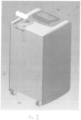
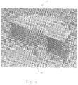
Fig. 1 is an image of a multiple-bore solute cartridge carrier, adapted for single-use with a sterile fluid delivery system, constructed in accordance with one aspect of the present disclosure; -
Fig. 2 is a perspective view showing a sterile fluid delivery system adapted for use with the multiple-bore solute cartridge carrier inFig. 1 ; -
Fig. 3 is a partial detail view showing the sterile fluid delivery system inFig. 2 ; -
Fig. 4 is a perspective cutaway view of the multiple-bore solute cartridge carrier shown inFig. 1 ; -
Fig. 5 is a perspective cutaway view of a single bore comprising the multiple-bore solute cartridge carrier inFig. 1 ; -
Fig. 6 is a perspective cutaway view of a single solute cartridge for use with the multiple-bore solute cartridge carrier inFig. 1 ; and -
Fig. 7 is a perspective view of a solute cartridge carrier constructed in accordance with another aspect of the present disclosure. - Unless defined otherwise, all technical and scientific terms used herein have the same meaning as is commonly understood by one of skill in the art to which the present disclosure pertains.
- In the context of the present disclosure, the singular forms "a," "an" and "the" can include the plural forms as well, unless the context clearly indicates otherwise. It will be further understood that the terms "comprises" and/or "comprising," as used herein, can specify the presence of stated features, steps, operations, elements, and/or components, but do not preclude the presence or addition of one or more other features, steps, operations, elements, components, and/or groups thereof.
- As used herein, the term "and/or" can include any and all combinations of one or more of the associated listed items.
- As used herein, phrases such as "between X and Y" and "between about X and Y" can be interpreted to include X and Y.
- As used herein, phrases such as "between about X and Y" can mean "between about X and about Y."
- As used herein, phrases such as "from about X to Y" can mean "from about X to about Y."
- It will be understood that when an element is referred to as being "on," "attached" to, "connected" to, "coupled" with, "contacting," etc., another element, it can be directly on, attached to, connected to, coupled with or contacting the other element or intervening elements may also be present. In contrast, when an element is referred to as being, for example, "directly on," "directly attached" to, "directly connected" to, "directly coupled" with or "directly contacting" another element, there are no intervening elements present. It will also be appreciated by those of skill in the art that references to a structure or feature that is disposed "adjacent" another feature may have portions that overlap or underlie the adjacent feature.
- Spatially relative terms, such as "under," "below," "lower," "over," "upper" and the like, may be used herein for ease of description to describe one element or feature's relationship to another element(s) or feature(s) as illustrated in the figures. It will be understood that the spatially relative terms can encompass different orientations of the apparatus in use or operation in addition to the orientation depicted in the figures. For example, if the apparatus in the figures is inverted, elements described as "under" or "beneath" other elements or features would then be oriented "over" the other elements or features.
- It will be understood that, although the terms "first," "second," etc. may be used herein to describe various elements, these elements should not be limited by these terms. These terms are only used to distinguish one element from another. Thus, a "first" element discussed below could also be termed a "second" element without departing from the teachings of the present disclosure. The sequence of operations (or steps) is not limited to the order presented in the claims or figures unless specifically indicated otherwise.
- The present disclosure relates to devices and methods for sterile fluid production and, more particularly, to a multiple-bore solute cartridge carrier for use in a sterile fluid delivery system. The multiple-bore solute cartridge carrier 10 (
Fig. 1 ) of the present disclosure, along with a sterile fluid delivery system (Figs. 2-3 ), advantageously provides a stable and convenient way of storing a solute and dispensing a sterile fluid solution. The multiple-bore solute cartridge carrier 10 (Fig. 1 ) can easily and quickly be replaced to replenish the supply of solute, thereby overcoming drawbacks associated with conventional portable fluid delivery systems, such as fluid supply limitations, transportation and storage of fluid bags, etc. Additionally, the ease and quickness with which the multiple-bore solute cartridge carrier 10 can be replaced and/or swapped allows a user to readily change between different desired solutes. - The sterile fluid delivery system 70 provides on-demand delivery of a sterile fluid and/or solution. The sterile fluid delivery system 70 may be configured for a variety of uses such as, medical and/or household applications. The sterile fluid delivery system 70 can comprise a housing 84 configured to enclose components of the sterile fluid delivery system 70 including, but not limited to, a fluid conduit (not shown), a purification and/or sterilization mechanism (not shown), and a controller 86. The housing 84 may be made from a metal, metal alloy, plastic (e.g. polyethylene terephthalate, high density polyethylene, polyvinyl chloride), or a combination thereof. The housing 84 may be provided with a plurality of wheels 88 to assist with transportation of the sterile fluid delivery system 70.
- The fluid conduit may be configured to convey fluid from an external fluid source (not shown) (e.g., a wall outlet port) to the purification and/or sterilization mechanism. One end of the fluid conduit may be adapted to mate with the external fluid source (e.g. a wall outlet port). Alternatively, the sterile fluid delivery system 70 may be free from attachment with an external fluid source and, instead, the fluid conduit may be adapted to mate with an internal fluid source. The internal fluid source (not shown) advantageously allows the sterile fluid delivery system 70 to be moved to any desired location without being constrained to a location near an external fluid source. The purification and/or sterilization mechanism may be, in one example, a filter of the type commercially available from Parker Hannifin Corp. (Cleveland, OH) (e.g. Fluflo Honeycomb Filter Cartridge, Part No. M19R10A-RS).
- The controller 86 may be configured to command one or more operations of the sterile fluid delivery system 70 such as, fluid flow, fluid temperature, solution concentration etc. The controller 86 is in electrical communication with one or more components of the sterile fluid delivery system 70. The controller 86 may include various electrical components (e.g. microprocessor, memory, power source, etc.) The controller 86 may also include various software programs configured to control the sterile fluid delivery system 70. The software programs may comprise, for example, physician-specific or procedure-specific profiles that include personalize-able or pre-set control settings. The controller 86 may be located on a top portion of the housing 84, or at any other suitable location. The controller 86 is in electrical communication with one or more components of the sterile fluid delivery system 70.
- In one example, the sterile fluid delivery system 70 is constructed as disclosed in
U.S. Provisional Patent Application Serial No. 62/132,618, filed March 13, 2015 - One aspect of the present disclosure includes a multiple-bore solute cartridge carrier 10 (
Fig. 1 ) comprising a rotary housing 12 adapted for use with a sterile fluid delivery system 70 (Figs. 2-3 ). The rotary housing 12 can be substantially O-shaped; however, other shapes are possible. The rotary housing 12 may be made of a metal, metal alloy, a plastic (e.g., polyethylene terephthalate, high density polyethylene, polyvinyl chloride), or a combination thereof. - Referring to
Fig. 4 , the rotary housing 12 is defined by an inner wall 20, an outer wall 22, oppositely disposed first and second surfaces 14, 16, and a central axis 18. The first surface 14 of the rotary housing 12 can include one or more rotary transmission elements 50. The rotary transmission elements 50 can be disposed equidistant from one another, and circumferentially about, the central axis 18 of the rotary housing 12. The rotary transmission elements 50 are configured to transmit rotary motion from the sterile fluid delivery system 70 to the cartridge carrier 10 to enable rotation of the cartridge carrier 10 relative to the sterile fluid delivery system 70. - The rotary housing 12 includes bores 30 extending between the first and second surfaces 14, 16. The bores 30 can be equally spaced apart from one another and disposed circumferentially about the central axis 18. In one example, the rotary housing 12 can include six bores 30. Each bore 30 (
Fig. 5 ) extends along a central axis 32 between a filling end 34 and a draining end 36. The central axis 32 of each bore 30 extends substantially parallel to the central axis 18 of the rotary housing 12. Each bore 30 is at least partly defined by a substantially cylindrical inner wall surface 37. The filling end 34 is defined by a substantially circular opening in the first surface 14 of the rotary housing 12. A drain port 38 is located at the draining end 36. The drain port 38 extends coaxially with the central axis 32 through the second surface 16 of the rotary housing 12 so that the drain port 38, an interior volume 40 of the bore 30, and the filling end 34 are in fluid communication with one another. - Each bore 30 is configured to receive a solute cartridge 41 (
Fig. 6 ), which is removable from a respective bore 30. Each solute cartridge 41 is formed separately from a respective bore; however, in some instances, asolute cartridge 42 may be integrally formed with the inner wall surface 37 of a respective bore 30 such that thesolute cartridge 42 is non-removable. Each solute cartridge 41 includes aframe 42 that supports a filter 44. The dimensions of theframe 42 are equal to (or substantially equal to) the interior dimensions of a bore 30. Theframe 42 can be made of a metal, metal alloy, a plastic (e.g., polyethylene terephthalate, high density polyethylene, polyvinyl chloride), or a combination thereof. - The filter 44 is disposed at the bottom of the
frame 42 and is located at the draining end 36 of the bore 30 when the solute cartridge 41 is positioned within the bore. The filter 44 can comprise a wire mesh that includes a plurality of openings, each of which have a diameter between about ten and one hundred microns, such as less than fifty microns (e.g., less than thirty microns). Each solute cartridge 41 is configured to hold or contain asolute 46, such as sodium chloride. Examples of other solutes that may be contained within a solute cartridge 41 can include lactate, dextrose, etc. Additionally, the solute cartridge 41 can be configured to hold or contain a pharmaceutical agent, such as antibiotics,antimicrobial agents, silver ions, etc. - A sealing
material 52 closes and seals the filling end 34 of each bore 30, thereby closing off the interior volume 40 of each bore 30 from the exterior environment. In the configuration illustrated inFig. 1 , a single sheet of sealingmaterial 52 is provided to seal all of the bores 30. The single sheet of sealingmaterial 52 extends across the entire first surface 14 of the rotary housing 12. However, it will be appreciated that each bore 30 may be provided with a separate sheet of sealingmaterial 52. In the configuration ofFig. 1 , for example, six separate sheets of sealingmaterial 52 would be provided so that each individual bore 30 is sealed with a separate one of the six sheets. In some instances, the sealingmaterial 52 is made of a metal foil that can be punctured during operation of the sterile fluid delivery system 70. It is contemplated that any other material(s) can be used to form the sealingmaterial 52. For example, the sealingmaterial 52 can be made of a rubber membrane having a number of self-sealing slits through which certain components of the sterile fluid delivery system 70 can selectively extend. - In one aspect, the multiple-bore solute cartridge carrier 10 can include one or more radio frequency identification (RFID) tags associated with one or more of the solute cartridges 41. The RFID tag(s) can communicate with the controller 86 of the sterile fluid delivery system 70 to indicate the solute contents of each solute cartridge 41. The contents of the solute cartridges 41 can also be determined by having the sterile fluid delivery system 70 sense a physical characteristic of the solute cartridges 41, such as color, weight, and/or size, etc. Additionally, or optionally, the RFID tag(s) can provide information relating to ideal operating parameters (e.g., temperature, flow rate, etc.) of the sterile fluid delivery system 70 to optimize production of the solution.
- In another aspect, a solute cartridge carrier 200 (
Fig. 7 ) can be configured as a substantially cuboid housing 202. The housing 202 can define an interior space configured to receive a plurality ofcartridges 30a-30e of the type shown inFig. 6 . The carrier 200 can have a first end 204, asecond end 206, and an operating section 208 at the first end. The operating section 208 can include a disposal door (not shown). - In use, the cartridges 30 can be loaded into the carrier 200 at the
second end 206. The sterile fluid delivery system 70 can interact with thecartridge 30a positioned in the operation section 208 to produce a desired solution. When the supply of solute in thefirst cartridge 30a is exhausted, the sterile fluid delivery system 70 can open the disposal door to eject the exhausted cartridge from the first end 204 and advance the second cartridge 30b into the operation section 208. - Use of a multiple-bore solute cartridge carrier 10 (
Figs. 2-3 ) in a sterile fluid delivery system 70 to produce a sterile fluid solution will now be described. First, a door 72 provided on the sterile fluid delivery system 70 is opened to reveal acartridge retaining area 74. The door 72 may have locking features that prevent unauthorized access to thecartridge retaining area 74. Thecartridge retaining area 74 can include a fluid nozzle 76, a drain nozzle (not shown), and a rotary transmission member 78 (Fig. 4 ). The cartridge carrier 10 is placed in thecartridge retaining area 74 such that the rotary transmission member 78 engages the rotary transmission receiving depressions 50, thereby rotatably fixing the cartridge carrier 10 to the rotary transmission member 78. Next, the door 72 is closed. - The sterile fluid delivery system 70 includes a drive mechanism (not shown) that rotates the rotary transmission member 78 and causes likewise rotation of the cartridge carrier 10 about the central axis 18 of the rotary housing 12. The cartridge carrier 10 is rotated until the drain nozzle in the
cartridge retaining area 74 is aligned with the drain port 38 of afirst bore 30a. Aligning the drain nozzle with the drain port 38 also substantially aligns the fluid nozzle 76 with the central axis 32 of thefirst bore 30a. The system 70 then drives the fluid nozzle 76 to pierce the sealingmaterial 52 covering the filling end 34 of thefirst bore 30a. The fluid nozzle 76 is thereby positioned in the interior volume 40 of thefirst bore 30a so that the fluid nozzle is in fluid communication with the solute cartridge 48. As the fluid nozzle 76 pierces the sealingmaterial 52, the drain nozzle is simultaneously moved into fluid communication with the drain port 38. - Next, the sterile fluid delivery system supplies 70 sterile fluid (e.g. water) to the fluid nozzle 76. The sterile fluid delivery system 70 may modulate certain properties of the sterile fluid before it is supplied to the fluid nozzle 76, such as temperature, conductivity, pathogen count, etc. The sterile fluid flows from the fluid nozzle 76 into the solute cartridge 41 to dissolve the solute 46 (e.g., sodium chloride) to create a sterile sodium chloride solution. The sterile sodium chloride solution passes through the filter 44 and out of the
bore 30a via the drain port 38. The sterile sodium chloride solution flows from the drain port 38 and is received by the drain nozzle. The drain nozzle is fluidly coupled to additional components of the sterile fluid delivery system 70, which enable on-demand delivery of the sterile sodium chloride solution. - Eventually, the supply of sodium chloride in the solute cartridge 41 will be exhausted, at which point it is necessary to index the cartridge carrier 10 from the
first bore 30a to a second bore 30b if additional sterile sodium chloride solution is desired. The level of sodium chloride contained within each solute cartridge 48 may be ascertained, for example, by monitoring the resulting sterile sodium chloride solution to determine when the solution concentration drops below a desired concentration. Alternatively, the sterile fluid delivery system 70 may be provided with information relating to the amount of solution that can be produced by each solute cartridge 48. For example, the sterile fluid delivery system 70 may be programmed to recognize that the supply ofsodium chloride solute 46 in one solute cartridge 41 will be exhausted once a certain volume of sterile sodium chloride solution has been created. - When it is desirable to index the cartridge carrier 10 from the
first bore 30a to the second bore 30b, the sterile fluid delivery system 70 ensures that the supply of sterile water to the fluid nozzle 76 is stopped. For example, the cartridge carrier 10 can include a detection mechanism (not shown) for communicating with the controller 86 to signal the indexed position of the cartridge carrier. Additionally, or alternatively, the detection mechanism can signal when the cartridge carrier 10 needs to be replaced. - Next, the sterile fluid delivery system 70 simultaneously withdraws the fluid nozzle 76 from the interior volume 40 of the fist bore 30a and the drain nozzle out of fluid engagement with the drain port 38. The sterile fluid delivery system 70 then actuates the rotary transmission member 78 to rotate the cartridge carrier 10 until the central axis 32 of the second bore 30b is in alignment with the fluid nozzle 76. At this point, the above-described process can be repeated to prepare additional sterile fluid solution (e.g., sterile sodium chloride solution).
- From the above description of the present disclosure, those skilled in the art will perceive improvements, changes and modifications. For example, the sterile fluid delivery system 70 can be configured to hold the multiple-bore solute cartridge carrier 10 stationary and move the drain nozzle and drain port 38 relative to the multiple-bore solute cartridge carrier 10 to index between the bores 30. As a further example, the sterile fluid delivery system 70 can include a plurality of drain nozzles and drain ports 38 that are configured to simultaneously engage a plurality of the bores 30 to allow for the concurrent production of different solutions that can be combined in the sterile fluid delivery system 70 and delivered on-demand to a desired site.
Claims (10)
- A multiple-bore solute cartridge carrier (10) for use in a sterile fluid delivery system (70), the carrier (10) comprising:a rotary housing (12) adapted for connection to the sterile fluid delivery system (70), the rotary housing (12) being defined by an inner wall (20), an outer wall (22), oppositely disposed first and second surfaces (14, 16), and a central axis (18), the rotary housing (12) including multiple bores (30) extending between the first and second surfaces (14, 16);wherein each bore (30) extends along a central axis (32) between a filling end (34) and a draining end (36) with the central axis (32) of each bore (30) extending substantially parallel to the central axis (18) of the rotary housing (12),wherein each bore (30) is at least partly defined by a substantially cylindrical inner wall surface (37), the filling end (34) is defined by a circular opening in the first surface (14), and a drain port (38) is located at the draining end (36) with the drain port (38) extending coaxially with the central axis (32) of the bore (30) through the second surface (16) of the rotary housing (12) so that the drain port (38), an interior volume (40) of the bore (30), and the filling end (34) are in fluid communication with one another; andmultiple solute cartridges (41), each solute cartridge (41) being in a corresponding bore (30), each solute cartridge (41) including a frame (42) having dimensions equal to the interior dimensions of a corresponding bore (30); a filter (44) supported by the frame (42), and a solute (46) contained therein;
wherein each filter (44) is disposed at the bottom of the respective frame (42) and is located at the draining end (36) of a corresponding bore (30) when the solute cartridge (41) is positioned within the bore;wherein the sterile fluid delivery system (70) is configured to flow water through the solute cartridges (41) to create a desired sterile solution. - The multiple-bore solute cartridge carrier (10) according to claim 1, wherein the rotary housing (12), when connected to the sterile fluid delivery system (70), is selectively rotatable to facilitate creation of the desired sterile solution.
- The multiple-bore solute cartridge carrier (10) according to claim 1, wherein the solute (46) is a pharmaceutical agent.
- The multiple-bore solute cartridge carrier (10) according to claim 3, wherein the pharmaceutical agent is at least one of an antibiotic, an antimicrobial agent, and silver ions.
- The multiple-bore solute cartridge carrier (10) according to claim 3, wherein the solute (46) is one of sodium chloride, lactate, and dextrose.
- The multiple-bore solute cartridge carrier (10) according to claim 1, wherein the frame (42) of each of the solute cartridges (41) is integrally formed with the inner wall surface (37) defining a respective bore (30).
- The multiple-bore solute cartridge carrier(10) according to claim 1, wherein each of the solute cartridges (41) is formed separately, and is removable from, a respective one of the bores (30).
- The multiple-bore solute cartridge carrier (10) according to claim 1, wherein an end of each solute cartridge (41) is sealed by a sealing material.
- The multiple-bore solute cartridge carrier (10) according to claim 1, wherein prior to being received in the sterile fluid delivery system (70) the entire rotary housing (12) is covered by a sealing material (52) so that the multiple-bore solute cartridge carrier (10) is adapted for single-use operation with the sterile fluid delivery system (70), the sealing material closing (52) and sealing the filling ends (34) of the bores (30) thereby closing off interior volumes (40) of the bores (30) from an exterior environment.
- The multiple-bore solute cartridge carrier (10) according to claim 1, wherein the filter (44) of each solute cartridge (41) is designed to filter solids between ten and one hundred microns.
Applications Claiming Priority (3)
| Application Number | Priority Date | Filing Date | Title |
|---|---|---|---|
| US201562132618P | 2015-03-13 | 2015-03-13 | |
| US201562132589P | 2015-03-13 | 2015-03-13 | |
| PCT/US2016/022279 WO2016149177A1 (en) | 2015-03-13 | 2016-03-14 | Multiple-bore solute cartridge carrier |
Publications (2)
| Publication Number | Publication Date |
|---|---|
| EP3268053A1 EP3268053A1 (en) | 2018-01-17 |
| EP3268053B1 true EP3268053B1 (en) | 2023-03-29 |
Family
ID=55640897
Family Applications (2)
| Application Number | Title | Priority Date | Filing Date |
|---|---|---|---|
| EP16712609.3A Active EP3268053B1 (en) | 2015-03-13 | 2016-03-14 | Multiple-bore solute cartridge carrier |
| EP16712611.9A Active EP3268054B1 (en) | 2015-03-13 | 2016-03-14 | Sterile and/or purified fluid and/or solution delivery system |
Family Applications After (1)
| Application Number | Title | Priority Date | Filing Date |
|---|---|---|---|
| EP16712611.9A Active EP3268054B1 (en) | 2015-03-13 | 2016-03-14 | Sterile and/or purified fluid and/or solution delivery system |
Country Status (5)
| Country | Link |
|---|---|
| US (4) | US11097965B2 (en) |
| EP (2) | EP3268053B1 (en) |
| JP (2) | JP2018513778A (en) |
| KR (2) | KR20180036644A (en) |
| WO (2) | WO2016149177A1 (en) |
Families Citing this family (6)
| Publication number | Priority date | Publication date | Assignee | Title |
|---|---|---|---|---|
| US11365134B2 (en) | 2019-07-31 | 2022-06-21 | Access Business Group International Llc | Water treatment system |
| CN110680940B (en) * | 2019-10-15 | 2021-02-02 | 邵阳学院 | Medical dissection apparatus disinfecting equipment |
| EP4065472A1 (en) | 2019-11-25 | 2022-10-05 | DEKA Products Limited Partnership | System for producing and packaging fluid, sealing member dispenser, reservoir feeding apparatus, bag sealing apparatus, reservoir filling set, method for filling a reservoir or a bag, filling and sampling nozzle |
| EP4600175A3 (en) | 2020-11-25 | 2025-12-31 | DEKA Products Limited Partnership | SYSTEMS, METHOD AND APPARATUS FOR THE MANUFACTURING AND PACKAGING OF LIQUIDS |
| US20220168165A1 (en) * | 2020-11-30 | 2022-06-02 | Heather Farrell | Wheeled Apparatus For Transporting A Portable Oxygen Concentrator Or Other Medical Device |
| JP2022110507A (en) * | 2021-01-18 | 2022-07-29 | 三菱ケミカルアクア・ソリューションズ株式会社 | Underground water purification device |
Citations (1)
| Publication number | Priority date | Publication date | Assignee | Title |
|---|---|---|---|---|
| US20060204405A1 (en) * | 2003-04-07 | 2006-09-14 | Ragnar Tryggvason | Device for use in a cartridge, and a cartridge |
Family Cites Families (49)
| Publication number | Priority date | Publication date | Assignee | Title |
|---|---|---|---|---|
| JPS5242787B1 (en) | 1970-12-29 | 1977-10-26 | ||
| US3876234A (en) | 1973-01-11 | 1975-04-08 | Extracorporeal Med Spec | Twist-lock connector |
| US4022205A (en) | 1973-11-05 | 1977-05-10 | Tenczar Francis J | Fluid connectors |
| US4495067A (en) | 1980-12-02 | 1985-01-22 | Tracor, Inc. | Apparatus for preparation of infusion grade water |
| JPS6040567Y2 (en) | 1982-11-19 | 1985-12-07 | 株式会社島津製作所 | Reagent solution preparation device |
| US5032265A (en) | 1990-06-20 | 1991-07-16 | Millipore Corporation | Method and system for producing sterile aqueous solutions |
| US5259954A (en) | 1991-12-16 | 1993-11-09 | Sepratech, Inc. | Portable intravenous solution preparation apparatus and method |
| US6030359A (en) | 1996-12-11 | 2000-02-29 | Northgate Technologies Inc | Apparatus and method for delivering fluid flow to a surgical site |
| US5925240A (en) * | 1997-05-20 | 1999-07-20 | United States Filter Corporation | Water treatment system having dosing control |
| US5919357A (en) | 1997-05-20 | 1999-07-06 | United States Filter Corporation | Filter cartridge assembly |
| US6139571A (en) | 1997-07-09 | 2000-10-31 | Fuller Research Corporation | Heated fluid surgical instrument |
| US6080313A (en) | 1997-08-29 | 2000-06-27 | Kelada; Maher I. | Point-of-use water purification system with a cascade ion exchange option |
| IL121885A0 (en) * | 1997-10-05 | 1998-03-10 | Soda Club Holdings Nv | Water purifying and dispensing apparatus |
| US6043097A (en) * | 1997-12-05 | 2000-03-28 | Bayer Corporation | Reagent package |
| ATE202711T1 (en) * | 1997-12-23 | 2001-07-15 | Steris Corp | ARRANGEMENT FOR RELEASING AN ANTIMICROBIAL COMPOSITION WITH INTEGRATED FILTER |
| WO2000051705A1 (en) | 1999-03-03 | 2000-09-08 | Prismedical Corporation | Methods and devices for preparing hemodialysis solutions |
| JP2000348249A (en) * | 1999-06-09 | 2000-12-15 | Fuji Enterprise:Kk | Ultraviolet-ray sterilization system for automatic vending machine |
| WO2001011374A2 (en) * | 1999-08-06 | 2001-02-15 | Thermo Biostar, Inc. | An automated point of care detection system including complete sample processing capabilities |
| AU7486100A (en) | 1999-09-14 | 2001-04-17 | James W. Chandler | System and method of controlling microorganism and biofilms |
| US6164314A (en) | 2000-01-12 | 2000-12-26 | Intex Recreation Corp. | Oversized air valve for use with inflatable devices and method |
| DK1399193T3 (en) * | 2001-02-16 | 2014-03-31 | Piedmont Renal Clinics P A | Automated peritoneal dialysis system and method of in-line sterilization of the dialysate |
| CN100351006C (en) | 2001-05-14 | 2007-11-28 | 沃特海尔斯国际公司 | Powered sterile solution device |
| JP2003030740A (en) * | 2001-07-03 | 2003-01-31 | Yuji Fukuda | Automatic vending device for mineral water |
| KR20030008504A (en) | 2001-07-18 | 2003-01-29 | 김희동 | Shower apparatus capable of ejecting detergent and method thereof |
| JP4519930B2 (en) * | 2001-12-11 | 2010-08-04 | 野村マイクロ・サイエンス株式会社 | Ultrapure water production method and ultrapure water production apparatus |
| US6948420B2 (en) | 2003-07-22 | 2005-09-27 | The Coca-Cola Company | Coffee and tea pod |
| US7229599B2 (en) | 2003-08-01 | 2007-06-12 | Steris Inc. | Chemical delivery container |
| US7744817B2 (en) | 2003-08-11 | 2010-06-29 | Sakura Finetek U.S.A., Inc. | Manifold assembly |
| JPWO2005049858A1 (en) * | 2003-11-19 | 2007-11-29 | 第一化学薬品株式会社 | Method for measuring substrate in samples containing hemoglobin |
| US7017953B2 (en) | 2003-12-08 | 2006-03-28 | General Motors Corporation | Twist lock assembly |
| US20050171501A1 (en) | 2004-02-03 | 2005-08-04 | Thomas Kelly | Intravenous solution producing systems and methods |
| US7947010B2 (en) | 2005-07-08 | 2011-05-24 | Depuy Products, Inc. | Composition and system for wound decontamination |
| CN101218007B (en) * | 2005-07-11 | 2011-10-05 | 安格斯公司 | filter module |
| JP2007252396A (en) * | 2006-03-20 | 2007-10-04 | Kitasato Gakuen | Manufacturing device and manufacturing method of medical purpose dialysis fluid |
| WO2007118235A2 (en) | 2006-04-07 | 2007-10-18 | Nxstage Medical Inc. | Filtration system for preparation of fluids for medical applications. |
| FR2902026A1 (en) * | 2006-06-12 | 2007-12-14 | Vladimir Grcevic | MOBILE UNIT FOR THE TREATMENT OF RAW WATER |
| US20080146991A1 (en) | 2006-12-18 | 2008-06-19 | Chris Hernandez | Hand operated dispenser for surgical irrigation fluids |
| JP4990710B2 (en) | 2007-07-25 | 2012-08-01 | 三菱レイヨン株式会社 | Medical purified water production apparatus and hot water disinfection method for nanofiltration membrane |
| NO327658B1 (en) | 2007-10-03 | 2009-09-07 | Fmc Kongsberg Subsea As | Apparatus and method for painting water content and salt concentration in a multiphase fluid stream |
| US20090283409A1 (en) * | 2008-05-14 | 2009-11-19 | Tommy Stern | Under-sink Apparatus for Target Pharmaceutical Compound Treatment |
| JP2010022936A (en) * | 2008-07-18 | 2010-02-04 | Ube Ind Ltd | Apparatus and method for producing ultrapure water |
| EP2447697B1 (en) | 2009-06-25 | 2019-01-30 | Hitachi High-Technologies Corporation | Preprocessing apparatus |
| GB0919477D0 (en) | 2009-11-06 | 2009-12-23 | Otv Sa | Water purification apparatus and method |
| KR101012191B1 (en) | 2010-07-20 | 2011-02-08 | 이문섭 | Kidney dialysis water production apparatus and kidney dialysis water production method |
| GB201012490D0 (en) | 2010-07-26 | 2010-09-08 | Randox Lab Ltd | Sealed well assembly, cartridge thereof, and apparatus and method for opening a sealed well assembly |
| JP5914964B2 (en) * | 2010-10-18 | 2016-05-11 | 栗田工業株式会社 | Ultrapure water production method |
| DK2694445T3 (en) * | 2011-04-04 | 2016-11-14 | Much More Water As | Mobile water purification system |
| DE102012021595A1 (en) | 2012-11-02 | 2014-05-08 | Hydac Process Technology Gmbh | Filter device for fluids |
| WO2015013253A2 (en) * | 2013-07-25 | 2015-01-29 | Siemens Healthcare Diagnostics Inc. | Reagent dispensers, dispensing apparatus, and methods |
-
2016
- 2016-03-14 KR KR1020177025647A patent/KR20180036644A/en not_active Ceased
- 2016-03-14 JP JP2017547454A patent/JP2018513778A/en active Pending
- 2016-03-14 KR KR1020177025646A patent/KR20180036643A/en not_active Abandoned
- 2016-03-14 WO PCT/US2016/022279 patent/WO2016149177A1/en not_active Ceased
- 2016-03-14 US US15/556,126 patent/US11097965B2/en active Active
- 2016-03-14 WO PCT/US2016/022287 patent/WO2016149180A1/en not_active Ceased
- 2016-03-14 EP EP16712609.3A patent/EP3268053B1/en active Active
- 2016-03-14 US US15/555,612 patent/US11021378B2/en active Active
- 2016-03-14 JP JP2017547441A patent/JP2018509287A/en active Pending
- 2016-03-14 EP EP16712611.9A patent/EP3268054B1/en active Active
-
2021
- 2021-02-17 US US17/177,653 patent/US11981588B2/en active Active
-
2024
- 2024-05-03 US US18/654,819 patent/US12365609B2/en active Active
Patent Citations (1)
| Publication number | Priority date | Publication date | Assignee | Title |
|---|---|---|---|---|
| US20060204405A1 (en) * | 2003-04-07 | 2006-09-14 | Ragnar Tryggvason | Device for use in a cartridge, and a cartridge |
Also Published As
| Publication number | Publication date |
|---|---|
| WO2016149177A1 (en) | 2016-09-22 |
| KR20180036643A (en) | 2018-04-09 |
| EP3268054B1 (en) | 2026-02-11 |
| US20180037485A1 (en) | 2018-02-08 |
| US11021378B2 (en) | 2021-06-01 |
| US20180044208A1 (en) | 2018-02-15 |
| US11097965B2 (en) | 2021-08-24 |
| US12365609B2 (en) | 2025-07-22 |
| US20240286938A1 (en) | 2024-08-29 |
| JP2018513778A (en) | 2018-05-31 |
| EP3268054A1 (en) | 2018-01-17 |
| KR20180036644A (en) | 2018-04-09 |
| WO2016149180A1 (en) | 2016-09-22 |
| EP3268053A1 (en) | 2018-01-17 |
| US20210171371A1 (en) | 2021-06-10 |
| JP2018509287A (en) | 2018-04-05 |
| US11981588B2 (en) | 2024-05-14 |
Similar Documents
| Publication | Publication Date | Title |
|---|---|---|
| US11097965B2 (en) | Multiple-bore solute cartridge carrier | |
| US11643269B2 (en) | Container and opening arrangement for beverage production | |
| US12097476B2 (en) | Compounder apparatus | |
| JP6894937B2 (en) | Fluid delivery system with spiked cassette | |
| US11969537B2 (en) | Medical waste fluid collection and disposal system | |
| EP3653132B1 (en) | Container assembly and associated method | |
| US12221364B2 (en) | Systems, methods, and apparatuses for producing and packaging fluids | |
| EP3925591B1 (en) | Rotary valve pump for automatic drug compounder | |
| ES2791026T3 (en) | A container with a frangible sealed access and a vapor-permeable vent hole | |
| US6267564B1 (en) | Medical reservoir bag and system | |
| US8691154B2 (en) | Apparatus for the generation of cleaning and/or sanitizing solutions | |
| EP3325038B1 (en) | Fluid connectors for dialysis | |
| KR20190003839A (en) | Method for treating dialysate, dialysis system, and method for pre-evaluating dialysis patients for treatment with same | |
| CN120897801A (en) | Systems, apparatus, and methods for fluid transfer within automated cell processing systems. | |
| EP3527253B1 (en) | Automated frangible cannula breaker | |
| EP3383348B1 (en) | Disposable cartridge for automatic drug compounder | |
| CN107847653A (en) | Fusion case for dialysis system | |
| CN113597405A (en) | Filling device for filling containers arranged in disposable isolators | |
| JP5114378B2 (en) | Automatic culture equipment, sealed containers, slide valves and disposable containers | |
| WO2024059039A1 (en) | Cartridge for dispensing medical material | |
| HK40030558A (en) | Container assembly and associated method | |
| WO2021069223A1 (en) | Fluid container device comprising a septum member, and method of delivering fluid from such a device | |
| JP2021514264A (en) | Vehicles for providing dialysate | |
| HK1230117A1 (en) | Method for treating dialysate, dialysis system, and method for pre-evaluating dialysis patients for treatment with same | |
| JP2014100317A (en) | Drug cartridge |
Legal Events
| Date | Code | Title | Description |
|---|---|---|---|
| STAA | Information on the status of an ep patent application or granted ep patent |
Free format text: STATUS: THE INTERNATIONAL PUBLICATION HAS BEEN MADE |
|
| PUAI | Public reference made under article 153(3) epc to a published international application that has entered the european phase |
Free format text: ORIGINAL CODE: 0009012 |
|
| STAA | Information on the status of an ep patent application or granted ep patent |
Free format text: STATUS: REQUEST FOR EXAMINATION WAS MADE |
|
| 17P | Request for examination filed |
Effective date: 20170919 |
|
| AK | Designated contracting states |
Kind code of ref document: A1 Designated state(s): AL AT BE BG CH CY CZ DE DK EE ES FI FR GB GR HR HU IE IS IT LI LT LU LV MC MK MT NL NO PL PT RO RS SE SI SK SM TR |
|
| AX | Request for extension of the european patent |
Extension state: BA ME |
|
| DAV | Request for validation of the european patent (deleted) | ||
| DAX | Request for extension of the european patent (deleted) | ||
| STAA | Information on the status of an ep patent application or granted ep patent |
Free format text: STATUS: EXAMINATION IS IN PROGRESS |
|
| 17Q | First examination report despatched |
Effective date: 20210311 |
|
| GRAP | Despatch of communication of intention to grant a patent |
Free format text: ORIGINAL CODE: EPIDOSNIGR1 |
|
| STAA | Information on the status of an ep patent application or granted ep patent |
Free format text: STATUS: GRANT OF PATENT IS INTENDED |
|
| INTG | Intention to grant announced |
Effective date: 20221018 |
|
| GRAS | Grant fee paid |
Free format text: ORIGINAL CODE: EPIDOSNIGR3 |
|
| GRAA | (expected) grant |
Free format text: ORIGINAL CODE: 0009210 |
|
| STAA | Information on the status of an ep patent application or granted ep patent |
Free format text: STATUS: THE PATENT HAS BEEN GRANTED |
|
| AK | Designated contracting states |
Kind code of ref document: B1 Designated state(s): AL AT BE BG CH CY CZ DE DK EE ES FI FR GB GR HR HU IE IS IT LI LT LU LV MC MK MT NL NO PL PT RO RS SE SI SK SM TR |
|
| REG | Reference to a national code |
Ref country code: GB Ref legal event code: FG4D |
|
| REG | Reference to a national code |
Ref country code: CH Ref legal event code: EP |
|
| REG | Reference to a national code |
Ref country code: DE Ref legal event code: R096 Ref document number: 602016078518 Country of ref document: DE |
|
| REG | Reference to a national code |
Ref country code: AT Ref legal event code: REF Ref document number: 1556220 Country of ref document: AT Kind code of ref document: T Effective date: 20230415 |
|
| REG | Reference to a national code |
Ref country code: IE Ref legal event code: FG4D |
|
| REG | Reference to a national code |
Ref country code: LT Ref legal event code: MG9D |
|
| PG25 | Lapsed in a contracting state [announced via postgrant information from national office to epo] |
Ref country code: RS Free format text: LAPSE BECAUSE OF FAILURE TO SUBMIT A TRANSLATION OF THE DESCRIPTION OR TO PAY THE FEE WITHIN THE PRESCRIBED TIME-LIMIT Effective date: 20230329 Ref country code: NO Free format text: LAPSE BECAUSE OF FAILURE TO SUBMIT A TRANSLATION OF THE DESCRIPTION OR TO PAY THE FEE WITHIN THE PRESCRIBED TIME-LIMIT Effective date: 20230629 Ref country code: LV Free format text: LAPSE BECAUSE OF FAILURE TO SUBMIT A TRANSLATION OF THE DESCRIPTION OR TO PAY THE FEE WITHIN THE PRESCRIBED TIME-LIMIT Effective date: 20230329 Ref country code: LT Free format text: LAPSE BECAUSE OF FAILURE TO SUBMIT A TRANSLATION OF THE DESCRIPTION OR TO PAY THE FEE WITHIN THE PRESCRIBED TIME-LIMIT Effective date: 20230329 Ref country code: HR Free format text: LAPSE BECAUSE OF FAILURE TO SUBMIT A TRANSLATION OF THE DESCRIPTION OR TO PAY THE FEE WITHIN THE PRESCRIBED TIME-LIMIT Effective date: 20230329 |
|
| REG | Reference to a national code |
Ref country code: NL Ref legal event code: MP Effective date: 20230329 |
|
| REG | Reference to a national code |
Ref country code: AT Ref legal event code: MK05 Ref document number: 1556220 Country of ref document: AT Kind code of ref document: T Effective date: 20230329 |
|
| PG25 | Lapsed in a contracting state [announced via postgrant information from national office to epo] |
Ref country code: SE Free format text: LAPSE BECAUSE OF FAILURE TO SUBMIT A TRANSLATION OF THE DESCRIPTION OR TO PAY THE FEE WITHIN THE PRESCRIBED TIME-LIMIT Effective date: 20230329 Ref country code: NL Free format text: LAPSE BECAUSE OF FAILURE TO SUBMIT A TRANSLATION OF THE DESCRIPTION OR TO PAY THE FEE WITHIN THE PRESCRIBED TIME-LIMIT Effective date: 20230329 Ref country code: GR Free format text: LAPSE BECAUSE OF FAILURE TO SUBMIT A TRANSLATION OF THE DESCRIPTION OR TO PAY THE FEE WITHIN THE PRESCRIBED TIME-LIMIT Effective date: 20230630 Ref country code: FI Free format text: LAPSE BECAUSE OF FAILURE TO SUBMIT A TRANSLATION OF THE DESCRIPTION OR TO PAY THE FEE WITHIN THE PRESCRIBED TIME-LIMIT Effective date: 20230329 |
|
| PG25 | Lapsed in a contracting state [announced via postgrant information from national office to epo] |
Ref country code: SM Free format text: LAPSE BECAUSE OF FAILURE TO SUBMIT A TRANSLATION OF THE DESCRIPTION OR TO PAY THE FEE WITHIN THE PRESCRIBED TIME-LIMIT Effective date: 20230329 Ref country code: RO Free format text: LAPSE BECAUSE OF FAILURE TO SUBMIT A TRANSLATION OF THE DESCRIPTION OR TO PAY THE FEE WITHIN THE PRESCRIBED TIME-LIMIT Effective date: 20230329 Ref country code: PT Free format text: LAPSE BECAUSE OF FAILURE TO SUBMIT A TRANSLATION OF THE DESCRIPTION OR TO PAY THE FEE WITHIN THE PRESCRIBED TIME-LIMIT Effective date: 20230731 Ref country code: ES Free format text: LAPSE BECAUSE OF FAILURE TO SUBMIT A TRANSLATION OF THE DESCRIPTION OR TO PAY THE FEE WITHIN THE PRESCRIBED TIME-LIMIT Effective date: 20230329 Ref country code: EE Free format text: LAPSE BECAUSE OF FAILURE TO SUBMIT A TRANSLATION OF THE DESCRIPTION OR TO PAY THE FEE WITHIN THE PRESCRIBED TIME-LIMIT Effective date: 20230329 Ref country code: AT Free format text: LAPSE BECAUSE OF FAILURE TO SUBMIT A TRANSLATION OF THE DESCRIPTION OR TO PAY THE FEE WITHIN THE PRESCRIBED TIME-LIMIT Effective date: 20230329 |
|
| PG25 | Lapsed in a contracting state [announced via postgrant information from national office to epo] |
Ref country code: SK Free format text: LAPSE BECAUSE OF FAILURE TO SUBMIT A TRANSLATION OF THE DESCRIPTION OR TO PAY THE FEE WITHIN THE PRESCRIBED TIME-LIMIT Effective date: 20230329 Ref country code: PL Free format text: LAPSE BECAUSE OF FAILURE TO SUBMIT A TRANSLATION OF THE DESCRIPTION OR TO PAY THE FEE WITHIN THE PRESCRIBED TIME-LIMIT Effective date: 20230329 Ref country code: IS Free format text: LAPSE BECAUSE OF FAILURE TO SUBMIT A TRANSLATION OF THE DESCRIPTION OR TO PAY THE FEE WITHIN THE PRESCRIBED TIME-LIMIT Effective date: 20230729 |
|
| REG | Reference to a national code |
Ref country code: DE Ref legal event code: R097 Ref document number: 602016078518 Country of ref document: DE |
|
| PG25 | Lapsed in a contracting state [announced via postgrant information from national office to epo] |
Ref country code: DK Free format text: LAPSE BECAUSE OF FAILURE TO SUBMIT A TRANSLATION OF THE DESCRIPTION OR TO PAY THE FEE WITHIN THE PRESCRIBED TIME-LIMIT Effective date: 20230329 Ref country code: CZ Free format text: LAPSE BECAUSE OF FAILURE TO SUBMIT A TRANSLATION OF THE DESCRIPTION OR TO PAY THE FEE WITHIN THE PRESCRIBED TIME-LIMIT Effective date: 20230329 |
|
| PLBE | No opposition filed within time limit |
Free format text: ORIGINAL CODE: 0009261 |
|
| STAA | Information on the status of an ep patent application or granted ep patent |
Free format text: STATUS: NO OPPOSITION FILED WITHIN TIME LIMIT |
|
| 26N | No opposition filed |
Effective date: 20240103 |
|
| PG25 | Lapsed in a contracting state [announced via postgrant information from national office to epo] |
Ref country code: SI Free format text: LAPSE BECAUSE OF FAILURE TO SUBMIT A TRANSLATION OF THE DESCRIPTION OR TO PAY THE FEE WITHIN THE PRESCRIBED TIME-LIMIT Effective date: 20230329 |
|
| PG25 | Lapsed in a contracting state [announced via postgrant information from national office to epo] |
Ref country code: SI Free format text: LAPSE BECAUSE OF FAILURE TO SUBMIT A TRANSLATION OF THE DESCRIPTION OR TO PAY THE FEE WITHIN THE PRESCRIBED TIME-LIMIT Effective date: 20230329 Ref country code: IT Free format text: LAPSE BECAUSE OF FAILURE TO SUBMIT A TRANSLATION OF THE DESCRIPTION OR TO PAY THE FEE WITHIN THE PRESCRIBED TIME-LIMIT Effective date: 20230329 |
|
| REG | Reference to a national code |
Ref country code: CH Ref legal event code: PL |
|
| PG25 | Lapsed in a contracting state [announced via postgrant information from national office to epo] |
Ref country code: BG Free format text: LAPSE BECAUSE OF FAILURE TO SUBMIT A TRANSLATION OF THE DESCRIPTION OR TO PAY THE FEE WITHIN THE PRESCRIBED TIME-LIMIT Effective date: 20230329 |
|
| PG25 | Lapsed in a contracting state [announced via postgrant information from national office to epo] |
Ref country code: LU Free format text: LAPSE BECAUSE OF NON-PAYMENT OF DUE FEES Effective date: 20240314 |
|
| PG25 | Lapsed in a contracting state [announced via postgrant information from national office to epo] |
Ref country code: MC Free format text: LAPSE BECAUSE OF FAILURE TO SUBMIT A TRANSLATION OF THE DESCRIPTION OR TO PAY THE FEE WITHIN THE PRESCRIBED TIME-LIMIT Effective date: 20230329 |
|
| PG25 | Lapsed in a contracting state [announced via postgrant information from national office to epo] |
Ref country code: MC Free format text: LAPSE BECAUSE OF FAILURE TO SUBMIT A TRANSLATION OF THE DESCRIPTION OR TO PAY THE FEE WITHIN THE PRESCRIBED TIME-LIMIT Effective date: 20230329 Ref country code: LU Free format text: LAPSE BECAUSE OF NON-PAYMENT OF DUE FEES Effective date: 20240314 Ref country code: BG Free format text: LAPSE BECAUSE OF FAILURE TO SUBMIT A TRANSLATION OF THE DESCRIPTION OR TO PAY THE FEE WITHIN THE PRESCRIBED TIME-LIMIT Effective date: 20230329 |
|
| REG | Reference to a national code |
Ref country code: BE Ref legal event code: MM Effective date: 20240331 |
|
| PG25 | Lapsed in a contracting state [announced via postgrant information from national office to epo] |
Ref country code: BE Free format text: LAPSE BECAUSE OF NON-PAYMENT OF DUE FEES Effective date: 20240331 |
|
| PG25 | Lapsed in a contracting state [announced via postgrant information from national office to epo] |
Ref country code: IE Free format text: LAPSE BECAUSE OF NON-PAYMENT OF DUE FEES Effective date: 20240314 |
|
| PG25 | Lapsed in a contracting state [announced via postgrant information from national office to epo] |
Ref country code: IE Free format text: LAPSE BECAUSE OF NON-PAYMENT OF DUE FEES Effective date: 20240314 Ref country code: BE Free format text: LAPSE BECAUSE OF NON-PAYMENT OF DUE FEES Effective date: 20240331 Ref country code: CH Free format text: LAPSE BECAUSE OF NON-PAYMENT OF DUE FEES Effective date: 20240331 |
|
| PG25 | Lapsed in a contracting state [announced via postgrant information from national office to epo] |
Ref country code: CY Free format text: LAPSE BECAUSE OF FAILURE TO SUBMIT A TRANSLATION OF THE DESCRIPTION OR TO PAY THE FEE WITHIN THE PRESCRIBED TIME-LIMIT; INVALID AB INITIO Effective date: 20160314 |
|
| PG25 | Lapsed in a contracting state [announced via postgrant information from national office to epo] |
Ref country code: HU Free format text: LAPSE BECAUSE OF FAILURE TO SUBMIT A TRANSLATION OF THE DESCRIPTION OR TO PAY THE FEE WITHIN THE PRESCRIBED TIME-LIMIT; INVALID AB INITIO Effective date: 20160314 |
|
| PG25 | Lapsed in a contracting state [announced via postgrant information from national office to epo] |
Ref country code: TR Free format text: LAPSE BECAUSE OF FAILURE TO SUBMIT A TRANSLATION OF THE DESCRIPTION OR TO PAY THE FEE WITHIN THE PRESCRIBED TIME-LIMIT Effective date: 20230329 |
|
| PGFP | Annual fee paid to national office [announced via postgrant information from national office to epo] |
Ref country code: GB Payment date: 20260325 Year of fee payment: 11 |
|
| PGFP | Annual fee paid to national office [announced via postgrant information from national office to epo] |
Ref country code: DE Payment date: 20260320 Year of fee payment: 11 |
|
| PGFP | Annual fee paid to national office [announced via postgrant information from national office to epo] |
Ref country code: FR Payment date: 20260324 Year of fee payment: 11 |