EP3267743A2 - Uplink power sharing control - Google Patents
Uplink power sharing control Download PDFInfo
- Publication number
- EP3267743A2 EP3267743A2 EP17189269.8A EP17189269A EP3267743A2 EP 3267743 A2 EP3267743 A2 EP 3267743A2 EP 17189269 A EP17189269 A EP 17189269A EP 3267743 A2 EP3267743 A2 EP 3267743A2
- Authority
- EP
- European Patent Office
- Prior art keywords
- uplink
- transmission
- access network
- wireless access
- transmissions
- Prior art date
- Legal status (The legal status is an assumption and is not a legal conclusion. Google has not performed a legal analysis and makes no representation as to the accuracy of the status listed.)
- Granted
Links
- 230000005540 biological transmission Effects 0.000 claims abstract description 296
- 230000004044 response Effects 0.000 claims abstract description 11
- 238000000034 method Methods 0.000 claims description 58
- 239000000969 carrier Substances 0.000 claims description 35
- 238000012913 prioritisation Methods 0.000 claims description 31
- 238000004891 communication Methods 0.000 claims description 27
- 230000002776 aggregation Effects 0.000 claims description 21
- 238000004220 aggregation Methods 0.000 claims description 21
- 230000008054 signal transmission Effects 0.000 claims description 15
- 101100465000 Mus musculus Prag1 gene Proteins 0.000 description 33
- 230000011664 signaling Effects 0.000 description 10
- 238000003860 storage Methods 0.000 description 9
- 238000005259 measurement Methods 0.000 description 8
- 230000006870 function Effects 0.000 description 7
- 238000004364 calculation method Methods 0.000 description 6
- 230000008569 process Effects 0.000 description 6
- 230000015654 memory Effects 0.000 description 5
- 230000000737 periodic effect Effects 0.000 description 5
- 238000010586 diagram Methods 0.000 description 4
- 230000001360 synchronised effect Effects 0.000 description 4
- 238000001514 detection method Methods 0.000 description 3
- 238000007726 management method Methods 0.000 description 3
- 230000007246 mechanism Effects 0.000 description 3
- 238000010295 mobile communication Methods 0.000 description 3
- 230000009471 action Effects 0.000 description 2
- 230000001934 delay Effects 0.000 description 2
- 230000001419 dependent effect Effects 0.000 description 2
- 230000009977 dual effect Effects 0.000 description 2
- 230000007774 longterm Effects 0.000 description 2
- 238000004519 manufacturing process Methods 0.000 description 2
- 230000004048 modification Effects 0.000 description 2
- 238000012986 modification Methods 0.000 description 2
- 101000741965 Homo sapiens Inactive tyrosine-protein kinase PRAG1 Proteins 0.000 description 1
- 102100038659 Inactive tyrosine-protein kinase PRAG1 Human genes 0.000 description 1
- 230000004913 activation Effects 0.000 description 1
- 230000006399 behavior Effects 0.000 description 1
- 230000000295 complement effect Effects 0.000 description 1
- 230000009849 deactivation Effects 0.000 description 1
- 238000005516 engineering process Methods 0.000 description 1
- 238000009472 formulation Methods 0.000 description 1
- 239000011159 matrix material Substances 0.000 description 1
- 239000000203 mixture Substances 0.000 description 1
- 230000003287 optical effect Effects 0.000 description 1
- 238000011084 recovery Methods 0.000 description 1
- 230000009467 reduction Effects 0.000 description 1
- 239000004065 semiconductor Substances 0.000 description 1
- 238000004904 shortening Methods 0.000 description 1
- 230000003068 static effect Effects 0.000 description 1
- 230000001960 triggered effect Effects 0.000 description 1
Images


Classifications
-
- H—ELECTRICITY
- H04—ELECTRIC COMMUNICATION TECHNIQUE
- H04W—WIRELESS COMMUNICATION NETWORKS
- H04W52/00—Power management, e.g. TPC [Transmission Power Control], power saving or power classes
- H04W52/04—TPC
- H04W52/18—TPC being performed according to specific parameters
- H04W52/28—TPC being performed according to specific parameters using user profile, e.g. mobile speed, priority or network state, e.g. standby, idle or non transmission
- H04W52/281—TPC being performed according to specific parameters using user profile, e.g. mobile speed, priority or network state, e.g. standby, idle or non transmission taking into account user or data type priority
-
- H—ELECTRICITY
- H04—ELECTRIC COMMUNICATION TECHNIQUE
- H04W—WIRELESS COMMUNICATION NETWORKS
- H04W52/00—Power management, e.g. TPC [Transmission Power Control], power saving or power classes
- H04W52/04—TPC
- H04W52/30—TPC using constraints in the total amount of available transmission power
- H04W52/36—TPC using constraints in the total amount of available transmission power with a discrete range or set of values, e.g. step size, ramping or offsets
- H04W52/367—Power values between minimum and maximum limits, e.g. dynamic range
-
- H—ELECTRICITY
- H04—ELECTRIC COMMUNICATION TECHNIQUE
- H04W—WIRELESS COMMUNICATION NETWORKS
- H04W72/00—Local resource management
- H04W72/20—Control channels or signalling for resource management
- H04W72/21—Control channels or signalling for resource management in the uplink direction of a wireless link, i.e. towards the network
-
- H—ELECTRICITY
- H04—ELECTRIC COMMUNICATION TECHNIQUE
- H04W—WIRELESS COMMUNICATION NETWORKS
- H04W52/00—Power management, e.g. TPC [Transmission Power Control], power saving or power classes
- H04W52/04—TPC
- H04W52/06—TPC algorithms
- H04W52/14—Separate analysis of uplink or downlink
- H04W52/146—Uplink power control
-
- H—ELECTRICITY
- H04—ELECTRIC COMMUNICATION TECHNIQUE
- H04W—WIRELESS COMMUNICATION NETWORKS
- H04W52/00—Power management, e.g. TPC [Transmission Power Control], power saving or power classes
- H04W52/04—TPC
- H04W52/38—TPC being performed in particular situations
Definitions
- a small cell (or multiple small cells) can operate within a coverage area of a larger cell, referred to as a macro cell.
- a small cell has a coverage area that is smaller than the coverage area of the macro cell.
- a method of a user equipment comprise detecting that an aggregate of calculated uplink transmit power of the UE exceeds a threshold, and in response to the detecting, adjusting a power of at least one of a plurality of frequency-division multiplexing (FDM)-based uplink transmissions of the UE over corresponding wireless connections with respective wireless access network nodes.
- FDM frequency-division multiplexing
- a wireless access network node comprises a communication component to communicate wirelessly with a UE, and at least one processor configured to use information relating to uplink power sharing control at the UE to process an uplink transmission from the UE, where the uplink transmission is one of a plurality of frequency-division multiplexing (FDM)-based uplink transmissions over corresponding wireless connections with respective wireless access network nodes.
- FDM frequency-division multiplexing
- a UE includes a communication component to communicate wirelessly with a wireless access network node, and at least one processor configured to detect that an aggregate of calculated uplink transmit power of the UE exceeds a threshold, and in response to the detecting, adjust a power of at least one of a plurality of frequency-division multiplexing (FDM)-based uplink transmissions of the UE over corresponding wireless connections with respective wireless access network nodes.
- FDM frequency-division multiplexing
- Fig. 1 illustrates an example arrangement that includes network nodes that are part of a mobile communications network that supports wireless communications with user equipments (UEs).
- a node can refer to an electronic device that is capable of sending, receiving, and forwarding information over a communication channel, and of performing designated tasks.
- a macro cell 102 corresponds to a coverage area provided by a macro wireless access network node 104.
- a coverage area can refer to a region where mobile services can be provided by a network node to a target level.
- a wireless access network node is responsible for performing wireless transmissions and receptions with UEs.
- a number of small cells 106 are depicted as being within the coverage area of the macro cell 102. Each small cell 106 corresponds to a coverage area provided by a respective small cell wireless access network node 108.
- One of the small cells is labeled 106-1, and the corresponding small cell wireless access network node is labeled 108-1.
- a small cell can refer to a cell whose coverage area is smaller than the coverage area provided by a larger cell, which is also referred to as a macro cell.
- the frequency at which the macro wireless access network node 104 operates can be lower than that of a small cell wireless access network node 108.
- a lower frequency allows a greater geographic reach for wireless signals transmitted by the macro wireless access network node 104.
- wireless signals transmitted by the small cell wireless access nodes 108 propagate smaller distances.
- small cells 106 can be deployed in relatively close proximity to each other.
- the macro cell 102 can use a frequency that is different from one or more frequencies of the small cells 106. At least some of the small cells 106 can use different frequencies.
- a wireless user equipment (UE) 110 within the coverage area of the small cell 106-1 is able to wirelessly communicate with the small cell wireless access network node 108-1.
- the UE 110 is also able to wirelessly communicate with the macro wireless access network node 104.
- Examples of the UE 110 can include any of the following: a smart phone, a personal digital assistant, a notebook computer, a tablet computer, or any other device that is capable of wireless communications.
- just one UE 110 is depicted in Fig. 1 , it is noted that multiple UEs may be present in coverage areas of each of the small cells 106 as well as within the coverage area of the macro cell 102.
- a first wireless connection 112 can be established between the UE 110 and the small cell wireless access network node 108-1.
- a second wireless connection 114 can be established between the UE 110 and the macro wireless access network node 104.
- the UE 110 is considered to have established dual concurrent wireless connections with the macro wireless access network node 104 and the small cell wireless access network node 108-1.
- the UE 110 can establish multiple concurrent wireless connections with the macro wireless access network node 104 and with multiple small cell wireless access network nodes 108.
- Fig. 1 also shows a backhaul link 116 between the macro wireless access network node 104 and each of the small cell wireless access network nodes 108.
- the backhaul link 116 can represent a logical communication link between two nodes; the backhaul link 116 can either be a direct point-to-point link or can be routed through another communication network or node.
- the backhaul link 116 is a wired link.
- the backhaul link 116 is a wireless link.
- the macro cell 102 (and more specifically the macro wireless access network node 104) can provide all of the control plane functions, while a small cell 106 (more specifically the corresponding small cell wireless access network node 108) provides at least a portion of the user plane functions for a dual-connection capable UE (a UE that is capable of concurrently connecting to both macro and small cells).
- the macro wireless access network node 104 can also provide user plane functions for the dual-connection capable UE.
- Control plane functions involve exchanging certain control signaling between the macro wireless access network node 104 and the UE 110 to perform specified control tasks, such as any or some combination of the following: network attachment of a UE, authentication of the UE, setting up radio bearers for the UE, mobility management to manage mobility of the UE (mobility management includes at least determining which infrastructure network nodes will create, maintain or drop uplink and downlink connections carrying control or user plane information as a UE moves about in a geographic area), performance of a handover decision based on neighbor cell measurements sent by the UE, transmission of a paging message to the UE, broadcasting of system information, control of UE measurement reporting, and so forth.
- control tasks such as any or some combination of the following: network attachment of a UE, authentication of the UE, setting up radio bearers for the UE, mobility management to manage mobility of the UE (mobility management includes at least determining which infrastructure network nodes will create, maintain or drop uplink and downlink connections carrying control or user plane information as a UE moves about
- control plane can perform call control and connection control functions, and can provide messaging for setting up calls or connections, supervising calls or connections, and releasing calls or connections.
- User plane functions relate to communicating traffic data (e.g. voice data, user data, application data, etc.) between the UE and a wireless access network node.
- User plane functions can also include exchanging control messages between a wireless access network node and a UE associated with communicating the traffic data, flow control, error recovery, and so forth.
- a small cell connection can be added to or removed from a UE under the control of the macro wireless access network node 104.
- the action of adding or removing a small cell for a UE can be transparent to a core network 118 of the mobile communications network.
- the core network 118 includes a control node 120 and one or more data gateways 122.
- the data gateway(s) 122 can be coupled to an external packet data network (PDN) 124, such as the Internet, a local area network (LAN), a wide area network (WAN), and so forth.
- PDN packet data network
- a legacy UE (a UE that is not capable of establishing multiple concurrent wireless connections with both a macro cell and one or more small cells) can connect to either a macro cell or a small cell using traditional wireless connection techniques.
- the macro wireless access network node 104 may decide to offload some of the user plane traffic to the small cell. This offload is referred to as a data offload.
- a data offload has been performed from the macro cell 104 to the small cell 106, then a UE that has a dual connection can transmit or receive data to and from the corresponding small cell wireless access network node 108. Additionally, the UE 110 can also communicate user plane traffic with the macro wireless access network node 104.
- data offload to one small cell, it is noted that in other examples, the macro cell 104 can perform data offload for the UE 110 to multiple small cells.
- the data offload causes the offloaded data to be communicated between the macro wireless access network node 104 and the respective small cell wireless access network node 108 over the respective backhaul link 116.
- the data offload involves the macro cell 102, without involving the core network 118.
- the data offload is transparent to the core network 118.
- the data offload may be performed at the data gateway 122, such as a serving gateway (discussed further below).
- the serving gateway can send some of the UE's user plane traffic directly to the small cell wireless access network node 108 over a link between the small cell wireless access network node 108 and the data gateway 122, such as the S1-U link according to the Long-Term Evolution (LTE) standards.
- LTE Long-Term Evolution
- the data gateway 122 can send data to the small cell wireless access network node 108 via the macro wireless access network node 104.
- the macro wireless access network node 104 acts as a router for forwarding data communicated between the data gateway 122 and the small cell wireless access network node 108.
- a total uplink transmit power threshold can be specified for uplink transmissions of a UE to the network.
- a UE has concurrent wireless connections with multiple wireless access network nodes (e.g. multiple concurrent connections with the macro wireless access network node 104 and one or more small cell wireless access network nodes 108), it may be possible for the uplink transmissions over the multiple wireless connections to cause power to exceed the total uplink transmit power threshold.
- techniques or mechanisms are provided to allow for control of the power of uplink transmissions from a UE such that the total power of the uplink transmissions of the UE no longer exceeds the total uplink transmit power threshold.
- Such control can be referred to as uplink transmit power sharing control.
- uplink transmit power sharing control can be complicated by the fact that one wireless access network node is not aware of control signals that have been scheduled by another wireless access network node for uplink transmission by a UE. This is especially true in deployments where the backhaul link (e.g. 116 in Fig. 1 ) between wireless access network nodes has a relatively high latency, which prevents the wireless access network nodes from informing each other in a timely manner of how the wireless access network nodes are interacting with UEs.
- the backhaul link e.g. 116 in Fig. 1
- the UE (which has concurrent wireless connections with multiple wireless access network nodes) may drop transmission of a given uplink control signal to reduce uplink transmit power.
- a wireless access network node may not be able to determine whether an undetected uplink control signal within a given transmission time period was dropped by the UE as part of uplink transmit power sharing control, or was lost due to an uplink transmission error (because of poor wireless link conditions or for another reason). This is due to the fact that each of the multiple wireless access network nodes has a respective scheduler, such as a Medium Access Control (MAC) scheduler, for scheduling uplink control signals for transmission by the UE.
- MAC Medium Access Control
- a scheduler e.g. MAC scheduler
- the wireless access network node is able to determine what uplink control signals have been scheduled by the scheduler for uplink transmissions.
- the wireless access network node is able to predict whether an undetected control signal was dropped due to uplink transmit power sharing control at a UE.
- the component carriers of the carrier aggregation share the same MAC layer and upper layers above the MAC layer in the wireless access network node. Different physical layers are provided for the different component carriers.
- prioritization rules can be specified for uplink transmit power sharing control so that each eNB is able to determine what to expect from the UE on an uplink.
- prioritization rules are described further below.
- a prioritization rule can be pre-configured in the UE.
- a prioritization rule can be signaled by an eNB to the UE.
- an eNB When receiving an uplink transmission from a UE, an eNB is able to process the received uplink transmission based on information relating to uplink transmit power sharing control at the UE.
- the information relating to the uplink transmit power sharing control can be at least one prioritization rule used by the UE for adjusting one or more uplink transmissions when a power threshold is exceeded.
- the eNB is able to accurately detect the received uplink transmission. For example, the eNB would be able to determine when an uplink transmission's power has been lowered, or when an uplink transmission has been dropped.
- Fig. 2 illustrates an example uplink transmit power sharing control process that can be performed by a UE according to at least one prioritization rule.
- the UE detects (at 202) that an aggregate of calculated uplink transmit power (or total calculated uplink transmit power) of concurrent uplink transmissions of the UE over wireless connections (that involve multiple wireless access network nodes) exceeds a threshold.
- a UE is able to calculate uplink transmit power for each of the concurrent uplink transmissions.
- Concurrent uplink transmissions refer to uplink transmissions of the UE where at least some portion of the uplink transmissions overlap one another in time (in other words, the uplink transmissions can overlap partially or fully).
- Each of at least two of the wireless access network nodes includes a corresponding separate scheduler (e.g . MAC scheduler) for individually scheduling uplink transmissions of the UE.
- the uplink transmissions are frequency-division-multiplexing (FDM)-based uplink transmissions.
- FDM is a technique by which a frequency bandwidth can be divided into non-overlapping frequency sub-bands, which can be used to carry uplink transmissions.
- Each uplink transmission may utilize one or more frequency sub-bands.
- FDM techniques include orthogonal FDM (OFDM) techniques, single-carrier frequency-division multiple access (SC-FDMA) techniques, and so forth.
- OFDM orthogonal FDM
- SC-FDMA single-carrier frequency-division multiple access
- an FDM-based uplink transmission refers to an uplink transmission that is carried in a frequency portion(s).
- they may be mapped to share the same carrier frequency, or mapped to different carrier frequencies.
- the process of Fig. 2 adjusts (at 204) a power of at least one of the uplink transmissions of the UE over the corresponding wireless connections with respective wireless access network nodes.
- the adjusting is according to at least one prioritization rule specifying priorities of the uplink transmissions.
- the adjusting of power of at least one of the multiple uplink transmissions of the UE can include one or more of the following: (1) reducing the power (also referred to as "scaling down” or simply "scaling" of the power) of the at least one uplink transmission; or (2) dropping the at least one uplink transmission.
- a UE can establish just one wireless connection with a wireless access network node, or multiple concurrent wireless connections with the wireless access network node.
- the wireless access network node can provide carrier aggregation, which allows a UE to communicate with the wireless access network node using multiple component carriers (at respective different frequencies) provided by the wireless access network node.
- the component carriers are aggregated together to provide carrier aggregation.
- the UE can establish multiple concurrent wireless connections with the wireless access network node on the respective component carriers.
- One or more cells can be provided on a given component carrier.
- a "cell” can refer generally to a coverage area provided by a wireless access network node on the respective component carrier.
- One of the component carriers is configured as a primary cell, or Pcell, while the remaining component carrier(s) is (are) configured as secondary cell(s), or Scell(s).
- the primary cell is used to communicate certain control information to UEs served by the primary cell.
- each of multiple concurrent wireless connections of a UE is established with an individual corresponding wireless access network node.
- at least one wireless access network node supports carrier aggregation
- a subset of the multiple concurrent wireless connections are established over component carriers of the wireless access network node that supports carrier aggregation.
- a remainder of the multiple wireless connections is (are) established with at least one other wireless access network node.
- concurrent uplink transmissions over wireless connections with multiple wireless access network nodes can include multiple uplink transmissions over wireless connections with different component carriers (cells) of a first wireless access network node, and an uplink transmission over a wireless connection with a second wireless access network node.
- the prioritization rule specifying priorities of the uplink transmissions can specify priorities of uplink transmissions over wireless connections provided over different component carriers as well as with multiple wireless access network nodes.
- E-UTRA Long-Term Evolution
- 3GPP Third Generation Partnership Project
- E-UTRA Evolved Universal Terrestrial Radio Access
- a wireless access network node can be implemented as an enhanced Node B (eNB), which includes functionalities of a base station and base station controller.
- eNB enhanced Node B
- a macro wireless access network node is referred to as a macro eNB.
- small cell wireless access network nodes can be referred to as small cell eNBs.
- the control node 120 in the core network 118 can be implemented as a mobility management entity (MME).
- MME mobility management entity
- An MME is a control node for performing various control tasks associated with an E-UTRA network.
- the MME can perform idle mode UE tracking and paging, bearer activation and deactivation, selection of a serving gateway (discussed further below) when the UE initially attaches to the E-UTRA network, handover of the UE between macro eNBs, authentication of a user, generation and allocation of a temporary identity to a UE, and so forth.
- the MME can perform other or alternative tasks.
- the data gateway(s) 122 of the core network 118 can include a serving gateway (SGW) and a packet data network gateway (PDN-GW).
- SGW serving gateway
- PDN-GW packet data network gateway
- the SGW routes and forwards traffic data packets of a UE served by the SGW.
- the SGW can also act as a mobility anchor for the user plane during handover procedures.
- the SGW provides connectivity between the UE and the PDN 124.
- the PDN-GW is the entry and egress point for data communicated between a UE in the E-UTRA network and a network element coupled to the PDN 124.
- MMEs and SGWs there can be multiple MMEs and SGWs.
- the eNBs that a UE connects to may use different configurations.
- the UE may connect to a first eNB in a frequency division duplex (FDD) mode and a second eNB in a time division duplex (TDD) mode.
- FDD mode uplink and downlink transmissions are separated in the frequency domain, by transmitting uplink data using a first carrier frequency, and transmitting downlink data using a second carrier frequency.
- TDD mode both uplink and downlink transmissions occur on the same carrier frequency; however, uplink and downlink transmissions are separated in the time domain, by sending uplink and downlink transmissions in different time periods.
- the UE may connect to multiple eNBs in TDD mode; however, the connections to the multiple eNBs may employ different TDD uplink-downlink configurations.
- TDD mode one of several different uplink-downlink configurations may be used for communications between a UE and an eNB.
- a particular uplink-downlink configuration can specify that, within a frame, a first subset of subframes in the frame is used for uplink transmissions, and a second subset of subframes in the frame is used for downlink transmissions.
- Different uplink-downlink configurations can employ different numbers of uplink and downlink subframes.
- a subframe refers to a segment of an overall frame that is used for carrying data and control information, where the segment has a specified time length.
- At least one eNB may deploy carrier aggregation, such that the eNB provides multiple serving cells corresponding to the multiple component carriers of the carrier aggregation.
- the different serving cells have use TDD uplink-downlink configurations.
- the uplink transmit power of a UE is shared between all concurrent uplink transmissions.
- Some dual-connection examples where the UE is concurrently connected to eNB 1 and eNB2 are provided below:
- An example total uplink transmit power threshold is P PowerClass , which is a maximum uplink transmit power threshold specified by an eNB for a given UE power class.
- Another example total uplink transmit power threshold is P ⁇ CMAX , which can be configured by a UE.
- Some of the solutions are applicable in cases where a UE's uplink timings to multiple eNBs are aligned. More specifically, the boundaries of uplink subframes communicated by the UE to the eNBs are time aligned from the UE's perspective. Time alignment of subframes (from the UE's perspective) can occur when the eNBs are time synchronized with each other, and the distances between the UE and the eNBs are approximately the same.
- the uplink subframes from the UE to the multiple eNBs may not have their subframe boundaries aligned from the UE's perspective. Misalignment can occur when the eNBs are not time synchronized with each other. Even in cases where the eNBs are time synchronized, the uplink subframes to the eNBs may not be aligned due to substantially different distances from the eNBs to the UE (which results in different timing advances for the UE's communications with the respective eNBs).
- an eNB that the UE is connected to can further be configured with carrier aggregation.
- the serving cells provided by the component carriers of the eNB can belong to different timing advance groups. Different timing advances are applied in the different timing advance groups due to the different propagation delays for communications of the UE with the different serving cells.
- the different propagation delays in the different serving cells means that the uplink subframes of the UE sent in the different serving cells would be timing misaligned.
- Solution 1 is applicable to cases where a UE has concurrent uplink transmissions of certain control and traffic channels, such as a physical uplink control channel (PUCCH) and a physical uplink shared channel (PUSCH). Solution 1 can be applied for cases where the uplink timings to different serving eNBs are aligned.
- PUCCH physical uplink control channel
- PUSCH physical uplink shared channel
- a PUCCH is used to carry certain types of uplink control information (UCI).
- UCI includes as examples, a scheduling request (SR), an Ack/Nack (acknowledgement or negative acknowledgment) of receipt of downlink data, a channel state information (CSI) for indicating a channel condition, such as modulation level and coding rate, rank and precoding matrix indications in case of multiple transmit antennas deployment at an eNB, as observed by the UE, and so forth.
- SR scheduling request
- Ack/Nack acknowledgement or negative acknowledgment
- CSI channel state information
- UCI can be carried by PUCCH or PUSCH.
- a PUSCH is used to carry traffic data.
- uplink control information can also be embedded in the PUSCH.
- the UCI can include the same control signaling as carried in a PUCCH. Note that a PUSCH can be sent with or without UCI.
- serving cell can refer to a cell provided by a single-carrier eNB, or a cell provided by a component carrier from among multiple component carriers of a carrier aggregation provided by an eNB. In other examples, other combinations of uplink transmissions can be made by the UE.
- the UE may prioritize the uplink transmissions in the following order, where (1) indicates a highest priority level, and (5) indicates a lowest priority level:
- a PUCCH or a PUSCH that carries acknowledgement information is assigned a higher priority because a loss of the acknowledgement information would cause either PUSCH retransmission of downlink packets, or downlink packet loss if the maximum number of retransmissions has been reached.
- acknowledgement information e.g. ACK/NACK
- Periodic CSI reports are carried on a PUCCH, and aperiodic CSI reports are carried on a PUSCH.
- Aperiodic CSI reporting is considered to be more important than periodic CSI information, and thus a PUSCH carrying CSI (but no Ack/Nack) is assigned a higher priority than a PUCCH carrying CSI (but no Ack/Nack).
- a PUSCH without any UCI is assigned a lowest priority.
- a first technique equal power scaling can be applied, where the same factor is applied to each uplink transmission of the group.
- cell-dependent power scaling can be applied, where factors applied to the uplink transmissions of the group depend on the respective serving cells. For example, a first factor can be applied to an uplink transmission of the group to a first serving cell, while a second factor can be applied to an uplink transmission of the group to a second serving cell.
- a first uplink transmission of the group to the first serving cell can include a PUSCH carrying delay-sensitive traffic data ( e.g .
- a second uplink transmission of the group to the second serving cell can include a PUSCH carrying delay-insensitive traffic data (e.g. web browsing traffic).
- the cell-dependent power scaling applies a greater factor to the first uplink transmission than a factor applied to the second uplink transmission. For example, let P 1 and P 2 be respectively the desired transmit power of the first uplink transmission and the desired transmit power of the second uplink transmission, and w 1 P 1 and w 2 P 2 be respectively the actual transmit power of the first uplink transmission and the actual transmit power of the second uplink transmission after scaling, then the factor w 1 is greater than the factor w 2 .
- prioritization can be based on eNBs to which the uplink transmissions are sent. For example, uplink transmission(s) to a first eNB may be assigned a higher priority than uplink transmission(s) to a second, different eNB.
- the UE may have the following concurrent uplink transmissions in subframe i:
- Acknowledgement information that can be carried in a PUCCH transmission or PUSCH transmission includes Ack for positively acknowledging receipt of a downlink subframe, or a Nack to negatively acknowledge receipt of a downlink subframe (in other words, Nack indicates to the eNB that the downlink subframe sent by the eNB was not successfully received by the UE).
- Nack indicates to the eNB that the downlink subframe sent by the eNB was not successfully received by the UE.
- PUSCH carrying uplink control information other than Ack/Nack is labeled as "PUSCH with CSI UCI", which may include SR or other uplink control information.
- Solution 1 causes the power of uplink transmissions with lower priority to be adjusted (by either reducing the power of the lower priority uplink transmission or dropping the uplink transmission altogether), to bring the total uplink transmission power within a specified threshold. Adjusting the power of lower priority uplink transmissions protects higher priority uplink transmissions, to ensure that higher priority uplink transmissions can be successfully received by the network.
- Fig. 3 shows an example in which multiple carriers (1-6) are used for carrying respective uplink transmissions. It is assumed that the uplink transmissions are concurrent transmissions in subframe i .
- Carriers 1-6 can be carriers associated with different eNBs. In some examples, two or more of the carriers can be component carriers of a carrier aggregation provided by one eNB. Thus, the six carriers depicted in the example of Fig. 3 can be provided by two or more eNBs.
- the UE scales down (at 302) the power P ⁇ PUSCH, c ( i ) for a serving cell c ⁇ C in subframe i such that the condition ⁇ c ⁇ C w c i ⁇ P ⁇ PUSCH , c i ⁇ P ⁇ CMAX i ⁇ ⁇ j ⁇ J P ⁇ PUCCH , j i ⁇ ⁇ k ⁇ K P ⁇ PUSCH , k i is satisfied, where P ⁇ PUSCH, c ( i ) is the linear value of the target transmit power P ⁇ PUSCH, c ( i ) for serving cell c ⁇ C (power of PUSCH without UCI), P ⁇ p UCCH,j ( i ) is the linear value of the target transmit power P PUCCH,j ( i ) for serving cell j ⁇ J (power
- the power scaling causes a reduction of the power of the PUSCH transmissions on carriers 5 and 6 (these are the uplink transmissions that do not carry UCI).
- the parameter w c ( i ) can be independent of serving cell c .
- the remaining power power remaining after uplink transmissions of PUCCH(s) and PUSCH(s) carrying UCI
- the parameter w c (i) can be based on factors such as the path loss to the serving cell c .
- the PUSCH transmission to a close-in eNB may be assigned a higher priority.
- w c ( i ) can be based on a quality-of-service (QoS) configuration associated with each PUSCH. For example, delay-sensitive traffic may be prioritized over delay-insensitive traffic, or an uplink retransmission may be prioritized over a new uplink transmission.
- QoS quality-of-service
- the UE scales down (at 404) P ⁇ PUCCH, j ( i ) without Ack/Nack for the serving cells J 2 in subframe i such that the condition ⁇ j ⁇ J 2 v 1 i ⁇ P ⁇ PUCCH , j i ⁇ P ⁇ CMAX i ⁇ ⁇ j ⁇ J 1 P ⁇ PUCCH , j i ⁇ ⁇ k ⁇ K P ⁇ PUSCH , k i is satisfied , where 0 ⁇ v j ( i ) ⁇ 1 is a scaling factor of P ⁇ PUCCH,j ( i ) for serving cell j ⁇ J 2 .
- the total uplink power of the PUCCH(s) carrying acknowledgement information (Ack/Nack) and the PUSCH(s) carrying UCI would exceed the power threshold, as expressed by P ⁇ CMAX i ⁇ ⁇ j ⁇ J 1 P ⁇ PUCCH , j i ⁇ ⁇ k ⁇ K P ⁇ PUSCH , k i ⁇ 0.
- the following uplink transmissions are dropped (at 402, 502): the PUSCH transmissions without UCI on carriers 5 and 6, and the PUCCH transmission without Ack/Nack on carrier 3.
- the UE scales down (at 504) the PUSCH transmission(s) with CSI but without Ack/Nack on serving cell(s) K 2 in subframe i such that the condition ⁇ k ⁇ K 2 u k i ⁇ P ⁇ PUSCH , k i ⁇ P ⁇ CMAX i ⁇ ⁇ j ⁇ J 1 P ⁇ PUCCH , j i ⁇ ⁇ k ⁇ K P ⁇ PUSCH , k i is satisfied, where 0 ⁇ u k ( i ) ⁇ 1 is a scaling factor of P ⁇ PUSCH,k ( i ) for serving cell k ⁇ K 2 .
- the total transmission power of PUCCH with Ack/Nack and PUSCH with Ack/Nack would exceed the power threshold, as expressed by P ⁇ CMAX i ⁇ ⁇ j ⁇ J 1 P ⁇ PUCCH , j i ⁇ ⁇ k ⁇ K 1 P ⁇ PUSCH , k i ⁇ 0.
- the following uplink transmissions are dropped (at 402, 502, 602): the PUSCH transmissions without UCI on carriers 5 and 6, the PUCCH transmission without Ack/Nack on carrier 3, the PUSCH transmission without Ack/Nack on serving cell K 2 (carrier 4).
- the PUSCH transmission with Ack/Nack on serving cell K 1 can be scaled down (at 604) such that the condition ⁇ k ⁇ K 1 ⁇ k i ⁇ P ⁇ PUSCH , k i ⁇ P ⁇ CMAX i ⁇ ⁇ j ⁇ J 1 P ⁇ PUCCH , j i is satisfied, where 0 ⁇ ⁇ k ( i ) ⁇ 1 is a scaling factor of P ⁇ PUSCH,k ( i ) for serving cell k ⁇ K 1 . If better protection of channels carrying Ack/Nack is desired, the scaling (at 604) of PUSCH carrying Ack/Nack can be modified so that it is only applied to resource elements (REs) carrying data payload.
- REs resource elements
- the REs for Ack/Nack in the PUSCH are not power scaled.
- An RE refers to an element of a wireless transmission for carrying certain information.
- an RE can be a modulation symbol, such as an orthogonal frequency-division multiplexing (OFDM) symbol.
- the power scaling (at 604) can be according to a prioritization rule specifying that a first RE associated with acknowledgement information contained in an uplink traffic channel transmission has a higher priority than a second RE associated with traffic data contained in the same uplink traffic channel transmission.
- Fig. 7 shows that the UE scales down (at 702) the PUSCH carrying Ack/Nack, and scales down (at 704) the PUCCH carrying Ack/Nack.
- the power scaling (at 702) of the PUSCH carrying Ack/Nack is performed differently from the power scaling (at 604) shown in Fig. 6 .
- the scaling of power involves the UE setting the power of data REs of the PUSCH k ( k ⁇ K 1 ) equal to zero.
- the scaling (at 702, 704) P ⁇ PUCCH,j ( i ) for j ⁇ J 1 and P ⁇ PUSCH,k ( i ) for k ⁇ K 1 in subframe i is performed such that the condition ⁇ j ⁇ J 1 ⁇ j i ⁇ P ⁇ PUCCH , j i + ⁇ k ⁇ K 1 ⁇ k i ⁇ P ⁇ PUSCH , k i ⁇ P ⁇ CMAX i is satisfied, where 0 ⁇ ⁇ j ( i ) ⁇ 1 is a scaling factor of P ⁇ PUCCH,j ( i ) and 0 ⁇ ⁇ k ( i ) ⁇ 1 is a scaling factor of P ⁇ PUSCH,k ( i ), which is applied to Ack/Nack REs only.
- the power at data REs of the PUSCH carrying Ack/Nack is set to zero, i.e. only Ack/Nack REs are transmitted in the PU
- Solution 1 refers to a solution that can be applied where a UE transmits PUCCH(s) and PUSCH(s), but not a sounding reference signal (SRS). However, Solution 2 is applied in cases where SRS is sent by a UE.
- the SRS is measured by an eNB to determine uplink channel quality, to determine a timing advance, and for other purposes.
- Solution 2 is also applicable in cases where the UE uplink timings to different serving eNBs are aligned.
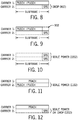
- PUSCH/PUCCH is transmitted to a first eNB while SRS is transmitted to a second eNB by a UE in the same subframe i (as shown in Fig. 8 )
- the following options can be used by the UE, in some implementations.
- PUSCH/PUCCH (PUSCH or PUCCH or both) is carried on carrier 1, while SRS is carried on carrier 2, both in the same subframe i .
- Carriers 1 and 2 are provided by different eNBs.
- SRS is dropped (at 802) if there is a PUSCH/PUCCH transmission on any component carrier and on any connection in subframe i of regardless of whether there is a UE power constrained condition or not.
- a UE power constrained condition is present if the total uplink power (of various uplink transmissions of the UE) exceeds a power threshold.
- a second option SRS is transmitted if there is no power constrained condition, and scaled if there is a power constrained condition.
- the prioritization rule for Option 2 specifies that a PUSCH/PUCCH transmission has a higher priority than an SRS transmission.
- the PUSCH can be rate matched or a shortened PUCCH can be used for each subframe that carries an SRS that is configured for any component carrier or any wireless connection.
- An SRS that is configured for any component carrier or any wireless connection of a UE refers to an SRS that can be sent by the UE in a given serving cell, where this SRS is useable by the network to determine the channel condition, timing advance, and so forth, for all serving cells for the UE.
- PUSCH/PUCCH is not transmitted in an orthogonal frequency-division multiplexing (OFDM) symbol or other portion of subframe i that is configured for carrying SRS.
- OFDM orthogonal frequency-division multiplexing
- the last OFDM symbol (at 902) on carrier 1 is not used for transmitting PUSCH/PUCCH.
- the prioritization rule of Option 3 specifies that PUSCH/PUCCH is not transmitted in the portion that overlaps with an SRS transmission.
- an eNB can determine whether an SRS is dropped or not by a UE in a subframe if the eNB knows the scheduled PUCCH/PUSCH transmissions on other cells.
- the first eNB expecting an SRS from the UE may have to blindly detect if the SRS was dropped or not.
- the likelihood of dropping SRS using Option 1 is increased.
- an SRS is transmitted if there is no power constrained condition, and power scaled down if there is a power constrained condition.
- Power scaling down an SRS transmission power may cause pessimistic uplink CSI estimation and thus lower uplink data rate.
- Pessimistic uplink CSI estimation refers to the eNB making a determination that a channel condition is worse than it actually is.
- the lower data rate may be temporary and also depends on the amount of power scaling.
- the timing advance estimation can continue.
- PUSCH transmission to a UE with multiple wireless connections is rate matched or PUCCH transmission is shortened in each subframe carrying an SRS; the PUSCH rate matching or PUCCH shortening is performed in all serving cells of the UE. Since periodic and aperiodic subframes carrying SRS are semi-statically configured for a UE, such configuration can be exchanged among eNBs serving the UE. This can allow a deterministic behavior of SRS transmission at the UE and SRS reception at the eNBs.
- Solution 2 addresses cases where an SRS transmitted by a UE to one eNB is applicable to all component carriers or wireless connections. In different cases, multiple SRS transmissions can be sent by the UE to different eNBs. Solution 3 can be applied in such cases. As with Solution 2, Solution 3 is applicable where the UE uplink timings to different serving eNBs are aligned.
- Solution 3 is triggered in response to the UE detecting that the total uplink power of the UE for SRS transmissions would exceed P ⁇ CMAX ( i ) .
- the UE scales P ⁇ SRS, c ( i ) for a serving cell c in subframe i such that the condition ⁇ c w i ⁇ P ⁇ SRS , c i ⁇ P ⁇ CMAX i is satisfied, where P ⁇ SRS, c ( i ) is the linear value of P SRS,c ( i ), P SRS, c ( i ) is the UE transmit power for the SRS transmitted on subframe i for serving cell c , and w ( i ) is a scaling factor of P ⁇ SRS, c ( i ) for serving cell c where 0 ⁇ w ( i ) ⁇ 1. Note that w ( i ) values can be the same across serving cells.
- FIG. 10 An example of the scaling of power of SRS transmissions is shown in Fig. 10 , which shows multiple SRS transmissions on different carriers 1 and 2 (of different eNBs) in subframe i.
- the scaling of power of the SRS transmissions is represented as 1002.
- the prioritization rule for the scenario represented by Fig. 10 specifies that multiple SRS transmissions to multiple eNBs are power scaled when a total uplink power of the UE exceeds the power threshold.
- the power sharing control based on power scaling of SRS transmissions among two or more eNBs described above is complementary to the power sharing control among serving cells for carrier aggregation of a particular eNB.
- Each of one or more eNBs can have multiple serving cells provided by respective component carriers of the carrier aggregation.
- a challenge posed by the UE being served by multiple eNBs is that the SRS pattern (e.g . time window(s) or frequency(ies) on which SRS transmissions may be made) of a first eNB may not be known to a second eNB.
- the SRS pattern e.g . time window(s) or frequency(ies) on which SRS transmissions may be made
- the pattern can be shared between eNBs, so that all serving eNBs can derive the power level to expect for the SRS.
- aperiodic SRS such information exchange may not be feasible.
- each eNB can define an SRS pattern for all possible SRS transmissions for a given UE, and exchange the SRS pattern among the eNBs.
- a first eNB can only schedule SRS transmissions within a first SRS pattern, which specifies that SRS transmissions can occur in first subframe(s), and not in other subframe(s).
- the SRS pattern can also specify the frequency or frequencies on which an SRS transmission is made.
- a second eNB can only schedule SRS transmission within a second SRS pattern, which specifies that SRS transmissions can occur in second subframe(s), and not in other subframe(s).
- the first and second SRS patterns may or may not overlap.
- the UE scales the power of the SRS transmission of the first eNB as if there is concurrently an SRS transmission to the second eNB (even though there may not be an actual SRS transmission to the second eNB in that subframe).
- Solution 4 is also applicable in cases where the UE uplink timings to different serving eNBs are aligned.
- Solution 4 is applied in cases where concurrent physical random access channel (PRACH) and PUSCH/PUCCH transmissions are made in the same subframe, but to different eNBs.
- PRACH is used by a UE to perform a random access procedure of an eNB to access the eNB such that the UE can establish a communications session.
- Fig. 11 An example of concurrent PRACH and PUSCH/PUCCH transmissions is illustrated in Fig. 11 , where carrier 1 carries PRACH, while carrier 2 carries PUSCH/PUCCH. Carriers 1 and 2 are provided by different eNBs. In such cases, the UE can adjust (at 1102) the transmission power of PUSCH/PUCCH so that the total uplink power of the UE does not exceed P CMAX . Effectively, according to Fig. 11 , a PRACH transmission is assigned a higher priority than a PUSCH/PUCCH transmission.
- Solution 5 is also applicable in cases where the UE uplink timings to different serving eNBs are aligned.
- Solution 5 can be applied where there are concurrent PRACH and SRS transmissions to different eNBs (over carriers 1 and 2 as shown in Fig. 12 ) in the same subframe.
- the PRACH transmission is assigned a higher priority than the SRS transmission.
- the UE power scales or drops (at 1202) the SRS transmission if the total uplink power exceeds a power threshold in a subframe.
- the eNB expecting an SRS transmission may have to blindly estimate whether or not the SRS transmission was dropped by the UE by measuring the power level over the REs of the subframe that are expected to carry the SRS transmission. If the measured power level is below a certain threshold, the eNB expecting the SRS transmission can assume that the SRS transmission was dropped by the eNB as part of the uplink power sharing control.
- the SRS transmission is still transmitted but with a scaled down transmit power.
- the eNB would not have to perform any SRS drop detection.
- the uplink CSI may be estimated pessimistically, resulting in a reduced uplink data rate. Unlike in the dropping case, the timing advance estimation can continue.
- Solution 6 is applicable when serving eNBs of a UE are not time synchronized or their distances to the UE differ by a large amount (a difference in distance greater than a specified threshold). As a result, the timing of uplink transmissions at the UE to the eNBs may not be aligned.
- the misalignment can be by more than a specified amount, such as more than one OFDM symbol in length.
- Figs. 13A and 13B The misalignment of uplink transmissions of the UE to different eNBs is shown in two example scenarios in Figs. 13A and 13B , where carriers 1 and 2 are provided by the different eNBs.
- the UE transmits a PUSCH/PUCCH in subframe i to a first eNB, and transmits a PUSCH/PUCCH in subframe j to a second eNB, where subframes i and j overlap by some amount.
- the UE When the UE is scheduled to transmit PUCCH/PUSCH to more than one eNB, and the transmissions overlap in time, the UE power scales or drops (at 1302) the PUCCH/PUSCH transmission on one of the carriers (carrier 2 in the example of Fig. 13A ) if the total uplink power exceeds a power threshold.
- the following prioritization rule can be applied. If a PUSCH/PUCCH transmission with a higher priority is transmitted earlier than a PUSCH/PUCCH transmission with a lower priority, and the total uplink power of the UE exceeds a power threshold in the overlap time period, the lower priority PUSCH/PUCCH transmission is power scaled or dropped across the whole subframe of the lower priority PUSCH/PUCCH (subframe j in Fig. 13A ). In other words, the power adjustment is performed over a full transmission time period (corresponding to the length of an entire subframe).
- the prioritization rule can specify a different action under a different scenario, as shown in Fig. 13B . If the PUSCH/PUCCH transmission of a lower priority (on carrier 2 in the Fig. 13B example) is transmitted earlier than the PUSCH/PUCCH transmission of a higher priority, and the total uplink power of the UE exceeds the power threshold in the overlap time period, the lower priority PUSCH/PUCCH transmission in the overlap region (1310 in Fig. 13B ) is either power scaled or dropped. In other words, the power adjustment in this latter case is performed over a part of the full transmission time period, where the part is the overlapping time region.
- a UE is scheduled to transmit PUSCH/PUCCH/PRACH (PUSCH or PUCCH or PRACH) in subframe i and SRS in subframe j to multiple respective eNBs, and such uplink transmissions overlap in time (as shown in Fig. 14 ), the UE scales or drops (at 1402) the SRS transmission if the total uplink power exceeds the power threshold.
- PUSCH/PUCCH/PRACH PUSCH or PUCCH or PRACH
- an eNB is made aware of the SRS transmission being dropped by the UE so that incorrect uplink channel interpretation can be avoided, and the eNB does not have to perform blind detection to decide whether the SRS was transmitted or not.
- an eNB can perform pessimistic uplink CSI estimation, which can result in a reduced uplink data rate.
- the lower data rate may be temporary and also depends on the amount of power scaling.
- timing advance estimation can continue.
- a different technique of addressing the Fig. 14 scenario is to define a pattern for SRS transmission (such as in the time-frequency domain), and to allow eNBs to notify each other of such SRS patterns.
- An SRS pattern can specify the time window(s) and frequency(ies) on which an SRS may be transmitted.
- An SRS transmitted within a specified SRS pattern is protected, such that the SRS would not be dropped.
- An SRS transmitted outside of the SRS pattern may be dropped if the SRS overlaps with PUSCH/PUCCH/PRACH.
- the discussion above refer to eNBs that do not employ carrier aggregation.
- at least one of the eNBs to which a UE has established concurrent wireless connections can be configured with carrier aggregation.
- the primary cell (Pcell) and secondary cell(s) (Scell(s)) of a given eNB may have different timing advances to the UE; thus, the primary and secondary cells belong to different timing advance groups.
- Pcell primary cell
- Scell(s) secondary cell(s) of a given eNB may have different timing advances to the UE; thus, the primary and secondary cells belong to different timing advance groups.
- the relative subframe timing between eNBs should be accounted for in grouping serving cells into timing advance groups.
- the grouping can be performed by a macro eNB storing subframe/radio frame timing offset information between the macro eNB and affiliated small cell eNBs.
- Control signaling can be defined for uplink power sharing control, where the control signaling is sent from an eNB to a UE.
- An example of the control signaling is Radio Resource Control (RRC) signaling, which is exchanged between RRC layers in the eNB and the UE.
- RRC signaling is used to broadcast system information to UEs, send a paging message to a UE, establish a radio connection with a UE, and so forth.
- the RRC signaling can also be used to notify a UE which carrier (of a specific eNB) is to be used for reference signal received power (RSRP) measurement and pathloss calculation.
- the UE uses the RSRP measurement and pathloss calculation to calculate the UE's uplink transmit power.
- RSRP reference signal received power
- the following options may be used for RRC signaling to the UE the carrier to be used for RSRP measurement and pathloss calculation.
- An RSRP measurement measures the average received power over resource elements that carry cell-specific reference signals.
- Pathloss calculation refers to calculating a signal loss due to propagation of the signal over the downlink from the eNB to the UE.
- a first option there is no coordination among two or more eNBs to which the UE is concurrently connected.
- the eNBs e.g. macro eNB and small cell eNB
- the eNBs can each perform its own RRC signaling formulation independently, and transmit corresponding power control RRC messages (identifying the carrier(s) to be used for RSRP measurement and pathloss calculation) to the UE independently.
- the UE receives power control messages from multiple eNBs, and the UE can perform power control for each of the eNBs based on the respective received uplink power sharing control messages.
- a power control RRC message is formulated in a first eNB (e.g. small cell eNB) identifying the carrier to be used for RSRP measurement and pathloss calculation.
- the power control RRC message is passed by the first eNB to a second eNB (e.g. macro eNB).
- the power control RRC message is then transmitted by the second eNB to the UE. This gives the second eNB an opportunity to modify the power control message formulated by the first eNB.
- the second eNB can be a central coordinator in such implementations.
- Fig. 16 depicts a computing system 1600, which can be any of the UE 110, macro eNB 104, or small cell eNB 108 discussed above.
- the computing system 1600 includes uplink power sharing control machine-readable instructions 1602, which are executable on a processor (or multiple processors) 1604 to perform various tasks discussed above.
- a processor can include a microprocessor, microcontroller, processor module or subsystem, programmable integrated circuit, programmable gate array, or another control or computing device.
- the processor(s) 1604 can be coupled to a communication interface (or communication component) 1606 to perform communications.
- the communication interface 1606 can perform wireless communication over an air interface, or perform wired communication over a wired connection.
- the computing system 1600 can include multiple communication interfaces 1606 to communicate with respective different network nodes.
- the processor(s) 1604 can also be coupled to a computer-readable or machine-readable storage medium (or storage media) 1608, for storing data and instructions.
- the storage medium or storage media 1608 can include different forms of memory including semiconductor memory devices such as dynamic or static random access memories (DRAMs or SRAMs), erasable and programmable read-only memories (EPROMs), electrically erasable and programmable read-only memories (EEPROMs) and flash memories; magnetic disks such as fixed, floppy and removable disks; other magnetic media including tape; optical media such as compact disks (CDs) or digital video disks (DVDs); or other types of storage devices.
- DRAMs or SRAMs dynamic or static random access memories
- EPROMs erasable and programmable read-only memories
- EEPROMs electrically erasable and programmable read-only memories
- flash memories magnetic disks such as fixed, floppy and removable disks
- other magnetic media including tape optical media such as compact disks (CDs) or digital video
- the instructions discussed above can be provided on one computer-readable or machine-readable storage medium, or alternatively, can be provided on multiple computer-readable or machine-readable storage media distributed in a large system having possibly plural nodes.
- Such computer-readable or machine-readable storage medium or media is (are) considered to be part of an article (or article of manufacture).
- An article or article of manufacture can refer to any manufactured single component or multiple components.
- the storage medium or media can be located either in the machine running the machine-readable instructions, or located at a remote site from which machine-readable instructions can be downloaded over a network for execution.
Abstract
Description
- As the demand for wireless data communication using wireless user equipments (UEs) has increased, wireless access service providers are increasingly facing challenges in meeting capacity demands in regions where the density of users is relatively high. To address capacity issues, small cells have been developed. A small cell (or multiple small cells) can operate within a coverage area of a larger cell, referred to as a macro cell. A small cell has a coverage area that is smaller than the coverage area of the macro cell.
- If small cells are deployed, then communications with UEs can be offloaded from the macro cell to the small cells. In this way, data communication capacity is increased to better meet data communication demands in regions of relatively high densities of UEs.
- In general, according to some implementations, a method of a user equipment (UE) comprise detecting that an aggregate of calculated uplink transmit power of the UE exceeds a threshold, and in response to the detecting, adjusting a power of at least one of a plurality of frequency-division multiplexing (FDM)-based uplink transmissions of the UE over corresponding wireless connections with respective wireless access network nodes.
- In general, according to further implementations, a wireless access network node comprises a communication component to communicate wirelessly with a UE, and at least one processor configured to use information relating to uplink power sharing control at the UE to process an uplink transmission from the UE, where the uplink transmission is one of a plurality of frequency-division multiplexing (FDM)-based uplink transmissions over corresponding wireless connections with respective wireless access network nodes.
- In general, according to further implementations, a UE includes a communication component to communicate wirelessly with a wireless access network node, and at least one processor configured to detect that an aggregate of calculated uplink transmit power of the UE exceeds a threshold, and in response to the detecting, adjust a power of at least one of a plurality of frequency-division multiplexing (FDM)-based uplink transmissions of the UE over corresponding wireless connections with respective wireless access network nodes.
- Other or alternative features will become apparent from the following description, from the drawings, and from the claims.
- Some embodiments are described with respect to the following figures.
-
Fig. 1 is a schematic diagram of an example arrangement that includes macro cells and small cells, in accordance with some implementations. -
Fig. 2 is a flow diagram of an uplink transmit power sharing control process according to some implementations. -
Figs. 3-15 are schematic diagrams of applying uplink transmit power sharing control to concurrent uplink transmissions from a UE, according to various implementations. -
Fig. 16 is a block diagram of an example computing system that is able to incorporate some implementations. -
Fig. 1 illustrates an example arrangement that includes network nodes that are part of a mobile communications network that supports wireless communications with user equipments (UEs). A node can refer to an electronic device that is capable of sending, receiving, and forwarding information over a communication channel, and of performing designated tasks. Amacro cell 102 corresponds to a coverage area provided by a macro wirelessaccess network node 104. A coverage area can refer to a region where mobile services can be provided by a network node to a target level. A wireless access network node is responsible for performing wireless transmissions and receptions with UEs. In addition, a number ofsmall cells 106 are depicted as being within the coverage area of themacro cell 102. Eachsmall cell 106 corresponds to a coverage area provided by a respective small cell wirelessaccess network node 108. One of the small cells is labeled 106-1, and the corresponding small cell wireless access network node is labeled 108-1. - In the ensuing discussion, a small cell can refer to a cell whose coverage area is smaller than the coverage area provided by a larger cell, which is also referred to as a macro cell. In some examples, the frequency at which the macro wireless
access network node 104 operates can be lower than that of a small cell wirelessaccess network node 108. A lower frequency allows a greater geographic reach for wireless signals transmitted by the macro wirelessaccess network node 104. On the other hand, at a higher frequency, wireless signals transmitted by the small cellwireless access nodes 108 propagate smaller distances. As a result,small cells 106 can be deployed in relatively close proximity to each other. - More generally, the
macro cell 102 can use a frequency that is different from one or more frequencies of thesmall cells 106. At least some of thesmall cells 106 can use different frequencies. - A wireless user equipment (UE) 110 within the coverage area of the small cell 106-1 is able to wirelessly communicate with the small cell wireless access network node 108-1. The UE 110 is also able to wirelessly communicate with the macro wireless
access network node 104. Examples of the UE 110 can include any of the following: a smart phone, a personal digital assistant, a notebook computer, a tablet computer, or any other device that is capable of wireless communications. Although just one UE 110 is depicted inFig. 1 , it is noted that multiple UEs may be present in coverage areas of each of thesmall cells 106 as well as within the coverage area of themacro cell 102. - Also, although reference is made to macro and small cell wireless access network nodes in the present discussion, it is noted that techniques or mechanisms according to some implementations can also be applied to other types of wireless access network nodes, such as in deployments without small cells.
- A first
wireless connection 112 can be established between the UE 110 and the small cell wireless access network node 108-1. In addition, a secondwireless connection 114 can be established between the UE 110 and the macro wirelessaccess network node 104. In such an arrangement, the UE 110 is considered to have established dual concurrent wireless connections with the macro wirelessaccess network node 104 and the small cell wireless access network node 108-1. In other examples, the UE 110 can establish multiple concurrent wireless connections with the macro wirelessaccess network node 104 and with multiple small cell wirelessaccess network nodes 108. -
Fig. 1 also shows abackhaul link 116 between the macro wirelessaccess network node 104 and each of the small cell wirelessaccess network nodes 108. Thebackhaul link 116 can represent a logical communication link between two nodes; thebackhaul link 116 can either be a direct point-to-point link or can be routed through another communication network or node. In some examples, thebackhaul link 116 is a wired link. In other examples, thebackhaul link 116 is a wireless link. - In some implementations, the macro cell 102 (and more specifically the macro wireless access network node 104) can provide all of the control plane functions, while a small cell 106 (more specifically the corresponding small cell wireless access network node 108) provides at least a portion of the user plane functions for a dual-connection capable UE (a UE that is capable of concurrently connecting to both macro and small cells). Note that the macro wireless
access network node 104 can also provide user plane functions for the dual-connection capable UE. - Control plane functions involve exchanging certain control signaling between the macro wireless
access network node 104 and the UE 110 to perform specified control tasks, such as any or some combination of the following: network attachment of a UE, authentication of the UE, setting up radio bearers for the UE, mobility management to manage mobility of the UE (mobility management includes at least determining which infrastructure network nodes will create, maintain or drop uplink and downlink connections carrying control or user plane information as a UE moves about in a geographic area), performance of a handover decision based on neighbor cell measurements sent by the UE, transmission of a paging message to the UE, broadcasting of system information, control of UE measurement reporting, and so forth. Although examples of control tasks and control messages in a control plane are listed above, it is noted that in other examples, other types of control messages and control tasks can be provided. More generally, the control plane can perform call control and connection control functions, and can provide messaging for setting up calls or connections, supervising calls or connections, and releasing calls or connections. - User plane functions relate to communicating traffic data (e.g. voice data, user data, application data, etc.) between the UE and a wireless access network node. User plane functions can also include exchanging control messages between a wireless access network node and a UE associated with communicating the traffic data, flow control, error recovery, and so forth.
- A small cell connection can be added to or removed from a UE under the control of the macro wireless
access network node 104. In some implementations, the action of adding or removing a small cell for a UE can be transparent to acore network 118 of the mobile communications network. Thecore network 118 includes acontrol node 120 and one ormore data gateways 122. The data gateway(s) 122 can be coupled to an external packet data network (PDN) 124, such as the Internet, a local area network (LAN), a wide area network (WAN), and so forth. - Note that a legacy UE (a UE that is not capable of establishing multiple concurrent wireless connections with both a macro cell and one or more small cells) can connect to either a macro cell or a small cell using traditional wireless connection techniques.
- When a UE moves under the coverage of a
small cell 106, the macro wirelessaccess network node 104 may decide to offload some of the user plane traffic to the small cell. This offload is referred to as a data offload. When a data offload has been performed from themacro cell 104 to thesmall cell 106, then a UE that has a dual connection can transmit or receive data to and from the corresponding small cell wirelessaccess network node 108. Additionally, the UE 110 can also communicate user plane traffic with the macro wirelessaccess network node 104. Although reference is made to data offload to one small cell, it is noted that in other examples, themacro cell 104 can perform data offload for the UE 110 to multiple small cells. - In some examples, the data offload causes the offloaded data to be communicated between the macro wireless
access network node 104 and the respective small cell wirelessaccess network node 108 over therespective backhaul link 116. In this case, the data offload involves themacro cell 102, without involving thecore network 118. In other words, the data offload is transparent to thecore network 118. - In other examples, the data offload may be performed at the
data gateway 122, such as a serving gateway (discussed further below). In this case, the serving gateway can send some of the UE's user plane traffic directly to the small cell wirelessaccess network node 108 over a link between the small cell wirelessaccess network node 108 and thedata gateway 122, such as the S1-U link according to the Long-Term Evolution (LTE) standards. In this case, the data offload is visible to thecore network 118. - As another example, the
data gateway 122 can send data to the small cell wirelessaccess network node 108 via the macro wirelessaccess network node 104. In this case, the macro wirelessaccess network node 104 acts as a router for forwarding data communicated between thedata gateway 122 and the small cell wirelessaccess network node 108. - A total uplink transmit power threshold can be specified for uplink transmissions of a UE to the network. In implementations where a UE has concurrent wireless connections with multiple wireless access network nodes (e.g. multiple concurrent connections with the macro wireless
access network node 104 and one or more small cell wireless access network nodes 108), it may be possible for the uplink transmissions over the multiple wireless connections to cause power to exceed the total uplink transmit power threshold. - In accordance with some implementations, techniques or mechanisms are provided to allow for control of the power of uplink transmissions from a UE such that the total power of the uplink transmissions of the UE no longer exceeds the total uplink transmit power threshold. Such control can be referred to as uplink transmit power sharing control.
- In scenarios where there are concurrent wireless connections with multiple wireless access network nodes, uplink transmit power sharing control can be complicated by the fact that one wireless access network node is not aware of control signals that have been scheduled by another wireless access network node for uplink transmission by a UE. This is especially true in deployments where the backhaul link (e.g. 116 in
Fig. 1 ) between wireless access network nodes has a relatively high latency, which prevents the wireless access network nodes from informing each other in a timely manner of how the wireless access network nodes are interacting with UEs. - In an example, the UE (which has concurrent wireless connections with multiple wireless access network nodes) may drop transmission of a given uplink control signal to reduce uplink transmit power. However, a wireless access network node may not be able to determine whether an undetected uplink control signal within a given transmission time period was dropped by the UE as part of uplink transmit power sharing control, or was lost due to an uplink transmission error (because of poor wireless link conditions or for another reason). This is due to the fact that each of the multiple wireless access network nodes has a respective scheduler, such as a Medium Access Control (MAC) scheduler, for scheduling uplink control signals for transmission by the UE.
- In contrast, in a traditional carrier aggregation scenario, just one wireless access network node would be involved; as a result, a scheduler, e.g. MAC scheduler, in the wireless access network node is able to determine what uplink control signals have been scheduled by the scheduler for uplink transmissions. In a single-wireless access network node carrier aggregation scenario, the wireless access network node is able to predict whether an undetected control signal was dropped due to uplink transmit power sharing control at a UE. Note that with carrier aggregation, the component carriers of the carrier aggregation share the same MAC layer and upper layers above the MAC layer in the wireless access network node. Different physical layers are provided for the different component carriers.
- In accordance with some implementations, in arrangements where a UE has concurrent wireless connections with multiple wireless access network nodes, prioritization rules can be specified for uplink transmit power sharing control so that each eNB is able to determine what to expect from the UE on an uplink. Various prioritization rules are described further below. A prioritization rule can be pre-configured in the UE. Alternatively, a prioritization rule can be signaled by an eNB to the UE.
- When receiving an uplink transmission from a UE, an eNB is able to process the received uplink transmission based on information relating to uplink transmit power sharing control at the UE. For example, the information relating to the uplink transmit power sharing control can be at least one prioritization rule used by the UE for adjusting one or more uplink transmissions when a power threshold is exceeded. In this way, the eNB is able to accurately detect the received uplink transmission. For example, the eNB would be able to determine when an uplink transmission's power has been lowered, or when an uplink transmission has been dropped.
-
Fig. 2 illustrates an example uplink transmit power sharing control process that can be performed by a UE according to at least one prioritization rule. The UE detects (at 202) that an aggregate of calculated uplink transmit power (or total calculated uplink transmit power) of concurrent uplink transmissions of the UE over wireless connections (that involve multiple wireless access network nodes) exceeds a threshold. A UE is able to calculate uplink transmit power for each of the concurrent uplink transmissions. Concurrent uplink transmissions refer to uplink transmissions of the UE where at least some portion of the uplink transmissions overlap one another in time (in other words, the uplink transmissions can overlap partially or fully). Each of at least two of the wireless access network nodes includes a corresponding separate scheduler (e.g. MAC scheduler) for individually scheduling uplink transmissions of the UE. - In some implementations, the uplink transmissions are frequency-division-multiplexing (FDM)-based uplink transmissions. FDM is a technique by which a frequency bandwidth can be divided into non-overlapping frequency sub-bands, which can be used to carry uplink transmissions. Each uplink transmission may utilize one or more frequency sub-bands. Examples of FDM techniques include orthogonal FDM (OFDM) techniques, single-carrier frequency-division multiple access (SC-FDMA) techniques, and so forth. More generally, an FDM-based uplink transmission refers to an uplink transmission that is carried in a frequency portion(s). Furthermore, after two FDM-based uplink transmissions are constructed, they may be mapped to share the same carrier frequency, or mapped to different carrier frequencies.
- In response to detecting that the aggregate of calculated uplink transmit power exceeds the threshold, the process of
Fig. 2 adjusts (at 204) a power of at least one of the uplink transmissions of the UE over the corresponding wireless connections with respective wireless access network nodes. In some implementations, the adjusting is according to at least one prioritization rule specifying priorities of the uplink transmissions. The adjusting of power of at least one of the multiple uplink transmissions of the UE can include one or more of the following: (1) reducing the power (also referred to as "scaling down" or simply "scaling" of the power) of the at least one uplink transmission; or (2) dropping the at least one uplink transmission. - A UE can establish just one wireless connection with a wireless access network node, or multiple concurrent wireless connections with the wireless access network node. For example, the wireless access network node can provide carrier aggregation, which allows a UE to communicate with the wireless access network node using multiple component carriers (at respective different frequencies) provided by the wireless access network node. The component carriers are aggregated together to provide carrier aggregation. The UE can establish multiple concurrent wireless connections with the wireless access network node on the respective component carriers.
- One or more cells can be provided on a given component carrier. In the context of carrier aggregation, a "cell" can refer generally to a coverage area provided by a wireless access network node on the respective component carrier. One of the component carriers is configured as a primary cell, or Pcell, while the remaining component carrier(s) is (are) configured as secondary cell(s), or Scell(s). The primary cell is used to communicate certain control information to UEs served by the primary cell.
- If carrier aggregation is not performed, then each of multiple concurrent wireless connections of a UE is established with an individual corresponding wireless access network node. On the other hand, if at least one wireless access network node supports carrier aggregation, then a subset of the multiple concurrent wireless connections are established over component carriers of the wireless access network node that supports carrier aggregation. A remainder of the multiple wireless connections is (are) established with at least one other wireless access network node. For example, concurrent uplink transmissions over wireless connections with multiple wireless access network nodes can include multiple uplink transmissions over wireless connections with different component carriers (cells) of a first wireless access network node, and an uplink transmission over a wireless connection with a second wireless access network node.
- The prioritization rule specifying priorities of the uplink transmissions can specify priorities of uplink transmissions over wireless connections provided over different component carriers as well as with multiple wireless access network nodes.
- In the ensuing discussion, reference is made to mobile communications networks that operate according to the Long-Term Evolution (E-UTRA) standards as provided by the Third Generation Partnership Project (3GPP). The E-UTRA standards are also referred to as the Evolved Universal Terrestrial Radio Access (E-UTRA) standards.
- Although reference is made to E-UTRA in the ensuing discussion, it is noted that techniques or mechanisms according to some implementations can be applied to other wireless access technologies.
- In an E-UTRA network, a wireless access network node can be implemented as an enhanced Node B (eNB), which includes functionalities of a base station and base station controller. Thus, in an E-UTRA network, a macro wireless access network node is referred to as a macro eNB. In an E-UTRA network, small cell wireless access network nodes can be referred to as small cell eNBs.
- In an E-UTRA network, the
control node 120 in thecore network 118 can be implemented as a mobility management entity (MME). An MME is a control node for performing various control tasks associated with an E-UTRA network. For example, the MME can perform idle mode UE tracking and paging, bearer activation and deactivation, selection of a serving gateway (discussed further below) when the UE initially attaches to the E-UTRA network, handover of the UE between macro eNBs, authentication of a user, generation and allocation of a temporary identity to a UE, and so forth. In other examples, the MME can perform other or alternative tasks. - In an E-UTRA network, the data gateway(s) 122 of the
core network 118 can include a serving gateway (SGW) and a packet data network gateway (PDN-GW). The SGW routes and forwards traffic data packets of a UE served by the SGW. The SGW can also act as a mobility anchor for the user plane during handover procedures. The SGW provides connectivity between the UE and thePDN 124. The PDN-GW is the entry and egress point for data communicated between a UE in the E-UTRA network and a network element coupled to thePDN 124. There can be multiple PDNs and corresponding PDN-GWs. Moreover, there can be multiple MMEs and SGWs. - The eNBs that a UE connects to may use different configurations. In a first example, the UE may connect to a first eNB in a frequency division duplex (FDD) mode and a second eNB in a time division duplex (TDD) mode. In FDD mode, uplink and downlink transmissions are separated in the frequency domain, by transmitting uplink data using a first carrier frequency, and transmitting downlink data using a second carrier frequency. In TDD mode, both uplink and downlink transmissions occur on the same carrier frequency; however, uplink and downlink transmissions are separated in the time domain, by sending uplink and downlink transmissions in different time periods.
- In another example, the UE may connect to multiple eNBs in TDD mode; however, the connections to the multiple eNBs may employ different TDD uplink-downlink configurations. In TDD mode, one of several different uplink-downlink configurations may be used for communications between a UE and an eNB. A particular uplink-downlink configuration can specify that, within a frame, a first subset of subframes in the frame is used for uplink transmissions, and a second subset of subframes in the frame is used for downlink transmissions. Different uplink-downlink configurations can employ different numbers of uplink and downlink subframes. A subframe refers to a segment of an overall frame that is used for carrying data and control information, where the segment has a specified time length.
- In another example, at least one eNB may deploy carrier aggregation, such that the eNB provides multiple serving cells corresponding to the multiple component carriers of the carrier aggregation. The different serving cells have use TDD uplink-downlink configurations.
- In the various examples above as well as in other examples, the uplink transmit power of a UE is shared between all concurrent uplink transmissions. Some dual-connection examples (where the UE is concurrently connected to
eNB 1 and eNB2) are provided below: - Both eNB1 and eNB2 operate in the FDD mode. In this scenario, the uplink transmit power sharing is applied to all uplink subframes that the UE simultaneously transmit to eNB1 and eNB2. For full duplex communications (where uplink and downlink transmissions can simultaneously occur), the uplink transmit power sharing applies to all scheduled uplink subframes. For half duplex communications (where uplink and downlink transmissions occur at different times), the uplink transmit power sharing applies to the subframes dedicated to uplink transmission (instead of downlink transmissions).
-
eNB 1 operates in the FDD mode, and eNB2 operates in the TDD mode. During times when the UE is transmitting uplink subframes to eNB2, the uplink transmit power sharing control is applied to the concurrent uplink subframes sent to both eNB1 and eNB2. During times when the UE is transmitting uplink subframes to only eNB1, all of the uplink power is available for the wireless connection(s) witheNB 1. - Both
eNB 1 and eNB2 operate in the TDD mode, but the uplink-downlink configurations ofeNB 1 and eNB2 are different. During times when the UE is sending uplink subframes to botheNB 1 and eNB2, the uplink transmit power sharing control is applied across the two eNBs. However, during times when the UE is sending uplink subframes to just one of the two eNBs, all of the uplink power is available for the wireless connection(s) with the one eNB. - There are various example total uplink transmit power thresholds that may be exceeded by multiple concurrent uplink transmissions by a UE over respective wireless connections involving two or more eNBs. An example total uplink transmit power threshold is PPowerClass, which is a maximum uplink transmit power threshold specified by an eNB for a given UE power class. Another example total uplink transmit power threshold is P̂CMAX, which can be configured by a UE.
- The following describes various solutions that can be applied. Some of the solutions are applicable in cases where a UE's uplink timings to multiple eNBs are aligned. More specifically, the boundaries of uplink subframes communicated by the UE to the eNBs are time aligned from the UE's perspective. Time alignment of subframes (from the UE's perspective) can occur when the eNBs are time synchronized with each other, and the distances between the UE and the eNBs are approximately the same.
- Other solutions described above are applicable to cases where a UE's uplink timings to multiple eNBs are not aligned. For example, the uplink subframes from the UE to the multiple eNBs may not have their subframe boundaries aligned from the UE's perspective. Misalignment can occur when the eNBs are not time synchronized with each other. Even in cases where the eNBs are time synchronized, the uplink subframes to the eNBs may not be aligned due to substantially different distances from the eNBs to the UE (which results in different timing advances for the UE's communications with the respective eNBs).
- Furthermore, an eNB that the UE is connected to can further be configured with carrier aggregation. The serving cells provided by the component carriers of the eNB can belong to different timing advance groups. Different timing advances are applied in the different timing advance groups due to the different propagation delays for communications of the UE with the different serving cells. The different propagation delays in the different serving cells means that the uplink subframes of the UE sent in the different serving cells would be timing misaligned.
-
Solution 1 is applicable to cases where a UE has concurrent uplink transmissions of certain control and traffic channels, such as a physical uplink control channel (PUCCH) and a physical uplink shared channel (PUSCH).Solution 1 can be applied for cases where the uplink timings to different serving eNBs are aligned. - A PUCCH is used to carry certain types of uplink control information (UCI). UCI includes as examples, a scheduling request (SR), an Ack/Nack (acknowledgement or negative acknowledgment) of receipt of downlink data, a channel state information (CSI) for indicating a channel condition, such as modulation level and coding rate, rank and precoding matrix indications in case of multiple transmit antennas deployment at an eNB, as observed by the UE, and so forth. UCI can be carried by PUCCH or PUSCH.
- A PUSCH is used to carry traffic data. In addition, uplink control information (UCI) can also be embedded in the PUSCH. The UCI can include the same control signaling as carried in a PUCCH. Note that a PUSCH can be sent with or without UCI.
- In the ensuing discussion, it is assumed that the UE has PUCCH transmission(s) on a set of one or more serving cells J, PUSCH transmission(s) with UCI on a set of one or more serving cells K, and PUSCH transmission(s) without UCI on one or more other serving cells C. A "serving cell" can refer to a cell provided by a single-carrier eNB, or a cell provided by a component carrier from among multiple component carriers of a carrier aggregation provided by an eNB. In other examples, other combinations of uplink transmissions can be made by the UE.
- In the foregoing scenario, if the total (aggregate) transmit power of the UE is detected to exceed a threshold, such as P̂CMAX (i), the UE may prioritize the uplink transmissions in the following order, where (1) indicates a highest priority level, and (5) indicates a lowest priority level:
- (1) PUCCH transmission with Ack/Nack (with or without CSI, e.g. PUCCH format 1a, 1b, 2a, 2b, or 3);
- (2) PUSCH transmission with Ack/Nack (with or without CSI);
- (3) PUSCH transmission with CSI only, without Ack/Nack;
- (4) PUCCH transmission with CSI only, without Ack/Nack (e.g. PUCCH format 2);
- (5) PUSCH transmission without UCI.
- The foregoing provides an example of a prioritization rule. Although a specific number of different types of uplink transmissions with respective different priority levels are listed above, there can be different numbers of different types of uplink transmissions with corresponding priority levels in other examples.
- According to the foregoing prioritization rule, a PUCCH or a PUSCH that carries acknowledgement information (e.g. ACK/NACK) is assigned a higher priority because a loss of the acknowledgement information would cause either PUSCH retransmission of downlink packets, or downlink packet loss if the maximum number of retransmissions has been reached.
- Periodic CSI reports are carried on a PUCCH, and aperiodic CSI reports are carried on a PUSCH. Aperiodic CSI reporting is considered to be more important than periodic CSI information, and thus a PUSCH carrying CSI (but no Ack/Nack) is assigned a higher priority than a PUCCH carrying CSI (but no Ack/Nack). A PUSCH without any UCI is assigned a lowest priority.
- If there is a group of multiple uplink transmissions from the UE to respective serving cells within each priority level, then one of two different power sharing techniques can be applied to this group of uplink transmissions. With a first technique, equal power scaling can be applied, where the same factor is applied to each uplink transmission of the group. With a second technique, cell-dependent power scaling can be applied, where factors applied to the uplink transmissions of the group depend on the respective serving cells. For example, a first factor can be applied to an uplink transmission of the group to a first serving cell, while a second factor can be applied to an uplink transmission of the group to a second serving cell. For example, a first uplink transmission of the group to the first serving cell can include a PUSCH carrying delay-sensitive traffic data (e.g. voice-over-Internet Protocol traffic data), while a second uplink transmission of the group to the second serving cell can include a PUSCH carrying delay-insensitive traffic data (e.g. web browsing traffic). In this case, the cell-dependent power scaling applies a greater factor to the first uplink transmission than a factor applied to the second uplink transmission. For example, let P 1 and P 2 be respectively the desired transmit power of the first uplink transmission and the desired transmit power of the second uplink transmission, and w 1 P 1 and w 2 P 2 be respectively the actual transmit power of the first uplink transmission and the actual transmit power of the second uplink transmission after scaling, then the factor w 1 is greater than the factor w 2.
- Alternatively, instead of or in addition to defining priority levels for different types of uplink transmissions as discussed above, prioritization can be based on eNBs to which the uplink transmissions are sent. For example, uplink transmission(s) to a first eNB may be assigned a higher priority than uplink transmission(s) to a second, different eNB.
- For the following discussions, it is assumed that the UE may have the following concurrent uplink transmissions in subframe i:
- PUCCH transmission(s) with Ack/Nack on a set of one or more serving cells J 1 ⊆ J ;
- PUCCH transmission(s) without Ack/Nack on one or more serving cells J 2 = J - J 1;
- PUSCH transmission(s) with UCI containing Ack/Nack on a set of one or more serving cells K 1 ⊆ K ;
- PUSCH transmission(s) with UCI not containing Ack/Nack on a set of one or more serving cells K 2 = K - K 1;
- PUSCH transmission(s) without UCI on a set of one or more serving cells C.
- Acknowledgement information that can be carried in a PUCCH transmission or PUSCH transmission includes Ack for positively acknowledging receipt of a downlink subframe, or a Nack to negatively acknowledge receipt of a downlink subframe (in other words, Nack indicates to the eNB that the downlink subframe sent by the eNB was not successfully received by the UE). Note that in the figures, for simplicity, PUSCH carrying uplink control information other than Ack/Nack is labeled as "PUSCH with CSI UCI", which may include SR or other uplink control information.
- In accordance with some implementations,
Solution 1 causes the power of uplink transmissions with lower priority to be adjusted (by either reducing the power of the lower priority uplink transmission or dropping the uplink transmission altogether), to bring the total uplink transmission power within a specified threshold. Adjusting the power of lower priority uplink transmissions protects higher priority uplink transmissions, to ensure that higher priority uplink transmissions can be successfully received by the network. -
Fig. 3 shows an example in which multiple carriers (1-6) are used for carrying respective uplink transmissions. It is assumed that the uplink transmissions are concurrent transmissions in subframe i. Carriers 1-6 can be carriers associated with different eNBs. In some examples, two or more of the carriers can be component carriers of a carrier aggregation provided by one eNB. Thus, the six carriers depicted in the example ofFig. 3 can be provided by two or more eNBs. - In a first scenario, if the total uplink power of the UE would exceed P̂CMAX (i), the UE scales down (at 302) the power P̂ PUSCH,c (i) for a serving cell c ∈ C in subframe i such that the condition

- As depicted in
Fig. 3 , the power scaling (at 302) causes a reduction of the power of the PUSCH transmissions on carriers 5 and 6 (these are the uplink transmissions that do not carry UCI). - In some examples, the parameter wc (i) can be independent of serving cell c. In this case, the remaining power (power remaining after uplink transmissions of PUCCH(s) and PUSCH(s) carrying UCI) is equally divided among the PUSCH transmissions that do not carry UCI. Alternatively, the parameter wc (i) can be based on factors such as the path loss to the serving cell c. For example, the PUSCH transmission to a close-in eNB may be assigned a higher priority. As another example, wc (i) can be based on a quality-of-service (QoS) configuration associated with each PUSCH. For example, delay-sensitive traffic may be prioritized over delay-insensitive traffic, or an uplink retransmission may be prioritized over a new uplink transmission.
- The foregoing provides a solution to address the first scenario where the total uplink power of all of the uplink transmissions of the UE would exceed P̂CMAX (i).
- A second scenario applies where

- In this second scenario, just the uplink transmissions of PUCCH and PUSCH with UCI would cause the power threshold to be exceeded; in other words, even if the UE does not transmit any PUSCH without UCI, the power threshold would still be exceeded by the remaining uplink transmissions. In this second scenario, as shown in
Fig. 4 , the UE drops (at 402) PUSCH transmission without UCI, which inFig. 4 are provided on carriers 5 and 6. In addition, the UE scales down (at 404) P̂ PUCCH,j (i) without Ack/Nack for the serving cells J 2 in subframe i such that the condition
- In a third scenario, the total uplink power of the PUCCH(s) carrying acknowledgement information (Ack/Nack) and the PUSCH(s) carrying UCI would exceed the power threshold, as expressed by

- In this third scenario, as shown in
Fig. 5 , the following uplink transmissions are dropped (at 402, 502): the PUSCH transmissions without UCI on carriers 5 and 6, and the PUCCH transmission without Ack/Nack on carrier 3. The UE scales down (at 504) the PUSCH transmission(s) with CSI but without Ack/Nack on serving cell(s) K 2 in subframe i such that the condition
- In a fourth scenario, the total transmission power of PUCCH with Ack/Nack and PUSCH with Ack/Nack would exceed the power threshold, as expressed by

- In this case, as shown in
Fig. 6 , the following uplink transmissions are dropped (at 402, 502, 602): the PUSCH transmissions without UCI on carriers 5 and 6, the PUCCH transmission without Ack/Nack on carrier 3, the PUSCH transmission without Ack/Nack on serving cell K 2 (carrier 4). The PUSCH transmission with Ack/Nack on serving cell K 1 can be scaled down (at 604) such that the condition
- In a fifth scenario, just the uplink transmission of PUCCH carrying Ack/Nack would cause the power threshold to be exceeded, as expressed by

- In this fifth scenario, in addition to dropping (at 402, 502, 602) various uplink transmissions as discussed above,
Fig. 7 also shows that the UE scales down (at 702) the PUSCH carrying Ack/Nack, and scales down (at 704) the PUCCH carrying Ack/Nack. The power scaling (at 702) of the PUSCH carrying Ack/Nack is performed differently from the power scaling (at 604) shown inFig. 6 . InFig. 7 , the scaling of power involves the UE setting the power of data REs of the PUSCH k (k ∈ K 1) equal to zero. The scaling (at 702, 704) P̂ PUCCH,j(i) for j ∈ J 1 and P̂ PUSCH,k(i) for k ∈ K 1 in subframe i is performed such that the condition
-
Solution 1 discussed above refers to a solution that can be applied where a UE transmits PUCCH(s) and PUSCH(s), but not a sounding reference signal (SRS). However,Solution 2 is applied in cases where SRS is sent by a UE. The SRS is measured by an eNB to determine uplink channel quality, to determine a timing advance, and for other purposes. -
Solution 2 is also applicable in cases where the UE uplink timings to different serving eNBs are aligned. - When PUSCH/PUCCH is transmitted to a first eNB while SRS is transmitted to a second eNB by a UE in the same subframe i (as shown in
Fig. 8 ), the following options can be used by the UE, in some implementations. - In
Fig. 8 , it is assumed that PUSCH/PUCCH (PUSCH or PUCCH or both) is carried oncarrier 1, while SRS is carried oncarrier 2, both in the same subframe i.Carriers - In a second option (Option 2), SRS is transmitted if there is no power constrained condition, and scaled if there is a power constrained condition. Effectively, the prioritization rule for
Option 2 specifies that a PUSCH/PUCCH transmission has a higher priority than an SRS transmission. - In a third option (Option 3), the PUSCH can be rate matched or a shortened PUCCH can be used for each subframe that carries an SRS that is configured for any component carrier or any wireless connection. An SRS that is configured for any component carrier or any wireless connection of a UE refers to an SRS that can be sent by the UE in a given serving cell, where this SRS is useable by the network to determine the channel condition, timing advance, and so forth, for all serving cells for the UE.
- An example is depicted in
Fig. 9 , where PUSCH/PUCCH is not transmitted in an orthogonal frequency-division multiplexing (OFDM) symbol or other portion of subframe i that is configured for carrying SRS. In the example ofFig. 9 , the last OFDM symbol (at 902) oncarrier 1 is not used for transmitting PUSCH/PUCCH. The prioritization rule of Option 3 specifies that PUSCH/PUCCH is not transmitted in the portion that overlaps with an SRS transmission. - Using
Option 1, an eNB can determine whether an SRS is dropped or not by a UE in a subframe if the eNB knows the scheduled PUCCH/PUSCH transmissions on other cells. However, when independent MAC schedulers are used in respective eNBs, it may be impractical for a first eNB to know the PUCCH/PUSCH scheduling of a second eNB. Thus, the first eNB expecting an SRS from the UE may have to blindly detect if the SRS was dropped or not. In addition, if there are more than two cells and many PUCCH/PUSCH transmissions on other cells, the likelihood of droppingSRS using Option 1 is increased. - Using
Option 2, an SRS is transmitted if there is no power constrained condition, and power scaled down if there is a power constrained condition. Power scaling down an SRS transmission power may cause pessimistic uplink CSI estimation and thus lower uplink data rate. Pessimistic uplink CSI estimation refers to the eNB making a determination that a channel condition is worse than it actually is. However, the lower data rate may be temporary and also depends on the amount of power scaling. In addition, the timing advance estimation can continue. - Using Option 3, PUSCH transmission to a UE with multiple wireless connections is rate matched or PUCCH transmission is shortened in each subframe carrying an SRS; the PUSCH rate matching or PUCCH shortening is performed in all serving cells of the UE. Since periodic and aperiodic subframes carrying SRS are semi-statically configured for a UE, such configuration can be exchanged among eNBs serving the UE. This can allow a deterministic behavior of SRS transmission at the UE and SRS reception at the eNBs.
-
Solution 2 addresses cases where an SRS transmitted by a UE to one eNB is applicable to all component carriers or wireless connections. In different cases, multiple SRS transmissions can be sent by the UE to different eNBs. Solution 3 can be applied in such cases. As withSolution 2, Solution 3 is applicable where the UE uplink timings to different serving eNBs are aligned. - Solution 3 is triggered in response to the UE detecting that the total uplink power of the UE for SRS transmissions would exceed P̂CMAX (i). In response to such detection, the UE scales P̂ SRS,c (i) for a serving cell c in subframe i such that the condition

- An example of the scaling of power of SRS transmissions is shown in
Fig. 10 , which shows multiple SRS transmissions ondifferent carriers 1 and 2 (of different eNBs) in subframe i. The scaling of power of the SRS transmissions is represented as 1002. The prioritization rule for the scenario represented byFig. 10 specifies that multiple SRS transmissions to multiple eNBs are power scaled when a total uplink power of the UE exceeds the power threshold. - In some implementations, the power sharing control based on power scaling of SRS transmissions among two or more eNBs described above is complementary to the power sharing control among serving cells for carrier aggregation of a particular eNB. Each of one or more eNBs can have multiple serving cells provided by respective component carriers of the carrier aggregation. A challenge posed by the UE being served by multiple eNBs is that the SRS pattern (e.g. time window(s) or frequency(ies) on which SRS transmissions may be made) of a first eNB may not be known to a second eNB. For periodic SRS (SRS sent on a periodic basis), the pattern can be shared between eNBs, so that all serving eNBs can derive the power level to expect for the SRS. For aperiodic SRS, such information exchange may not be feasible.
- An example solution to avoid unknown SRS power scaling is for each eNB to define an SRS pattern for all possible SRS transmissions for a given UE, and exchange the SRS pattern among the eNBs. For example, a first eNB can only schedule SRS transmissions within a first SRS pattern, which specifies that SRS transmissions can occur in first subframe(s), and not in other subframe(s). The SRS pattern can also specify the frequency or frequencies on which an SRS transmission is made. Similarly, a second eNB can only schedule SRS transmission within a second SRS pattern, which specifies that SRS transmissions can occur in second subframe(s), and not in other subframe(s). The first and second SRS patterns may or may not overlap.
- Whenever an SRS transmission of the first eNB overlaps with the second SRS pattern, the UE scales the power of the SRS transmission of the first eNB as if there is concurrently an SRS transmission to the second eNB (even though there may not be an actual SRS transmission to the second eNB in that subframe).
- Solution 4 is also applicable in cases where the UE uplink timings to different serving eNBs are aligned.
- Solution 4 is applied in cases where concurrent physical random access channel (PRACH) and PUSCH/PUCCH transmissions are made in the same subframe, but to different eNBs. PRACH is used by a UE to perform a random access procedure of an eNB to access the eNB such that the UE can establish a communications session.
- An example of concurrent PRACH and PUSCH/PUCCH transmissions is illustrated in
Fig. 11 , wherecarrier 1 carries PRACH, whilecarrier 2 carries PUSCH/PUCCH.Carriers Fig. 11 , a PRACH transmission is assigned a higher priority than a PUSCH/PUCCH transmission. - Solution 5 is also applicable in cases where the UE uplink timings to different serving eNBs are aligned.
- Solution 5 can be applied where there are concurrent PRACH and SRS transmissions to different eNBs (over
carriers Fig. 12 ) in the same subframe. The PRACH transmission is assigned a higher priority than the SRS transmission. As shown inFig. 12 , the UE power scales or drops (at 1202) the SRS transmission if the total uplink power exceeds a power threshold in a subframe. - In cases where the SRS transmission is dropped, the eNB expecting an SRS transmission may have to blindly estimate whether or not the SRS transmission was dropped by the UE by measuring the power level over the REs of the subframe that are expected to carry the SRS transmission. If the measured power level is below a certain threshold, the eNB expecting the SRS transmission can assume that the SRS transmission was dropped by the eNB as part of the uplink power sharing control.
- In cases where the SRS transmission is power scaled, the SRS transmission is still transmitted but with a scaled down transmit power. The eNB would not have to perform any SRS drop detection. In this case, the uplink CSI may be estimated pessimistically, resulting in a reduced uplink data rate. Unlike in the dropping case, the timing advance estimation can continue.
- Solution 6 is applicable when serving eNBs of a UE are not time synchronized or their distances to the UE differ by a large amount (a difference in distance greater than a specified threshold). As a result, the timing of uplink transmissions at the UE to the eNBs may not be aligned. The misalignment can be by more than a specified amount, such as more than one OFDM symbol in length.
- The misalignment of uplink transmissions of the UE to different eNBs is shown in two example scenarios in
Figs. 13A and 13B , wherecarriers Fig. 13A , the UE transmits a PUSCH/PUCCH in subframe i to a first eNB, and transmits a PUSCH/PUCCH in subframe j to a second eNB, where subframes i and j overlap by some amount. When the UE is scheduled to transmit PUCCH/PUSCH to more than one eNB, and the transmissions overlap in time, the UE power scales or drops (at 1302) the PUCCH/PUSCH transmission on one of the carriers (carrier 2 in the example ofFig. 13A ) if the total uplink power exceeds a power threshold. - In some implementations, the following prioritization rule can be applied. If a PUSCH/PUCCH transmission with a higher priority is transmitted earlier than a PUSCH/PUCCH transmission with a lower priority, and the total uplink power of the UE exceeds a power threshold in the overlap time period, the lower priority PUSCH/PUCCH transmission is power scaled or dropped across the whole subframe of the lower priority PUSCH/PUCCH (subframe j in
Fig. 13A ). In other words, the power adjustment is performed over a full transmission time period (corresponding to the length of an entire subframe). - The prioritization rule can specify a different action under a different scenario, as shown in
Fig. 13B . If the PUSCH/PUCCH transmission of a lower priority (oncarrier 2 in theFig. 13B example) is transmitted earlier than the PUSCH/PUCCH transmission of a higher priority, and the total uplink power of the UE exceeds the power threshold in the overlap time period, the lower priority PUSCH/PUCCH transmission in the overlap region (1310 inFig. 13B ) is either power scaled or dropped. In other words, the power adjustment in this latter case is performed over a part of the full transmission time period, where the part is the overlapping time region. - In a different scenario, as shown in
Fig. 14 , a UE is scheduled to transmit PUSCH/PUCCH/PRACH (PUSCH or PUCCH or PRACH) in subframe i and SRS in subframe j to multiple respective eNBs, and such uplink transmissions overlap in time (as shown inFig. 14 ), the UE scales or drops (at 1402) the SRS transmission if the total uplink power exceeds the power threshold. - If the SRS transmission is dropped when it overlaps with a PUSCH/PUCCH/PRACH transmission, an eNB is made aware of the SRS transmission being dropped by the UE so that incorrect uplink channel interpretation can be avoided, and the eNB does not have to perform blind detection to decide whether the SRS was transmitted or not.
- If the SRS transmission is power scaled, and there is a power constrained condition (the total uplink power of the UE exceeds the power threshold), an eNB can perform pessimistic uplink CSI estimation, which can result in a reduced uplink data rate. However, the lower data rate may be temporary and also depends on the amount of power scaling. In addition, timing advance estimation can continue.
- In alternative implementations, a different technique of addressing the
Fig. 14 scenario is to define a pattern for SRS transmission (such as in the time-frequency domain), and to allow eNBs to notify each other of such SRS patterns. An SRS pattern can specify the time window(s) and frequency(ies) on which an SRS may be transmitted. An SRS transmitted within a specified SRS pattern is protected, such that the SRS would not be dropped. An SRS transmitted outside of the SRS pattern may be dropped if the SRS overlaps with PUSCH/PUCCH/PRACH. - When a UE is scheduled to transmit PRACH and PUSCH/PUCCH to multiple respective eNBs (e.g. in subframe i and subframe j, respectively, over
carriers Fig. 15 ), and the transmissions overlap in time (as shown inFig. 15 ), the UE power scales (at 1502) the PUCCH/PUSCH transmission if the total uplink power exceeds the power threshold. - For simplicity, the discussion above (with respect to
Figs. 12-15 ) refer to eNBs that do not employ carrier aggregation. In general, at least one of the eNBs to which a UE has established concurrent wireless connections can be configured with carrier aggregation. Further, the primary cell (Pcell) and secondary cell(s) (Scell(s)) of a given eNB may have different timing advances to the UE; thus, the primary and secondary cells belong to different timing advance groups. When the UE is concurrently connected to two or more eNBs, several different uplink subframe timings are possible, for an individual eNB or across eNBs. When multiple eNBs are involved, the relative subframe timing between eNBs should be accounted for in grouping serving cells into timing advance groups. For example, the grouping can be performed by a macro eNB storing subframe/radio frame timing offset information between the macro eNB and affiliated small cell eNBs. Once the timing of different serving cells is specified from the perspective of UE, prioritization in an overlapping region (where concurrent uplink transmissions are made by the UE) can use any of the various solutions described above in response to the total uplink power of the UE exceeding a power threshold. - Control signaling can be defined for uplink power sharing control, where the control signaling is sent from an eNB to a UE. An example of the control signaling is Radio Resource Control (RRC) signaling, which is exchanged between RRC layers in the eNB and the UE. Generally, RRC signaling is used to broadcast system information to UEs, send a paging message to a UE, establish a radio connection with a UE, and so forth.
- In accordance with some implementations, in an arrangement in which the UE has concurrent wireless connections with multiple eNBs, the RRC signaling can also be used to notify a UE which carrier (of a specific eNB) is to be used for reference signal received power (RSRP) measurement and pathloss calculation. The UE uses the RSRP measurement and pathloss calculation to calculate the UE's uplink transmit power. In cases where a UE sends uplink transmissions to multiple eNBs, the following options may be used for RRC signaling to the UE the carrier to be used for RSRP measurement and pathloss calculation.
- An RSRP measurement measures the average received power over resource elements that carry cell-specific reference signals. Pathloss calculation refers to calculating a signal loss due to propagation of the signal over the downlink from the eNB to the UE.
- In a first option (Option 1), there is no coordination among two or more eNBs to which the UE is concurrently connected. In some implementations, the eNBs (e.g. macro eNB and small cell eNB) can each perform its own RRC signaling formulation independently, and transmit corresponding power control RRC messages (identifying the carrier(s) to be used for RSRP measurement and pathloss calculation) to the UE independently. In such implementations, the UE receives power control messages from multiple eNBs, and the UE can perform power control for each of the eNBs based on the respective received uplink power sharing control messages.
- In a second option (Option 2), there is coordination among two or more eNBs to which the UE is concurrently connected. In such cases, a power control RRC message is formulated in a first eNB (e.g. small cell eNB) identifying the carrier to be used for RSRP measurement and pathloss calculation. The power control RRC message is passed by the first eNB to a second eNB (e.g. macro eNB). The power control RRC message is then transmitted by the second eNB to the UE. This gives the second eNB an opportunity to modify the power control message formulated by the first eNB. The second eNB can be a central coordinator in such implementations.
-
Fig. 16 depicts acomputing system 1600, which can be any of theUE 110,macro eNB 104, orsmall cell eNB 108 discussed above. Thecomputing system 1600 includes uplink power sharing control machine-readable instructions 1602, which are executable on a processor (or multiple processors) 1604 to perform various tasks discussed above. A processor can include a microprocessor, microcontroller, processor module or subsystem, programmable integrated circuit, programmable gate array, or another control or computing device. - The processor(s) 1604 can be coupled to a communication interface (or communication component) 1606 to perform communications. For example, the
communication interface 1606 can perform wireless communication over an air interface, or perform wired communication over a wired connection. In some cases, thecomputing system 1600 can includemultiple communication interfaces 1606 to communicate with respective different network nodes. - The processor(s) 1604 can also be coupled to a computer-readable or machine-readable storage medium (or storage media) 1608, for storing data and instructions. The storage medium or
storage media 1608 can include different forms of memory including semiconductor memory devices such as dynamic or static random access memories (DRAMs or SRAMs), erasable and programmable read-only memories (EPROMs), electrically erasable and programmable read-only memories (EEPROMs) and flash memories; magnetic disks such as fixed, floppy and removable disks; other magnetic media including tape; optical media such as compact disks (CDs) or digital video disks (DVDs); or other types of storage devices. Note that the instructions discussed above can be provided on one computer-readable or machine-readable storage medium, or alternatively, can be provided on multiple computer-readable or machine-readable storage media distributed in a large system having possibly plural nodes. Such computer-readable or machine-readable storage medium or media is (are) considered to be part of an article (or article of manufacture). An article or article of manufacture can refer to any manufactured single component or multiple components. The storage medium or media can be located either in the machine running the machine-readable instructions, or located at a remote site from which machine-readable instructions can be downloaded over a network for execution. - In the foregoing description, numerous details are set forth to provide an understanding of the subject disclosed herein. However, implementations may be practiced without some or all of these details. Other implementations may include modifications and variations from the details discussed above. It is intended that the appended claims cover such modifications and variations.
- Additionally, the application is to be taken to extend to include the following numbered statements:
- 1. A method of a user equipment (UE), the method comprising:
- detecting that an aggregate of calculated uplink transmit power of the UE exceeds a threshold; and
- in response to the detecting, adjusting a power of at least one of a plurality of frequency-division multiplexing (FDM)-based uplink transmissions of the UE over corresponding wireless connections with respective wireless access network nodes.
- 2. The method of
statement 1 wherein at least two of the wireless access network nodes have respective separate schedulers. - 3. The method of
statement 1, wherein the adjusting comprises reducing the power of the at least one uplink transmission or dropping the at least one uplink transmission. - 4. The method of
statement 1, wherein the uplink transmissions are concurrent uplink transmissions that overlap fully or partially in time. - 5. The method of
statement 1, wherein a first of the wireless access network nodes provides carrier aggregation having component carriers, and the concurrent uplink transmissions include plural uplink transmissions over wireless connections with the component carriers of the first wireless access network node. - 6. The method of
statement 1, wherein the adjusting is according to at least one prioritization rule specifying priority of at least one of the uplink transmissions. - 7. The method of statement 6, wherein the adjusting is according to the at least one prioritization rule specifying that a first uplink control channel transmission or traffic channel transmission containing acknowledgment information has a higher priority than a second uplink control channel transmission or traffic channel transmission without acknowledgment information.
- 8. The method of statement 6, wherein the adjusting is according to the at least one prioritization rule specifying that a first uplink traffic channel transmission containing uplink control information has a higher priority than a second uplink traffic channel transmission without uplink control information.
- 9. The method of statement 6, wherein the adjusting is according to the at least one prioritization rule specifying that an uplink traffic channel transmission containing channel state information but without acknowledgment information has a higher priority than an uplink control channel transmission containing channel state information but without acknowledgement information.
- 10. The method of statement 6, wherein the adjusting is according to the at least one prioritization rule specifying that a first resource element associated with acknowledgement information contained in an uplink traffic channel transmission has a higher priority than a second resource element with traffic data contained in the uplink traffic channel transmission.
- 11. The method of statement 6, wherein the uplink transmissions comprise a first uplink transmission and a sounding reference signal transmission, wherein the first uplink transmission includes one or both of an uplink traffic channel transmission and an uplink control channel transmission, and wherein the adjusting reduces a power of the sounding reference signal transmission or drops the sounding reference signal transmission.
- 12. The method of statement 6, wherein the uplink transmissions comprise a first uplink transmission and a sounding reference signal transmission, wherein the first uplink transmission comprises one or both of an uplink control transmission and uplink traffic channel transmission, and wherein the adjusting avoids performing the first uplink transmission at a portion of a carrier that coincides with the sounding reference signal transmission.
- 13. The method of statement 6, wherein the uplink transmissions comprise a plurality of sounding reference signal transmissions, and wherein the adjusting reduces a power of at least one of the sounding reference signal transmissions.
- 14. The method of statement 6, wherein the adjusting is according to the at least one prioritization rule specifying that a random access channel transmission has a higher priority than an uplink control channel transmission or an uplink traffic channel transmission.
- 15. The method of statement 6, wherein the adjusting is according to the at least one prioritization rule specifying that a random access channel transmission has a higher priority than a sounding reference signal transmission.
- 16. The method of statement 6, wherein the adjusting is according to the at least one prioritization rule specifying that transmissions to a first wireless access network node has a higher priority than a second wireless access network node.
- 17. The method of
statement 1, wherein the uplink transmissions to the respective wireless access network nodes are time aligned. - 18. The method of
statement 1, wherein the uplink transmissions to the respective wireless access network nodes are time misaligned - 19. The method of
statement 1, wherein the adjusting is performed over a full transmission time interval. - 20. The method of
statement 1, wherein the adjusting is performed over a part of a full transmission time interval. - 21. A wireless access network node comprising:
- a communication component to communicate wirelessly with a user equipment (UE); and
- at least one processor configured to:
- use information relating to uplink power sharing control at the UE to process an uplink transmission from the UE, wherein the uplink transmission is one of a plurality of frequency-division multiplexing (FDM)-based uplink transmissions over corresponding wireless connections with respective wireless access network nodes.
- 22. The method of statement 21, wherein the information relating to the uplink power sharing control includes a prioritization rule specifying priority of the at least one of the plurality of FDM-based uplink transmissions.
- 23. A user equipment (UE) comprising:
- a communication component to communicate wirelessly with a wireless access network node; and
- at least one processor configured to:
- detect that an aggregate of calculated uplink transmit power of the UE exceeds a threshold; and
- in response to the detecting, adjust a power of at least one of a plurality of frequency-division multiplexing (FDM)-based uplink transmissions of the UE over corresponding wireless connections with respective wireless access network nodes.
- 24. The UE of statement 19, wherein the adjusting is according to at least one prioritization rule specifying priority of the at least one of a plurality of uplink transmissions.
Claims (14)
- A method of a user equipment (UE), the method comprising:detecting that an aggregate of calculated uplink transmit power of a plurality of frequency-division multiplexing (FDM)-based uplink transmissions of the UE over corresponding wireless connections with respective wireless access network nodes exceeds a threshold; andin response to the detecting, adjusting a power of multiple uplink transmissions of the plurality of FDM-based uplink transmissions of the UE over the corresponding wireless connections with the respective wireless access network nodes, the adjusting being according to at least one prioritization rule specifying that an uplink transmission containing acknowledgment information has a higher priority than an uplink transmission without acknowledgment information and where the adjusting the power of the multiple uplink transmissions comprises reducing a power of each of the multiple uplink transmissions that are transmitted to corresponding multiple wireless access network nodes without reducing a power of a given uplink transmission that is transmitted to a given wireless access network node different from the multiple wireless access network nodes, wherein the reducing of the power of each of the multiple uplink transmissions comprises setting non-zero values of respective scaling factors for the multiple uplink transmissions, the non-zero values greater than zero and less than one.
- The method of claim 1 wherein at least two of the wireless access network nodes have respective separate schedulers.
- The method of claim 1, further comprising, in response to the detecting, dropping another uplink transmission of the plurality of FDM-based uplink transmissions based on the at least one prioritization rule.
- The method of claim 1, wherein the FDM-based uplink transmissions are concurrent uplink transmissions that overlap fully or partially in time, optionally wherein a first of the wireless access network nodes provides carrier aggregation having component carriers, and the concurrent uplink transmissions include:plural FDM-based uplink transmissions over wireless connections on the component carriers of the first wireless access network node, andan FDM-based uplink transmission over a wireless connection with a second of the wireless access network nodes.
- The method of claim 1, wherein the adjusting is according to the at least one prioritization rule that further specifies one of that:a) a first uplink traffic channel transmission containing uplink control information has a higher priority than a second uplink traffic channel transmission without uplink control information,b) an uplink traffic channel transmission containing channel state information but without acknowledgment information has a higher priority than an uplink control channel transmission containing channel state information but without acknowledgement information,c) a first resource element associated with acknowledgement information contained in an uplink traffic channel transmission has a higher priority than a second resource element with traffic data contained in the uplink traffic channel transmission,d) a random access channel transmission has a higher priority than an uplink control channel transmission or an uplink traffic channel transmission,e) a random access channel transmission has a higher priority than a sounding reference signal transmission, andf) transmissions to a first wireless access network node has a higher priority than transmissions to a second wireless access network node.
- The method of claim 1, wherein the FDM-based uplink transmissions further comprise a sounding reference signal transmission, wherein the given uplink transmission transmission, and wherein the adjusting further comprises dropping the sounding reference signal transmission.
- The method of claim 1, wherein the FDM-based uplink transmissions further comprise a sounding reference signal transmission, wherein the uplink transmission without acknowledgement information comprises one or both of an uplink control transmission and uplink traffic channel transmission, and wherein the adjusting further comprises avoiding performing the given uplink transmission at a portion of a carrier that coincides with the sounding reference signal transmission.
- The method of claim 1, wherein the FDM-based uplink transmissions comprise a plurality of sounding reference signal transmissions, and wherein the adjusting reduces a power of at least one of the sounding reference signal transmissions.
- The method of claim 1, wherein the FDM-based uplink transmissions to the respective wireless access network nodes are time aligned.
- The method of claim 1, wherein the FDM-based uplink transmissions to the respective wireless access network nodes are time misaligned
- The method of claim 1, wherein the adjusting is performed over a part of a full transmission time interval or over a full transmission time interval.
- The method of claim 1, wherein setting the non-zero values of the respective scaling factors is based on respective:a) path losses to corresponding wireless access network nodes to which the multiple uplink transmissions are transmitted, orb) quality-of-service configurations for the multiple uplink transmissions.
- The method of claim 1, wherein the non-zero values of the respective scaling factors are multiplied with respective target transmit powers of the multiple uplink transmissions to determine respective actual transmit powers of the multiple uplink transmissions.
- A user equipment (UE) comprising:a communication interface to communicate wirelessly with wireless access network nodes; andat least one processor configured to perform the method of any preceding claim.
Applications Claiming Priority (3)
| Application Number | Priority Date | Filing Date | Title |
|---|---|---|---|
| US13/957,620 US10932205B2 (en) | 2013-08-02 | 2013-08-02 | Uplink power sharing control |
| EP14748440.6A EP3011782B1 (en) | 2013-08-02 | 2014-07-23 | Uplink power sharing control |
| PCT/US2014/047756 WO2015017205A1 (en) | 2013-08-02 | 2014-07-23 | Uplink power sharing control |
Related Parent Applications (1)
| Application Number | Title | Priority Date | Filing Date |
|---|---|---|---|
| EP14748440.6A Division EP3011782B1 (en) | 2013-08-02 | 2014-07-23 | Uplink power sharing control |
Publications (3)
| Publication Number | Publication Date |
|---|---|
| EP3267743A2 true EP3267743A2 (en) | 2018-01-10 |
| EP3267743A3 EP3267743A3 (en) | 2018-05-02 |
| EP3267743B1 EP3267743B1 (en) | 2022-11-09 |
Family
ID=51299045
Family Applications (2)
| Application Number | Title | Priority Date | Filing Date |
|---|---|---|---|
| EP17189269.8A Active EP3267743B1 (en) | 2013-08-02 | 2014-07-23 | Uplink power sharing control |
| EP14748440.6A Active EP3011782B1 (en) | 2013-08-02 | 2014-07-23 | Uplink power sharing control |
Family Applications After (1)
| Application Number | Title | Priority Date | Filing Date |
|---|---|---|---|
| EP14748440.6A Active EP3011782B1 (en) | 2013-08-02 | 2014-07-23 | Uplink power sharing control |
Country Status (4)
| Country | Link |
|---|---|
| US (3) | US10932205B2 (en) |
| EP (2) | EP3267743B1 (en) |
| CA (1) | CA2920003C (en) |
| WO (1) | WO2015017205A1 (en) |
Cited By (1)
| Publication number | Priority date | Publication date | Assignee | Title |
|---|---|---|---|---|
| CN112399463A (en) * | 2019-08-12 | 2021-02-23 | 海信集团有限公司 | Information reporting method and equipment |
Families Citing this family (48)
| Publication number | Priority date | Publication date | Assignee | Title |
|---|---|---|---|---|
| CN104685955B (en) * | 2012-09-28 | 2019-02-01 | Lg电子株式会社 | Method of uplink transmission and uplink transmitting device |
| KR101844690B1 (en) * | 2013-08-13 | 2018-04-02 | 후지쯔 가부시끼가이샤 | Power control method for uplink channel, user equipment and communication system |
| US9131513B2 (en) | 2013-08-16 | 2015-09-08 | Blackberry Limited | Coordinating allocation of resources for use by small cells |
| EP3036939B1 (en) | 2013-08-19 | 2018-10-03 | BlackBerry Limited | A wireless access network node having an off state |
| US9872257B2 (en) | 2013-09-04 | 2018-01-16 | Lg Electronics Inc. | Method and apparatus for controlling uplink power in wireless communication system |
| US10237047B2 (en) * | 2013-09-18 | 2019-03-19 | Telefonaktiebolaget Lm Ericsson (Publ) | Full duplex communication method and associated radio base station |
| WO2015046782A1 (en) | 2013-09-24 | 2015-04-02 | Lg Electronics Inc. | Mac layer communication for parallel random access procedures of dual connectivity |
| US9497673B2 (en) | 2013-11-01 | 2016-11-15 | Blackberry Limited | Method and apparatus to enable multiple wireless connections |
| US9357377B2 (en) * | 2013-12-04 | 2016-05-31 | Acer Incorporated | Method of managing E-UTRA function of user equipment and related wireless communication system |
| US11743897B2 (en) * | 2013-12-20 | 2023-08-29 | Qualcomm Incorporated | Techniques for configuring uplink channels in unlicensed radio frequency spectrum bands |
| MX364772B (en) * | 2014-03-14 | 2019-05-06 | Intel Corp | Uplink channel transmission in dual connectivity. |
| US9357510B2 (en) * | 2014-03-31 | 2016-05-31 | Qualcomm Incorporated | Power sharing and power headroom reporting in dual connectivity scenarios |
| US20150327243A1 (en) * | 2014-05-08 | 2015-11-12 | Sharp Laboratories Of America, Inc. | Systems and methods for dual-connectivity operation |
| JP6193481B2 (en) * | 2014-05-09 | 2017-09-06 | 株式会社Nttドコモ | User device and transmission control method |
| WO2015178421A1 (en) * | 2014-05-21 | 2015-11-26 | シャープ株式会社 | Terminal device and method |
| WO2016021588A1 (en) * | 2014-08-04 | 2016-02-11 | シャープ株式会社 | Terminal device, base station device, and method |
| US10980045B2 (en) | 2014-10-02 | 2021-04-13 | Qualcomm Incorporated | Techniques for managing power on an uplink component carrier transmitted over a shared radio frequency spectrum band |
| US9749970B2 (en) * | 2015-02-27 | 2017-08-29 | Qualcomm Incorporated | Power control and power headroom for component carrier |
| WO2016182291A1 (en) * | 2015-05-08 | 2016-11-17 | 엘지전자 주식회사 | Method for transmitting or receiving uplink signal in wireless communication system and device therefor |
| US10251132B2 (en) * | 2015-07-23 | 2019-04-02 | Acer Incorporated | Device and method of handling uplink power control for unlicensed serving cell |
| WO2017022802A1 (en) * | 2015-08-06 | 2017-02-09 | シャープ株式会社 | Terminal device, base station device, communication method, and integrated circuit |
| RU2018108676A (en) * | 2015-08-14 | 2019-09-16 | Телефонактиеболагет Лм Эрикссон (Пабл) | METHOD AND DEVICE FOR SEPARATE PLANNING OF DATA TRANSFERS AND REFERENCE SIGNAL ON THE CHANNEL OF THE RISING COMMUNICATION LINES IN THE COMMUNICATION NETWORK |
| CN106685613B (en) * | 2015-11-06 | 2020-04-10 | 电信科学技术研究院 | SRS transmission method and device |
| CN106961703B (en) * | 2016-01-11 | 2021-07-23 | 中兴通讯股份有限公司 | Information transmission method, device and system |
| US10708111B2 (en) | 2016-02-20 | 2020-07-07 | Qualcomm Incorporated | Communication of uplink control information |
| US10278145B2 (en) | 2016-02-20 | 2019-04-30 | Qualcomm Incorporated | Communication of uplink control information |
| KR102458077B1 (en) * | 2016-03-22 | 2022-10-25 | 삼성전자 주식회사 | Method and apparatus for transmitting uplink control information in wireless communication |
| WO2017164623A2 (en) | 2016-03-22 | 2017-09-28 | Samsung Electronics Co., Ltd. | Method and apparatus for transmitting uplink control information in wireless communication system |
| US10536904B2 (en) | 2016-05-09 | 2020-01-14 | Ofinno, Llc | Parallel transmission in a wireless device and wireless network |
| CN107666715B (en) * | 2016-07-28 | 2019-12-24 | 上海朗帛通信技术有限公司 | Method and device in wireless transmission |
| EP3498024B1 (en) * | 2016-08-12 | 2022-04-13 | Telefonaktiebolaget LM Ericsson (publ) | Methods of scheduling transmissions using timing limits and related wireless communication devices |
| WO2018084610A1 (en) * | 2016-11-03 | 2018-05-11 | 엘지전자(주) | Method for transmitting uplink channel in wireless communication system, and apparatus therefor |
| KR102149015B1 (en) * | 2017-01-07 | 2020-08-28 | 엘지전자 주식회사 | Method for transmitting an uplink control channel of a terminal in a wireless communication system and a communication device using the method |
| WO2018128492A1 (en) * | 2017-01-08 | 2018-07-12 | 엘지전자 주식회사 | Uplink signal transmission method of terminal in wireless communication system and device for supporting same |
| CN108112074B (en) * | 2017-05-05 | 2023-07-18 | 中兴通讯股份有限公司 | Information reporting and receiving method and device and computer readable storage medium |
| CN109219052B (en) * | 2017-06-30 | 2021-01-08 | 维沃移动通信有限公司 | Resource information transmission method, related equipment and system |
| US11246151B2 (en) | 2017-08-22 | 2022-02-08 | Lg Electronics Inc. | Method and apparatus for transmitting or receiving wireless signal in wireless communication system |
| CN110535583B (en) * | 2018-08-10 | 2022-05-10 | 中兴通讯股份有限公司 | Transmission determination method, device, base station, terminal and computer readable storage medium |
| CN110881218A (en) * | 2018-09-05 | 2020-03-13 | 维沃移动通信有限公司 | Sounding reference signal transmission method and terminal equipment |
| US11765668B2 (en) * | 2018-09-28 | 2023-09-19 | Apple Inc. | LTE NR power control for EN-DC |
| US11516882B2 (en) * | 2018-09-28 | 2022-11-29 | Apple Inc. | Downlink control for non coherent joint transmission |
| CN111182626A (en) * | 2018-11-09 | 2020-05-19 | 北京展讯高科通信技术有限公司 | Information sending method, user terminal and computer readable storage medium |
| US11381365B2 (en) * | 2019-01-09 | 2022-07-05 | Qualcomm Incorporated | Collision of sounding reference signal (SRS) and physical uplink shared channel (PUSCH) in case of carrier aggregation |
| CN112260805B (en) * | 2019-07-22 | 2023-03-24 | 海能达通信股份有限公司 | Data transmission method and device and electronic equipment |
| CN113811020A (en) * | 2020-06-11 | 2021-12-17 | 中国移动通信有限公司研究院 | Method for reporting and configuring link failure of auxiliary node, terminal and network side equipment |
| CN114007268A (en) * | 2020-07-28 | 2022-02-01 | 华为技术有限公司 | Method and device for transmitting or receiving physical uplink shared channel |
| CN114365517A (en) * | 2020-08-13 | 2022-04-15 | 北京小米移动软件有限公司 | Frequency switching method, frequency switching device and storage medium |
| WO2023014643A1 (en) * | 2021-08-06 | 2023-02-09 | Intel Corporation | Power scaling for uplink full power transmission |
Family Cites Families (25)
| Publication number | Priority date | Publication date | Assignee | Title |
|---|---|---|---|---|
| US7133688B2 (en) * | 2002-04-05 | 2006-11-07 | Lucent Technologies Inc. | Method for improving uplink control channel efficiency in a wireless communication system |
| JP4022625B2 (en) * | 2004-03-08 | 2007-12-19 | 独立行政法人情報通信研究機構 | Communication system, communication method, base station, and mobile station |
| US8670422B2 (en) | 2007-04-30 | 2014-03-11 | Blackberry Limited | System and method for sending and receiving packets |
| US8155023B2 (en) * | 2008-09-26 | 2012-04-10 | Texas Instruments Incorporated | MIMO with reserved subframes in primary and secondary base stations |
| US8787186B2 (en) | 2008-12-12 | 2014-07-22 | Blackberry Limited | Mobility in a distributed antenna system |
| US8644244B2 (en) | 2008-12-12 | 2014-02-04 | Research In Motion Limited | Sensor-based wireless communication systems using compressive sampling |
| KR101697596B1 (en) | 2009-01-29 | 2017-01-18 | 엘지전자 주식회사 | Method and apparatus of controlling transmission power |
| EP2244515A1 (en) * | 2009-04-23 | 2010-10-27 | Panasonic Corporation | Logical channel prioritization procedure for generating multiple uplink transport blocks |
| US8593979B2 (en) * | 2009-07-15 | 2013-11-26 | Lg Electronics Inc. | Method and apparatus for controlling uplink power in a wireless communication system |
| US8982791B2 (en) * | 2009-12-30 | 2015-03-17 | Telefonaktiebolaget L M Ericsson (Publ) | Method of and Node B and user equipment for power control in case of segmentation |
| EP2765730A3 (en) * | 2010-01-08 | 2015-04-15 | Interdigital Patent Holdings, Inc. | Channel state information transmission for multiple carriers |
| US8965442B2 (en) | 2010-05-07 | 2015-02-24 | Qualcomm Incorporated | Uplink power control in aggregated carrier communication systems |
| US8675528B2 (en) * | 2010-11-15 | 2014-03-18 | Sharp Laboratories Of America, Inc. | Configuring uplink control information (UCI) reporting |
| KR101763751B1 (en) * | 2011-01-11 | 2017-08-02 | 삼성전자 주식회사 | Method and appratus of activating/deactivating secondary carriers in mobile communication system using carrier aggregation |
| US9288773B2 (en) * | 2011-04-22 | 2016-03-15 | Qualcomm Incorporated | Methods and apparatus for controlling interference from peer discovery in WWAN |
| CN103733697B (en) | 2011-08-12 | 2018-01-12 | 交互数字专利控股公司 | For Power Control and the method and apparatus of timing advance |
| CN114245444A (en) | 2011-11-04 | 2022-03-25 | 交互数字专利控股公司 | Method and apparatus for power control for wireless transmissions on multiple component carriers associated with multiple timing advances |
| KR20130077387A (en) | 2011-12-29 | 2013-07-09 | 주식회사 팬택 | Method and apparatus of conrtolling transmission power in wireless communication system |
| US8897248B2 (en) * | 2012-01-25 | 2014-11-25 | Ofinno Technologies, Llc | Multicarrier signal transmission in wireless communications |
| US9408125B2 (en) * | 2012-07-05 | 2016-08-02 | Qualcomm Incorporated | Aggregation of data bearers for carrier aggregation |
| US9801163B2 (en) * | 2012-09-10 | 2017-10-24 | Avago Technologies General Ip (Singapore) Pte. Ltd. | Uplink configuration and transmission control in inter-site carrier aggregation |
| US9173147B2 (en) | 2013-01-18 | 2015-10-27 | Blackberry Limited | Communicating data using a local wireless access network node |
| US9444745B2 (en) | 2013-03-08 | 2016-09-13 | Blackberry Limited | Sending data rate information to a wireless access network node |
| US9578671B2 (en) | 2013-03-15 | 2017-02-21 | Blackberry Limited | Establishing multiple connections between a user equipment and wireless access network nodes |
| US9629025B2 (en) | 2013-05-03 | 2017-04-18 | Blackberry Limited | Controlling data offload in response to feedback information |
-
2013
- 2013-08-02 US US13/957,620 patent/US10932205B2/en active Active
-
2014
- 2014-07-23 EP EP17189269.8A patent/EP3267743B1/en active Active
- 2014-07-23 EP EP14748440.6A patent/EP3011782B1/en active Active
- 2014-07-23 WO PCT/US2014/047756 patent/WO2015017205A1/en active Application Filing
- 2014-07-23 CA CA2920003A patent/CA2920003C/en active Active
-
2021
- 2021-02-19 US US17/179,473 patent/US11570721B2/en active Active
-
2023
- 2023-01-26 US US18/160,146 patent/US11910331B2/en active Active
Non-Patent Citations (1)
| Title |
|---|
| None |
Cited By (2)
| Publication number | Priority date | Publication date | Assignee | Title |
|---|---|---|---|---|
| CN112399463A (en) * | 2019-08-12 | 2021-02-23 | 海信集团有限公司 | Information reporting method and equipment |
| CN112399463B (en) * | 2019-08-12 | 2022-02-01 | 海信集团有限公司 | Information reporting method and equipment |
Also Published As
| Publication number | Publication date |
|---|---|
| EP3267743B1 (en) | 2022-11-09 |
| EP3267743A3 (en) | 2018-05-02 |
| US11910331B2 (en) | 2024-02-20 |
| CA2920003C (en) | 2023-01-24 |
| US11570721B2 (en) | 2023-01-31 |
| WO2015017205A1 (en) | 2015-02-05 |
| US20230171707A1 (en) | 2023-06-01 |
| EP3011782A1 (en) | 2016-04-27 |
| US10932205B2 (en) | 2021-02-23 |
| US20150036566A1 (en) | 2015-02-05 |
| EP3011782B1 (en) | 2017-09-06 |
| US20210176715A1 (en) | 2021-06-10 |
| CA2920003A1 (en) | 2015-02-05 |
Similar Documents
| Publication | Publication Date | Title |
|---|---|---|
| US11910331B2 (en) | Uplink power sharing control | |
| US10448374B2 (en) | Power headroom report method of dual-connectivity UE in mobile communication system | |
| US20160100426A1 (en) | Scheduling Requests in Small Cell Networks | |
| CN110291746B (en) | Method and apparatus for controlling radio channel deployment in unlicensed spectrum | |
| US9814002B2 (en) | Apparatus and method for controlling transmission power in wireless communication system | |
| US9924532B2 (en) | Buffer status reporting in small cell networks | |
| US9370020B2 (en) | Methods and systems for scheduling communications in a co-channel network | |
| JP2020092429A (en) | Methods and devices for processing srs in dual connectivity | |
| TW201906454A (en) | Adaptive uplink power control method, device and system in wireless network | |
| JP2019514268A (en) | System and method for SRS switching, transmission and extension | |
| US11843938B2 (en) | Sensing procedures in a wireless communication network | |
| CN106465285B (en) | Transmission power control method and device in wireless communication system | |
| WO2020135273A1 (en) | Power control method and apparatus | |
| US20170280441A1 (en) | Terminal device, base station apparatus, and communications method | |
| US10355846B2 (en) | Methods and nodes for soft cell uplink prioritization | |
| WO2018120064A1 (en) | Transmission apparatus and method capable of suppressing interference information, and communication system | |
| JP2016540447A (en) | Power usage state information transmission method and apparatus | |
| CN116349334A (en) | Dynamic selection between resource allocation techniques for side link transmission and resource allocation techniques based on side link communication reliability | |
| US20220132469A1 (en) | Receiver assisted sidelink resource allocation using an adaptive threshold |
Legal Events
| Date | Code | Title | Description |
|---|---|---|---|
| PUAI | Public reference made under article 153(3) epc to a published international application that has entered the european phase |
Free format text: ORIGINAL CODE: 0009012 |
|
| STAA | Information on the status of an ep patent application or granted ep patent |
Free format text: STATUS: THE APPLICATION HAS BEEN PUBLISHED |
|
| AC | Divisional application: reference to earlier application |
Ref document number: 3011782 Country of ref document: EP Kind code of ref document: P |
|
| AK | Designated contracting states |
Kind code of ref document: A2 Designated state(s): AL AT BE BG CH CY CZ DE DK EE ES FI FR GB GR HR HU IE IS IT LI LT LU LV MC MK MT NL NO PL PT RO RS SE SI SK SM TR |
|
| PUAL | Search report despatched |
Free format text: ORIGINAL CODE: 0009013 |
|
| AK | Designated contracting states |
Kind code of ref document: A3 Designated state(s): AL AT BE BG CH CY CZ DE DK EE ES FI FR GB GR HR HU IE IS IT LI LT LU LV MC MK MT NL NO PL PT RO RS SE SI SK SM TR |
|
| RIC1 | Information provided on ipc code assigned before grant |
Ipc: H04W 52/14 20090101ALN20180323BHEP Ipc: H04W 52/28 20090101ALN20180323BHEP Ipc: H04W 52/36 20090101AFI20180323BHEP Ipc: H04W 52/38 20090101ALN20180323BHEP |
|
| STAA | Information on the status of an ep patent application or granted ep patent |
Free format text: STATUS: REQUEST FOR EXAMINATION WAS MADE |
|
| 17P | Request for examination filed |
Effective date: 20181030 |
|
| RBV | Designated contracting states (corrected) |
Designated state(s): AL AT BE BG CH CY CZ DE DK EE ES FI FR GB GR HR HU IE IS IT LI LT LU LV MC MK MT NL NO PL PT RO RS SE SI SK SM TR |
|
| STAA | Information on the status of an ep patent application or granted ep patent |
Free format text: STATUS: EXAMINATION IS IN PROGRESS |
|
| 17Q | First examination report despatched |
Effective date: 20200205 |
|
| STAA | Information on the status of an ep patent application or granted ep patent |
Free format text: STATUS: EXAMINATION IS IN PROGRESS |
|
| STAA | Information on the status of an ep patent application or granted ep patent |
Free format text: STATUS: EXAMINATION IS IN PROGRESS |
|
| GRAP | Despatch of communication of intention to grant a patent |
Free format text: ORIGINAL CODE: EPIDOSNIGR1 |
|
| STAA | Information on the status of an ep patent application or granted ep patent |
Free format text: STATUS: GRANT OF PATENT IS INTENDED |
|
| RIC1 | Information provided on ipc code assigned before grant |
Ipc: H04W 52/38 20090101ALN20220519BHEP Ipc: H04W 52/28 20090101ALN20220519BHEP Ipc: H04W 52/14 20090101ALN20220519BHEP Ipc: H04W 52/36 20090101AFI20220519BHEP |
|
| INTG | Intention to grant announced |
Effective date: 20220601 |
|
| GRAS | Grant fee paid |
Free format text: ORIGINAL CODE: EPIDOSNIGR3 |
|
| GRAA | (expected) grant |
Free format text: ORIGINAL CODE: 0009210 |
|
| STAA | Information on the status of an ep patent application or granted ep patent |
Free format text: STATUS: THE PATENT HAS BEEN GRANTED |
|
| AC | Divisional application: reference to earlier application |
Ref document number: 3011782 Country of ref document: EP Kind code of ref document: P |
|
| AK | Designated contracting states |
Kind code of ref document: B1 Designated state(s): AL AT BE BG CH CY CZ DE DK EE ES FI FR GB GR HR HU IE IS IT LI LT LU LV MC MK MT NL NO PL PT RO RS SE SI SK SM TR |
|
| REG | Reference to a national code |
Ref country code: GB Ref legal event code: FG4D |
|
| REG | Reference to a national code |
Ref country code: CH Ref legal event code: EP Ref country code: AT Ref legal event code: REF Ref document number: 1531135 Country of ref document: AT Kind code of ref document: T Effective date: 20221115 |
|
| REG | Reference to a national code |
Ref country code: DE Ref legal event code: R096 Ref document number: 602014085512 Country of ref document: DE |
|
| REG | Reference to a national code |
Ref country code: IE Ref legal event code: FG4D |
|
| REG | Reference to a national code |
Ref country code: LT Ref legal event code: MG9D |
|
| REG | Reference to a national code |
Ref country code: NL Ref legal event code: MP Effective date: 20221109 |
|
| REG | Reference to a national code |
Ref country code: AT Ref legal event code: MK05 Ref document number: 1531135 Country of ref document: AT Kind code of ref document: T Effective date: 20221109 |
|
| PG25 | Lapsed in a contracting state [announced via postgrant information from national office to epo] |
Ref country code: SE Free format text: LAPSE BECAUSE OF FAILURE TO SUBMIT A TRANSLATION OF THE DESCRIPTION OR TO PAY THE FEE WITHIN THE PRESCRIBED TIME-LIMIT Effective date: 20221109 Ref country code: PT Free format text: LAPSE BECAUSE OF FAILURE TO SUBMIT A TRANSLATION OF THE DESCRIPTION OR TO PAY THE FEE WITHIN THE PRESCRIBED TIME-LIMIT Effective date: 20230309 Ref country code: NO Free format text: LAPSE BECAUSE OF FAILURE TO SUBMIT A TRANSLATION OF THE DESCRIPTION OR TO PAY THE FEE WITHIN THE PRESCRIBED TIME-LIMIT Effective date: 20230209 Ref country code: LT Free format text: LAPSE BECAUSE OF FAILURE TO SUBMIT A TRANSLATION OF THE DESCRIPTION OR TO PAY THE FEE WITHIN THE PRESCRIBED TIME-LIMIT Effective date: 20221109 Ref country code: FI Free format text: LAPSE BECAUSE OF FAILURE TO SUBMIT A TRANSLATION OF THE DESCRIPTION OR TO PAY THE FEE WITHIN THE PRESCRIBED TIME-LIMIT Effective date: 20221109 Ref country code: ES Free format text: LAPSE BECAUSE OF FAILURE TO SUBMIT A TRANSLATION OF THE DESCRIPTION OR TO PAY THE FEE WITHIN THE PRESCRIBED TIME-LIMIT Effective date: 20221109 Ref country code: AT Free format text: LAPSE BECAUSE OF FAILURE TO SUBMIT A TRANSLATION OF THE DESCRIPTION OR TO PAY THE FEE WITHIN THE PRESCRIBED TIME-LIMIT Effective date: 20221109 |
|
| PG25 | Lapsed in a contracting state [announced via postgrant information from national office to epo] |
Ref country code: RS Free format text: LAPSE BECAUSE OF FAILURE TO SUBMIT A TRANSLATION OF THE DESCRIPTION OR TO PAY THE FEE WITHIN THE PRESCRIBED TIME-LIMIT Effective date: 20221109 Ref country code: PL Free format text: LAPSE BECAUSE OF FAILURE TO SUBMIT A TRANSLATION OF THE DESCRIPTION OR TO PAY THE FEE WITHIN THE PRESCRIBED TIME-LIMIT Effective date: 20221109 Ref country code: LV Free format text: LAPSE BECAUSE OF FAILURE TO SUBMIT A TRANSLATION OF THE DESCRIPTION OR TO PAY THE FEE WITHIN THE PRESCRIBED TIME-LIMIT Effective date: 20221109 Ref country code: IS Free format text: LAPSE BECAUSE OF FAILURE TO SUBMIT A TRANSLATION OF THE DESCRIPTION OR TO PAY THE FEE WITHIN THE PRESCRIBED TIME-LIMIT Effective date: 20230309 Ref country code: HR Free format text: LAPSE BECAUSE OF FAILURE TO SUBMIT A TRANSLATION OF THE DESCRIPTION OR TO PAY THE FEE WITHIN THE PRESCRIBED TIME-LIMIT Effective date: 20221109 Ref country code: GR Free format text: LAPSE BECAUSE OF FAILURE TO SUBMIT A TRANSLATION OF THE DESCRIPTION OR TO PAY THE FEE WITHIN THE PRESCRIBED TIME-LIMIT Effective date: 20230210 |
|
| PG25 | Lapsed in a contracting state [announced via postgrant information from national office to epo] |
Ref country code: NL Free format text: LAPSE BECAUSE OF FAILURE TO SUBMIT A TRANSLATION OF THE DESCRIPTION OR TO PAY THE FEE WITHIN THE PRESCRIBED TIME-LIMIT Effective date: 20221109 |
|
| PG25 | Lapsed in a contracting state [announced via postgrant information from national office to epo] |
Ref country code: SM Free format text: LAPSE BECAUSE OF FAILURE TO SUBMIT A TRANSLATION OF THE DESCRIPTION OR TO PAY THE FEE WITHIN THE PRESCRIBED TIME-LIMIT Effective date: 20221109 Ref country code: RO Free format text: LAPSE BECAUSE OF FAILURE TO SUBMIT A TRANSLATION OF THE DESCRIPTION OR TO PAY THE FEE WITHIN THE PRESCRIBED TIME-LIMIT Effective date: 20221109 Ref country code: EE Free format text: LAPSE BECAUSE OF FAILURE TO SUBMIT A TRANSLATION OF THE DESCRIPTION OR TO PAY THE FEE WITHIN THE PRESCRIBED TIME-LIMIT Effective date: 20221109 Ref country code: DK Free format text: LAPSE BECAUSE OF FAILURE TO SUBMIT A TRANSLATION OF THE DESCRIPTION OR TO PAY THE FEE WITHIN THE PRESCRIBED TIME-LIMIT Effective date: 20221109 Ref country code: CZ Free format text: LAPSE BECAUSE OF FAILURE TO SUBMIT A TRANSLATION OF THE DESCRIPTION OR TO PAY THE FEE WITHIN THE PRESCRIBED TIME-LIMIT Effective date: 20221109 |
|
| REG | Reference to a national code |
Ref country code: DE Ref legal event code: R097 Ref document number: 602014085512 Country of ref document: DE |
|
| PG25 | Lapsed in a contracting state [announced via postgrant information from national office to epo] |
Ref country code: SK Free format text: LAPSE BECAUSE OF FAILURE TO SUBMIT A TRANSLATION OF THE DESCRIPTION OR TO PAY THE FEE WITHIN THE PRESCRIBED TIME-LIMIT Effective date: 20221109 Ref country code: AL Free format text: LAPSE BECAUSE OF FAILURE TO SUBMIT A TRANSLATION OF THE DESCRIPTION OR TO PAY THE FEE WITHIN THE PRESCRIBED TIME-LIMIT Effective date: 20221109 |
|
| PLBE | No opposition filed within time limit |
Free format text: ORIGINAL CODE: 0009261 |
|
| STAA | Information on the status of an ep patent application or granted ep patent |
Free format text: STATUS: NO OPPOSITION FILED WITHIN TIME LIMIT |
|
| 26N | No opposition filed |
Effective date: 20230810 |
|
| PGFP | Annual fee paid to national office [announced via postgrant information from national office to epo] |
Ref country code: GB Payment date: 20230727 Year of fee payment: 10 |
|
| PG25 | Lapsed in a contracting state [announced via postgrant information from national office to epo] |
Ref country code: SI Free format text: LAPSE BECAUSE OF FAILURE TO SUBMIT A TRANSLATION OF THE DESCRIPTION OR TO PAY THE FEE WITHIN THE PRESCRIBED TIME-LIMIT Effective date: 20221109 |
|
| PGFP | Annual fee paid to national office [announced via postgrant information from national office to epo] |
Ref country code: FR Payment date: 20230725 Year of fee payment: 10 Ref country code: DE Payment date: 20230727 Year of fee payment: 10 |
|
| PG25 | Lapsed in a contracting state [announced via postgrant information from national office to epo] |
Ref country code: MC Free format text: LAPSE BECAUSE OF FAILURE TO SUBMIT A TRANSLATION OF THE DESCRIPTION OR TO PAY THE FEE WITHIN THE PRESCRIBED TIME-LIMIT Effective date: 20221109 |
|
| PG25 | Lapsed in a contracting state [announced via postgrant information from national office to epo] |
Ref country code: MC Free format text: LAPSE BECAUSE OF FAILURE TO SUBMIT A TRANSLATION OF THE DESCRIPTION OR TO PAY THE FEE WITHIN THE PRESCRIBED TIME-LIMIT Effective date: 20221109 |
|
| REG | Reference to a national code |
Ref country code: CH Ref legal event code: PL |
|
| PG25 | Lapsed in a contracting state [announced via postgrant information from national office to epo] |
Ref country code: LU Free format text: LAPSE BECAUSE OF NON-PAYMENT OF DUE FEES Effective date: 20230723 |
|
| PG25 | Lapsed in a contracting state [announced via postgrant information from national office to epo] |
Ref country code: LU Free format text: LAPSE BECAUSE OF NON-PAYMENT OF DUE FEES Effective date: 20230723 |