EP3267684A1 - Methods and apparatus for determining quantization parameter predictors from a plurality of neighboring quantization parameters - Google Patents
Methods and apparatus for determining quantization parameter predictors from a plurality of neighboring quantization parameters Download PDFInfo
- Publication number
- EP3267684A1 EP3267684A1 EP17182141.6A EP17182141A EP3267684A1 EP 3267684 A1 EP3267684 A1 EP 3267684A1 EP 17182141 A EP17182141 A EP 17182141A EP 3267684 A1 EP3267684 A1 EP 3267684A1
- Authority
- EP
- European Patent Office
- Prior art keywords
- quantization parameter
- predictor
- quantization
- motion vector
- block
- Prior art date
- Legal status (The legal status is an assumption and is not a legal conclusion. Google has not performed a legal analysis and makes no representation as to the accuracy of the status listed.)
- Granted
Links
- 238000013139 quantization Methods 0.000 title claims abstract description 169
- 238000000034 method Methods 0.000 title claims description 55
- 230000011664 signaling Effects 0.000 claims abstract description 10
- 239000013598 vector Substances 0.000 claims description 54
- 230000006870 function Effects 0.000 description 83
- 238000004891 communication Methods 0.000 description 36
- 230000008569 process Effects 0.000 description 24
- 238000013459 approach Methods 0.000 description 20
- 238000010586 diagram Methods 0.000 description 14
- 230000008901 benefit Effects 0.000 description 12
- 230000000875 corresponding effect Effects 0.000 description 11
- 238000005192 partition Methods 0.000 description 9
- 230000000007 visual effect Effects 0.000 description 7
- 230000004048 modification Effects 0.000 description 4
- 238000012986 modification Methods 0.000 description 4
- 230000008859 change Effects 0.000 description 3
- 238000012545 processing Methods 0.000 description 3
- 238000013461 design Methods 0.000 description 2
- 238000001914 filtration Methods 0.000 description 2
- 230000000873 masking effect Effects 0.000 description 2
- 230000000153 supplemental effect Effects 0.000 description 2
- 238000004364 calculation method Methods 0.000 description 1
- 239000000470 constituent Substances 0.000 description 1
- 230000002596 correlated effect Effects 0.000 description 1
- 238000013500 data storage Methods 0.000 description 1
- 238000009795 derivation Methods 0.000 description 1
- 230000006872 improvement Effects 0.000 description 1
- 230000003993 interaction Effects 0.000 description 1
- 239000011159 matrix material Substances 0.000 description 1
- 238000005457 optimization Methods 0.000 description 1
- 230000008520 organization Effects 0.000 description 1
- 230000008447 perception Effects 0.000 description 1
- 230000002093 peripheral effect Effects 0.000 description 1
- 230000009467 reduction Effects 0.000 description 1
- 238000000638 solvent extraction Methods 0.000 description 1
- 230000007704 transition Effects 0.000 description 1
Images


Classifications
-
- H—ELECTRICITY
- H04—ELECTRIC COMMUNICATION TECHNIQUE
- H04N—PICTORIAL COMMUNICATION, e.g. TELEVISION
- H04N19/00—Methods or arrangements for coding, decoding, compressing or decompressing digital video signals
- H04N19/10—Methods or arrangements for coding, decoding, compressing or decompressing digital video signals using adaptive coding
- H04N19/102—Methods or arrangements for coding, decoding, compressing or decompressing digital video signals using adaptive coding characterised by the element, parameter or selection affected or controlled by the adaptive coding
- H04N19/124—Quantisation
- H04N19/126—Details of normalisation or weighting functions, e.g. normalisation matrices or variable uniform quantisers
-
- H—ELECTRICITY
- H04—ELECTRIC COMMUNICATION TECHNIQUE
- H04N—PICTORIAL COMMUNICATION, e.g. TELEVISION
- H04N19/00—Methods or arrangements for coding, decoding, compressing or decompressing digital video signals
- H04N19/10—Methods or arrangements for coding, decoding, compressing or decompressing digital video signals using adaptive coding
- H04N19/189—Methods or arrangements for coding, decoding, compressing or decompressing digital video signals using adaptive coding characterised by the adaptation method, adaptation tool or adaptation type used for the adaptive coding
- H04N19/196—Methods or arrangements for coding, decoding, compressing or decompressing digital video signals using adaptive coding characterised by the adaptation method, adaptation tool or adaptation type used for the adaptive coding being specially adapted for the computation of encoding parameters, e.g. by averaging previously computed encoding parameters
- H04N19/197—Methods or arrangements for coding, decoding, compressing or decompressing digital video signals using adaptive coding characterised by the adaptation method, adaptation tool or adaptation type used for the adaptive coding being specially adapted for the computation of encoding parameters, e.g. by averaging previously computed encoding parameters including determination of the initial value of an encoding parameter
-
- H—ELECTRICITY
- H04—ELECTRIC COMMUNICATION TECHNIQUE
- H04N—PICTORIAL COMMUNICATION, e.g. TELEVISION
- H04N19/00—Methods or arrangements for coding, decoding, compressing or decompressing digital video signals
- H04N19/10—Methods or arrangements for coding, decoding, compressing or decompressing digital video signals using adaptive coding
- H04N19/102—Methods or arrangements for coding, decoding, compressing or decompressing digital video signals using adaptive coding characterised by the element, parameter or selection affected or controlled by the adaptive coding
- H04N19/124—Quantisation
-
- H—ELECTRICITY
- H04—ELECTRIC COMMUNICATION TECHNIQUE
- H04N—PICTORIAL COMMUNICATION, e.g. TELEVISION
- H04N19/00—Methods or arrangements for coding, decoding, compressing or decompressing digital video signals
- H04N19/10—Methods or arrangements for coding, decoding, compressing or decompressing digital video signals using adaptive coding
- H04N19/134—Methods or arrangements for coding, decoding, compressing or decompressing digital video signals using adaptive coding characterised by the element, parameter or criterion affecting or controlling the adaptive coding
- H04N19/157—Assigned coding mode, i.e. the coding mode being predefined or preselected to be further used for selection of another element or parameter
-
- H—ELECTRICITY
- H04—ELECTRIC COMMUNICATION TECHNIQUE
- H04N—PICTORIAL COMMUNICATION, e.g. TELEVISION
- H04N19/00—Methods or arrangements for coding, decoding, compressing or decompressing digital video signals
- H04N19/10—Methods or arrangements for coding, decoding, compressing or decompressing digital video signals using adaptive coding
- H04N19/169—Methods or arrangements for coding, decoding, compressing or decompressing digital video signals using adaptive coding characterised by the coding unit, i.e. the structural portion or semantic portion of the video signal being the object or the subject of the adaptive coding
- H04N19/17—Methods or arrangements for coding, decoding, compressing or decompressing digital video signals using adaptive coding characterised by the coding unit, i.e. the structural portion or semantic portion of the video signal being the object or the subject of the adaptive coding the unit being an image region, e.g. an object
- H04N19/172—Methods or arrangements for coding, decoding, compressing or decompressing digital video signals using adaptive coding characterised by the coding unit, i.e. the structural portion or semantic portion of the video signal being the object or the subject of the adaptive coding the unit being an image region, e.g. an object the region being a picture, frame or field
-
- H—ELECTRICITY
- H04—ELECTRIC COMMUNICATION TECHNIQUE
- H04N—PICTORIAL COMMUNICATION, e.g. TELEVISION
- H04N19/00—Methods or arrangements for coding, decoding, compressing or decompressing digital video signals
- H04N19/10—Methods or arrangements for coding, decoding, compressing or decompressing digital video signals using adaptive coding
- H04N19/169—Methods or arrangements for coding, decoding, compressing or decompressing digital video signals using adaptive coding characterised by the coding unit, i.e. the structural portion or semantic portion of the video signal being the object or the subject of the adaptive coding
- H04N19/17—Methods or arrangements for coding, decoding, compressing or decompressing digital video signals using adaptive coding characterised by the coding unit, i.e. the structural portion or semantic portion of the video signal being the object or the subject of the adaptive coding the unit being an image region, e.g. an object
- H04N19/174—Methods or arrangements for coding, decoding, compressing or decompressing digital video signals using adaptive coding characterised by the coding unit, i.e. the structural portion or semantic portion of the video signal being the object or the subject of the adaptive coding the unit being an image region, e.g. an object the region being a slice, e.g. a line of blocks or a group of blocks
-
- H—ELECTRICITY
- H04—ELECTRIC COMMUNICATION TECHNIQUE
- H04N—PICTORIAL COMMUNICATION, e.g. TELEVISION
- H04N19/00—Methods or arrangements for coding, decoding, compressing or decompressing digital video signals
- H04N19/10—Methods or arrangements for coding, decoding, compressing or decompressing digital video signals using adaptive coding
- H04N19/169—Methods or arrangements for coding, decoding, compressing or decompressing digital video signals using adaptive coding characterised by the coding unit, i.e. the structural portion or semantic portion of the video signal being the object or the subject of the adaptive coding
- H04N19/17—Methods or arrangements for coding, decoding, compressing or decompressing digital video signals using adaptive coding characterised by the coding unit, i.e. the structural portion or semantic portion of the video signal being the object or the subject of the adaptive coding the unit being an image region, e.g. an object
- H04N19/176—Methods or arrangements for coding, decoding, compressing or decompressing digital video signals using adaptive coding characterised by the coding unit, i.e. the structural portion or semantic portion of the video signal being the object or the subject of the adaptive coding the unit being an image region, e.g. an object the region being a block, e.g. a macroblock
-
- H—ELECTRICITY
- H04—ELECTRIC COMMUNICATION TECHNIQUE
- H04N—PICTORIAL COMMUNICATION, e.g. TELEVISION
- H04N19/00—Methods or arrangements for coding, decoding, compressing or decompressing digital video signals
- H04N19/10—Methods or arrangements for coding, decoding, compressing or decompressing digital video signals using adaptive coding
- H04N19/189—Methods or arrangements for coding, decoding, compressing or decompressing digital video signals using adaptive coding characterised by the adaptation method, adaptation tool or adaptation type used for the adaptive coding
- H04N19/196—Methods or arrangements for coding, decoding, compressing or decompressing digital video signals using adaptive coding characterised by the adaptation method, adaptation tool or adaptation type used for the adaptive coding being specially adapted for the computation of encoding parameters, e.g. by averaging previously computed encoding parameters
- H04N19/198—Methods or arrangements for coding, decoding, compressing or decompressing digital video signals using adaptive coding characterised by the adaptation method, adaptation tool or adaptation type used for the adaptive coding being specially adapted for the computation of encoding parameters, e.g. by averaging previously computed encoding parameters including smoothing of a sequence of encoding parameters, e.g. by averaging, by choice of the maximum, minimum or median value
-
- H—ELECTRICITY
- H04—ELECTRIC COMMUNICATION TECHNIQUE
- H04N—PICTORIAL COMMUNICATION, e.g. TELEVISION
- H04N19/00—Methods or arrangements for coding, decoding, compressing or decompressing digital video signals
- H04N19/50—Methods or arrangements for coding, decoding, compressing or decompressing digital video signals using predictive coding
- H04N19/503—Methods or arrangements for coding, decoding, compressing or decompressing digital video signals using predictive coding involving temporal prediction
- H04N19/51—Motion estimation or motion compensation
- H04N19/513—Processing of motion vectors
-
- H—ELECTRICITY
- H04—ELECTRIC COMMUNICATION TECHNIQUE
- H04N—PICTORIAL COMMUNICATION, e.g. TELEVISION
- H04N19/00—Methods or arrangements for coding, decoding, compressing or decompressing digital video signals
- H04N19/50—Methods or arrangements for coding, decoding, compressing or decompressing digital video signals using predictive coding
- H04N19/593—Methods or arrangements for coding, decoding, compressing or decompressing digital video signals using predictive coding involving spatial prediction techniques
-
- H—ELECTRICITY
- H04—ELECTRIC COMMUNICATION TECHNIQUE
- H04N—PICTORIAL COMMUNICATION, e.g. TELEVISION
- H04N19/00—Methods or arrangements for coding, decoding, compressing or decompressing digital video signals
- H04N19/60—Methods or arrangements for coding, decoding, compressing or decompressing digital video signals using transform coding
- H04N19/61—Methods or arrangements for coding, decoding, compressing or decompressing digital video signals using transform coding in combination with predictive coding
-
- H—ELECTRICITY
- H04—ELECTRIC COMMUNICATION TECHNIQUE
- H04N—PICTORIAL COMMUNICATION, e.g. TELEVISION
- H04N19/00—Methods or arrangements for coding, decoding, compressing or decompressing digital video signals
- H04N19/70—Methods or arrangements for coding, decoding, compressing or decompressing digital video signals characterised by syntax aspects related to video coding, e.g. related to compression standards
-
- H—ELECTRICITY
- H04—ELECTRIC COMMUNICATION TECHNIQUE
- H04N—PICTORIAL COMMUNICATION, e.g. TELEVISION
- H04N19/00—Methods or arrangements for coding, decoding, compressing or decompressing digital video signals
- H04N19/10—Methods or arrangements for coding, decoding, compressing or decompressing digital video signals using adaptive coding
- H04N19/134—Methods or arrangements for coding, decoding, compressing or decompressing digital video signals using adaptive coding characterised by the element, parameter or criterion affecting or controlling the adaptive coding
- H04N19/136—Incoming video signal characteristics or properties
- H04N19/137—Motion inside a coding unit, e.g. average field, frame or block difference
- H04N19/139—Analysis of motion vectors, e.g. their magnitude, direction, variance or reliability
-
- H—ELECTRICITY
- H04—ELECTRIC COMMUNICATION TECHNIQUE
- H04N—PICTORIAL COMMUNICATION, e.g. TELEVISION
- H04N19/00—Methods or arrangements for coding, decoding, compressing or decompressing digital video signals
- H04N19/50—Methods or arrangements for coding, decoding, compressing or decompressing digital video signals using predictive coding
- H04N19/503—Methods or arrangements for coding, decoding, compressing or decompressing digital video signals using predictive coding involving temporal prediction
- H04N19/51—Motion estimation or motion compensation
- H04N19/513—Processing of motion vectors
- H04N19/517—Processing of motion vectors by encoding
- H04N19/52—Processing of motion vectors by encoding by predictive encoding
Definitions
- the present principles relate generally to video encoding and decoding and, more particularly, to methods and apparatus for determining quantization parameter predictors from a plurality of neighboring quantization parameters.
- a video encoder may provide higher quality by eliminating the strong visual artifacts at the regions of interest that are visually more noticeable and therefore more important.
- visually lossless quality is expected everywhere in the pictures and a video encoder should also achieve transparent quality.
- One challenge in obtaining transparent visual quality in high bit rate applications is to preserve details, especially at smooth regions where loss of details are more visible than that at the non- smooth regions because of the texture masking property of the human visual system.
- VBR variable-bit-rate
- CBR constant-bit-rate
- an encoder can allocate bits according to perceptual models within a picture.
- One characteristic of human perception is texture masking, which explains why human eyes are more sensitive to loss of quality at the smooth regions than in textured regions. This property can be utilized to increase the number of bits allocated to the smooth regions to obtain a higher visual quality.
- the quantization process in a video encoder controls the number of encoded bits and the quality. It is common to adjust the quality through adjusting the quantization parameters (QPs).
- the quantization parameters may include the quantization step size, rounding offset, and scaling matrix.
- ISO/IEC International Organization for Standardization/International Electrotechnical Commission
- MPEG-4 Moving Picture Experts Group-4
- AVC Advanced Video Coding
- ITU-T International Telecommunication Union, Telecommunication Sector
- H.264 Recommendation hereinafter the "MPEG-4 AVC Standard
- the quantization parameter values can be adjusted on a slice or macroblock (MB) level.
- the encoder has the flexibility to tune quantization parameters and signal the adjustment to the decoder.
- the quantization parameter signaling requires an overhead cost.
- the syntax in the MPEG-4 AVC Standard allows quantization parameters to be different for each slice and macroblock (MB).
- the value of a quantization parameter is an integer and is in the range of 0 -- 51.
- the initial value for each slice can be derived from the syntax element pic_init_qp_minus26. The initial value is modified at the slice layer when a non-zero value of slice_qp_delta is coded, and is modified further when a non-zero value of mb_qp_delta is coded at the macroblock layer.
- QPy QPY , PREV + mb_qp_delta , where QPY,PREV is the quantization parameter of the previous macroblock in the decoding order in the current slice.
- motion partitions larger than 16x16 pixels are implemented.
- macroblocks of sizes 64x64, 64x32, 32x64, 32x32, 32x16, and 16x32 are used in addition to the existing MPEG-4 AVC Standard partitioning sizes.
- Two new syntax elements mb64_delta_qp and mb32_delta_qp are introduced to code the quantization parameters for large blocks.
- the first prior art approach permits the luminance quantizer step size to change as follows. If a 64x64 block is partitioned into four separate 32x32 blocks, each 32x32 block can have its own quantization parameter. If a 32x32 block is further partitioned into four 16x16 blocks, each 16x16 block can also have its own quantization parameter. This information is signaled to the decoder using delta_qp syntax. For a 64x64 block, if the mb64_type is not P8x8 (meaning no further partition), mb64_delta_qp is encoded to signal the relative change in luminance quantizer step size with respect to the block on the top-left side of the current block. This block can be of size 64x64, 32x32 or 16x16.
- the decoded value of mb64_qp_delta is restricted to be in the range [-26, 25].
- the mb64_qp_delta value is inferred to be equal to O when it is not present for any block (including P_Skip and B_Skip block types).
- mb64_type is P8x8 (meaning a 64x64 block is portioned into four 32x32 blocks)
- mb32_delta_qp is encoded. Otherwise, delta_qp for each 16x16 macroblock is sent to the decoder as in the MPEG-4 AVC Standard. It should be noted that when delta_qp is signaled at the 64x64 or 32x32 block size, it is applicable to all the blocks in the motion partition.
- a coding unit In the second prior art approach, the large blocks are supported through the concept of a coding unit.
- a coding unit (CU) is defined as a basic unit which has a square shape. Although it has a similar role to the macroblock and sub- macroblock in the MPEG-4 AVC Standard, the main difference lies in the fact that the coding unit can have various sizes, with no distinction corresponding to its size. All processing except frame-based loop filtering is performed on a coding unit basis, including intra/inter prediction, transform, quantization and entropy coding. Two special terms are defined: the largest coding unit (LCU); and the smallest coding unit (SCU). For convenient implementation, LCU size and SCU size are limited to values which are a power of 2 and which are greater than or equal to 8.
- a picture consists of non-overlapped LCUs. Since the coding unit is restricted to be a square shape, the coding unit structure within a LCU can be expressed in a recursive tree representation adapted to the picture. That is, the coding unit is characterized by the largest coding unit size and the hierarchical depth in the largest coding unitthatthe coding unit belongs to.
- the second prior art approach introduces a basic unit for the prediction mode: the prediction unit (PU).
- the prediction unit is defined only for the last-depth coding unit and its size is limited to that of the coding unit. Similar to conventional standards, two different terms are defined to specify the prediction method: the prediction type; and the prediction unit splitting.
- the prediction type is one of the values among skip, intra or inter, which roughly describe the nature of the prediction method. After that, possible prediction unit splittings are defined according to the prediction type. For a coding unit size of 2Nx2N, the prediction unit for intra has two different possible splittings: 2Nx2N (i.e., no split); and NxN (i.e., aquarter split).
- the prediction unit for inter has eight different possible splittings: four symmetric splittings (2Nx2N, 2NxN, Nx2N, NxN) and four asymmetric splittings (2NxnU, 2NxnD, nLx2N and nRx2N).
- a transform unit for transform and quantization is defined separately.
- the size of the transform unit may be larger than that of the prediction unit, which is different from previous video standards, but the transform unit may not exceed the coding unit size.
- the transform unit size is not arbitrary and once a prediction unit structure has been defined for a coding unit, only two transform unit partitions are possible.
- the size of the transform unit in the coding unit is determined by the transform_unit_size_flag. If the transform_unit_size_flag is set to 0, the size of the transform unit is the same as that of the coding unit to which the transform unit belongs. Otherwise, the transform unit size is set as NxN or N/2xN/2 according to the prediction unit splitting.
- the basic principle for the quantization and de-quantization coefficients for large transforms is the same as that used in the MPEG-4 AVC Standard, i.e., a scalar quantizer with a dead-zone. Exactly the same quantization parameter range and corresponding quantization step have been used in the proposed codec. For each coding unit, the proposa! permits the quantization parameter to change.
- the method 100 includes a start block 105 that passes control to a function block 110.
- the function block 110 sets a quantization parameter (QP) for a slice to SliceQPy, stores SliceQPy as the QP predictor, and passes control to a loop limit block 115.
- the loop limit block 115 begins a loop using a variable i having a range from 1, ..., number (#) of coding units, and passes control to a function block 120.
- the function block 120 sets the QP for each coding unit to QPcu, and passes control to a function block 125.
- the function block 130 encodes coding unit i, and passes control to a loop limit block 135.
- the loop limit block 135 ends the loop over the coding units, and passes control to an end block 199.
- a single QP namely the slice QP (SliceQPy)
- the QP for a coding unit is adjusted based on its content and/or the previous encoding results. For example, a smooth coding unit will lower the QP to improve the perceptual quality. In another example, if the previous coding units use more bits than the assigned ones, then the current coding unit will increase the QP to consume fewer bits than what is originally assigned.
- QPcu The difference between the QP for the current coding unit
- SliceQPy is encoded (per function block 125).
- the method 200 includes a start block 205 that passes control to a function block 210.
- the function block 210 decodes SliceQPy, stores SliceQPy as the QP predictor, and passes control to a loop limit block 215.
- the loop limit block 215 begins a loop using a variable i having a range from 1, ..., number (#) of coding units, and passes control to a function block 220.
- the function block 220 decodes delta_QP, and passes control to a function block 225.
- the function block 230 decodes coding unit i, and passes control to a loop limit block 235.
- the loop limit block 235 ends the loop over the coding units, and passes control to an end block 299.
- the coding unit is reconstructed thereby.
- the present principles relate to a non-transitory computer readable storage media having video signal data encoded thereupon, comprising:
- the quantization parameter predictor is selected from one or more quantization parameters corresponding to a same portion of the picture as that used for a motion vector prediction, the one or more quantization parameters being among the multiple quantization parameters.
- a motion vector competition is used to determine the motion vector predictor.
- the image data is a transform unit, and the difference between the current quantization parameter and the quantization parameter predictor is only decoded when the transform unit includes non-zero coefficients.
- the present principles also relate to a method, comprising:
- the quantization parameter predictor is selected from one or more quantization parameters corresponding to a same portion of the picture as that used for a motion vector prediction, the one or more quantization parameters being among the multiple quantization parameters.
- a motion vector competition is used to determine the motion vector predictor.
- the image data is a transform unit
- the difference between the current quantization parameter and the quantization parameter predictor is only decoded when the transform unit includes non-zero coefficients.
- the present principles are directed to methods and apparatus for determining quantization parameter predictors from a plurality of neighboring quantization parameters.
- processor or “controller” should not be construed to refer exclusively to hardware capable of executing software, and may implicitly include, without limitation, digital signal processor (“DSP”) hardware, read-only memory (“ROM”) for storing software, random access memory (“RAM”), and non-volatile storage.
- DSP digital signal processor
- ROM read-only memory
- RAM random access memory
- any switches shown in the figures are conceptual only. Their function may be carried out through the operation of program logic, through dedicated logic, through the interaction of program control and dedicated logic, or even manually, the particular technique being selectable by the implementer as more specifically understood from the context.
- any element expressed as a means for performing a specified function is intended to encompass any way of performing that function including, for example, a) a combination of circuit elements that performs that function or b) software in any form, including, therefore, firmware, microcode or the like, combined with appropriate circuitry for executing that software to perform the function.
- the present principles as defined by such claims reside in the fact that the functionalities provided by the various recited means are combined and brought together in the manner which the claims call for. It is thus regarded that any means that can provide those functionalities are equivalent to those shown herein.
- such phrasing is intended to encompass the selection of the first listed option (A) only, or the selection of the second listed option (B) only, or the selection of the third listed option (C) only, or the selection of the first and the second listed options (A and B) only, or the selection of the first and third listed options (A and C) only, or the selection of the second and third listed options (B and C) only, or the selection of all three options (A and B and C).
- This may be extended, as readily apparent by one of ordinary skill in this and related arts, for as many items listed.
- a picture and “image” are used interchangeably and refer to a still image or a picture from a video sequence.
- a picture may be a frame or a field.
- coding unit refers to a basic unit which has a square shape. Although it has a similar role to the macroblock and sub-macroblock in the MPEG-4 AVC Standard, the main difference lies in the fact that the coding unit can have various sizes, with no distinction corresponding to its size. All processing except frame- based loop filtering is performed on a coding unit basis, including intra/inter prediction, transform, quantization and entropy coding.
- prediction unit refers to a basic unit for the prediction mode. It should be noted that the PU is only defined for the last-depth CU and its size is limited to that of the CU. All information related to prediction is signaled on a PU basis.
- the phrase "transform unit” refers to a basic unit for the transform. It should be noted that the size of the transform unit may be larger than that of the prediction unit, which is different from previous video standards, but the transform unit may not exceed the coding unit size. However, the transform unit size is not arbitrary and once a prediction unit structure has been defined for a coding unit, only two transform unit partitions are possible. As a result, the size of the transform unit in the coding unit is determined by the transform_unit_sizeJlag. If the transform_unit_sizeJlag is set to 0, the size of the transform unit is the same as that of the coding unit to which the transform unit belongs. Otherwise, the transform unit size is set as NxN or N/2xN/2 according to the prediction unit splitting.
- skip mode refers to a prediction mode where the motion information is inferred from the motion vector predictor, and neither motion nor texture information are sent.
- the video encoder 300 includes a frame ordering buffer 310 having an output in signal communication with a non-inverting input of a combiner 385.
- An output of the combiner 385 is connected in signal communication with a first input of a transformer and quantizer (with multiple predictors) 325.
- An output of the transformer and quantizer (with multiple predictors) 325 is connected in signal communication with a first input of an entropy coder 345 and a first input of an inverse transformer and inverse quantizer (with multiple predictors) 350.
- An output of the entropy coder 345 is connected in signal communication with a first non-inverting input of a combiner 390.
- An output of the combiner 390 is connected in signal communication with a first input of an output buffer 335.
- a first output of an encoder controller 305 is connected in signal communication with a second input of the frame ordering buffer 310, a second input of the inverse transformer and inverse quantizer (with multiple predictors) 350, an input of a picture-type decision module 315, a first input of a macroblock-type (MB-type) decision module 320, a second input of an intra prediction module 360, a second input of a deblocking filter 365, a first input of a motion compensator 370, a first input of a motion estimator 375, and a second input of a reference picture buffer 380.
- MB-type macroblock-type
- a second output of the encoder controller 305 is connected in signal communication with a first input of a Supplemental Enhancement Information (SEI) inserter 330, a second input of the transformer and quantizer (with multiple predictors) 325, a second input of the entropy coder 345, a second input of the output buffer 335, and an input of the Sequence Parameter Set (SPS) and Picture Parameter Set (PPS) inserter340.
- SEI Supplemental Enhancement Information
- An output of the SEI inserter 330 is connected in signal communication with a second non-inverting input of the combiner 390.
- a first output of the picture-type decision module 315 is connected in signal communication with a third input of the frame ordering buffer 310.
- a second output of the picture-type decision module 315 is connected in signal communication with a second input of a macroblock-type decision module 320.
- SPS Sequence Parameter Set
- PPS Picture Parameter Set
- An output of the inverse quantizer and inverse transformer (with multiple predictors) 350 is connected in signal communication with a first non-inverting input of a combiner 319.
- An output of the combiner 319 is connected in signal communication with a first input of the intra prediction module 360 and a first input of the deblocking filter 365.
- An output of the deblocking filter 365 is connected in signal communication with a first input of a reference picture buffer 380.
- An output of the reference picture buffer 380 is connected in signal communication with a second input of the motion estimator 375 and a third input of the motion compensator 370.
- a first output of the motion estimator 375 is connected in signal communication with a second input of the motion compensator 370.
- a second output of the motion estimator 375 is connected in signal communication with a third input of the entropy coder 345.
- An output of the motion compensator 370 is connected in signal communication with a first input of a switch 397.
- An output of the intra prediction module 360 is connected in signal communication with a second input of the switch 397.
- An output of the macroblock- type decision module 320 is connected in signal communication with a third input of the switch 397.
- the third input of the switch 397 determines whether or not the "data" input of the switch (as compared to the control input, i.e., the third input) is to be provided by the motion compensator 370 or the intra prediction module 360.
- the output of the switch 397 is connected in signal communication with a second non-inverting input of the combiner 319 and an inverting input of the combiner 385.
- a first input of the frame ordering buffer 310 and an input of the encoder controller 305 are available as inputs of the encoder 100, for receiving an input picture.
- a second input of the Supplemental Enhancement Information (SEI) inserter 330 is available as an input of the encoder 300, for receiving metadata.
- An output of the output buffer 335 is available as an output of the encoder 300, for outputting a bitstream.
- SEI Supplemental Enhancement Information
- an exemplary video decoder to which the present principles may be applied is indicated generally by the reference numeral 400.
- the video decoder 400 includes an input buffer 410 having an output connected in signal communication with a first input of an entropy decoder 445.
- a first output of the entropy decoder 445 is connected in signal communication with a first input of an inverse transformer and inverse quantizer (with multiple predictors) 450.
- An output of the inverse transformer and inverse quantizer (with multiple predictors) 450 is connected in signal communication with a second non-inverting input of a combiner 425.
- An output of the combiner 425 is connected in signal communication with a second input of a deblocking filter 465 and a first input of an intra prediction module 460.
- a second output of the deblocking filter 465 is connected in signal communication with a first input of a reference picture buffer 480.
- An output of the reference picture buffer 480 is connected in signal communication with a second input of a motion compensator470.
- a second output of the entropy decoder 445 is connected in signal communication with a third input of the motion compensator 470, a first input of the deblocking filter 465, and a third input of the intra predictor 460.
- a third output of the entropy decoder 445 is connected in signal communication with an input of a decoder controller 405.
- a first output of the decoder controller 405 is connected in signal communication with a second input of the entropy decoder 445.
- a second output of the decoder controller 405 is connected in signal communication with a second input of the inverse transformer and inverse quantizer (with multiple predictors) 450.
- a third output of the decoder controller 405 is connected in signal communication with a third input of the deblocking filter 465.
- a fourth output of the decoder controller 405 is connected in signal communication with a second input of the intra prediction module 460, a first input of the motion compensator 470, and a second input of the reference picture buffer 480.
- An output of the motion compensator 470 is connected in signal communication with a first input of a switch 497.
- An output of the intra prediction module 460 is connected in signal communication with a second input of the switch 497.
- An output of the switch 497 is connected in signal communication with a first non-inverting input of the combiner 425.
- An input of the input buffer 410 is available as an input of the decoder 400, for receiving an input bitstream.
- a first output of the deblocking filter 465 is available as an output of the decoder 400, for outputting an output picture.
- the present principles are directed to methods and apparatus for determining quantization parameter predictors from a plurality of neighboring quantization parameters.
- the same support adjusting quantization parameters on a block level, where the block can be a macroblock, a large block (as in the first prior art approach), or a coding unit (as in the second prior art approach).
- the quantization parameter values are differentially coded.
- the quantization parameter of the previous block in the coding order in the current slice is used as the predictor.
- the slice quantization parameter is used as the predictor.
- the quantization parameter predictor calculation is defined by a rule, which is known to both the encoder and decoder.
- One benefit of this scheme over prior schemes is the reduction of overhead needed for signaling quantization parameters to the decoder.
- the quantization parameter is often adjusted to meet the target bit rate or adapt to the content to improve the visual quality. This causes QP variations among the coding units.
- the word coding unit(s) is meant to include a broad spectrum of image partitions and regions including, but not limited to blocks, macroblocks, superblocks, supermacroblocks, submacroblocks, sub blocks, image partitions, image geometric partitions, image regions, prediction unit, and transform unit.
- image partitions and regions including, but not limited to blocks, macroblocks, superblocks, supermacroblocks, submacroblocks, sub blocks, image partitions, image geometric partitions, image regions, prediction unit, and transform unit.
- the method 500 includes a start block 505 that passes control to a loop limit block 510.
- the loop limit block 510 begins a loop using a variable i having a range from 1, ..., number (#) of coding units, and passes control to a function block 515.
- the function block 515 forms a QP predictor (QPPREo) using multiple QPs of previously encoded coding units, and passes control to a function block 520.
- the function block 520 sets the QP for each coding unit to QPcu, and passes control to a function block 525.
- the function block 530 encodes coding unit i, and passes control to a loop limit block 535.
- the loop limit block 535 ends the loop over the coding units, and passes control to an end block 599.
- the same coding units used for motion vector prediction can be used to form the predictor QPPRED ⁇
- the coding units used to form the median motion vector in the MPEG-4 AVC Standard, or the coding unit used in a motion vector competition can be used.
- the method 600 includes a start block 605 that passes control to a loop limit block 610.
- the loop limit block 610 begins a loop using a variable i having a range from 1, ... , number (#) of coding units, and passes control to a function block 615.
- the function block 615 forms a QP predictor (QPPREo) using multiple QPs of previously decoded coding units, and passes control to a function block 620.
- the function block 620 decodes delta_QP, and passes control to a function block 625.
- the function block 630 decodes coding unit i, and passes control to a loop limit block 635.
- the loop limit block 635 ends the loop over the coding units, and passes control to an end block 699.
- the same coding units used for motion vector prediction can be used to form the predictor QPPRED ⁇
- the coding units used to form the median motion vector in the MPEG-4 AVC Standard, or the coding unit used in a motion vector competition can be used.
- exemplary neighboring coding units are indicated generally by the reference numeral 700.
- the neighboring coding units 700 include the following: left neighboring coding unit indicated by A; top neighboring coding unit indicated by B; top-right neighboring coding unit indicated by C; and top-left neighboring coding unit indicated by D).
- Neighboring coding units A through D are used to form a QP predictor for the current coding unit indicated by E.
- the definitions of A, B, C, and D are the same as the blocks used for the MPEG-4 AVC Standard motion vector predictors. More QPs from other neighboring coding units can also be included to obtain the QP predictor.
- the QP predictor will be formed according to a rule that is known to both the encoder and decoder. Using the QP at coding unit A, B, and C, we provide a few exemplary rules as follows:
- Motion vector prediction in the MPEG-4 AVC Standard shares a similar philosophy of generating the motion vector predictor using the median vector of its neighboring motion vectors.
- the difference between the motion vector and the motion vector predictor is encoded and sent in the bitstream.
- one embodiment is to use the same neighboring coding units to predict both the motion vector and QP when a block is coded in the INTER mode.
- KTA key technical area
- KTA software KTA software Version KTA2.6
- the proposa! of using a motion vector competition was adopted into KTA.
- a coding block has a set of motion vector predictor candidates that include motion vectors of spatially or temporally neighboring blocks.
- the best motion vector predictor is selected from the candidate set based on rate-distortion optimization.
- the index of the motion vector predictor in the set is explicitly transmitted to the decoder if the set has more than one candidate.
- one embodiment involves using the same neighboring coding units to predict bath the motion vector and QP when a black is coded in the INTER mode. Since the index of the motion vector predictor is already sent for the motion vector competition, no extra overhead is necessary for the QP predictor.
- the coding unit can be as large as 128x128. This translates into very few coding units in a picture. To meet the target bit rate accurately, the QP variation between the coding units may be large.
- One solution to smooth the QP variation is to apply the QP adjustment at the prediction unit instead of the coding unit. We only need to send the QP difference when the prediction unit is not in askip mode.
- the method 800 involves QP adjustment at the prediction unit.
- the method 800 includes a start black 805 that passes control to a loop limit black 810.
- the loop limit black 810 begins a loop using a variable i having a range from 1, ..., number (#) of prediction units, and passes control to a function black 815.
- the function black 815 forms a QP predictor (QPPREo) using multiple QPs of previously encoded prediction units, and passes control to a function black 820.
- the function black 820 sets the QP for each prediction unit to QPpu, and passes control to a function black 825.
- the function black 830 encodes prediction unit i if prediction unit i is not in a skip mode, and passes control to a loop limit black 835.
- the loop limit black 835 ends the loop over the prediction units, and passes control to an end black 899.
- function black 815 the same prediction units used for motion vector prediction can be used to form the predictor QPPRED ⁇
- the prediction units used to form the median motion vector in the MPEG-4 AVC Standard, or the prediction unit used in a motion vector competition can be used.
- the method 900 involves QP adjustment at the prediction unit.
- the method 900 includes a start black 905 that passes control to a loop limit black 910.
- the loop limit black 910 begins a loop using a variable i having a range from 1, ..., number (#) of prediction units, and passes control to a function black 915.
- the function black 915 forms a QP predictor (QPPREo) using multiple QPs of previously decoded prediction units, and passes control to a function black 920.
- the function black 920 decodes delta_QP, and passes control to a function block 925.
- the function block 930 decodes prediction unit i if prediction unit i is not in a skip mode, and passes control to a loop limit block 935.
- the loop limit block 935 ends the loop over the prediction units, and passes control to an end block 999.
- the same prediction units used for motion vector prediction can be used to form the predictor QPPRED ⁇
- the prediction units used to form the median motion vector in the MPEG-4 AVC Standard, or the prediction unit used in a motion vector competition can be used.
- the method 1000 involves QP adjustment at the transform unit.
- the method 1000 includes a start block 1005 that passes control to a loop limit block 1010.
- the loop limit block 1010 begins a loop using a variable i having a range from 1, ..., number (#) of transform units, and passes control to a function block 1015.
- the function block 1015 forms a QP predictor (QPPREo) using multiple QPs of previously encoded transform units, and passes control to a function block 1020.
- the function block 1020 sets the QP for each transform unit to QPru, and passes control to a function block 1025.
- the function block 1030 encodes transform unit i if transform unit i has non-zero coefficients, and passes control to a loop limit block 1035.
- the loop limit block 1035 ends the loop over the transform units, and passes control to an end block 1099.
- the same transform units used for motion vector prediction can be used to form the predictor QPPRED ⁇
- the transform units used to form the median motion vector in the MPEG-4 AVC Standard, or the transform unit used in a motion vector competition can be used.
- the method 1100 involves QP adjustment at the transform unit.
- the method 1100 includes a start block 1105 that passes control to a loop limit block 1110.
- the loop limit block 1110 begins a loop using a variable i having a range from 1, ... , number (#) of transform units, and passes control to a function block 1115.
- Tue function block 1115 forms a QP predictor (QPPREo) using multiple QPs of previously decoded transform units, and passes control to a function block 1120.
- the function block 1120 decodes delta_QP, and passes control to a function block 1125.
- Tue function block 1130 decodes transform unit i if transform unit i has non-zero coefficients, and passes control to a loop limit block 1135.
- Tue loop limit block 1135 ends the loop over the transform units, and passes control to an end block 1199.
- the same transform units used for motion vector prediction can be used to form the predictor QPPRED ⁇
- the transform units used to form the median motion vector in the MPEG-4 AVC Standard, or the transform unit used in a motion vector competition can be used.
- a syntax element TU_delta_QP is used to specify the QP difference between the QP for the current transform unit and the QP predictor.
- the QP difference can also be specified at the prediction unit or coding unit.
- TABLE 1 shows exemplary syntax in a transform unit, in accordance with an embodiment of the present principles.
- one advantage/feature is an apparatus having a encoder for encoding image data for at least a portion of a picture using a quantization parameter predictor for a current quantization parameter to be applied to the image data, the quantization parameter predictor being determined using multiple quantization parameters from previously coded neighboring portions, wherein a difference between the current quantization parameter and the quantization parameter predictor is encoded for signaling to a corresponding decoder.
- Another advantage/feature is the apparatus having the encoder as described above, wherein the quantization parameter predictor is implicitly derived based on a rule that is known to both the encoder and the decoder.
- the apparatus having the encoder wherein the quantization parameter predictor is implicitly derived based on a rule that is known to both the encoder and the decoder as described above, wherein the rule is for at least one of determining and selecting the quantization parameter predictor responsive to at least one of a quantization parameter having a minimum value from among the multiple quantization parameters, a quantization parameter having a maximum value from among the multiple quantization parameters, a quantization parameter calculated from a median value of at least some of the multiple quantization parameters, and a quantization parameter calculated from a mean value of at least some of the multiple quantization parameters.
- Still another advantage/feature is the apparatus having the encoder as described above, wherein the quantization parameter predictor is selected from one or more quantization parameters corresponding to a same portion of the picture as that used for a motion vector prediction, the one or more quantization parameters being among the multiple quantization parameters.
- the apparatus having the encoder wherein the quantization parameter predictor is selected from one or more quantization parameters corresponding to a same portion of the picture as that used for a motion vector prediction, the one or more quantization parameters being among the multiple quantization parameters as described above, wherein a motion vector competition is used to determine the motion vector predictor.
- Another advantage/feature is the apparatus having the encoder as described above, wherein the image data is one of a coding unit, a prediction unit, and a transform unit.
- another advantage/feature is the apparatus having the encoder wherein the image data is one of a coding unit, a prediction unit, and a transform unit as described above, wherein the image data is the prediction unit, and the difference between the current quantization parameter and the quantization parameter predictor is only encoded for signaling to the corresponding decoder when the prediction unit is in a non-skip mode.
- another advantage/feature is the apparatus having the encoder as described above, wherein the image data is the transform unit, and the difference between the current quantization parameter and the quantization parameter predictor is only encoded for signaling to the corresponding decoder when the transform unit includes non-zero coefficients.
- the teachings of the present principles are implemented as a combination of hardware and software.
- the software may be implemented as an application program tangibly embodied on a program storage unit.
- the application program may be uploaded to, and executed by, a machine comprising any suitable architecture.
- the machine is implemented on a computer platform having hardware such as one or more central processing units (“CPU"), a random access memory (“RAM”), and input/output (“VO") interfaces.
- CPU central processing units
- RAM random access memory
- VO input/output
- the computer platform may also include an operating system and microinstruction code.
- the various processes and functions described herein may be either part of the microinstruction code or part of the application program, or any combination thereof, which may be executed by a CPU.
- various other peripheral units may be connected to the computer platform such as an additional data storage unit and a printing unit.
Abstract
- image data encoded for at least a portion of a picture using a quantization parameter predictor for a current quantization parameter to be applied to the image data, the quantization parameter predictor being determined using multiple quantization parameters from previously coded neighboring portions,
wherein a difference between the current quantization parameter and the quantization parameter predictor is encoded for signaling to a corresponding decoder, and
wherein said quantization parameter predictor is determined by finding a mean of the quantization parameters of the previously coded neighboring portion to the left and the previously coded neighboring portion above the portion currently being encoded when these neighboring portions are available, and
if at least one of said neighboring portions is not available, basing the quantization parameter predictor on a quantization parameter for a current slice.
Description
- The present principles relate generally to video encoding and decoding and, more particularly, to methods and apparatus for determining quantization parameter predictors from a plurality of neighboring quantization parameters.
- Most video applications seek the highest possible perceptual quality for a given set of bit rate constraints. For example, in a low bit rate application such as a videophone system, a video encoder may provide higher quality by eliminating the strong visual artifacts at the regions of interest that are visually more noticeable and therefore more important. On the other hand, in a high bit rate application, visually lossless quality is expected everywhere in the pictures and a video encoder should also achieve transparent quality. One challenge in obtaining transparent visual quality in high bit rate applications is to preserve details, especially at smooth regions where loss of details are more visible than that at the non- smooth regions because of the texture masking property of the human visual system.
- Increasing the available bit rate is one of the most straightforward approaches to improving objective and subjective quality. When the bit rate is given, an encoder manipulates its bit allocation module to spend the available bits where the most visual quality improvement can be obtained. In non-real-time applications such as digital video disk (DVD) authoring, the video encoder can facilitate a variable-bit-rate (VBR) design to produce a video with a constant quality on both difficult and easily encoded contents over time. In such applications, the available bits are appropriately distributed over the different video segments to obtain a constant quality. In contrast, a constant-bit-rate (CBR) system assigns the same number of bits to an interval of one or more pictures despite their encoding difficulty and produces visual quality that varies with the video content. For both variable bit-rate and constant-bit-rate encoding systems, an encoder can allocate bits according to perceptual models within a picture. One characteristic of human perception is texture masking, which explains why human eyes are more sensitive to loss of quality at the smooth regions than in textured regions. This property can be utilized to increase the number of bits allocated to the smooth regions to obtain a higher visual quality.
- The quantization process in a video encoder controls the number of encoded bits and the quality. It is common to adjust the quality through adjusting the quantization parameters (QPs). The quantization parameters may include the quantization step size, rounding offset, and scaling matrix. In the International Organization for Standardization/International Electrotechnical Commission (ISO/IEC) Moving Picture Experts Group-4 (MPEG-4) Part 10 Advanced Video Coding (AVC) Standard/International Telecommunication Union, Telecommunication Sector (ITU-T) H.264 Recommendation (hereinafter the "MPEG-4 AVC Standard"), the quantization parameter values can be adjusted on a slice or macroblock (MB) level. The encoder has the flexibility to tune quantization parameters and signal the adjustment to the decoder. The quantization parameter signaling requires an overhead cost.
- The syntax in the MPEG-4 AVC Standard allows quantization parameters to be different for each slice and macroblock (MB). The value of a quantization parameter is an integer and is in the range of 0 -- 51. The initial value for each slice can be derived from the syntax element pic_init_qp_minus26. The initial value is modified at the slice layer when a non-zero value of slice_qp_delta is coded, and is modified further when a non-zero value of mb_qp_delta is coded at the macroblock layer.
- Mathematically, the initial quantization parameter for the slice is computed as follows:

- At the macroblock layer, the value of QP is derived as follows:

- In a first prior art approach (as well as a second prior art approach described in further detail herein below), motion partitions larger than 16x16 pixels are implemented. Using the first prior art approach as an example, macroblocks of sizes 64x64, 64x32, 32x64, 32x32, 32x16, and 16x32 are used in addition to the existing MPEG-4 AVC Standard partitioning sizes. Two new syntax elements mb64_delta_qp and mb32_delta_qp are introduced to code the quantization parameters for large blocks.
- The first prior art approach permits the luminance quantizer step size to change as follows. If a 64x64 block is partitioned into four separate 32x32 blocks, each 32x32 block can have its own quantization parameter. If a 32x32 block is further partitioned into four 16x16 blocks, each 16x16 block can also have its own quantization parameter. This information is signaled to the decoder using delta_qp syntax. For a 64x64 block, if the mb64_type is not P8x8 (meaning no further partition), mb64_delta_qp is encoded to signal the relative change in luminance quantizer step size with respect to the block on the top-left side of the current block. This block can be of size 64x64, 32x32 or 16x16. The decoded value of mb64_qp_delta is restricted to be in the range [-26, 25]. The mb64_qp_delta value is inferred to be equal to O when it is not present for any block (including P_Skip and B_Skip block types). The value of luminance quantization for the current block, QPy, is derived as follows:

- If mb64_type is P8x8 (meaning a 64x64 block is portioned into four 32x32 blocks), then for each 32x32 block, the same process is repeated. That is, if mb32_type is not P8x8 (meaning no further partition), mb32_delta_qp is encoded. Otherwise, delta_qp for each 16x16 macroblock is sent to the decoder as in the MPEG-4 AVC Standard. It should be noted that when delta_qp is signaled at the 64x64 or 32x32 block size, it is applicable to all the blocks in the motion partition.
- In the second prior art approach, the large blocks are supported through the concept of a coding unit. In the second prior art approach, a coding unit (CU) is defined as a basic unit which has a square shape. Although it has a similar role to the macroblock and sub- macroblock in the MPEG-4 AVC Standard, the main difference lies in the fact that the coding unit can have various sizes, with no distinction corresponding to its size. All processing except frame-based loop filtering is performed on a coding unit basis, including intra/inter prediction, transform, quantization and entropy coding. Two special terms are defined: the largest coding unit (LCU); and the smallest coding unit (SCU). For convenient implementation, LCU size and SCU size are limited to values which are a power of 2 and which are greater than or equal to 8.
- It is assumed that a picture consists of non-overlapped LCUs. Since the coding unit is restricted to be a square shape, the coding unit structure within a LCU can be expressed in a recursive tree representation adapted to the picture. That is, the coding unit is characterized by the largest coding unit size and the hierarchical depth in the largest coding unitthatthe coding unit belongs to.
- Coupled with the coding unit, the second prior art approach introduces a basic unit for the prediction mode: the prediction unit (PU). It should be noted that the prediction unit is defined only for the last-depth coding unit and its size is limited to that of the coding unit. Similar to conventional standards, two different terms are defined to specify the prediction method: the prediction type; and the prediction unit splitting. The prediction type is one of the values among skip, intra or inter, which roughly describe the nature of the prediction method. After that, possible prediction unit splittings are defined according to the prediction type. For a coding unit size of 2Nx2N, the prediction unit for intra has two different possible splittings: 2Nx2N (i.e., no split); and NxN (i.e., aquarter split). The prediction unit for inter has eight different possible splittings: four symmetric splittings (2Nx2N, 2NxN, Nx2N, NxN) and four asymmetric splittings (2NxnU, 2NxnD, nLx2N and nRx2N).
- In addition to the coding unit and prediction unit definitions, a transform unit (TU) for transform and quantization is defined separately. It should be noted that the size of the transform unit may be larger than that of the prediction unit, which is different from previous video standards, but the transform unit may not exceed the coding unit size. However, the transform unit size is not arbitrary and once a prediction unit structure has been defined for a coding unit, only two transform unit partitions are possible. As a result, the size of the transform unit in the coding unit is determined by the transform_unit_size_flag. If the transform_unit_size_flag is set to 0, the size of the transform unit is the same as that of the coding unit to which the transform unit belongs. Otherwise, the transform unit size is set as NxN or N/2xN/2 according to the prediction unit splitting.
- The basic principle for the quantization and de-quantization coefficients for large transforms is the same as that used in the MPEG-4 AVC Standard, i.e., a scalar quantizer with a dead-zone. Exactly the same quantization parameter range and corresponding quantization step have been used in the proposed codec. For each coding unit, the proposa! permits the quantization parameter to change. The value of luminance quantization for the currentblock, QPy, isderived as follows:

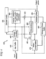
- Turning to
FIG. 1 , a conventional quantization parameter encoding process in a video encoder is indicated generally by thereference numeral 100. Themethod 100 includes astart block 105 that passes control to afunction block 110. Thefunction block 110 sets a quantization parameter (QP) for a slice to SliceQPy, stores SliceQPy as the QP predictor, and passes control to aloop limit block 115. Theloop limit block 115 begins a loop using a variable i having a range from 1, ..., number (#) of coding units, and passes control to afunction block 120. Thefunction block 120 sets the QP for each coding unit to QPcu, and passes control to afunction block 125. Thefunction block 125 encodes delta_QP = QPcu - SliceQPy, and passes control to afunction block 130. Thefunction block 130 encodes coding unit i, and passes control to aloop limit block 135. Theloop limit block 135 ends the loop over the coding units, and passes control to anend block 199. - Thus, in
method 100, a single QP, namely the slice QP (SliceQPy), is used as the predictor for the QP to be encoded. Regardingfunction block 120, the QP for a coding unit is adjusted based on its content and/or the previous encoding results. For example, a smooth coding unit will lower the QP to improve the perceptual quality. In another example, if the previous coding units use more bits than the assigned ones, then the current coding unit will increase the QP to consume fewer bits than what is originally assigned. The difference between the QP for the current coding unit (QPcu) and the QP predictor, SliceQPy, in this example, is encoded (per function block 125). - Turning to
FIG. 2 , a conventional quantization parameter decoding process in a video decoder is indicated generally by thereference numeral 200. Themethod 200 includes astart block 205 that passes control to afunction block 210. Thefunction block 210 decodes SliceQPy, stores SliceQPy as the QP predictor, and passes control to aloop limit block 215. Theloop limit block 215 begins a loop using a variable i having a range from 1, ..., number (#) of coding units, and passes control to afunction block 220. Thefunction block 220 decodes delta_QP, and passes control to afunction block 225. Thefunction block 225 sets the QP for each coding unit to QPcu= SliceQPy + delta_QP, and passes control to afunction block 230. Thefunction block 230 decodes coding unit i, and passes control to aloop limit block 235. Theloop limit block 235 ends the loop over the coding units, and passes control to anend block 299. Regardingfunction block 230, the coding unit is reconstructed thereby. - These and other drawbacks and disadvantages of the prior art are addressed by the present principles, which are directed to methods and apparatus for determining quantization parameter predictors from a plurality of neighboring quantization parameters.
- According to an aspect of the present principles, the present principles relate to a non-transitory computer readable storage media having video signal data encoded thereupon, comprising:
- image data encoded for at least a portion of a picture using a quantization parameter predictor for a current quantization parameter to be applied to the image data, the quantization parameter predictor being determined using multiple quantization parameters from previously coded neighboring portions,
- According to an embodiment the quantization parameter predictor is selected from one or more quantization parameters corresponding to a same portion of the picture as that used for a motion vector prediction, the one or more quantization parameters being among the multiple quantization parameters.
- According to an embodiment, a motion vector competition is used to determine the motion vector predictor.
According to an embodiment, the image data is a transform unit, and the difference between the current quantization parameter and the quantization parameter predictor is only decoded when the transform unit includes non-zero coefficients. - The present principles also relate to a method, comprising:
- decoding image data for at least a portion of a picture using a quantization parameter predictor for a current quantization parameter to be applied to the image data, the quantization parameter predictor being determined using multiple quantization parameters from previously coded neighboring portions; and
- decoding a difference between the current quantization parameter and the quantization parameter predictor for use in decoding the image data, and
- According to an embodiment, the quantization parameter predictor is selected from one or more quantization parameters corresponding to a same portion of the picture as that used for a motion vector prediction, the one or more quantization parameters being among the multiple quantization parameters.
- According to an embodiment, a motion vector competition is used to determine the motion vector predictor.
- According to an embodiment, the image data is a transform unit, and the difference between the current quantization parameter and the quantization parameter predictor is only decoded when the transform unit includes non-zero coefficients.
- These and other aspects, features and advantages of the present principles will become apparent from the following detailed description of exemplary embodiments, which is to be read in connection with the accompanying drawings.
- The present principles may be better understood in accordance with the following exemplary figures, in which:
-
FIG. 1 is a flow diagram showing a conventional quantization parameter encoding process in a video encoder, in accordance with the prior art; -
FIG. 2 is a flow diagram showing a conventional quantization parameter decoding process in a video decoder, in accordance with the prior art; -
FIG. 3 is a block diagram showing an exemplary video encoder to which the present principles may be applied, in accordance with an embodiment of the present principles; -
FIG. 4 is a block diagram showing an exemplary video decoder to which the present principles may be applied, in accordance with an embodiment of the present principles; -
FIG. 5 is a flow diagram showing an exemplary quantization parameter encoding process in a video encoder, in accordance with an embodiment of the present principles; -
FIG. 6 is a flow diagram showing an exemplary quantization parameter decoding process in a video decoder, in accordance with an embodiment of the present principles; -
FIG. 7 is a diagram showing exemplary neighboring coding units, in accordance with an embodiment of the present principles; -
FIG. 8 is a flow diagram showing another exemplary quantization parameter encoding process in a video encoder, in accordance with an embodiment of the present principles; -
FIG. 9 is a flow diagram showing another exemplary quantization parameter decoding process in a video decoder, in accordance with an embodiment of the present principles; -
FIG. 10 is a flow diagram showing yet another exemplary quantization parameter encoding process in a video encoder, in accordance with an embodiment of the present principles, in accordance with an embodiment of the present principles; and -
FIG. 11 is a flow diagram showing yet another exemplary quantization parameter decoding process in a video decoder, in accordance with an embodiment of the present principles. - The present principles are directed to methods and apparatus for determining quantization parameter predictors from a plurality of neighboring quantization parameters.
- The present description illustrates the present principles. It will thus be appreciated that those skilled in the art will be able to devise various arrangements that, although not explicitly described or shown herein, embody the present principles and are included within its spirit and scope.
- All examples and conditional language recited herein are intended for pedagogical purposes to aid the reader in understanding the present principles and the concepts contributed by the inventor(s) to furthering the art, and are to be construed as being without limitation to such specifically recited examples and conditions.
- Moreover, all statements herein reciting principles, aspects, and embodiments of the present principles, as well as specific examples thereof, are intended to encompass both structural and functional equivalents thereof. Additionally, it is intended that such equivalents include both currently known equivalents as well as equivalents developed in the future, i.e., any elements developed that perform the same function, regardless of structure.
- Thus, for example, it will be appreciated by those skilled in the art that the block diagrams presented herein represent conceptual views of illustrative circuitry embodying the present principles. Similarly, it will be appreciated that any flow charts, flow diagrams, state
transition diagrams, pseudocode, and the like represent various processes which may be substantially represented in computer readable media and so executed by a computer or processor, whether or not such computer or processor is explicitly shown. - The functions of the various elements shown in the figures may be provided through the use of dedicated hardware as well as hardware capable of executing software in association with appropriate software. When provided by a processor, the functions may be provided by a single dedicated processor, by a single shared processor, or by a plurality of individual processors, some of which may be shared. Moreover, explicit use of the term "processor" or "controller" should not be construed to refer exclusively to hardware capable of executing software, and may implicitly include, without limitation, digital signal processor ("DSP") hardware, read-only memory ("ROM") for storing software, random access memory ("RAM"), and non-volatile storage.
- Other hardware, conventional and/or custom, may also be included. Similarly, any switches shown in the figures are conceptual only. Their function may be carried out through the operation of program logic, through dedicated logic, through the interaction of program control and dedicated logic, or even manually, the particular technique being selectable by the implementer as more specifically understood from the context.
- In the claims hereof, any element expressed as a means for performing a specified function is intended to encompass any way of performing that function including, for example, a) a combination of circuit elements that performs that function or b) software in any form, including, therefore, firmware, microcode or the like, combined with appropriate circuitry for executing that software to perform the function. The present principles as defined by such claims reside in the fact that the functionalities provided by the various recited means are combined and brought together in the manner which the claims call for. It is thus regarded that any means that can provide those functionalities are equivalent to those shown herein.
- Reference in the specification to "one embodiment" or "an embodiment" of the present principles, as well as other variations thereof, means that a particular feature, structure, characteristic, and so forth described in connection with the embodiment is included in at least one embodiment of the present principles. Thus, the appearances of the phrase "in one embodiment" or "in an embodiment", as well any other variations, appearing in various places throughout the specification are not necessarily all referring to the same embodiment.
- It is to be appreciated that the use of any of the following "/", "and/or", and "at least one of', for example, in the cases of "A/B", "A and/or B" and "at least one of A and B", is intended to encompass the selection of the first listed option (A) only, or the selection of the second listed option (B) only, or the selection of bath options (A and B). As a further example, in the cases of "A, B, and/or C" and "at least one of A, B, and C", such phrasing is intended to encompass the selection of the first listed option (A) only, or the selection of the second listed option (B) only, or the selection of the third listed option (C) only, or the selection of the first and the second listed options (A and B) only, or the selection of the first and third listed options (A and C) only, or the selection of the second and third listed options (B and C) only, or the selection of all three options (A and B and C). This may be extended, as readily apparent by one of ordinary skill in this and related arts, for as many items listed.
- Also, as used herein, the words "picture" and "image" are used interchangeably and refer to a still image or a picture from a video sequence. As is known, a picture may be a frame or a field.
- Moreover, as used herein, the phrase "coding unit" (CU) refers to a basic unit which has a square shape. Although it has a similar role to the macroblock and sub-macroblock in the MPEG-4 AVC Standard, the main difference lies in the fact that the coding unit can have various sizes, with no distinction corresponding to its size. All processing except frame- based loop filtering is performed on a coding unit basis, including intra/inter prediction, transform, quantization and entropy coding.
- Further, as used herein, the phrase "prediction unit" (PU) refers to a basic unit for the prediction mode. It should be noted that the PU is only defined for the last-depth CU and its size is limited to that of the CU. All information related to prediction is signaled on a PU basis.
- Also, as used herein, the phrase "transform unit" (TU) refers to a basic unit for the transform. It should be noted that the size of the transform unit may be larger than that of the prediction unit, which is different from previous video standards, but the transform unit may not exceed the coding unit size. However, the transform unit size is not arbitrary and once a prediction unit structure has been defined for a coding unit, only two transform unit partitions are possible. As a result, the size of the transform unit in the coding unit is determined by the transform_unit_sizeJlag. If the transform_unit_sizeJlag is set to 0, the size of the transform unit is the same as that of the coding unit to which the transform unit belongs. Otherwise, the transform unit size is set as NxN or N/2xN/2 according to the prediction unit splitting.
- Additionally, as used herein, the phrase "skip mode" refers to a prediction mode where the motion information is inferred from the motion vector predictor, and neither motion nor texture information are sent.
- Moreover, it is to be appreciated that for purposes of simplicity and clarity of description, we start with the basics defined by the second prior art approach and define new variables, principles, syntax, and so forth as modifications to the second prior art approach. However, it would be apparent to those skilled in the art that the principles and concepts disclosed and described herein in conjunction with the present invention would be applicable to any new or modified standard or proprietary system - and is in no way tied solely to a modification of the second prior art approach. Neither is it tied to the first prior art approach, the MPEG-4 AVC Standard, or any other approach or standard.
- Turning to
FIG. 3 , an exemplary video encoder to which the present principles may be applied is indicated generally by thereference numeral 300. Thevideo encoder 300 includes aframe ordering buffer 310 having an output in signal communication with a non-inverting input of acombiner 385. An output of thecombiner 385 is connected in signal communication with a first input of a transformer and quantizer (with multiple predictors) 325. An output of the transformer and quantizer (with multiple predictors) 325 is connected in signal communication with a first input of anentropy coder 345 and a first input of an inverse transformer and inverse quantizer (with multiple predictors) 350. An output of theentropy coder 345 is connected in signal communication with a first non-inverting input of acombiner 390. An output of thecombiner 390 is connected in signal communication with a first input of anoutput buffer 335. - A first output of an
encoder controller 305 is connected in signal communication with a second input of theframe ordering buffer 310, a second input of the inverse transformer and inverse quantizer (with multiple predictors) 350, an input of a picture-type decision module 315, a first input of a macroblock-type (MB-type)decision module 320, a second input of anintra prediction module 360, a second input of adeblocking filter 365, a first input of amotion compensator 370, a first input of amotion estimator 375, and a second input of areference picture buffer 380. - A second output of the
encoder controller 305 is connected in signal communication with a first input of a Supplemental Enhancement Information (SEI)inserter 330, a second input of the transformer and quantizer (with multiple predictors) 325, a second input of theentropy coder 345, a second input of theoutput buffer 335, and an input of the Sequence Parameter Set (SPS) and Picture Parameter Set (PPS) inserter340. - An output of the
SEI inserter 330 is connected in signal communication with a second non-inverting input of thecombiner 390. - A first output of the picture-
type decision module 315 is connected in signal communication with a third input of theframe ordering buffer 310. A second output of the picture-type decision module 315 is connected in signal communication with a second input of a macroblock-type decision module 320. - An output of the Sequence Parameter Set (SPS) and Picture Parameter Set (PPS)
inserter 340 is connected in signal communication with a third non-inverting input of thecombiner 390. - An output of the inverse quantizer and inverse transformer (with multiple predictors) 350 is connected in signal communication with a first non-inverting input of a
combiner 319. An output of thecombiner 319 is connected in signal communication with a first input of theintra prediction module 360 and a first input of thedeblocking filter 365. An output of thedeblocking filter 365 is connected in signal communication with a first input of areference picture buffer 380. An output of thereference picture buffer 380 is connected in signal communication with a second input of themotion estimator 375 and a third input of themotion compensator 370. A first output of themotion estimator 375 is connected in signal communication with a second input of themotion compensator 370. A second output of themotion estimator 375 is connected in signal communication with a third input of theentropy coder 345. - An output of the
motion compensator 370 is connected in signal communication with a first input of aswitch 397. An output of theintra prediction module 360 is connected in signal communication with a second input of theswitch 397. An output of the macroblock-type decision module 320 is connected in signal communication with a third input of theswitch 397. The third input of theswitch 397 determines whether or not the "data" input of the switch (as compared to the control input, i.e., the third input) is to be provided by themotion compensator 370 or theintra prediction module 360. The output of theswitch 397 is connected in signal communication with a second non-inverting input of thecombiner 319 and an inverting input of thecombiner 385. - A first input of the
frame ordering buffer 310 and an input of theencoder controller 305 are available as inputs of theencoder 100, for receiving an input picture. Moreover, a second input of the Supplemental Enhancement Information (SEI)inserter 330 is available as an input of theencoder 300, for receiving metadata. An output of theoutput buffer 335 is available as an output of theencoder 300, for outputting a bitstream. - Tuming to
FIG. 4 , an exemplary video decoder to which the present principles may be applied is indicated generally by thereference numeral 400. Thevideo decoder 400 includes aninput buffer 410 having an output connected in signal communication with a first input of anentropy decoder 445. A first output of theentropy decoder 445 is connected in signal communication with a first input of an inverse transformer and inverse quantizer (with multiple predictors) 450. An output of the inverse transformer and inverse quantizer (with multiple predictors) 450 is connected in signal communication with a second non-inverting input of acombiner 425. An output of thecombiner 425 is connected in signal communication with a second input of adeblocking filter 465 and a first input of anintra prediction module 460. A second output of thedeblocking filter 465 is connected in signal communication with a first input of areference picture buffer 480. An output of thereference picture buffer 480 is connected in signal communication with a second input of a motion compensator470. - A second output of the
entropy decoder 445 is connected in signal communication with a third input of themotion compensator 470, a first input of thedeblocking filter 465, and a third input of theintra predictor 460. A third output of theentropy decoder 445 is connected in signal communication with an input of adecoder controller 405. A first output of thedecoder controller 405 is connected in signal communication with a second input of theentropy decoder 445. A second output of thedecoder controller 405 is connected in signal communication with a second input of the inverse transformer and inverse quantizer (with multiple predictors) 450. A third output of thedecoder controller 405 is connected in signal communication with a third input of thedeblocking filter 465. A fourth output of thedecoder controller 405 is connected in signal communication with a second input of theintra prediction module 460, a first input of themotion compensator 470, and a second input of thereference picture buffer 480. - An output of the
motion compensator 470 is connected in signal communication with a first input of aswitch 497. An output of theintra prediction module 460 is connected in signal communication with a second input of theswitch 497. An output of theswitch 497 is connected in signal communication with a first non-inverting input of thecombiner 425. - An input of the
input buffer 410 is available as an input of thedecoder 400, for receiving an input bitstream. A first output of thedeblocking filter 465 is available as an output of thedecoder 400, for outputting an output picture. - As noted above, the present principles are directed to methods and apparatus for determining quantization parameter predictors from a plurality of neighboring quantization parameters.
- Regarding the aforementioned first and second prior art approaches, we note that the same support adjusting quantization parameters on a block level, where the block can be a macroblock, a large block (as in the first prior art approach), or a coding unit (as in the second prior art approach). The quantization parameter values are differentially coded. In the MPEG-4 AVC Standard and in the first prior art approach, the quantization parameter of the previous block in the coding order in the current slice is used as the predictor. In the second prior art approach, the slice quantization parameter is used as the predictor.
- In accordance with the present principles, we provide methods and apparatus for determining the quantization parameter predictor using multiple quantization parameters of the neighboring coded blocks. The quantization parameter predictor calculation is defined by a rule, which is known to both the encoder and decoder. One benefit of this scheme over prior schemes is the reduction of overhead needed for signaling quantization parameters to the decoder.
- The quantization parameter is often adjusted to meet the target bit rate or adapt to the content to improve the visual quality. This causes QP variations among the coding units.
- For purposes of description of the present principles, the word coding unit(s) is meant to include a broad spectrum of image partitions and regions including, but not limited to blocks, macroblocks, superblocks, supermacroblocks, submacroblocks, sub blocks, image partitions, image geometric partitions, image regions, prediction unit, and transform unit. To reduce the overhead cost in signaling the QP difference, we disclose and describe methods and apparatus to improve the QP predictor performance. The QP predictor is formed by multiple QPs from neighboring blocks of previously encoded/decoded coding units, using the same method at both the encoder and decoder, thereby reducing the signaling overhead required.
- Turning to
FIG. 5 , an exemplary quantization parameter encoding process in a video encoder is indicated generally by thereference numeral 500. Themethod 500 includes astart block 505 that passes control to aloop limit block 510. Theloop limit block 510 begins a loop using a variable i having a range from 1, ..., number (#) of coding units, and passes control to afunction block 515. Thefunction block 515 forms a QP predictor (QPPREo) using multiple QPs of previously encoded coding units, and passes control to afunction block 520. Thefunction block 520 sets the QP for each coding unit to QPcu, and passes control to afunction block 525. Thefunction block 525 encodes delta_QP = QPcu - QPPRED, and passes control to afunction block 530. Thefunction block 530 encodes coding unit i, and passes control to aloop limit block 535. Theloop limit block 535 ends the loop over the coding units, and passes control to anend block 599. Regardingfunction block 515, the same coding units used for motion vector prediction can be used to form the predictor QPPRED· For example, the coding units used to form the median motion vector in the MPEG-4 AVC Standard, or the coding unit used in a motion vector competition can be used. - Turning to
FIG. 6 , an exemplary quantization parameter decoding process in a video decoder is indicated generally by thereference numeral 600. Themethod 600 includes astart block 605 that passes control to aloop limit block 610. Theloop limit block 610 begins a loop using a variable i having a range from 1, ... , number (#) of coding units, and passes control to afunction block 615. Thefunction block 615 forms a QP predictor (QPPREo) using multiple QPs of previously decoded coding units, and passes control to afunction block 620. Thefunction block 620 decodes delta_QP, and passes control to afunction block 625. Thefunction block 625 sets the QP for each coding unit to QPcu = delta_QP + QPPRED, and passes control to afunction block 630. Thefunction block 630 decodes coding unit i, and passes control to aloop limit block 635. Theloop limit block 635 ends the loop over the coding units, and passes control to anend block 699. Regardingfunction block 615, the same coding units used for motion vector prediction can be used to form the predictor QPPRED· For example, the coding units used to form the median motion vector in the MPEG-4 AVC Standard, or the coding unit used in a motion vector competition can be used. - In the following, we disclose and describe a scheme to form the QP predictor. The same methodology is used at both the encoder and decoder for synchrony.
- Providing high perceptual quality at the region of interest has a pronounced impact in the overall perceptual quality. Hence a general guideline in the QP adjustment is to assign lower QPs to the regions of interest to improve the perceptual quality and higher QPs to other areas to reduce the number of bits. Since the picture content has great continuity, the QPs for neighboring coding units are often correlated. In the prior art, the correlation between the current QP and the QP of the previously coded block is exploited. Since the QP can also correlate to QPs from other neighboring blocks, we improve the QP predictor by considering more QPs. Turning to
FIG. 7 , exemplary neighboring coding units are indicated generally by thereference numeral 700. The neighboringcoding units 700 include the following: left neighboring coding unit indicated by A; top neighboring coding unit indicated by B; top-right neighboring coding unit indicated by C; and top-left neighboring coding unit indicated by D). Neighboring coding units A through D are used to form a QP predictor for the current coding unit indicated by E. In one example, the definitions of A, B, C, and D are the same as the blocks used for the MPEG-4 AVC Standard motion vector predictors. More QPs from other neighboring coding units can also be included to obtain the QP predictor. - The QP predictor will be formed according to a rule that is known to both the encoder and decoder. Using the QP at coding unit A, B, and C, we provide a few exemplary rules as follows:
- Rule 1: QPPRED = median(QPA, QPB, QPc);
- Rule2:QPPRED=min(QPA,QPB,QPc);
- Rule3:QPPRED=max(QPA,QPB,QPc);
- Rule 4: QPPRED = mean(QPA, QPB, QPc) or QPPRED = mean(QPA, QPB);
- If not all the coding units (A, B, C) are available, we can replace their QPs with the SliceQPy, or only use the available QPs to form the predictor. For example, when coding unit A is unavailable, Rule 2 becomes QPPRED =min(QPB, QPc). In another example, when not all coding units are available, we can replace the missing QPs with QPs of other blocks, for example using block D to replace block C.
- Motion vector prediction in the MPEG-4 AVC Standard shares a similar philosophy of generating the motion vector predictor using the median vector of its neighboring motion vectors. The difference between the motion vector and the motion vector predictor is encoded and sent in the bitstream. To unify the prediction processes for both motion vector and QP, one embodiment is to use the same neighboring coding units to predict both the motion vector and QP when a block is coded in the INTER mode.
- The VCEG "key technical area" (KTA) software (KTA software Version KTA2.6) has provided a common platform to integrate the new advances in video coding after the MPEG-4 AVC Standard is finalized. The proposa! of using a motion vector competition was adopted into KTA. In the motion vector competition scheme, a coding block has a set of motion vector predictor candidates that include motion vectors of spatially or temporally neighboring blocks. The best motion vector predictor is selected from the candidate set based on rate-distortion optimization. The index of the motion vector predictor in the set is explicitly transmitted to the decoder if the set has more than one candidate. To unify the prediction processes for both motion vector and QP, one embodiment involves using the same neighboring coding units to predict bath the motion vector and QP when a black is coded in the INTER mode. Since the index of the motion vector predictor is already sent for the motion vector competition, no extra overhead is necessary for the QP predictor.
- The coding unit can be as large as 128x128. This translates into very few coding units in a picture. To meet the target bit rate accurately, the QP variation between the coding units may be large. One solution to smooth the QP variation is to apply the QP adjustment at the prediction unit instead of the coding unit. We only need to send the QP difference when the prediction unit is not in askip mode.
- Turning to
FIG. 8 , another exemplary quantization parameter encoding process in a video encoder is indicated generally by thereference numeral 800. It is to be appreciated that themethod 800 involves QP adjustment at the prediction unit. Themethod 800 includes a start black 805 that passes control to a loop limit black 810. The loop limit black 810 begins a loop using a variable i having a range from 1, ..., number (#) of prediction units, and passes control to afunction black 815. The function black 815 forms a QP predictor (QPPREo) using multiple QPs of previously encoded prediction units, and passes control to afunction black 820. The function black 820 sets the QP for each prediction unit to QPpu, and passes control to afunction black 825. The function black 825 encodes delta_QP = QPpu -QPPRED, and passes control to afunction black 830. The function black 830 encodes prediction unit i if prediction unit i is not in a skip mode, and passes control to a loop limit black 835. The loop limit black 835 ends the loop over the prediction units, and passes control to anend black 899. Regarding function black 815, the same prediction units used for motion vector prediction can be used to form the predictor QPPRED· For example, the prediction units used to form the median motion vector in the MPEG-4 AVC Standard, or the prediction unit used in a motion vector competition can be used. - Turning to
FIG. 9 , another exemplary quantization parameter decoding process in a video decoder is indicated generally by thereference numeral 900. It is to be appreciated that themethod 900 involves QP adjustment at the prediction unit. Themethod 900 includes a start black 905 that passes control to a loop limit black 910. The loop limit black 910 begins a loop using a variable i having a range from 1, ..., number (#) of prediction units, and passes control to afunction black 915. The function black 915 forms a QP predictor (QPPREo) using multiple QPs of previously decoded prediction units, and passes control to afunction black 920. The function black 920 decodes delta_QP, and passes control to afunction block 925. Thefunction block 925 sets the QP for each prediction unit to QPpu = delta_QP + QPPRED, and passes control to afunction block 930. Thefunction block 930 decodes prediction unit i if prediction unit i is not in a skip mode, and passes control to aloop limit block 935. Theloop limit block 935 ends the loop over the prediction units, and passes control to anend block 999. Regardingfunction block 915, the same prediction units used for motion vector prediction can be used to form the predictor QPPRED· For example, the prediction units used to form the median motion vector in the MPEG-4 AVC Standard, or the prediction unit used in a motion vector competition can be used. - Similarly to
variation 1, we can apply the QP adjustment at the transform unit. We only need to send the QP difference when there are non-zero transform coefficients in the transform unit. - Turning to
FIG. 10 , yet another exemplary quantization parameter encoding process in a video encoder is indicated generally by thereference numeral 1000. It is to be appreciated that themethod 1000 involves QP adjustment at the transform unit. Themethod 1000 includes astart block 1005 that passes control to aloop limit block 1010. Theloop limit block 1010 begins a loop using a variable i having a range from 1, ..., number (#) of transform units, and passes control to afunction block 1015. Thefunction block 1015 forms a QP predictor (QPPREo) using multiple QPs of previously encoded transform units, and passes control to afunction block 1020. Thefunction block 1020 sets the QP for each transform unit to QPru, and passes control to afunction block 1025. Thefunction block 1025 encodes delta_QP = QPru - QPPRED, and passes control to afunction block 1030. Thefunction block 1030 encodes transform unit i if transform unit i has non-zero coefficients, and passes control to aloop limit block 1035. Theloop limit block 1035 ends the loop over the transform units, and passes control to anend block 1099. Regardingfunction block 1015, the same transform units used for motion vector prediction can be used to form the predictor QPPRED· For example, the transform units used to form the median motion vector in the MPEG-4 AVC Standard, or the transform unit used in a motion vector competition can be used. - Turning to
FIG. 11 , yet another exemplary quantization parameter decoding process in a video decoder is indicated generally by thereference numeral 1100. It is to be appreciated that themethod 1100 involves QP adjustment at the transform unit. Themethod 1100 includes astart block 1105 that passes control to aloop limit block 1110. Theloop limit block 1110 begins a loop using a variable i having a range from 1, ... , number (#) of transform units, and passes control to afunction block 1115.Tue function block 1115 forms a QP predictor (QPPREo) using multiple QPs of previously decoded transform units, and passes control to afunction block 1120. Thefunction block 1120 decodes delta_QP, and passes control to afunction block 1125. Thefunction block 1125 sets the QP for each transform unit to QPru = delta_QP+ QPPRED, and passes control to afunction block 1130.Tue function block 1130 decodes transform unit i if transform unit i has non-zero coefficients, and passes control to aloop limit block 1135. Tueloop limit block 1135 ends the loop over the transform units, and passes control to anend block 1199. Regardingfunction block 1115, the same transform units used for motion vector prediction can be used to form the predictor QPPRED· For example, the transform units used to form the median motion vector in the MPEG-4 AVC Standard, or the transform unit used in a motion vector competition can be used. - Using the QP adjustment at the transform unit as an example, we describe how to design the syntax to apply to the present principles. A syntax element TU_delta_QP is used to specify the QP difference between the QP for the current transform unit and the QP predictor. The QP difference can also be specified at the prediction unit or coding unit. TABLE 1 shows exemplary syntax in a transform unit, in accordance with an embodiment of the present principles.

- The semantics of a syntax element TU_delta_QP shown in TABLE 1 is as follows:
- TU_delta_QP specifies the value of the QP difference between the QP for the current transform unit (QPru) and the QP predictor (QPPREo), The QP for the transform unit (QPru) is derived as QPru = QPPRED + TU_delta_QP. TU_delta_QP is only needed when there are non-zero coefficients in the transform unit (i.e., code_block_flag is not zero).
- A description will now be given of some of the many attendant advantages/features of the present invention, some of which have been mentioned above. For example, one advantage/feature is an apparatus having a encoder for encoding image data for at least a portion of a picture using a quantization parameter predictor for a current quantization parameter to be applied to the image data, the quantization parameter predictor being determined using multiple quantization parameters from previously coded neighboring portions, wherein a difference between the current quantization parameter and the quantization parameter predictor is encoded for signaling to a corresponding decoder.
- Another advantage/feature is the apparatus having the encoder as described above, wherein the quantization parameter predictor is implicitly derived based on a rule that is known to both the encoder and the decoder.
- Yet another advantage/feature is the apparatus having the encoder wherein the quantization parameter predictor is implicitly derived based on a rule that is known to both the encoder and the decoder as described above, wherein the rule is for at least one of determining and selecting the quantization parameter predictor responsive to at least one of a quantization parameter having a minimum value from among the multiple quantization parameters, a quantization parameter having a maximum value from among the multiple quantization parameters, a quantization parameter calculated from a median value of at least some of the multiple quantization parameters, and a quantization parameter calculated from a mean value of at least some of the multiple quantization parameters.
- Still another advantage/feature is the apparatus having the encoder as described above, wherein the quantization parameter predictor is selected from one or more quantization parameters corresponding to a same portion of the picture as that used for a motion vector prediction, the one or more quantization parameters being among the multiple quantization parameters.
- Moreover, another advantage/feature is the apparatus having the encoder wherein the quantization parameter predictor is selected from one or more quantization parameters corresponding to a same portion of the picture as that used for a motion vector prediction, the one or more quantization parameters being among the multiple quantization parameters as described above, wherein a motion vector competition is used to determine the motion vector predictor.
- Further, another advantage/feature is the apparatus having the encoder as described above, wherein the image data is one of a coding unit, a prediction unit, and a transform unit.
- Also, another advantage/feature is the apparatus having the encoder wherein the image data is one of a coding unit, a prediction unit, and a transform unit as described above, wherein the image data is the prediction unit, and the difference between the current quantization parameter and the quantization parameter predictor is only encoded for signaling to the corresponding decoder when the prediction unit is in a non-skip mode.
- Additionally, another advantage/feature is the apparatus having the encoder as described above, wherein the image data is the transform unit, and the difference between the current quantization parameter and the quantization parameter predictor is only encoded for signaling to the corresponding decoder when the transform unit includes non-zero coefficients.
- These and other features and advantages of the present principles may be readily ascertained by one of ordinary skill in the pertinent art based on the teachings herein. It is to be understood that the teachings of the present principles may be implemented in various forms of hardware, software, firmware, special purpose processors, or combinations thereof.
- Most preferably, the teachings of the present principles are implemented as a combination of hardware and software. Moreover, the software may be implemented as an application program tangibly embodied on a program storage unit. The application program may be uploaded to, and executed by, a machine comprising any suitable architecture. Preferably, the machine is implemented on a computer platform having hardware such as one or more central processing units ("CPU"), a random access memory ("RAM"), and input/output ("VO") interfaces. The computer platform may also include an operating system and microinstruction code. The various processes and functions described herein may be either part of the microinstruction code or part of the application program, or any combination thereof, which may be executed by a CPU. In addition, various other peripheral units may be connected to the computer platform such as an additional data storage unit and a printing unit.
- It is to be further understood that, because some of the constituent system components and methods depicted in the accompanying drawings are preferably implemented in software, the actual connections between the system components or the process function blocks may differ depending upon the manner in which the present principles are programmed. Given the teachings herein, one of ordinary skill in the pertinent art will be able to contemplate these and similar implementations or configurations of the present principles.
- Although the illustrative embodiments have been described herein with reference to the accompanying drawings, it is to be understood that the present principles is not limited to those precise embodiments, and that various changes and modifications may be effected therein by one of ordinary skill in the pertinent art without departing from the scope or spirit of the present principles. All such changes and modifications are intended to be included within the scope of the present principles as set forth in the appended claims.
wherein said quantization parameter predictor is determined by finding a mean of the quantization parameters of the previously coded neighboring portion to the left and the previously coded neighboring portion above the portion currently being encoded when these neighboring portions are available, and
if at least one of said neighboring portions is not available, basing the quantization parameter predictor on a quantization parameter for a current slice.
if at least one of said neighboring portions is not available, basing the quantization parameter predictor on a quantization parameter for a current slice.
Claims (8)
- A non-transitory computer readable storage media having video signal data encoded thereupon, comprising:- image data encoded for at least a portion of a picture using a quantization parameter predictor for a current quantization parameter to be applied to the image data, the quantization parameter predictor being determined using multiple quantization parameters from previously coded neighboring portions,wherein a difference between the current quantization parameter and the quantization parameter predictor is encoded for signaling to a corresponding decoder, and
wherein said quantization parameter predictor is determined by finding a mean of the quantization parameters of the previously coded neighboring portion to the left and the previously coded neighboring portion above the portion currently being encoded when these neighboring portions are available, and
if at least one of said neighboring portions is not available, basing the quantization parameter predictor on a quantization parameter for a current slice. - The non-transitory computer readable storage media of claim 1, wherein the quantization parameter predictor is selected from one or more quantization parameters corresponding to a same portion of the picture as that used for a motion vector prediction, the one or more quantization parameters being among the multiple quantization parameters.
- The non-transitory computer readable storage media of claim 2, wherein a motion vector competition is used to determine the motion vector predictor.
- The non-transitory computer readable storage media of claim 1, wherein the image data is a transform unit, and the difference between the current quantization parameter and the quantization parameter predictor is only decoded when the transform unit includes non-zero coefficients.
- In a video decoder, a method, comprising:- decoding image data for at least a portion of a picture using a quantization parameter predictor for a current quantization parameter to be applied to the image data, the quantization parameter predictor being determined using multiple quantization parameters from previously coded neighboring portions; and- decoding a difference between the current quantization parameter and the quantization parameter predictor for use in decoding the image data, andwherein said quantization parameter predictor is determined by finding a mean of the quantization parameters of the previously coded neighboring portion to the left and the previously coded neighboring portion above the portion currently being decoded when these neighboring portions are available, and
if at least one of said neighboring portions is not available, basing the quantization parameter predictor on a quantization parameter for a current slice. - The method of claim 5, wherein the quantization parameter predictor is selected from one or more quantization parameters corresponding to a same portion of the picture as that used for a motion vector prediction, the one or more quantization parameters being among the multiple quantization parameters.
- The method of claim 6, wherein a motion vector competition is used to determine the motion vector predictor.
- The method of claim 5, wherein the image data is a transform unit, and the difference between the current quantization parameter and the quantization parameter predictor is only decoded when the transform unit includes non-zero coefficients.
Priority Applications (1)
| Application Number | Priority Date | Filing Date | Title |
|---|---|---|---|
| PL17182141T PL3267684T3 (en) | 2010-06-10 | 2011-06-08 | Method for determining quantization parameter predictors from a plurality of neighboring quantization parameters |
Applications Claiming Priority (3)
| Application Number | Priority Date | Filing Date | Title |
|---|---|---|---|
| US35336510P | 2010-06-10 | 2010-06-10 | |
| PCT/US2011/039579 WO2011156458A1 (en) | 2010-06-10 | 2011-06-08 | Methods and apparatus for determining quantization parameter predictors from a plurality of neighboring quantization parameters |
| EP11727593.3A EP2580911A1 (en) | 2010-06-10 | 2011-06-08 | Methods and apparatus for determining quantization parameter predictors from a plurality of neighboring quantization parameters |
Related Parent Applications (1)
| Application Number | Title | Priority Date | Filing Date |
|---|---|---|---|
| EP11727593.3A Division EP2580911A1 (en) | 2010-06-10 | 2011-06-08 | Methods and apparatus for determining quantization parameter predictors from a plurality of neighboring quantization parameters |
Publications (2)
| Publication Number | Publication Date |
|---|---|
| EP3267684A1 true EP3267684A1 (en) | 2018-01-10 |
| EP3267684B1 EP3267684B1 (en) | 2021-09-22 |
Family
ID=44351363
Family Applications (4)
| Application Number | Title | Priority Date | Filing Date |
|---|---|---|---|
| EP11727593.3A Ceased EP2580911A1 (en) | 2010-06-10 | 2011-06-08 | Methods and apparatus for determining quantization parameter predictors from a plurality of neighboring quantization parameters |
| EP22155475.1A Active EP4024865B1 (en) | 2010-06-10 | 2011-06-08 | Methods and apparatus for determining quantization parameter predictors from a plurality of neighboring quantization parameters |
| EP23205217.5A Pending EP4287621A3 (en) | 2010-06-10 | 2011-06-08 | Methods and apparatus for determining quantization parameter predictors from a plurality of neighboring quantization parameters |
| EP17182141.6A Active EP3267684B1 (en) | 2010-06-10 | 2011-06-08 | Method for determining quantization parameter predictors from a plurality of neighboring quantization parameters |
Family Applications Before (3)
| Application Number | Title | Priority Date | Filing Date |
|---|---|---|---|
| EP11727593.3A Ceased EP2580911A1 (en) | 2010-06-10 | 2011-06-08 | Methods and apparatus for determining quantization parameter predictors from a plurality of neighboring quantization parameters |
| EP22155475.1A Active EP4024865B1 (en) | 2010-06-10 | 2011-06-08 | Methods and apparatus for determining quantization parameter predictors from a plurality of neighboring quantization parameters |
| EP23205217.5A Pending EP4287621A3 (en) | 2010-06-10 | 2011-06-08 | Methods and apparatus for determining quantization parameter predictors from a plurality of neighboring quantization parameters |
Country Status (14)
| Country | Link |
|---|---|
| US (8) | US9235774B2 (en) |
| EP (4) | EP2580911A1 (en) |
| JP (5) | JP5924823B2 (en) |
| KR (6) | KR101822214B1 (en) |
| CN (2) | CN103155553B (en) |
| AU (1) | AU2011264896B2 (en) |
| BR (1) | BR112012031160B1 (en) |
| CA (1) | CA2801409C (en) |
| MX (4) | MX339232B (en) |
| MY (3) | MY162191A (en) |
| PL (1) | PL3267684T3 (en) |
| RU (1) | RU2597510C2 (en) |
| WO (1) | WO2011156458A1 (en) |
| ZA (3) | ZA201209077B (en) |
Cited By (2)
| Publication number | Priority date | Publication date | Assignee | Title |
|---|---|---|---|---|
| WO2019204083A1 (en) * | 2018-04-16 | 2019-10-24 | Interdigital Vc Holdings, Inc. | Quantization parameter prediction for video encoding and decoding |
| EP3618440A1 (en) * | 2018-09-03 | 2020-03-04 | InterDigital VC Holdings, Inc. | Quantization parameter prediction for video encoding and decoding |
Families Citing this family (41)
| Publication number | Priority date | Publication date | Assignee | Title |
|---|---|---|---|---|
| KR101822214B1 (en) | 2010-06-10 | 2018-01-25 | 톰슨 라이센싱 | Methods and apparatus for determining quantization parameter predictors from a plurality of neighboring quantization parameters |
| KR20120016980A (en) * | 2010-08-17 | 2012-02-27 | 한국전자통신연구원 | Image encoding and decoding method and the same apparatus |
| US20120189052A1 (en) * | 2011-01-24 | 2012-07-26 | Qualcomm Incorporated | Signaling quantization parameter changes for coded units in high efficiency video coding (hevc) |
| JP6056122B2 (en) * | 2011-01-24 | 2017-01-11 | ソニー株式会社 | Image encoding apparatus, image decoding apparatus, method and program thereof |
| JP2017079485A (en) * | 2011-01-24 | 2017-04-27 | ソニー株式会社 | Image encoder, image encoding method and program |
| EP2863637B1 (en) | 2011-03-09 | 2018-12-12 | Nec Corporation | Video decoding device, video decoding method and video decoding program |
| KR102032940B1 (en) | 2011-03-11 | 2019-10-16 | 소니 주식회사 | Image processing device, image processing method and computer readable recording medium |
| US10298939B2 (en) | 2011-06-22 | 2019-05-21 | Qualcomm Incorporated | Quantization in video coding |
| KR20130049522A (en) * | 2011-11-04 | 2013-05-14 | 오수미 | Method for generating intra prediction block |
| US9571833B2 (en) | 2011-11-04 | 2017-02-14 | Nokia Technologies Oy | Method for coding and an apparatus |
| KR20130049523A (en) * | 2011-11-04 | 2013-05-14 | 오수미 | Apparatus for generating intra prediction block |
| KR20130050404A (en) | 2011-11-07 | 2013-05-16 | 오수미 | Method for generating reconstructed block in inter prediction mode |
| KR20130050403A (en) * | 2011-11-07 | 2013-05-16 | 오수미 | Method for generating rrconstructed block in inter prediction mode |
| US9088796B2 (en) * | 2011-11-07 | 2015-07-21 | Sharp Kabushiki Kaisha | Video decoder with enhanced CABAC decoding |
| KR20130050405A (en) | 2011-11-07 | 2013-05-16 | 오수미 | Method for determining temporal candidate in inter prediction mode |
| KR20130050406A (en) * | 2011-11-07 | 2013-05-16 | 오수미 | Method for generating prediction block in inter prediction mode |
| US20130114686A1 (en) * | 2011-11-08 | 2013-05-09 | Sharp Laboratories Of America, Inc. | Video decoder with enhanced cabac motion vector decoding |
| JP6064581B2 (en) * | 2011-12-21 | 2017-01-25 | 株式会社Jvcケンウッド | Moving picture decoding apparatus, moving picture decoding method, moving picture decoding program, receiving apparatus, receiving method, and receiving program |
| JP6064580B2 (en) * | 2011-12-21 | 2017-01-25 | 株式会社Jvcケンウッド | Moving picture encoding apparatus, moving picture encoding method, moving picture encoding program, transmission apparatus, transmission method, and transmission program |
| AR092786A1 (en) * | 2012-01-09 | 2015-05-06 | Jang Min | METHODS TO ELIMINATE BLOCK ARTIFACTS |
| EP4002840A1 (en) * | 2012-01-17 | 2022-05-25 | Innotive Ltd | Apparatus for applying edge offset |
| CA2863390C (en) * | 2012-01-30 | 2019-01-15 | Samsung Electronics Co., Ltd. | Method and apparatus for hierarchical data unit-based video encoding and decoding comprising quantization parameter prediction |
| WO2013145642A1 (en) * | 2012-03-28 | 2013-10-03 | 株式会社Jvcケンウッド | Image encoding device, image encoding method, image encoding program, transmission device, transmission method, transmission program, image decoding device, image decoding method, image decoding program, reception device, reception method, and reception program |
| JP5664584B2 (en) * | 2012-03-28 | 2015-02-04 | 株式会社Jvcケンウッド | Image decoding apparatus, image decoding method, image decoding program, receiving apparatus, receiving method, and receiving program |
| US20140079135A1 (en) * | 2012-09-14 | 2014-03-20 | Qualcomm Incoporated | Performing quantization to facilitate deblocking filtering |
| US20140254659A1 (en) | 2013-03-11 | 2014-09-11 | Mediatek Inc. | Video coding method using at least evaluated visual quality and related video coding apparatus |
| JP6373033B2 (en) * | 2014-03-28 | 2018-08-15 | キヤノン株式会社 | Encoding apparatus and encoding method |
| US10136141B2 (en) * | 2014-06-11 | 2018-11-20 | Qualcomm Incorporated | Determining quantization parameter (QP) values and delta QP values for palette coded blocks in video coding |
| US9924175B2 (en) | 2014-06-11 | 2018-03-20 | Qualcomm Incorporated | Determining application of deblocking filtering to palette coded blocks in video coding |
| KR102212762B1 (en) | 2014-09-17 | 2021-02-05 | 삼성전자주식회사 | Codec and devices including the same |
| KR102503900B1 (en) * | 2015-10-05 | 2023-02-27 | 삼성전자주식회사 | Encoder for determining quantization parameter adaptively and application processor having the same |
| JP6876822B2 (en) | 2017-03-21 | 2021-05-26 | ドルビー ラボラトリーズ ライセンシング コーポレイション | Quantization parameter prediction using luminance information |
| JP6311821B2 (en) * | 2017-04-18 | 2018-04-18 | 富士通株式会社 | Moving image processing apparatus and moving image processing method |
| JPWO2019003993A1 (en) * | 2017-06-26 | 2019-12-26 | パナソニック インテレクチュアル プロパティ コーポレーション オブ アメリカPanasonic Intellectual Property Corporation of America | Encoding device, decoding device, encoding method and decoding method |
| WO2019194147A1 (en) * | 2018-04-02 | 2019-10-10 | Sharp Kabushiki Kaisha | Systems and methods for deriving quantization parameters for video blocks in video coding |
| CN109688409B (en) * | 2018-12-28 | 2021-03-02 | 北京奇艺世纪科技有限公司 | Video coding method and device |
| US20220191531A1 (en) * | 2019-03-12 | 2022-06-16 | Hyudai Motor Campany | Method and apparatus for efficiently coding residual blocks |
| CN112004083B (en) * | 2019-05-27 | 2022-04-01 | 北京君正集成电路股份有限公司 | Method and system for optimizing code rate control by utilizing inter-frame prediction characteristics |
| GB2623449A (en) * | 2019-07-05 | 2024-04-17 | V Nova Int Ltd | Quantization of residuals in video coding |
| US20230283768A1 (en) * | 2020-08-04 | 2023-09-07 | Hyundai Motor Company | Method for predicting quantization parameter used in a video encoding/decoding apparatus |
| WO2024005659A1 (en) * | 2022-06-30 | 2024-01-04 | Huawei Technologies Co., Ltd. | Adaptive selection of entropy coding parameters |
Citations (4)
| Publication number | Priority date | Publication date | Assignee | Title |
|---|---|---|---|---|
| EP1995967A1 (en) * | 2006-03-16 | 2008-11-26 | Huawei Technologies Co., Ltd. | Method and apparatus for realizing adaptive quantization in encoding process |
| WO2009105732A1 (en) * | 2008-02-22 | 2009-08-27 | Qualcomm Incorporated | Fast macroblock delta qp decision |
| EP2129134A1 (en) * | 2007-03-20 | 2009-12-02 | Fujitsu Limited | Time-varying image encoding method and device, and time-varying image decoding device |
| US20090296808A1 (en) * | 2008-06-03 | 2009-12-03 | Microsoft Corporation | Adaptive quantization for enhancement layer video coding |
Family Cites Families (24)
| Publication number | Priority date | Publication date | Assignee | Title |
|---|---|---|---|---|
| JPH10336682A (en) * | 1997-04-02 | 1998-12-18 | Canon Inc | Coder, its method and storage medium storing the method |
| PT1978747E (en) | 2001-11-29 | 2014-07-24 | Panasonic Ip Corp America | Coding distortion removal method |
| CN100512441C (en) * | 2001-11-29 | 2009-07-08 | 松下电器产业株式会社 | Coding distortion removal method |
| CN101232618B (en) * | 2002-04-23 | 2013-03-27 | 诺基亚有限公司 | Method and device for indicating quantizer parameters in a video coding system |
| CN101112101A (en) * | 2004-11-29 | 2008-01-23 | 高通股份有限公司 | Rate control techniques for video encoding using parametric equations |
| JP4146444B2 (en) | 2005-03-16 | 2008-09-10 | 株式会社東芝 | Video encoding method and apparatus |
| EP2088784B1 (en) | 2006-11-28 | 2016-07-06 | Panasonic Corporation | Encoding device and encoding method |
| US8577168B2 (en) * | 2006-12-28 | 2013-11-05 | Vidyo, Inc. | System and method for in-loop deblocking in scalable video coding |
| US20080240242A1 (en) | 2007-03-27 | 2008-10-02 | Nokia Corporation | Method and system for motion vector predictions |
| US20100040153A1 (en) | 2007-05-07 | 2010-02-18 | Panasonic Corporation | Decoding apparatus and decoding method |
| JP5007259B2 (en) * | 2008-03-27 | 2012-08-22 | ルネサスエレクトロニクス株式会社 | Image encoding device |
| US8503527B2 (en) | 2008-10-03 | 2013-08-06 | Qualcomm Incorporated | Video coding with large macroblocks |
| CN101897189B (en) | 2008-10-10 | 2016-07-06 | 松下电器产业株式会社 | Picture decoding apparatus and picture decoding method |
| EP2357825A4 (en) | 2008-12-08 | 2012-06-20 | Panasonic Corp | Image decoding apparatus and image decoding method |
| CN101494776B (en) * | 2009-02-13 | 2011-01-05 | 北京邮电大学 | H.264 code rate control method |
| EP3410707A1 (en) | 2009-09-10 | 2018-12-05 | Guangdong OPPO Mobile Telecommunications Corp., Ltd. | Speedup techniques for rate distortion optimized quantization |
| WO2011043793A1 (en) * | 2009-10-05 | 2011-04-14 | Thomson Licensing | Methods and apparatus for embedded quantization parameter adjustment in video encoding and decoding |
| KR101457418B1 (en) * | 2009-10-23 | 2014-11-04 | 삼성전자주식회사 | Method and apparatus for video encoding and decoding dependent on hierarchical structure of coding unit |
| US20110274162A1 (en) | 2010-05-04 | 2011-11-10 | Minhua Zhou | Coding Unit Quantization Parameters in Video Coding |
| WO2011064926A1 (en) | 2009-11-30 | 2011-06-03 | 三菱電機株式会社 | Image coding device, image decoding device, image coding method, and image decoding method |
| US8588297B2 (en) | 2009-12-23 | 2013-11-19 | Oracle America, Inc. | Quantization parameter prediction |
| MX2012013748A (en) | 2010-06-04 | 2013-01-22 | Sony Corp | Image processing device and method. |
| KR101822214B1 (en) | 2010-06-10 | 2018-01-25 | 톰슨 라이센싱 | Methods and apparatus for determining quantization parameter predictors from a plurality of neighboring quantization parameters |
| US20130022108A1 (en) * | 2011-06-30 | 2013-01-24 | General Instrument Corporation | Quantization parameter derivation from qp predictor |
-
2011
- 2011-06-08 KR KR1020137000630A patent/KR101822214B1/en active IP Right Grant
- 2011-06-08 KR KR1020207011212A patent/KR20200043535A/en not_active Application Discontinuation
- 2011-06-08 JP JP2013514328A patent/JP5924823B2/en active Active
- 2011-06-08 MX MX2015000445A patent/MX339232B/en unknown
- 2011-06-08 EP EP11727593.3A patent/EP2580911A1/en not_active Ceased
- 2011-06-08 MY MYPI2012005082A patent/MY162191A/en unknown
- 2011-06-08 BR BR112012031160-3A patent/BR112012031160B1/en active IP Right Grant
- 2011-06-08 CN CN201180039208.9A patent/CN103155553B/en active Active
- 2011-06-08 MX MX2012014478A patent/MX2012014478A/en active IP Right Grant
- 2011-06-08 AU AU2011264896A patent/AU2011264896B2/en active Active
- 2011-06-08 EP EP22155475.1A patent/EP4024865B1/en active Active
- 2011-06-08 EP EP23205217.5A patent/EP4287621A3/en active Pending
- 2011-06-08 RU RU2013100174/08A patent/RU2597510C2/en active
- 2011-06-08 WO PCT/US2011/039579 patent/WO2011156458A1/en active Application Filing
- 2011-06-08 KR KR1020197013710A patent/KR102103967B1/en active IP Right Grant
- 2011-06-08 MY MYPI2015002901A patent/MY176330A/en unknown
- 2011-06-08 CA CA2801409A patent/CA2801409C/en active Active
- 2011-06-08 KR KR1020217013294A patent/KR20210054036A/en not_active IP Right Cessation
- 2011-06-08 PL PL17182141T patent/PL3267684T3/en unknown
- 2011-06-08 KR KR1020227035093A patent/KR20220140875A/en not_active Application Discontinuation
- 2011-06-08 US US13/702,519 patent/US9235774B2/en active Active
- 2011-06-08 MY MYPI2019002645A patent/MY191461A/en unknown
- 2011-06-08 MX MX2016002080A patent/MX355733B/en unknown
- 2011-06-08 KR KR1020187001691A patent/KR101979816B1/en active IP Right Grant
- 2011-06-08 MX MX2016006314A patent/MX353317B/en unknown
- 2011-06-08 CN CN201610907014.0A patent/CN107465924B/en active Active
- 2011-06-08 EP EP17182141.6A patent/EP3267684B1/en active Active
-
2012
- 2012-11-30 ZA ZA2012/09077A patent/ZA201209077B/en unknown
-
2015
- 2015-12-16 US US14/971,394 patent/US9749631B2/en active Active
-
2016
- 2016-03-09 JP JP2016045330A patent/JP6209235B2/en active Active
-
2017
- 2017-07-20 US US15/654,823 patent/US10334247B2/en active Active
- 2017-09-06 JP JP2017170780A patent/JP6630988B2/en active Active
- 2017-11-02 ZA ZA2017/07434A patent/ZA201707434B/en unknown
-
2019
- 2019-03-25 ZA ZA2019/01802A patent/ZA201901802B/en unknown
- 2019-05-10 US US16/408,956 patent/US10547840B2/en active Active
- 2019-11-22 JP JP2019211602A patent/JP7254681B2/en active Active
- 2019-12-19 US US16/720,609 patent/US10742981B2/en active Active
-
2020
- 2020-07-01 US US16/918,069 patent/US11381818B2/en active Active
-
2021
- 2021-09-06 JP JP2021144926A patent/JP7228012B2/en active Active
-
2022
- 2022-06-30 US US17/854,168 patent/US11722669B2/en active Active
-
2023
- 2023-06-13 US US18/208,955 patent/US20230328247A1/en active Pending
Patent Citations (4)
| Publication number | Priority date | Publication date | Assignee | Title |
|---|---|---|---|---|
| EP1995967A1 (en) * | 2006-03-16 | 2008-11-26 | Huawei Technologies Co., Ltd. | Method and apparatus for realizing adaptive quantization in encoding process |
| EP2129134A1 (en) * | 2007-03-20 | 2009-12-02 | Fujitsu Limited | Time-varying image encoding method and device, and time-varying image decoding device |
| WO2009105732A1 (en) * | 2008-02-22 | 2009-08-27 | Qualcomm Incorporated | Fast macroblock delta qp decision |
| US20090296808A1 (en) * | 2008-06-03 | 2009-12-03 | Microsoft Corporation | Adaptive quantization for enhancement layer video coding |
Non-Patent Citations (1)
| Title |
|---|
| LAROCHE G ET AL: "A spatio-temporal competing scheme for the rate-distortion optmized selection and coding of motion vectors", PROCEEDINGS OF THE EUROPEAN SIGNAL PROCESSING CONFERENCE, 4 September 2006 (2006-09-04), pages 1 - 6, XP002439848 * |
Cited By (4)
| Publication number | Priority date | Publication date | Assignee | Title |
|---|---|---|---|---|
| WO2019204083A1 (en) * | 2018-04-16 | 2019-10-24 | Interdigital Vc Holdings, Inc. | Quantization parameter prediction for video encoding and decoding |
| CN112189341A (en) * | 2018-04-16 | 2021-01-05 | 交互数字Vc控股公司 | Quantization parameter prediction for video encoding and decoding |
| US11558615B2 (en) | 2018-04-16 | 2023-01-17 | Interdigital Vc Holdings, Inc. | Quantization parameter prediction for video encoding and decoding |
| EP3618440A1 (en) * | 2018-09-03 | 2020-03-04 | InterDigital VC Holdings, Inc. | Quantization parameter prediction for video encoding and decoding |
Also Published As
Similar Documents
| Publication | Publication Date | Title |
|---|---|---|
| US11722669B2 (en) | Methods and apparatus for determining quantization parameter predictors from a plurality of neighboring quantization parameters | |
| EP2868080B1 (en) | Method and device for encoding or decoding an image | |
| US9819952B2 (en) | Methods and apparatus for embedded quantization parameter adjustment in video encoding and decoding |
Legal Events
| Date | Code | Title | Description |
|---|---|---|---|
| PUAI | Public reference made under article 153(3) epc to a published international application that has entered the european phase |
Free format text: ORIGINAL CODE: 0009012 |
|
| STAA | Information on the status of an ep patent application or granted ep patent |
Free format text: STATUS: THE APPLICATION HAS BEEN PUBLISHED |
|
| AC | Divisional application: reference to earlier application |
Ref document number: 2580911 Country of ref document: EP Kind code of ref document: P |
|
| AK | Designated contracting states |
Kind code of ref document: A1 Designated state(s): AL AT BE BG CH CY CZ DE DK EE ES FI FR GB GR HR HU IE IS IT LI LT LU LV MC MK MT NL NO PL PT RO RS SE SI SK SM TR |
|
| STAA | Information on the status of an ep patent application or granted ep patent |
Free format text: STATUS: REQUEST FOR EXAMINATION WAS MADE |
|
| 17P | Request for examination filed |
Effective date: 20180705 |
|
| RBV | Designated contracting states (corrected) |
Designated state(s): AL AT BE BG CH CY CZ DE DK EE ES FI FR GB GR HR HU IE IS IT LI LT LU LV MC MK MT NL NO PL PT RO RS SE SI SK SM TR |
|
| STAA | Information on the status of an ep patent application or granted ep patent |
Free format text: STATUS: EXAMINATION IS IN PROGRESS |
|
| RAP1 | Party data changed (applicant data changed or rights of an application transferred) |
Owner name: INTERDIGITAL VC HOLDINGS, INC. |
|
| 17Q | First examination report despatched |
Effective date: 20190226 |
|
| RAP1 | Party data changed (applicant data changed or rights of an application transferred) |
Owner name: INTERDIGITAL VC HOLDINGS, INC. |
|
| GRAP | Despatch of communication of intention to grant a patent |
Free format text: ORIGINAL CODE: EPIDOSNIGR1 |
|
| STAA | Information on the status of an ep patent application or granted ep patent |
Free format text: STATUS: GRANT OF PATENT IS INTENDED |
|
| INTG | Intention to grant announced |
Effective date: 20201127 |
|
| GRAJ | Information related to disapproval of communication of intention to grant by the applicant or resumption of examination proceedings by the epo deleted |
Free format text: ORIGINAL CODE: EPIDOSDIGR1 |
|
| STAA | Information on the status of an ep patent application or granted ep patent |
Free format text: STATUS: EXAMINATION IS IN PROGRESS |
|
| INTC | Intention to grant announced (deleted) | ||
| GRAP | Despatch of communication of intention to grant a patent |
Free format text: ORIGINAL CODE: EPIDOSNIGR1 |
|
| STAA | Information on the status of an ep patent application or granted ep patent |
Free format text: STATUS: GRANT OF PATENT IS INTENDED |
|
| INTG | Intention to grant announced |
Effective date: 20210408 |
|
| GRAS | Grant fee paid |
Free format text: ORIGINAL CODE: EPIDOSNIGR3 |
|
| GRAA | (expected) grant |
Free format text: ORIGINAL CODE: 0009210 |
|
| STAA | Information on the status of an ep patent application or granted ep patent |
Free format text: STATUS: THE PATENT HAS BEEN GRANTED |
|
| AC | Divisional application: reference to earlier application |
Ref document number: 2580911 Country of ref document: EP Kind code of ref document: P |
|
| AK | Designated contracting states |
Kind code of ref document: B1 Designated state(s): AL AT BE BG CH CY CZ DE DK EE ES FI FR GB GR HR HU IE IS IT LI LT LU LV MC MK MT NL NO PL PT RO RS SE SI SK SM TR |
|
| REG | Reference to a national code |
Ref country code: GB Ref legal event code: FG4D |
|
| REG | Reference to a national code |
Ref country code: DE Ref legal event code: R096 Ref document number: 602011071844 Country of ref document: DE |
|
| REG | Reference to a national code |
Ref country code: IE Ref legal event code: FG4D |
|
| REG | Reference to a national code |
Ref country code: CH Ref legal event code: EP Ref country code: AT Ref legal event code: REF Ref document number: 1433263 Country of ref document: AT Kind code of ref document: T Effective date: 20211015 |
|
| REG | Reference to a national code |
Ref country code: LT Ref legal event code: MG9D |
|
| REG | Reference to a national code |
Ref country code: NL Ref legal event code: FP |
|
| PG25 | Lapsed in a contracting state [announced via postgrant information from national office to epo] |
Ref country code: SE Free format text: LAPSE BECAUSE OF FAILURE TO SUBMIT A TRANSLATION OF THE DESCRIPTION OR TO PAY THE FEE WITHIN THE PRESCRIBED TIME-LIMIT Effective date: 20210922 Ref country code: RS Free format text: LAPSE BECAUSE OF FAILURE TO SUBMIT A TRANSLATION OF THE DESCRIPTION OR TO PAY THE FEE WITHIN THE PRESCRIBED TIME-LIMIT Effective date: 20210922 Ref country code: LT Free format text: LAPSE BECAUSE OF FAILURE TO SUBMIT A TRANSLATION OF THE DESCRIPTION OR TO PAY THE FEE WITHIN THE PRESCRIBED TIME-LIMIT Effective date: 20210922 Ref country code: BG Free format text: LAPSE BECAUSE OF FAILURE TO SUBMIT A TRANSLATION OF THE DESCRIPTION OR TO PAY THE FEE WITHIN THE PRESCRIBED TIME-LIMIT Effective date: 20211222 Ref country code: HR Free format text: LAPSE BECAUSE OF FAILURE TO SUBMIT A TRANSLATION OF THE DESCRIPTION OR TO PAY THE FEE WITHIN THE PRESCRIBED TIME-LIMIT Effective date: 20210922 Ref country code: FI Free format text: LAPSE BECAUSE OF FAILURE TO SUBMIT A TRANSLATION OF THE DESCRIPTION OR TO PAY THE FEE WITHIN THE PRESCRIBED TIME-LIMIT Effective date: 20210922 |
|
| REG | Reference to a national code |
Ref country code: NO Ref legal event code: T2 Effective date: 20210922 |
|
| REG | Reference to a national code |
Ref country code: AT Ref legal event code: MK05 Ref document number: 1433263 Country of ref document: AT Kind code of ref document: T Effective date: 20210922 |
|
| PG25 | Lapsed in a contracting state [announced via postgrant information from national office to epo] |
Ref country code: LV Free format text: LAPSE BECAUSE OF FAILURE TO SUBMIT A TRANSLATION OF THE DESCRIPTION OR TO PAY THE FEE WITHIN THE PRESCRIBED TIME-LIMIT Effective date: 20210922 Ref country code: GR Free format text: LAPSE BECAUSE OF FAILURE TO SUBMIT A TRANSLATION OF THE DESCRIPTION OR TO PAY THE FEE WITHIN THE PRESCRIBED TIME-LIMIT Effective date: 20211223 |
|
| PG25 | Lapsed in a contracting state [announced via postgrant information from national office to epo] |
Ref country code: AT Free format text: LAPSE BECAUSE OF FAILURE TO SUBMIT A TRANSLATION OF THE DESCRIPTION OR TO PAY THE FEE WITHIN THE PRESCRIBED TIME-LIMIT Effective date: 20210922 |
|
| PG25 | Lapsed in a contracting state [announced via postgrant information from national office to epo] |
Ref country code: IS Free format text: LAPSE BECAUSE OF FAILURE TO SUBMIT A TRANSLATION OF THE DESCRIPTION OR TO PAY THE FEE WITHIN THE PRESCRIBED TIME-LIMIT Effective date: 20220122 Ref country code: SK Free format text: LAPSE BECAUSE OF FAILURE TO SUBMIT A TRANSLATION OF THE DESCRIPTION OR TO PAY THE FEE WITHIN THE PRESCRIBED TIME-LIMIT Effective date: 20210922 Ref country code: RO Free format text: LAPSE BECAUSE OF FAILURE TO SUBMIT A TRANSLATION OF THE DESCRIPTION OR TO PAY THE FEE WITHIN THE PRESCRIBED TIME-LIMIT Effective date: 20210922 Ref country code: PT Free format text: LAPSE BECAUSE OF FAILURE TO SUBMIT A TRANSLATION OF THE DESCRIPTION OR TO PAY THE FEE WITHIN THE PRESCRIBED TIME-LIMIT Effective date: 20220124 Ref country code: ES Free format text: LAPSE BECAUSE OF FAILURE TO SUBMIT A TRANSLATION OF THE DESCRIPTION OR TO PAY THE FEE WITHIN THE PRESCRIBED TIME-LIMIT Effective date: 20210922 Ref country code: EE Free format text: LAPSE BECAUSE OF FAILURE TO SUBMIT A TRANSLATION OF THE DESCRIPTION OR TO PAY THE FEE WITHIN THE PRESCRIBED TIME-LIMIT Effective date: 20210922 Ref country code: CZ Free format text: LAPSE BECAUSE OF FAILURE TO SUBMIT A TRANSLATION OF THE DESCRIPTION OR TO PAY THE FEE WITHIN THE PRESCRIBED TIME-LIMIT Effective date: 20210922 Ref country code: AL Free format text: LAPSE BECAUSE OF FAILURE TO SUBMIT A TRANSLATION OF THE DESCRIPTION OR TO PAY THE FEE WITHIN THE PRESCRIBED TIME-LIMIT Effective date: 20210922 |
|
| REG | Reference to a national code |
Ref country code: FR Ref legal event code: PLFP Year of fee payment: 12 Ref country code: DE Ref legal event code: R097 Ref document number: 602011071844 Country of ref document: DE |
|
| PG25 | Lapsed in a contracting state [announced via postgrant information from national office to epo] |
Ref country code: DK Free format text: LAPSE BECAUSE OF FAILURE TO SUBMIT A TRANSLATION OF THE DESCRIPTION OR TO PAY THE FEE WITHIN THE PRESCRIBED TIME-LIMIT Effective date: 20210922 |
|
| PLBE | No opposition filed within time limit |
Free format text: ORIGINAL CODE: 0009261 |
|
| STAA | Information on the status of an ep patent application or granted ep patent |
Free format text: STATUS: NO OPPOSITION FILED WITHIN TIME LIMIT |
|
| 26N | No opposition filed |
Effective date: 20220623 |
|
| REG | Reference to a national code |
Ref country code: DE Ref legal event code: R039 Ref document number: 602011071844 Country of ref document: DE Ref country code: DE Ref legal event code: R008 Ref document number: 602011071844 Country of ref document: DE |
|
| PG25 | Lapsed in a contracting state [announced via postgrant information from national office to epo] |
Ref country code: SI Free format text: LAPSE BECAUSE OF FAILURE TO SUBMIT A TRANSLATION OF THE DESCRIPTION OR TO PAY THE FEE WITHIN THE PRESCRIBED TIME-LIMIT Effective date: 20210922 |
|
| PG25 | Lapsed in a contracting state [announced via postgrant information from national office to epo] |
Ref country code: MC Free format text: LAPSE BECAUSE OF FAILURE TO SUBMIT A TRANSLATION OF THE DESCRIPTION OR TO PAY THE FEE WITHIN THE PRESCRIBED TIME-LIMIT Effective date: 20210922 Ref country code: IT Free format text: LAPSE BECAUSE OF FAILURE TO SUBMIT A TRANSLATION OF THE DESCRIPTION OR TO PAY THE FEE WITHIN THE PRESCRIBED TIME-LIMIT Effective date: 20210922 |
|
| REG | Reference to a national code |
Ref country code: CH Ref legal event code: PL |
|
| REG | Reference to a national code |
Ref country code: BE Ref legal event code: MM Effective date: 20220630 |
|
| PG25 | Lapsed in a contracting state [announced via postgrant information from national office to epo] |
Ref country code: LU Free format text: LAPSE BECAUSE OF NON-PAYMENT OF DUE FEES Effective date: 20220608 Ref country code: LI Free format text: LAPSE BECAUSE OF NON-PAYMENT OF DUE FEES Effective date: 20220630 Ref country code: IE Free format text: LAPSE BECAUSE OF NON-PAYMENT OF DUE FEES Effective date: 20220608 Ref country code: CH Free format text: LAPSE BECAUSE OF NON-PAYMENT OF DUE FEES Effective date: 20220630 |
|
| PG25 | Lapsed in a contracting state [announced via postgrant information from national office to epo] |
Ref country code: BE Free format text: LAPSE BECAUSE OF NON-PAYMENT OF DUE FEES Effective date: 20220630 |
|
| PGFP | Annual fee paid to national office [announced via postgrant information from national office to epo] |
Ref country code: NO Payment date: 20230620 Year of fee payment: 13 Ref country code: NL Payment date: 20230626 Year of fee payment: 13 Ref country code: FR Payment date: 20230622 Year of fee payment: 13 Ref country code: DE Payment date: 20230627 Year of fee payment: 13 |
|
| PGFP | Annual fee paid to national office [announced via postgrant information from national office to epo] |
Ref country code: PL Payment date: 20230529 Year of fee payment: 13 |
|
| REG | Reference to a national code |
Ref country code: DE Ref legal event code: R040 Ref document number: 602011071844 Country of ref document: DE |
|
| PGFP | Annual fee paid to national office [announced via postgrant information from national office to epo] |
Ref country code: GB Payment date: 20230620 Year of fee payment: 13 |
|
| PG25 | Lapsed in a contracting state [announced via postgrant information from national office to epo] |
Ref country code: HU Free format text: LAPSE BECAUSE OF FAILURE TO SUBMIT A TRANSLATION OF THE DESCRIPTION OR TO PAY THE FEE WITHIN THE PRESCRIBED TIME-LIMIT; INVALID AB INITIO Effective date: 20110608 |