EP3267609A1 - Wireless communication device and wireless communication system - Google Patents
Wireless communication device and wireless communication system Download PDFInfo
- Publication number
- EP3267609A1 EP3267609A1 EP17174065.7A EP17174065A EP3267609A1 EP 3267609 A1 EP3267609 A1 EP 3267609A1 EP 17174065 A EP17174065 A EP 17174065A EP 3267609 A1 EP3267609 A1 EP 3267609A1
- Authority
- EP
- European Patent Office
- Prior art keywords
- data
- wireless module
- transmission instruction
- data transmission
- identification information
- Prior art date
- Legal status (The legal status is an assumption and is not a legal conclusion. Google has not performed a legal analysis and makes no representation as to the accuracy of the status listed.)
- Withdrawn
Links
Images


Classifications
-
- H—ELECTRICITY
- H04—ELECTRIC COMMUNICATION TECHNIQUE
- H04W—WIRELESS COMMUNICATION NETWORKS
- H04W84/00—Network topologies
- H04W84/18—Self-organising networks, e.g. ad-hoc networks or sensor networks
- H04W84/20—Leader-follower arrangements
-
- H—ELECTRICITY
- H04—ELECTRIC COMMUNICATION TECHNIQUE
- H04L—TRANSMISSION OF DIGITAL INFORMATION, e.g. TELEGRAPHIC COMMUNICATION
- H04L1/00—Arrangements for detecting or preventing errors in the information received
- H04L1/12—Arrangements for detecting or preventing errors in the information received by using return channel
- H04L1/16—Arrangements for detecting or preventing errors in the information received by using return channel in which the return channel carries supervisory signals, e.g. repetition request signals
- H04L1/1607—Details of the supervisory signal
- H04L1/1671—Details of the supervisory signal the supervisory signal being transmitted together with control information
-
- H—ELECTRICITY
- H04—ELECTRIC COMMUNICATION TECHNIQUE
- H04L—TRANSMISSION OF DIGITAL INFORMATION, e.g. TELEGRAPHIC COMMUNICATION
- H04L1/00—Arrangements for detecting or preventing errors in the information received
- H04L1/12—Arrangements for detecting or preventing errors in the information received by using return channel
- H04L1/16—Arrangements for detecting or preventing errors in the information received by using return channel in which the return channel carries supervisory signals, e.g. repetition request signals
- H04L1/1607—Details of the supervisory signal
- H04L1/1671—Details of the supervisory signal the supervisory signal being transmitted together with control information
- H04L1/1678—Details of the supervisory signal the supervisory signal being transmitted together with control information where the control information is for timing, e.g. time stamps
-
- H—ELECTRICITY
- H04—ELECTRIC COMMUNICATION TECHNIQUE
- H04L—TRANSMISSION OF DIGITAL INFORMATION, e.g. TELEGRAPHIC COMMUNICATION
- H04L1/00—Arrangements for detecting or preventing errors in the information received
- H04L1/12—Arrangements for detecting or preventing errors in the information received by using return channel
- H04L1/16—Arrangements for detecting or preventing errors in the information received by using return channel in which the return channel carries supervisory signals, e.g. repetition request signals
- H04L1/18—Automatic repetition systems, e.g. Van Duuren systems
- H04L1/1829—Arrangements specially adapted for the receiver end
- H04L1/1848—Time-out mechanisms
-
- H—ELECTRICITY
- H04—ELECTRIC COMMUNICATION TECHNIQUE
- H04L—TRANSMISSION OF DIGITAL INFORMATION, e.g. TELEGRAPHIC COMMUNICATION
- H04L1/00—Arrangements for detecting or preventing errors in the information received
- H04L1/12—Arrangements for detecting or preventing errors in the information received by using return channel
- H04L1/16—Arrangements for detecting or preventing errors in the information received by using return channel in which the return channel carries supervisory signals, e.g. repetition request signals
- H04L1/18—Automatic repetition systems, e.g. Van Duuren systems
- H04L1/1829—Arrangements specially adapted for the receiver end
- H04L1/1858—Transmission or retransmission of more than one copy of acknowledgement message
-
- H—ELECTRICITY
- H04—ELECTRIC COMMUNICATION TECHNIQUE
- H04L—TRANSMISSION OF DIGITAL INFORMATION, e.g. TELEGRAPHIC COMMUNICATION
- H04L1/00—Arrangements for detecting or preventing errors in the information received
- H04L1/12—Arrangements for detecting or preventing errors in the information received by using return channel
- H04L1/16—Arrangements for detecting or preventing errors in the information received by using return channel in which the return channel carries supervisory signals, e.g. repetition request signals
- H04L1/18—Automatic repetition systems, e.g. Van Duuren systems
- H04L1/1829—Arrangements specially adapted for the receiver end
- H04L1/1864—ARQ related signaling
-
- H—ELECTRICITY
- H04—ELECTRIC COMMUNICATION TECHNIQUE
- H04L—TRANSMISSION OF DIGITAL INFORMATION, e.g. TELEGRAPHIC COMMUNICATION
- H04L1/00—Arrangements for detecting or preventing errors in the information received
- H04L1/12—Arrangements for detecting or preventing errors in the information received by using return channel
- H04L1/16—Arrangements for detecting or preventing errors in the information received by using return channel in which the return channel carries supervisory signals, e.g. repetition request signals
- H04L1/18—Automatic repetition systems, e.g. Van Duuren systems
- H04L1/1867—Arrangements specially adapted for the transmitter end
- H04L1/1887—Scheduling and prioritising arrangements
-
- H—ELECTRICITY
- H04—ELECTRIC COMMUNICATION TECHNIQUE
- H04Q—SELECTING
- H04Q9/00—Arrangements in telecontrol or telemetry systems for selectively calling a substation from a main station, in which substation desired apparatus is selected for applying a control signal thereto or for obtaining measured values therefrom
-
- H—ELECTRICITY
- H04—ELECTRIC COMMUNICATION TECHNIQUE
- H04W—WIRELESS COMMUNICATION NETWORKS
- H04W74/00—Wireless channel access
- H04W74/04—Scheduled access
- H04W74/06—Scheduled access using polling
-
- H—ELECTRICITY
- H04—ELECTRIC COMMUNICATION TECHNIQUE
- H04L—TRANSMISSION OF DIGITAL INFORMATION, e.g. TELEGRAPHIC COMMUNICATION
- H04L1/00—Arrangements for detecting or preventing errors in the information received
- H04L2001/0092—Error control systems characterised by the topology of the transmission link
-
- H—ELECTRICITY
- H04—ELECTRIC COMMUNICATION TECHNIQUE
- H04L—TRANSMISSION OF DIGITAL INFORMATION, e.g. TELEGRAPHIC COMMUNICATION
- H04L1/00—Arrangements for detecting or preventing errors in the information received
- H04L2001/0092—Error control systems characterised by the topology of the transmission link
- H04L2001/0093—Point-to-multipoint
-
- H—ELECTRICITY
- H04—ELECTRIC COMMUNICATION TECHNIQUE
- H04Q—SELECTING
- H04Q2209/00—Arrangements in telecontrol or telemetry systems
- H04Q2209/40—Arrangements in telecontrol or telemetry systems using a wireless architecture
-
- H—ELECTRICITY
- H04—ELECTRIC COMMUNICATION TECHNIQUE
- H04Q—SELECTING
- H04Q2209/00—Arrangements in telecontrol or telemetry systems
- H04Q2209/40—Arrangements in telecontrol or telemetry systems using a wireless architecture
- H04Q2209/43—Arrangements in telecontrol or telemetry systems using a wireless architecture using wireless personal area networks [WPAN], e.g. 802.15, 802.15.1, 802.15.4, Bluetooth® or Zigbee®
-
- H—ELECTRICITY
- H04—ELECTRIC COMMUNICATION TECHNIQUE
- H04Q—SELECTING
- H04Q2209/00—Arrangements in telecontrol or telemetry systems
- H04Q2209/70—Arrangements in the main station, i.e. central controller
- H04Q2209/75—Arrangements in the main station, i.e. central controller by polling or interrogating the sub-stations
-
- H—ELECTRICITY
- H04—ELECTRIC COMMUNICATION TECHNIQUE
- H04Q—SELECTING
- H04Q2209/00—Arrangements in telecontrol or telemetry systems
- H04Q2209/80—Arrangements in the sub-station, i.e. sensing device
- H04Q2209/88—Providing power supply at the sub-station
- H04Q2209/883—Providing power supply at the sub-station where the sensing device enters an active or inactive mode
-
- H—ELECTRICITY
- H04—ELECTRIC COMMUNICATION TECHNIQUE
- H04W—WIRELESS COMMUNICATION NETWORKS
- H04W28/00—Network traffic management; Network resource management
- H04W28/02—Traffic management, e.g. flow control or congestion control
- H04W28/06—Optimizing the usage of the radio link, e.g. header compression, information sizing, discarding information
Definitions
- the present invention relates to a wireless communication device and a wireless communication system.
- a channel to be used is used for the transmission with another transmitter based on an intended use and a use frequency band. This is called a carrier sense. If the channel to be used is in use by the another transmitter, the transmitter cannot perform the transmission by using the channel, and the transmitter needs to perform the transmission after the another transmitter completes the transmission or to perform the transmission by using another channel.
- the another channel is used, it is necessary to perform the carrier sense with the use of the another channel again before the transmission.
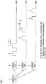
- slave units 2 to 4 transmit data to a master unit 1 in turn and receive an acknowledgment (Ack) from the master unit 1, as illustrated in FIG. 1 .
- Ack acknowledgment
- a mark “X” indicates a period when the slave unit transmits the data to the master unit
- a mark “Y” indicates a period when the master unit transmits the acknowledgment to the slave unit.
- marks "t1" and "t2" correspond to a period after transmission from the master unit is completed until a certain slave unit begins data transmission.
- the data transmission from another slave unit cannot be performed during a period when the certain slave unit transmits the data to the master unit or the master unit transmits the acknowledgment to the certain slave unit, and therefore a period such as the "t1" needs to be set so that the communications of different slave units do not overlap with each other.
- each slave unit begins the data transmission according to the judgment of oneself. In this case, the period after a certain slave unit completes the communication with the master unit until another slave unit begins the communication with the master unit may become indefinite.
- the period t1 after the master unit 1 transmits the acknowledgment to the slave unit 2 until a slave unit 3 transmits the data to the master unit 1 differs from the period t2 after the master unit 1 transmits the acknowledgment to the slave unit 3 until the slave unit 4 transmits the data to the master unit 1. For this reason, depending on the setting of the period such as the t1, it takes a long time until the main unit completes the communication with the plurality of slave units.
- each of the slave units 2 to 4 includes a GPS (Global Positioning System) module, it can transmit the data to the master unit 1 at a predetermined time.
- GPS Global Positioning System
- system times set in the inside of the slave units 2 to 4 are synchronized with each other, and a time necessary for the whole communication can be shortened.
- the manufacturing cost of the slave units 2 to 4 increases, and the power consumption of the slave units 2 to 4 increases.
- the GPS module is used, it is not easy to receive an electric wave of the GPS in doors.
- a wireless communication device (11) that communicates with a plurality of slave units (21), including: a transmitting means (14) configured to transmit a data transmission instruction including a first identification information of a single slave unit among the plurality of slave units; a receiving means (14) configured to receive data corresponding to the data transmission instruction from the single slave unit; wherein the transmitting means transmits to the plurality of slave units acknowledgment data which has incorporated second identification information into an acknowledgment to the data received from the single slave unit, the second identification information indicating another slave unit which transmits data corresponding to a next data transmission instruction to the wireless communication device.
- a wireless communication system having a master unit (11) and a plurality of slave units (21), including: the master unit (11) including: a first transmitting means (14) configured to transmit a data transmission instruction including a first identification information of a single slave unit among the plurality of slave units; a first receiving means (14) configured to receive data corresponding to the data transmission instruction from the single slave unit; wherein the first transmitting means transmits to the plurality of slave units acknowledgment data which has incorporated second identification information into an acknowledgment to the single slave unit, the second identification information indicating another slave unit which transmits data corresponding to a next data transmission instruction to the master unit, each of the plurality of slave units (21) including: a second receiving means (24) configured to receive the data transmission instruction including the first identification information of the single slave unit, and the acknowledgment data; and a second transmitting means (24) configured to transmit the data corresponding to the data transmission instruction to the master unit when each of the plurality of slave units is the single slave unit corresponding to the first identification
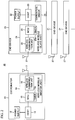
- FIG. 2 is a diagram illustrating the configuration of a wireless communication system according to a present embodiment.
- a wireless communication system 10 includes a coordinator 11 and a plurality of end devices 21.
- the coordinator 11 includes a power supply 12, a host 13 and a wireless module 14.
- the power supply 12 is a battery or an AC power supply.
- the host 13 is a mobile terminal, a computer or an electric home appliance.
- the wireless module 14 includes a microcontroller unit (MCU) 15 that controls the whole operation of the wireless module 14, and a wireless communication unit 16 that converts transmission data into an electric wave, converts a received electric wave into data, and performs various signal processing.
- the MCU 15 includes a timer 15a.
- An antenna 17 is connected to the wireless communication unit 16.
- the wireless module 14 is connected to the host 13, but may be built in the host 13.
- the wireless module 14 may be removable from the host 13.
- the MCU 15 and the wireless communication unit 16 serve as a transmitter, a receiver, a first transmitter and a first receiver.
- the end device 21 includes a power supply 22, a host 23, a wireless module 24 and a temperature sensor 28.
- the power supply 22 is a battery or an AC power supply.
- the host 23 is a mobile terminal, a computer or an electric home appliance.
- the wireless module 24 includes a MCU 25 that controls the whole operation of the wireless module 24, and a wireless communication unit 26 that converts transmission data into the electric wave, converts the received electric wave into the data, and performs various signal processing.
- the MCU 25 includes a timer 25a.
- An antenna 27 is connected to the wireless communication unit 26.
- the temperature sensor 28 measures a temperature of the place where the end device 21 is put.
- the end device 21 transmits temperature data measured by the temperature sensor 28 to the coordinator 11 via the wireless module 24.
- the MCU 25 and the wireless communication unit 26 serve as a second transmitter and a second receiver.
- the end device 21 may include other kind of sensor such as a velocity sensor as substitute for the temperature sensor 28.
- the end device 21 does not need to include the host 23, and the temperature sensor 28 may be directly connected to the MCU 25 in the wireless module 24.
- the wireless module 24 is connected to the host 23, but may be built in the host 23. Moreover, the wireless module 24 may be detachable from the host 23.
- Each of the wireless modules 14 and 24 is used for a specified low power radio using a frequency band of 920 MHz, a wireless LAN (Local Area Network), or "Bluetooth Low Energy" of a low power consumption communication specification.
- the wireless module 14 serves as the master unit
- the wireless module 24 serves as the slave unit.
- the configuration of the wireless module 14 is the same as that of the wireless module 24, and therefore functions of the master unit and the slave unit can be freely changed by setting. For example, when a setting mode in the MCU 15 of the wireless module 14 is changed to a slave unit mode, the wireless module 14 which has operated by a master unit mode operates by the slave unit mode.
- the wireless module 24 which has operated by the slave unit mode operates by the master unit mode.
- the setting mode in the MCU 15 can be changed by a changing instruction from the host 13 or a button, not shown.
- the setting mode in the MCU 25 can be changed by a changing instruction from the host 23 or a button, not shown.
- the wireless module 14 is placed on the center of the network, the N wireless modules 24 are placed around the wireless module 14 and connect to the wireless module 14 in turn.
- the wireless module 14 can perform the wireless communication with all of the wireless modules 24.
- the wireless module 24 cannot necessarily perform the wireless communication with another wireless module 24. For example, when the wireless modules 24 are placed at positions where the electric waves do not reach each other, the wireless modules 24 cannot perform the wireless communication with each other.
- the wireless module 14 performs the wireless communication with the certain wireless module 24, another wireless module 24 cannot perform the wireless communication with the wireless module 14.
- the wireless modules 24 are expressed as wireless modules 24a to 24c. Moreover, in the following description, processing which each of the wireless module 14 and the wireless module 24a to 24c performs is performed by the MCU included in the corresponding module.
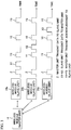
- FIG. 3 is a timing chart of data transmission of the wireless module 14 and the wireless modules 24a to 24c.
- an instruction and data transmitted from the wireless module 14 to the wireless modules 24a to 24c are designated by a dotted line, and data transmitted from the wireless modules 24a to 24c to the wireless module 14 is designated by a solid line.
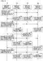
- FIG. 4 is a sequence diagram illustrating processing executed by the wireless module 14 and the wireless modules 24a to 24c.
- the wireless module 14 broadcasts data including an ID of the wireless module 24a to the wireless modules 24a to 24c (S1).
- designated by "Z" is the data which includes the ID of the wireless module 24a and is transmitted from the wireless module 14 at S 1.
- FIG. 5 is a diagram illustrating a format of the data transmitted from the wireless module 14 to the wireless modules 24a to 24c.
- the data transmitted from the wireless module 14 to the wireless modules 24a to 24c includes: a preamble 31 that is a bit string attached to a head of data and is used for the setting of gain adjustment of the wireless communication unit 26; a length 32 that indicates the length of the data; a destination ID 33 that indicates a destination of the data; a transmission source ID 34 that indicates a transmission source of the data; a data 35 that indicates a real data part; a next module ID 36 that indicates a next wireless module 24 which transmits the data to the wireless module 14; and a user definition data 37 that indicates data which a user freely sets.
- a preamble 31 that is a bit string attached to a head of data and is used for the setting of gain adjustment of the wireless communication unit 26
- a length 32 that indicates the length of the data
- a destination ID 33 that indicates a destination of the data
- a transmission source ID 34 that indicates a transmission source of the data
- a data 35 that indicates a real data part
- a next module ID 36 that indicates
- an ID of the wireless module 24a is included in the next module ID 36, and an ID of the wireless module 14 is included in the transmission source ID 34. At this time, an ID indicating a specific wireless module is not included in the destination ID 33.
- Predetermined bit strings are included in the preamble 31, the length 32, the data 35 and the user definition data 37.
- the wireless module 24a determines whether the ID of the wireless module 24a is included in the received data. When it is determined that the received data is the data transmission instruction for the wireless module 24a as a result of analysis of the received data, the wireless module 24a immediately transmits data corresponding to the data transmission instruction to the wireless module 14 (S2). In FIG 3 , designated by "X1" is the data which is transmitted from the wireless module 24a at S2 and corresponds to the data transmission instruction. The wireless module 14 receives the data from the wireless module 24a.
- the wireless modules 24b and 24c also receive the data including the ID of the wireless module 24a, and analyze the received data. However, the IDs of the wireless modules 24b and 24c are not included in the next module ID 36, and the wireless modules 24b and 24c therefore discard the received data and become standby state (S3, S4).
- the wireless module 14 which has received the data from the wireless module 24a transmits to the wireless modules 24a to 24c data including the ID of wireless module 24b and the acknowledgment to the wireless module 24a (S5).
- the ID of the wireless module 24a is included in the destination ID 33
- the ID of the wireless module 14 is included in the transmission source ID 34
- the ID of the wireless module 24b is included in the next module ID 36
- the acknowledgment to the wireless module 24a is included in the data 35.
- the predetermined bit strings are included in the preamble 31, the length 32 and the user definition data 37.
- designated by "Y1" is the data which is transmitted from the wireless module 14 at S5 and includes the ID of the wireless module 24b and the acknowledgment to the wireless module 24a.
- the wireless module 24a analyzes the data received from the wireless module 14. When it is determined that the received data is the acknowledgment as a result of analysis of the received data, the wireless module 24a becomes the standby state (S6). On the other hand, the wireless module 24b analyzes the received data. In this case, since the ID of the wireless module 24b is included in the next module ID 36, the wireless module 24b determines that the received data is the data transmission instruction for oneself, and immediately transmits data corresponding to the data transmission instruction to the wireless module 14 (S7). In FIG. 3 , designated by "X2" is the data which corresponds to the data transmission instruction and is transmitted from the wireless module 24b at S7. The wireless module 14 receives the data from the wireless module 24b.
- the wireless module 24c also analyzes the data received from the wireless module 14. However, since the ID of the wireless module 24c is not included in the destination ID 33 and the next module ID 36, the wireless module 24c discards the received data and becomes the standby state (S8).
- the wireless module 14 which has received the data from the wireless module 24b transmits to the wireless modules 24a to 24c data including the ID of wireless module 24c and the acknowledgment to the wireless module 24b (S9).
- the ID of the wireless module 24b is included in the destination ID 33
- the ID of the wireless module 14 is included in the transmission source ID 34
- the ID of the wireless module 24c is included in the next module ID 36
- the acknowledgment to the wireless module 24b is included in the data 35.
- the predetermined bit strings are included in the preamble 31, the length 32 and the user definition data 37.
- designated by "Y2" is the data which is transmitted from the wireless module 14 at S9 and includes the ID of the wireless module 24c and the acknowledgment to the wireless module 24b.
- the wireless module 24a analyzes the data received from the wireless module 14. In this case, since the ID of the wireless module 24a is not included in the destination ID 33 and the next module ID 36, the wireless module 24a discards the received data and becomes the standby state (S10).
- the wireless module 24b becomes the standby state (S11). Since the ID of the wireless module 24c is included in the next module ID 36 of the received data, the wireless module 24c determines that the received data is the data transmission instruction for oneself, and transmits data corresponding to the data transmission instruction to the wireless module 14 (S12). In FIG. 3 , designated by "X3" is the data which corresponds to the data transmission instruction and is transmitted from the wireless module 24c at S12. The wireless module 14 receives the data from the wireless module 24c.
- the wireless module 14 which has received the data from the wireless module 24c transmits to the wireless modules 24a to 24c data including the acknowledgment to the wireless module 24c (S13).
- the ID of the wireless module 24c is set to the destination ID 33, the wireless module 14 does not transmit the data transmission instruction to the wireless modules 24a to 24c at S13. Therefore, the ID of the wireless module is not set to the next module ID 36.
- designated by "Y3" is the data which is transmitted from the wireless module 14 at S 13 and includes the acknowledgment to the wireless module 24c.
- Each of the wireless module 24a and 24b analyzes the data received from the wireless module 14.
- each of the wireless module 24a and 24b discards the received data and becomes the standby state (S 14, S 15).
- the wireless module 24c becomes the standby state (S 16).
- the wireless module 14 After the wireless module 14 receives the data from the wireless module 24, the wireless module 14 broadcasts to all the wireless modules 24 data that has incorporated the next module ID 36 into the acknowledgment to the wireless module 24, the next module ID 36 indicating another wireless module 24 which should transmit data to the wireless module 14 next. Therefore, the wireless module 24 specified by the next module ID 36 can determine whether to need to transmit data to the wireless module 14 by analyzing the next module ID 36, and can transmit the data to the wireless module 14. As a result, it is possible to reduce a time required before the master unit completes the communication with the plurality of slave units, compared with a case where the slave unit itself determines timing of transmitting the data to the master unit.
- the wireless module 14 includes the ID of the wireless module 24a in the data first transmitted to the wireless modules 24a to 24c, but the ID included in the data first transmitted to the wireless modules 24a to 24c may be the ID of the wireless module 24b or 24c.
- the data “Z” includes the ID of the wireless module 24a as the next module ID 36.
- the wireless module 24a receives the data "Z”
- the wireless module 24a immediately transmits the data "X1” corresponding to the data transmission instruction to the wireless module 14.
- the data “Y1” includes the ID of the wireless module 24b as the next module ID 36.
- the wireless module 24b receives the data "Y1”
- the wireless module 24b immediately transmits the data "X2" corresponding to the data transmission instruction to the wireless module 14.
- the data “Y2” includes the ID of the wireless module 24c as the next module ID 36.
- the wireless module 24c receives the data "Y2”
- the wireless module 24c immediately transmits the data "X3" corresponding to the data transmission instruction to the wireless module 14.
- each of the wireless modules 24a to 24c may transmit the data corresponding to the data transmission instruction after a time set beforehand in the MCU 25 has elapsed.
- the elapsed time i.e., the time set beforehand in the MCU 25
- the slave unit receives the ID of oneself until the slave unit transmits the data corresponding to the data transmission instruction to the master unit is set to the MCU 25 from the host 23
- an elapsed time 38 indicating a time period after the slave unit receives the ID of oneself until the slave unit transmits the data corresponding to the data transmission instruction to the master unit may be added to the data format illustrated in FIG. 5 , as illustrated in FIG. 6 .
- the elapsed time 38 is included in the data transmitted from the wireless module 14 to the wireless modules 24a to 24c.
- FIG. 7 is a timing chart of the data transmission of the wireless module 14 and the wireless modules 24a to 24c when a time Ta is set as the elapsed time 38.
- the data “Z” includes the time Ta as the elapsed time 38, and the ID of the wireless module 24a as the next module ID 36.
- the wireless module 24a receives the data "Z”
- the time Ta elapses
- the wireless module 24a transmits the data "X1" corresponding to the data transmission instruction to the wireless module 14.
- the data "Y1” includes the time Ta as the elapsed time 38, and the ID of the wireless module 24b as the next module ID 36.
- the wireless module 24b receives the data "Y1”
- the data "Y2" includes the time Ta as the elapsed time 38, and the ID of the wireless module 24c as the next module ID 36.
- the wireless module 24c receives the data "Y2"
- the time Ta elapses
- the wireless module 24c transmits the data "X3" corresponding to the data transmission instruction to the wireless module 14.
- each of the wireless modules 24a to 24c receives the data including the time Ta as the elapsed time 38 and the ID of oneself as the next module ID 36, the time Ta elapses, and then each of the wireless modules 24a to 24c transmits the data corresponding to the data transmission instruction to the wireless module 14. Also in this case, it is possible to reduce a time required before the master unit completes the communication with the plurality of slave units.
- FIG 8 is a timing chart illustrating a variation of the data transmission of the wireless module 14 and the wireless modules 24a to 24c.
- the wireless module 14 after first transmitting the data "Y1" indicating the ID of the wireless module 24b and the acknowledgment to the wireless module 24a to the wireless modules 24a to 24c, the wireless module 14 cannot receive the data "X2" corresponding to the data transmission instruction from the wireless module 24b during a time Tb. For this reason, the wireless module 14 transmits the data "Y1" to the wireless modules 24a to 24c again after the time Tb has elapsed. In an example of FIG. 8 , after retransmitting the data "Y1", the wireless module 14 normally receives the data "X2" corresponding to the data transmission instruction from the wireless module 24b.
- the time Tb for requiring the wireless modules 24a to 24c to retransmit the data corresponding to the data transmission instruction is set to the MCU 15 of the wireless module 14 from the host 13.
- FIG 9 is a diagram illustrating a variation of the format of the data transmitted from the wireless module 14 to the wireless modules 24a to 24c. Corresponding parts to those in the format of FIG 5 are designated by the same reference numerals, and description thereof is omitted.
- the data illustrated in FIG. 9 includes a previous module ID 39 indicating, immediately before the data is transmitted to the wireless modules 24a to 24c, the wireless module 24 which has transmitted data to the wireless module 14.
- the previous module ID 39 serves as information indicating that the data of FIG 9 is the acknowledgment to the wireless module 24 which has the most recently transmitted the data to the wireless module 14.
- the destination ID 33 indicates a destination of the acknowledgment with respect to the data received from the wireless module 24. However, in FIG. 9 , the destination ID 33 indicates a destination of the data transmission instruction. Then, the data transmission instruction enters in the data 35 of FIG 9 .
- the data “Z” transmitted from the wireless module 14 is the data transmission instruction with respect to the wireless module 24a.
- the ID of the wireless module 24a is included in the destination ID 33 of the data "Z”
- the ID of the wireless module 14 is included in the transmission source ID 34
- the data transmission instruction is included in the data 35.
- the previous module ID 39 is empty data.
- the predetermined bit strings are included in the preamble 31, the length 32 and the user definition data 37.
- the wireless module 24a When the data "Z" is transmitted to the wireless modules 24a to 24c, the wireless module 24a whose ID is set to the destination ID 33 transmits the data "X1" corresponding to the data transmission instruction to the wireless module 14. Since each of the IDs of the wireless modules 24b and 24c is not included in the destination ID 33 and the previous module ID 39, each of the wireless modules 24b and 24c discards the data "Z" and becomes the standby state.
- the wireless module 14 transmits the data "Y1" as the acknowledgment to the wireless module 24a and as the data transmission instruction to the wireless module 24.
- the ID of the wireless module 24b is included in the destination ID 33 of the data "Y1"
- the ID of the wireless module 14 is included in the transmission source ID 34
- the data transmission instruction is included in the data 35. Since the wireless module 24a has the most recently transmitted the data "X1" to the wireless module 14, the ID of the wireless module 24a is included in the previous module ID 39.
- the predetermined bit strings are included in the preamble 31, the length 32 and the user definition data 37.
- the wireless module 24a determines that the data "Y1" is the acknowledgment, and becomes the standby state. Moreover, since the ID of the wireless module 24b is included in the destination ID 33, the wireless module 24b transmits the data "X2" corresponding to the data transmission instruction to the wireless module 14. Since the ID of the wireless module 24c is not included in the destination ID 33 and the previous module ID 39, the wireless module 24c discards the data "Y1" and becomes the standby state.
- the ID of the wireless module 24c is included in the destination ID 33 of the data "Y2"
- the ID of the wireless module 14 is included in the transmission source ID 34
- the data transmission instruction is included in the data 35. Since the wireless module 24b has the most recently transmitted the data "X2" to the wireless module 14, the ID of the wireless module 24b is included in the previous module ID 39.
- the predetermined bit strings are included in the preamble 31, the length 32 and the user definition data 37.
- the wireless module 24a When the data "Y2" is transmitted to the wireless modules 24a to 24c, the ID of the wireless module 24a is not included in the destination ID 33 and the previous module ID 39. Therefore, the wireless module 24a discards the data "Y2" and becomes the standby state. Since the ID of the wireless module 24b is included in the previous module ID 39, the wireless module 24b determines that the data "Y2" is the acknowledgment, and becomes the standby state. Since the ID of the wireless module 24c is included in the destination ID 33, the wireless module 24c transmits the data "X3" corresponding to the data transmission instruction to the wireless module 14.
- the empty data is included in the destination ID 33 of the data "Y3"
- the ID of the wireless module 14 is included in the transmission source ID 34
- the data transmission instruction is included in the data 35. Since the wireless module 24c has the most recently transmitted the data "X3" to the wireless module 14, the ID of the wireless module 24c is included in the previous module ID 39.
- the predetermined bit strings are included in the preamble 31, the length 32 and the user definition data 37.
- the wireless modules 24a to 24c When the data "Y3" is transmitted to the wireless modules 24a to 24c, the IDs of the wireless modules 24a and 24b are not included in the destination ID 33 and the previous module ID 39. Therefore, each of the wireless modules 24a and 24b discards the data "Y3" and becomes the standby state. Since the ID of the wireless module 24c is included in the previous module ID 39, the wireless module 24c determines that the data "Y3" is the acknowledgment, and becomes the standby state.
- the wireless module 14 transmits to all the wireless modules 24 data that incorporated the previous module ID 39 into the data transmission instruction to a next wireless module 24, the previous module ID 39 indicating the wireless module 24 has the most recently transmitted the data to the wireless module 14. Therefore, the wireless module 24 specified by the destination ID 33 can determine whether to need to transmit the data to the wireless module 14, and can immediately transmit the data to the wireless module 14. Then, the wireless module 24 specified by the previous module ID 39 receives the acknowledgment, and can confirm that the data transmission has succeeded. As a result, it is possible to reduce the time required before the master unit completes the communication with the plurality of slave units, compared with a case where the slave unit transmits the data to the master unit at appropriate timing.
- the elapsed time 38 indicating the time period after the slave unit receives the ID of oneself until the slave unit transmits the data corresponding to the data transmission instruction to the master unit may be added to the data format of FIG 9 , as illustrated in FIG 6 .
- the wireless module 14 may transmit the data "Y1" to the wireless modules 24a to 24c again after the time Tb has elapsed, as illustrated in FIG 8 .
- a wireless communication device that communicates with a plurality of slave units, characterized by comprising:
- the wireless communication device according to statement S 1, wherein the acknowledgment data includes time information indicating a time required after the another slave unit receives the second identification information until the another slave unit transmits the data corresponding to the next data transmission instruction to the wireless communication device.
- a wireless communication device that communicates with a plurality of slave units, characterized by comprising:
- a wireless communication system having a master unit and a plurality of slave units, characterized by comprising:
- a wireless communication system having a master unit and a plurality of slave units, characterized by comprising:
Landscapes
- Engineering & Computer Science (AREA)
- Computer Networks & Wireless Communication (AREA)
- Signal Processing (AREA)
- Mobile Radio Communication Systems (AREA)
Abstract
Description
- The present invention relates to a wireless communication device and a wireless communication system.
- Conventionally, there has been known a wireless communication system in which devices communicate with each other by a short range wireless communication technique (e.g. see Japanese Laid-open Patent Publication No.
2009-77296 - In a Japanese wireless radio act, before a transmitter performing wireless communication begins the transmission of an electric wave, it is necessary to check whether a channel to be used is used for the transmission with another transmitter based on an intended use and a use frequency band. This is called a carrier sense. If the channel to be used is in use by the another transmitter, the transmitter cannot perform the transmission by using the channel, and the transmitter needs to perform the transmission after the another transmitter completes the transmission or to perform the transmission by using another channel. Here, also when the another channel is used, it is necessary to perform the carrier sense with the use of the another channel again before the transmission.
- Here, it is assumed that, in a short range wireless communication,
slave units 2 to 4 transmit data to amaster unit 1 in turn and receive an acknowledgment (Ack) from themaster unit 1, as illustrated inFIG. 1 . InFIG 1 , a mark "X" indicates a period when the slave unit transmits the data to the master unit, and a mark "Y" indicates a period when the master unit transmits the acknowledgment to the slave unit. Each of marks "t1" and "t2" correspond to a period after transmission from the master unit is completed until a certain slave unit begins data transmission. The data transmission from another slave unit cannot be performed during a period when the certain slave unit transmits the data to the master unit or the master unit transmits the acknowledgment to the certain slave unit, and therefore a period such as the "t1" needs to be set so that the communications of different slave units do not overlap with each other. In a situation where the respective slave units are not synchronized with each other, each slave unit begins the data transmission according to the judgment of oneself. In this case, the period after a certain slave unit completes the communication with the master unit until another slave unit begins the communication with the master unit may become indefinite. In an example ofFIG .1 , the period t1 after themaster unit 1 transmits the acknowledgment to theslave unit 2 until aslave unit 3 transmits the data to themaster unit 1 differs from the period t2 after themaster unit 1 transmits the acknowledgment to theslave unit 3 until theslave unit 4 transmits the data to themaster unit 1. For this reason, depending on the setting of the period such as the t1, it takes a long time until the main unit completes the communication with the plurality of slave units. - Moreover, when each of the
slave units 2 to 4 includes a GPS (Global Positioning System) module, it can transmit the data to themaster unit 1 at a predetermined time. In this case, system times set in the inside of theslave units 2 to 4 are synchronized with each other, and a time necessary for the whole communication can be shortened. However, the manufacturing cost of theslave units 2 to 4 increases, and the power consumption of theslave units 2 to 4 increases. Moreover, when the GPS module is used, it is not easy to receive an electric wave of the GPS in doors. - It is an object of the present invention to provide a wireless communication device and a wireless communication system that can shorten a time necessary for the whole communication without synchronization with a system time of another device.
- According to an aspect of the present invention, there is provided a wireless communication device (11) that communicates with a plurality of slave units (21), including: a transmitting means (14) configured to transmit a data transmission instruction including a first identification information of a single slave unit among the plurality of slave units; a receiving means (14) configured to receive data corresponding to the data transmission instruction from the single slave unit; wherein the transmitting means transmits to the plurality of slave units acknowledgment data which has incorporated second identification information into an acknowledgment to the data received from the single slave unit, the second identification information indicating another slave unit which transmits data corresponding to a next data transmission instruction to the wireless communication device.
- According to another aspect of the present invention, there is provided a wireless communication system having a master unit (11) and a plurality of slave units (21), including: the master unit (11) including: a first transmitting means (14) configured to transmit a data transmission instruction including a first identification information of a single slave unit among the plurality of slave units; a first receiving means (14) configured to receive data corresponding to the data transmission instruction from the single slave unit; wherein the first transmitting means transmits to the plurality of slave units acknowledgment data which has incorporated second identification information into an acknowledgment to the single slave unit, the second identification information indicating another slave unit which transmits data corresponding to a next data transmission instruction to the master unit, each of the plurality of slave units (21) including: a second receiving means (24) configured to receive the data transmission instruction including the first identification information of the single slave unit, and the acknowledgment data; and a second transmitting means (24) configured to transmit the data corresponding to the data transmission instruction to the master unit when each of the plurality of slave units is the single slave unit corresponding to the first identification information, and transmit the data corresponding to the next data transmission instruction to the master unit when each of the plurality of slave units is the another slave unit corresponding to the second identification information.
-
-
FIG 1 is a timing chart of data transmission of a master unit and slave units; -
FIG 2 is a diagram illustrating the configuration of a wireless communication system according to a present embodiment; -
FIG. 3 is a timing chart of data transmission of awireless module 14 andwireless modules 24a to 24c; -
FIG. 4 is a sequence diagram illustrating processing executed by thewireless module 14 and thewireless modules 24a to 24c; -
FIG 5 is a diagram illustrating a format of data transmitted from thewireless module 14 to thewireless modules 24a to 24c; -
FIG. 6 is a diagram illustrating a variation of the format of the data transmitted from thewireless module 14 to thewireless modules 24a to 24c; -
FIG 7 is a timing chart of the data transmission of thewireless module 14 and thewireless modules 24a to 24c when a time Ta is set as an elapsedtime 38; -
FIG 8 is a timing chart illustrating a variation of the data transmission of thewireless module 14 and thewireless modules 24a to 24c; and -
FIG. 9 is a diagram illustrating a variation of the format of the data transmitted from thewireless module 14 to thewireless modules 24a to 24c. - A description will now be given of an embodiment according to the present invention with reference to drawings.
-
FIG. 2 is a diagram illustrating the configuration of a wireless communication system according to a present embodiment. - A
wireless communication system 10 according to the embodiment includes acoordinator 11 and a plurality ofend devices 21. Thecoordinator 11 includes apower supply 12, ahost 13 and awireless module 14. Thepower supply 12 is a battery or an AC power supply. Thehost 13 is a mobile terminal, a computer or an electric home appliance. Thewireless module 14 includes a microcontroller unit (MCU) 15 that controls the whole operation of thewireless module 14, and awireless communication unit 16 that converts transmission data into an electric wave, converts a received electric wave into data, and performs various signal processing. The MCU 15 includes atimer 15a. Anantenna 17 is connected to thewireless communication unit 16. - The
wireless module 14 is connected to thehost 13, but may be built in thehost 13. Thewireless module 14 may be removable from thehost 13. The MCU 15 and thewireless communication unit 16 serve as a transmitter, a receiver, a first transmitter and a first receiver. - The
end device 21 includes apower supply 22, ahost 23, awireless module 24 and atemperature sensor 28. Thepower supply 22 is a battery or an AC power supply. Thehost 23 is a mobile terminal, a computer or an electric home appliance. Thewireless module 24 includes aMCU 25 that controls the whole operation of thewireless module 24, and awireless communication unit 26 that converts transmission data into the electric wave, converts the received electric wave into the data, and performs various signal processing. The MCU 25 includes atimer 25a. Anantenna 27 is connected to thewireless communication unit 26. Thetemperature sensor 28 measures a temperature of the place where theend device 21 is put. Theend device 21 transmits temperature data measured by thetemperature sensor 28 to thecoordinator 11 via thewireless module 24. The MCU 25 and thewireless communication unit 26 serve as a second transmitter and a second receiver. - The
end device 21 may include other kind of sensor such as a velocity sensor as substitute for thetemperature sensor 28. Theend device 21 does not need to include thehost 23, and thetemperature sensor 28 may be directly connected to theMCU 25 in thewireless module 24. Thewireless module 24 is connected to thehost 23, but may be built in thehost 23. Moreover, thewireless module 24 may be detachable from thehost 23. - Each of the
wireless modules wireless module 14 serves as the master unit, and thewireless module 24 serves as the slave unit. Here, the configuration of thewireless module 14 is the same as that of thewireless module 24, and therefore functions of the master unit and the slave unit can be freely changed by setting. For example, when a setting mode in theMCU 15 of thewireless module 14 is changed to a slave unit mode, thewireless module 14 which has operated by a master unit mode operates by the slave unit mode. On the contrary, when the setting mode in theMCU 25 of thewireless module 24 is changed to the master unit mode, thewireless module 24 which has operated by the slave unit mode operates by the master unit mode. The setting mode in theMCU 15 can be changed by a changing instruction from thehost 13 or a button, not shown. The setting mode in theMCU 25 can be changed by a changing instruction from thehost 23 or a button, not shown. - The
wireless communication system 10 according to the present embodiment is a 1:N (N = an integer of 1 or more) wireless communication system in which thesingle wireless module 14 as the master unit communicates with theN wireless modules 24 as the slave units in turn. That is, thewireless communication system 10 constitutes a star type wireless communication network. Thewireless module 14 is placed on the center of the network, theN wireless modules 24 are placed around thewireless module 14 and connect to thewireless module 14 in turn. Thewireless module 14 can perform the wireless communication with all of thewireless modules 24. However, thewireless module 24 cannot necessarily perform the wireless communication with anotherwireless module 24. For example, when thewireless modules 24 are placed at positions where the electric waves do not reach each other, thewireless modules 24 cannot perform the wireless communication with each other. When thewireless module 14 performs the wireless communication with thecertain wireless module 24, anotherwireless module 24 cannot perform the wireless communication with thewireless module 14. - In the following description, to distinguish the
wireless modules 24 included in the plurality ofend devices 21, thewireless modules 24 are expressed aswireless modules 24a to 24c. Moreover, in the following description, processing which each of thewireless module 14 and thewireless module 24a to 24c performs is performed by the MCU included in the corresponding module. -
FIG. 3 is a timing chart of data transmission of thewireless module 14 and thewireless modules 24a to 24c. InFIG. 3 , an instruction and data transmitted from thewireless module 14 to thewireless modules 24a to 24c are designated by a dotted line, and data transmitted from thewireless modules 24a to 24c to thewireless module 14 is designated by a solid line.FIG. 4 is a sequence diagram illustrating processing executed by thewireless module 14 and thewireless modules 24a to 24c. - First, in
FIG 4 , thewireless module 14 broadcasts data including an ID of thewireless module 24a to thewireless modules 24a to 24c (S1). InFIG 3 , designated by "Z" is the data which includes the ID of thewireless module 24a and is transmitted from thewireless module 14 atS 1. -
FIG. 5 is a diagram illustrating a format of the data transmitted from thewireless module 14 to thewireless modules 24a to 24c. - The data transmitted from the
wireless module 14 to thewireless modules 24a to 24c includes: apreamble 31 that is a bit string attached to a head of data and is used for the setting of gain adjustment of thewireless communication unit 26; alength 32 that indicates the length of the data; adestination ID 33 that indicates a destination of the data; atransmission source ID 34 that indicates a transmission source of the data; adata 35 that indicates a real data part; anext module ID 36 that indicates anext wireless module 24 which transmits the data to thewireless module 14; and auser definition data 37 that indicates data which a user freely sets. When an ID of thewireless module 24 is included in thenext module ID 36, this data becomes a data transmission instruction that instructs thewireless module 24 to transmit the data to thewireless module 14. - In the data transmitted at S1 of
FIG. 4 , an ID of thewireless module 24a is included in thenext module ID 36, and an ID of thewireless module 14 is included in thetransmission source ID 34. At this time, an ID indicating a specific wireless module is not included in thedestination ID 33. Predetermined bit strings are included in thepreamble 31, thelength 32, thedata 35 and theuser definition data 37. - Returning to
FIG 4 , thewireless module 24a determines whether the ID of thewireless module 24a is included in the received data. When it is determined that the received data is the data transmission instruction for thewireless module 24a as a result of analysis of the received data, thewireless module 24a immediately transmits data corresponding to the data transmission instruction to the wireless module 14 (S2). InFIG 3 , designated by "X1" is the data which is transmitted from thewireless module 24a at S2 and corresponds to the data transmission instruction. Thewireless module 14 receives the data from thewireless module 24a. - The
wireless modules wireless module 24a, and analyze the received data. However, the IDs of thewireless modules next module ID 36, and thewireless modules - Next, the
wireless module 14 which has received the data from thewireless module 24a transmits to thewireless modules 24a to 24c data including the ID ofwireless module 24b and the acknowledgment to thewireless module 24a (S5). In the data transmitted at S5, the ID of thewireless module 24a is included in thedestination ID 33, the ID of thewireless module 14 is included in thetransmission source ID 34, the ID of thewireless module 24b is included in thenext module ID 36, and the acknowledgment to thewireless module 24a is included in thedata 35. The predetermined bit strings are included in thepreamble 31, thelength 32 and theuser definition data 37. InFIG. 3 , designated by "Y1" is the data which is transmitted from thewireless module 14 at S5 and includes the ID of thewireless module 24b and the acknowledgment to thewireless module 24a. - The
wireless module 24a analyzes the data received from thewireless module 14. When it is determined that the received data is the acknowledgment as a result of analysis of the received data, thewireless module 24a becomes the standby state (S6). On the other hand, thewireless module 24b analyzes the received data. In this case, since the ID of thewireless module 24b is included in thenext module ID 36, thewireless module 24b determines that the received data is the data transmission instruction for oneself, and immediately transmits data corresponding to the data transmission instruction to the wireless module 14 (S7). InFIG. 3 , designated by "X2" is the data which corresponds to the data transmission instruction and is transmitted from thewireless module 24b at S7. Thewireless module 14 receives the data from thewireless module 24b. Moreover, thewireless module 24c also analyzes the data received from thewireless module 14. However, since the ID of thewireless module 24c is not included in thedestination ID 33 and thenext module ID 36, thewireless module 24c discards the received data and becomes the standby state (S8). - Next, the
wireless module 14 which has received the data from thewireless module 24b transmits to thewireless modules 24a to 24c data including the ID ofwireless module 24c and the acknowledgment to thewireless module 24b (S9). In the data transmitted at S9, the ID of thewireless module 24b is included in thedestination ID 33, the ID of thewireless module 14 is included in thetransmission source ID 34, the ID of thewireless module 24c is included in thenext module ID 36, and the acknowledgment to thewireless module 24b is included in thedata 35. The predetermined bit strings are included in thepreamble 31, thelength 32 and theuser definition data 37. InFIG. 3 , designated by "Y2" is the data which is transmitted from thewireless module 14 at S9 and includes the ID of thewireless module 24c and the acknowledgment to thewireless module 24b. - The
wireless module 24a analyzes the data received from thewireless module 14. In this case, since the ID of thewireless module 24a is not included in thedestination ID 33 and thenext module ID 36, thewireless module 24a discards the received data and becomes the standby state (S10). - On the other hand, when it is determined that the received data is the acknowledgment for oneself as a result of analysis of the received data, the
wireless module 24b becomes the standby state (S11). Since the ID of thewireless module 24c is included in thenext module ID 36 of the received data, thewireless module 24c determines that the received data is the data transmission instruction for oneself, and transmits data corresponding to the data transmission instruction to the wireless module 14 (S12). InFIG. 3 , designated by "X3" is the data which corresponds to the data transmission instruction and is transmitted from thewireless module 24c at S12. Thewireless module 14 receives the data from thewireless module 24c. - Finally, the
wireless module 14 which has received the data from thewireless module 24c transmits to thewireless modules 24a to 24c data including the acknowledgment to thewireless module 24c (S13). Although the ID of thewireless module 24c is set to thedestination ID 33, thewireless module 14 does not transmit the data transmission instruction to thewireless modules 24a to 24c at S13. Therefore, the ID of the wireless module is not set to thenext module ID 36. InFIG. 3 , designated by "Y3" is the data which is transmitted from thewireless module 14 atS 13 and includes the acknowledgment to thewireless module 24c. Each of thewireless module wireless module 14. Since the ID of oneself is not included in thedestination ID 33 of the received data, each of thewireless module S 14, S 15). When it is determined that the received data from thewireless module 14 is the acknowledgment for oneself, thewireless module 24c becomes the standby state (S 16). - Thus, after the
wireless module 14 receives the data from thewireless module 24, thewireless module 14 broadcasts to all thewireless modules 24 data that has incorporated thenext module ID 36 into the acknowledgment to thewireless module 24, thenext module ID 36 indicating anotherwireless module 24 which should transmit data to thewireless module 14 next. Therefore, thewireless module 24 specified by thenext module ID 36 can determine whether to need to transmit data to thewireless module 14 by analyzing thenext module ID 36, and can transmit the data to thewireless module 14. As a result, it is possible to reduce a time required before the master unit completes the communication with the plurality of slave units, compared with a case where the slave unit itself determines timing of transmitting the data to the master unit. - Moreover, in the present embodiment, it is not necessary to synchronize the time setting in the inside of the
wireless module 14 with the time setting in the inside of thewireless module 24. Moreover, it is not necessary to synchronize the time settings in the inside of thewireless modules 24 with each other. - In
FIG 4 , thewireless module 14 includes the ID of thewireless module 24a in the data first transmitted to thewireless modules 24a to 24c, but the ID included in the data first transmitted to thewireless modules 24a to 24c may be the ID of thewireless module - In
FIG. 3 , the data "Z" includes the ID of thewireless module 24a as thenext module ID 36. When thewireless module 24a receives the data "Z", thewireless module 24a immediately transmits the data "X1" corresponding to the data transmission instruction to thewireless module 14. The data "Y1" includes the ID of thewireless module 24b as thenext module ID 36. When thewireless module 24b receives the data "Y1", thewireless module 24b immediately transmits the data "X2" corresponding to the data transmission instruction to thewireless module 14. The data "Y2" includes the ID of thewireless module 24c as thenext module ID 36. When thewireless module 24c receives the data "Y2", thewireless module 24c immediately transmits the data "X3" corresponding to the data transmission instruction to thewireless module 14. - Unlike the example of
FIGs. 3 and4 , when each of thewireless modules 24a to 24c receives data in which the ID of oneself is set as thenext module ID 36, each of thewireless modules 24a to 24c may transmit the data corresponding to the data transmission instruction after a time set beforehand in theMCU 25 has elapsed. The elapsed time (i.e., the time set beforehand in the MCU 25) after the slave unit receives the ID of oneself until the slave unit transmits the data corresponding to the data transmission instruction to the master unit is set to theMCU 25 from thehost 23 - Moreover, an elapsed
time 38 indicating a time period after the slave unit receives the ID of oneself until the slave unit transmits the data corresponding to the data transmission instruction to the master unit may be added to the data format illustrated inFIG. 5 , as illustrated inFIG. 6 . In this case, the elapsedtime 38 is included in the data transmitted from thewireless module 14 to thewireless modules 24a to 24c. -
FIG. 7 is a timing chart of the data transmission of thewireless module 14 and thewireless modules 24a to 24c when a time Ta is set as the elapsedtime 38. - In
FIG. 7 , the data "Z" includes the time Ta as the elapsedtime 38, and the ID of thewireless module 24a as thenext module ID 36. When thewireless module 24a receives the data "Z", the time Ta elapses, and then thewireless module 24a transmits the data "X1" corresponding to the data transmission instruction to thewireless module 14. The data "Y1" includes the time Ta as the elapsedtime 38, and the ID of thewireless module 24b as thenext module ID 36. When thewireless module 24b receives the data "Y1", the time Ta elapses, and then thewireless module 24b transmits the data "X2" corresponding to the data transmission instruction to thewireless module 14. The data "Y2" includes the time Ta as the elapsedtime 38, and the ID of thewireless module 24c as thenext module ID 36. When thewireless module 24c receives the data "Y2", the time Ta elapses, and then thewireless module 24c transmits the data "X3" corresponding to the data transmission instruction to thewireless module 14. - Thus, when each of the
wireless modules 24a to 24c receives the data including the time Ta as the elapsedtime 38 and the ID of oneself as thenext module ID 36, the time Ta elapses, and then each of thewireless modules 24a to 24c transmits the data corresponding to the data transmission instruction to thewireless module 14. Also in this case, it is possible to reduce a time required before the master unit completes the communication with the plurality of slave units. -
FIG 8 is a timing chart illustrating a variation of the data transmission of thewireless module 14 and thewireless modules 24a to 24c. - In
FIG 8 , after first transmitting the data "Y1" indicating the ID of thewireless module 24b and the acknowledgment to thewireless module 24a to thewireless modules 24a to 24c, thewireless module 14 cannot receive the data "X2" corresponding to the data transmission instruction from thewireless module 24b during a time Tb. For this reason, thewireless module 14 transmits the data "Y1" to thewireless modules 24a to 24c again after the time Tb has elapsed. In an example ofFIG. 8 , after retransmitting the data "Y1", thewireless module 14 normally receives the data "X2" corresponding to the data transmission instruction from thewireless module 24b. - Thus, when the communication between the
wireless modules wireless modules - The time Tb for requiring the
wireless modules 24a to 24c to retransmit the data corresponding to the data transmission instruction is set to theMCU 15 of thewireless module 14 from thehost 13. -
FIG 9 is a diagram illustrating a variation of the format of the data transmitted from thewireless module 14 to thewireless modules 24a to 24c. Corresponding parts to those in the format ofFIG 5 are designated by the same reference numerals, and description thereof is omitted. - The data illustrated in
FIG. 9 includes aprevious module ID 39 indicating, immediately before the data is transmitted to thewireless modules 24a to 24c, thewireless module 24 which has transmitted data to thewireless module 14. Theprevious module ID 39 serves as information indicating that the data ofFIG 9 is the acknowledgment to thewireless module 24 which has the most recently transmitted the data to thewireless module 14. - In
FIG 5 , thedestination ID 33 indicates a destination of the acknowledgment with respect to the data received from thewireless module 24. However, inFIG. 9 , thedestination ID 33 indicates a destination of the data transmission instruction. Then, the data transmission instruction enters in thedata 35 ofFIG 9 . - Hereinafter, a description will given of a timing chart of the data transmission of the
wireless module 14 and thewireless modules 24a to 24c inFIG. 3 with the use of the data format ofFIG. 9 . - It is assumed that the data "Z" transmitted from the
wireless module 14 is the data transmission instruction with respect to thewireless module 24a. In this case, the ID of thewireless module 24a is included in thedestination ID 33 of the data "Z", the ID of thewireless module 14 is included in thetransmission source ID 34, and the data transmission instruction is included in thedata 35. Here, there is nowireless module 24 which has transmitted data to thewireless module 14 before the transmission of the data "Z", and therefore theprevious module ID 39 is empty data. The predetermined bit strings are included in thepreamble 31, thelength 32 and theuser definition data 37. - When the data "Z" is transmitted to the
wireless modules 24a to 24c, thewireless module 24a whose ID is set to thedestination ID 33 transmits the data "X1" corresponding to the data transmission instruction to thewireless module 14. Since each of the IDs of thewireless modules destination ID 33 and theprevious module ID 39, each of thewireless modules - Next, the
wireless module 14 transmits the data "Y1" as the acknowledgment to thewireless module 24a and as the data transmission instruction to thewireless module 24. The ID of thewireless module 24b is included in thedestination ID 33 of the data "Y1", the ID of thewireless module 14 is included in thetransmission source ID 34, and the data transmission instruction is included in thedata 35. Since thewireless module 24a has the most recently transmitted the data "X1" to thewireless module 14, the ID of thewireless module 24a is included in theprevious module ID 39. The predetermined bit strings are included in thepreamble 31, thelength 32 and theuser definition data 37. - When the data "Y1" is transmitted to the
wireless modules 24a to 24c, the ID of thewireless module 24a is included in theprevious module ID 39. Therefore, thewireless module 24a determines that the data "Y1" is the acknowledgment, and becomes the standby state. Moreover, since the ID of thewireless module 24b is included in thedestination ID 33, thewireless module 24b transmits the data "X2" corresponding to the data transmission instruction to thewireless module 14. Since the ID of thewireless module 24c is not included in thedestination ID 33 and theprevious module ID 39, thewireless module 24c discards the data "Y1" and becomes the standby state. - Next, the ID of the
wireless module 24c is included in thedestination ID 33 of the data "Y2", the ID of thewireless module 14 is included in thetransmission source ID 34, and the data transmission instruction is included in thedata 35. Since thewireless module 24b has the most recently transmitted the data "X2" to thewireless module 14, the ID of thewireless module 24b is included in theprevious module ID 39. The predetermined bit strings are included in thepreamble 31, thelength 32 and theuser definition data 37. - When the data "Y2" is transmitted to the
wireless modules 24a to 24c, the ID of thewireless module 24a is not included in thedestination ID 33 and theprevious module ID 39. Therefore, thewireless module 24a discards the data "Y2" and becomes the standby state. Since the ID of thewireless module 24b is included in theprevious module ID 39, thewireless module 24b determines that the data "Y2" is the acknowledgment, and becomes the standby state. Since the ID of thewireless module 24c is included in thedestination ID 33, thewireless module 24c transmits the data "X3" corresponding to the data transmission instruction to thewireless module 14. - Next, the empty data is included in the
destination ID 33 of the data "Y3", the ID of thewireless module 14 is included in thetransmission source ID 34, and the data transmission instruction is included in thedata 35. Since thewireless module 24c has the most recently transmitted the data "X3" to thewireless module 14, the ID of thewireless module 24c is included in theprevious module ID 39. The predetermined bit strings are included in thepreamble 31, thelength 32 and theuser definition data 37. - When the data "Y3" is transmitted to the
wireless modules 24a to 24c, the IDs of thewireless modules destination ID 33 and theprevious module ID 39. Therefore, each of thewireless modules wireless module 24c is included in theprevious module ID 39, thewireless module 24c determines that the data "Y3" is the acknowledgment, and becomes the standby state. - Thus, after the
wireless module 14 receives the data from thewireless module 24, thewireless module 14 transmits to all thewireless modules 24 data that incorporated theprevious module ID 39 into the data transmission instruction to anext wireless module 24, theprevious module ID 39 indicating thewireless module 24 has the most recently transmitted the data to thewireless module 14. Therefore, thewireless module 24 specified by thedestination ID 33 can determine whether to need to transmit the data to thewireless module 14, and can immediately transmit the data to thewireless module 14. Then, thewireless module 24 specified by theprevious module ID 39 receives the acknowledgment, and can confirm that the data transmission has succeeded. As a result, it is possible to reduce the time required before the master unit completes the communication with the plurality of slave units, compared with a case where the slave unit transmits the data to the master unit at appropriate timing. - Moreover, also when the data format of
FIG 9 is used, it is not necessary to synchronize the time setting in the inside of thewireless module 14 with the time setting in the inside of thewireless module 24. Moreover, it is not necessary to synchronize the time settings in the inside of thewireless modules 24 with each other. - Moreover, the elapsed
time 38 indicating the time period after the slave unit receives the ID of oneself until the slave unit transmits the data corresponding to the data transmission instruction to the master unit may be added to the data format ofFIG 9 , as illustrated inFIG 6 . Also when the data format ofFIG. 9 is used and thewireless module 14 cannot receive the data "X2" corresponding to the data transmission instruction from thewireless module 24b during the predetermined time Tb, thewireless module 14 may transmit the data "Y1" to thewireless modules 24a to 24c again after the time Tb has elapsed, as illustrated inFIG 8 . - Some preferred embodiments of the present invention have been described in detail, but the present invention is not limited to these specifically described embodiments but may have various variations and alterations within the scope of the claimed invention.
- The following statements are useful for understanding embodiments of the present invention.
- S1. A wireless communication device that communicates with a plurality of slave units, characterized by comprising:
- a transmitting means configured to transmit a data transmission instruction including a first identification information of a single slave unit among the plurality of slave units;
- a receiving means configured to receive data corresponding to the data transmission instruction from the single slave unit;
- wherein the transmitting means transmits to the plurality of slave units acknowledgment data which has incorporated second identification information into an acknowledgment to the data received from the single slave unit, the second identification information indicating another slave unit which transmits data corresponding to a next data transmission instruction to the wireless communication device.
- S2. The wireless communication device according to
statement S 1, wherein
the acknowledgment data includes time information indicating a time required after the another slave unit receives the second identification information until the another slave unit transmits the data corresponding to the next data transmission instruction to the wireless communication device. - S3. The wireless communication device according to statement S1 or S2, wherein
when the receiving means does not receive the data corresponding to the next data transmission instruction from the another slave unit during a predetermined time, the transmitting means retransmits the acknowledgment data to the plurality of slave units. - S4. A wireless communication device that communicates with a plurality of slave units, characterized by comprising:
- a transmitting means configured to transmit a data transmission instruction including a first identification information of a single slave unit among the plurality of slave units;
- a receiving means configured to receive data corresponding to the data transmission instruction from the single slave unit;
- wherein the transmitting means transmits to the plurality of slave units instruction data which has incorporated the first identification information into a next data transmission instruction including second identification information of another slave unit, the first identification information indicating the single slave unit which has the most recently transmitted the data corresponding to the data transmission instruction to the wireless communication device.
- S5. A wireless communication system having a master unit and a plurality of slave units, characterized by comprising:
- the master unit including:
- a first transmitting means configured to transmit a data transmission instruction including a first identification information of a single slave unit among the plurality of slave units;
- a first receiving means configured to receive data corresponding to the data transmission instruction from the single slave unit;
- wherein the first transmitting means transmits to the plurality of slave units acknowledgment data which has incorporated second identification information into an acknowledgment to the single slave unit, the second identification information indicating another slave unit which transmits data corresponding to a next data transmission instruction to the master unit,
- each of the plurality of slave units including:
- a second receiving means configured to receive the data transmission instruction including the first identification information of the single slave unit, and the acknowledgment data; and
- a second transmitting means configured to transmit the data corresponding to the data transmission instruction to the master unit when each of the plurality of slave units is the single slave unit corresponding to the first identification information, and transmit the data corresponding to the next data transmission instruction to the master unit when each of the plurality of slave units is the another slave unit corresponding to the second identification information.
- S6. The wireless communication system according to statement S5, wherein
when each of the plurality of slave units is the single slave unit corresponding to the first identification information, the second transmitting means transmits the data corresponding to the data transmission instruction to the master unit after a predetermined time has elapsed,
when each of the plurality of slave units is the another slave unit corresponding to the second identification information, the second transmitting means transmits the data corresponding to the next data transmission instruction to the master unit after the predetermined time has elapsed. - S7. A wireless communication system having a master unit and a plurality of slave units, characterized by comprising:
- the master unit including:
- a first transmitting means configured to transmit a data transmission instruction including a first identification information of a single slave unit among the plurality of slave units;
- a first receiving means configured to receive data corresponding to the data transmission instruction from the single slave unit;
- wherein the first transmitting means transmits to the plurality of slave units instruction data which has incorporated the first identification information into a next data transmission instruction including second identification information of another slave unit, the first identification information indicating the single slave unit which has the most recently transmitted the data corresponding to the data transmission instruction to the master unit,
- each of the plurality of slave units including:
- a second receiving means configured to receive the data transmission instruction including the first identification information of the single slave unit, and the instruction data; and
- a second transmitting means configured to transmit the data corresponding to the data transmission instruction to the master unit when each of the plurality of slave units is the single slave unit corresponding to the first identification information, and transmit the data corresponding to the next data transmission instruction to the master unit when each of the plurality of slave units is the another slave unit corresponding to the second identification information.
Claims (6)
- A wireless communication device (11) that communicates with a plurality of slave units (21), characterized by comprising:a transmitting means (14) configured to transmit a data transmission instruction including a first identification information of a single slave unit among the plurality of slave units; anda receiving means (14) configured to receive data corresponding to the data transmission instruction from the single slave unit,wherein:the transmitting means transmits to the plurality of slave units acknowledgment data which has incorporated second identification information into an acknowledgment to the data received from the single slave unit, the second identification information indicating another slave unit which transmits data corresponding to a next data transmission instruction to the wireless communication device; orthe transmitting means transmits to the plurality of slave units instruction data which has incorporated the first identification information into a next data transmission instruction including second identification information of another slave unit, the first identification information indicating the single slave unit which has the most recently transmitted the data corresponding to the data transmission instruction to the wireless communication device.
- The wireless communication device as claimed in claim 1, wherein
the acknowledgment data includes time information indicating a time required after the another slave unit receives the second identification information until the another slave unit transmits the data corresponding to the next data transmission instruction to the wireless communication device. - The wireless communication device as claimed in claim 1 or 2, wherein
when the receiving means does not receive the data corresponding to the next data transmission instruction from the another slave unit during a predetermined time, the transmitting means retransmits the acknowledgment data to the plurality of slave units. - A wireless communication system having a master unit (11) and a plurality of slave units (21), characterized by comprising:the master unit (11) including:a first transmitting means (14) configured to transmit a data transmission instruction including a first identification information of a single slave unit among the plurality of slave units;a first receiving means (14) configured to receive data corresponding to the data transmission instruction from the single slave unit;wherein the first transmitting means transmits to the plurality of slave units acknowledgment data which has incorporated second identification information into an acknowledgment to the single slave unit, the second identification information indicating another slave unit which transmits data corresponding to a next data transmission instruction to the master unit,each of the plurality of slave units (21) including:a second receiving means (24) configured to receive the data transmission instruction including the first identification information of the single slave unit, and the acknowledgment data; anda second transmitting means (24) configured to transmit the data corresponding to the data transmission instruction to the master unit when each of the plurality of slave units is the single slave unit corresponding to the first identification information, and transmit the data corresponding to the next data transmission instruction to the master unit when each of the plurality of slave units is the another slave unit corresponding to the second identification information.
- The wireless communication system as claimed in claim 4, wherein
when each of the plurality of slave units is the single slave unit corresponding to the first identification information, the second transmitting means transmits the data corresponding to the data transmission instruction to the master unit after a predetermined time has elapsed,
when each of the plurality of slave units is the another slave unit corresponding to the second identification information, the second transmitting means transmits the data corresponding to the next data transmission instruction to the master unit after the predetermined time has elapsed. - A wireless communication system having a master unit (11) and a plurality of slave units (21), characterized by comprising:the master unit (11) including:a first transmitting means (14) configured to transmit a data transmission instruction including a first identification information of a single slave unit among the plurality of slave units;a first receiving means (14) configured to receive data corresponding to the data transmission instruction from the single slave unit;wherein the first transmitting means transmits to the plurality of slave units instruction data which has incorporated the first identification information into a next data transmission instruction including second identification information of another slave unit, the first identification information indicating the single slave unit which has the most recently transmitted the data corresponding to the data transmission instruction to the master unit,each of the plurality of slave units (21) including:a second receiving means (24) configured to receive the data transmission instruction including the first identification information of the single slave unit, and the instruction data; anda second transmitting means (24) configured to transmit the data corresponding to the data transmission instruction to the master unit when each of the plurality of slave units is the single slave unit corresponding to the first identification information, and transmit the data corresponding to the next data transmission instruction to the master unit when each of the plurality of slave units is the another slave unit corresponding to the second identification information.
Applications Claiming Priority (1)
| Application Number | Priority Date | Filing Date | Title |
|---|---|---|---|
| JP2016133768A JP2018007122A (en) | 2016-07-05 | 2016-07-05 | Radio communication device and radio communication system |
Publications (1)
| Publication Number | Publication Date |
|---|---|
| EP3267609A1 true EP3267609A1 (en) | 2018-01-10 |
Family
ID=59215450
Family Applications (1)
| Application Number | Title | Priority Date | Filing Date |
|---|---|---|---|
| EP17174065.7A Withdrawn EP3267609A1 (en) | 2016-07-05 | 2017-06-01 | Wireless communication device and wireless communication system |
Country Status (3)
| Country | Link |
|---|---|
| US (1) | US10292204B2 (en) |
| EP (1) | EP3267609A1 (en) |
| JP (1) | JP2018007122A (en) |
Cited By (3)
| Publication number | Priority date | Publication date | Assignee | Title |
|---|---|---|---|---|
| EP3940997A4 (en) * | 2019-03-14 | 2022-12-07 | OMRON Corporation | CONTROL SYSTEM AND CONTROL DEVICE |
| US12019419B2 (en) | 2019-03-14 | 2024-06-25 | Omron Corporation | Control system and control apparatus |
| US12117786B2 (en) | 2019-03-14 | 2024-10-15 | Omron Corporation | Control system and control apparatus |
Families Citing this family (3)
| Publication number | Priority date | Publication date | Assignee | Title |
|---|---|---|---|---|
| CN106712904B (en) * | 2016-12-27 | 2020-06-30 | 深圳市道通合创软件开发有限公司 | Data transmission control method and device and terminal |
| EP3579543B1 (en) * | 2017-01-31 | 2021-07-07 | Kowa Company, Ltd. | Camera manipulation device |
| JP2020005100A (en) * | 2018-06-27 | 2020-01-09 | Smk株式会社 | Wireless communication module |
Citations (5)
| Publication number | Priority date | Publication date | Assignee | Title |
|---|---|---|---|---|
| JPH06350605A (en) * | 1993-06-10 | 1994-12-22 | Daikin Ind Ltd | Data transmission line connection device |
| JP2004158965A (en) * | 2002-11-05 | 2004-06-03 | Tokyo Electric Power Co Inc:The | Centralized control method using protocol including centralized control |
| US20060221993A1 (en) * | 2005-03-31 | 2006-10-05 | Raymond Liao | High-density wireless local area network |
| JP2009077296A (en) | 2007-09-21 | 2009-04-09 | Fujitsu Component Ltd | Communication system and communication method |
| US20120163279A1 (en) * | 2010-07-07 | 2012-06-28 | Xuan Mai Tran | Communication apparatus, communication terminal apparatus, communication system, and communication method |
Family Cites Families (11)
| Publication number | Priority date | Publication date | Assignee | Title |
|---|---|---|---|---|
| JP3334869B2 (en) * | 2000-01-20 | 2002-10-15 | 日本電気株式会社 | Transmission rate control method for packet communication using polling method and base station communication apparatus for packet communication |
| JP3451233B2 (en) | 2000-02-24 | 2003-09-29 | 日本電信電話株式会社 | Multi-hop wireless networks and radio stations |
| JP4576102B2 (en) * | 2003-08-06 | 2010-11-04 | ミツミ電機株式会社 | COMMUNICATION SYSTEM, COMMUNICATION DEVICE, AND COMMUNICATION METHOD |
| EP1624625B1 (en) | 2004-08-06 | 2011-11-02 | Panasonic Corporation | Constructing a tree-structured multi-hop radio system by selecting a host connection accepting radio node based on number of hops and either root radio node information or number of connected radio nodes |
| JP4474527B2 (en) | 2004-08-06 | 2010-06-09 | パナソニック株式会社 | Multihop wireless system configuration method and wireless node device |
| US20060193279A1 (en) * | 2005-02-25 | 2006-08-31 | Daqing Gu | Method and system for accessing a channel in a wireless communications network using multi-polling |
| JP5252978B2 (en) | 2008-04-17 | 2013-07-31 | 三菱電機株式会社 | Route control method, communication system, and communication apparatus |
| US8416799B2 (en) * | 2011-05-05 | 2013-04-09 | Hitachi, Ltd. | Systems, methods and apparatuses for wireless communication |
| JP6002335B2 (en) * | 2013-02-15 | 2016-10-05 | エルジー エレクトロニクス インコーポレイティド | Frame transmission / reception method and apparatus using bandwidth in wireless LAN system |
| CN105406948B (en) * | 2014-09-12 | 2020-03-06 | 中兴通讯股份有限公司 | Method for realizing parallel multi-user data transmission and main node |
| CA2965807C (en) * | 2014-10-27 | 2019-07-09 | Lg Electronics Inc. | Method for transmitting and receiving multiple user block acknowledgement frame in wireless lan system, and apparatus therefor |
-
2016
- 2016-07-05 JP JP2016133768A patent/JP2018007122A/en active Pending
-
2017
- 2017-05-31 US US15/609,873 patent/US10292204B2/en not_active Expired - Fee Related
- 2017-06-01 EP EP17174065.7A patent/EP3267609A1/en not_active Withdrawn
Patent Citations (5)
| Publication number | Priority date | Publication date | Assignee | Title |
|---|---|---|---|---|
| JPH06350605A (en) * | 1993-06-10 | 1994-12-22 | Daikin Ind Ltd | Data transmission line connection device |
| JP2004158965A (en) * | 2002-11-05 | 2004-06-03 | Tokyo Electric Power Co Inc:The | Centralized control method using protocol including centralized control |
| US20060221993A1 (en) * | 2005-03-31 | 2006-10-05 | Raymond Liao | High-density wireless local area network |
| JP2009077296A (en) | 2007-09-21 | 2009-04-09 | Fujitsu Component Ltd | Communication system and communication method |
| US20120163279A1 (en) * | 2010-07-07 | 2012-06-28 | Xuan Mai Tran | Communication apparatus, communication terminal apparatus, communication system, and communication method |
Cited By (4)
| Publication number | Priority date | Publication date | Assignee | Title |
|---|---|---|---|---|
| EP3940997A4 (en) * | 2019-03-14 | 2022-12-07 | OMRON Corporation | CONTROL SYSTEM AND CONTROL DEVICE |
| US12019419B2 (en) | 2019-03-14 | 2024-06-25 | Omron Corporation | Control system and control apparatus |
| US12117786B2 (en) | 2019-03-14 | 2024-10-15 | Omron Corporation | Control system and control apparatus |
| US12356218B2 (en) | 2019-03-14 | 2025-07-08 | Omron Corporation | Control system and control apparatus |
Also Published As
| Publication number | Publication date |
|---|---|
| JP2018007122A (en) | 2018-01-11 |
| US20180014352A1 (en) | 2018-01-11 |
| US10292204B2 (en) | 2019-05-14 |
Similar Documents
| Publication | Publication Date | Title |
|---|---|---|
| EP3267609A1 (en) | Wireless communication device and wireless communication system | |
| EP2615869B1 (en) | Systems for facilitating wireless communication and related methods | |
| CN103235502B (en) | Timing device and system for automatic time synchronization by using short-distance wireless communication interface | |
| RU2015121227A (en) | METHOD AND DEVICE FOR ACHIEVING SYNCHRONIZATION FOR COMMUNICATION TYPE DEVICE-DEVICE OUTSIDE THE COVERAGE ZONE IN A WIRELESS COMMUNICATION SYSTEM | |
| KR20050091991A (en) | Radio communication device, radio communication system, and radio communication method | |
| US10555057B2 (en) | Wireless sensor system, communication device, sensor tag, and communication method | |
| EA202190091A1 (en) | LOCATION DETERMINATION BASED ON TRANSMISSION OF BEACON RADIO SIGNALS TO DEVICES SUPPORTING RELEVANT CAPABILITIES | |
| US10159042B2 (en) | Wireless communication device and wireless communication method | |
| US20140273842A1 (en) | Communication system, communication apparatus, and communication method | |
| JP2012088125A (en) | Wireless tag distance calculation system and wireless tag reader | |
| EP3113374B1 (en) | Reduction of the time to start up a second communication unit | |
| EP4221292A1 (en) | Acquiring current time in a network | |
| JP7380929B1 (en) | Wireless power supply communication system | |
| JP6509065B2 (en) | Wireless communication system and wireless communication device | |
| US9398549B2 (en) | Wireless communication apparatus for establishing wireless connection using single operational mode for both transmission and reception of connection request and response signals, and method for same | |
| JP6491248B2 (en) | SENSOR DEVICE, SENSOR DEVICE CONTROL DEVICE, SENSOR DEVICE CONTROL SYSTEM, SENSOR DEVICE CONTROL METHOD, AND SENSOR DEVICE CONTROL PROGRAM | |
| EP2866461B1 (en) | Signal collecting apparatus, periodic signal transmitting apparatus and signal collecting system | |
| US10855410B2 (en) | Adaptive wait in data communications | |
| JP2009130622A (en) | Information processing apparatus, radio apparatus, setting change method, and program | |
| KR101215911B1 (en) | Aparatus having Sleep Mode Turminals | |
| JP2009141898A (en) | Two-way radio system | |
| US20240267118A1 (en) | Backscatter Communication System | |
| CN109991574A (en) | A kind of indoor ultrasonic alignment system and method | |
| GB2626932A (en) | Backscatter communication system | |
| NO348146B1 (en) | Backscatter Communication System |
Legal Events
| Date | Code | Title | Description |
|---|---|---|---|
| PUAI | Public reference made under article 153(3) epc to a published international application that has entered the european phase |
Free format text: ORIGINAL CODE: 0009012 |
|
| STAA | Information on the status of an ep patent application or granted ep patent |
Free format text: STATUS: THE APPLICATION HAS BEEN PUBLISHED |
|
| AK | Designated contracting states |
Kind code of ref document: A1 Designated state(s): AL AT BE BG CH CY CZ DE DK EE ES FI FR GB GR HR HU IE IS IT LI LT LU LV MC MK MT NL NO PL PT RO RS SE SI SK SM TR |
|
| AX | Request for extension of the european patent |
Extension state: BA ME |
|
| STAA | Information on the status of an ep patent application or granted ep patent |
Free format text: STATUS: REQUEST FOR EXAMINATION WAS MADE |
|
| 17P | Request for examination filed |
Effective date: 20180619 |
|
| RBV | Designated contracting states (corrected) |
Designated state(s): AL AT BE BG CH CY CZ DE DK EE ES FI FR GB GR HR HU IE IS IT LI LT LU LV MC MK MT NL NO PL PT RO RS SE SI SK SM TR |
|
| STAA | Information on the status of an ep patent application or granted ep patent |
Free format text: STATUS: EXAMINATION IS IN PROGRESS |
|
| 17Q | First examination report despatched |
Effective date: 20191212 |
|
| GRAP | Despatch of communication of intention to grant a patent |
Free format text: ORIGINAL CODE: EPIDOSNIGR1 |
|
| STAA | Information on the status of an ep patent application or granted ep patent |
Free format text: STATUS: GRANT OF PATENT IS INTENDED |
|
| RIC1 | Information provided on ipc code assigned before grant |
Ipc: H04W 28/26 20090101AFI20210423BHEP Ipc: H04L 1/16 20060101ALI20210423BHEP Ipc: H04L 1/18 20060101ALI20210423BHEP Ipc: H04Q 9/00 20060101ALI20210423BHEP Ipc: H04W 74/06 20090101ALI20210423BHEP Ipc: H04L 1/00 20060101ALI20210423BHEP Ipc: H04W 84/20 20090101ALI20210423BHEP Ipc: H04W 28/06 20090101ALI20210423BHEP |
|
| INTG | Intention to grant announced |
Effective date: 20210520 |
|
| STAA | Information on the status of an ep patent application or granted ep patent |
Free format text: STATUS: THE APPLICATION IS DEEMED TO BE WITHDRAWN |
|
| 18D | Application deemed to be withdrawn |
Effective date: 20211001 |