EP3267550A1 - Wireless charger module for a vehicle - Google Patents
Wireless charger module for a vehicle Download PDFInfo
- Publication number
- EP3267550A1 EP3267550A1 EP16177779.2A EP16177779A EP3267550A1 EP 3267550 A1 EP3267550 A1 EP 3267550A1 EP 16177779 A EP16177779 A EP 16177779A EP 3267550 A1 EP3267550 A1 EP 3267550A1
- Authority
- EP
- European Patent Office
- Prior art keywords
- charging
- charging module
- console
- plug
- housing
- Prior art date
- Legal status (The legal status is an assumption and is not a legal conclusion. Google has not performed a legal analysis and makes no representation as to the accuracy of the status listed.)
- Granted
Links
Images

Classifications
-
- H—ELECTRICITY
- H02—GENERATION; CONVERSION OR DISTRIBUTION OF ELECTRIC POWER
- H02J—ELECTRIC POWER NETWORKS; CIRCUIT ARRANGEMENTS OR SYSTEMS FOR SUPPLYING OR DISTRIBUTING ELECTRIC POWER; SYSTEMS FOR STORING ELECTRIC ENERGY
- H02J50/00—Circuit arrangements or systems for wireless supply or distribution of electric power
- H02J50/10—Circuit arrangements or systems for wireless supply or distribution of electric power using inductive coupling
-
- H—ELECTRICITY
- H02—GENERATION; CONVERSION OR DISTRIBUTION OF ELECTRIC POWER
- H02J—ELECTRIC POWER NETWORKS; CIRCUIT ARRANGEMENTS OR SYSTEMS FOR SUPPLYING OR DISTRIBUTING ELECTRIC POWER; SYSTEMS FOR STORING ELECTRIC ENERGY
- H02J50/00—Circuit arrangements or systems for wireless supply or distribution of electric power
- H02J50/90—Circuit arrangements or systems for wireless supply or distribution of electric power involving detection or optimisation of position, e.g. alignment
-
- H—ELECTRICITY
- H02—GENERATION; CONVERSION OR DISTRIBUTION OF ELECTRIC POWER
- H02J—ELECTRIC POWER NETWORKS; CIRCUIT ARRANGEMENTS OR SYSTEMS FOR SUPPLYING OR DISTRIBUTING ELECTRIC POWER; SYSTEMS FOR STORING ELECTRIC ENERGY
- H02J7/00—Circuit arrangements for charging or discharging batteries or for supplying loads from batteries
- H02J7/34—Parallel operation in networks using both storage and other DC sources, e.g. providing buffering
- H02J7/342—The other DC source being a battery actively interacting with the first one, i.e. battery to battery charging
-
- H—ELECTRICITY
- H02—GENERATION; CONVERSION OR DISTRIBUTION OF ELECTRIC POWER
- H02J—ELECTRIC POWER NETWORKS; CIRCUIT ARRANGEMENTS OR SYSTEMS FOR SUPPLYING OR DISTRIBUTING ELECTRIC POWER; SYSTEMS FOR STORING ELECTRIC ENERGY
- H02J7/00—Circuit arrangements for charging or discharging batteries or for supplying loads from batteries
- H02J7/70—Circuit arrangements for charging or discharging batteries or for supplying loads from batteries characterised by the mechanical construction
- H02J7/731—Circuit arrangements for charging or discharging batteries or for supplying loads from batteries characterised by the mechanical construction specially adapted for holding portable devices containing batteries
-
- H—ELECTRICITY
- H04—ELECTRIC COMMUNICATION TECHNIQUE
- H04M—TELEPHONIC COMMUNICATION
- H04M1/00—Substation equipment, e.g. for use by subscribers
- H04M1/02—Constructional features of telephone sets
- H04M1/04—Supports for telephone transmitters or receivers
Definitions
- the present invention relates to a wireless charger module for a vehicle and to a console for docking such a charger module.
- a wireless charging module in a vehicle comprising a charging surface suitable for an electronic device such as a smartphone.
- smartphones and similar devices are made in many different sizes, which for example may lead to that the phone moves around on the charging surface or that the device does not fit due to it being too large.
- an object of the present invention to provide an improved wireless charger module for use in a vehicle, and in particular to provide a charger module which advantageously may be located in a tunnel console of a vehicle.
- a portable wireless charging module for a vehicle comprising: a housing comprising a wireless charger unit and a charging surface for placing a device to be charged; an electrical connection plug fixedly connected to the housing on a side of the housing opposite the charging surface; wherein the plug is extending in a direction away from the charging surface; and wherein the charging module is configured such that the charging surface is horizontally aligned when in use.
- the present invention is based on the realization that there is a need for a wireless charging module for a vehicle which is capable of charging a portable electronic device by means of inductive charging, i.e. wireless charging.
- a charging module which comprises a horizontally aligned charging surface when in use, the charging module can be used to charge a wide range of electronic devices by placing the device on the charging surface.
- the charging module can be considered to be in use when connected to a corresponding receiving electrical connection socket such that the charger unit can be activated.
- An additional advantage of the charging module is that the fixedly connected, i.e. integrated, plug eliminates the need for cables and also provides mechanical support for the housing and the charging plate.
- the plug may be configured to be inserted in a in a substantially vertically aligned receiving electrical connection socket.
- a vertically aligned socket may for example be located in a tunnel console of a vehicle.
- the plug is thus arranged substantially perpendicularly to the horizontally aligned charging surface.
- the socket, and consequently the plug is arranged at an angle in relation to a vertical plane.
- the plug may be a cigarette lighter type plug. Since cigarette lighter type sockets are commonly available in vehicle, the charging module can be used in many different types of vehicles. However, the plug may also be of another type, such as USB and the like.
- the plug may be protruding in a direction substantially perpendicular to a bottom surface of the housing portion.
- the bottom surface of the housing may be approximately parallel to the charging surface.
- a plug extending perpendicularly to the bottom surface of the housing is thus suitable for connecting to a vertically aligned socket.
- the wireless charger may comprise the charging surface, and wherein the wireless charger is provided in the form of a charging plate releasably connected to the housing.
- the charging module can be made modular such that charging plates of different configurations can be used together with one and the same housing, making the charging modular to increase its possible applications.
- the charging module may further comprise a high friction material arranged on the charging surface.
- the purpose of the high friction material is to prevent the device from moving around on the charging surface during use of the vehicle.
- a high friction material should be interpreted to include material having a friction which is sufficiently high to prevent movement of an electronic device during normal operation of the vehicle.
- the high friction material may be a rubber material, such as EPDM (ethylene propylene diene monomer) rubber or similar materials.
- EPDM ethylene propylene diene monomer
- the charging module may further comprise a holding element configured to hold an electronic device in place on the charging surface.
- the holding element may thus hold the electronic device in place also in case of more abrupt or powerful movement of the vehicle, which is important to improve the safety in a vehicle.
- the holing element reduces the risk of loose objects causing damage to occupants of the vehicle in case of an accident.
- the holding element may be a flexible element having a first portion protruding from the charging surface and a second portion, protruding from the first portion in parallel with and located at a distance from the charging surface to clamp an electronic device to the charging surface.
- the holding element can thus be described as an elongate L-shaped protruding from the charging module, where the electronic device can be inserted under the holding element to be kept in place.
- the holding element may be flexible, or spring loaded, such that a downward force acts on an electronic device arranged on the charging surface, thereby clamping the device to the charging surface.
- the holding element may also be provided with or made from a high friction material to further improve its ability to keep the electronic device in place.
- a size of the charging surface may be configured to correspond to a size of a predetermined electronic device, thereby providing the possibility to tailor the charging module to a specific device.
- the housing may comprise a body, and the plug may be integrated in the body.
- the body may comprise the control electronics for the wireless charger unit, and the size of the housing can thus be adapted based on the size of the control electronics.
- console for a vehicle comprising: a portable charging module according to any one of the above described embodiments, wherein the console comprises a recess and a cigarette lighter type socket located in the recess, and wherein the plug of the portable charging module is releasably connected to the socket.
- the charging surface may be recessed in relation to an outer surface of the console, such that a compartment is formed where the electronic device can be placed. The side walls of the compartment will then prevent movement of the electronic device.
- the charging surface may also be aligned with the outer surface of the console. Thereby, the charging module can be made to blend into the overall appearance of the vehicle interior.
- the recess in the console may be cup holder.
- the console may be a tunnel console configured to be located adjacent to a driver seat of a vehicle.
- various embodiments of the charging module according to the present invention are mainly described with reference to a charging module configured to be connected to a plug in a horizontally aligned console of a vehicle, such as a tunnel console located between the front seats of the vehicle.
- a charging module configured to be connected to a plug in a horizontally aligned console of a vehicle, such as a tunnel console located between the front seats of the vehicle.
- various embodiments of the invention are equally applicable for charging modules configure for use in other locations of a vehicle.
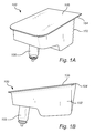
- Figs. 1A-B schematically illustrate a charging module 100 according to an embodiment of the invention.
- the charging module 100 comprises a housing 102 which in turn comprises a wireless charger unit 104 and a charging surface 106 for placing a device to be charged.
- the device to be charged may for example be a smartphone, a tablet computer and the like, or any other electronic device having wireless charging functionality.
- the charger unit 104 may also be fully or partially integrated with and located in the housing 102.
- the charging module 100 further comprises an electrical connection plug 108 fixedly connected to the housing 102 on a side of the housing opposite the charging surface 106.
- the plug 108 is here extending in a direction away from the charging surface 106.
- the charging module 100 is thus configured such that the charging surface 106 is horizontally aligned when in use. It is desirable with a horizontally aligned charging surface for preventing that the electronic device slides off the charging module.
- plug 108 is here illustrated as a conventional cigarette lighter type 12V plug, other types of electrical connectors may also be used, such as a USB plug.
- the housing 102 has a certain shape and size which can be selected based on the size of the control electronics required for controlling the charger unit 104 for embodiments where the control electronics is at least partially located in the housing.
- control electronics can be integrated in the charger unit 104, in which case the housing 102 can be made smaller.
- the charger unit 104 may also be releasably connected to the charging module 100. Thereby, the charger unit 104 can be easily replaced which may be advantageous if the charger unit 104 breaks or if different electronic devices requires different charging technologies.
- the shape of the housing 102 can be adapted to fit into a receiving recess to provide additional mechanical stability to the charging module 100.
- Fig. 2 schematically illustrates a charging module 200 where the size of the housing 102 is minimized.
- the housing and 102 and the charging unit 104 can be seen as one integrated unit.
- a slim charging module 200 is provided which weighs less and which may be stored more easily when not in use.
- Fig. 3 schematically illustrates a charging module 300 comprising a high friction material 302 arranged on the charging surface.
- the high friction material 302 may be arranged as a layer or film on the charger unit to form the charging surface 106.
- a high friction material is herein considered to be a material having a higher coefficient of static friction to a flat smooth material such as the glass or plastic typically forming the backside of an electronic device, than what a similar flat hard material would have.
- the high friction material may be a rubber material such as EPDM or any other rubber-like material known by the skilled person.
- the surface of the high friction material may also be structured to further prevent movement of an electronic device placed on the charging surface.
- the structures on the charging surface may for example be ribs, ridges or other protruding elements.
- Fig. 3 further illustrates that the charging module comprises a holding element 304 configured to hold an electronic device in place on the charging surface 106.
- the holding element 304 is here illustrated as a flexible element having a first portion 306 protruding in a direction from the charging surface 106 and a second portion 308, protruding from the first portion in parallel with the charging surface 106 and located at a distance from the charging surface 106 for clamping an electronic device to the charging surface 106.
- the holding element may equally well be arranged along one or more of the edges of the charger module.
- the flexibility of the holding element 304 acts to provide a downwards force on an electronic device placed between the charging surface 106 and the holding element 304.
- the flexibility of the holding element 304 also makes it possible to use the charging module 100 comprising the holding element 304 together with electronic devices of different thickness.
- the holding element may be provided with a high friction material of the lower side of the second portion 108, which is in contact with the electronic device when an electronic device is clamped by the holding element.
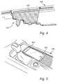
- Fig. 4 schematically illustrates a cross section of a part of a tunnel console 400 for a vehicle where a portable charging module 100 is arranged in a recess of the console.
- the charging surface 106 is recessed in relation to the outer surface of the console 400 which further acts to maintain an electronic device in place on the charging surface 106 due to the side walls formed by the console.
- Fig. 5 is a schematic top view of a tunnel console 400 in which a charging module 100 is placed, and where an electronic device in the form of a smartphone 502 is placed on the charging surface 106 and held in place by means of the holding element.
- the recess in which the charging module is placed may for example be a cup holder.
- the illustrated tunnel console is located adjacent to the driver seat of the vehicle and is thus easy to reach for a driver or front seat passenger.
- the described charging module may be arranged in many different ways.
Landscapes
- Engineering & Computer Science (AREA)
- Power Engineering (AREA)
- Computer Networks & Wireless Communication (AREA)
- Signal Processing (AREA)
- Charge And Discharge Circuits For Batteries Or The Like (AREA)
- Telephone Set Structure (AREA)
Abstract
Description
- The present invention relates to a wireless charger module for a vehicle and to a console for docking such a charger module.
- With the increasingly common use of battery powered electronic devices comes an increased need to provide efficient and convenient charging solutions.
- In particular, it is desirable to be able to conveniently charge an electronic device when traveling in a vehicle. For this purpose, wired charging solutions utilizing the cigarette lighter outlet in a vehicle have long been known. Moreover, with the introduction and increasing popularity of wireless charging solutions, a range of different wireless charging alternative have been presented.
- For example, it is know to provide a wireless charging module in a vehicle comprising a charging surface suitable for an electronic device such as a smartphone. However, smartphones and similar devices are made in many different sizes, which for example may lead to that the phone moves around on the charging surface or that the device does not fit due to it being too large.
- Accordingly, it is desirable to provide an improved wireless charger module for a vehicle to enable convenient wireless charging of different types of devices.
- In view of above-mentioned and other drawbacks of the prior art, it is an object of the present invention to provide an improved wireless charger module for use in a vehicle, and in particular to provide a charger module which advantageously may be located in a tunnel console of a vehicle.
- According a first aspect of the invention, there is provided a portable wireless charging module for a vehicle comprising: a housing comprising a wireless charger unit and a charging surface for placing a device to be charged; an electrical connection plug fixedly connected to the housing on a side of the housing opposite the charging surface; wherein the plug is extending in a direction away from the charging surface; and wherein the charging module is configured such that the charging surface is horizontally aligned when in use.
- The present invention is based on the realization that there is a need for a wireless charging module for a vehicle which is capable of charging a portable electronic device by means of inductive charging, i.e. wireless charging. By providing a charging module which comprises a horizontally aligned charging surface when in use, the charging module can be used to charge a wide range of electronic devices by placing the device on the charging surface. The charging module can be considered to be in use when connected to a corresponding receiving electrical connection socket such that the charger unit can be activated.
- An additional advantage of the charging module is that the fixedly connected, i.e. integrated, plug eliminates the need for cables and also provides mechanical support for the housing and the charging plate.
- According to one embodiment of the invention, the plug may be configured to be inserted in a in a substantially vertically aligned receiving electrical connection socket. Such a vertically aligned socket may for example be located in a tunnel console of a vehicle. The plug is thus arranged substantially perpendicularly to the horizontally aligned charging surface. However, it is also possible that the socket, and consequently the plug, is arranged at an angle in relation to a vertical plane.
- According to one embodiment of the invention the plug may be a cigarette lighter type plug. Since cigarette lighter type sockets are commonly available in vehicle, the charging module can be used in many different types of vehicles. However, the plug may also be of another type, such as USB and the like.
- According to one embodiment of the invention the plug may be protruding in a direction substantially perpendicular to a bottom surface of the housing portion. In particular, the bottom surface of the housing may be approximately parallel to the charging surface. A plug extending perpendicularly to the bottom surface of the housing is thus suitable for connecting to a vertically aligned socket.
- According to one embodiment of the invention the wireless charger may comprise the charging surface, and wherein the wireless charger is provided in the form of a charging plate releasably connected to the housing. By providing a releasable charging plate, the charging module can be made modular such that charging plates of different configurations can be used together with one and the same housing, making the charging modular to increase its possible applications.
- According to one embodiment of the invention the charging module may further comprise a high friction material arranged on the charging surface. The purpose of the high friction material is to prevent the device from moving around on the charging surface during use of the vehicle. A high friction material should be interpreted to include material having a friction which is sufficiently high to prevent movement of an electronic device during normal operation of the vehicle.
- According to one embodiment of the invention, the high friction material may be a rubber material, such as EPDM (ethylene propylene diene monomer) rubber or similar materials.
- According to one embodiment of the invention, the charging module may further comprise a holding element configured to hold an electronic device in place on the charging surface. The holding element may thus hold the electronic device in place also in case of more abrupt or powerful movement of the vehicle, which is important to improve the safety in a vehicle. In particular, the holing element reduces the risk of loose objects causing damage to occupants of the vehicle in case of an accident.
- According to one embodiment of the invention, the holding element may be a flexible element having a first portion protruding from the charging surface and a second portion, protruding from the first portion in parallel with and located at a distance from the charging surface to clamp an electronic device to the charging surface. The holding element can thus be described as an elongate L-shaped protruding from the charging module, where the electronic device can be inserted under the holding element to be kept in place. The holding element may be flexible, or spring loaded, such that a downward force acts on an electronic device arranged on the charging surface, thereby clamping the device to the charging surface. The holding element may also be provided with or made from a high friction material to further improve its ability to keep the electronic device in place.
- According to one embodiment of the invention, a size of the charging surface may be configured to correspond to a size of a predetermined electronic device, thereby providing the possibility to tailor the charging module to a specific device.
- According to one embodiment of the invention the housing may comprise a body, and the plug may be integrated in the body. Moreover, the body may comprise the control electronics for the wireless charger unit, and the size of the housing can thus be adapted based on the size of the control electronics.
- There is also provided a console for a vehicle comprising: a portable charging module according to any one of the above described embodiments, wherein the console comprises a recess and a cigarette lighter type socket located in the recess, and wherein the plug of the portable charging module is releasably connected to the socket.
- According to one embodiment of the invention the charging surface may be recessed in relation to an outer surface of the console, such that a compartment is formed where the electronic device can be placed. The side walls of the compartment will then prevent movement of the electronic device. The charging surface may also be aligned with the outer surface of the console. Thereby, the charging module can be made to blend into the overall appearance of the vehicle interior.
- In one embodiment of the invention, the recess in the console may be cup holder.
- According to one embodiment of the invention, the console may be a tunnel console configured to be located adjacent to a driver seat of a vehicle.
- Further features of, and advantages with, the present invention will become apparent when studying the appended claims and the following description. The skilled person realize that different features of the present invention may be combined to create embodiments other than those described in the following, without departing from the scope of the present invention.
- These and other aspects of the present invention will now be described in more detail, with reference to the appended drawings showing an example embodiment of the invention, wherein:
-
Figs. 1A-B schematically illustrate a charging module according to an embodiment of the invention; -
Fig. 2 schematically illustrates a charging module according to an embodiment of the invention; -
Fig. 3 schematically illustrates a charging module according to an embodiment of the invention; and -
Fig. 4 schematically illustrates a charging module according to an embodiment of the invention arranged in a vehicle; and -
Fig. 5 schematically illustrates a charging module according to an embodiment of the invention arranged in a vehicle. - In the present detailed description, various embodiments of the charging module according to the present invention are mainly described with reference to a charging module configured to be connected to a plug in a horizontally aligned console of a vehicle, such as a tunnel console located between the front seats of the vehicle. However, it should be noted that various embodiments of the invention are equally applicable for charging modules configure for use in other locations of a vehicle.
-
Figs. 1A-B schematically illustrate acharging module 100 according to an embodiment of the invention. Thecharging module 100 comprises ahousing 102 which in turn comprises awireless charger unit 104 and a chargingsurface 106 for placing a device to be charged. The device to be charged may for example be a smartphone, a tablet computer and the like, or any other electronic device having wireless charging functionality. Thecharger unit 104 may also be fully or partially integrated with and located in thehousing 102. - The
charging module 100 further comprises anelectrical connection plug 108 fixedly connected to thehousing 102 on a side of the housing opposite the chargingsurface 106. Theplug 108 is here extending in a direction away from the chargingsurface 106. Thecharging module 100 is thus configured such that the chargingsurface 106 is horizontally aligned when in use. It is desirable with a horizontally aligned charging surface for preventing that the electronic device slides off the charging module. - Even though the
plug 108 is here illustrated as a conventional cigarette lighter type 12V plug, other types of electrical connectors may also be used, such as a USB plug. - In
Figs. 1A-B , it can be seen that thehousing 102 has a certain shape and size which can be selected based on the size of the control electronics required for controlling thecharger unit 104 for embodiments where the control electronics is at least partially located in the housing. Alternatively, such control electronics can be integrated in thecharger unit 104, in which case thehousing 102 can be made smaller. Thecharger unit 104 may also be releasably connected to thecharging module 100. Thereby, thecharger unit 104 can be easily replaced which may be advantageous if thecharger unit 104 breaks or if different electronic devices requires different charging technologies. - Moreover, the shape of the
housing 102 can be adapted to fit into a receiving recess to provide additional mechanical stability to thecharging module 100. -
Fig. 2 schematically illustrates acharging module 200 where the size of thehousing 102 is minimized. In the illustrated embodiment, the housing and 102 and thecharging unit 104 can be seen as one integrated unit. Thereby, aslim charging module 200 is provided which weighs less and which may be stored more easily when not in use. -
Fig. 3 schematically illustrates acharging module 300 comprising ahigh friction material 302 arranged on the charging surface. Thehigh friction material 302 may be arranged as a layer or film on the charger unit to form the chargingsurface 106. - A high friction material is herein considered to be a material having a higher coefficient of static friction to a flat smooth material such as the glass or plastic typically forming the backside of an electronic device, than what a similar flat hard material would have. The high friction material may be a rubber material such as EPDM or any other rubber-like material known by the skilled person.
- The surface of the high friction material may also be structured to further prevent movement of an electronic device placed on the charging surface. The structures on the charging surface may for example be ribs, ridges or other protruding elements.
-
Fig. 3 further illustrates that the charging module comprises a holdingelement 304 configured to hold an electronic device in place on the chargingsurface 106. The holdingelement 304 is here illustrated as a flexible element having afirst portion 306 protruding in a direction from the chargingsurface 106 and asecond portion 308, protruding from the first portion in parallel with the chargingsurface 106 and located at a distance from the chargingsurface 106 for clamping an electronic device to the chargingsurface 106. - Even though the holding element is illustrated as being located at a short edge of the charging module, the holding element may equally well be arranged along one or more of the edges of the charger module. The flexibility of the holding
element 304 acts to provide a downwards force on an electronic device placed between the chargingsurface 106 and the holdingelement 304. The flexibility of the holdingelement 304 also makes it possible to use thecharging module 100 comprising the holdingelement 304 together with electronic devices of different thickness. - To further improve the ability to maintain the electronic device in the desired position on the charging
surface 106, the holding element may be provided with a high friction material of the lower side of thesecond portion 108, which is in contact with the electronic device when an electronic device is clamped by the holding element. - The skilled person readily realizes that a wide range of different mechanical configurations are possible to achieve the desired functionality of a holding element.
-
Fig. 4 schematically illustrates a cross section of a part of atunnel console 400 for a vehicle where aportable charging module 100 is arranged in a recess of the console. Here, it can be seen that the chargingsurface 106 is recessed in relation to the outer surface of theconsole 400 which further acts to maintain an electronic device in place on the chargingsurface 106 due to the side walls formed by the console. -
Fig. 5 is a schematic top view of atunnel console 400 in which acharging module 100 is placed, and where an electronic device in the form of asmartphone 502 is placed on the chargingsurface 106 and held in place by means of the holding element. The recess in which the charging module is placed may for example be a cup holder. The illustrated tunnel console is located adjacent to the driver seat of the vehicle and is thus easy to reach for a driver or front seat passenger. However, the described charging module may be arranged in many different ways. - Even though the invention has been described with reference to specific exemplifying embodiments thereof, many different alterations, modifications and the like will become apparent for those skilled in the art. Also, it should be noted that parts of the charging module may be omitted, interchanged or arranged in various ways, the charging module yet being able to perform the functionality of the present invention.
- Additionally, variations to the disclosed embodiments can be understood and effected by the skilled person in practicing the claimed invention, from a study of the drawings, the disclosure, and the appended claims. In the claims, the word "comprising" does not exclude other elements or steps, and the indefinite article "a" or "an" does not exclude a plurality. The mere fact that certain measures are recited in mutually different dependent claims does not indicate that a combination of these measures cannot be used to advantage.
Claims (15)
- A portable wireless charging module (100, 200, 300) for a vehicle comprising:a housing (102) comprising a wireless charger unit (104) and a charging surface (106) for placing a device to be charged;an electrical connection plug (108) fixedly connected to the housing on a side of the housing opposite the charging surface;wherein the plug is extending in a direction away from the charging surface; andwherein the charging module is configured such that the charging surface is horizontally aligned when in use.
- The charging module according to claim 1, where the plug is configured to be inserted in a in a substantially vertically aligned receiving electrical connection socket.
- The charging module according to claim 1 or 2, wherein the plug is a cigarette lighter type plug.
- The charging module according to any one of the preceding claims, wherein the plug is protruding in a direction substantially perpendicular to a bottom surface of the housing portion.
- The charging module according to any one of the preceding claims, wherein the wireless charger comprises the charging surface, and wherein the wireless charger is provided in the form of a charging plate releasably connected to the housing.
- The charging module according to any one of the preceding claims, further comprising a high friction material (302) arranged on the charging surface.
- The charging module according to claim 6, wherein the high friction material is a rubber material.
- The charging module according to any one of the preceding claims, further comprising a holding element (304) configured to hold an electronic device in place on the charging surface.
- The charging module according to claim 8, wherein the holding element is a flexible element having a first portion (306) protruding in a direction from the charging surface and a second portion (308), protruding from the first portion in parallel with and located at a distance from the charging surface for clamping an electronic device to the charging surface.
- The charging module according to any one of the preceding claims, wherein a size of the charging surface is configured to correspond to a size of a predetermined electronic device.
- The charging module according to any one of the preceding claims, wherein the housing comprises a body, and wherein the plug is integrated in the body.
- A console (400) for a vehicle comprising:a portable charging module (100) according to any one of the preceding claims, wherein the console comprises a recess and a cigarette lighter type socket located in the recess, and wherein the plug of the portable charging module is releasably connected to the socket.
- The console according to claim 12, wherein the charging surface is recessed in relation to an outer surface of the console.
- The console according to claim 12 or 13, wherein the recess in the console is a cup holder.
- The console according to any one of claims 12 to 14, wherein the console is a tunnel console configured to be located adjacent to a driver seat of a vehicle.
Priority Applications (1)
| Application Number | Priority Date | Filing Date | Title |
|---|---|---|---|
| EP16177779.2A EP3267550B1 (en) | 2016-07-04 | 2016-07-04 | Wireless charger module for a vehicle |
Applications Claiming Priority (1)
| Application Number | Priority Date | Filing Date | Title |
|---|---|---|---|
| EP16177779.2A EP3267550B1 (en) | 2016-07-04 | 2016-07-04 | Wireless charger module for a vehicle |
Publications (2)
| Publication Number | Publication Date |
|---|---|
| EP3267550A1 true EP3267550A1 (en) | 2018-01-10 |
| EP3267550B1 EP3267550B1 (en) | 2024-04-10 |
Family
ID=56360226
Family Applications (1)
| Application Number | Title | Priority Date | Filing Date |
|---|---|---|---|
| EP16177779.2A Active EP3267550B1 (en) | 2016-07-04 | 2016-07-04 | Wireless charger module for a vehicle |
Country Status (1)
| Country | Link |
|---|---|
| EP (1) | EP3267550B1 (en) |
Cited By (1)
| Publication number | Priority date | Publication date | Assignee | Title |
|---|---|---|---|---|
| WO2023285638A1 (en) * | 2021-07-16 | 2023-01-19 | Globaltronics Gmbh & Co. Kg | Apparatus for placing an object |
Citations (4)
| Publication number | Priority date | Publication date | Assignee | Title |
|---|---|---|---|---|
| CN2765366Y (en) * | 2005-01-24 | 2006-03-15 | 陈波 | A charger for vehicle |
| CN202978382U (en) * | 2012-12-19 | 2013-06-05 | 浙江中呼科技有限公司 | AC-DC (Alternating Current-Direct Current) multipurpose wireless charger |
| US20130260610A1 (en) * | 2012-04-03 | 2013-10-03 | Global Ip Holdings, Llc | Automotive vehicle interior plastic part having a support surface capable of wirelessly supplying electrical power |
| US20130257147A1 (en) * | 2012-04-03 | 2013-10-03 | Global Ip Holdings, Llc | Assembly capable of simultaneously supporting and wirelessly supplying electrical power to a portable electronic device within a passenger compartment of a vehicle |
Family Cites Families (2)
| Publication number | Priority date | Publication date | Assignee | Title |
|---|---|---|---|---|
| US20060278788A1 (en) * | 2005-05-27 | 2006-12-14 | Eagle Fan | Fixing seat |
| CN204316164U (en) * | 2015-01-08 | 2015-05-06 | 深圳市德泰能源有限公司 | A kind of vehicle carried mobile phone wireless charging device |
-
2016
- 2016-07-04 EP EP16177779.2A patent/EP3267550B1/en active Active
Patent Citations (4)
| Publication number | Priority date | Publication date | Assignee | Title |
|---|---|---|---|---|
| CN2765366Y (en) * | 2005-01-24 | 2006-03-15 | 陈波 | A charger for vehicle |
| US20130260610A1 (en) * | 2012-04-03 | 2013-10-03 | Global Ip Holdings, Llc | Automotive vehicle interior plastic part having a support surface capable of wirelessly supplying electrical power |
| US20130257147A1 (en) * | 2012-04-03 | 2013-10-03 | Global Ip Holdings, Llc | Assembly capable of simultaneously supporting and wirelessly supplying electrical power to a portable electronic device within a passenger compartment of a vehicle |
| CN202978382U (en) * | 2012-12-19 | 2013-06-05 | 浙江中呼科技有限公司 | AC-DC (Alternating Current-Direct Current) multipurpose wireless charger |
Cited By (1)
| Publication number | Priority date | Publication date | Assignee | Title |
|---|---|---|---|---|
| WO2023285638A1 (en) * | 2021-07-16 | 2023-01-19 | Globaltronics Gmbh & Co. Kg | Apparatus for placing an object |
Also Published As
| Publication number | Publication date |
|---|---|
| EP3267550B1 (en) | 2024-04-10 |
Similar Documents
| Publication | Publication Date | Title |
|---|---|---|
| US9821723B2 (en) | Height adjustable holder for mobile device | |
| CN105765288B (en) | Height-adjustable supports for mobile equipment | |
| US8922354B2 (en) | External haptic generator for portable electronic devices | |
| US9096177B2 (en) | Apparatus for securing a rechargeable electronic device with respect to a surface of a wireless battery charging apparatus of a vehicle | |
| CN107074158B (en) | Mechanical support for loading mobile equipment in vehicle | |
| JP6169594B2 (en) | Power transmitter device for inductively supplying power to mobile devices | |
| CN206624144U (en) | For accommodating the storage tank of at least one mobile terminal | |
| US9397718B2 (en) | Mobile telephone holding device | |
| EP2746109B1 (en) | A phone holder | |
| CN105916738A (en) | System for charging and securing an electronic device in a vehicle | |
| CN105599645B (en) | For keeping the seat covering of object | |
| US9446720B1 (en) | Adjustable bracket for mounting an electronic media device in a vehicle | |
| CN106864384B (en) | Vehicle's smartphone holding device | |
| EP2979930A1 (en) | Wireless charging device for vehicles | |
| CN107487273B (en) | Vehicle-mounted wireless charging device and vehicle | |
| CN103840517B (en) | Wireless charging fixing device of terminal | |
| EP3267550B1 (en) | Wireless charger module for a vehicle | |
| CN110356333A (en) | Lid arrangement | |
| CN102310834B (en) | Connecting device and method for air bag module | |
| CN106165205B (en) | Electrical connection device and electrical contact device | |
| CN113401064B (en) | Storage structure for vehicle | |
| CN105337332A (en) | Vehicle-mounted wireless charging device | |
| CN207504944U (en) | It is a kind of can wireless charging mobile phone support | |
| KR20130071039A (en) | Supporter for electronic equipment in vehicle | |
| JP2019077259A (en) | Interior trim |
Legal Events
| Date | Code | Title | Description |
|---|---|---|---|
| PUAI | Public reference made under article 153(3) epc to a published international application that has entered the european phase |
Free format text: ORIGINAL CODE: 0009012 |
|
| STAA | Information on the status of an ep patent application or granted ep patent |
Free format text: STATUS: THE APPLICATION HAS BEEN PUBLISHED |
|
| AK | Designated contracting states |
Kind code of ref document: A1 Designated state(s): AL AT BE BG CH CY CZ DE DK EE ES FI FR GB GR HR HU IE IS IT LI LT LU LV MC MK MT NL NO PL PT RO RS SE SI SK SM TR |
|
| AX | Request for extension of the european patent |
Extension state: BA ME |
|
| STAA | Information on the status of an ep patent application or granted ep patent |
Free format text: STATUS: REQUEST FOR EXAMINATION WAS MADE |
|
| 17P | Request for examination filed |
Effective date: 20180710 |
|
| RBV | Designated contracting states (corrected) |
Designated state(s): AL AT BE BG CH CY CZ DE DK EE ES FI FR GB GR HR HU IE IS IT LI LT LU LV MC MK MT NL NO PL PT RO RS SE SI SK SM TR |
|
| STAA | Information on the status of an ep patent application or granted ep patent |
Free format text: STATUS: EXAMINATION IS IN PROGRESS |
|
| 17Q | First examination report despatched |
Effective date: 20210618 |
|
| GRAP | Despatch of communication of intention to grant a patent |
Free format text: ORIGINAL CODE: EPIDOSNIGR1 |
|
| STAA | Information on the status of an ep patent application or granted ep patent |
Free format text: STATUS: GRANT OF PATENT IS INTENDED |
|
| RIC1 | Information provided on ipc code assigned before grant |
Ipc: H01R 31/06 20060101ALN20231201BHEP Ipc: H01R 13/66 20060101ALN20231201BHEP Ipc: H04M 1/04 20060101ALI20231201BHEP Ipc: H02J 50/90 20160101ALI20231201BHEP Ipc: H02J 50/10 20160101ALI20231201BHEP Ipc: H02J 7/34 20060101ALI20231201BHEP Ipc: H02J 7/02 20160101ALI20231201BHEP Ipc: H02J 7/00 20060101AFI20231201BHEP |
|
| RIC1 | Information provided on ipc code assigned before grant |
Ipc: H01R 31/06 20060101ALN20231212BHEP Ipc: H01R 13/66 20060101ALN20231212BHEP Ipc: H04M 1/04 20060101ALI20231212BHEP Ipc: H02J 50/90 20160101ALI20231212BHEP Ipc: H02J 50/10 20160101ALI20231212BHEP Ipc: H02J 7/34 20060101ALI20231212BHEP Ipc: H02J 7/02 20160101ALI20231212BHEP Ipc: H02J 7/00 20060101AFI20231212BHEP |
|
| INTG | Intention to grant announced |
Effective date: 20240104 |
|
| GRAS | Grant fee paid |
Free format text: ORIGINAL CODE: EPIDOSNIGR3 |
|
| GRAA | (expected) grant |
Free format text: ORIGINAL CODE: 0009210 |
|
| STAA | Information on the status of an ep patent application or granted ep patent |
Free format text: STATUS: THE PATENT HAS BEEN GRANTED |
|
| AK | Designated contracting states |
Kind code of ref document: B1 Designated state(s): AL AT BE BG CH CY CZ DE DK EE ES FI FR GB GR HR HU IE IS IT LI LT LU LV MC MK MT NL NO PL PT RO RS SE SI SK SM TR |
|
| REG | Reference to a national code |
Ref country code: GB Ref legal event code: FG4D |
|
| REG | Reference to a national code |
Ref country code: CH Ref legal event code: EP |
|
| REG | Reference to a national code |
Ref country code: DE Ref legal event code: R096 Ref document number: 602016086796 Country of ref document: DE |
|
| REG | Reference to a national code |
Ref country code: DE Ref legal event code: R081 Ref document number: 602016086796 Country of ref document: DE Owner name: POLESTAR PERFORMANCE AB, SE Free format text: FORMER OWNER: VOLVO CAR CORPORATION, GOETEBORG, SE |
|
| REG | Reference to a national code |
Ref country code: IE Ref legal event code: FG4D |
|
| RAP2 | Party data changed (patent owner data changed or rights of a patent transferred) |
Owner name: POLESTAR PERFORMANCE AB |
|
| REG | Reference to a national code |
Ref country code: SE Ref legal event code: TRGR |
|
| REG | Reference to a national code |
Ref country code: LT Ref legal event code: MG9D |
|
| REG | Reference to a national code |
Ref country code: NL Ref legal event code: MP Effective date: 20240410 |
|
| REG | Reference to a national code |
Ref country code: AT Ref legal event code: MK05 Ref document number: 1675925 Country of ref document: AT Kind code of ref document: T Effective date: 20240410 |
|
| PG25 | Lapsed in a contracting state [announced via postgrant information from national office to epo] |
Ref country code: NL Free format text: LAPSE BECAUSE OF FAILURE TO SUBMIT A TRANSLATION OF THE DESCRIPTION OR TO PAY THE FEE WITHIN THE PRESCRIBED TIME-LIMIT Effective date: 20240410 |
|
| PG25 | Lapsed in a contracting state [announced via postgrant information from national office to epo] |
Ref country code: NL Free format text: LAPSE BECAUSE OF FAILURE TO SUBMIT A TRANSLATION OF THE DESCRIPTION OR TO PAY THE FEE WITHIN THE PRESCRIBED TIME-LIMIT Effective date: 20240410 |
|
| PG25 | Lapsed in a contracting state [announced via postgrant information from national office to epo] |
Ref country code: IS Free format text: LAPSE BECAUSE OF FAILURE TO SUBMIT A TRANSLATION OF THE DESCRIPTION OR TO PAY THE FEE WITHIN THE PRESCRIBED TIME-LIMIT Effective date: 20240810 |
|
| PG25 | Lapsed in a contracting state [announced via postgrant information from national office to epo] |
Ref country code: BG Free format text: LAPSE BECAUSE OF FAILURE TO SUBMIT A TRANSLATION OF THE DESCRIPTION OR TO PAY THE FEE WITHIN THE PRESCRIBED TIME-LIMIT Effective date: 20240410 |
|
| PG25 | Lapsed in a contracting state [announced via postgrant information from national office to epo] |
Ref country code: FI Free format text: LAPSE BECAUSE OF FAILURE TO SUBMIT A TRANSLATION OF THE DESCRIPTION OR TO PAY THE FEE WITHIN THE PRESCRIBED TIME-LIMIT Effective date: 20240410 Ref country code: HR Free format text: LAPSE BECAUSE OF FAILURE TO SUBMIT A TRANSLATION OF THE DESCRIPTION OR TO PAY THE FEE WITHIN THE PRESCRIBED TIME-LIMIT Effective date: 20240410 |
|
| PG25 | Lapsed in a contracting state [announced via postgrant information from national office to epo] |
Ref country code: GR Free format text: LAPSE BECAUSE OF FAILURE TO SUBMIT A TRANSLATION OF THE DESCRIPTION OR TO PAY THE FEE WITHIN THE PRESCRIBED TIME-LIMIT Effective date: 20240711 |
|
| PG25 | Lapsed in a contracting state [announced via postgrant information from national office to epo] |
Ref country code: PT Free format text: LAPSE BECAUSE OF FAILURE TO SUBMIT A TRANSLATION OF THE DESCRIPTION OR TO PAY THE FEE WITHIN THE PRESCRIBED TIME-LIMIT Effective date: 20240812 |
|
| PG25 | Lapsed in a contracting state [announced via postgrant information from national office to epo] |
Ref country code: ES Free format text: LAPSE BECAUSE OF FAILURE TO SUBMIT A TRANSLATION OF THE DESCRIPTION OR TO PAY THE FEE WITHIN THE PRESCRIBED TIME-LIMIT Effective date: 20240410 |
|
| PG25 | Lapsed in a contracting state [announced via postgrant information from national office to epo] |
Ref country code: AT Free format text: LAPSE BECAUSE OF FAILURE TO SUBMIT A TRANSLATION OF THE DESCRIPTION OR TO PAY THE FEE WITHIN THE PRESCRIBED TIME-LIMIT Effective date: 20240410 |
|
| PG25 | Lapsed in a contracting state [announced via postgrant information from national office to epo] |
Ref country code: PL Free format text: LAPSE BECAUSE OF FAILURE TO SUBMIT A TRANSLATION OF THE DESCRIPTION OR TO PAY THE FEE WITHIN THE PRESCRIBED TIME-LIMIT Effective date: 20240410 |
|
| PG25 | Lapsed in a contracting state [announced via postgrant information from national office to epo] |
Ref country code: LV Free format text: LAPSE BECAUSE OF FAILURE TO SUBMIT A TRANSLATION OF THE DESCRIPTION OR TO PAY THE FEE WITHIN THE PRESCRIBED TIME-LIMIT Effective date: 20240410 |
|
| PG25 | Lapsed in a contracting state [announced via postgrant information from national office to epo] |
Ref country code: PT Free format text: LAPSE BECAUSE OF FAILURE TO SUBMIT A TRANSLATION OF THE DESCRIPTION OR TO PAY THE FEE WITHIN THE PRESCRIBED TIME-LIMIT Effective date: 20240812 Ref country code: PL Free format text: LAPSE BECAUSE OF FAILURE TO SUBMIT A TRANSLATION OF THE DESCRIPTION OR TO PAY THE FEE WITHIN THE PRESCRIBED TIME-LIMIT Effective date: 20240410 Ref country code: NO Free format text: LAPSE BECAUSE OF FAILURE TO SUBMIT A TRANSLATION OF THE DESCRIPTION OR TO PAY THE FEE WITHIN THE PRESCRIBED TIME-LIMIT Effective date: 20240710 Ref country code: LV Free format text: LAPSE BECAUSE OF FAILURE TO SUBMIT A TRANSLATION OF THE DESCRIPTION OR TO PAY THE FEE WITHIN THE PRESCRIBED TIME-LIMIT Effective date: 20240410 Ref country code: IS Free format text: LAPSE BECAUSE OF FAILURE TO SUBMIT A TRANSLATION OF THE DESCRIPTION OR TO PAY THE FEE WITHIN THE PRESCRIBED TIME-LIMIT Effective date: 20240810 Ref country code: HR Free format text: LAPSE BECAUSE OF FAILURE TO SUBMIT A TRANSLATION OF THE DESCRIPTION OR TO PAY THE FEE WITHIN THE PRESCRIBED TIME-LIMIT Effective date: 20240410 Ref country code: GR Free format text: LAPSE BECAUSE OF FAILURE TO SUBMIT A TRANSLATION OF THE DESCRIPTION OR TO PAY THE FEE WITHIN THE PRESCRIBED TIME-LIMIT Effective date: 20240711 Ref country code: FI Free format text: LAPSE BECAUSE OF FAILURE TO SUBMIT A TRANSLATION OF THE DESCRIPTION OR TO PAY THE FEE WITHIN THE PRESCRIBED TIME-LIMIT Effective date: 20240410 Ref country code: ES Free format text: LAPSE BECAUSE OF FAILURE TO SUBMIT A TRANSLATION OF THE DESCRIPTION OR TO PAY THE FEE WITHIN THE PRESCRIBED TIME-LIMIT Effective date: 20240410 Ref country code: BG Free format text: LAPSE BECAUSE OF FAILURE TO SUBMIT A TRANSLATION OF THE DESCRIPTION OR TO PAY THE FEE WITHIN THE PRESCRIBED TIME-LIMIT Effective date: 20240410 Ref country code: AT Free format text: LAPSE BECAUSE OF FAILURE TO SUBMIT A TRANSLATION OF THE DESCRIPTION OR TO PAY THE FEE WITHIN THE PRESCRIBED TIME-LIMIT Effective date: 20240410 Ref country code: RS Free format text: LAPSE BECAUSE OF FAILURE TO SUBMIT A TRANSLATION OF THE DESCRIPTION OR TO PAY THE FEE WITHIN THE PRESCRIBED TIME-LIMIT Effective date: 20240710 |
|
| REG | Reference to a national code |
Ref country code: DE Ref legal event code: R097 Ref document number: 602016086796 Country of ref document: DE |
|
| PG25 | Lapsed in a contracting state [announced via postgrant information from national office to epo] |
Ref country code: DK Free format text: LAPSE BECAUSE OF FAILURE TO SUBMIT A TRANSLATION OF THE DESCRIPTION OR TO PAY THE FEE WITHIN THE PRESCRIBED TIME-LIMIT Effective date: 20240410 |
|
| PG25 | Lapsed in a contracting state [announced via postgrant information from national office to epo] |
Ref country code: EE Free format text: LAPSE BECAUSE OF FAILURE TO SUBMIT A TRANSLATION OF THE DESCRIPTION OR TO PAY THE FEE WITHIN THE PRESCRIBED TIME-LIMIT Effective date: 20240410 |
|
| PG25 | Lapsed in a contracting state [announced via postgrant information from national office to epo] |
Ref country code: CZ Free format text: LAPSE BECAUSE OF FAILURE TO SUBMIT A TRANSLATION OF THE DESCRIPTION OR TO PAY THE FEE WITHIN THE PRESCRIBED TIME-LIMIT Effective date: 20240410 |
|
| PG25 | Lapsed in a contracting state [announced via postgrant information from national office to epo] |
Ref country code: SK Free format text: LAPSE BECAUSE OF FAILURE TO SUBMIT A TRANSLATION OF THE DESCRIPTION OR TO PAY THE FEE WITHIN THE PRESCRIBED TIME-LIMIT Effective date: 20240410 Ref country code: RO Free format text: LAPSE BECAUSE OF FAILURE TO SUBMIT A TRANSLATION OF THE DESCRIPTION OR TO PAY THE FEE WITHIN THE PRESCRIBED TIME-LIMIT Effective date: 20240410 |
|
| PG25 | Lapsed in a contracting state [announced via postgrant information from national office to epo] |
Ref country code: SM Free format text: LAPSE BECAUSE OF FAILURE TO SUBMIT A TRANSLATION OF THE DESCRIPTION OR TO PAY THE FEE WITHIN THE PRESCRIBED TIME-LIMIT Effective date: 20240410 |
|
| PG25 | Lapsed in a contracting state [announced via postgrant information from national office to epo] |
Ref country code: SM Free format text: LAPSE BECAUSE OF FAILURE TO SUBMIT A TRANSLATION OF THE DESCRIPTION OR TO PAY THE FEE WITHIN THE PRESCRIBED TIME-LIMIT Effective date: 20240410 Ref country code: SK Free format text: LAPSE BECAUSE OF FAILURE TO SUBMIT A TRANSLATION OF THE DESCRIPTION OR TO PAY THE FEE WITHIN THE PRESCRIBED TIME-LIMIT Effective date: 20240410 Ref country code: RO Free format text: LAPSE BECAUSE OF FAILURE TO SUBMIT A TRANSLATION OF THE DESCRIPTION OR TO PAY THE FEE WITHIN THE PRESCRIBED TIME-LIMIT Effective date: 20240410 Ref country code: EE Free format text: LAPSE BECAUSE OF FAILURE TO SUBMIT A TRANSLATION OF THE DESCRIPTION OR TO PAY THE FEE WITHIN THE PRESCRIBED TIME-LIMIT Effective date: 20240410 Ref country code: DK Free format text: LAPSE BECAUSE OF FAILURE TO SUBMIT A TRANSLATION OF THE DESCRIPTION OR TO PAY THE FEE WITHIN THE PRESCRIBED TIME-LIMIT Effective date: 20240410 Ref country code: CZ Free format text: LAPSE BECAUSE OF FAILURE TO SUBMIT A TRANSLATION OF THE DESCRIPTION OR TO PAY THE FEE WITHIN THE PRESCRIBED TIME-LIMIT Effective date: 20240410 |
|
| PG25 | Lapsed in a contracting state [announced via postgrant information from national office to epo] |
Ref country code: MC Free format text: LAPSE BECAUSE OF FAILURE TO SUBMIT A TRANSLATION OF THE DESCRIPTION OR TO PAY THE FEE WITHIN THE PRESCRIBED TIME-LIMIT Effective date: 20240410 Ref country code: IT Free format text: LAPSE BECAUSE OF FAILURE TO SUBMIT A TRANSLATION OF THE DESCRIPTION OR TO PAY THE FEE WITHIN THE PRESCRIBED TIME-LIMIT Effective date: 20240410 |
|
| PLBE | No opposition filed within time limit |
Free format text: ORIGINAL CODE: 0009261 |
|
| STAA | Information on the status of an ep patent application or granted ep patent |
Free format text: STATUS: NO OPPOSITION FILED WITHIN TIME LIMIT |
|
| REG | Reference to a national code |
Ref country code: CH Ref legal event code: PL |
|
| PG25 | Lapsed in a contracting state [announced via postgrant information from national office to epo] |
Ref country code: LU Free format text: LAPSE BECAUSE OF NON-PAYMENT OF DUE FEES Effective date: 20240704 |
|
| 26N | No opposition filed |
Effective date: 20250113 |
|
| PG25 | Lapsed in a contracting state [announced via postgrant information from national office to epo] |
Ref country code: LU Free format text: LAPSE BECAUSE OF NON-PAYMENT OF DUE FEES Effective date: 20240704 |
|
| PG25 | Lapsed in a contracting state [announced via postgrant information from national office to epo] |
Ref country code: CH Free format text: LAPSE BECAUSE OF NON-PAYMENT OF DUE FEES Effective date: 20240731 Ref country code: SI Free format text: LAPSE BECAUSE OF FAILURE TO SUBMIT A TRANSLATION OF THE DESCRIPTION OR TO PAY THE FEE WITHIN THE PRESCRIBED TIME-LIMIT Effective date: 20240410 Ref country code: BE Free format text: LAPSE BECAUSE OF NON-PAYMENT OF DUE FEES Effective date: 20240731 |
|
| REG | Reference to a national code |
Ref country code: BE Ref legal event code: MM Effective date: 20240731 |
|
| PGFP | Annual fee paid to national office [announced via postgrant information from national office to epo] |
Ref country code: GB Payment date: 20250609 Year of fee payment: 10 |
|
| PGFP | Annual fee paid to national office [announced via postgrant information from national office to epo] |
Ref country code: FR Payment date: 20250521 Year of fee payment: 10 |
|
| PG25 | Lapsed in a contracting state [announced via postgrant information from national office to epo] |
Ref country code: IE Free format text: LAPSE BECAUSE OF NON-PAYMENT OF DUE FEES Effective date: 20240704 |
|
| PGFP | Annual fee paid to national office [announced via postgrant information from national office to epo] |
Ref country code: SE Payment date: 20250520 Year of fee payment: 10 |
|
| PGFP | Annual fee paid to national office [announced via postgrant information from national office to epo] |
Ref country code: DE Payment date: 20250618 Year of fee payment: 10 |
|
| PG25 | Lapsed in a contracting state [announced via postgrant information from national office to epo] |
Ref country code: CY Free format text: LAPSE BECAUSE OF FAILURE TO SUBMIT A TRANSLATION OF THE DESCRIPTION OR TO PAY THE FEE WITHIN THE PRESCRIBED TIME-LIMIT; INVALID AB INITIO Effective date: 20160704 |
|
| PG25 | Lapsed in a contracting state [announced via postgrant information from national office to epo] |
Ref country code: HU Free format text: LAPSE BECAUSE OF FAILURE TO SUBMIT A TRANSLATION OF THE DESCRIPTION OR TO PAY THE FEE WITHIN THE PRESCRIBED TIME-LIMIT; INVALID AB INITIO Effective date: 20160704 |