EP3267357A1 - Energizing scanners - Google Patents
Energizing scanners Download PDFInfo
- Publication number
- EP3267357A1 EP3267357A1 EP17179421.7A EP17179421A EP3267357A1 EP 3267357 A1 EP3267357 A1 EP 3267357A1 EP 17179421 A EP17179421 A EP 17179421A EP 3267357 A1 EP3267357 A1 EP 3267357A1
- Authority
- EP
- European Patent Office
- Prior art keywords
- scanner
- operable
- scanning
- supercapacitor
- data
- Prior art date
- Legal status (The legal status is an assumption and is not a legal conclusion. Google has not performed a legal analysis and makes no representation as to the accuracy of the status listed.)
- Granted
Links
Images




Classifications
-
- G—PHYSICS
- G06—COMPUTING OR CALCULATING; COUNTING
- G06K—GRAPHICAL DATA READING; PRESENTATION OF DATA; RECORD CARRIERS; HANDLING RECORD CARRIERS
- G06K7/00—Methods or arrangements for sensing record carriers, e.g. for reading patterns
- G06K7/10—Methods or arrangements for sensing record carriers, e.g. for reading patterns by electromagnetic radiation, e.g. optical sensing; by corpuscular radiation
- G06K7/10544—Methods or arrangements for sensing record carriers, e.g. for reading patterns by electromagnetic radiation, e.g. optical sensing; by corpuscular radiation by scanning of the records by radiation in the optical part of the electromagnetic spectrum
- G06K7/10821—Methods or arrangements for sensing record carriers, e.g. for reading patterns by electromagnetic radiation, e.g. optical sensing; by corpuscular radiation by scanning of the records by radiation in the optical part of the electromagnetic spectrum further details of bar or optical code scanning devices
- G06K7/10881—Methods or arrangements for sensing record carriers, e.g. for reading patterns by electromagnetic radiation, e.g. optical sensing; by corpuscular radiation by scanning of the records by radiation in the optical part of the electromagnetic spectrum further details of bar or optical code scanning devices constructional details of hand-held scanners
- G06K7/10891—Methods or arrangements for sensing record carriers, e.g. for reading patterns by electromagnetic radiation, e.g. optical sensing; by corpuscular radiation by scanning of the records by radiation in the optical part of the electromagnetic spectrum further details of bar or optical code scanning devices constructional details of hand-held scanners the scanner to be worn on a finger or on a wrist
-
- G—PHYSICS
- G06—COMPUTING OR CALCULATING; COUNTING
- G06F—ELECTRIC DIGITAL DATA PROCESSING
- G06F1/00—Details not covered by groups G06F3/00 - G06F13/00 and G06F21/00
- G06F1/16—Constructional details or arrangements
- G06F1/1613—Constructional details or arrangements for portable computers
- G06F1/163—Wearable computers, e.g. on a belt
-
- G—PHYSICS
- G06—COMPUTING OR CALCULATING; COUNTING
- G06K—GRAPHICAL DATA READING; PRESENTATION OF DATA; RECORD CARRIERS; HANDLING RECORD CARRIERS
- G06K7/00—Methods or arrangements for sensing record carriers, e.g. for reading patterns
- G06K7/10—Methods or arrangements for sensing record carriers, e.g. for reading patterns by electromagnetic radiation, e.g. optical sensing; by corpuscular radiation
-
- G—PHYSICS
- G06—COMPUTING OR CALCULATING; COUNTING
- G06K—GRAPHICAL DATA READING; PRESENTATION OF DATA; RECORD CARRIERS; HANDLING RECORD CARRIERS
- G06K7/00—Methods or arrangements for sensing record carriers, e.g. for reading patterns
- G06K7/10—Methods or arrangements for sensing record carriers, e.g. for reading patterns by electromagnetic radiation, e.g. optical sensing; by corpuscular radiation
- G06K7/10009—Methods or arrangements for sensing record carriers, e.g. for reading patterns by electromagnetic radiation, e.g. optical sensing; by corpuscular radiation sensing by radiation using wavelengths larger than 0.1 mm, e.g. radio-waves or microwaves
- G06K7/10198—Methods or arrangements for sensing record carriers, e.g. for reading patterns by electromagnetic radiation, e.g. optical sensing; by corpuscular radiation sensing by radiation using wavelengths larger than 0.1 mm, e.g. radio-waves or microwaves setting parameters for the interrogator, e.g. programming parameters and operating modes
- G06K7/10207—Methods or arrangements for sensing record carriers, e.g. for reading patterns by electromagnetic radiation, e.g. optical sensing; by corpuscular radiation sensing by radiation using wavelengths larger than 0.1 mm, e.g. radio-waves or microwaves setting parameters for the interrogator, e.g. programming parameters and operating modes parameter settings related to power consumption of the interrogator
-
- G—PHYSICS
- G06—COMPUTING OR CALCULATING; COUNTING
- G06K—GRAPHICAL DATA READING; PRESENTATION OF DATA; RECORD CARRIERS; HANDLING RECORD CARRIERS
- G06K7/00—Methods or arrangements for sensing record carriers, e.g. for reading patterns
- G06K7/10—Methods or arrangements for sensing record carriers, e.g. for reading patterns by electromagnetic radiation, e.g. optical sensing; by corpuscular radiation
- G06K7/10009—Methods or arrangements for sensing record carriers, e.g. for reading patterns by electromagnetic radiation, e.g. optical sensing; by corpuscular radiation sensing by radiation using wavelengths larger than 0.1 mm, e.g. radio-waves or microwaves
- G06K7/10297—Methods or arrangements for sensing record carriers, e.g. for reading patterns by electromagnetic radiation, e.g. optical sensing; by corpuscular radiation sensing by radiation using wavelengths larger than 0.1 mm, e.g. radio-waves or microwaves arrangements for handling protocols designed for non-contact record carriers such as RFIDs NFCs, e.g. ISO/IEC 14443 and 18092
-
- G—PHYSICS
- G06—COMPUTING OR CALCULATING; COUNTING
- G06K—GRAPHICAL DATA READING; PRESENTATION OF DATA; RECORD CARRIERS; HANDLING RECORD CARRIERS
- G06K7/00—Methods or arrangements for sensing record carriers, e.g. for reading patterns
- G06K7/10—Methods or arrangements for sensing record carriers, e.g. for reading patterns by electromagnetic radiation, e.g. optical sensing; by corpuscular radiation
- G06K7/14—Methods or arrangements for sensing record carriers, e.g. for reading patterns by electromagnetic radiation, e.g. optical sensing; by corpuscular radiation using light without selection of wavelength, e.g. sensing reflected white light
- G06K7/1404—Methods for optical code recognition
- G06K7/1408—Methods for optical code recognition the method being specifically adapted for the type of code
- G06K7/1413—1D bar codes
-
- G—PHYSICS
- G06—COMPUTING OR CALCULATING; COUNTING
- G06K—GRAPHICAL DATA READING; PRESENTATION OF DATA; RECORD CARRIERS; HANDLING RECORD CARRIERS
- G06K7/00—Methods or arrangements for sensing record carriers, e.g. for reading patterns
- G06K7/10—Methods or arrangements for sensing record carriers, e.g. for reading patterns by electromagnetic radiation, e.g. optical sensing; by corpuscular radiation
- G06K7/14—Methods or arrangements for sensing record carriers, e.g. for reading patterns by electromagnetic radiation, e.g. optical sensing; by corpuscular radiation using light without selection of wavelength, e.g. sensing reflected white light
- G06K7/1404—Methods for optical code recognition
- G06K7/1408—Methods for optical code recognition the method being specifically adapted for the type of code
- G06K7/1417—2D bar codes
-
- H—ELECTRICITY
- H04—ELECTRIC COMMUNICATION TECHNIQUE
- H04B—TRANSMISSION
- H04B1/00—Details of transmission systems, not covered by a single one of groups H04B3/00 - H04B13/00; Details of transmission systems not characterised by the medium used for transmission
- H04B1/38—Transceivers, i.e. devices in which transmitter and receiver form a structural unit and in which at least one part is used for functions of transmitting and receiving
- H04B1/3827—Portable transceivers
- H04B1/385—Transceivers carried on the body, e.g. in helmets
-
- H—ELECTRICITY
- H04—ELECTRIC COMMUNICATION TECHNIQUE
- H04W—WIRELESS COMMUNICATION NETWORKS
- H04W4/00—Services specially adapted for wireless communication networks; Facilities therefor
- H04W4/20—Services signaling; Auxiliary data signalling, i.e. transmitting data via a non-traffic channel
-
- H—ELECTRICITY
- H01—ELECTRIC ELEMENTS
- H01G—CAPACITORS; CAPACITORS, RECTIFIERS, DETECTORS, SWITCHING DEVICES, LIGHT-SENSITIVE OR TEMPERATURE-SENSITIVE DEVICES OF THE ELECTROLYTIC TYPE
- H01G11/00—Hybrid capacitors, i.e. capacitors having different positive and negative electrodes; Electric double-layer [EDL] capacitors; Processes for the manufacture thereof or of parts thereof
-
- Y—GENERAL TAGGING OF NEW TECHNOLOGICAL DEVELOPMENTS; GENERAL TAGGING OF CROSS-SECTIONAL TECHNOLOGIES SPANNING OVER SEVERAL SECTIONS OF THE IPC; TECHNICAL SUBJECTS COVERED BY FORMER USPC CROSS-REFERENCE ART COLLECTIONS [XRACs] AND DIGESTS
- Y02—TECHNOLOGIES OR APPLICATIONS FOR MITIGATION OR ADAPTATION AGAINST CLIMATE CHANGE
- Y02E—REDUCTION OF GREENHOUSE GAS [GHG] EMISSIONS, RELATED TO ENERGY GENERATION, TRANSMISSION OR DISTRIBUTION
- Y02E60/00—Enabling technologies; Technologies with a potential or indirect contribution to GHG emissions mitigation
- Y02E60/13—Energy storage using capacitors
Definitions
- the present invention relates generally to scanners. More particularly, example embodiments of the present invention relate to scanners configured for wear on an appendage of users.
- scanners are operable for accessing, capturing, gathering, reading, and/or sensing data encoded, presented, or stored by an information source.
- optical scanners may be operable for reading graphic data patterns and others.
- the optical scanners may be configured to read one dimensional (1D) data patterns such as bar codes and/or two dimensional (2D) data patterns such as matrix codes.
- Data encoded by radio frequency identification (RFID) tags may be read by compatible scanners sensitive to the radio frequency (RF) to which the tag responds.
- RFID radio frequency identification
- Scanners may be used in a wide variety of applications endeavors, and enterprises.
- scanners are used in various logistic and commercial applications.
- the bar codes, matrix patterns, and RFID tags identify and characterize items such as inventory, parts, products, purchases, returns, stock, and supplies.
- the scanners may be deployed, disposed, and/or used in configurations suited for particular applications.
- scanners used in high throughput logistic and/or commercial data gathering applications may be configured for ease and simplicity of use by an operator.
- Imaging scanners may be designed for light weight, small form factor, ergonomic efficiency and safety, high portability and mobility, and power availability and longevity.
- Some contemporary mobile scanners may be worn on parts of the operator's body. "Ring scanners,” for example, comprise a scanning device worn on a finger of the operator's hand "like a ring.”
- the scanners illuminate a scan target such as a 1D or 2D graphic data pattern with optical or RF radiation, sense a return of a portion of (or radiation emitted responsive to) the illuminating radiation therefrom, and generate a corresponding detection signal. Processing performed on the detection signal allows the data encoded by the scan target to be read.
- the processing may be performed on a base module, which is typically worn on the wrist (or another part of the forearm) of the operator.
- Power for energizing the ring scanner may be provided by a battery power source, which is typically disposed with or deployed on the wrist mounted base module.
- the '8650'TM Ring Scanner (commercially available by HoneywellTM International, a corporation in New Jersey) comprises a productivity tool for use by mobile operators for scanning barcodes.
- the 8650 ring scanner comprises a ring based scanning device worn on the fingers of an operator, and a base module worn on the wrist of the operator.
- the ring scanning device is communicatively coupled to the base module by a RF signal.
- the base station processes the data read by the ring scanner, and may also comprises a radio transmitter or transmitter/receiver (transceiver) operable for transmitting the data read by the base station to a remote computer for processing therewith.
- the ring scanners themselves are lightweight and readily mobile.
- the base which contains the battery power supply, one or more radio components, and a mobile computer, may be significantly heavier and larger than the ring scanner.
- cables are used for feeding direct current (DC) electrical power from the battery in the wrist mounted base station to energize the ring scanner.
- the weight and size of the wrist mounted battery and base station may cause muscular fatigue, strain, and/or overuse to the operators during extended scanning operations, which may reduce productivity. Over time, user actions taken responsive to the strain, etc. may present issues relevant to repetitive motion and associated heath issues. Moreover, the power cables extended between the wrist-mounted base station and the ring scanner may be snagged during use.
- Such snagging can be inconvenient around protrusions, which are not uncommon in logistical and industrial settings. In such settings however, the snagging may also present a safety issue. For example, around moving equipment such as conveyors or other machinery, the snagged power cable may become entangled. Attached to the wrist of the operator, the possibility of such entanglement presented by the snagged power cable may merit an exercise of caution.
- the base station which may include a base electrical power source battery, to be positioned, mounted, supported, and/or worn on a strong and/or indefatigable part of an operator's body, where they are accessible, balanced, comfortable, convenient, efficient ergonomically, non-fatigue causing, safe, and secure, e.g., in relation to the wrist. It could be further useful to energize the ring scanning component, apart from a direct physical connection with the base electrical power source battery, and/or without adding the weight and size of a dedicated on-board battery thereto.
- an example embodiment of the present invention relates to a mobile scanner system with a ring scanning component configured for wear upon the fingers of an operator's hand and independent of a power cable extended for providing its electrical energy.
- An example embodiment may be implemented in which the base station of the mobile scanner system is positioned, mounted, supported, and worn on a part of an operator's clothing, or accessories where it is accessible, balanced, comfortable, convenient, efficient ergonomically, non-fatigue causing, safe, and secure.
- the ring scanner is energized independent of direct physical connection with the base electrical power source battery, and without adding the weight and size of a dedicated on-board battery thereto.
- An example embodiment of the present invention relates to a device for scanning a source of information.
- the scanning device comprises a scanning component worn upon an extremity of a user.
- the scanning device is operable for scanning the information source, accessing the information from the source based on the scanning, and generating a signal comprising data related to the accessed information.
- a supercapacitor is operable as a power source for energizing the scanning component directly and is installed locally in relation thereto.
- An example embodiment of the present invention relates to a mobile system for scanning a source of information.
- the mobile scanning system comprises a scanning component energized by a supercapacitor, a base station, and an electrical power supply.
- the scanning component may correspond to the scanning device summarized above, and may be further operable for providing the generated signal to a base station.
- the base station is operable for processing the provided signal.
- the electrical power supply is operable for charging the supercapacitor power source of the scanning component, and for energizing the base station.
- the scanning component comprises a first transceiver
- the base station comprises a second transceiver, which is operable for exchanging data signals with the first transceiver.
- the data signals relate to the generated signal comprising the data related to the accessed information.
- the base station is worn by the user in a position remote from the scanning component, such as on a belt.
- the information source may comprise a graphic medium.
- the information source may also, or alternatively, comprise a RFID tag.
- the scanning component may be operable optically and/or by RF.
- the electrical power supply of the base station may comprise a battery and a port for docking and charging the supercapacitor power source of the scanning component.
- the scanning component may comprise a first of a plurality of substantially identical and operationally interchangeable scanning components.
- the mobile scanning system may comprise at least a second of the scanning components. During the operation of the first scanning component, the at least second scanning component may be, optionally, recharged.
- the supercapacitor power supply may comprises a first of a plurality of substantially identical and operationally interchangeable supercapacitor power supplies, wherein the mobile scanning system comprises at least a second of the supercapacitor power supplies.
- the at least second supercapacitor power supply may be, optionally, recharged.
- An example embodiment of the present invention relates to a method for scanning a target source of information.
- the method may be performed by the mobile computer system summarized above.
- the present invention embraces a device that includes a scanner designed to be worn upon an extremity of a user and operable to scan a target having machine-readable information to obtain the machine-readable information and includes a supercapacitor power source to provide power to the scanner.
- the present invention embraces a system that includes a scanner, a base station, and an electrical power supply.
- the scanner is designed to be worn upon an extremity of a user and operable to scan a target having machine-readable information to obtain the machine-readable information and includes a supercapacitor power source to provide power to the scanner.
- the base station is typically designed to be worn by the user in a position remote from the scanner.
- the electrical power supply is typically disposed locally in relation to the base station to provide power to the base station.
- the scanner outputs the machine-readable information to the base station to decode and the power supply charges the supercapacitor power source when the scanner is docked to the base station.
- the present invention embraces a method that includes energizing, with a supercapacitor device, a scanner worn, during a scan operation performed over a target having machine-readable information, upon an extremity of a user, obtaining the machine-readable information based on the scan operation performed over the target, and generating a signal including data related to the obtained information, wherein the generated data signal is processed in relation to reading the obtained information.
- Example embodiments of the present invention are described in relation to device, mobile system, and method for scanning a source of information.
- the scanning device e.g., a scanner
- the scanning device is operable for scanning the information source (e.g. a target having machine-readable information), accessing the information (e.g., machine-readable information) from the source based on the scanning, and generating a signal comprising data related to the accessed information.
- the generated scan data signal is transmitted for processing to a base station, which is worn remotely from the scanning device, for example on the user's belt.
- Embodiments of the present invention thus provide a mobile scanner system with a ring scanning component configured for wear upon the fingers of an operator's hand and independent of a power cable extended for providing its electrical energy.
- An example embodiment may be implemented in which the base station of the mobile scanner system is positioned, mounted, supported, and worn on a part of an operator's clothing or accessories that are accessible, balanced, comfortable, convenient, efficient ergonomically, non-fatigue causing, safe, and secure.
- the ring scanner is energized independent of direct physical connection with the base electrical power source battery, and without adding the weight and size of a dedicated on-board battery thereto.
- An example embodiment of the present invention relates to a device for scanning a source of information.
- the scanning device comprises a scanning component worn upon an extremity of a user.
- the scanning device is operable for scanning the information source, accessing the information from the source based on the scanning, and generating a signal comprising data related to the accessed information.
- a supercapacitor is operable as a power source for energizing the scanning component directly and is installed locally in relation thereto.
- the scanning component may be further operable for providing the generated signal to a base station.
- the base station is operable for processing the provided signal and worn by the user in a position remote from the scanning component.
- the scanning component comprises a first transceiver, and the base station comprises a second transceiver, which is operable for exchanging data signals with the first transceiver.
- the data signals relate to the generated signal comprising the data related to the accessed information.
- the scanning component may comprise a light source and a light sensor.
- the light source is operable for illuminating a scan target with illuminating light.
- the light sensor is operable for detecting a reflection of the illuminating light from the scan target.
- the accessing of the information from the information source comprises the detection of the illuminating light reflected from the scan target.
- the information source may comprise a graphic medium.
- the scanning of the information source, and/or the accessing of the information therefrom based on the scanning is performed optically.
- the information source may comprise indicia, symbols, geometric, 1D, and/or 2D data patterns, bar codes, matrix code data patterns, and/or text, which e.g., may be alphanumeric, character, and/or syllabary based.
- the information source may comprise an RFID tag.
- the scanning of the information source, and/or the accessing the information therefrom based on the scanning are performed at an RF operating characteristic of the RFID tag.
- An example embodiment of the present invention relates to a mobile system for scanning a source of information.
- the mobile scanning system comprises a scanning component, a base station, and an electrical power supply.
- the scanning component comprises a ring scanner worn, during a scan operation performed over a scan target, upon an extremity, such as one or more fingers, the palm, or the back of the hand of a user.
- the scanning component is energized directly by an installed, on-board supercapacitor power source.
- the scanning component is operable for accessing the information from the information source based on the scan operation, and generating a signal comprising data related to the accessed information.
- the base station worn by the user in a position remote from the scanning component operable for processing the provided signal.
- the electrical power supply is disposed locally in relation to the base station.
- the electrical power supply is operable for charging the supercapacitor power source of the scanning component, and for energizing the base station.
- the position at which the base station is worn may comprise an article of clothing or an accessory item worn by the user.
- the clothing article or the accessory item supports or suspends the base station physically, e.g., mechanically, upon the user in a safe, comfortable, and ergonomically efficient location in relation to the user's body, which is remote from the scanning component.
- the clothing article or the accessory item may comprise a belt, vest, strap, pocket disposed in the clothing article, or a holster or pouch that may be suspended from the belt and/or the strap.
- the electrical power supply of the base station may comprise a battery and a port for charging the supercapacitor power source of the scanning component.
- the scanning component may comprise a first of a plurality of substantially identical and operationally interchangeable scanning components.
- the mobile scanning system may comprise at least a second of the scanning components. During the operation of the first scanning component, the at least second scanning component may be, optionally, recharged.
- the supercapacitor power supply may comprises a first of a plurality of substantially identical and operationally interchangeable supercapacitor power supplies, wherein the mobile scanning system comprises at least a second of the supercapacitor power supplies.
- the at least second s supercapacitor power supply may be, optionally, recharged.
- An example embodiment of the present invention relates to a method for scanning a target source of information.
- the method comprises energizing a scanner by electrical power supplied by a charged supercapacitor.
- the scanner is worn, during a scan operation performed over the target information source, upon an extremity of a user.
- the information is accessed from the information source based on the scan operation.
- a signal is generated, which comprises data related to the accessed information.
- the generated data signal is processed in relation to reading the accessed information.
- the supercapacitor device comprises a first of a plurality of supercapacitor devices.
- the method further comprises charging at least a second of the supercapacitor devices.
- the first of the supercapacitor devices may be replaced with the at least second of the supercapacitor devices.
- the step of energizing the scanner is performed by the at least second of the supercapacitor devices.
- An example embodiment of the present invention relates to a device for scanning a source of information.
- the scanning device is worn upon an extremity of the user.
- the scanning device may comprise a ring scanner worn on one or more digits, the palm, or the back of the user's hand.
- FIG. 1A depicts an example ring scanning device 10 from a first perspective, according to an embodiment of the present invention.
- the ring scanner 10 is shown, as worn, with respect to an upper (or lower) substantially planar surface of the hand of a user.
- FIG. 1B depicts the example ring scanner 10 from a second perspective, according to an embodiment of the present invention.
- the ring scanner 10 is shown, as worn, with respect to the thumb side edge of the hand of a user.
- the ring scanner 10 is energized directly by an on-board supercapacitor power source (e.g., supercapacitor 21; FIG.2 ).
- the ring scanner 10 comprises a scanning component 11, which is operable for scanning (e.g., "reading,” accessing information stored by) a scan target 19 information source.
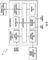
- FIG. 2 depicts a block diagram of the example ring scanning device 10, according to an embodiment of the present invention.
- the scanning device 10 is energized with electrical power supplied by a supercapacitor 21.
- the supercapacitor 21 is installed on board the scanning device 10 as a local component thereof.
- the ring scanner 10 may be recharged.
- An example embodiment may be implemented in which the supercapacitor 21 may be recharged, or replaced with a freshly charged replacement supercapacitor.
- the ring scanner 10, and/or the superconductor 21 may be docked (e.g., connected electrically and mechanically) to an electrical power supply disposed on an associated base station and operable for charging the docked supercapacitor.
- a pair (or more) of identically operable ring scanners may thus be used interchangeably, with one of them docked to a recharging source while the other energized the scanner 10.
- the supercapacitor 21 may be recharged fully and quickly.
- An example embodiment may be implemented in which the supercapacitor 21 may be recharged from a discharge state to a full charge and power supply availability state with a charging current of five Amperes (5A) in approximately three (3).
- the fully charged supercapacitor may provide electrical power at an average rate of 50 Milliamps (mA) to energize the ring scanner 10 for five (5) minutes.
- the supercapacitor 21 comprises a comprises a high-capacity electrochemical capacitive electrical device with capacitance values that can exceed 1,000 Faraday units (at a voltage of approximately 1.2 Volts) and has an energy storage capacity, per unit mass or volume, between one and two orders of magnitude greater than conventional capacitors.
- the supercapacitor 21 may be charged at a rate significantly higher than conventional rechargeable batteries, deliver electrical power to loads at similar high rates, and has high tolerance to repetitive and deep charge and discharge cycles, which is also superior to conventional rechargeable batteries.
- the supercapacitor 21 may comprise an electrostatic double-layer capacitance element, carbon based electrodes, an electrolyte, and Helmholtz double layer at an interface of the electrolyte and the electrode.
- the supercapacitor 21 may also (or alternatively) comprise an element characterized by electrochemical pseudocapacitance, and electrodes comprising metal oxide and/or conductive polymer materials, and operable using oxidation/reduction (redox) reactivity, Faradaic electron transfer, or other electrochemical processes.
- the supercapacitor may comprise a lithium ion hybrid capacitor.
- the supercapacitor 21 may sometimes also be referred to as an "ultracapacitor” and/or “electric double-layer capacitor” (EDLC).
- EDLC electric double-layer capacitor
- the supercapacitor 21 may be characterized and/or configured as described in Namisnyk, Adam M., A Survey of Electrochemical Supercapacitor Technology, U. Tech., Sydney, AU (2003 ), which is incorporated by reference in its entirety for all purposes as if fully set forth herein.
- the scanning device 10 comprises a scanning component 11, a local scanner bus 25, and an electrical charging port 29, and a scanner transceiver 22.
- the local scanner bus 25 is operable for conducting DC electrical power from the supercapacitor 11 to the scanning component 11, and the scanner transceiver 22.
- the local scanner bus 25 is also operable for conducting DC electrical power for charging (e.g., recharging or providing an initial charge to) the supercapacitor 11.
- the electrical power for charging the supercapacitor 11 may be provided thereto, via the electrical charging port 29, from an external electrical power supply (e.g., battery 41; FIG.4 ), such as in a base station with which the supercapacitor 21 (and the scanning device 10) may be docked.
- an external electrical power supply e.g., battery 41; FIG.4
- the ring scanning device 10 is operable for scanning the information source 19.
- the scanning component 11 is worn, during use, upon an extremity of a user.
- the scanning device 10 is operable for scanning the information source 19, accessing the information from the information source 19 based on the scanning, and generating a signal comprising data related to the accessed information.
- the supercapacitor 21 is operable as a power source for energizing the scanning component 11 during the scan operation.
- the scanning device 10 may be further operable for providing the generated scan signal to a base station (e.g., 31; FIG.3 , FIG.4 ).
- the base station is operable for processing the provided signal and worn by the user in a position remote from the scanning component.
- the transceiver 22 of the scanning device 10 comprises a first transceiver.
- the base station comprises a second transceiver, which is operable for exchanging data signals with the first transceiver 22.
- the data signals (e.g., "scan readouts") relate to the generated signal, which comprises the data related to the information accessed in the scan operation from the scan target 19.
- the scan related data signals may be exchanged between the transceiver 22 and the base station transceiver over RF.
- An example embodiment may be implemented in which the transceiver 22 sends the scan related RF data signals to the base station over the Industrial Scientific and Medical (ISM) band at or near 2.4 Gigahertz (GHz), referred to as Bluetooth®.
- ISM Industrial Scientific and Medical
- Bluetooth® 2.4 Gigahertz
- the local scanner bus 25 is also operable for communicatively coupling the scanner transceiver 22 and the scanning component 11 for receiving the generated scan signals therefrom.
- Scan related commands e.g., 'trigger scan'
- Scan related commands may be sent via the local scanner bus 25 to the scanning component 11.
- the scanning component 11 may be operable over optical wavelengths.
- the optical wavelengths may correspond to one or more infrared (IR), visible, and/or ultraviolet (UV) bands.
- FIG. 5A depicts an example optically operable version of the scanner 11, according to an embodiment of the present invention.
- the optically operable scanning component 11 comprises a light source 51 and a light sensor 52, each of which is energized by the supercapacitor power source 21.
- the light source 51 may comprise an active opto-electronic device, such as a laser diode (LD), a light emitting diode (LED), or an array of such devices.
- the light source 51 is operable for illuminating the scan target 19 with illuminating light
- illumination 53 Upon emission by the light source 51, the illumination 53 may be directed over the scan target 19 by illumination optics 56.
- the light sensor 52 is operable for detecting a reflection 54 of the illuminating light 53 from the scan target 19.
- the accessing of the information from the information source comprises the detection of the illuminating light reflected from the scan target.
- the light sensor 52 may comprise an active opto-electronic device such as a photodiode (PD), a charge coupled device (CCD), complementary metal oxide semiconductor (CMOS), charge-injection device (CID), charge modulation device (CMD), P-channel and/or N-channel metal oxide semiconductor field effect transistor (MOSFET) device, or an array of the devices.
- the devices of the array may comprise a plurality ("two or more") of the CCD, CMOS, PD, CID, CMD, P-channel MOSFET (PMOS), or N-channel MOSFET (NMOS) devices, and/or a video graphics array (VGA).
- the reflection 54 may be gathered and directed to, filtered, and/or focused on the light sensor 52 by detection optics 57.
- the illumination optics 56 and/or the detection optics 57 may comprise a system of one or more lenses, optical fibers, filters, and/or other passive optical devices such as prisms, mirrors, windows, diffraction and/or diffusion elements, etc.
- the scanning component 11 may be operable over one or more RF bands.
- FIG. 5B depicts an example RF operable version of the scanner 11, according to an embodiment of the present invention.
- the RF operable scanning component 11 comprises an RF transceiver 550, which is energized by the supercapacitor power source 21.
- the RF transceiver 550 comprises an RF transmitter ('Tx') element 551 and an RF receiver ('Rx') element 552.
- the RF Tx element 551 is operable for transmitting an RF signal 553, via a Tx antenna 556, over the scan target 19.
- the scan target 19 comprises an RFID tag 555, which may be sensitive to the RF transmission 553.
- the RFID tag 555 may receive the RF Tx 553 via an internal antenna of its own.
- An internal IC component of the RFID tag 550 is energized by the received RF transmission signal 553 and responsive thereto, may emit a RFID return signal 554, which is transmitted via its internal antenna.
- the RF Rx element 552 receives the RFID return signal 554 over the Rx antenna 557.
- the RFID return signal 554 comprises a data signal corresponding to the information of the scan target 19.
- the RF transceiver 550 (or a component associated therewith) is operable for generating the scan related data signal.
- the scan target 19 comprises the information source, which may comprise the RFID tag 550 or a graphic medium, comprising graphic information.
- the graphic information may comprise indicia, symbols, geometric, one dimensional (1D), and/or two dimensional (2D) data patterns, bar codes, matrix code data patterns, and/or text, which e.g., may be alphanumeric, character, and/or syllabary based.
- FIG. 6A depicts an example image based scan target 61, according to an embodiment of the present invention.
- the image based scan target 61 comprises graphic information 610.
- the information 610 comprises an image 612 disposed over a graphic medium 611.
- FIG. 6B depicts an example 1D data pattern scan target 62, according to an embodiment of the present invention.
- the 1D bar code symbol 622 comprises an example bar code pattern 622 disposed over a graphic medium 622.
- the bar code symbol 622 comprises a plurality of bar elements 66a and a plurality of space elements 68b.
- the space elements 68b are disposed in parallel with the bar elements 66a.
- the bar code symbol 620 may correspond to data patterns related to, for example, an International (or "European”) Article Number and/or Universal Product Code (EAN/UPC symbology) pattern, PDF417 (ISO/EC-15438 related) pattern, which comprise four of the vertical bar like symbols 66a disposed over 17 of the horizontally disposed spacer symbols 68b), 1D dot code pattern, or other 1D symbols.
- EAN/UPC symbology International (or "European") Article Number and/or Universal Product Code
- PDF417 ISO/EC-15438 related
- FIG. 6C depicts an example 2D data pattern scan target 63, according to an embodiment of the present invention.
- the 2D scan target 63 comprises a matrix pattern, which comprises an array of 2D graphic symbol parts, such as squares and other rectangle and polygons, disposed over a graphic medium 655.
- the matrix data pattern 650 may correspond to a 2D data pattern related to, for example, quick-response (QR) and/or Han Xin graphical or geometric data matrices, or other 2D symbols.
- QR quick-response
- Han Xin graphical or geometric data matrices or other 2D symbols.
- FIG. 6D depicts an example text based code pattern scan target 64, according to an embodiment of the present invention.
- the text based scan target 64 comprises alphanumeric, character, or syllabary based text or other text related graphic symbol parts (e.g., OCR patterns), disposed over a graphic medium 644.
- the code pattern 640 may comprise human readable and optical character recognition (OCR) readable symbol parts, such as numbers, letters, characters, and syllables printed on a print medium 644.
- the data pattern 640 may comprise a 2D data pattern related to, for example, OCR-B or OCR-A, or other 2D symbols.
- FIG. 3 depicts an example mobile scanning system 30, according to an embodiment of the present invention.
- the mobile scanning system 30 comprises the ring scanning component 10, a base station 31, and an electrical power supply (e.g., battery 41; FIG.4 ).
- an electrical power supply e.g., battery 41; FIG.4 .
- the ring scanning component 10 is worn, during scan operations performed over scan targets, upon an extremity, such as one or more fingers, the palm, or the back of the hand of a user.
- the scanning component 10 is energized directly by an installed, on-board supercapacitor power source (21; FIG.2 ).
- the scanning component 10 is operable for accessing the information from the information source based on the scan operation, and generating a signal comprising data related to the accessed information.
- the base station 31 is worn by the user in a position remote from the scanning component, and operable for processing the provided signal.
- the position at which the base station is worn may comprise an article of clothing 39 or an accessory item worn by the user.
- the accessory item may comprise a belt 38 or a strap 37.
- the clothing article 39 or the accessory item (38, 37) supports or suspends the base station 31 physically, e.g., mechanically, upon the user in a safe, comfortable, and ergonomically efficient location in relation to the user's body, which is remote from the ring scanning component 10.
- the clothing article 39 or the accessory item (38, 37) may comprise a belt, vest, strap, pocket disposed in the clothing article, or a holster or pouch that may be suspended from the belt and/or the strap.
- the ring scanner 10 and the base station 31 are communicatively coupled wirelessly via an exchange of RF signals.
- An example embodiment may be implemented in which the ring scanner 10 and the base station 31 communicate via Bluetooth® RF signals (or other ISM RF band).
- FIG. 4 depicts an example base station 31, according to an embodiment of the present invention.
- the base station electrical power supply 41 is disposed locally in relation to the base station.
- the base station electrical power supply 41 comprises a rechargeable battery 414.
- the battery 414 may comprise a lithium ion (Li-ion) battery.
- the base station electrical power supply 41 is operable for providing DC electrical power for charging the supercapacitor power source 21 of the scanning component 10, and for energizing the base station 31.
- the base station electrical power supply 41 may comprise the battery 414, a port 48 for charging (e.g., recharging) the battery 414, and a port 49 for charging the supercapacitor power source 21 of the ring scanning component 10.
- the scanning component 10 may comprise a first of a plurality of substantially identical and operationally interchangeable scanning components.
- the mobile scanning system 30 may comprise at least a second of the scanning components 43. During the operation of the first scanning component 10, the at least second scanning component 43 may be, optionally, recharged via the port 49.
- the supercapacitor power supply 21 may comprises a first of a plurality of substantially identical and operationally interchangeable supercapacitor power supplies.
- the mobile scanning system 30 comprises at least a second of the supercapacitor power supplies.
- the at least second s supercapacitor power supply may be, optionally, recharged via the port 49.
- the base station 31 comprises a base station bus 45, and the base station ("second") RF transceiver 44.
- the base station transceiver 44 is operable for receiving the scan related data signals generated by the ring scanner 10 and transmitted by the scanner ("first") transceiver 22 ( FIG.2 ), e.g., via Bluetooth®.
- the base station transceiver 44 may also be operable for sending scan related commands (e.g., 'configuration') to the ring scanner 10.
- the base station 31 may also comprise a scan processor 42 and a processed scan report transceiver 46.
- the scan processor 42 is operable for processing the information received in the scan related data signals and providing a corresponding output processed scan data signal.
- the processed scan report transceiver 46 is operable for transmitting the processed scan data signal to an external scan data processing computer entity 47. Additionally or alternatively, the processed scan data signal may be processed locally in relation to the base station 31.
- the base station 31 may comprise an on board computer 701, which may be disposed in the base station 31 or deployed and operated locally therewith.
- the base station bus 45 may be operable for distributing electrical power from the battery 414 to the other components of the base station 31.
- the base station bus 45 may be operable for allowing the other components of the base station 31 to exchange data signals.
- the mobile scanner system 30 may be operable for performing a scanner process, which may relate to an example scanning method described below.
- An example embodiment of the present invention relates to a method 30 for scanning a target source of information.
- the method 80 may be performed by the scanner system 30, described above.
- a scanner is energized by electrical power supplied by a charged supercapacitor.
- the scanner is worn, during a scan operation performed over the target information source, upon an extremity of a user.
- a step 82 the information is accessed from the scan target information source based on the scan operation.
- a signal is generated, which comprises data related to the accessed information.
- the generated data signal is processed in relation to reading the accessed information.
- the supercapacitor device comprises a first of a plurality of supercapacitor devices.
- the method 80 may further comprise charging at least a second of the supercapacitor devices.
- the first of the supercapacitor devices may be replaced with the at least second of the supercapacitor devices.
- the step of energizing the scanner is performed by the at least second of the supercapacitor devices.
- An example embodiment of the present invention relates to a non-transitory computer readable storage medium comprising instructions. Upon execution by one or more processors of a computer system, the instructions are operable for performing, controlling, and/or programming one or more steps of the scanning method 80.
- An example embodiment may be implemented in which one or more components of the scanner system 100 (e.g., scan processor 42) are configured in electronic or computer based hardware, software stored physically (e.g., electronically, optically, electromagnetically) in non-transitory computer readable storage media such as dynamic memory, flash memory, drives, caches, buffers, registers, latches, memory cells, or the like.
- software stored physically (e.g., electronically, optically, electromagnetically) in non-transitory computer readable storage media such as dynamic memory, flash memory, drives, caches, buffers, registers, latches, memory cells, or the like.
- FIG. 7 depicts an example computer and network platform 700, with which an embodiment of the present invention may be practiced.
- the computer and network platform 700 comprises a first computer system ("computer") 701 and a data communication network 788.
- the computer 701 comprises one or more components 775 of the scanner system 30 (e.g., scan processor 42).
- An example embodiment may be implemented in which the computer 701 comprises a component of the base station 31, or is disposed locally in relation thereto and/or deployed and operated locally in association therewith.
- the computer 701 also comprises a touchscreen display 725.
- a graphical user interface (GUI) 780 is rendered and actuated by the touchscreen display 725.
- the computer 701 may also comprise a camera 766.
- An example embodiment may be implemented in which the camera 766 functions with the scanner system 30.
- the network 788 may comprise a packet-switched data network operable based on transfer control and internetworking protocols (e.g., TCP/IP).
- the computer 701 may be coupled communicatively, and exchange data signals, over the data communication network 788 with at least a second computer 798, which is coupled communicatively with the data network 788.
- the data network 788 may comprise a portion of one or more other networks and/or two or more sub-network (“subnet") components.
- the data network 788 may comprise a portion of the internet and/or a particular wide area network (WAN).
- the network 788 may also comprise one or more WAN and/or local area network (LAN) subnet components. Portions of the data network 788 may be operable wirelessly and/or with wireline related means.
- the data network 788 may also comprise, at least in part, a communication network such as a digital telephone network.
- An example embodiment may be implemented in which the computer 701 is operable for sending data to the computer 798 in relation to the operations of the scanner system 30 over the data network 788.
- the computer 798 may then store scanner system operation related data in the database 777, from which it may be retrieved at a later time.
- the computer 701 may be operable for presenting a query to the computer 798 for input to the database 777, and for receiving corresponding replies, over the data communications network 788.
- the computer 701 comprises a plurality of electronic components, each of which is coupled to a data bus 702.
- the data bus 702 is operable for allowing each of the multiple, various electronic components of computer 701 to exchange data signals with each of the other electronic components.
- the electronic components of the computer 701 may comprise IC devices, including one or more microprocessors.
- the electronic components of the computer 701 may also comprise other IC devices, such as a microcontroller, field-programmable gate array (FPGA) or other programmable logic device (PLD) or application-specific IC (ASIC).
- FPGA field-programmable gate array
- PLD programmable logic device
- ASIC application-specific IC
- the microprocessors may comprise a central processing unit (CPU) 704.
- the CPU 704 is operable for performing general data processing functions related to operations of the GRUI and other components of the computer 701.
- the electronic components of the computer 701 may also comprise one or more other processors 744.
- the other microprocessors may comprise a graphics processing unit (GPU) and/or digital signal processor (DSP) 704, which are each operable for performing data processing functions that may be somewhat more specialized than the general processing functions, as well as sometimes sharing some processing functions with the CPU 704.
- GPU graphics processing unit
- DSP digital signal processor
- One of the processors 744 may also be operable as a "math” (mathematics) coprocessor.
- the math co-processor, DSP and/or GPU (“DSP/GPU") 744 are operable for performing computationally intense data processing.
- the computationally intense processing may relate to imaging, image evaluation, graphics, dimension measurements, wireframe manipulations, coordinate system management, control, and other (e.g., mathematical, financial) information, any of which may relate to the scan based information.
- One of the microprocessors may comprise an image processor 733, which is operable for processing images and video feed from the camera 766 and scan related image data from a scan target of the scanner system 30.
- the data processing operations comprise computations performed electronically by the image processor 333, CPU 704, and the DSP/GPU 744.
- the microprocessors may comprise components operable as an ALU, a FPU, and associated memory cells.
- the memory cells comprise non-transitory data storage media, which may be configured as caches (e.g., "L1,” "L2"), registers, latches and/or buffers.
- the memory cells are operable for storing data electronically in relation to various functions of the processor.
- a translational look-aside buffer may be operable for optimizing efficiency of use of content-addressable memory (CAM) by the CPU 704, and/or the DSP/GPU 744, etc.
- the computer 701 also comprises non-transitory computer readable storage media operable for storing data, e.g., electronically.
- the computer readable storage media comprises a main memory 706, such as a random access memory (RAM) or other dynamic storage medium.
- the main memory 706 is coupled to data bus 702 for storing information and instructions, which are to be executed by the CPU 704.
- the main memory 706 may also be used for storing temporary variables or other intermediate information during execution of instructions by the CPU 704.
- Other memories represented in the present description with reference to the RAM 706) may be installed for similar uses by the DSP/GPU 744.
- the printing evaluation system 300 further comprises a read-only memory (ROM) 708 or other static storage medium coupled to the data bus 702.
- the ROM 708 is operable for storing static information and instructions for use by the CPU 704.
- the non-transitory storage media may comprise at least one data storage device 710.
- the data storage device 710 is operable for storing information and instructions and allowing access thereto.
- the data storage device 710 may comprise a magnetic disk drive, flash drive, or optical disk drive (or other non-transitory computer readable storage medium).
- the data storage device 710 comprises non-transitory media coupled to data bus 702, and may be operable for providing a "virtual memory" function.
- the virtual memory operations of the storage device 710 may supplement, at least temporarily, storage capacity of other non-transitory media, such as the RAM 706.
- An example embodiment may be implemented in which one or more of the processors and/or the non-transitory storage components perform computations relating to operations of one or more components of the base station 30.
- the non-transitory storage media comprises instructions 783, which are stored (e.g., electronically, magnetically, optically, physically, etc.) in relation to software for programming, controlling, and/or configuring operations of the computer 701 and its components, including the printing system 100, the camera 766, the GUI 80, etc.
- the instructions 783 may also relate to the performance of one or more steps of the scanning method 80 ( FIG.8 ).
- Instructions, programming, software, settings, values, and configurations, etc. related to the method 60, the scanning system 30 and its components 775, and other operations of the computer 701 are stored (e.g., magnetically, electronically, optically, physically, etc.) by the storage medium 710, memory, etc.
- the computer 701 comprises a user-interactive display configured as the touchscreen 725, which is operable as a combined display and the GUI 780.
- the touchscreen 725 may comprise a liquid crystal display (LCD), which is operable for rendering images by modulating variable polarization states of an array of liquid crystal transistor components.
- the touchscreen 725 also comprises an interface operable for receiving haptic inputs from a user.
- the haptic interface of the GUI 780 and touchscreen 725 may comprise, e.g., at least two arrays of microscopic (or transparent) conductors, each of which is insulated electrically from the other and disposed beneath a surface of the display 725 in a perpendicular orientation relative to the other.
- the haptic inputs comprise pressure applied to the surface of the touchscreen 725 and GUI 780, which cause corresponding local changes in electrical capacitance values proximate to the pressure application that are sensed by the conductor grids to effectuate a signal corresponding to the input.
- Images and video received from the camera 766 and/or the scanner system 30 may also be presented on the display 725.
- the touchscreen 725 may be implemented operably for rendering images over a heightened (e.g., high) dynamic range (HDR).
- the rendering of the images may also be based on modulating a back-light unit (BLU).
- the BLU may comprise an array of light emitting diodes (LEDs).
- the LCDs may be modulated according to a first signal and the LEDs of the BLU may be modulated according to a second signal.
- the touchscreen 725 may render an HDR image by coordinating the second modulation signal in real time, relative to the first modulation signal.
- the display 725 may comprise an organic LED (OLED) array.
- OLED organic LED
- the display 725 may also (or alternatively) comprise a display operable over a standard dynamic range (SDR), sometimes also referred to as a "low dynamic range” (LDR).
- SDR standard dynamic range
- LDR low dynamic range
- An input receiver 714 may comprise one or more electromechanical switches, which may be implemented as buttons, escutcheons, microelectromechanical sensors (MEMS) or other sensors, dual in-line package (DIP) switch, etc.
- the input receiver 714 may also comprise cursor and trigger controls such as a mouse, joystick, etc. and/or a keyboard.
- the keyboard may comprise an array of alphanumeric and/or ideographic, syllabary based keys operable for typing corresponding letters, number, and/or other symbols.
- the keyboard may also comprise an array of directional (e.g., "up/down,” "left/right") keys, operable for communicating commands and data selections to the CPU 704 and for controlling movement of a cursor rendering over the touchscreen display 725.
- the inputs may also be made by voice actuation.
- the directional keys may be operable for presenting two (2) degrees of freedom of a cursor, over at least two (2) perpendicularly disposed axes presented on the display component of the touchscreen 725.
- a first 'x' axis is disposed horizontally.
- a second 'y' axis, complimentary to the first axis, is disposed vertically.
- the printing evaluation system 300 is thus operable for specifying positions over a representation of a geometric plane and/or other coordinate systems.
- Execution of instruction sequences contained in the storage media 710 and main memory 706 cause the CPU 704 to perform processing related to general operations of the computer 701, the DSP/GPU 744 to perform various other processing operations, and the components of the printing system 100 to perform processing steps related to the example method 80. Additionally or alternatively, hard-wired circuitry may be used in place of, or in combination with the software instructions. Thus, the computer 701 is not limited to any specific combination of circuitry, hardware, firmware, or software.
- Non-volatile media comprises, for example, configured/programmed active elements of the scan processor 42
- Volatile media comprises dynamic memory associated, e.g., with the RAM 706.
- Transmission media comprises coaxial cables, copper wire and other electrical conductors and fiber optics, including the wires (and/or other conductors or optics) that comprises the data bus 702.
- Transmission media can also take the form of electromagnetic radiation (e.g., light waves), such as may be generated at RF, and IR and other optical frequencies.
- Data communications may also be effectuated using other means, including acoustic (e.g., sound related) or other mechanical, vibrational, or phonon related media.
- Non-transitory computer-readable storage media may comprise, for example, flash drives such as may be accessible via universal serial bus (USB) or any medium from which the computer 701 can access, read, receive, and retrieve data.
- USB universal serial bus
- Non-transitory computer readable storage media may be involved in carrying one or more sequences of one or more instructions to CPU 704 for execution.
- the instructions may initially be carried on a magnetic or other disk of a remote computer (e.g., computer 798).
- the remote computer can load the instructions into its dynamic memory and send the instructions over networks 788.
- the scanning system 30 can receive the data over the network 788 and use an IR, RF, or other transmitter means to convert the data to corresponding signals.
- An IR, RF or other signal detector or receiver (“receiver") coupled to the data bus 702 can receive the data carried in the corresponding signals and place the data on data bus 702.
- the operations associated with the transmitter and the receiver may be combined in a transceiver.
- the transmitter, receiver, and/or transceiver may be associated with the interfaces 718.
- the data bus 702 carries the data to main memory 706, from which CPU 704 and the DSP/GPU 744 retrieve and execute the instructions.
- the instructions received by main memory 706 may optionally be stored on storage device 710 either before or after execution by CPU 704.
- the interfaces 718 may comprise a communication interface coupled to the data bus 702.
- the communication interface is operable for providing a two-way (or more) data communication coupling to a network link 720, which may connect wirelessly over RF to the network 788.
- Wireless communication may also be implemented optically, e.g., at IR frequencies.
- Signals may be exchanged via the interfaces 718 with an external device 799 (e.g., another computer or external storage device) through a compatible communication port 719.
- the input receiver 417 may provide signals to the components 775 of the scanner system 30, and other components of the computer 701 via the port 719.
- the communication interface 718 sends and receives electrical, electromagnetic or optical signals that carry digital data streams representing various types of information.
- the network link 720 provides data communication through the network 788 to other data devices.
- the input receiver 417 may provide signals to the printer system 100 and other components of the computer 701 via the network links 720 and/or the data communications network 788.
- the network 788 may use one or more of electrical, electromagnetic, and/or optical signals carrying digital data streams.
- the signals sent over the network 788 and through the network link 720 and communication interface 718 carry the digital data to and from the scanning system 30.
- the scanning system 30 can send messages and receive data, including program code, through the network 788, network link 720, and communication interface 718.
- Example embodiments of the present invention are thus described in relation to a scanning device, mobile scanner system, and method for scanning a source of information.
- the scanning device is energized by an on-board supercapacitor and is worn upon an extremity of a user.
- the scanning device is operable for scanning the information source, accessing the information from the source based on the scanning, and generating a signal comprising data related to the accessed information.
- the generated scan data signal is transmitted for processing to a base station, which is worn remotely from the scanning device, for example on the user's belt.
- Embodiments of the present invention thus provide a mobile scanner system with a ring scanning component configured for wear upon the fingers of an operator's hand and independent of a power cable extended for providing its electrical energy.
- An example embodiment may be implemented in which the base station of the mobile scanner system is positioned, mounted, supported, and worn on a part of an operator's body, clothing, or accessories that are accessible, balanced, comfortable, convenient, efficient ergonomically, non-fatigue causing, safe, and secure.
- the ring scanner is energized independent of direct physical connection with the base electrical power source battery, and without adding the weight and size of a dedicated on-board battery thereto.
Landscapes
- Engineering & Computer Science (AREA)
- Physics & Mathematics (AREA)
- Health & Medical Sciences (AREA)
- Toxicology (AREA)
- Theoretical Computer Science (AREA)
- Electromagnetism (AREA)
- General Physics & Mathematics (AREA)
- Computer Vision & Pattern Recognition (AREA)
- Artificial Intelligence (AREA)
- General Health & Medical Sciences (AREA)
- Computer Networks & Wireless Communication (AREA)
- Computer Hardware Design (AREA)
- Signal Processing (AREA)
- Computer Security & Cryptography (AREA)
- Human Computer Interaction (AREA)
- General Engineering & Computer Science (AREA)
- Image Input (AREA)
Abstract
Description
- The present invention relates generally to scanners. More particularly, example embodiments of the present invention relate to scanners configured for wear on an appendage of users.
- Generally speaking, scanners are operable for accessing, capturing, gathering, reading, and/or sensing data encoded, presented, or stored by an information source. For example, optical scanners may be operable for reading graphic data patterns and others. The optical scanners may be configured to read one dimensional (1D) data patterns such as bar codes and/or two dimensional (2D) data patterns such as matrix codes. Data encoded by radio frequency identification (RFID) tags may be read by compatible scanners sensitive to the radio frequency (RF) to which the tag responds.
- Scanners may be used in a wide variety of applications endeavors, and enterprises. For example, scanners are used in various logistic and commercial applications. The bar codes, matrix patterns, and RFID tags identify and characterize items such as inventory, parts, products, purchases, returns, stock, and supplies. The scanners may be deployed, disposed, and/or used in configurations suited for particular applications. For example, scanners used in high throughput logistic and/or commercial data gathering applications may be configured for ease and simplicity of use by an operator.
- To maximize user mobility and productivity, such scanners may be designed for light weight, small form factor, ergonomic efficiency and safety, high portability and mobility, and power availability and longevity. Some contemporary mobile scanners may be worn on parts of the operator's body. "Ring scanners," for example, comprise a scanning device worn on a finger of the operator's hand "like a ring."
- The scanners illuminate a scan target such as a 1D or 2D graphic data pattern with optical or RF radiation, sense a return of a portion of (or radiation emitted responsive to) the illuminating radiation therefrom, and generate a corresponding detection signal. Processing performed on the detection signal allows the data encoded by the scan target to be read. The processing may be performed on a base module, which is typically worn on the wrist (or another part of the forearm) of the operator. Power for energizing the ring scanner may be provided by a battery power source, which is typically disposed with or deployed on the wrist mounted base module.
- For example, the '8650'™ Ring Scanner (commercially available by Honeywell™ International, a corporation in New Jersey) comprises a productivity tool for use by mobile operators for scanning barcodes. The 8650 ring scanner comprises a ring based scanning device worn on the fingers of an operator, and a base module worn on the wrist of the operator. The ring scanning device is communicatively coupled to the base module by a RF signal. The base station processes the data read by the ring scanner, and may also comprises a radio transmitter or transmitter/receiver (transceiver) operable for transmitting the data read by the base station to a remote computer for processing therewith.
- The ring scanners themselves are lightweight and readily mobile. However, the base, which contains the battery power supply, one or more radio components, and a mobile computer, may be significantly heavier and larger than the ring scanner. Further, cables are used for feeding direct current (DC) electrical power from the battery in the wrist mounted base station to energize the ring scanner.
- The weight and size of the wrist mounted battery and base station may cause muscular fatigue, strain, and/or overuse to the operators during extended scanning operations, which may reduce productivity. Over time, user actions taken responsive to the strain, etc. may present issues relevant to repetitive motion and associated heath issues. Moreover, the power cables extended between the wrist-mounted base station and the ring scanner may be snagged during use.
- Such snagging can be inconvenient around protrusions, which are not uncommon in logistical and industrial settings. In such settings however, the snagging may also present a safety issue. For example, around moving equipment such as conveyors or other machinery, the snagged power cable may become entangled. Attached to the wrist of the operator, the possibility of such entanglement presented by the snagged power cable may merit an exercise of caution.
- While maintaining the convenience of the ring scanning component of a mobile scanner system configured for wear upon the fingers of an operator's hand, it could be useful to obviate the extension of a cable for energizing the scanning component. In so doing, it could also be useful to for the base station, which may include a base electrical power source battery, to be positioned, mounted, supported, and/or worn on a strong and/or indefatigable part of an operator's body, where they are accessible, balanced, comfortable, convenient, efficient ergonomically, non-fatigue causing, safe, and secure, e.g., in relation to the wrist. It could be further useful to energize the ring scanning component, apart from a direct physical connection with the base electrical power source battery, and/or without adding the weight and size of a dedicated on-board battery thereto.
- Accordingly, in one aspect, an example embodiment of the present invention relates to a mobile scanner system with a ring scanning component configured for wear upon the fingers of an operator's hand and independent of a power cable extended for providing its electrical energy. An example embodiment may be implemented in which the base station of the mobile scanner system is positioned, mounted, supported, and worn on a part of an operator's clothing, or accessories where it is accessible, balanced, comfortable, convenient, efficient ergonomically, non-fatigue causing, safe, and secure. In an example embodiment, the ring scanner is energized independent of direct physical connection with the base electrical power source battery, and without adding the weight and size of a dedicated on-board battery thereto.
- An example embodiment of the present invention relates to a device for scanning a source of information. The scanning device comprises a scanning component worn upon an extremity of a user. The scanning device is operable for scanning the information source, accessing the information from the source based on the scanning, and generating a signal comprising data related to the accessed information. A supercapacitor is operable as a power source for energizing the scanning component directly and is installed locally in relation thereto.
- An example embodiment of the present invention relates to a mobile system for scanning a source of information. The mobile scanning system comprises a scanning component energized by a supercapacitor, a base station, and an electrical power supply.
- The scanning component may correspond to the scanning device summarized above, and may be further operable for providing the generated signal to a base station. The base station is operable for processing the provided signal. The electrical power supply is operable for charging the supercapacitor power source of the scanning component, and for energizing the base station.
- The scanning component comprises a first transceiver, and the base station comprises a second transceiver, which is operable for exchanging data signals with the first transceiver. The data signals relate to the generated signal comprising the data related to the accessed information.
- The base station is worn by the user in a position remote from the scanning component, such as on a belt.
- The information source may comprise a graphic medium. The information source may also, or alternatively, comprise a RFID tag. The scanning component may be operable optically and/or by RF.
- The electrical power supply of the base station may comprise a battery and a port for docking and charging the supercapacitor power source of the scanning component. The scanning component may comprise a first of a plurality of substantially identical and operationally interchangeable scanning components. The mobile scanning system may comprise at least a second of the scanning components. During the operation of the first scanning component, the at least second scanning component may be, optionally, recharged.
- Alternatively or additionally, the supercapacitor power supply may comprises a first of a plurality of substantially identical and operationally interchangeable supercapacitor power supplies, wherein the mobile scanning system comprises at least a second of the supercapacitor power supplies. During the operation of the first supercapacitor power supply, the at least second supercapacitor power supply may be, optionally, recharged.
- An example embodiment of the present invention relates to a method for scanning a target source of information. The method may be performed by the mobile computer system summarized above.
- In another aspect, the present invention embraces a device that includes a scanner designed to be worn upon an extremity of a user and operable to scan a target having machine-readable information to obtain the machine-readable information and includes a supercapacitor power source to provide power to the scanner.
- In yet another aspect, the present invention embraces a system that includes a scanner, a base station, and an electrical power supply. Typically, the scanner is designed to be worn upon an extremity of a user and operable to scan a target having machine-readable information to obtain the machine-readable information and includes a supercapacitor power source to provide power to the scanner. The base station is typically designed to be worn by the user in a position remote from the scanner. The electrical power supply is typically disposed locally in relation to the base station to provide power to the base station. Typically, the scanner outputs the machine-readable information to the base station to decode and the power supply charges the supercapacitor power source when the scanner is docked to the base station.
- In yet another aspect, the present invention embraces a method that includes energizing, with a supercapacitor device, a scanner worn, during a scan operation performed over a target having machine-readable information, upon an extremity of a user, obtaining the machine-readable information based on the scan operation performed over the target, and generating a signal including data related to the obtained information, wherein the generated data signal is processed in relation to reading the obtained information.
- The foregoing illustrative summary, as well as other example features, functions and/or aspects of embodiments of the invention, and the manner in which the same are accomplished, are further explained within the following detailed description of example embodiments and each figure ("FIG.") of the accompanying drawings.
-
-
FIG. 1A depicts an example ring scanning device from a first perspective, according to an embodiment of the present invention; -
FIG. 1B depicts the example ring scanning device from a second perspective, according to an embodiment of the present invention; -
FIG. 2 depicts a block diagram of an example ring scanning device, according to an embodiment of the present invention; -
FIG. 3 depicts an example mobile scanning system, according to an embodiment of the present invention; -
FIG. 4 depicts an example base station, according to an embodiment of the present invention; -
FIG. 5A depicts an example optically operable scanner, according to an embodiment of the present invention; -
FIG. 5B depicts an example RF operable scanner, according to an embodiment of the present invention; -
FIG. 6A depicts an example image related scan target, according to an embodiment of the present invention; -
FIG. 6B depicts an example 1D data pattern scan target, according to an embodiment of the present invention; -
FIG. 6C depicts an example 2D data pattern scan target, according to an embodiment of the present invention; -
FIG. 6D depicts an example text based 'OCR' scan target, according to an embodiment of the present invention; -
FIG. 7 depicts an example computer and data network, with which an embodiment of the present invention may be practiced; and -
FIG. 8 depicts a flowchart for an example scanning method, according to an embodiment of the present invention. - Example embodiments of the present invention are described in relation to device, mobile system, and method for scanning a source of information. During scan operations, the scanning device (e.g., a scanner) is energized by an on-board supercapacitor and is worn upon an extremity of a user. The scanning device is operable for scanning the information source (e.g. a target having machine-readable information), accessing the information (e.g., machine-readable information) from the source based on the scanning, and generating a signal comprising data related to the accessed information. The generated scan data signal is transmitted for processing to a base station, which is worn remotely from the scanning device, for example on the user's belt.
- Embodiments of the present invention thus provide a mobile scanner system with a ring scanning component configured for wear upon the fingers of an operator's hand and independent of a power cable extended for providing its electrical energy. An example embodiment may be implemented in which the base station of the mobile scanner system is positioned, mounted, supported, and worn on a part of an operator's clothing or accessories that are accessible, balanced, comfortable, convenient, efficient ergonomically, non-fatigue causing, safe, and secure. In an example embodiment, the ring scanner is energized independent of direct physical connection with the base electrical power source battery, and without adding the weight and size of a dedicated on-board battery thereto.
- An example embodiment of the present invention relates to a device for scanning a source of information. The scanning device comprises a scanning component worn upon an extremity of a user. The scanning device is operable for scanning the information source, accessing the information from the source based on the scanning, and generating a signal comprising data related to the accessed information. A supercapacitor is operable as a power source for energizing the scanning component directly and is installed locally in relation thereto.
- The scanning component may be further operable for providing the generated signal to a base station. The base station is operable for processing the provided signal and worn by the user in a position remote from the scanning component. The scanning component comprises a first transceiver, and the base station comprises a second transceiver, which is operable for exchanging data signals with the first transceiver. The data signals relate to the generated signal comprising the data related to the accessed information.
- The scanning component may comprise a light source and a light sensor. The light source is operable for illuminating a scan target with illuminating light. The light sensor is operable for detecting a reflection of the illuminating light from the scan target. The accessing of the information from the information source comprises the detection of the illuminating light reflected from the scan target.
- The information source may comprise a graphic medium. The scanning of the information source, and/or the accessing of the information therefrom based on the scanning is performed optically. The information source may comprise indicia, symbols, geometric, 1D, and/or 2D data patterns, bar codes, matrix code data patterns, and/or text, which e.g., may be alphanumeric, character, and/or syllabary based.
- The information source may comprise an RFID tag. The scanning of the information source, and/or the accessing the information therefrom based on the scanning are performed at an RF operating characteristic of the RFID tag.
- An example embodiment of the present invention relates to a mobile system for scanning a source of information. The mobile scanning system comprises a scanning component, a base station, and an electrical power supply.
- The scanning component comprises a ring scanner worn, during a scan operation performed over a scan target, upon an extremity, such as one or more fingers, the palm, or the back of the hand of a user. The scanning component is energized directly by an installed, on-board supercapacitor power source. The scanning component is operable for accessing the information from the information source based on the scan operation, and generating a signal comprising data related to the accessed information.
- The base station worn by the user in a position remote from the scanning component operable for processing the provided signal. The electrical power supply is disposed locally in relation to the base station. The electrical power supply is operable for charging the supercapacitor power source of the scanning component, and for energizing the base station.
- The position at which the base station is worn may comprise an article of clothing or an accessory item worn by the user. The clothing article or the accessory item supports or suspends the base station physically, e.g., mechanically, upon the user in a safe, comfortable, and ergonomically efficient location in relation to the user's body, which is remote from the scanning component. For example, the clothing article or the accessory item may comprise a belt, vest, strap, pocket disposed in the clothing article, or a holster or pouch that may be suspended from the belt and/or the strap.
- The electrical power supply of the base station may comprise a battery and a port for charging the supercapacitor power source of the scanning component. The scanning component may comprise a first of a plurality of substantially identical and operationally interchangeable scanning components. The mobile scanning system may comprise at least a second of the scanning components. During the operation of the first scanning component, the at least second scanning component may be, optionally, recharged.
- Alternatively or additionally, the supercapacitor power supply may comprises a first of a plurality of substantially identical and operationally interchangeable supercapacitor power supplies, wherein the mobile scanning system comprises at least a second of the supercapacitor power supplies. During the operation of the first supercapacitor power supply, the at least second s supercapacitor power supply may be, optionally, recharged.
- An example embodiment of the present invention relates to a method for scanning a target source of information. The method comprises energizing a scanner by electrical power supplied by a charged supercapacitor. The scanner is worn, during a scan operation performed over the target information source, upon an extremity of a user. The information is accessed from the information source based on the scan operation. A signal is generated, which comprises data related to the accessed information. The generated data signal is processed in relation to reading the accessed information.
- An example embodiment may be implemented in which the supercapacitor device comprises a first of a plurality of supercapacitor devices. The method further comprises charging at least a second of the supercapacitor devices. The first of the supercapacitor devices may be replaced with the at least second of the supercapacitor devices. Upon the replacing of the first supercapacitor with the second supercapacitor, the step of energizing the scanner is performed by the at least second of the supercapacitor devices.
- An example embodiment of the present invention relates to a device for scanning a source of information. During use, the scanning device is worn upon an extremity of the user. For example, the scanning device may comprise a ring scanner worn on one or more digits, the palm, or the back of the user's hand.
-
FIG. 1A depicts an examplering scanning device 10 from a first perspective, according to an embodiment of the present invention. In the first perspective, thering scanner 10 is shown, as worn, with respect to an upper (or lower) substantially planar surface of the hand of a user. -
FIG. 1B depicts theexample ring scanner 10 from a second perspective, according to an embodiment of the present invention. In the second perspective, thering scanner 10 is shown, as worn, with respect to the thumb side edge of the hand of a user. - The
ring scanner 10 is energized directly by an on-board supercapacitor power source (e.g.,supercapacitor 21;FIG.2 ). Thering scanner 10 comprises ascanning component 11, which is operable for scanning (e.g., "reading," accessing information stored by) ascan target 19 information source. -
FIG. 2 depicts a block diagram of the examplering scanning device 10, according to an embodiment of the present invention. During use, while performing scanning operations, thescanning device 10 is energized with electrical power supplied by asupercapacitor 21. Thesupercapacitor 21 is installed on board thescanning device 10 as a local component thereof. - Upon completion of a run of scanning operations, or receipt of an indication related to the
supercapacitor 21 having assumed a discharged, or low power supply capacity state, thering scanner 10 may be recharged. An example embodiment may be implemented in which thesupercapacitor 21 may be recharged, or replaced with a freshly charged replacement supercapacitor. For example, thering scanner 10, and/or thesuperconductor 21 may be docked (e.g., connected electrically and mechanically) to an electrical power supply disposed on an associated base station and operable for charging the docked supercapacitor. A pair (or more) of identically operable ring scanners may thus be used interchangeably, with one of them docked to a recharging source while the other energized thescanner 10. - From a discharged state, the
supercapacitor 21 may be recharged fully and quickly. An example embodiment may be implemented in which thesupercapacitor 21 may be recharged from a discharge state to a full charge and power supply availability state with a charging current of five Amperes (5A) in approximately three (3). Upon the recharge, the fully charged supercapacitor may provide electrical power at an average rate of 50 Milliamps (mA) to energize thering scanner 10 for five (5) minutes. - The
supercapacitor 21 comprises a comprises a high-capacity electrochemical capacitive electrical device with capacitance values that can exceed 1,000 Faraday units (at a voltage of approximately 1.2 Volts) and has an energy storage capacity, per unit mass or volume, between one and two orders of magnitude greater than conventional capacitors. Thesupercapacitor 21 may be charged at a rate significantly higher than conventional rechargeable batteries, deliver electrical power to loads at similar high rates, and has high tolerance to repetitive and deep charge and discharge cycles, which is also superior to conventional rechargeable batteries. - The
supercapacitor 21 may comprise an electrostatic double-layer capacitance element, carbon based electrodes, an electrolyte, and Helmholtz double layer at an interface of the electrolyte and the electrode. Thesupercapacitor 21 may also (or alternatively) comprise an element characterized by electrochemical pseudocapacitance, and electrodes comprising metal oxide and/or conductive polymer materials, and operable using oxidation/reduction (redox) reactivity, Faradaic electron transfer, or other electrochemical processes. Alternatively, the supercapacitor may comprise a lithium ion hybrid capacitor. - The
supercapacitor 21 may sometimes also be referred to as an "ultracapacitor" and/or "electric double-layer capacitor" (EDLC). Thesupercapacitor 21 may be characterized and/or configured as described in Namisnyk, Adam M., A Survey of Electrochemical Supercapacitor Technology, U. Tech., Sydney, AU (2003), which is incorporated by reference in its entirety for all purposes as if fully set forth herein. - The
scanning device 10 comprises ascanning component 11, a local scanner bus 25, and anelectrical charging port 29, and ascanner transceiver 22. The local scanner bus 25 is operable for conducting DC electrical power from thesupercapacitor 11 to thescanning component 11, and thescanner transceiver 22. - The local scanner bus 25 is also operable for conducting DC electrical power for charging (e.g., recharging or providing an initial charge to) the
supercapacitor 11. The electrical power for charging thesupercapacitor 11 may be provided thereto, via the electrical chargingport 29, from an external electrical power supply (e.g.,battery 41;FIG.4 ), such as in a base station with which the supercapacitor 21 (and the scanning device 10) may be docked. - In an example embodiment of the present invention, the
ring scanning device 10 is operable for scanning theinformation source 19. Thescanning component 11 is worn, during use, upon an extremity of a user. Thescanning device 10 is operable for scanning theinformation source 19, accessing the information from theinformation source 19 based on the scanning, and generating a signal comprising data related to the accessed information. Thesupercapacitor 21 is operable as a power source for energizing thescanning component 11 during the scan operation. - The
scanning device 10 may be further operable for providing the generated scan signal to a base station (e.g., 31;FIG.3 ,FIG.4 ). The base station is operable for processing the provided signal and worn by the user in a position remote from the scanning component. - The
transceiver 22 of thescanning device 10 comprises a first transceiver. The base station comprises a second transceiver, which is operable for exchanging data signals with thefirst transceiver 22. The data signals (e.g., "scan readouts") relate to the generated signal, which comprises the data related to the information accessed in the scan operation from thescan target 19. - The scan related data signals may be exchanged between the
transceiver 22 and the base station transceiver over RF. An example embodiment may be implemented in which thetransceiver 22 sends the scan related RF data signals to the base station over the Industrial Scientific and Medical (ISM) band at or near 2.4 Gigahertz (GHz), referred to as Bluetooth®. - The local scanner bus 25 is also operable for communicatively coupling the
scanner transceiver 22 and thescanning component 11 for receiving the generated scan signals therefrom. Scan related commands (e.g., 'trigger scan') may be sent via the local scanner bus 25 to thescanning component 11. - The
scanning component 11 may be operable over optical wavelengths. The optical wavelengths may correspond to one or more infrared (IR), visible, and/or ultraviolet (UV) bands.FIG. 5A depicts an example optically operable version of thescanner 11, according to an embodiment of the present invention. - The optically
operable scanning component 11 comprises alight source 51 and alight sensor 52, each of which is energized by thesupercapacitor power source 21. Thelight source 51 may comprise an active opto-electronic device, such as a laser diode (LD), a light emitting diode (LED), or an array of such devices. Thelight source 51 is operable for illuminating thescan target 19 with illuminating light - ("illumination") 53. Upon emission by the
light source 51, theillumination 53 may be directed over thescan target 19 byillumination optics 56. - The
light sensor 52 is operable for detecting areflection 54 of the illuminating light 53 from thescan target 19. The accessing of the information from the information source comprises the detection of the illuminating light reflected from the scan target. - The
light sensor 52 may comprise an active opto-electronic device such as a photodiode (PD), a charge coupled device (CCD), complementary metal oxide semiconductor (CMOS), charge-injection device (CID), charge modulation device (CMD), P-channel and/or N-channel metal oxide semiconductor field effect transistor (MOSFET) device, or an array of the devices. The devices of the array may comprise a plurality ("two or more") of the CCD, CMOS, PD, CID, CMD, P-channel MOSFET (PMOS), or N-channel MOSFET (NMOS) devices, and/or a video graphics array (VGA). - The
reflection 54 may be gathered and directed to, filtered, and/or focused on thelight sensor 52 bydetection optics 57. Theillumination optics 56 and/or thedetection optics 57 may comprise a system of one or more lenses, optical fibers, filters, and/or other passive optical devices such as prisms, mirrors, windows, diffraction and/or diffusion elements, etc. - Alternatively or additionally, the
scanning component 11 may be operable over one or more RF bands.FIG. 5B depicts an example RF operable version of thescanner 11, according to an embodiment of the present invention. - The RF
operable scanning component 11 comprises anRF transceiver 550, which is energized by thesupercapacitor power source 21. TheRF transceiver 550 comprises an RF transmitter ('Tx')element 551 and an RF receiver ('Rx')element 552. TheRF Tx element 551 is operable for transmitting anRF signal 553, via aTx antenna 556, over thescan target 19. - An example embodiment may be implemented in which the
scan target 19 comprises anRFID tag 555, which may be sensitive to theRF transmission 553. For example, theRFID tag 555 may receive theRF Tx 553 via an internal antenna of its own. An internal IC component of theRFID tag 550 is energized by the receivedRF transmission signal 553 and responsive thereto, may emit aRFID return signal 554, which is transmitted via its internal antenna. - The
RF Rx element 552 receives theRFID return signal 554 over theRx antenna 557. TheRFID return signal 554 comprises a data signal corresponding to the information of thescan target 19. Based on the information from thescan target 19, the RF transceiver 550 (or a component associated therewith) is operable for generating the scan related data signal. - The
scan target 19 comprises the information source, which may comprise theRFID tag 550 or a graphic medium, comprising graphic information. The graphic information may comprise indicia, symbols, geometric, one dimensional (1D), and/or two dimensional (2D) data patterns, bar codes, matrix code data patterns, and/or text, which e.g., may be alphanumeric, character, and/or syllabary based. -
FIG. 6A depicts an example image basedscan target 61, according to an embodiment of the present invention. The image basedscan target 61 comprisesgraphic information 610. Theinformation 610 comprises animage 612 disposed over agraphic medium 611. -
FIG. 6B depicts an example 1D datapattern scan target 62, according to an embodiment of the present invention. The 1Dbar code symbol 622 comprises an examplebar code pattern 622 disposed over agraphic medium 622. Thebar code symbol 622 comprises a plurality ofbar elements 66a and a plurality ofspace elements 68b. Thespace elements 68b are disposed in parallel with thebar elements 66a. - The
bar code symbol 620 may correspond to data patterns related to, for example, an International (or "European") Article Number and/or Universal Product Code (EAN/UPC symbology) pattern, PDF417 (ISO/EC-15438 related) pattern, which comprise four of the vertical bar likesymbols 66a disposed over 17 of the horizontally disposedspacer symbols 68b), 1D dot code pattern, or other 1D symbols. -
FIG. 6C depicts an example 2D datapattern scan target 63, according to an embodiment of the present invention. The2D scan target 63 comprises a matrix pattern, which comprises an array of 2D graphic symbol parts, such as squares and other rectangle and polygons, disposed over agraphic medium 655. Thematrix data pattern 650 may correspond to a 2D data pattern related to, for example, quick-response (QR) and/or Han Xin graphical or geometric data matrices, or other 2D symbols. -
FIG. 6D depicts an example text based codepattern scan target 64, according to an embodiment of the present invention. The text basedscan target 64 comprises alphanumeric, character, or syllabary based text or other text related graphic symbol parts (e.g., OCR patterns), disposed over agraphic medium 644. Thecode pattern 640 may comprise human readable and optical character recognition (OCR) readable symbol parts, such as numbers, letters, characters, and syllables printed on aprint medium 644. Thedata pattern 640 may comprise a 2D data pattern related to, for example, OCR-B or OCR-A, or other 2D symbols. - An example embodiment of the present invention relates to a mobile system for scanning a source of information.
FIG. 3 depicts an examplemobile scanning system 30, according to an embodiment of the present invention. Themobile scanning system 30 comprises thering scanning component 10, abase station 31, and an electrical power supply (e.g.,battery 41;FIG.4 ). - The
ring scanning component 10 is worn, during scan operations performed over scan targets, upon an extremity, such as one or more fingers, the palm, or the back of the hand of a user. Thescanning component 10 is energized directly by an installed, on-board supercapacitor power source (21;FIG.2 ). Thescanning component 10 is operable for accessing the information from the information source based on the scan operation, and generating a signal comprising data related to the accessed information. Thebase station 31 is worn by the user in a position remote from the scanning component, and operable for processing the provided signal. - The position at which the base station is worn may comprise an article of
clothing 39 or an accessory item worn by the user. The accessory item may comprise abelt 38 or astrap 37. Theclothing article 39 or the accessory item (38, 37) supports or suspends thebase station 31 physically, e.g., mechanically, upon the user in a safe, comfortable, and ergonomically efficient location in relation to the user's body, which is remote from thering scanning component 10. For example, theclothing article 39 or the accessory item (38, 37) may comprise a belt, vest, strap, pocket disposed in the clothing article, or a holster or pouch that may be suspended from the belt and/or the strap. - While worn by the user in locations remote from each other, the
ring scanner 10 and thebase station 31 are communicatively coupled wirelessly via an exchange of RF signals. An example embodiment may be implemented in which thering scanner 10 and thebase station 31 communicate via Bluetooth® RF signals (or other ISM RF band). -
FIG. 4 depicts anexample base station 31, according to an embodiment of the present invention. The base stationelectrical power supply 41 is disposed locally in relation to the base station. The base stationelectrical power supply 41 comprises arechargeable battery 414. Thebattery 414 may comprise a lithium ion (Li-ion) battery. The base stationelectrical power supply 41 is operable for providing DC electrical power for charging thesupercapacitor power source 21 of thescanning component 10, and for energizing thebase station 31. - The base station
electrical power supply 41 may comprise thebattery 414, aport 48 for charging (e.g., recharging) thebattery 414, and aport 49 for charging thesupercapacitor power source 21 of thering scanning component 10. Thescanning component 10 may comprise a first of a plurality of substantially identical and operationally interchangeable scanning components. Themobile scanning system 30 may comprise at least a second of thescanning components 43. During the operation of thefirst scanning component 10, the at leastsecond scanning component 43 may be, optionally, recharged via theport 49. - Alternatively or additionally, the
supercapacitor power supply 21 may comprises a first of a plurality of substantially identical and operationally interchangeable supercapacitor power supplies. Themobile scanning system 30 comprises at least a second of the supercapacitor power supplies. During the operation of the firstsupercapacitor power supply 10, the at least second s supercapacitor power supply may be, optionally, recharged via theport 49. Both the multiple ring scanner implementation and the multiple supercapacitor implementation provide continuous availability of an energized, operational scanner, which may thus reduce or eliminate scanner downtime due to unavailability of an energized, operational scanner. - The
base station 31 comprises a base station bus 45, and the base station ("second")RF transceiver 44. Thebase station transceiver 44 is operable for receiving the scan related data signals generated by thering scanner 10 and transmitted by the scanner ("first") transceiver 22 (FIG.2 ), e.g., via Bluetooth®. Thebase station transceiver 44 may also be operable for sending scan related commands (e.g., 'configuration') to thering scanner 10. - The
base station 31 may also comprise ascan processor 42 and a processedscan report transceiver 46. Thescan processor 42 is operable for processing the information received in the scan related data signals and providing a corresponding output processed scan data signal. - The processed
scan report transceiver 46 is operable for transmitting the processed scan data signal to an external scan dataprocessing computer entity 47. Additionally or alternatively, the processed scan data signal may be processed locally in relation to thebase station 31. For example, thebase station 31 may comprise an onboard computer 701, which may be disposed in thebase station 31 or deployed and operated locally therewith. - The base station bus 45 may be operable for distributing electrical power from the
battery 414 to the other components of thebase station 31. The base station bus 45 may be operable for allowing the other components of thebase station 31 to exchange data signals. - The
mobile scanner system 30 may be operable for performing a scanner process, which may relate to an example scanning method described below. - An example embodiment of the present invention relates to a
method 30 for scanning a target source of information. Themethod 80 may be performed by thescanner system 30, described above. - In a
step 81, a scanner is energized by electrical power supplied by a charged supercapacitor. The scanner is worn, during a scan operation performed over the target information source, upon an extremity of a user. - In a
step 82, the information is accessed from the scan target information source based on the scan operation. - In a
step 83, a signal is generated, which comprises data related to the accessed information. The generated data signal is processed in relation to reading the accessed information. - An example embodiment may be implemented in which the supercapacitor device comprises a first of a plurality of supercapacitor devices. In a
step 84, themethod 80 may further comprise charging at least a second of the supercapacitor devices. - In a
step 85, the first of the supercapacitor devices may be replaced with the at least second of the supercapacitor devices. Upon the replacing of the first supercapacitor with the second supercapacitor, the step of energizing the scanner is performed by the at least second of the supercapacitor devices. - An example embodiment of the present invention relates to a non-transitory computer readable storage medium comprising instructions. Upon execution by one or more processors of a computer system, the instructions are operable for performing, controlling, and/or programming one or more steps of the
scanning method 80. - An example embodiment may be implemented in which one or more components of the scanner system 100 (e.g., scan processor 42) are configured in electronic or computer based hardware, software stored physically (e.g., electronically, optically, electromagnetically) in non-transitory computer readable storage media such as dynamic memory, flash memory, drives, caches, buffers, registers, latches, memory cells, or the like.
-
FIG. 7 depicts an example computer andnetwork platform 700, with which an embodiment of the present invention may be practiced. The computer andnetwork platform 700 comprises a first computer system ("computer") 701 and adata communication network 788. - The
computer 701 comprises one ormore components 775 of the scanner system 30 (e.g., scan processor 42). An example embodiment may be implemented in which thecomputer 701 comprises a component of thebase station 31, or is disposed locally in relation thereto and/or deployed and operated locally in association therewith. - The
computer 701 also comprises a touchscreen display 725. An example embodiment may be implemented in which a graphical user interface (GUI) 780 is rendered and actuated by the touchscreen display 725. Thecomputer 701 may also comprise acamera 766. An example embodiment may be implemented in which thecamera 766 functions with thescanner system 30. - The
network 788 may comprise a packet-switched data network operable based on transfer control and internetworking protocols (e.g., TCP/IP). Thecomputer 701 may be coupled communicatively, and exchange data signals, over thedata communication network 788 with at least asecond computer 798, which is coupled communicatively with thedata network 788. - The
data network 788 may comprise a portion of one or more other networks and/or two or more sub-network ("subnet") components. For example, thedata network 788 may comprise a portion of the internet and/or a particular wide area network (WAN). Thenetwork 788 may also comprise one or more WAN and/or local area network (LAN) subnet components. Portions of thedata network 788 may be operable wirelessly and/or with wireline related means. Thedata network 788 may also comprise, at least in part, a communication network such as a digital telephone network. - An example embodiment may be implemented in which the
computer 701 is operable for sending data to thecomputer 798 in relation to the operations of thescanner system 30 over thedata network 788. Thecomputer 798 may then store scanner system operation related data in thedatabase 777, from which it may be retrieved at a later time. Thecomputer 701 may be operable for presenting a query to thecomputer 798 for input to thedatabase 777, and for receiving corresponding replies, over thedata communications network 788. - The
computer 701 comprises a plurality of electronic components, each of which is coupled to a data bus 702. The data bus 702 is operable for allowing each of the multiple, various electronic components ofcomputer 701 to exchange data signals with each of the other electronic components. - The electronic components of the
computer 701 may comprise IC devices, including one or more microprocessors. The electronic components of thecomputer 701 may also comprise other IC devices, such as a microcontroller, field-programmable gate array (FPGA) or other programmable logic device (PLD) or application-specific IC (ASIC). - The microprocessors may comprise a central processing unit (CPU) 704. The
CPU 704 is operable for performing general data processing functions related to operations of the GRUI and other components of thecomputer 701. The electronic components of thecomputer 701 may also comprise one or moreother processors 744. - For example, the other microprocessors may comprise a graphics processing unit (GPU) and/or digital signal processor (DSP) 704, which are each operable for performing data processing functions that may be somewhat more specialized than the general processing functions, as well as sometimes sharing some processing functions with the
CPU 704. - One of the
processors 744 may also be operable as a "math" (mathematics) coprocessor. The math co-processor, DSP and/or GPU ("DSP/GPU") 744 are operable for performing computationally intense data processing. The computationally intense processing may relate to imaging, image evaluation, graphics, dimension measurements, wireframe manipulations, coordinate system management, control, and other (e.g., mathematical, financial) information, any of which may relate to the scan based information. One of the microprocessors may comprise animage processor 733, which is operable for processing images and video feed from thecamera 766 and scan related image data from a scan target of thescanner system 30. - The data processing operations comprise computations performed electronically by the image processor 333,
CPU 704, and the DSP/GPU 744. The microprocessors may comprise components operable as an ALU, a FPU, and associated memory cells. The memory cells comprise non-transitory data storage media, which may be configured as caches (e.g., "L1," "L2"), registers, latches and/or buffers. - The memory cells are operable for storing data electronically in relation to various functions of the processor. A translational look-aside buffer (TLB) may be operable for optimizing efficiency of use of content-addressable memory (CAM) by the
CPU 704, and/or the DSP/GPU 744, etc. - The
computer 701 also comprises non-transitory computer readable storage media operable for storing data, e.g., electronically. For example, the computer readable storage media comprises amain memory 706, such as a random access memory (RAM) or other dynamic storage medium. Themain memory 706 is coupled to data bus 702 for storing information and instructions, which are to be executed by theCPU 704. - The
main memory 706 may also be used for storing temporary variables or other intermediate information during execution of instructions by theCPU 704. Other memories (represented in the present description with reference to the RAM 706) may be installed for similar uses by the DSP/GPU 744. - The printing evaluation system 300 further comprises a read-only memory (ROM) 708 or other static storage medium coupled to the data bus 702. The
ROM 708 is operable for storing static information and instructions for use by theCPU 704. In addition to theRAM 706 and theROM 708, the non-transitory storage media may comprise at least onedata storage device 710. Thedata storage device 710 is operable for storing information and instructions and allowing access thereto. - The
data storage device 710 may comprise a magnetic disk drive, flash drive, or optical disk drive (or other non-transitory computer readable storage medium). Thedata storage device 710 comprises non-transitory media coupled to data bus 702, and may be operable for providing a "virtual memory" function. The virtual memory operations of thestorage device 710 may supplement, at least temporarily, storage capacity of other non-transitory media, such as theRAM 706. An example embodiment may be implemented in which one or more of the processors and/or the non-transitory storage components perform computations relating to operations of one or more components of thebase station 30. - The non-transitory storage media comprises
instructions 783, which are stored (e.g., electronically, magnetically, optically, physically, etc.) in relation to software for programming, controlling, and/or configuring operations of thecomputer 701 and its components, including the printing system 100, thecamera 766, theGUI 80, etc. Theinstructions 783 may also relate to the performance of one or more steps of the scanning method 80 (FIG.8 ). - Instructions, programming, software, settings, values, and configurations, etc. related to the method 60, the
scanning system 30 and itscomponents 775, and other operations of thecomputer 701 are stored (e.g., magnetically, electronically, optically, physically, etc.) by thestorage medium 710, memory, etc. - The
computer 701 comprises a user-interactive display configured as the touchscreen 725, which is operable as a combined display and theGUI 780. The touchscreen 725 may comprise a liquid crystal display (LCD), which is operable for rendering images by modulating variable polarization states of an array of liquid crystal transistor components. The touchscreen 725 also comprises an interface operable for receiving haptic inputs from a user. - The haptic interface of the
GUI 780 and touchscreen 725 may comprise, e.g., at least two arrays of microscopic (or transparent) conductors, each of which is insulated electrically from the other and disposed beneath a surface of the display 725 in a perpendicular orientation relative to the other. The haptic inputs comprise pressure applied to the surface of the touchscreen 725 andGUI 780, which cause corresponding local changes in electrical capacitance values proximate to the pressure application that are sensed by the conductor grids to effectuate a signal corresponding to the input. - Images and video received from the
camera 766 and/or thescanner system 30 may also be presented on the display 725. - The touchscreen 725 may be implemented operably for rendering images over a heightened (e.g., high) dynamic range (HDR). The rendering of the images may also be based on modulating a back-light unit (BLU). For example, the BLU may comprise an array of light emitting diodes (LEDs). The LCDs may be modulated according to a first signal and the LEDs of the BLU may be modulated according to a second signal. The touchscreen 725 may render an HDR image by coordinating the second modulation signal in real time, relative to the first modulation signal.
- Other display technologies may also (or alternatively) be used. For example, the display 725 may comprise an organic LED (OLED) array. The display 725 may also (or alternatively) comprise a display operable over a standard dynamic range (SDR), sometimes also referred to as a "low dynamic range" (LDR).
- An
input receiver 714 may comprise one or more electromechanical switches, which may be implemented as buttons, escutcheons, microelectromechanical sensors (MEMS) or other sensors, dual in-line package (DIP) switch, etc. Theinput receiver 714 may also comprise cursor and trigger controls such as a mouse, joystick, etc. and/or a keyboard. The keyboard may comprise an array of alphanumeric and/or ideographic, syllabary based keys operable for typing corresponding letters, number, and/or other symbols. The keyboard may also comprise an array of directional (e.g., "up/down," "left/right") keys, operable for communicating commands and data selections to theCPU 704 and for controlling movement of a cursor rendering over the touchscreen display 725. The inputs may also be made by voice actuation. - The directional keys may be operable for presenting two (2) degrees of freedom of a cursor, over at least two (2) perpendicularly disposed axes presented on the display component of the touchscreen 725. A first 'x' axis is disposed horizontally. A second 'y' axis, complimentary to the first axis, is disposed vertically. Thus, the printing evaluation system 300 is thus operable for specifying positions over a representation of a geometric plane and/or other coordinate systems.
- Execution of instruction sequences contained in the
storage media 710 andmain memory 706 cause theCPU 704 to perform processing related to general operations of thecomputer 701, the DSP/GPU 744 to perform various other processing operations, and the components of the printing system 100 to perform processing steps related to theexample method 80. Additionally or alternatively, hard-wired circuitry may be used in place of, or in combination with the software instructions. Thus, thecomputer 701 is not limited to any specific combination of circuitry, hardware, firmware, or software. - The term "computer readable storage medium," as used herein, may refer to any non-transitory storage medium that participates in providing instructions to the various processor components of the
computer 701 for execution. Such a medium may take various forms including, but not limited to, non-volatile media, volatile media, and transmission media. Non-volatile media comprises, for example, configured/programmed active elements of thescan processor 42 - (and other components of the scanner system 30) the
CPU 704, the DSP/GPU 744, the non-transitory image relatedmedia 710, storedinstructions 783, and other optical, electronic, or magnetic media. Volatile media comprises dynamic memory associated, e.g., with theRAM 706. - Transmission media comprises coaxial cables, copper wire and other electrical conductors and fiber optics, including the wires (and/or other conductors or optics) that comprises the data bus 702.
- Transmission media can also take the form of electromagnetic radiation (e.g., light waves), such as may be generated at RF, and IR and other optical frequencies. Data communications may also be effectuated using other means, including acoustic (e.g., sound related) or other mechanical, vibrational, or phonon related media.
- Non-transitory computer-readable storage media may comprise, for example, flash drives such as may be accessible via universal serial bus (USB) or any medium from which the
computer 701 can access, read, receive, and retrieve data. - Various forms of non-transitory computer readable storage media may be involved in carrying one or more sequences of one or more instructions to
CPU 704 for execution. For example, the instructions may initially be carried on a magnetic or other disk of a remote computer (e.g., computer 798). The remote computer can load the instructions into its dynamic memory and send the instructions overnetworks 788. - The
scanning system 30 can receive the data over thenetwork 788 and use an IR, RF, or other transmitter means to convert the data to corresponding signals. An IR, RF or other signal detector or receiver ("receiver") coupled to the data bus 702 can receive the data carried in the corresponding signals and place the data on data bus 702. The operations associated with the transmitter and the receiver may be combined in a transceiver. The transmitter, receiver, and/or transceiver may be associated with theinterfaces 718. - The data bus 702 carries the data to
main memory 706, from whichCPU 704 and the DSP/GPU 744 retrieve and execute the instructions. The instructions received bymain memory 706 may optionally be stored onstorage device 710 either before or after execution byCPU 704. - The
interfaces 718 may comprise a communication interface coupled to the data bus 702. The communication interface is operable for providing a two-way (or more) data communication coupling to anetwork link 720, which may connect wirelessly over RF to thenetwork 788. Wireless communication may also be implemented optically, e.g., at IR frequencies. - Signals may be exchanged via the
interfaces 718 with an external device 799 (e.g., another computer or external storage device) through acompatible communication port 719. The input receiver 417 may provide signals to thecomponents 775 of thescanner system 30, and other components of thecomputer 701 via theport 719. - In any implementation, the
communication interface 718 sends and receives electrical, electromagnetic or optical signals that carry digital data streams representing various types of information. Thenetwork link 720 provides data communication through thenetwork 788 to other data devices. The input receiver 417 may provide signals to the printer system 100 and other components of thecomputer 701 via the network links 720 and/or thedata communications network 788. - The
network 788 may use one or more of electrical, electromagnetic, and/or optical signals carrying digital data streams. The signals sent over thenetwork 788 and through thenetwork link 720 andcommunication interface 718 carry the digital data to and from thescanning system 30. Thescanning system 30 can send messages and receive data, including program code, through thenetwork 788,network link 720, andcommunication interface 718. - Example embodiments of the present invention are thus described in relation to a scanning device, mobile scanner system, and method for scanning a source of information. During scan operations, the scanning device is energized by an on-board supercapacitor and is worn upon an extremity of a user. The scanning device is operable for scanning the information source, accessing the information from the source based on the scanning, and generating a signal comprising data related to the accessed information. The generated scan data signal is transmitted for processing to a base station, which is worn remotely from the scanning device, for example on the user's belt.
- Embodiments of the present invention thus provide a mobile scanner system with a ring scanning component configured for wear upon the fingers of an operator's hand and independent of a power cable extended for providing its electrical energy. An example embodiment may be implemented in which the base station of the mobile scanner system is positioned, mounted, supported, and worn on a part of an operator's body, clothing, or accessories that are accessible, balanced, comfortable, convenient, efficient ergonomically, non-fatigue causing, safe, and secure. In an example embodiment, the ring scanner is energized independent of direct physical connection with the base electrical power source battery, and without adding the weight and size of a dedicated on-board battery thereto.
- For clarity and brevity, as well as to avoid unnecessary or unhelpful obfuscating, obscuring, obstructing, or occluding features of an example embodiment, certain intricacies and details, which are known generally to artisans of ordinary skill in related technologies, may have been omitted or discussed in less than exhaustive detail. Any such omissions or discussions are neither necessary for describing example embodiments of the invention, nor particularly relevant to understanding of significant elements, features, functions, and aspects of the example embodiments described herein.
- In the specification and/or figures, typical embodiments of the invention have been disclosed. The present invention is not limited to such example embodiments. The use of the term "and/or" includes any and all combinations of one or more of the associated listed items, and the term "or" is used in an inclusive (and not exclusive) sense. The figures are schematic representations and so are not necessarily drawn to scale. Unless otherwise noted, specific terms have been used in a generic and descriptive sense and not for purposes of limitation.
Claims (13)
- A device, comprising:a scanner designed to be worn upon an extremity of a user and operable to scan a target having machine-readable information to obtain the machine-readable information, wherein the scanner comprises a supercapacitor power source to provide power to the scanner.
- The device as described in Claim 1 wherein the scanner is further operable for providing a generated signal to a base station operable for processing the provided signal and worn by the user in a position remote from the scanning component.
- The device as described in Claim 2 wherein the scanner comprises a first transceiver, wherein the base station comprises a second transceiver operable for exchanging data signals with the first transceiver, the data signals relating to the generated signal comprising the data related to the machine-readable information.
- The device as described in Claim 1 wherein the scanner comprises:a light source operable for illuminating a scan target with an illuminating light; anda light sensor operable for detecting a reflection of the illuminating light from the scan target.
- The device as described in Claim 1 wherein the machine-readable information comprises a graphic medium, and wherein the scanning of the machine-readable information is performed optically.
- The device as described in Claim 1 wherein the machine-readable information comprises one or more of an indicia or a symbol.
- The device as described in Claim 1 wherein the machine-readable information comprises one or more of a one dimensional (1D) data pattern, a two dimensional (2D) data pattern, or a geometric data pattern.
- The device as described in Claim 1 wherein the machine-readable information comprises a bar code data pattern.
- The device as described in Claim 1 wherein the machine-readable information comprises a matrix code data pattern.
- The device as described in Claim 1 wherein the machine-readable information comprises data related to text.
- The device as described in Claim 1 wherein the machine-readable information comprises a radio frequency identification (RFID) tag.
- A method, comprising:energizing, with a supercapacitor device, a scanner worn, during a scan operation performed over a target having machine-readable information, upon an extremity of a user;obtaining the machine-readable information based on the scan operation performed over the target; andgenerating a signal comprising data related to the obtained information, wherein the generated data signal is processed in relation to reading the obtained information.
- The method as described in Claim 12 wherein the supercapacitor device comprises a first of a plurality of supercapacitor devices, the method further comprising the steps of:charging at least a second of the supercapacitor devices; andreplacing the first of the supercapacitor devices with the at least second of the supercapacitor devices wherein, upon the replacing step, the step of energizing the scanner is performed by the at least second of the supercapacitor devices.
Applications Claiming Priority (1)
| Application Number | Priority Date | Filing Date | Title |
|---|---|---|---|
| US15/204,465 US9864887B1 (en) | 2016-07-07 | 2016-07-07 | Energizing scanners |
Publications (2)
| Publication Number | Publication Date |
|---|---|
| EP3267357A1 true EP3267357A1 (en) | 2018-01-10 |
| EP3267357B1 EP3267357B1 (en) | 2022-04-27 |
Family
ID=59298256
Family Applications (1)
| Application Number | Title | Priority Date | Filing Date |
|---|---|---|---|
| EP17179421.7A Active EP3267357B1 (en) | 2016-07-07 | 2017-07-03 | Energizing scanners |
Country Status (3)
| Country | Link |
|---|---|
| US (1) | US9864887B1 (en) |
| EP (1) | EP3267357B1 (en) |
| CN (1) | CN207650815U (en) |
Families Citing this family (6)
| Publication number | Priority date | Publication date | Assignee | Title |
|---|---|---|---|---|
| USD859412S1 (en) * | 2017-08-18 | 2019-09-10 | Practech, Inc. | Wearable or handheld hybrid smart barcode scanner |
| US10817689B2 (en) * | 2017-12-21 | 2020-10-27 | Datalogic IP Tech, S.r.l. | Systems and methods for a scan engine coupled to a finger mount |
| CN110738063B (en) * | 2018-07-20 | 2024-05-28 | 手持产品公司 | Scanning unit and modular power supply |
| USD951257S1 (en) * | 2018-11-28 | 2022-05-10 | Soo Hyun CHAE | Portable terminal |
| US10789436B1 (en) | 2019-07-19 | 2020-09-29 | Zebra Technologies Corporation | Data capture device |
| CN112507754B (en) * | 2020-12-07 | 2023-12-22 | 苏州浩创信息科技有限公司 | Scan decoding system and method |
Citations (8)
| Publication number | Priority date | Publication date | Assignee | Title |
|---|---|---|---|---|
| US5610387A (en) * | 1992-05-15 | 1997-03-11 | Symbol Technologies, Inc. | Portable optical scanning system worn by a user for reading indicia of differing light reflectivity |
| US20020030094A1 (en) * | 1997-02-10 | 2002-03-14 | Daniel Curry | Arrangement for and method of establishing a logical relationship among peripherals in a wireless local area network |
| US20080197199A1 (en) * | 2002-12-12 | 2008-08-21 | Symbol Technologies, Inc. | Battery pack with integrated human interface devices |
| US20110093840A1 (en) * | 2009-10-21 | 2011-04-21 | Micro Power Electronics, Inc. | Patches for battery-interfacing devices and associated systems and methods |
| US20110309145A1 (en) * | 2010-06-21 | 2011-12-22 | Hand Held Products, Inc. | Mobile device using short cycle power source |
| US20120109399A1 (en) * | 2012-01-01 | 2012-05-03 | Bao Tran | Energy resource conservation systems and methods |
| US20130317753A1 (en) * | 2012-05-24 | 2013-11-28 | Deka Products Limited Partnership | System, Method, and Apparatus for Electronic Patient Care |
| CN102930192B (en) * | 2012-09-19 | 2016-02-03 | 腾讯科技(深圳)有限公司 | Security information generates and acquisition methods and relevant apparatus |
Family Cites Families (337)
| Publication number | Priority date | Publication date | Assignee | Title |
|---|---|---|---|---|
| US5340972A (en) * | 1991-05-13 | 1994-08-23 | Symbol Technologies, Inc. | Hands-free bar code scanner with finger activated optical control |
| US7387253B1 (en) | 1996-09-03 | 2008-06-17 | Hand Held Products, Inc. | Optical reader system comprising local host processor and optical reader |
| US6300880B1 (en) * | 1996-01-16 | 2001-10-09 | Philips Electronics North America Corp. | Multichannel audio distribution system having portable receivers |
| US7304670B1 (en) | 1997-03-28 | 2007-12-04 | Hand Held Products, Inc. | Method and apparatus for compensating for fixed pattern noise in an imaging system |
| US6832725B2 (en) | 1999-10-04 | 2004-12-21 | Hand Held Products, Inc. | Optical reader comprising multiple color illumination |
| US7270274B2 (en) | 1999-10-04 | 2007-09-18 | Hand Held Products, Inc. | Imaging module comprising support post for optical reader |
| US20090134221A1 (en) | 2000-11-24 | 2009-05-28 | Xiaoxun Zhu | Tunnel-type digital imaging-based system for use in automated self-checkout and cashier-assisted checkout operations in retail store environments |
| US7128266B2 (en) | 2003-11-13 | 2006-10-31 | Metrologic Instruments. Inc. | Hand-supportable digital imaging-based bar code symbol reader supporting narrow-area and wide-area modes of illumination and image capture |
| US7708205B2 (en) | 2003-11-13 | 2010-05-04 | Metrologic Instruments, Inc. | Digital image capture and processing system employing multi-layer software-based system architecture permitting modification and/or extension of system features and functions by way of third party code plug-ins |
| US8682077B1 (en) | 2000-11-28 | 2014-03-25 | Hand Held Products, Inc. | Method for omnidirectional processing of 2D images including recognizable characters |
| DE60237553D1 (en) | 2001-01-22 | 2010-10-14 | Hand Held Prod Inc | Optical reader with partial frame operating mode |
| US7268924B2 (en) | 2001-01-22 | 2007-09-11 | Hand Held Products, Inc. | Optical reader having reduced parameter determination delay |
| US7111787B2 (en) | 2001-05-15 | 2006-09-26 | Hand Held Products, Inc. | Multimode image capturing and decoding optical reader |
| US6834807B2 (en) | 2001-07-13 | 2004-12-28 | Hand Held Products, Inc. | Optical reader having a color imager |
| US7748620B2 (en) | 2002-01-11 | 2010-07-06 | Hand Held Products, Inc. | Transaction terminal including imaging module |
| US6959865B2 (en) | 2002-03-28 | 2005-11-01 | Hand Held Products, Inc. | Customizable optical reader |
| US7086596B2 (en) | 2003-01-09 | 2006-08-08 | Hand Held Products, Inc. | Decoder board for an optical reader utilizing a plurality of imaging formats |
| US8596542B2 (en) | 2002-06-04 | 2013-12-03 | Hand Held Products, Inc. | Apparatus operative for capture of image data |
| US7637430B2 (en) | 2003-05-12 | 2009-12-29 | Hand Held Products, Inc. | Picture taking optical reader |
| US7337317B2 (en) | 2003-07-03 | 2008-02-26 | Hand Held Products, Inc. | Memory data copying system for devices |
| US7841533B2 (en) | 2003-11-13 | 2010-11-30 | Metrologic Instruments, Inc. | Method of capturing and processing digital images of an object within the field of view (FOV) of a hand-supportable digitial image capture and processing system |
| US8615487B2 (en) | 2004-01-23 | 2013-12-24 | Garrison Gomez | System and method to store and retrieve identifier associated information content |
| US7293712B2 (en) | 2004-10-05 | 2007-11-13 | Hand Held Products, Inc. | System and method to automatically discriminate between a signature and a dataform |
| US7219841B2 (en) | 2004-11-05 | 2007-05-22 | Hand Held Products, Inc. | Device and system for verifying quality of bar codes |
| US7865362B2 (en) | 2005-02-04 | 2011-01-04 | Vocollect, Inc. | Method and system for considering information about an expected response when performing speech recognition |
| US7827032B2 (en) | 2005-02-04 | 2010-11-02 | Vocollect, Inc. | Methods and systems for adapting a model for a speech recognition system |
| US8723804B2 (en) | 2005-02-11 | 2014-05-13 | Hand Held Products, Inc. | Transaction terminal and adaptor therefor |
| US8599957B2 (en) | 2005-05-13 | 2013-12-03 | Ems Technologies, Inc. | Method and system for communicating information in a digital signal |
| US7849620B2 (en) | 2005-05-31 | 2010-12-14 | Hand Held Products, Inc. | Bar coded wristband |
| US7717342B2 (en) | 2005-08-26 | 2010-05-18 | Hand Held Products, Inc. | Data collection device having dynamic access to multiple wireless networks |
| US20070063048A1 (en) | 2005-09-14 | 2007-03-22 | Havens William H | Data reader apparatus having an adaptive lens |
| US7934660B2 (en) | 2006-01-05 | 2011-05-03 | Hand Held Products, Inc. | Data collection system having reconfigurable data collection terminal |
| US7885419B2 (en) | 2006-02-06 | 2011-02-08 | Vocollect, Inc. | Headset terminal with speech functionality |
| US7784696B2 (en) | 2006-06-09 | 2010-08-31 | Hand Held Products, Inc. | Indicia reading apparatus having image sensing and processing circuit |
| US8944332B2 (en) | 2006-08-04 | 2015-02-03 | Intermec Ip Corp. | Testing automatic data collection devices, such as barcode, RFID and/or magnetic stripe readers |
| US7813047B2 (en) | 2006-12-15 | 2010-10-12 | Hand Held Products, Inc. | Apparatus and method comprising deformable lens element |
| US8027096B2 (en) | 2006-12-15 | 2011-09-27 | Hand Held Products, Inc. | Focus module and components with actuator polymer control |
| US9047359B2 (en) | 2007-02-01 | 2015-06-02 | Hand Held Products, Inc. | Apparatus and methods for monitoring one or more portable data terminals |
| US8915444B2 (en) | 2007-03-13 | 2014-12-23 | Hand Held Products, Inc. | Imaging module having lead frame supported light source or sources |
| US8971346B2 (en) | 2007-04-30 | 2015-03-03 | Hand Held Products, Inc. | System and method for reliable store-and-forward data handling by encoded information reading terminals |
| US8630491B2 (en) | 2007-05-03 | 2014-01-14 | Andrew Longacre, Jr. | System and method to manipulate an image |
| US8638806B2 (en) | 2007-05-25 | 2014-01-28 | Hand Held Products, Inc. | Wireless mesh point portable data terminal |
| US8794526B2 (en) | 2007-06-04 | 2014-08-05 | Hand Held Products, Inc. | Indicia reading terminal processing plurality of frames of image data responsively to trigger signal activation |
| US8496177B2 (en) | 2007-06-28 | 2013-07-30 | Hand Held Products, Inc. | Bar code reading terminal with video capturing mode |
| US8635309B2 (en) | 2007-08-09 | 2014-01-21 | Hand Held Products, Inc. | Methods and apparatus to change a feature set on data collection devices |
| US7726575B2 (en) | 2007-08-10 | 2010-06-01 | Hand Held Products, Inc. | Indicia reading terminal having spatial measurement functionality |
| US7857222B2 (en) | 2007-08-16 | 2010-12-28 | Hand Held Products, Inc. | Data collection system having EIR terminal interface node |
| US8548420B2 (en) | 2007-10-05 | 2013-10-01 | Hand Held Products, Inc. | Panic button for data collection device |
| US8371507B2 (en) | 2007-10-08 | 2013-02-12 | Metrologic Instruments, Inc. | Method of selectively projecting scan lines in a multiple-line barcode scanner |
| US7874483B2 (en) | 2007-11-14 | 2011-01-25 | Hand Held Products, Inc. | Encoded information reading terminal with wireless path selection capability |
| US8179859B2 (en) | 2008-02-21 | 2012-05-15 | Wang Ynjiun P | Roaming encoded information reading terminal |
| US8794520B2 (en) | 2008-09-30 | 2014-08-05 | Hand Held Products, Inc. | Method and apparatus for operating indicia reading terminal including parameter determination |
| US8628015B2 (en) | 2008-10-31 | 2014-01-14 | Hand Held Products, Inc. | Indicia reading terminal including frame quality evaluation processing |
| US8783573B2 (en) | 2008-12-02 | 2014-07-22 | Hand Held Products, Inc. | Indicia reading terminal having plurality of optical assemblies |
| US8083148B2 (en) | 2008-12-16 | 2011-12-27 | Hand Held Products, Inc. | Indicia reading terminal including frame processing |
| US8908995B2 (en) | 2009-01-12 | 2014-12-09 | Intermec Ip Corp. | Semi-automatic dimensioning with imager on a portable device |
| US20100177076A1 (en) | 2009-01-13 | 2010-07-15 | Metrologic Instruments, Inc. | Edge-lit electronic-ink display device for use in indoor and outdoor environments |
| US8457013B2 (en) | 2009-01-13 | 2013-06-04 | Metrologic Instruments, Inc. | Wireless dual-function network device dynamically switching and reconfiguring from a wireless network router state of operation into a wireless network coordinator state of operation in a wireless communication network |
| US20100177749A1 (en) | 2009-01-13 | 2010-07-15 | Metrologic Instruments, Inc. | Methods of and apparatus for programming and managing diverse network components, including electronic-ink based display devices, in a mesh-type wireless communication network |
| US20100177707A1 (en) | 2009-01-13 | 2010-07-15 | Metrologic Instruments, Inc. | Method and apparatus for increasing the SNR at the RF antennas of wireless end-devices on a wireless communication network, while minimizing the RF power transmitted by the wireless coordinator and routers |
| US20100177080A1 (en) | 2009-01-13 | 2010-07-15 | Metrologic Instruments, Inc. | Electronic-ink signage device employing thermal packaging for outdoor weather applications |
| US8643717B2 (en) | 2009-03-04 | 2014-02-04 | Hand Held Products, Inc. | System and method for measuring irregular objects with a single camera |
| US8424768B2 (en) | 2009-04-09 | 2013-04-23 | Metrologic Instruments, Inc. | Trigger mechanism for hand held devices |
| US8583924B2 (en) | 2009-07-01 | 2013-11-12 | Hand Held Products, Inc. | Location-based feature enablement for mobile terminals |
| US8914788B2 (en) | 2009-07-01 | 2014-12-16 | Hand Held Products, Inc. | Universal connectivity for non-universal devices |
| US8256678B2 (en) | 2009-08-12 | 2012-09-04 | Hand Held Products, Inc. | Indicia reading terminal having image sensor and variable lens assembly |
| US8668149B2 (en) | 2009-09-16 | 2014-03-11 | Metrologic Instruments, Inc. | Bar code reader terminal and methods for operating the same having misread detection apparatus |
| US8390909B2 (en) | 2009-09-23 | 2013-03-05 | Metrologic Instruments, Inc. | Molded elastomeric flexural elements for use in a laser scanning assemblies and scanners, and methods of manufacturing, tuning and adjusting the same |
| US8294969B2 (en) | 2009-09-23 | 2012-10-23 | Metrologic Instruments, Inc. | Scan element for use in scanning light and method of making the same |
| WO2011038239A1 (en) | 2009-09-25 | 2011-03-31 | Intermec Ip Corp. | Mobile printer with optional battery accessory |
| US8587595B2 (en) | 2009-10-01 | 2013-11-19 | Hand Held Products, Inc. | Low power multi-core decoder system and method |
| US8868802B2 (en) | 2009-10-14 | 2014-10-21 | Hand Held Products, Inc. | Method of programming the default cable interface software in an indicia reading device |
| US8596543B2 (en) | 2009-10-20 | 2013-12-03 | Hand Held Products, Inc. | Indicia reading terminal including focus element with expanded range of focus distances |
| US8996384B2 (en) | 2009-10-30 | 2015-03-31 | Vocollect, Inc. | Transforming components of a web page to voice prompts |
| US8698949B2 (en) | 2010-01-08 | 2014-04-15 | Hand Held Products, Inc. | Terminal having plurality of operating modes |
| US8302868B2 (en) | 2010-01-15 | 2012-11-06 | Metrologic Instruments, Inc. | Parallel decoding scheme for an indicia reader |
| US8588869B2 (en) | 2010-01-19 | 2013-11-19 | Hand Held Products, Inc. | Power management scheme for portable data collection devices utilizing location and position sensors |
| WO2011088590A1 (en) | 2010-01-21 | 2011-07-28 | Metrologic Instruments, Inc. | Indicia reading terminal including optical filter |
| US8781520B2 (en) | 2010-01-26 | 2014-07-15 | Hand Held Products, Inc. | Mobile device having hybrid keypad |
| US9058526B2 (en) | 2010-02-11 | 2015-06-16 | Hand Held Products, Inc. | Data collection module and system |
| US20110202554A1 (en) | 2010-02-18 | 2011-08-18 | Hand Held Products, Inc. | Remote device management system and method |
| US9047531B2 (en) | 2010-05-21 | 2015-06-02 | Hand Held Products, Inc. | Interactive user interface for capturing a document in an image signal |
| US8600167B2 (en) | 2010-05-21 | 2013-12-03 | Hand Held Products, Inc. | System for capturing a document in an image signal |
| US8659397B2 (en) | 2010-07-22 | 2014-02-25 | Vocollect, Inc. | Method and system for correctly identifying specific RFID tags |
| US8910870B2 (en) | 2010-08-06 | 2014-12-16 | Hand Held Products, Inc. | System and method for document processing |
| US8717494B2 (en) | 2010-08-11 | 2014-05-06 | Hand Held Products, Inc. | Optical reading device with improved gasket |
| US8757495B2 (en) | 2010-09-03 | 2014-06-24 | Hand Held Products, Inc. | Encoded information reading terminal with multi-band antenna |
| US8565107B2 (en) | 2010-09-24 | 2013-10-22 | Hand Held Products, Inc. | Terminal configurable for use within an unknown regulatory domain |
| US8408469B2 (en) | 2010-10-07 | 2013-04-02 | Metrologic Instruments, Inc. | Laser scanning assembly having an improved scan angle-multiplication factor |
| US8760563B2 (en) | 2010-10-19 | 2014-06-24 | Hand Held Products, Inc. | Autofocusing optical imaging device |
| US8322622B2 (en) | 2010-11-09 | 2012-12-04 | Metrologic Instruments, Inc. | Hand-supportable digital-imaging based code symbol reading system supporting motion blur reduction using an accelerometer sensor |
| US20120111946A1 (en) | 2010-11-09 | 2012-05-10 | Metrologic Instruments, Inc. | Scanning assembly for laser based bar code scanners |
| US8490877B2 (en) | 2010-11-09 | 2013-07-23 | Metrologic Instruments, Inc. | Digital-imaging based code symbol reading system having finger-pointing triggered mode of operation |
| US8517269B2 (en) | 2010-11-09 | 2013-08-27 | Hand Held Products, Inc. | Using a user'S application to configure user scanner |
| US8571307B2 (en) | 2010-11-16 | 2013-10-29 | Hand Held Products, Inc. | Method and system operative to process monochrome image data |
| US8600158B2 (en) | 2010-11-16 | 2013-12-03 | Hand Held Products, Inc. | Method and system operative to process color image data |
| US8950678B2 (en) | 2010-11-17 | 2015-02-10 | Hand Held Products, Inc. | Barcode reader with edge detection enhancement |
| US9010641B2 (en) | 2010-12-07 | 2015-04-21 | Hand Held Products, Inc. | Multiple platform support system and method |
| US8550357B2 (en) | 2010-12-08 | 2013-10-08 | Metrologic Instruments, Inc. | Open air indicia reader stand |
| US10311424B2 (en) | 2010-12-09 | 2019-06-04 | Hand Held Products, Inc. | Indicia encoding system with integrated purchase and payment information |
| US8408468B2 (en) | 2010-12-13 | 2013-04-02 | Metrologic Instruments, Inc. | Method of and system for reading visible and/or invisible code symbols in a user-transparent manner using visible/invisible illumination source switching during data capture and processing operations |
| US8448863B2 (en) | 2010-12-13 | 2013-05-28 | Metrologic Instruments, Inc. | Bar code symbol reading system supporting visual or/and audible display of product scan speed for throughput optimization in point of sale (POS) environments |
| US8939374B2 (en) | 2010-12-30 | 2015-01-27 | Hand Held Products, Inc. | Terminal having illumination and exposure control |
| US8996194B2 (en) | 2011-01-03 | 2015-03-31 | Ems Technologies, Inc. | Vehicle mount computer with configurable ignition switch behavior |
| US8763909B2 (en) | 2011-01-04 | 2014-07-01 | Hand Held Products, Inc. | Terminal comprising mount for supporting a mechanical component |
| US8692927B2 (en) | 2011-01-19 | 2014-04-08 | Hand Held Products, Inc. | Imaging terminal having focus control |
| US20120193423A1 (en) | 2011-01-31 | 2012-08-02 | Metrologic Instruments Inc | Code symbol reading system supporting operator-dependent system configuration parameters |
| US8879639B2 (en) | 2011-01-31 | 2014-11-04 | Hand Held Products, Inc. | Adaptive video capture decode system |
| US8678286B2 (en) | 2011-01-31 | 2014-03-25 | Honeywell Scanning & Mobility | Method and apparatus for reading optical indicia using a plurality of data sources |
| US8381979B2 (en) | 2011-01-31 | 2013-02-26 | Metrologic Instruments, Inc. | Bar code symbol reading system employing EAS-enabling faceplate bezel |
| US9038915B2 (en) | 2011-01-31 | 2015-05-26 | Metrologic Instruments, Inc. | Pre-paid usage system for encoded information reading terminals |
| US20130306731A1 (en) | 2011-01-31 | 2013-11-21 | Hand Held Products ,Inc. | Indicia reading terminal operable for data input on two sides |
| US8520080B2 (en) | 2011-01-31 | 2013-08-27 | Hand Held Products, Inc. | Apparatus, system, and method of use of imaging assembly on mobile terminal |
| US8561903B2 (en) | 2011-01-31 | 2013-10-22 | Hand Held Products, Inc. | System operative to adaptively select an image sensor for decodable indicia reading |
| US8798367B2 (en) | 2011-01-31 | 2014-08-05 | Metrologic Instruments, Inc. | Optical imager and method for correlating a medication package with a patient |
| US8789757B2 (en) | 2011-02-02 | 2014-07-29 | Metrologic Instruments, Inc. | POS-based code symbol reading system with integrated scale base and system housing having an improved produce weight capturing surface design |
| US8408464B2 (en) | 2011-02-03 | 2013-04-02 | Metrologic Instruments, Inc. | Auto-exposure method using continuous video frames under controlled illumination |
| US8636200B2 (en) | 2011-02-08 | 2014-01-28 | Metrologic Instruments, Inc. | MMS text messaging for hand held indicia reader |
| US20120203647A1 (en) | 2011-02-09 | 2012-08-09 | Metrologic Instruments, Inc. | Method of and system for uniquely responding to code data captured from products so as to alert the product handler to carry out exception handling procedures |
| US8550354B2 (en) | 2011-02-17 | 2013-10-08 | Hand Held Products, Inc. | Indicia reader system with wireless communication with a headset |
| US20120223141A1 (en) | 2011-03-01 | 2012-09-06 | Metrologic Instruments, Inc. | Digital linear imaging system employing pixel processing techniques to composite single-column linear images on a 2d image detection array |
| US8459557B2 (en) | 2011-03-10 | 2013-06-11 | Metrologic Instruments, Inc. | Dual laser scanning code symbol reading system employing automatic object presence detector for automatic laser source selection |
| US8988590B2 (en) | 2011-03-28 | 2015-03-24 | Intermec Ip Corp. | Two-dimensional imager with solid-state auto-focus |
| US8469272B2 (en) | 2011-03-29 | 2013-06-25 | Metrologic Instruments, Inc. | Hybrid-type bioptical laser scanning and imaging system supporting digital-imaging based bar code symbol reading at the surface of a laser scanning window |
| US8824692B2 (en) | 2011-04-20 | 2014-09-02 | Vocollect, Inc. | Self calibrating multi-element dipole microphone |
| US8914290B2 (en) | 2011-05-20 | 2014-12-16 | Vocollect, Inc. | Systems and methods for dynamically improving user intelligibility of synthesized speech in a work environment |
| US8868519B2 (en) | 2011-05-27 | 2014-10-21 | Vocollect, Inc. | System and method for generating and updating location check digits |
| US9208366B2 (en) | 2011-06-08 | 2015-12-08 | Metrologic Instruments, Inc. | Indicia decoding device with security lock |
| US8824696B2 (en) | 2011-06-14 | 2014-09-02 | Vocollect, Inc. | Headset signal multiplexing system and method |
| US8376233B2 (en) | 2011-06-15 | 2013-02-19 | Metrologic Instruments, Inc. | Bar code symbol reading system employing an extremely elongated laser scanning beam capable of reading poor and damaged quality bar code symbols with improved levels of performance |
| US8561905B2 (en) | 2011-06-15 | 2013-10-22 | Metrologic Instruments, Inc. | Hybrid-type bioptical laser scanning and digital imaging system supporting automatic object motion detection at the edges of a 3D scanning volume |
| US8794525B2 (en) | 2011-09-28 | 2014-08-05 | Metologic Insturments, Inc. | Method of and system for detecting produce weighing interferences in a POS-based checkout/scale system |
| US8998091B2 (en) | 2011-06-15 | 2015-04-07 | Metrologic Instruments, Inc. | Hybrid-type bioptical laser scanning and digital imaging system supporting automatic object motion detection at the edges of a 3D scanning volume |
| US8628016B2 (en) | 2011-06-17 | 2014-01-14 | Hand Held Products, Inc. | Terminal operative for storing frame of image data |
| US9129172B2 (en) | 2011-06-20 | 2015-09-08 | Metrologic Instruments, Inc. | Indicia reading terminal with color frame processing |
| US8657200B2 (en) | 2011-06-20 | 2014-02-25 | Metrologic Instruments, Inc. | Indicia reading terminal with color frame processing |
| US8636215B2 (en) | 2011-06-27 | 2014-01-28 | Hand Held Products, Inc. | Decodable indicia reading terminal with optical filter |
| US8640960B2 (en) | 2011-06-27 | 2014-02-04 | Honeywell International Inc. | Optical filter for image and barcode scanning |
| US8985459B2 (en) | 2011-06-30 | 2015-03-24 | Metrologic Instruments, Inc. | Decodable indicia reading terminal with combined illumination |
| US20130043312A1 (en) | 2011-08-15 | 2013-02-21 | Metrologic Instruments, Inc. | Code symbol reading system employing dynamically-elongated laser scanning beams for improved levels of performance |
| US8779898B2 (en) | 2011-08-17 | 2014-07-15 | Hand Held Products, Inc. | Encoded information reading terminal with micro-electromechanical radio frequency front end |
| US8636212B2 (en) | 2011-08-24 | 2014-01-28 | Metrologic Instruments, Inc. | Decodable indicia reading terminal with indicia analysis functionality |
| US8822848B2 (en) | 2011-09-02 | 2014-09-02 | Metrologic Instruments, Inc. | Bioptical point of sale (POS) checkout system employing a retractable weigh platter support subsystem |
| US9135483B2 (en) | 2011-09-09 | 2015-09-15 | Metrologic Instruments, Inc. | Terminal having image data format conversion |
| US9111159B2 (en) | 2011-09-09 | 2015-08-18 | Metrologic Instruments, Inc. | Imaging based barcode scanner engine with multiple elements supported on a common printed circuit board |
| US8590789B2 (en) | 2011-09-14 | 2013-11-26 | Metrologic Instruments, Inc. | Scanner with wake-up mode |
| US8976368B2 (en) | 2011-09-15 | 2015-03-10 | Intermec Ip Corp. | Optical grid enhancement for improved motor location |
| US8844823B2 (en) | 2011-09-15 | 2014-09-30 | Metrologic Instruments, Inc. | Laser scanning system employing an optics module capable of forming a laser beam having an extended depth of focus (DOF) over the laser scanning field |
| US8678285B2 (en) | 2011-09-20 | 2014-03-25 | Metrologic Instruments, Inc. | Method of and apparatus for multiplying raster scanning lines by modulating a multi-cavity laser diode |
| US20150001301A1 (en) | 2011-09-26 | 2015-01-01 | Metrologic Instruments, Inc. | Optical indicia reading terminal with combined illumination |
| US8556176B2 (en) | 2011-09-26 | 2013-10-15 | Metrologic Instruments, Inc. | Method of and apparatus for managing and redeeming bar-coded coupons displayed from the light emitting display surfaces of information display devices |
| US8474712B2 (en) | 2011-09-29 | 2013-07-02 | Metrologic Instruments, Inc. | Method of and system for displaying product related information at POS-based retail checkout systems |
| US8646692B2 (en) | 2011-09-30 | 2014-02-11 | Hand Held Products, Inc. | Devices and methods employing dual target auto exposure |
| US8539123B2 (en) | 2011-10-06 | 2013-09-17 | Honeywell International, Inc. | Device management using a dedicated management interface |
| US8621123B2 (en) | 2011-10-06 | 2013-12-31 | Honeywell International Inc. | Device management using virtual interfaces |
| US8608071B2 (en) | 2011-10-17 | 2013-12-17 | Honeywell Scanning And Mobility | Optical indicia reading terminal with two image sensors |
| US9015513B2 (en) | 2011-11-03 | 2015-04-21 | Vocollect, Inc. | Receiving application specific individual battery adjusted battery use profile data upon loading of work application for managing remaining power of a mobile device |
| US8629926B2 (en) | 2011-11-04 | 2014-01-14 | Honeywell International, Inc. | Imaging apparatus comprising image sensor array having shared global shutter circuitry |
| US9262660B2 (en) | 2011-11-07 | 2016-02-16 | Honeywell Scanning & Mobility | Optical indicia reading terminal with color image sensor |
| US8526720B2 (en) | 2011-11-17 | 2013-09-03 | Honeywell International, Inc. | Imaging terminal operative for decoding |
| US8485430B2 (en) | 2011-12-06 | 2013-07-16 | Honeywell International, Inc. | Hand held bar code readers or mobile computers with cloud computing services |
| US8628013B2 (en) | 2011-12-13 | 2014-01-14 | Honeywell International Inc. | Apparatus comprising image sensor array and illumination control |
| US8881983B2 (en) | 2011-12-13 | 2014-11-11 | Honeywell International Inc. | Optical readers and methods employing polarization sensing of light from decodable indicia |
| US8991704B2 (en) | 2011-12-14 | 2015-03-31 | Intermec Ip Corp. | Snap-on module for selectively installing receiving element(s) to a mobile device |
| US8695880B2 (en) | 2011-12-22 | 2014-04-15 | Honeywell International, Inc. | Imaging devices and methods for inhibiting or removing captured aiming pattern |
| US8523076B2 (en) | 2012-01-10 | 2013-09-03 | Metrologic Instruments, Inc. | Omnidirectional laser scanning bar code symbol reader generating a laser scanning pattern with a highly non-uniform scan density with respect to line orientation |
| US20130175341A1 (en) | 2012-01-10 | 2013-07-11 | Sean Philip Kearney | Hybrid-type bioptical laser scanning and digital imaging system employing digital imager with field of view overlapping field of field of laser scanning subsystem |
| WO2013106991A1 (en) | 2012-01-17 | 2013-07-25 | Honeywell International Inc. | Industrial design for consumer device based on scanning and mobility |
| US9753704B2 (en) | 2012-01-18 | 2017-09-05 | Metrologic Instruments, Inc. | Web-based scan-task enabled system and method of and apparatus for developing and deploying the same on a client-server network |
| US8880426B2 (en) | 2012-01-30 | 2014-11-04 | Honeywell International, Inc. | Methods and systems employing time and/or location data for use in transactions |
| US8988578B2 (en) | 2012-02-03 | 2015-03-24 | Honeywell International Inc. | Mobile computing device with improved image preview functionality |
| US8915439B2 (en) | 2012-02-06 | 2014-12-23 | Metrologic Instruments, Inc. | Laser scanning modules embodying silicone scan element with torsional hinges |
| US8740085B2 (en) | 2012-02-10 | 2014-06-03 | Honeywell International Inc. | System having imaging assembly for use in output of image data |
| WO2013120256A1 (en) | 2012-02-15 | 2013-08-22 | Honeywell International Inc | Encoded information reading terminal including http server |
| US8740082B2 (en) | 2012-02-21 | 2014-06-03 | Metrologic Instruments, Inc. | Laser scanning bar code symbol reading system having intelligent scan sweep angle adjustment capabilities over the working range of the system for optimized bar code symbol reading performance |
| US9378403B2 (en) | 2012-03-01 | 2016-06-28 | Honeywell International, Inc. | Method of using camera sensor interface to transfer multiple channels of scan data using an image format |
| US8550335B2 (en) | 2012-03-09 | 2013-10-08 | Honeywell International, Inc. | Encoded information reading terminal in communication with peripheral point-of-sale devices |
| US8777108B2 (en) | 2012-03-23 | 2014-07-15 | Honeywell International, Inc. | Cell phone reading mode using image timer |
| US9064165B2 (en) | 2012-03-28 | 2015-06-23 | Metrologic Instruments, Inc. | Laser scanning system using laser beam sources for producing long and short wavelengths in combination with beam-waist extending optics to extend the depth of field thereof while resolving high resolution bar code symbols having minimum code element widths |
| US20130257744A1 (en) | 2012-03-29 | 2013-10-03 | Intermec Technologies Corporation | Piezoelectric tactile interface |
| US9383848B2 (en) | 2012-03-29 | 2016-07-05 | Intermec Technologies Corporation | Interleaved piezoelectric tactile interface |
| US8976030B2 (en) | 2012-04-24 | 2015-03-10 | Metrologic Instruments, Inc. | Point of sale (POS) based checkout system supporting a customer-transparent two-factor authentication process during product checkout operations |
| US20150062366A1 (en) | 2012-04-27 | 2015-03-05 | Honeywell International, Inc. | Method of improving decoding speed based on off-the-shelf camera phone |
| WO2013163789A1 (en) | 2012-04-30 | 2013-11-07 | Honeywell International Inc. | Hardware-based image data binarization in an indicia reading terminal |
| US8608053B2 (en) | 2012-04-30 | 2013-12-17 | Honeywell International Inc. | Mobile communication terminal configured to display multi-symbol decodable indicia |
| US9779546B2 (en) | 2012-05-04 | 2017-10-03 | Intermec Ip Corp. | Volume dimensioning systems and methods |
| US8752766B2 (en) | 2012-05-07 | 2014-06-17 | Metrologic Instruments, Inc. | Indicia reading system employing digital gain control |
| US9007368B2 (en) | 2012-05-07 | 2015-04-14 | Intermec Ip Corp. | Dimensioning system calibration systems and methods |
| WO2013166647A1 (en) | 2012-05-08 | 2013-11-14 | Honeywell International Inc. | Encoded information reading terminal with replaceable imaging assembly |
| US9158954B2 (en) | 2012-05-15 | 2015-10-13 | Intermec Ip, Corp. | Systems and methods to read machine-readable symbols |
| US10007858B2 (en) | 2012-05-15 | 2018-06-26 | Honeywell International Inc. | Terminals and methods for dimensioning objects |
| KR101967169B1 (en) | 2012-05-16 | 2019-04-09 | 삼성전자주식회사 | Synchronization method and apparatus in device to device network |
| US9064254B2 (en) | 2012-05-17 | 2015-06-23 | Honeywell International Inc. | Cloud-based system for reading of decodable indicia |
| US8789759B2 (en) | 2012-05-18 | 2014-07-29 | Metrologic Instruments, Inc. | Laser scanning code symbol reading system employing multi-channel scan data signal processing with synchronized digital gain control (SDGC) for full range scanning |
| US9016576B2 (en) | 2012-05-21 | 2015-04-28 | Metrologic Instruments, Inc. | Laser scanning code symbol reading system providing improved control over the length and intensity characteristics of a laser scan line projected therefrom using laser source blanking control |
| WO2013173985A1 (en) | 2012-05-23 | 2013-11-28 | Honeywell International Inc. | Portable electronic devices having a separate location trigger unit for use in controlling an application unit |
| US9092682B2 (en) | 2012-05-25 | 2015-07-28 | Metrologic Instruments, Inc. | Laser scanning code symbol reading system employing programmable decode time-window filtering |
| US8978983B2 (en) | 2012-06-01 | 2015-03-17 | Honeywell International, Inc. | Indicia reading apparatus having sequential row exposure termination times |
| US8746563B2 (en) | 2012-06-10 | 2014-06-10 | Metrologic Instruments, Inc. | Laser scanning module with rotatably adjustable laser scanning assembly |
| WO2013189008A1 (en) | 2012-06-18 | 2013-12-27 | Honeywell International Inc. | Design pattern for secure store |
| WO2013188990A1 (en) | 2012-06-20 | 2013-12-27 | Metrologic Instruments, Inc. | Laser scanning code symbol reading system providing control over length of laser scan line projected onto a scanned object using dynamic range-dependent scan angle control |
| US9053380B2 (en) | 2012-06-22 | 2015-06-09 | Honeywell International, Inc. | Removeable scanning module for mobile communication terminal |
| US8978981B2 (en) | 2012-06-27 | 2015-03-17 | Honeywell International Inc. | Imaging apparatus having imaging lens |
| WO2014000170A1 (en) | 2012-06-27 | 2014-01-03 | Honeywell International Inc. | Encoded information reading terminal with micro-projector |
| US8944313B2 (en) | 2012-06-29 | 2015-02-03 | Honeywell International Inc. | Computer configured to display multimedia content |
| US8854633B2 (en) | 2012-06-29 | 2014-10-07 | Intermec Ip Corp. | Volume dimensioning system and method employing time-of-flight camera |
| US20140001267A1 (en) | 2012-06-29 | 2014-01-02 | Honeywell International Inc. Doing Business As (D.B.A.) Honeywell Scanning & Mobility | Indicia reading terminal with non-uniform magnification |
| US9262662B2 (en) | 2012-07-31 | 2016-02-16 | Honeywell International, Inc. | Optical reading apparatus having variable settings |
| US20140039693A1 (en) | 2012-08-02 | 2014-02-06 | Honeywell Scanning & Mobility | Input/output connector contact cleaning |
| US9478983B2 (en) | 2012-08-09 | 2016-10-25 | Honeywell Scanning & Mobility | Current-limiting battery usage within a corded electronic device |
| US9088281B2 (en) | 2012-08-20 | 2015-07-21 | Intermec Ip Corp. | Trigger device for mobile computing device |
| US10321127B2 (en) | 2012-08-20 | 2019-06-11 | Intermec Ip Corp. | Volume dimensioning system calibration systems and methods |
| CN109190427A (en) | 2012-08-31 | 2019-01-11 | 手持产品公司 | The method that wireless scanner is matched by RFID |
| CN103679406A (en) | 2012-09-03 | 2014-03-26 | 手持产品公司 | Method and decoding device for authenticating parcel recipient by using mark decoding device |
| US9022288B2 (en) | 2012-09-05 | 2015-05-05 | Metrologic Instruments, Inc. | Symbol reading system having predictive diagnostics |
| US20140074746A1 (en) | 2012-09-07 | 2014-03-13 | Hand Held Products Inc. doing business as (d.b.a) Honeywell Scanning & Mobility | Package source verification |
| CN103679108B (en) | 2012-09-10 | 2018-12-11 | 霍尼韦尔国际公司 | Optical markings reading device with multiple images sensor |
| US20140071840A1 (en) | 2012-09-11 | 2014-03-13 | Hand Held Products, Inc., doing business as Honeywell Scanning & Mobility | Mobile computer configured to select wireless communication network |
| US8916789B2 (en) | 2012-09-14 | 2014-12-23 | Intermec Ip Corp. | Access door with integrated switch actuator |
| US9033242B2 (en) | 2012-09-21 | 2015-05-19 | Intermec Ip Corp. | Multiple focusable fields of view, such as a universal bar code symbol scanner |
| CN103679107B (en) | 2012-09-25 | 2017-12-01 | 霍尼韦尔国际公司 | IC chip imager based on package-on-package |
| CN103699861B (en) | 2012-09-27 | 2018-09-28 | 霍尼韦尔国际公司 | Coding information reading terminals with multiple image-forming assemblies |
| US8777109B2 (en) | 2012-10-04 | 2014-07-15 | Hand Held Products, Inc. | Customer facing imaging systems and methods for obtaining images |
| US9939259B2 (en) | 2012-10-04 | 2018-04-10 | Hand Held Products, Inc. | Measuring object dimensions using mobile computer |
| US9405011B2 (en) | 2012-10-05 | 2016-08-02 | Hand Held Products, Inc. | Navigation system configured to integrate motion sensing device inputs |
| US9002641B2 (en) | 2012-10-05 | 2015-04-07 | Hand Held Products, Inc. | Navigation system configured to integrate motion sensing device inputs |
| US20140108010A1 (en) | 2012-10-11 | 2014-04-17 | Intermec Ip Corp. | Voice-enabled documents for facilitating operational procedures |
| US9148474B2 (en) | 2012-10-16 | 2015-09-29 | Hand Held Products, Inc. | Replaceable connector |
| US9313377B2 (en) | 2012-10-16 | 2016-04-12 | Hand Held Products, Inc. | Android bound service camera initialization |
| US20140106725A1 (en) | 2012-10-16 | 2014-04-17 | Hand Held Products, Inc. | Distraction Avoidance System |
| US20140104416A1 (en) | 2012-10-16 | 2014-04-17 | Hand Held Products, Inc. | Dimensioning system |
| US9841311B2 (en) | 2012-10-16 | 2017-12-12 | Hand Held Products, Inc. | Dimensioning system |
| US9235553B2 (en) | 2012-10-19 | 2016-01-12 | Hand Held Products, Inc. | Vehicle computer system with transparent display |
| CN103780847A (en) | 2012-10-24 | 2014-05-07 | 霍尼韦尔国际公司 | Chip on board-based highly-integrated imager |
| USD730902S1 (en) | 2012-11-05 | 2015-06-02 | Hand Held Products, Inc. | Electronic device |
| US9741071B2 (en) | 2012-11-07 | 2017-08-22 | Hand Held Products, Inc. | Computer-assisted shopping and product location |
| US9147096B2 (en) | 2012-11-13 | 2015-09-29 | Hand Held Products, Inc. | Imaging apparatus having lens element |
| US9465967B2 (en) | 2012-11-14 | 2016-10-11 | Hand Held Products, Inc. | Apparatus comprising light sensing assemblies with range assisted gain control |
| US20140136208A1 (en) | 2012-11-14 | 2014-05-15 | Intermec Ip Corp. | Secure multi-mode communication between agents |
| US9064168B2 (en) | 2012-12-14 | 2015-06-23 | Hand Held Products, Inc. | Selective output of decoded message data |
| US9208367B2 (en) | 2012-11-15 | 2015-12-08 | Hand Held Products | Mobile computer configured to read multiple decodable indicia |
| US20140152882A1 (en) | 2012-12-04 | 2014-06-05 | Hand Held Products, Inc. | Mobile device having object-identification interface |
| US9892289B2 (en) | 2012-12-07 | 2018-02-13 | Hand Held Products, Inc. | Reading RFID tags in defined spatial locations |
| US20140175165A1 (en) | 2012-12-21 | 2014-06-26 | Honeywell Scanning And Mobility | Bar code scanner with integrated surface authentication |
| US9107484B2 (en) | 2013-01-08 | 2015-08-18 | Hand Held Products, Inc. | Electronic device enclosure |
| US20140191913A1 (en) | 2013-01-09 | 2014-07-10 | Intermec Ip Corp. | Techniques for standardizing antenna architecture |
| USD702237S1 (en) | 2013-01-11 | 2014-04-08 | Hand Held Products, Inc. | Imaging terminal |
| EP2943859B1 (en) | 2013-01-11 | 2020-10-21 | Hand Held Products, Inc. | System, method, and computer-readable medium for managing edge devices |
| US9092681B2 (en) | 2013-01-14 | 2015-07-28 | Hand Held Products, Inc. | Laser scanning module employing a laser scanning assembly having elastomeric wheel hinges |
| US20140214631A1 (en) | 2013-01-31 | 2014-07-31 | Intermec Technologies Corporation | Inventory assistance device and method |
| US9304376B2 (en) | 2013-02-20 | 2016-04-05 | Hand Held Products, Inc. | Optical redirection adapter |
| US8978984B2 (en) | 2013-02-28 | 2015-03-17 | Hand Held Products, Inc. | Indicia reading terminals and methods for decoding decodable indicia employing light field imaging |
| US9384374B2 (en) | 2013-03-14 | 2016-07-05 | Hand Held Products, Inc. | User interface facilitating specification of a desired data format for an indicia reading apparatus |
| US9236050B2 (en) | 2013-03-14 | 2016-01-12 | Vocollect Inc. | System and method for improving speech recognition accuracy in a work environment |
| US9978395B2 (en) | 2013-03-15 | 2018-05-22 | Vocollect, Inc. | Method and system for mitigating delay in receiving audio stream during production of sound from audio stream |
| US9100743B2 (en) | 2013-03-15 | 2015-08-04 | Vocollect, Inc. | Method and system for power delivery to a headset |
| US9301052B2 (en) | 2013-03-15 | 2016-03-29 | Vocollect, Inc. | Headband variable stiffness |
| US20140297058A1 (en) | 2013-03-28 | 2014-10-02 | Hand Held Products, Inc. | System and Method for Capturing and Preserving Vehicle Event Data |
| US9070032B2 (en) | 2013-04-10 | 2015-06-30 | Hand Held Products, Inc. | Method of programming a symbol reading system |
| US9195844B2 (en) | 2013-05-20 | 2015-11-24 | Hand Held Products, Inc. | System and method for securing sensitive data |
| US9037344B2 (en) | 2013-05-24 | 2015-05-19 | Hand Held Products, Inc. | System and method for display of information using a vehicle-mount computer |
| US8918250B2 (en) | 2013-05-24 | 2014-12-23 | Hand Held Products, Inc. | System and method for display of information using a vehicle-mount computer |
| US9930142B2 (en) | 2013-05-24 | 2018-03-27 | Hand Held Products, Inc. | System for providing a continuous communication link with a symbol reading device |
| US10228452B2 (en) | 2013-06-07 | 2019-03-12 | Hand Held Products, Inc. | Method of error correction for 3D imaging device |
| US9141839B2 (en) | 2013-06-07 | 2015-09-22 | Hand Held Products, Inc. | System and method for reading code symbols at long range using source power control |
| USD762604S1 (en) | 2013-06-19 | 2016-08-02 | Hand Held Products, Inc. | Electronic device |
| US20140374485A1 (en) | 2013-06-20 | 2014-12-25 | Hand Held Products, Inc. | System and Method for Reading Code Symbols Using a Variable Field of View |
| US9104929B2 (en) | 2013-06-26 | 2015-08-11 | Hand Held Products, Inc. | Code symbol reading system having adaptive autofocus |
| US8985461B2 (en) | 2013-06-28 | 2015-03-24 | Hand Held Products, Inc. | Mobile device having an improved user interface for reading code symbols |
| US9239950B2 (en) | 2013-07-01 | 2016-01-19 | Hand Held Products, Inc. | Dimensioning system |
| USD747321S1 (en) | 2013-07-02 | 2016-01-12 | Hand Held Products, Inc. | Electronic device enclosure |
| US9250652B2 (en) | 2013-07-02 | 2016-02-02 | Hand Held Products, Inc. | Electronic device case |
| USD730357S1 (en) | 2013-07-03 | 2015-05-26 | Hand Held Products, Inc. | Scanner |
| USD723560S1 (en) | 2013-07-03 | 2015-03-03 | Hand Held Products, Inc. | Scanner |
| US9773142B2 (en) | 2013-07-22 | 2017-09-26 | Hand Held Products, Inc. | System and method for selectively reading code symbols |
| US9297900B2 (en) | 2013-07-25 | 2016-03-29 | Hand Held Products, Inc. | Code symbol reading system having adjustable object detection |
| US20150040378A1 (en) | 2013-08-07 | 2015-02-12 | Hand Held Products, Inc. | Method for manufacturing laser scanners |
| US9400906B2 (en) | 2013-08-26 | 2016-07-26 | Intermec Ip Corp. | Automatic data collection apparatus and method |
| US9464885B2 (en) | 2013-08-30 | 2016-10-11 | Hand Held Products, Inc. | System and method for package dimensioning |
| US9082023B2 (en) | 2013-09-05 | 2015-07-14 | Hand Held Products, Inc. | Method for operating a laser scanner |
| US9572901B2 (en) | 2013-09-06 | 2017-02-21 | Hand Held Products, Inc. | Device having light source to reduce surface pathogens |
| US8870074B1 (en) | 2013-09-11 | 2014-10-28 | Hand Held Products, Inc | Handheld indicia reader having locking endcap |
| US9251411B2 (en) | 2013-09-24 | 2016-02-02 | Hand Held Products, Inc. | Augmented-reality signature capture |
| US9165174B2 (en) | 2013-10-14 | 2015-10-20 | Hand Held Products, Inc. | Indicia reader |
| US10275624B2 (en) | 2013-10-29 | 2019-04-30 | Hand Held Products, Inc. | Hybrid system and method for reading indicia |
| US20150134470A1 (en) | 2013-11-08 | 2015-05-14 | Hand Held Products, Inc. | Self-checkout shopping system |
| US9800293B2 (en) | 2013-11-08 | 2017-10-24 | Hand Held Products, Inc. | System for configuring indicia readers using NFC technology |
| US20150142492A1 (en) | 2013-11-19 | 2015-05-21 | Hand Held Products, Inc. | Voice-based health monitor including a vocal energy level monitor |
| US20150144692A1 (en) | 2013-11-22 | 2015-05-28 | Hand Held Products, Inc. | System and method for indicia reading and verification |
| US9530038B2 (en) | 2013-11-25 | 2016-12-27 | Hand Held Products, Inc. | Indicia-reading system |
| USD734339S1 (en) | 2013-12-05 | 2015-07-14 | Hand Held Products, Inc. | Indicia scanner |
| US20150161429A1 (en) | 2013-12-10 | 2015-06-11 | Hand Held Products, Inc. | High dynamic-range indicia reading system |
| CN204009928U (en) | 2013-12-12 | 2014-12-10 | 手持产品公司 | Laser scanner |
| US9373018B2 (en) | 2014-01-08 | 2016-06-21 | Hand Held Products, Inc. | Indicia-reader having unitary-construction |
| US10139495B2 (en) | 2014-01-24 | 2018-11-27 | Hand Held Products, Inc. | Shelving and package locating systems for delivery vehicles |
| US9665757B2 (en) | 2014-03-07 | 2017-05-30 | Hand Held Products, Inc. | Indicia reader for size-limited applications |
| US9224027B2 (en) | 2014-04-01 | 2015-12-29 | Hand Held Products, Inc. | Hand-mounted indicia-reading device with finger motion triggering |
| US9412242B2 (en) | 2014-04-04 | 2016-08-09 | Hand Held Products, Inc. | Multifunction point of sale system |
| US9258033B2 (en) | 2014-04-21 | 2016-02-09 | Hand Held Products, Inc. | Docking system and method using near field communication |
| US9224022B2 (en) | 2014-04-29 | 2015-12-29 | Hand Held Products, Inc. | Autofocus lens system for indicia readers |
| USD730901S1 (en) | 2014-06-24 | 2015-06-02 | Hand Held Products, Inc. | In-counter barcode scanner |
| US9478113B2 (en) | 2014-06-27 | 2016-10-25 | Hand Held Products, Inc. | Cordless indicia reader with a multifunction coil for wireless charging and EAS deactivation |
| US9794392B2 (en) | 2014-07-10 | 2017-10-17 | Hand Held Products, Inc. | Mobile-phone adapter for electronic transactions |
| US9443123B2 (en) | 2014-07-18 | 2016-09-13 | Hand Held Products, Inc. | System and method for indicia verification |
| US9310609B2 (en) | 2014-07-25 | 2016-04-12 | Hand Held Products, Inc. | Axially reinforced flexible scan element |
| US9823059B2 (en) | 2014-08-06 | 2017-11-21 | Hand Held Products, Inc. | Dimensioning system with guided alignment |
| US20160042241A1 (en) | 2014-08-06 | 2016-02-11 | Hand Held Products, Inc. | Interactive indicia reader |
| US11546428B2 (en) | 2014-08-19 | 2023-01-03 | Hand Held Products, Inc. | Mobile computing device with data cognition software |
| US9342724B2 (en) | 2014-09-10 | 2016-05-17 | Honeywell International, Inc. | Variable depth of field barcode scanner |
| US9443222B2 (en) | 2014-10-14 | 2016-09-13 | Hand Held Products, Inc. | Identifying inventory items in a storage facility |
| USD760719S1 (en) | 2014-10-20 | 2016-07-05 | Hand Held Products, Inc. | Scanner |
| US9557166B2 (en) | 2014-10-21 | 2017-01-31 | Hand Held Products, Inc. | Dimensioning system with multipath interference mitigation |
| US9897434B2 (en) | 2014-10-21 | 2018-02-20 | Hand Held Products, Inc. | Handheld dimensioning system with measurement-conformance feedback |
| US9752864B2 (en) | 2014-10-21 | 2017-09-05 | Hand Held Products, Inc. | Handheld dimensioning system with feedback |
| US9762793B2 (en) | 2014-10-21 | 2017-09-12 | Hand Held Products, Inc. | System and method for dimensioning |
| US10060729B2 (en) | 2014-10-21 | 2018-08-28 | Hand Held Products, Inc. | Handheld dimensioner with data-quality indication |
| US10269342B2 (en) | 2014-10-29 | 2019-04-23 | Hand Held Products, Inc. | Method and system for recognizing speech using wildcards in an expected response |
| US9924006B2 (en) | 2014-10-31 | 2018-03-20 | Hand Held Products, Inc. | Adaptable interface for a mobile computing device |
| US9262633B1 (en) | 2014-10-31 | 2016-02-16 | Hand Held Products, Inc. | Barcode reader with security features |
| US10810529B2 (en) | 2014-11-03 | 2020-10-20 | Hand Held Products, Inc. | Directing an inspector through an inspection |
| US20160125217A1 (en) | 2014-11-05 | 2016-05-05 | Hand Held Products, Inc. | Barcode scanning system using wearable device with embedded camera |
| US9984685B2 (en) | 2014-11-07 | 2018-05-29 | Hand Held Products, Inc. | Concatenated expected responses for speech recognition using expected response boundaries to determine corresponding hypothesis boundaries |
| US9767581B2 (en) | 2014-12-12 | 2017-09-19 | Hand Held Products, Inc. | Auto-contrast viewfinder for an indicia reader |
| US20160178479A1 (en) | 2014-12-17 | 2016-06-23 | Hand Held Products, Inc. | Dynamic diagnostic indicator generation |
| US9564035B2 (en) | 2014-12-22 | 2017-02-07 | Hand Held Products, Inc. | Safety system and method |
| US9375945B1 (en) | 2014-12-23 | 2016-06-28 | Hand Held Products, Inc. | Media gate for thermal transfer printers |
| US9230140B1 (en) | 2014-12-30 | 2016-01-05 | Hand Held Products, Inc. | System and method for detecting barcode printing errors |
| US20160189087A1 (en) | 2014-12-30 | 2016-06-30 | Hand Held Products, Inc,. | Cargo Apportionment Techniques |
| US9861182B2 (en) | 2015-02-05 | 2018-01-09 | Hand Held Products, Inc. | Device for supporting an electronic tool on a user's hand |
| US10121466B2 (en) | 2015-02-11 | 2018-11-06 | Hand Held Products, Inc. | Methods for training a speech recognition system |
| US9390596B1 (en) | 2015-02-23 | 2016-07-12 | Hand Held Products, Inc. | Device, system, and method for determining the status of checkout lanes |
| US9250712B1 (en) | 2015-03-20 | 2016-02-02 | Hand Held Products, Inc. | Method and application for scanning a barcode with a smart device while continuously running and displaying an application on the smart device display |
| US20160292477A1 (en) | 2015-03-31 | 2016-10-06 | Hand Held Products, Inc. | Aimer for barcode scanning |
| US9930050B2 (en) | 2015-04-01 | 2018-03-27 | Hand Held Products, Inc. | Device management proxy for secure devices |
| US9852102B2 (en) | 2015-04-15 | 2017-12-26 | Hand Held Products, Inc. | System for exchanging information between wireless peripherals and back-end systems via a peripheral hub |
| US20160314294A1 (en) | 2015-04-24 | 2016-10-27 | Hand Held Products, Inc. | Secure unattended network authentication |
| US20160314276A1 (en) | 2015-04-24 | 2016-10-27 | Hand Held Products, Inc. | Medication management system |
-
2016
- 2016-07-07 US US15/204,465 patent/US9864887B1/en active Active
-
2017
- 2017-07-03 EP EP17179421.7A patent/EP3267357B1/en active Active
- 2017-07-07 CN CN201720819241.8U patent/CN207650815U/en active Active
Patent Citations (8)
| Publication number | Priority date | Publication date | Assignee | Title |
|---|---|---|---|---|
| US5610387A (en) * | 1992-05-15 | 1997-03-11 | Symbol Technologies, Inc. | Portable optical scanning system worn by a user for reading indicia of differing light reflectivity |
| US20020030094A1 (en) * | 1997-02-10 | 2002-03-14 | Daniel Curry | Arrangement for and method of establishing a logical relationship among peripherals in a wireless local area network |
| US20080197199A1 (en) * | 2002-12-12 | 2008-08-21 | Symbol Technologies, Inc. | Battery pack with integrated human interface devices |
| US20110093840A1 (en) * | 2009-10-21 | 2011-04-21 | Micro Power Electronics, Inc. | Patches for battery-interfacing devices and associated systems and methods |
| US20110309145A1 (en) * | 2010-06-21 | 2011-12-22 | Hand Held Products, Inc. | Mobile device using short cycle power source |
| US20120109399A1 (en) * | 2012-01-01 | 2012-05-03 | Bao Tran | Energy resource conservation systems and methods |
| US20130317753A1 (en) * | 2012-05-24 | 2013-11-28 | Deka Products Limited Partnership | System, Method, and Apparatus for Electronic Patient Care |
| CN102930192B (en) * | 2012-09-19 | 2016-02-03 | 腾讯科技(深圳)有限公司 | Security information generates and acquisition methods and relevant apparatus |
Also Published As
| Publication number | Publication date |
|---|---|
| US20180012049A1 (en) | 2018-01-11 |
| US9864887B1 (en) | 2018-01-09 |
| CN207650815U (en) | 2018-07-24 |
| EP3267357B1 (en) | 2022-04-27 |
Similar Documents
| Publication | Publication Date | Title |
|---|---|---|
| EP3267357B1 (en) | Energizing scanners | |
| US12019308B2 (en) | Near-field antenna for eyewear | |
| US11244125B2 (en) | Wearable RFID system | |
| US9792582B2 (en) | Identifying inventory items in a storage facility | |
| US10397388B2 (en) | Extended features for network communication | |
| US9129174B2 (en) | Mobile computing unit for reducing usage fatigue | |
| EP1050793A2 (en) | Wearable communication system | |
| US11188122B2 (en) | Low-profile wearable scanning device | |
| CN205040700U (en) | Gloves that measure, scan and display | |
| KR102002255B1 (en) | Bar code and rfid reading apparatus | |
| CN213303037U (en) | Ultrahigh frequency electronic tag handheld terminal based on state encryption and decryption algorithm | |
| CN213043677U (en) | Intelligent wearable device and information acquisition system | |
| JP2005056184A (en) | Portable terminal device | |
| KR20180130269A (en) | Integrated reader for rfid, bar code and ic card | |
| US20200050814A1 (en) | Capacitive touch proximity sensing switch in a barcode scanning device | |
| JP2016139365A (en) | Electronic device with display function | |
| AU2006281031A1 (en) | Palm-back support and a tool supported by | |
| HK1167732B (en) | A wearable rfid system |
Legal Events
| Date | Code | Title | Description |
|---|---|---|---|
| PUAI | Public reference made under article 153(3) epc to a published international application that has entered the european phase |
Free format text: ORIGINAL CODE: 0009012 |
|
| STAA | Information on the status of an ep patent application or granted ep patent |
Free format text: STATUS: REQUEST FOR EXAMINATION WAS MADE |
|
| 17P | Request for examination filed |
Effective date: 20170703 |
|
| AK | Designated contracting states |
Kind code of ref document: A1 Designated state(s): AL AT BE BG CH CY CZ DE DK EE ES FI FR GB GR HR HU IE IS IT LI LT LU LV MC MK MT NL NO PL PT RO RS SE SI SK SM TR |
|
| AX | Request for extension of the european patent |
Extension state: BA ME |
|
| STAA | Information on the status of an ep patent application or granted ep patent |
Free format text: STATUS: EXAMINATION IS IN PROGRESS |
|
| 17Q | First examination report despatched |
Effective date: 20190604 |
|
| GRAP | Despatch of communication of intention to grant a patent |
Free format text: ORIGINAL CODE: EPIDOSNIGR1 |
|
| STAA | Information on the status of an ep patent application or granted ep patent |
Free format text: STATUS: GRANT OF PATENT IS INTENDED |
|
| INTG | Intention to grant announced |
Effective date: 20211118 |
|
| GRAS | Grant fee paid |
Free format text: ORIGINAL CODE: EPIDOSNIGR3 |
|
| GRAA | (expected) grant |
Free format text: ORIGINAL CODE: 0009210 |
|
| STAA | Information on the status of an ep patent application or granted ep patent |
Free format text: STATUS: THE PATENT HAS BEEN GRANTED |
|
| AK | Designated contracting states |
Kind code of ref document: B1 Designated state(s): AL AT BE BG CH CY CZ DE DK EE ES FI FR GB GR HR HU IE IS IT LI LT LU LV MC MK MT NL NO PL PT RO RS SE SI SK SM TR |
|
| REG | Reference to a national code |
Ref country code: GB Ref legal event code: FG4D |
|
| REG | Reference to a national code |
Ref country code: CH Ref legal event code: EP |
|
| REG | Reference to a national code |
Ref country code: AT Ref legal event code: REF Ref document number: 1487506 Country of ref document: AT Kind code of ref document: T Effective date: 20220515 |
|
| REG | Reference to a national code |
Ref country code: DE Ref legal event code: R096 Ref document number: 602017056457 Country of ref document: DE |
|
| REG | Reference to a national code |
Ref country code: IE Ref legal event code: FG4D |
|
| REG | Reference to a national code |
Ref country code: LT Ref legal event code: MG9D |
|
| REG | Reference to a national code |
Ref country code: NL Ref legal event code: MP Effective date: 20220427 |
|
| REG | Reference to a national code |
Ref country code: AT Ref legal event code: MK05 Ref document number: 1487506 Country of ref document: AT Kind code of ref document: T Effective date: 20220427 |
|
| PG25 | Lapsed in a contracting state [announced via postgrant information from national office to epo] |
Ref country code: NL Free format text: LAPSE BECAUSE OF FAILURE TO SUBMIT A TRANSLATION OF THE DESCRIPTION OR TO PAY THE FEE WITHIN THE PRESCRIBED TIME-LIMIT Effective date: 20220427 |
|
| PG25 | Lapsed in a contracting state [announced via postgrant information from national office to epo] |
Ref country code: SE Free format text: LAPSE BECAUSE OF FAILURE TO SUBMIT A TRANSLATION OF THE DESCRIPTION OR TO PAY THE FEE WITHIN THE PRESCRIBED TIME-LIMIT Effective date: 20220427 Ref country code: PT Free format text: LAPSE BECAUSE OF FAILURE TO SUBMIT A TRANSLATION OF THE DESCRIPTION OR TO PAY THE FEE WITHIN THE PRESCRIBED TIME-LIMIT Effective date: 20220829 Ref country code: NO Free format text: LAPSE BECAUSE OF FAILURE TO SUBMIT A TRANSLATION OF THE DESCRIPTION OR TO PAY THE FEE WITHIN THE PRESCRIBED TIME-LIMIT Effective date: 20220727 Ref country code: LT Free format text: LAPSE BECAUSE OF FAILURE TO SUBMIT A TRANSLATION OF THE DESCRIPTION OR TO PAY THE FEE WITHIN THE PRESCRIBED TIME-LIMIT Effective date: 20220427 Ref country code: HR Free format text: LAPSE BECAUSE OF FAILURE TO SUBMIT A TRANSLATION OF THE DESCRIPTION OR TO PAY THE FEE WITHIN THE PRESCRIBED TIME-LIMIT Effective date: 20220427 Ref country code: GR Free format text: LAPSE BECAUSE OF FAILURE TO SUBMIT A TRANSLATION OF THE DESCRIPTION OR TO PAY THE FEE WITHIN THE PRESCRIBED TIME-LIMIT Effective date: 20220728 Ref country code: FI Free format text: LAPSE BECAUSE OF FAILURE TO SUBMIT A TRANSLATION OF THE DESCRIPTION OR TO PAY THE FEE WITHIN THE PRESCRIBED TIME-LIMIT Effective date: 20220427 Ref country code: ES Free format text: LAPSE BECAUSE OF FAILURE TO SUBMIT A TRANSLATION OF THE DESCRIPTION OR TO PAY THE FEE WITHIN THE PRESCRIBED TIME-LIMIT Effective date: 20220427 Ref country code: BG Free format text: LAPSE BECAUSE OF FAILURE TO SUBMIT A TRANSLATION OF THE DESCRIPTION OR TO PAY THE FEE WITHIN THE PRESCRIBED TIME-LIMIT Effective date: 20220727 Ref country code: AT Free format text: LAPSE BECAUSE OF FAILURE TO SUBMIT A TRANSLATION OF THE DESCRIPTION OR TO PAY THE FEE WITHIN THE PRESCRIBED TIME-LIMIT Effective date: 20220427 |
|
| PG25 | Lapsed in a contracting state [announced via postgrant information from national office to epo] |
Ref country code: RS Free format text: LAPSE BECAUSE OF FAILURE TO SUBMIT A TRANSLATION OF THE DESCRIPTION OR TO PAY THE FEE WITHIN THE PRESCRIBED TIME-LIMIT Effective date: 20220427 Ref country code: PL Free format text: LAPSE BECAUSE OF FAILURE TO SUBMIT A TRANSLATION OF THE DESCRIPTION OR TO PAY THE FEE WITHIN THE PRESCRIBED TIME-LIMIT Effective date: 20220427 Ref country code: LV Free format text: LAPSE BECAUSE OF FAILURE TO SUBMIT A TRANSLATION OF THE DESCRIPTION OR TO PAY THE FEE WITHIN THE PRESCRIBED TIME-LIMIT Effective date: 20220427 Ref country code: IS Free format text: LAPSE BECAUSE OF FAILURE TO SUBMIT A TRANSLATION OF THE DESCRIPTION OR TO PAY THE FEE WITHIN THE PRESCRIBED TIME-LIMIT Effective date: 20220827 |
|
| REG | Reference to a national code |
Ref country code: DE Ref legal event code: R097 Ref document number: 602017056457 Country of ref document: DE |
|
| PG25 | Lapsed in a contracting state [announced via postgrant information from national office to epo] |
Ref country code: SM Free format text: LAPSE BECAUSE OF FAILURE TO SUBMIT A TRANSLATION OF THE DESCRIPTION OR TO PAY THE FEE WITHIN THE PRESCRIBED TIME-LIMIT Effective date: 20220427 Ref country code: SK Free format text: LAPSE BECAUSE OF FAILURE TO SUBMIT A TRANSLATION OF THE DESCRIPTION OR TO PAY THE FEE WITHIN THE PRESCRIBED TIME-LIMIT Effective date: 20220427 Ref country code: RO Free format text: LAPSE BECAUSE OF FAILURE TO SUBMIT A TRANSLATION OF THE DESCRIPTION OR TO PAY THE FEE WITHIN THE PRESCRIBED TIME-LIMIT Effective date: 20220427 Ref country code: EE Free format text: LAPSE BECAUSE OF FAILURE TO SUBMIT A TRANSLATION OF THE DESCRIPTION OR TO PAY THE FEE WITHIN THE PRESCRIBED TIME-LIMIT Effective date: 20220427 Ref country code: DK Free format text: LAPSE BECAUSE OF FAILURE TO SUBMIT A TRANSLATION OF THE DESCRIPTION OR TO PAY THE FEE WITHIN THE PRESCRIBED TIME-LIMIT Effective date: 20220427 Ref country code: CZ Free format text: LAPSE BECAUSE OF FAILURE TO SUBMIT A TRANSLATION OF THE DESCRIPTION OR TO PAY THE FEE WITHIN THE PRESCRIBED TIME-LIMIT Effective date: 20220427 |
|
| PG25 | Lapsed in a contracting state [announced via postgrant information from national office to epo] |
Ref country code: MC Free format text: LAPSE BECAUSE OF FAILURE TO SUBMIT A TRANSLATION OF THE DESCRIPTION OR TO PAY THE FEE WITHIN THE PRESCRIBED TIME-LIMIT Effective date: 20220427 |
|
| REG | Reference to a national code |
Ref country code: CH Ref legal event code: PL |
|
| PLBE | No opposition filed within time limit |
Free format text: ORIGINAL CODE: 0009261 |
|
| STAA | Information on the status of an ep patent application or granted ep patent |
Free format text: STATUS: NO OPPOSITION FILED WITHIN TIME LIMIT |
|
| REG | Reference to a national code |
Ref country code: BE Ref legal event code: MM Effective date: 20220731 |
|
| PG25 | Lapsed in a contracting state [announced via postgrant information from national office to epo] |
Ref country code: AL Free format text: LAPSE BECAUSE OF FAILURE TO SUBMIT A TRANSLATION OF THE DESCRIPTION OR TO PAY THE FEE WITHIN THE PRESCRIBED TIME-LIMIT Effective date: 20220427 |
|
| 26N | No opposition filed |
Effective date: 20230130 |
|
| PG25 | Lapsed in a contracting state [announced via postgrant information from national office to epo] |
Ref country code: LU Free format text: LAPSE BECAUSE OF NON-PAYMENT OF DUE FEES Effective date: 20220703 Ref country code: LI Free format text: LAPSE BECAUSE OF NON-PAYMENT OF DUE FEES Effective date: 20220731 Ref country code: CH Free format text: LAPSE BECAUSE OF NON-PAYMENT OF DUE FEES Effective date: 20220731 |
|
| PG25 | Lapsed in a contracting state [announced via postgrant information from national office to epo] |
Ref country code: SI Free format text: LAPSE BECAUSE OF FAILURE TO SUBMIT A TRANSLATION OF THE DESCRIPTION OR TO PAY THE FEE WITHIN THE PRESCRIBED TIME-LIMIT Effective date: 20220427 Ref country code: BE Free format text: LAPSE BECAUSE OF NON-PAYMENT OF DUE FEES Effective date: 20220731 |
|
| PG25 | Lapsed in a contracting state [announced via postgrant information from national office to epo] |
Ref country code: IE Free format text: LAPSE BECAUSE OF NON-PAYMENT OF DUE FEES Effective date: 20220703 |
|
| PG25 | Lapsed in a contracting state [announced via postgrant information from national office to epo] |
Ref country code: IT Free format text: LAPSE BECAUSE OF FAILURE TO SUBMIT A TRANSLATION OF THE DESCRIPTION OR TO PAY THE FEE WITHIN THE PRESCRIBED TIME-LIMIT Effective date: 20220427 |
|
| PG25 | Lapsed in a contracting state [announced via postgrant information from national office to epo] |
Ref country code: HU Free format text: LAPSE BECAUSE OF FAILURE TO SUBMIT A TRANSLATION OF THE DESCRIPTION OR TO PAY THE FEE WITHIN THE PRESCRIBED TIME-LIMIT; INVALID AB INITIO Effective date: 20170703 |
|
| PG25 | Lapsed in a contracting state [announced via postgrant information from national office to epo] |
Ref country code: MK Free format text: LAPSE BECAUSE OF FAILURE TO SUBMIT A TRANSLATION OF THE DESCRIPTION OR TO PAY THE FEE WITHIN THE PRESCRIBED TIME-LIMIT Effective date: 20220427 Ref country code: CY Free format text: LAPSE BECAUSE OF FAILURE TO SUBMIT A TRANSLATION OF THE DESCRIPTION OR TO PAY THE FEE WITHIN THE PRESCRIBED TIME-LIMIT Effective date: 20220427 |
|
| PG25 | Lapsed in a contracting state [announced via postgrant information from national office to epo] |
Ref country code: MT Free format text: LAPSE BECAUSE OF FAILURE TO SUBMIT A TRANSLATION OF THE DESCRIPTION OR TO PAY THE FEE WITHIN THE PRESCRIBED TIME-LIMIT Effective date: 20220427 |
|
| PG25 | Lapsed in a contracting state [announced via postgrant information from national office to epo] |
Ref country code: BG Free format text: LAPSE BECAUSE OF FAILURE TO SUBMIT A TRANSLATION OF THE DESCRIPTION OR TO PAY THE FEE WITHIN THE PRESCRIBED TIME-LIMIT Effective date: 20220427 |
|
| PG25 | Lapsed in a contracting state [announced via postgrant information from national office to epo] |
Ref country code: BG Free format text: LAPSE BECAUSE OF FAILURE TO SUBMIT A TRANSLATION OF THE DESCRIPTION OR TO PAY THE FEE WITHIN THE PRESCRIBED TIME-LIMIT Effective date: 20220427 |
|
| PGFP | Annual fee paid to national office [announced via postgrant information from national office to epo] |
Ref country code: DE Payment date: 20250728 Year of fee payment: 9 |
|
| PGFP | Annual fee paid to national office [announced via postgrant information from national office to epo] |
Ref country code: GB Payment date: 20250722 Year of fee payment: 9 |
|
| PGFP | Annual fee paid to national office [announced via postgrant information from national office to epo] |
Ref country code: FR Payment date: 20250725 Year of fee payment: 9 |
|
| PG25 | Lapsed in a contracting state [announced via postgrant information from national office to epo] |
Ref country code: TR Free format text: LAPSE BECAUSE OF FAILURE TO SUBMIT A TRANSLATION OF THE DESCRIPTION OR TO PAY THE FEE WITHIN THE PRESCRIBED TIME-LIMIT Effective date: 20220427 |