EP3267306A1 - Print system, printer driver, and program - Google Patents
Print system, printer driver, and program Download PDFInfo
- Publication number
- EP3267306A1 EP3267306A1 EP17176303.0A EP17176303A EP3267306A1 EP 3267306 A1 EP3267306 A1 EP 3267306A1 EP 17176303 A EP17176303 A EP 17176303A EP 3267306 A1 EP3267306 A1 EP 3267306A1
- Authority
- EP
- European Patent Office
- Prior art keywords
- printer
- registration device
- maintenance information
- maintenance
- cpu
- Prior art date
- Legal status (The legal status is an assumption and is not a legal conclusion. Google has not performed a legal analysis and makes no representation as to the accuracy of the status listed.)
- Ceased
Links
Images


Classifications
-
- G—PHYSICS
- G06—COMPUTING OR CALCULATING; COUNTING
- G06F—ELECTRIC DIGITAL DATA PROCESSING
- G06F3/00—Input arrangements for transferring data to be processed into a form capable of being handled by the computer; Output arrangements for transferring data from processing unit to output unit, e.g. interface arrangements
- G06F3/12—Digital output to print unit, e.g. line printer, chain printer
- G06F3/1201—Dedicated interfaces to print systems
- G06F3/1223—Dedicated interfaces to print systems specifically adapted to use a particular technique
- G06F3/1229—Printer resources management or printer maintenance, e.g. device status, power levels
- G06F3/1232—Transmitting printer device capabilities, e.g. upon request or periodically
-
- G—PHYSICS
- G06—COMPUTING OR CALCULATING; COUNTING
- G06F—ELECTRIC DIGITAL DATA PROCESSING
- G06F3/00—Input arrangements for transferring data to be processed into a form capable of being handled by the computer; Output arrangements for transferring data from processing unit to output unit, e.g. interface arrangements
- G06F3/01—Input arrangements or combined input and output arrangements for interaction between user and computer
- G06F3/02—Input arrangements using manually operated switches, e.g. using keyboards or dials
- G06F3/0227—Cooperation and interconnection of the input arrangement with other functional units of a computer
-
- G—PHYSICS
- G06—COMPUTING OR CALCULATING; COUNTING
- G06F—ELECTRIC DIGITAL DATA PROCESSING
- G06F3/00—Input arrangements for transferring data to be processed into a form capable of being handled by the computer; Output arrangements for transferring data from processing unit to output unit, e.g. interface arrangements
- G06F3/12—Digital output to print unit, e.g. line printer, chain printer
- G06F3/1201—Dedicated interfaces to print systems
- G06F3/1202—Dedicated interfaces to print systems specifically adapted to achieve a particular effect
- G06F3/1203—Improving or facilitating administration, e.g. print management
-
- G—PHYSICS
- G06—COMPUTING OR CALCULATING; COUNTING
- G06F—ELECTRIC DIGITAL DATA PROCESSING
- G06F3/00—Input arrangements for transferring data to be processed into a form capable of being handled by the computer; Output arrangements for transferring data from processing unit to output unit, e.g. interface arrangements
- G06F3/12—Digital output to print unit, e.g. line printer, chain printer
- G06F3/1201—Dedicated interfaces to print systems
- G06F3/1202—Dedicated interfaces to print systems specifically adapted to achieve a particular effect
- G06F3/1203—Improving or facilitating administration, e.g. print management
- G06F3/1204—Improving or facilitating administration, e.g. print management resulting in reduced user or operator actions, e.g. presetting, automatic actions, using hardware token storing data
-
- G—PHYSICS
- G06—COMPUTING OR CALCULATING; COUNTING
- G06F—ELECTRIC DIGITAL DATA PROCESSING
- G06F3/00—Input arrangements for transferring data to be processed into a form capable of being handled by the computer; Output arrangements for transferring data from processing unit to output unit, e.g. interface arrangements
- G06F3/12—Digital output to print unit, e.g. line printer, chain printer
- G06F3/1201—Dedicated interfaces to print systems
- G06F3/1223—Dedicated interfaces to print systems specifically adapted to use a particular technique
- G06F3/1229—Printer resources management or printer maintenance, e.g. device status, power levels
-
- G—PHYSICS
- G06—COMPUTING OR CALCULATING; COUNTING
- G06F—ELECTRIC DIGITAL DATA PROCESSING
- G06F3/00—Input arrangements for transferring data to be processed into a form capable of being handled by the computer; Output arrangements for transferring data from processing unit to output unit, e.g. interface arrangements
- G06F3/12—Digital output to print unit, e.g. line printer, chain printer
- G06F3/1201—Dedicated interfaces to print systems
- G06F3/1223—Dedicated interfaces to print systems specifically adapted to use a particular technique
- G06F3/1229—Printer resources management or printer maintenance, e.g. device status, power levels
- G06F3/1234—Errors handling and recovery, e.g. reprinting
-
- G—PHYSICS
- G06—COMPUTING OR CALCULATING; COUNTING
- G06F—ELECTRIC DIGITAL DATA PROCESSING
- G06F3/00—Input arrangements for transferring data to be processed into a form capable of being handled by the computer; Output arrangements for transferring data from processing unit to output unit, e.g. interface arrangements
- G06F3/12—Digital output to print unit, e.g. line printer, chain printer
- G06F3/1201—Dedicated interfaces to print systems
- G06F3/1278—Dedicated interfaces to print systems specifically adapted to adopt a particular infrastructure
- G06F3/1284—Local printer device
-
- G—PHYSICS
- G06—COMPUTING OR CALCULATING; COUNTING
- G06F—ELECTRIC DIGITAL DATA PROCESSING
- G06F3/00—Input arrangements for transferring data to be processed into a form capable of being handled by the computer; Output arrangements for transferring data from processing unit to output unit, e.g. interface arrangements
- G06F3/12—Digital output to print unit, e.g. line printer, chain printer
- G06F3/1201—Dedicated interfaces to print systems
- G06F3/1223—Dedicated interfaces to print systems specifically adapted to use a particular technique
- G06F3/1229—Printer resources management or printer maintenance, e.g. device status, power levels
- G06F3/1231—Device related settings, e.g. IP address, Name, Identification
Definitions
- the present invention relates to printing technologies in general and embodiments described herein relate in particular to a print system or apparatus, a printer driver, and a program.
- a printer with a maintenance mode is known.
- this type of printer may have a function of printing out maintenance information of the printer.
- an apparatus other than a printer connected to the printer may have a function of generating an image representing maintenance information of the apparatus and making the printer print the image.
- a maintenance worker or the like can obtain a printed material representing maintenance information of a printer and an apparatus connected to the printer.
- the maintenance worker or the like has to operate each of the printer and the apparatus.
- a printing apparatus comprising:
- control program when executed, causes the printer to store the first maintenance information in a storage medium.
- the printing unit is one of a thermal printing unit, an inkjet printing unit, or a dot impact printing unit.
- the registration device is a point-of-sale terminal.
- the printing apparatus further comprises:
- the external apparatus is preferably one of a customer display, a magnetic card reader, or a cash register drawer.
- control program when executed by the first processor, further causes the printer to output the third maintenance information.
- the output of at least one of the first and second maintenance information is by printing at least one of the first and second maintenance information on the print medium.
- the printing apparatus further comprises:
- the wireless communication unit is preferably a near field communication interface unit.
- the near field communication unit is suitably incorporated within the printer.
- the printer includes an operation panel including a button that when pressed for a predetermined time period while the printer is in a standby mode causes the printer to enter a maintenance mode during which the control program is executed by the first processor.
- the invention also relates to a printer driver stored in a registration device connected to a printer, the printer driver being configured to:
- the first maintenance information includes at least one of a version number of the printer driver, a version number of an operating system running on the registration device, or a cumulative operation time of the registration device.
- the printer driver is further configured to:
- the registration device is preferably a point-of-sale terminal.
- the invention further relates to a non-transitory computer readable medium storing program instructions for a printer driver that when executed by a processor in a registration device connected to a printer causes the registration device to perform the steps to:
- the first maintenance information includes at least one of a version number of the printer driver, a version number of an operating system running on the registration device, or a cumulative operation time of the registration device.
- the printer driver further causes the registration device to:
- the registration device is preferably a point-of-sale terminal.
- the invention further relates to a computer program product comprising program code means stored in the non-transitory computer readable medium as defined above for performing the steps when the program product is run on a computer.
- a printing apparatus comprises a printer including a first processor and a printing unit that is capable of printing on a print medium.
- the printing apparatus also comprises a registration device connected to the printer.
- the registration device includes a second processor and a printer driver.
- the printer stores a control program that when executed by the first processor causes the printer to request the printer driver to cause the printer to a request unit that is included in the printer and requests the printer driver to cause acquisition of for first maintenance information by the registration device and then transmit the first maintenance information from the registration device to the printer, which represents maintenance information of the registration device, the printer to collect second maintenance information, the second maintenance information being which represents maintenance information of the printer, and the printer to output at least one of the first and second maintenance information.
- FIG. 1 is a perspective view illustrating a configuration of an accounting system 100.
- the accounting system 100 includes a registration device 10, a touch panel 15, a receipt printer 20, a customer display 30, a magnetic card reader 40, and a drawer 50.
- the registration device 10 registers content of transaction that a customer performs (hereinafter, referred to as "target of registration").
- the transaction is typically sales of merchandise.
- a point-of-sale (POS) terminal or an electronic cash register is typically used as the registration device 10.
- the registration device 10 requests printing of a receipt representing the content of transaction to the receipt printer 20.
- the receipt printer 20 prints a paper receipt according to the request from the registration device 10 or wirelessly transmits an electronic sheet data to an information terminal 200.
- the receipt printer 20 has a maintenance mode as one of its possible operation modes. In the maintenance mode, the receipt printer 20 prints a maintenance sheet listing maintenance information, or wirelessly transmits maintenance data including the maintenance information to an information terminal 200.
- the receipt printer 20 includes an outlet 20a, an operation panel 25, and antenna 28a, which will be described below.
- the information terminal 200 accepts, manages, and displays the electronic sheet data and maintenance information that the receipt printer 20 wirelessly transmits.
- the information terminal 200 is typically a mobile device (e.g., a laptop computer, a smart phone, a tablet computer, or other mobile device). However, the information terminal 200 may be any other type of computing device.
- the customer display 30 is provided toward a side (rear side of FIG. 1 ) at which the customer is located.
- the customer display 30 displays information to the customer according to instruction from the registration device 10.
- a conventional display device such as a fluorescent tube display or a liquid crystal display can be used as the customer display 30.
- the magnetic card reader 40 reads information magnetically recorded in a magnetic card.
- the magnetic card reader 40 outputs the information to the registration device 10.
- the drawer 50 stores money or the like in an internal storage tray.
- the drawer 50 opens the storage tray according to the instruction from the registration device 10 such that the money can be stored and withdrawn.
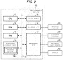
- FIG. 2 is a block diagram illustrating a circuit configuration of registration device 10.
- the registration device 10 includes a central processing unit (CPU) 11, a read-only memory (ROM) 12, a random-access memory (RAM) 13, an auxiliary storage unit 14, a touch panel 15, a printer interface (printer I/F) 16, and an apparatus interface (apparatus I/F) 17, and a bus 18.
- CPU central processing unit
- ROM read-only memory
- RAM random-access memory
- auxiliary storage unit 14 a touch panel 15, a printer interface (printer I/F) 16, and an apparatus interface (apparatus I/F) 17, and a bus 18.
- the CPU 11, the ROM 12, the RAM 13, and the auxiliary storage unit 14 are connected to each other through the bus 18, thereby, configuring a computer which controls the registration device 10.
- the CPU 11 corresponds to a central processor unit of the computer.
- the CPU 11 controls each element of the registration device 10 so as to realize various operations of the registration device 10, based on an operating system, middleware, and an application program which can be stored in the ROM 12 and the RAM 13.
- ROM 12 stores the operating system. There is also a case where the ROM 12 stores the middleware or the application program. In addition, there is also a case where the ROM 12 stores data which is referred to when the CPU 11 performs various types of processing.
- RAM 13 stores data which is referred to when the CPU 11 performs various types of processing. Furthermore, the RAM 13 stores data which is temporarily used when the CPU 11 performs various types of processing, and is used as a so-called work area. A part of a storage area of the RAM 13 is used as a merchandise list area for managing information on merchandise whose sales registration is to be performed.
- the auxiliary storage unit 14 corresponds to an auxiliary storage unit of the computer.
- an electrically erasable programmable read-only memory (EEPROM), a hard disk drive, a solid state drive (SSD), or the like can be used as the auxiliary storage unit 14.
- the auxiliary storage unit 14 stores data which is used when the CPU 11 performs various types of processing or data which is generated by processing of the CPU 11.
- the auxiliary storage unit 14 stores programs such as the middleware and the application program.
- a program which can be stored in the auxiliary storage unit 14 includes a printer driver program 14a. Instructions for the CPU 11 to operate receipt printer 20 are stored in the printer driver program 14a.
- the registration device 10 may be transferred to an end user without the printer driver program 14a being stored in the auxiliary storage unit 14.
- the printer driver program 14a may be stored in a removable storage medium and separately transferred to the end user, or transferred via a network. Subsequent to the transfers of the registration device 10 and the printer driver program 14a, the user or the like may store the printer driver program 14a in the auxiliary storage unit 14 of the registration device 10.
- a magnetic disk, a magneto-optical disk, an optical disk, a semiconductor memory, or the like can be used as the removable storage medium.
- the registration device 10 may also be transferred to the end user with the printer driver program 14a stored in the ROM 12 or the auxiliary storage unit 14.
- the touch panel 15 functions as an input device of the registration device 10 for an operator to input data and a display device for displaying information on the operator.
- the touch panel 15 may be located toward a side (front side of FIG. 1 ) where the operator is located.
- the touch panel 15 may be located on an upper side of the registration device 10, for example, as illustrated in FIG. 1 .
- the printer interface 16 permits data communication between the CPU 11 and the receipt printer 20.
- a conventional device based on an interface standard, such as universal serial bus (USB), can be used as the printer interface 16.
- USB universal serial bus
- the apparatus interface 17 is connected to various apparatuses which are externally attached to the registration device 10, other than the receipt printer 20 (hereinafter, referred to as "external apparatus").
- the customer display 30, the magnetic card reader 40, and the drawer 50 are connected to the apparatus interface 17, and thus, those correspond to the external apparatuses.
- at least a part or all of the customer display 30, the magnetic card reader 40, and the drawer 50 may not be connected to the apparatus interface 17.
- the apparatus interface 17 may be connected to other apparatuses, such as an automatic change machine, a non-contact type integrated chip (IC) card reader, a touch panel, or a bar code reader. That is, types of connected external apparatuses depend on the intended operational form of the registration device 10.
- IC integrated chip
- external apparatuses may not be present or attached depending on the operational form of the registration device 10.
- the apparatus interface 17 permits data communication between the connected apparatus and the CPU 11.
- a conventional device based on an interface standard, such as USB or RS-232C, can be used as the apparatus interface 17.
- the bus 18 connects the CPU 11, the ROM 12, the RAM 13, the auxiliary storage unit 14, the touch panel 15, the printer interface 16, and the apparatus interface 17 to each other.
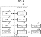
- FIG. 3 is a block diagram illustrating a circuit configuration of the receipt printer 20.
- the receipt printer 20 includes a CPU 21, a ROM 22, a RAM 23, an auxiliary storage unit 24, an operation panel 25, a print unit 26, a communication interface (communication I/F) 27, a near field communication (NFC) unit 28, and a bus 29.
- the CPU 21, the ROM 22, the RAM 23, and the auxiliary storage unit 24 are connected to each other through the bus 29, thereby, configuring a computer which controls the receipt printer 20.
- the CPU 21 corresponds to a central processing unit of the computer.
- the CPU 21 controls each element of the receipt printer 20 so as to realize various operations of the receipt printer 20, based on an operating system, middleware, and an application program which are stored in ROM 22 and RAM 23.
- ROM 22 stores the operating system. There is also a case where the ROM 22 stores the middleware and the application program. In addition, there is also a case where the ROM 22 stores data which is referred to when the CPU 21 performs various types of processing.
- RAM 23 stores data which is referred to when the CPU 21 performs various types of processing. Furthermore, the RAM 23 stores data which is temporarily used when the CPU 21 performs various types of processing, and is used as a so-called work area.
- the auxiliary storage unit 24 corresponds to an auxiliary storage unit of the computer.
- an EEPROM, a hard disk drive, an SSD, or the like can be used as the auxiliary storage unit 24.
- the auxiliary storage unit 24 stores data which is used when the CPU 21 performs various types of processing or data which is generated by processing of the CPU 21. There is also a case where the auxiliary storage unit 24 stores the middleware or the application program. In one or more embodiments, the auxiliary storage unit 24 may not be included in the receipt printer 20.
- the programs which are stored in the ROM 22 or the auxiliary storage unit 24 include a control program described in control processing, which will be described below.
- the receipt printer 20 may be transferred to an end user with the control program stored in the ROM 22 or the auxiliary storage unit 24.
- the receipt printer 20 may be transferred to the end user without the control program stored in the ROM 22 or the auxiliary storage unit 24.
- the control program may be stored in a removable storage medium and separately transferred to the end user, or transferred via a network.
- the end user or the like may store the control program in the auxiliary storage unit 24 of the receipt printer 20.
- a magnetic disk, a magneto-optical disk, an optical disk, a semiconductor memory, or the like can be used as the removable storage medium.
- the operation panel 25 is included on a front surface of the receipt printer 20, for example, as illustrated in FIG. 1 .
- the operation panel 25 includes operation buttons for operating the receipt printer 20, and a display device for displaying an operation mode of the receipt printer 20.
- the print unit 26 prints an arbitrary image on receipt paper (a print medium).
- the print unit 26 may have a conventional printer configuration, including a print head of a thermal printer and a transport mechanism which is configured to transport the receipt paper for printing.
- the print unit 26 prints an image representing content of transaction on the receipt paper (i.e., receipt) and discharges out of the receipt printer 20 from the outlet 20a illustrated in FIG. 1 .
- a print head of any other types of printers, such as a dot impact printer or an ink jet printer may be used for the print head of the print unit 26.
- the print unit 26 corresponds to a printing mechanism which prints an image, inclusive of a text image, on the receipt paper that is an example of a print medium.
- the communication interface 27 allows data communication between the registration device 10 and the CPU 21.
- a conventional device based on an interface standard such as USB or RS-232C can be used as the communication interface 27.
- the NFC unit 28 includes an antenna 28a disposed to face an upper surface of the receipt printer 20, as illustrated in FIG. 1 .
- the NFC unit 28 performs wireless communication with the information terminal 200 close to the antenna 28a by using an NFC communication method.
- the bus 29 connects the CPU 21, the ROM 22, the RAM 23, the auxiliary storage unit 24, the operation panel 25, the print unit 26, the communication interface 27, and the NFC unit 28 to each other.
- Registration device 10 provides, for example, registration processing relating to transactions. If the transaction involves payment, the accounting system 100 further performs payment processing. For example, if the transaction is sales of merchandise, the registration device 10 performs registration of merchandise being sold and generates a list of the sold merchandise for each transaction. After the registration is completed, the registration device 10 performs processing for paying a payment amount relating to the merchandise included in the list.
- the transaction to be registered as registration target is a sale of merchandise between a merchandising store and a customer.
- the customer display 30 displays an image representing information to the customer in accordance with instruction from the registration device 10 when registration processing or payment processing is performed. If card information for the payment processing is required, the magnetic card reader 40 reads the card information recorded in a magnetic card, controlled by an operator, and outputs the card information to the registration device 10.
- the drawer 50 opens in accordance with the instruction from the registration device 10 if withdrawal/storage of money relating to the payment processing is required.
- the registration device 10 transmits receipt data including transaction details and also requests (sends a print request to) the receipt printer 20 to print a receipt.
- the print request is performed by the CPU 11 of the registration device 10 executing a printer driver program 14a.
- the communication interface 27 of the receipt printer 20 receives the print request. Then, the CPU 21 instructs the print unit 26 to print a paper receipt if a predetermined standby time has expired without performing any NFC communication with the information terminal 200 or if a print instruction is given by a predetermined button operation or the like on the operation panel 25. That is, the CPU 21 controls the print unit 26 such that a transaction receipt is printed on a print medium according to the receipt data received by the communication interface 27.
- NFC communication with the information terminal 200 can be established prior to the expiration of the predetermined standby time or the print instruction being given, then CPU 21 performs wireless transmission of electronic receipt data to the information terminal 200. That is, the CPU 21 generates the electronic receipt data based on the receipt data received by the communication interface 27, and wirelessly transmits the electronic receipt data via the near field communication unit 28 to the information terminal 200.
- the CPU 21 switches the receipt printer 20 from the standby mode to a maintenance mode.
- the maintenance mode CPU 21 performs control processing based on a control program stored in ROM 22 or auxiliary storage unit 24.
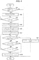
- FIG. 4 is a flowchart of a control processing which can be performed by the CPU 21.
- the CPU 21 determines whether or not an external collection flag stored in the auxiliary storage unit 24 is set to "1".
- the external collection flag represents whether or not maintenance data of apparatuses other than the receipt printer 20 will be collected, and a state “1" represents the maintenance data of the apparatuses other than the receipt printer 20 will be collected.
- the CPU 21 sets the external collection flag to "0” or “1", according to a predetermined operation, such as a button operation or the like on the operation panel 25. Either "0" or “1” may be a default value for the external collection flag.
- the CPU 21 determines that an answer is Yes and proceeds to Act 2.
- the CPU 21 requests the registration device 10 to transmit external maintenance data. Specifically, the CPU 21 transmits a command from the communication interface 27 to the registration device 10 to request the external maintenance data. As the command is received by the printer interface 16 of the registration device 10, the request is accepted by the registration device 10. Subsequently, the CPU 11 of the registration device 10 starts collection processing, which will be described below, according to the printer driver program 14a. Thus, the collection processing is performed by a printer driver as the CPU 11 executes the printer driver program 14a. That is, the printer driver program 14a starts the collection processing after receiving the request. Hence, as the CPU 21 performs the control processing based on the control program, a computer, which comprises the CPU 21, functions as a request unit which requests the printer driver to transmit the maintenance information.
- FIG. 5 is a flowchart of a collection processing which can be performed by the CPU 11.
- the CPU 11 collects maintenance information of the registration device 10, and stores the maintenance information in the RAM 13 or the auxiliary storage unit 14.
- the maintenance information is data relating to maintenance of the registration device 10.
- Types of data which the CPU 11 collects as the maintenance information of the registration device 10 may be arbitrarily determined by, for example, a designer, a creator, or the like of the printer driver program 14a.
- the maintenance information of the registration device 10 may include a version number of the operation system, a version number of the printer driver program 14a, a cumulative time for which the registration device 10 has been in operation, a property/condition of the auxiliary storage unit 14, or the like.
- the computer which comprises CPU 11, functions as an acquisition unit which acquires the maintenance information of the registration device 10.
- the CPU 11 determines whether or not there are any other external apparatuses.
- the customer display 30, the magnetic card reader 40, and the drawer 50 are external apparatuses. In this case, the CPU 11 determines that the answer is Yes and proceeds to Act 23.
- the CPU 11 collects maintenance information of the external apparatuses and stores the maintenance information in the RAM 13 or the auxiliary storage unit 14.
- maintenance information for the external apparatuses is data relating to maintenance of the external apparatuses.
- Types of data which the CPU 11 collects as the maintenance information of the external apparatuses may be arbitrarily determined by, for example, a designer, a creator, or the like of the printer driver program 14a.
- the maintenance information of the external apparatuses may be cumulative time for which the customer display 30 has been performs display, a cumulative number of readings by the magnetic card reader 40, a cumulative number of releases of the drawer 50, any abnormality (error) occurrences for each apparatus, or the like.
- the CPU 11 proceeds to Act 24. If there are no external apparatuses, the CPU 11 determines that the answer is No in Act 22 and bypasses Act 23 to proceed to Act 24.
- the CPU 11 generates external maintenance data. Specifically, the CPU 11 includes the maintenance information of the registration device 10 (stored in Act 21) in the external maintenance data. In addition, if the maintenance information of the external apparatuses (stored in Act 23) exists, the CPU 11 also includes the maintenance information of the external apparatuses in the external maintenance data.
- the CPU 11 instructs the printer interface 16 to transmit the external maintenance data generated as described above, and then ends the collection processing.
- the printer interface 16 transmits the external maintenance data to the receipt printer 20, according to the instruction. If the external maintenance data is transmitted to the receipt printer 20, the communication interface 27 receives the external maintenance data.
- the printer interface 16 is an example of a communication device which transmits the maintenance information of the registration device 10 to the receipt printer 20.
- the computer which comprises the CPU 11, functions as a transmission control unit which controls the printer interface 16 to transmit the maintenance information of the registration device 10.
- the communication interface 27 is an example of a reception unit.
- the CPU 21 waits for reception of the external maintenance data. If the external maintenance data is received by the communication interface 27 as described above, the CPU 21 determines that the answer is Yes, and proceeds to Act 4.
- the CPU 21 stores the external maintenance data received by the communication interface 27 in the RAM 23 or the auxiliary storage unit 24. After that, the CPU 21 proceeds to Act 5. If it is determined that the answer is No in Act 1 since the external collection flag is set to "0", the CPU 21 passes Act 2 to Act 4 to proceed to Act 5.
- the CPU 21 collects maintenance information of the receipt printer 20 and stores the maintenance information in the RAM 23 or the auxiliary storage unit 24.
- Types of data which the CPU 21 collects as the maintenance information of the receipt printer 20 may be arbitrarily determined by, for example, a designer, a creator, or the like of the control program for the CPU 21.
- the maintenance information of the receipt printer 20 may be a total print volume, a print volume generated by using attached print head, or the like.
- the CPU 21 generates total maintenance data. Specifically, the CPU 21 includes the maintenance information of the receipt printer 20 stored in Act 5 in the total maintenance data. If the external maintenance data is stored in Act 4, the CPU 21 includes the external maintenance data in the external maintenance data.
- the CPU 21 determines whether or not transmission is requested. If the transmission is not requested, the CPU 21 determines that the answer is No and proceeds to Act 8.
- the CPU 21 determines whether or not print instruction is given. If the print instruction is not given by a predetermined button operation on the operation panel 25, the CPU 21 determines that the answer is No and proceeds to Act 9.
- the CPU 21 determines whether or not the predetermined standby time is expired. If the predetermined standby time is not expired, the CPU 21 returns to Act 7.
- the CPU 21 waits for whether the transmission is requested, the print instruction is given, or the predetermined standby time is expired.
- the CPU 21 instructs the print unit 26 to print the maintenance sheet. Specifically, the CPU 21 instructs the print unit 26 to print an image representing the total maintenance data generated in Act 6.
- the print unit 26 prints the maintenance sheet by printing the image on a print medium, according to the instruction. That is, the maintenance sheet is obtained by printing the image representing the maintenance data on the print medium.
- the image may be an image of a character string or the like representing the maintenance data such that the maintenance worker can directly understand, or may be an image which is mechanically readable by using a QR code® or the like.
- the computer which comprises the CPU 21, functions as a control unit which controls the print unit 26 to print the maintenance information of the registration device 10, the receipt printer 20, and the external apparatuses. If printing of the maintenance sheet ends, the CPU 21 ends the control processing illustrated in FIG. 4 .
- the information terminal 200 is moved in close proximity to the receipt printer 20, when the CPU 21 is in the standby mode of Act 7 to Act 9. Then, the information terminal 200 can perform the NFC communication with the NFC unit 28.
- the maintenance worker keeps the information terminal 200 in the maintenance mode.
- the information terminal 200 may automatically start processing for maintenance by an operation of the operating system or the firmware.
- the information terminal 200 requests the receipt printer 20 to transmit the external maintenance data through the NFC communication. The request is received by the NFC unit 28.
- the CPU 21 in the receipt printer 20 determines that the answer is Yes in Act 7 and proceeds to Act 11, as the request is received by the NFC unit 28.
- the CPU 21 wirelessly transmits the total maintenance data generated in Act 6 from the NFC unit 28. If the transmission is completed, the CPU 21 ends the control processing illustrated in FIG. 4 .
- the computer which comprises the CPU 21, and the NFC unit 28, enable wireless communication to transmit the total maintenance data to the information terminal 200.
- the printer driver collects the maintenance information of the registration device 10, and transmits the maintenance information to the receipt printer 20, according to the request from the receipt printer 20 in the maintenance mode.
- the receipt printer 20 prints a maintenance sheet in which the maintenance information of the registration device 10 is represented together with the maintenance information of the receipt printer 20 on the receipt printer 20.
- a maintenance worker can confirm both the maintenance information of the registration device 10 and the maintenance information of the receipt printer 20 on the maintenance sheet.
- the maintenance worker does not need to perform any operation with the registration device 10 other than setting an operation mode of the receipt printer 20 to the maintenance mode.
- the printer driver further collects the maintenance information of the external apparatuses, and transmits this maintenance information to the receipt printer 20.
- the receipt printer 20 can print a maintenance sheet including the maintenance information of the external apparatuses together with the maintenance information of the registration device 10 and the receipt printer 20. Thereby, the maintenance worker can confirm the maintenance information of the registration device 10, the receipt printer 20, and the external apparatuses on the maintenance sheet. At this time, the maintenance worker cannot perform any operation with the external apparatus.
- the receipt printer 20 transmits total maintenance data including the maintenance information of the registration device 10 and the maintenance information of the receipt printer 20, or the total maintenance data further including the maintenance information of the external apparatuses to the information terminal 200, instead of printing the maintenance sheet. Thereby, the maintenance worker can confirm the maintenance information of the registration device 10, the receipt printer 20, and the external apparatuses in the information terminal 200.
- the receipt printer 20 does not request the printer driver to collect the maintenance information. Thereby, if only the maintenance information of the receipt printer 20 may be collected, the maintenance worker can set the external collection flag to "0" only for the receipt printer 20.
- the embodiment can be variously modified, for example, as follows.
- a printer which prints a printed material other than a sheet can also perform the substantially the same operation as the receipt printer 20.
- An apparatus which performs processing other than the registration processing of a sales transaction can also perform substantially the same operation as the registration device 10.
- the CPU 21 may instruct the print unit 26 to print a plurality of maintenance sheets. That is, the CPU 21 may instruct the print unit 26 to print, for example m, three maintenance sheets which separately represent the maintenance information of the registration device 10, the receipt printer 20, and the external apparatuses, respectively. Alternatively, the CPU 21 may instruct the print unit 26 to print, for example, a maintenance sheet which represents the maintenance information of two of the registration device 10, the receipt printer 20, and the external apparatuses and a maintenance sheet which represents the maintenance information of the other of the registration device 10, the receipt printer 20, and the external apparatuses. The CPU 21 may control the print unit 26 to print the maintenance information of one of the registration device 10, the receipt printer 20, and the external apparatuses on a plurality of print media.
- printer driver it is also possible for the printer driver to be provided in a dedicated computer that is mounted in an apparatus along with another computer which controls other operations of the apparatus such as operations of the registration device 10.
- any other communication methods other than the NFC communication method may be used for the communication between the receipt printer 20 and the information terminal 200.
- the NFC unit 28 or the antenna 28a may be externally attached to the receipt printer 20 without being embedded therein.
- the CPU 21 may perform Act 10 and Act 11 simultaneously, and may provide instructions to print the maintenance sheet and transmit the total maintenance data.
Landscapes
- Engineering & Computer Science (AREA)
- Theoretical Computer Science (AREA)
- General Engineering & Computer Science (AREA)
- Human Computer Interaction (AREA)
- Physics & Mathematics (AREA)
- General Physics & Mathematics (AREA)
- Accessory Devices And Overall Control Thereof (AREA)
- Cash Registers Or Receiving Machines (AREA)
Abstract
Description
- The present invention relates to printing technologies in general and embodiments described herein relate in particular to a print system or apparatus, a printer driver, and a program.
- A printer with a maintenance mode is known. In a maintenance mode, this type of printer may have a function of printing out maintenance information of the printer.
- In addition, an apparatus other than a printer connected to the printer may have a function of generating an image representing maintenance information of the apparatus and making the printer print the image.
- According to the function, a maintenance worker or the like can obtain a printed material representing maintenance information of a printer and an apparatus connected to the printer. However, in order to obtain the printed material representing the maintenance information of the printer and the apparatus connected to the printer, the maintenance worker or the like has to operate each of the printer and the apparatus.
- Under such circumstances, a print system, a printer driver, and a program which can easily print maintenance information of a printer and an apparatus other than the printer, are required.
- To solve such problems, there is provided a printing apparatus, comprising:
- a printer including a first processor and a printing unit that is capable of printing on a print medium; and
- a registration device connected to the printer and including a second processor and storing a printer driver, wherein
- the printer stores a control program that when executed by the first processor causes:
- the printer to request first maintenance information of the registration device from the printer driver,
- the printer to acquire second maintenance information of the printer, and
- the printer to output at least one of the first and second maintenance information.
- Preferably, when executed, the control program causes the printer to store the first maintenance information in a storage medium.
- Preferably still, the printing unit is one of a thermal printing unit, an inkjet printing unit, or a dot impact printing unit.
- Preferably yet, the registration device is a point-of-sale terminal.
- Suitably, the printing apparatus further comprises:
- an external apparatus connected to the registration device, wherein
- the printer driver is configured to acquire third maintenance information of the external apparatus and transmit the third maintenance information to the printer.
- In the above printing apparatus, the external apparatus is preferably one of a customer display, a magnetic card reader, or a cash register drawer.
- Suitably, the control program, when executed by the first processor, further causes the printer to output the third maintenance information.
- In the above printing apparatus, the output of at least one of the first and second maintenance information is by printing at least one of the first and second maintenance information on the print medium.
- Typically, the printing apparatus further comprises:
- a wireless communication unit configured to wirelessly transmit data including at least one of the first and second maintenance information to an external information terminal, wherein
- the output of at least one of the first and second maintenance information is by transmission of data including at least one of the first and second maintenance information to the external information terminal.
- In the above printing apparatus, the wireless communication unit is preferably a near field communication interface unit.
- Also in the above printing apparatus, the near field communication unit is suitably incorporated within the printer.
- Preferably, the printer includes an operation panel including a button that when pressed for a predetermined time period while the printer is in a standby mode causes the printer to enter a maintenance mode during which the control program is executed by the first processor.
- The invention also relates to a printer driver stored in a registration device connected to a printer, the printer driver being configured to:
- control the printer to print information on a print medium;
- acquire first maintenance information of the registration device upon a request being received from the printer; and
- transmit first maintenance information from the registration device to the printer after the first maintenance information has been acquired.
- Preferably, the first maintenance information includes at least one of a version number of the printer driver, a version number of an operating system running on the registration device, or a cumulative operation time of the registration device.
- Preferably still, the printer driver is further configured to:
- acquire second maintenance information of an external apparatus connected to the registration device upon the request being received from the printer; and
- transmit the second maintenance information from the registration device to the printer.
- In the above printer driver, the registration device is preferably a point-of-sale terminal.
- The invention further relates to a non-transitory computer readable medium storing program instructions for a printer driver that when executed by a processor in a registration device connected to a printer causes the registration device to perform the steps to:
- control the printer to print information on a print medium;
- acquire first maintenance information of the registration device upon a request being received from the printer; and
- transmit first maintenance information from the registration device to the printer after the first maintenance information has been acquired.
- Preferably, the first maintenance information includes at least one of a version number of the printer driver, a version number of an operating system running on the registration device, or a cumulative operation time of the registration device.
- Preferably still, the printer driver further causes the registration device to:
- acquire second maintenance information of an external apparatus connected to the registration device upon the request being received from the printer; and
- transmit the second maintenance information from the registration device to the printer.
- In the above non-transitory computer readable medium, the registration device is preferably a point-of-sale terminal.
- The invention further relates to a computer program product comprising program code means stored in the non-transitory computer readable medium as defined above for performing the steps when the program product is run on a computer.
- The above and other objects, features and advantages of the present invention will be made apparent from the following description of the preferred embodiments, given as non-limiting examples, with reference to the accompanying drawings, in which:
-
FIG. 1 is a perspective view illustrating a configuration of an accounting system according to an embodiment. -
FIG. 2 is a block diagram illustrating a schematic circuit configuration of a registration device. -
FIG. 3 is a block diagram illustrating a circuit configuration of a receipt printer. -
FIG. 4 is a flowchart of control processing which is performed by a central processor unit (CPU). -
FIG. 5 is a flowchart of collection processing which is performed by a CPU. - In general, according to one embodiment, a printing apparatus comprises a printer including a first processor and a printing unit that is capable of printing on a print medium. The printing apparatus also comprises a registration device connected to the printer. The registration device includes a second processor and a printer driver. The printer stores a control program that when executed by the first processor causes the printer to request the printer driver to cause the printer to a request unit that is included in the printer and requests the printer driver to cause acquisition of for first maintenance information by the registration device and then transmit the first maintenance information from the registration device to the printer, which represents maintenance information of the registration device, the printer to collect second maintenance information, the second maintenance information being which represents maintenance information of the printer, and the printer to output at least one of the first and second maintenance information.
- Hereinafter, a specific embodiment will be described with reference to the drawings, using an example of an accounting system into which a print system is incorporated. This example is used for the purposes of illustrations only. Accordingly, the scope of the invention should not be considered limited to those specific applications.
-
FIG. 1 is a perspective view illustrating a configuration of anaccounting system 100. - The
accounting system 100 includes aregistration device 10, atouch panel 15, areceipt printer 20, acustomer display 30, amagnetic card reader 40, and adrawer 50. - The
registration device 10 registers content of transaction that a customer performs (hereinafter, referred to as "target of registration"). The transaction is typically sales of merchandise. A point-of-sale (POS) terminal or an electronic cash register is typically used as theregistration device 10. Theregistration device 10 requests printing of a receipt representing the content of transaction to thereceipt printer 20. - The
receipt printer 20 prints a paper receipt according to the request from theregistration device 10 or wirelessly transmits an electronic sheet data to aninformation terminal 200. Alternatively, thereceipt printer 20 has a maintenance mode as one of its possible operation modes. In the maintenance mode, thereceipt printer 20 prints a maintenance sheet listing maintenance information, or wirelessly transmits maintenance data including the maintenance information to aninformation terminal 200. Thereceipt printer 20 includes anoutlet 20a, anoperation panel 25, andantenna 28a, which will be described below. Theinformation terminal 200 accepts, manages, and displays the electronic sheet data and maintenance information that thereceipt printer 20 wirelessly transmits. Theinformation terminal 200 is typically a mobile device (e.g., a laptop computer, a smart phone, a tablet computer, or other mobile device). However, theinformation terminal 200 may be any other type of computing device. - The
customer display 30 is provided toward a side (rear side ofFIG. 1 ) at which the customer is located. Thecustomer display 30 displays information to the customer according to instruction from theregistration device 10. A conventional display device such as a fluorescent tube display or a liquid crystal display can be used as thecustomer display 30. - The
magnetic card reader 40 reads information magnetically recorded in a magnetic card. Themagnetic card reader 40 outputs the information to theregistration device 10. - The
drawer 50 stores money or the like in an internal storage tray. Thedrawer 50 opens the storage tray according to the instruction from theregistration device 10 such that the money can be stored and withdrawn. -
FIG. 2 is a block diagram illustrating a circuit configuration ofregistration device 10. - The
registration device 10 includes a central processing unit (CPU) 11, a read-only memory (ROM) 12, a random-access memory (RAM) 13, anauxiliary storage unit 14, atouch panel 15, a printer interface (printer I/F) 16, and an apparatus interface (apparatus I/F) 17, and abus 18. - In the
registration device 10, theCPU 11, theROM 12, theRAM 13, and theauxiliary storage unit 14 are connected to each other through thebus 18, thereby, configuring a computer which controls theregistration device 10. - The
CPU 11 corresponds to a central processor unit of the computer. TheCPU 11 controls each element of theregistration device 10 so as to realize various operations of theregistration device 10, based on an operating system, middleware, and an application program which can be stored in theROM 12 and theRAM 13. -
ROM 12 stores the operating system. There is also a case where theROM 12 stores the middleware or the application program. In addition, there is also a case where theROM 12 stores data which is referred to when theCPU 11 performs various types of processing. -
RAM 13 stores data which is referred to when theCPU 11 performs various types of processing. Furthermore, theRAM 13 stores data which is temporarily used when theCPU 11 performs various types of processing, and is used as a so-called work area. A part of a storage area of theRAM 13 is used as a merchandise list area for managing information on merchandise whose sales registration is to be performed. - The
auxiliary storage unit 14 corresponds to an auxiliary storage unit of the computer. For example, an electrically erasable programmable read-only memory (EEPROM), a hard disk drive, a solid state drive (SSD), or the like can be used as theauxiliary storage unit 14. Theauxiliary storage unit 14 stores data which is used when theCPU 11 performs various types of processing or data which is generated by processing of theCPU 11. There is also a case where theauxiliary storage unit 14 stores programs such as the middleware and the application program. A program which can be stored in theauxiliary storage unit 14 includes aprinter driver program 14a. Instructions for theCPU 11 to operatereceipt printer 20 are stored in theprinter driver program 14a. In general, theregistration device 10 may be transferred to an end user without theprinter driver program 14a being stored in theauxiliary storage unit 14. Theprinter driver program 14a may be stored in a removable storage medium and separately transferred to the end user, or transferred via a network. Subsequent to the transfers of theregistration device 10 and theprinter driver program 14a, the user or the like may store theprinter driver program 14a in theauxiliary storage unit 14 of theregistration device 10. In one or more embodiments, a magnetic disk, a magneto-optical disk, an optical disk, a semiconductor memory, or the like can be used as the removable storage medium. However, theregistration device 10 may also be transferred to the end user with theprinter driver program 14a stored in theROM 12 or theauxiliary storage unit 14. - The
touch panel 15 functions as an input device of theregistration device 10 for an operator to input data and a display device for displaying information on the operator. Thetouch panel 15 may be located toward a side (front side ofFIG. 1 ) where the operator is located. Thetouch panel 15 may be located on an upper side of theregistration device 10, for example, as illustrated inFIG. 1 . - The
printer interface 16 permits data communication between theCPU 11 and thereceipt printer 20. A conventional device based on an interface standard, such as universal serial bus (USB), can be used as theprinter interface 16. - The
apparatus interface 17 is connected to various apparatuses which are externally attached to theregistration device 10, other than the receipt printer 20 (hereinafter, referred to as "external apparatus"). In the present embodiment, thecustomer display 30, themagnetic card reader 40, and thedrawer 50 are connected to theapparatus interface 17, and thus, those correspond to the external apparatuses. However, in one or more embodiments, at least a part or all of thecustomer display 30, themagnetic card reader 40, and thedrawer 50 may not be connected to theapparatus interface 17. In addition, theapparatus interface 17 may be connected to other apparatuses, such as an automatic change machine, a non-contact type integrated chip (IC) card reader, a touch panel, or a bar code reader. That is, types of connected external apparatuses depend on the intended operational form of theregistration device 10. In one or more embodiments, external apparatuses may not be present or attached depending on the operational form of theregistration device 10. Theapparatus interface 17 permits data communication between the connected apparatus and theCPU 11. A conventional device based on an interface standard, such as USB or RS-232C, can be used as theapparatus interface 17. - The
bus 18 connects theCPU 11, theROM 12, theRAM 13, theauxiliary storage unit 14, thetouch panel 15, theprinter interface 16, and theapparatus interface 17 to each other. -
FIG. 3 is a block diagram illustrating a circuit configuration of thereceipt printer 20. - The
receipt printer 20 includes aCPU 21, aROM 22, aRAM 23, anauxiliary storage unit 24, anoperation panel 25, aprint unit 26, a communication interface (communication I/F) 27, a near field communication (NFC)unit 28, and abus 29. - In the
receipt printer 20, theCPU 21, theROM 22, theRAM 23, and theauxiliary storage unit 24 are connected to each other through thebus 29, thereby, configuring a computer which controls thereceipt printer 20. - The
CPU 21 corresponds to a central processing unit of the computer. TheCPU 21 controls each element of thereceipt printer 20 so as to realize various operations of thereceipt printer 20, based on an operating system, middleware, and an application program which are stored inROM 22 andRAM 23. -
ROM 22 stores the operating system. There is also a case where theROM 22 stores the middleware and the application program. In addition, there is also a case where theROM 22 stores data which is referred to when theCPU 21 performs various types of processing. -
RAM 23 stores data which is referred to when theCPU 21 performs various types of processing. Furthermore, theRAM 23 stores data which is temporarily used when theCPU 21 performs various types of processing, and is used as a so-called work area. - The
auxiliary storage unit 24 corresponds to an auxiliary storage unit of the computer. For example, an EEPROM, a hard disk drive, an SSD, or the like can be used as theauxiliary storage unit 24. Theauxiliary storage unit 24 stores data which is used when theCPU 21 performs various types of processing or data which is generated by processing of theCPU 21. There is also a case where theauxiliary storage unit 24 stores the middleware or the application program. In one or more embodiments, theauxiliary storage unit 24 may not be included in thereceipt printer 20. - The programs which are stored in the
ROM 22 or theauxiliary storage unit 24 include a control program described in control processing, which will be described below. In general, thereceipt printer 20 may be transferred to an end user with the control program stored in theROM 22 or theauxiliary storage unit 24. However, thereceipt printer 20 may be transferred to the end user without the control program stored in theROM 22 or theauxiliary storage unit 24. In this case, the control program may be stored in a removable storage medium and separately transferred to the end user, or transferred via a network. Subsequent to the transfers of thereceipt printer 20 and the control program, the end user or the like may store the control program in theauxiliary storage unit 24 of thereceipt printer 20. In one or more embodiments, a magnetic disk, a magneto-optical disk, an optical disk, a semiconductor memory, or the like can be used as the removable storage medium. - The
operation panel 25 is included on a front surface of thereceipt printer 20, for example, as illustrated inFIG. 1 . Theoperation panel 25 includes operation buttons for operating thereceipt printer 20, and a display device for displaying an operation mode of thereceipt printer 20. - The
print unit 26 prints an arbitrary image on receipt paper (a print medium). Theprint unit 26 may have a conventional printer configuration, including a print head of a thermal printer and a transport mechanism which is configured to transport the receipt paper for printing. Theprint unit 26 prints an image representing content of transaction on the receipt paper (i.e., receipt) and discharges out of thereceipt printer 20 from theoutlet 20a illustrated inFIG. 1 . A print head of any other types of printers, such as a dot impact printer or an ink jet printer may be used for the print head of theprint unit 26. Theprint unit 26 corresponds to a printing mechanism which prints an image, inclusive of a text image, on the receipt paper that is an example of a print medium. - The
communication interface 27 allows data communication between theregistration device 10 and theCPU 21. A conventional device based on an interface standard such as USB or RS-232C can be used as thecommunication interface 27. - The
NFC unit 28 includes anantenna 28a disposed to face an upper surface of thereceipt printer 20, as illustrated inFIG. 1 . TheNFC unit 28 performs wireless communication with theinformation terminal 200 close to theantenna 28a by using an NFC communication method. - The
bus 29 connects theCPU 21, theROM 22, theRAM 23, theauxiliary storage unit 24, theoperation panel 25, theprint unit 26, thecommunication interface 27, and theNFC unit 28 to each other. - Next, an operation of the
accounting system 100 configured as described above will be described below, using an example of contents of certain types of processing. Contents of other types of processing may be used without departing from the scope of the invention. - In the
accounting system 100, an operation relating to accounting for a transaction is performed.Registration device 10 provides, for example, registration processing relating to transactions. If the transaction involves payment, theaccounting system 100 further performs payment processing. For example, if the transaction is sales of merchandise, theregistration device 10 performs registration of merchandise being sold and generates a list of the sold merchandise for each transaction. After the registration is completed, theregistration device 10 performs processing for paying a payment amount relating to the merchandise included in the list. Hereinafter, description will be made by assuming that the transaction to be registered as registration target is a sale of merchandise between a merchandising store and a customer. - The
customer display 30 displays an image representing information to the customer in accordance with instruction from theregistration device 10 when registration processing or payment processing is performed. If card information for the payment processing is required, themagnetic card reader 40 reads the card information recorded in a magnetic card, controlled by an operator, and outputs the card information to theregistration device 10. Thedrawer 50 opens in accordance with the instruction from theregistration device 10 if withdrawal/storage of money relating to the payment processing is required. - If the payment has been completed, the
registration device 10 transmits receipt data including transaction details and also requests (sends a print request to) thereceipt printer 20 to print a receipt. The print request is performed by theCPU 11 of theregistration device 10 executing aprinter driver program 14a. - The
communication interface 27 of thereceipt printer 20 receives the print request. Then, theCPU 21 instructs theprint unit 26 to print a paper receipt if a predetermined standby time has expired without performing any NFC communication with theinformation terminal 200 or if a print instruction is given by a predetermined button operation or the like on theoperation panel 25. That is, theCPU 21 controls theprint unit 26 such that a transaction receipt is printed on a print medium according to the receipt data received by thecommunication interface 27. However, if NFC communication with theinformation terminal 200 can be established prior to the expiration of the predetermined standby time or the print instruction being given, thenCPU 21 performs wireless transmission of electronic receipt data to theinformation terminal 200. That is, theCPU 21 generates the electronic receipt data based on the receipt data received by thecommunication interface 27, and wirelessly transmits the electronic receipt data via the nearfield communication unit 28 to theinformation terminal 200. - Thus, when the
receipt printer 20 is in a standby mode or the like, if an operation such as long pressing of a button on theoperation panel 25 is performed, theCPU 21 switches thereceipt printer 20 from the standby mode to a maintenance mode. In the maintenance mode,CPU 21 performs control processing based on a control program stored inROM 22 orauxiliary storage unit 24. -
FIG. 4 is a flowchart of a control processing which can be performed by theCPU 21. - In
Act 1, theCPU 21 determines whether or not an external collection flag stored in theauxiliary storage unit 24 is set to "1". The external collection flag represents whether or not maintenance data of apparatuses other than thereceipt printer 20 will be collected, and a state "1" represents the maintenance data of the apparatuses other than thereceipt printer 20 will be collected. TheCPU 21 sets the external collection flag to "0" or "1", according to a predetermined operation, such as a button operation or the like on theoperation panel 25. Either "0" or "1" may be a default value for the external collection flag. Here, when the external collection flag is set to "1", theCPU 21 determines that an answer is Yes and proceeds to Act 2. - In Act 2, the
CPU 21 requests theregistration device 10 to transmit external maintenance data. Specifically, theCPU 21 transmits a command from thecommunication interface 27 to theregistration device 10 to request the external maintenance data. As the command is received by theprinter interface 16 of theregistration device 10, the request is accepted by theregistration device 10. Subsequently, theCPU 11 of theregistration device 10 starts collection processing, which will be described below, according to theprinter driver program 14a. Thus, the collection processing is performed by a printer driver as theCPU 11 executes theprinter driver program 14a. That is, theprinter driver program 14a starts the collection processing after receiving the request. Hence, as theCPU 21 performs the control processing based on the control program, a computer, which comprises theCPU 21, functions as a request unit which requests the printer driver to transmit the maintenance information. -
FIG. 5 is a flowchart of a collection processing which can be performed by theCPU 11. - In
Act 21, theCPU 11 collects maintenance information of theregistration device 10, and stores the maintenance information in theRAM 13 or theauxiliary storage unit 14. Here, the maintenance information is data relating to maintenance of theregistration device 10. Types of data which theCPU 11 collects as the maintenance information of theregistration device 10 may be arbitrarily determined by, for example, a designer, a creator, or the like of theprinter driver program 14a. For example, the maintenance information of theregistration device 10 may include a version number of the operation system, a version number of theprinter driver program 14a, a cumulative time for which theregistration device 10 has been in operation, a property/condition of theauxiliary storage unit 14, or the like. Hence, as theCPU 11 performs the control processing based on theprinter driver program 14a, the computer, which comprisesCPU 11, functions as an acquisition unit which acquires the maintenance information of theregistration device 10. - In
Act 22, theCPU 11 determines whether or not there are any other external apparatuses. In the present embodiment, thecustomer display 30, themagnetic card reader 40, and thedrawer 50 are external apparatuses. In this case, theCPU 11 determines that the answer is Yes and proceeds to Act 23. - In
Act 23, theCPU 11 collects maintenance information of the external apparatuses and stores the maintenance information in theRAM 13 or theauxiliary storage unit 14. Here, maintenance information for the external apparatuses is data relating to maintenance of the external apparatuses. Types of data which theCPU 11 collects as the maintenance information of the external apparatuses may be arbitrarily determined by, for example, a designer, a creator, or the like of theprinter driver program 14a. For example, the maintenance information of the external apparatuses may be cumulative time for which thecustomer display 30 has been performs display, a cumulative number of readings by themagnetic card reader 40, a cumulative number of releases of thedrawer 50, any abnormality (error) occurrences for each apparatus, or the like. - If collection and storage of the maintenance information of the external apparatuses has been completed, the
CPU 11 proceeds toAct 24. If there are no external apparatuses, theCPU 11 determines that the answer is No inAct 22 and bypassesAct 23 to proceed toAct 24. - In
Act 24, theCPU 11 generates external maintenance data. Specifically, theCPU 11 includes the maintenance information of the registration device 10 (stored in Act 21) in the external maintenance data. In addition, if the maintenance information of the external apparatuses (stored in Act 23) exists, theCPU 11 also includes the maintenance information of the external apparatuses in the external maintenance data. - In
Act 25, theCPU 11 instructs theprinter interface 16 to transmit the external maintenance data generated as described above, and then ends the collection processing. Theprinter interface 16 transmits the external maintenance data to thereceipt printer 20, according to the instruction. If the external maintenance data is transmitted to thereceipt printer 20, thecommunication interface 27 receives the external maintenance data. Hence, theprinter interface 16 is an example of a communication device which transmits the maintenance information of theregistration device 10 to thereceipt printer 20. As theCPU 11 performs the control processing based on theprinter driver program 14a, the computer, which comprises theCPU 11, functions as a transmission control unit which controls theprinter interface 16 to transmit the maintenance information of theregistration device 10. Thereby, a function as a transmission unit which transmits the maintenance information of theregistration device 10 to thereceipt printer 20 is realized by cooperation of the computer having theCPU 11 as a central unit and theprinter interface 16. In addition, thecommunication interface 27 is an example of a reception unit. - Thus, the
CPU 21 of thereceipt printer 20 ends Act 2 ofFIG. 4 , and thereafter, proceeds to Act 3. - In Act 3, the
CPU 21 waits for reception of the external maintenance data. If the external maintenance data is received by thecommunication interface 27 as described above, theCPU 21 determines that the answer is Yes, and proceeds to Act 4. - In Act 4, the
CPU 21 stores the external maintenance data received by thecommunication interface 27 in theRAM 23 or theauxiliary storage unit 24. After that, theCPU 21 proceeds to Act 5. If it is determined that the answer is No inAct 1 since the external collection flag is set to "0", theCPU 21 passes Act 2 to Act 4 to proceed to Act 5. - In Act 5, the
CPU 21 collects maintenance information of thereceipt printer 20 and stores the maintenance information in theRAM 23 or theauxiliary storage unit 24. Types of data which theCPU 21 collects as the maintenance information of thereceipt printer 20 may be arbitrarily determined by, for example, a designer, a creator, or the like of the control program for theCPU 21. For example, the maintenance information of thereceipt printer 20 may be a total print volume, a print volume generated by using attached print head, or the like. - In Act 6, the
CPU 21 generates total maintenance data. Specifically, theCPU 21 includes the maintenance information of thereceipt printer 20 stored in Act 5 in the total maintenance data. If the external maintenance data is stored in Act 4, theCPU 21 includes the external maintenance data in the external maintenance data. - I Act 7, the
CPU 21 determines whether or not transmission is requested. If the transmission is not requested, theCPU 21 determines that the answer is No and proceeds to Act 8. - In Act 8, the
CPU 21 determines whether or not print instruction is given. If the print instruction is not given by a predetermined button operation on theoperation panel 25, theCPU 21 determines that the answer is No and proceeds to Act 9. - In Act 9, the
CPU 21 determines whether or not the predetermined standby time is expired. If the predetermined standby time is not expired, theCPU 21 returns to Act 7. - Hence, in Act 7 to Act 9, the
CPU 21 waits for whether the transmission is requested, the print instruction is given, or the predetermined standby time is expired. - If printing of a maintenance sheet is requested, a maintenance worker instructs printing by operating buttons on the
operation panel 25 by using a predetermined method. Then, theCPU 21 determines that the answer is Yes in Act 8, and proceeds to Act 10. - If elapsed time in the standby mode of Act 7 to Act 9 reaches the predetermined standby time, the
CPU 21 determines that the answer is Yes in Act 9. In this case, theCPU 21 also proceeds to Act 10. - In
Act 10, theCPU 21 instructs theprint unit 26 to print the maintenance sheet. Specifically, theCPU 21 instructs theprint unit 26 to print an image representing the total maintenance data generated in Act 6. Theprint unit 26 prints the maintenance sheet by printing the image on a print medium, according to the instruction. That is, the maintenance sheet is obtained by printing the image representing the maintenance data on the print medium. The image may be an image of a character string or the like representing the maintenance data such that the maintenance worker can directly understand, or may be an image which is mechanically readable by using a QR code® or the like. Hence, as theCPU 21 performs the control processing based on the control program, the computer, which comprises theCPU 21, functions as a control unit which controls theprint unit 26 to print the maintenance information of theregistration device 10, thereceipt printer 20, and the external apparatuses. If printing of the maintenance sheet ends, theCPU 21 ends the control processing illustrated inFIG. 4 . - Meanwhile, if the maintenance worker wants to acquire maintenance information of the
accounting system 100 from theinformation terminal 200, theinformation terminal 200 is moved in close proximity to thereceipt printer 20, when theCPU 21 is in the standby mode of Act 7 to Act 9. Then, theinformation terminal 200 can perform the NFC communication with theNFC unit 28. - At this time, the maintenance worker keeps the
information terminal 200 in the maintenance mode. Alternatively, as the NFC communication can be performed, theinformation terminal 200 may automatically start processing for maintenance by an operation of the operating system or the firmware. By the processing, theinformation terminal 200 requests thereceipt printer 20 to transmit the external maintenance data through the NFC communication. The request is received by theNFC unit 28. - Since the
receipt printer 29 is in the standby mode in Act 7 to Act 9, theCPU 21 in thereceipt printer 20 determines that the answer is Yes in Act 7 and proceeds to Act 11, as the request is received by theNFC unit 28. - In
Act 11, theCPU 21 wirelessly transmits the total maintenance data generated in Act 6 from theNFC unit 28. If the transmission is completed, theCPU 21 ends the control processing illustrated inFIG. 4 . Hence, as theCPU 21 performs the control processing based on the control program, the computer, which comprises theCPU 21, and theNFC unit 28, enable wireless communication to transmit the total maintenance data to theinformation terminal 200. - As described above, the printer driver collects the maintenance information of the
registration device 10, and transmits the maintenance information to thereceipt printer 20, according to the request from thereceipt printer 20 in the maintenance mode. Thereceipt printer 20 prints a maintenance sheet in which the maintenance information of theregistration device 10 is represented together with the maintenance information of thereceipt printer 20 on thereceipt printer 20. Thereby, a maintenance worker can confirm both the maintenance information of theregistration device 10 and the maintenance information of thereceipt printer 20 on the maintenance sheet. At this time, the maintenance worker does not need to perform any operation with theregistration device 10 other than setting an operation mode of thereceipt printer 20 to the maintenance mode. - In addition, the printer driver further collects the maintenance information of the external apparatuses, and transmits this maintenance information to the
receipt printer 20. Thereceipt printer 20 can print a maintenance sheet including the maintenance information of the external apparatuses together with the maintenance information of theregistration device 10 and thereceipt printer 20. Thereby, the maintenance worker can confirm the maintenance information of theregistration device 10, thereceipt printer 20, and the external apparatuses on the maintenance sheet. At this time, the maintenance worker cannot perform any operation with the external apparatus. - In addition, the
receipt printer 20 transmits total maintenance data including the maintenance information of theregistration device 10 and the maintenance information of thereceipt printer 20, or the total maintenance data further including the maintenance information of the external apparatuses to theinformation terminal 200, instead of printing the maintenance sheet. Thereby, the maintenance worker can confirm the maintenance information of theregistration device 10, thereceipt printer 20, and the external apparatuses in theinformation terminal 200. - If the external collection flag is set to "0", the
receipt printer 20 does not request the printer driver to collect the maintenance information. Thereby, if only the maintenance information of thereceipt printer 20 may be collected, the maintenance worker can set the external collection flag to "0" only for thereceipt printer 20. - The embodiment can be variously modified, for example, as follows.
- A printer which prints a printed material other than a sheet can also perform the substantially the same operation as the
receipt printer 20. An apparatus which performs processing other than the registration processing of a sales transaction can also perform substantially the same operation as theregistration device 10. - In
Act 10, theCPU 21 may instruct theprint unit 26 to print a plurality of maintenance sheets. That is, theCPU 21 may instruct theprint unit 26 to print, for example m, three maintenance sheets which separately represent the maintenance information of theregistration device 10, thereceipt printer 20, and the external apparatuses, respectively. Alternatively, theCPU 21 may instruct theprint unit 26 to print, for example, a maintenance sheet which represents the maintenance information of two of theregistration device 10, thereceipt printer 20, and the external apparatuses and a maintenance sheet which represents the maintenance information of the other of theregistration device 10, thereceipt printer 20, and the external apparatuses. TheCPU 21 may control theprint unit 26 to print the maintenance information of one of theregistration device 10, thereceipt printer 20, and the external apparatuses on a plurality of print media. - It is also possible for the printer driver to be provided in a dedicated computer that is mounted in an apparatus along with another computer which controls other operations of the apparatus such as operations of the
registration device 10. - In some embodiments, any other communication methods other than the NFC communication method, may be used for the communication between the
receipt printer 20 and theinformation terminal 200. - In some embodiments, the
NFC unit 28 or theantenna 28a may be externally attached to thereceipt printer 20 without being embedded therein. - In some embodiments, the
CPU 21 may performAct 10 andAct 11 simultaneously, and may provide instructions to print the maintenance sheet and transmit the total maintenance data. - While certain embodiments have been described, these embodiments have been presented by way of example only, and are not intended to limit the scope of the inventions. Indeed, the novel embodiments described herein may be embodied in a variety of other forms; furthermore, various omissions, substitutions and changes in the form of the embodiments described herein may be made without departing from the framework of the inventions. The accompanying claims and their equivalents are intended to cover such forms or modifications as would fall within the scope and framework of the inventions.
Claims (15)
- A printing apparatus, comprising:a printer including a first processor and a printing unit that is capable of printing on a print medium; anda registration device connected to the printer and including a second processor and storing a printer driver, whereinthe printer stores a control program that when executed by the first processor causes:the printer to request first maintenance information of the registration device from the printer driver,the printer to acquire second maintenance information of the printer, andthe printer to output at least one of the first and second maintenance information.
- The printing apparatus according to claim 1, wherein, when executed, the control program causes the printer to store the first maintenance information in a storage medium.
- The printing apparatus according to claim 1 or 2, wherein the printing unit is one of a thermal printing unit, an inkjet printing unit, or a dot impact printing unit.
- The printing apparatus according to any one of claims 1 to 3, wherein the registration device is a point-of-sale terminal.
- The printing apparatus of according to any one of claims 1 to 4, further comprising:an external apparatus connected to the registration device, whereinthe printer driver is configured to acquire third maintenance information of the external apparatus and transmit the third maintenance information to the printer.
- The printing apparatus according to claim 5, wherein the control program, when executed by the first processor, further causes the printer to output the third maintenance information.
- The printing apparatus according to any one of claims 1 to 6, further comprising:a wireless communication unit configured to wirelessly transmit data including at least one of the first and second maintenance information to an external information terminal, whereinthe output of at least one of the first and second maintenance information is by transmission of data including at least one of the first and second maintenance information to the external information terminal.
- The printing apparatus according to any one of claims 1 to 7, wherein the printer includes an operation panel including a button that when pressed for a predetermined time period while the printer is in a standby mode causes the printer to enter a maintenance mode during which the control program is executed by the first processor.
- A printer driver stored in a registration device connected to a printer, the printer driver being configured to:control the printer to print information on a print medium;acquire first maintenance information of the registration device upon a request being received from the printer; andtransmit first maintenance information from the registration device to the printer after the first maintenance information has been acquired.
- The printer driver according to claim 9, wherein the first maintenance information includes at least one of a version number of the printer driver, a version number of an operating system running on the registration device, or a cumulative operation time of the registration device.
- The printer driver according to claim 9 or 10, further configured to:acquire second maintenance information of an external apparatus connected to the registration device upon the request being received from the printer; andtransmit the second maintenance information from the registration device to the printer.
- A non-transitory computer readable medium storing program instructions for a printer driver that when executed by a processor in a registration device connected to a printer causes the registration device to perform the steps to:control the printer to print information on a print medium;acquire first maintenance information of the registration device upon a request being received from the printer; andtransmit first maintenance information from the registration device to the printer after the first maintenance information has been acquired.
- The non-transitory computer readable medium according to claim 12, wherein the first maintenance information includes at least one of a version number of the printer driver, a version number of an operating system running on the registration device, or a cumulative operation time of the registration device.
- The non-transitory computer readable medium according to claim 13, wherein the printer driver further causes the registration device to:acquire second maintenance information of an external apparatus connected to the registration device upon the request being received from the printer; andtransmit the second maintenance information from the registration device to the printer.
- A computer program product comprising program code means stored in the non-transitory computer readable medium according to claims 12 to 14 for performing the steps when the program product is run on a computer.
Applications Claiming Priority (1)
| Application Number | Priority Date | Filing Date | Title |
|---|---|---|---|
| JP2016120109A JP6723842B2 (en) | 2016-06-16 | 2016-06-16 | Print system, printer driver and program |
Publications (1)
| Publication Number | Publication Date |
|---|---|
| EP3267306A1 true EP3267306A1 (en) | 2018-01-10 |
Family
ID=59070522
Family Applications (1)
| Application Number | Title | Priority Date | Filing Date |
|---|---|---|---|
| EP17176303.0A Ceased EP3267306A1 (en) | 2016-06-16 | 2017-06-16 | Print system, printer driver, and program |
Country Status (3)
| Country | Link |
|---|---|
| US (1) | US10437533B2 (en) |
| EP (1) | EP3267306A1 (en) |
| JP (1) | JP6723842B2 (en) |
Cited By (1)
| Publication number | Priority date | Publication date | Assignee | Title |
|---|---|---|---|---|
| EP3367175A1 (en) * | 2017-02-27 | 2018-08-29 | Konica Minolta, Inc. | Information processing equipment |
Citations (2)
| Publication number | Priority date | Publication date | Assignee | Title |
|---|---|---|---|---|
| US6702488B1 (en) * | 2003-03-18 | 2004-03-09 | Hewlett-Packard Development Company, L.P. | Printing device configured to print a demonstration page |
| US20060069824A1 (en) * | 2004-09-24 | 2006-03-30 | Hodder Leonard B | Method of detecting printer interface and printer incompatibility and printing device employing the method |
Family Cites Families (12)
| Publication number | Priority date | Publication date | Assignee | Title |
|---|---|---|---|---|
| JPH09179699A (en) * | 1995-12-27 | 1997-07-11 | Canon Inc | Output control device, output control method, output control system, and storage medium storing computer-callable processes |
| JPH11110165A (en) * | 1997-10-07 | 1999-04-23 | Seiko Epson Corp | Printing system, print data generation device, print data generation method, and printer |
| JP2002092745A (en) * | 2000-09-19 | 2002-03-29 | Seiko Epson Corp | Management system for consumable parts of printing device in POS terminal, management method thereof, computer program product, and information recording medium |
| JP4039092B2 (en) * | 2002-03-18 | 2008-01-30 | セイコーエプソン株式会社 | POS system setup system, setup method and information recording medium |
| JP4501436B2 (en) * | 2003-01-23 | 2010-07-14 | セイコーエプソン株式会社 | Information collection system, information collection method, and information collection program |
| US7858306B2 (en) * | 2005-07-07 | 2010-12-28 | Mayo Foundation For Medical Education And Research | HSD3B1 sequence variants |
| JP2007026249A (en) * | 2005-07-20 | 2007-02-01 | Seiko Epson Corp | Interface module, printing apparatus, program, and maintenance method for printing apparatus |
| JP5223388B2 (en) * | 2008-03-12 | 2013-06-26 | 株式会社リコー | Image forming apparatus, image forming method, and program |
| TW201202728A (en) * | 2010-07-12 | 2012-01-16 | Hon Hai Prec Ind Co Ltd | Charge circuit |
| US8572304B2 (en) * | 2010-09-28 | 2013-10-29 | Wellala, Inc. | Systems and methods for configuring mobile devices for printing to wireless printers |
| JP6397219B2 (en) * | 2013-06-28 | 2018-09-26 | キヤノン株式会社 | Electronic device, control method therefor, and information processing system |
| JP5850468B2 (en) * | 2013-09-11 | 2016-02-03 | Necプラットフォームズ株式会社 | Software update system, terminal device, management device, control device, method and program thereof |
-
2016
- 2016-06-16 JP JP2016120109A patent/JP6723842B2/en not_active Expired - Fee Related
-
2017
- 2017-06-07 US US15/616,210 patent/US10437533B2/en not_active Expired - Fee Related
- 2017-06-16 EP EP17176303.0A patent/EP3267306A1/en not_active Ceased
Patent Citations (2)
| Publication number | Priority date | Publication date | Assignee | Title |
|---|---|---|---|---|
| US6702488B1 (en) * | 2003-03-18 | 2004-03-09 | Hewlett-Packard Development Company, L.P. | Printing device configured to print a demonstration page |
| US20060069824A1 (en) * | 2004-09-24 | 2006-03-30 | Hodder Leonard B | Method of detecting printer interface and printer incompatibility and printing device employing the method |
Cited By (2)
| Publication number | Priority date | Publication date | Assignee | Title |
|---|---|---|---|---|
| EP3367175A1 (en) * | 2017-02-27 | 2018-08-29 | Konica Minolta, Inc. | Information processing equipment |
| US10627771B2 (en) | 2017-02-27 | 2020-04-21 | Konica Minolta, Inc. | Information processing equipment having a hard key that is provided separately from a console panel and that is inaccessible with the console panel in a closed state |
Also Published As
| Publication number | Publication date |
|---|---|
| US20170364313A1 (en) | 2017-12-21 |
| US10437533B2 (en) | 2019-10-08 |
| JP6723842B2 (en) | 2020-07-15 |
| JP2017222112A (en) | 2017-12-21 |
Similar Documents
| Publication | Publication Date | Title |
|---|---|---|
| KR101643074B1 (en) | Control system, method for controlling control system, and recording device | |
| JP5380949B2 (en) | Receipt issuing apparatus, receipt issuing system, printing apparatus, and printing apparatus control method | |
| CN104756164B (en) | Pos system and printer | |
| KR20130101468A (en) | Pos system, control system, and control method of a control system | |
| US9805353B2 (en) | POS system and control method of a POS system | |
| EP3147845A1 (en) | Checkout system, accounting machine, and control program | |
| EP3185199A1 (en) | Register system configured to automatically generate notifications regarding product registrations | |
| US10442217B2 (en) | Receipt printer, receipt printer system, and control method | |
| US20130314726A1 (en) | Media Processing Device and POS System | |
| EP3118795A1 (en) | Check-out apparatus and control program thereof | |
| US9224275B2 (en) | Media processing method using multiple processing units for performing multiple processes | |
| US20190180263A1 (en) | Card processing apparatus and method by the same | |
| US20170091737A1 (en) | Checkout system and method | |
| US20170017946A1 (en) | Check-out system, payment apparatus, and control program thereof | |
| US10437533B2 (en) | Print system, printer driver, and program | |
| JP7047673B2 (en) | Printing device, control method of printing device, and control system | |
| JP6876163B2 (en) | Checkout system, payment device, checkout processing method and control program | |
| EP3499472B1 (en) | Printer device | |
| JP4848352B2 (en) | Product sales data processing device | |
| US20140067576A1 (en) | Sales processing apparatus, sales processing method and sales processing system | |
| JP6652598B2 (en) | Checkout system, settlement device, checkout processing method, and control program | |
| JP2026058683A (en) | Information processing server, information processing method, and program | |
| JP2011123661A (en) | Settlement system, personal identification number input device, and settlement terminal |
Legal Events
| Date | Code | Title | Description |
|---|---|---|---|
| PUAI | Public reference made under article 153(3) epc to a published international application that has entered the european phase |
Free format text: ORIGINAL CODE: 0009012 |
|
| STAA | Information on the status of an ep patent application or granted ep patent |
Free format text: STATUS: THE APPLICATION HAS BEEN PUBLISHED |
|
| AK | Designated contracting states |
Kind code of ref document: A1 Designated state(s): AL AT BE BG CH CY CZ DE DK EE ES FI FR GB GR HR HU IE IS IT LI LT LU LV MC MK MT NL NO PL PT RO RS SE SI SK SM TR |
|
| AX | Request for extension of the european patent |
Extension state: BA ME |
|
| STAA | Information on the status of an ep patent application or granted ep patent |
Free format text: STATUS: REQUEST FOR EXAMINATION WAS MADE |
|
| 17P | Request for examination filed |
Effective date: 20180710 |
|
| RBV | Designated contracting states (corrected) |
Designated state(s): AL AT BE BG CH CY CZ DE DK EE ES FI FR GB GR HR HU IE IS IT LI LT LU LV MC MK MT NL NO PL PT RO RS SE SI SK SM TR |
|
| STAA | Information on the status of an ep patent application or granted ep patent |
Free format text: STATUS: EXAMINATION IS IN PROGRESS |
|
| 17Q | First examination report despatched |
Effective date: 20200506 |
|
| STAA | Information on the status of an ep patent application or granted ep patent |
Free format text: STATUS: THE APPLICATION HAS BEEN REFUSED |
|
| 18R | Application refused |
Effective date: 20210402 |