EP3267285A1 - Rollable display device and electronic device including the same - Google Patents
Rollable display device and electronic device including the same Download PDFInfo
- Publication number
- EP3267285A1 EP3267285A1 EP17179245.0A EP17179245A EP3267285A1 EP 3267285 A1 EP3267285 A1 EP 3267285A1 EP 17179245 A EP17179245 A EP 17179245A EP 3267285 A1 EP3267285 A1 EP 3267285A1
- Authority
- EP
- European Patent Office
- Prior art keywords
- rollable
- rolling cycle
- display device
- rolling
- attached
- Prior art date
- Legal status (The legal status is an assumption and is not a legal conclusion. Google has not performed a legal analysis and makes no representation as to the accuracy of the status listed.)
- Granted
Links
Images







Classifications
-
- G—PHYSICS
- G09—EDUCATION; CRYPTOGRAPHY; DISPLAY; ADVERTISING; SEALS
- G09F—DISPLAYING; ADVERTISING; SIGNS; LABELS OR NAME-PLATES; SEALS
- G09F9/00—Indicating arrangements for variable information in which the information is built-up on a support by selection or combination of individual elements
- G09F9/30—Indicating arrangements for variable information in which the information is built-up on a support by selection or combination of individual elements in which the desired character or characters are formed by combining individual elements
- G09F9/301—Indicating arrangements for variable information in which the information is built-up on a support by selection or combination of individual elements in which the desired character or characters are formed by combining individual elements flexible foldable or roll-able electronic displays, e.g. thin LCD, OLED
-
- G—PHYSICS
- G06—COMPUTING OR CALCULATING; COUNTING
- G06F—ELECTRIC DIGITAL DATA PROCESSING
- G06F1/00—Details not covered by groups G06F3/00 - G06F13/00 and G06F21/00
- G06F1/16—Constructional details or arrangements
- G06F1/1601—Constructional details related to the housing of computer displays, e.g. of CRT monitors, of flat displays
-
- G—PHYSICS
- G06—COMPUTING OR CALCULATING; COUNTING
- G06F—ELECTRIC DIGITAL DATA PROCESSING
- G06F1/00—Details not covered by groups G06F3/00 - G06F13/00 and G06F21/00
- G06F1/16—Constructional details or arrangements
- G06F1/1613—Constructional details or arrangements for portable computers
- G06F1/1633—Constructional details or arrangements of portable computers not specific to the type of enclosures covered by groups G06F1/1615 - G06F1/1626
- G06F1/1637—Details related to the display arrangement, including those related to the mounting of the display in the housing
- G06F1/1641—Details related to the display arrangement, including those related to the mounting of the display in the housing the display being formed by a plurality of foldable display components
-
- G—PHYSICS
- G06—COMPUTING OR CALCULATING; COUNTING
- G06F—ELECTRIC DIGITAL DATA PROCESSING
- G06F1/00—Details not covered by groups G06F3/00 - G06F13/00 and G06F21/00
- G06F1/16—Constructional details or arrangements
- G06F1/1613—Constructional details or arrangements for portable computers
- G06F1/1633—Constructional details or arrangements of portable computers not specific to the type of enclosures covered by groups G06F1/1615 - G06F1/1626
- G06F1/1637—Details related to the display arrangement, including those related to the mounting of the display in the housing
- G06F1/1652—Details related to the display arrangement, including those related to the mounting of the display in the housing the display being flexible, e.g. mimicking a sheet of paper, or rollable
-
- G—PHYSICS
- G06—COMPUTING OR CALCULATING; COUNTING
- G06F—ELECTRIC DIGITAL DATA PROCESSING
- G06F11/00—Error detection; Error correction; Monitoring
- G06F11/30—Monitoring
-
- G—PHYSICS
- G06—COMPUTING OR CALCULATING; COUNTING
- G06F—ELECTRIC DIGITAL DATA PROCESSING
- G06F11/00—Error detection; Error correction; Monitoring
- G06F11/30—Monitoring
- G06F11/3051—Monitoring arrangements for monitoring the configuration of the computing system or of the computing system component, e.g. monitoring the presence of processing resources, peripherals, I/O links, software programs
-
- G—PHYSICS
- G06—COMPUTING OR CALCULATING; COUNTING
- G06F—ELECTRIC DIGITAL DATA PROCESSING
- G06F11/00—Error detection; Error correction; Monitoring
- G06F11/30—Monitoring
- G06F11/3058—Monitoring arrangements for monitoring environmental properties or parameters of the computing system or of the computing system component, e.g. monitoring of power, currents, temperature, humidity, position, vibrations
-
- G—PHYSICS
- G06—COMPUTING OR CALCULATING; COUNTING
- G06F—ELECTRIC DIGITAL DATA PROCESSING
- G06F11/00—Error detection; Error correction; Monitoring
- G06F11/30—Monitoring
- G06F11/3089—Monitoring arrangements determined by the means or processing involved in sensing the monitored data, e.g. interfaces, connectors, sensors, probes, agents
-
- H—ELECTRICITY
- H05—ELECTRIC TECHNIQUES NOT OTHERWISE PROVIDED FOR
- H05K—PRINTED CIRCUITS; CASINGS OR CONSTRUCTIONAL DETAILS OF ELECTRIC APPARATUS; MANUFACTURE OF ASSEMBLAGES OF ELECTRICAL COMPONENTS
- H05K1/00—Printed circuits
- H05K1/02—Details
- H05K1/0277—Bendability or stretchability details
- H05K1/028—Bending or folding regions of flexible printed circuits
-
- G—PHYSICS
- G02—OPTICS
- G02F—OPTICAL DEVICES OR ARRANGEMENTS FOR THE CONTROL OF LIGHT BY MODIFICATION OF THE OPTICAL PROPERTIES OF THE MEDIA OF THE ELEMENTS INVOLVED THEREIN; NON-LINEAR OPTICS; FREQUENCY-CHANGING OF LIGHT; OPTICAL LOGIC ELEMENTS; OPTICAL ANALOGUE/DIGITAL CONVERTERS
- G02F1/00—Devices or arrangements for the control of the intensity, colour, phase, polarisation or direction of light arriving from an independent light source, e.g. switching, gating or modulating; Non-linear optics
- G02F1/01—Devices or arrangements for the control of the intensity, colour, phase, polarisation or direction of light arriving from an independent light source, e.g. switching, gating or modulating; Non-linear optics for the control of the intensity, phase, polarisation or colour
- G02F1/13—Devices or arrangements for the control of the intensity, colour, phase, polarisation or direction of light arriving from an independent light source, e.g. switching, gating or modulating; Non-linear optics for the control of the intensity, phase, polarisation or colour based on liquid crystals, e.g. single liquid crystal display cells
- G02F1/133—Constructional arrangements; Operation of liquid crystal cells; Circuit arrangements
- G02F1/1333—Constructional arrangements; Manufacturing methods
- G02F1/133305—Flexible substrates, e.g. plastics, organic film
-
- H—ELECTRICITY
- H10—SEMICONDUCTOR DEVICES; ELECTRIC SOLID-STATE DEVICES NOT OTHERWISE PROVIDED FOR
- H10K—ORGANIC ELECTRIC SOLID-STATE DEVICES
- H10K77/00—Constructional details of devices covered by this subclass and not covered by groups H10K10/80, H10K30/80, H10K50/80 or H10K59/80
- H10K77/10—Substrates, e.g. flexible substrates
- H10K77/111—Flexible substrates
Definitions
- the present invention relates to an electronic device. More particularly, embodiments relate to a rollable display device that can be rolled and unrolled by a user and an electronic device including the rollable display device.
- a rollable display device is spotlighted as a display device that is included in an electronic device.
- a rollable display device is rolled to achieve a relatively small size when carried, and is unrolled to provide relatively large images to a user when used.
- the rollable display device includes a rollable structure and a display panel structure that is attached to the rollable structure.
- the display panel structure is rolled when the rollable structure is rolled by the user, while the display panel structure is unrolled when the rollable structure is unrolled by the user.
- a plurality of rolling cycles is formed as the rollable structure is rolled.
- a rollable display device includes a rollable structure including a plurality of unit structures, the rollable structure being configured to be rolled and unrolled based on the unit structures, and a display panel structure attached to the rollable structure.
- respective widths of the unit structures may increase in a direction from a first side of the rollable structure to a second side of the rollable structure, the first side of the rollable structure being opposite to the second side of the rollable structure.
- the unit structures collectively form (i.e., constitute) first through (n)th rolling cycles, where n is an integer grater than or equal to 2, as the rollable structure is rolled, and a (k)th rolling cycle may encircle a (k-1)th rolling cycle, where k is an integer between 2 and n.
- a plurality of magnetic objects that aligns the (k)th rolling cycle with the (k-1)th rolling cycle by causing a magnetic attraction between the (k)th rolling cycle and the (k-1)th rolling cycle are attached to a bezel region of the rollable structure.
- a first surface of the (k)th rolling cycle faces a second surface of the (k-1)th rolling cycle, a first polarity of first magnetic objects attached to the first surface of the (k)th rolling cycle is exposed, and a second polarity of second magnetic objects attached to the second surface of the (k-1)th rolling cycle is exposed, the first polarity being opposite to the second polarity.
- the first magnetic objects have a first thickness
- the second magnetic objects have a second thickness
- a space corresponding to a value generated by summing the first thickness and the second thickness may be secured between the (k)th rolling cycle and the (k-1)th rolling cycle.
- a first surface of the (k)th rolling cycle faces a second surface of the (k-1)th rolling cycle
- the magnetic objects are attached to the second surface of the (k-1)th rolling cycle
- metal objects are attached to the first surface of the (k)th rolling cycle, wherein the metal objects are able to stick to the magnetic objects.
- the magnetic objects have a first thickness
- the metal objects have a second thickness
- a space corresponding to a value generated by summing the first thickness and the second thickness is secured between the (k)th rolling cycle and the (k-1)th rolling cycle.
- the magnetic objects are permanent magnets.
- the magnetic objects are electromagnets.
- the magnetic objects are attached to all of the unit structures included in the rollable structure.
- the magnetic objects are attached to some of the unit structures included in the rollable structure.
- an angle between adjacent ones of the unit structures is maintained to be greater than or equal to a reference angle in each of the first through (n)th rolling cycles.
- the rollable structure further includes a circuit structure that is adjacent to the second side of the rollable structure, a driving integrated circuit that is configured to drive the display panel structure is located within the circuit structure, and a thickness of the circuit structure is thinner than respective thicknesses of the unit structures.
- an electronic device includes a rollable display device, a rolling detection sensor configured to generate a rolling detection signal indicating whether the rollable display device is rolled or unrolled, and a processor configured to control a displaying operation of the rollable display device based on the rolling detection signal.
- the rollable display device includes a rollable structure including a plurality of unit structures, the rollable structure being configured to be rolled and unrolled based on the unit structures, and a display panel structure attached to the rollable structure.
- respective widths of the unit structures increase in a direction from a first side of the rollable structure to a second side of the rollable structure, the first side of the rollable structure being opposite to the second side of the rollable structure.
- the unit structures collectively form first through (n)th rolling cycles, where n is an integer grater than or equal to 2, as the rollable structure is rolled, and a (k)th rolling cycle encircles a (k-1)th rolling cycle, where k is an integer between 2 and n.
- a plurality of magnetic objects that aligns the (k)th rolling cycle with the (k-1)th rolling cycle by causing a magnetic attraction between the (k)th rolling cycle and the (k-1)th rolling cycle is attached to a bezel region of the rollable structure.
- a first surface of the (k)th rolling cycle faces a second surface of the (k-1)th rolling cycle, a first polarity of first magnetic objects attached to the first surface of the (k)th rolling cycle is exposed, and a second polarity of second magnetic objects attached to the second surface of the (k-1)th rolling cycle is exposed, the first polarity being opposite to the second polarity.
- the first magnetic objects have a first thickness
- the second magnetic objects have a second thickness
- a space corresponding to a value generated by summing the first thickness and the second thickness is secured between the (k)th rolling cycle and the (k-1)th rolling cycle.
- a first surface of the (k)th rolling cycle faces a second surface of the (k-1)th rolling cycle
- the magnetic objects are attached to the second surface of the (k-1)th rolling cycle
- metal objects are attached to the first surface of the (k)th rolling cycle, wherein the metal objects are able to stick to the magnetic objects.
- the magnetic objects have a first thickness
- the metal objects have a second thickness
- a space corresponding to a value generated by summing the first thickness and the second thickness is secured between the (k)th rolling cycle and the (k-1)th rolling cycle.
- the magnetic objects are permanent magnets.
- the magnetic objects are electromagnets.
- the magnetic objects are attached to all of the unit structures included in the rollable structure.
- the magnetic objects is attached to some of the unit structures included in the rollable structure.
- FIG. 1 is a diagram illustrating a rollable display device according to example embodiments.
- FIG. 2 is a plan view illustrating a rollable structure included in the rollable display device of FIG. 1 .
- FIG. 3 is a block diagram for describing a displaying operation of the rollable display device of FIG. 1 .
- the rollable display device 100 may include a display panel structure 120 and a rollable structure 140.
- the rollable display device 100 may further include a driving integrated circuit 180 that drives the display panel structure 120.
- the display panel structure 120 and the rollable structure 140 may constitute a display panel 160.
- the rollable structure 140 may further include a circuit structure NCR that is adjacent to a second side SS of the rollable structure 140, and the driving integrated circuit 180 may be located in the circuit structure NCR of the rollable structure 140.
- the driving integrated circuit 180 may be located outside the rollable display device 100, and thus the circuit structure NCR may be omitted from the rollable structure 140.
- the rollable structure 140 may further include a dummy structure that is adjacent to a first side FS of the rollable structure 140. The dummy structure of the rollable structure 140 may be prepared to provide a region of the rollable display device 100 that a user can grab (i.e., for user convenience) or to protect the rollable display device 100 from external shocks.
- the display panel structure 120 may not be located on the dummy structure of the rollable structure 140.
- the rollable structure 140 may further include the dummy structure instead of the circuit structure NCR.
- the display panel structure 120 may be attached to the rollable structure 140.
- the display panel structure 120 since the display panel structure 120 is manufactured with flexible materials, the display panel structure 120 may be rolled and unrolled as the rollable structure 140 is rolled and unrolled.
- the display panel structure 120 may include a plurality of pixels.
- the pixels may include red color emission pixels, green color emission pixels, and blue color emission pixels.
- the pixels may include red color emission pixels, green color emission pixels, blue color emission pixels, and white color emission pixels.
- the display panel structure 120 may display an image using the pixels.
- the rollable display device 100 may be an organic light emitting diode (OLED) display device.
- the display panel structure 120 may include an organic light emitting structure including organic light emitting diodes.
- the rollable display device 100 may be a liquid crystal display (LCD) device.
- the display panel structure 120 may include a liquid crystal structure including liquid crystals.
- the rollable display device 100 is not limited thereto.
- the rollable structure 140 may include a plurality of unit structures CR1 through CRi, and thus the rollable structure 140 may be rolled and unrolled based on the unit structures CR1 through CRi (e.g., the shape, structure, and configuration of the rollable structure 140, when rolled, may be determined by the shapes, sizes, and configurations of the unit structures CR1 through CRi).
- respective widths W1 through Wi of the unit structures CR1 through CRi may incrementally increase in a direction from the first side FS of the rollable structure 140 to the second side SS of the rollable structure 140, the second side SS of the rollable structure 140 being opposite to the first side FS of the rollable structure 140.
- the width W2 of the second unit structure CR2 may be greater than the width W1 of the first unit structure CR1 that is closest to the first side FS of the rollable structure 140
- the width W3 of the third unit structure CR3 may be greater than the width W2 of the second unit structure CR2
- the width W4 of the fourth unit structure CR4 may be greater than the width W3 of the third unit structure CR3.
- the display panel structure 120 may not be damaged or separated from the rollable structure 140 when the rollable structure 140 is rolled in a first direction FDN.
- an angle between adjacent ones of the unit structures CR1 through CRi may be maintained to be greater than or equal to a reference angle.
- the unit structures CR1 through CRi may collectively form first through (n)th rolling cycles, where n is an integer greater than or equal to 2.
- the (k)th rolling cycle may encircle the (k-1)th rolling cycle, where k is an integer between 2 and n. That is, the unit structures CR1 through CRi may sequentially constitute the first through (n)th rolling cycles as the rollable structure 140, to which the display panel structure 120 is attached, is rolled.
- the display panel structure 120 attached to the rollable structure 140 may be damaged (e.g., scratch, crack, etc.) or deteriorated (e.g., deterioration due to misalignment) by a collision between the first through (n)th rolling cycles.
- the unit structures CR1 through CRi sequentially constitute the first through fourth rolling cycles as the rollable structure 140 is rolled in the first direction FDN
- the second rolling cycle may encircle the first rolling cycle
- the third rolling cycle may encircle the second rolling cycle
- the fourth rolling cycle may encircle the third rolling cycle.
- the first rolling cycle may collide with the second rolling cycle that encircles the first rolling cycle
- the second rolling cycle may collide with the third rolling cycle that encircles the second rolling cycle
- the third rolling cycle may collide with the fourth rolling cycle that encircles the third rolling cycle.
- magnetic objects e.g., aligners, for securing a sufficient space between the (k)th rolling cycle and the (k-1)th rolling cycle may be attached to a bezel region of the rollable structure 140, where the magnetic objects align the (k)th rolling cycle with the (k-1)th rolling cycle by generating a magnetic attraction between the (k)th rolling cycle and the (k-1)th rolling cycle.
- the magnetic objects may be permanent magnets that maintain magnetic force constantly.
- the magnetic objects may be electromagnets, i.e., the magnetic objects may exhibit magnetic force when a current flows through the magnetic objects. That is, the magnetic objects (i.e., the electromagnets) may lose the magnetic force when no current flows through the magnetic objects. Therefore, when the magnetic objects attached to the bezel region of the rollable structure 140 are implemented by the electromagnets, a user may control the magnetic objects to have the magnetic force when needed. For example, when the user unrolls the rollable display device 100 to use the rollable display device 100, the user may control the magnetic objects not to have the magnetic force. On the other hand, when the user rolls the rollable display device 100 to carry the rollable display device 100, the user may control the magnetic objects to have the magnetic force.
- a first polarity e.g., north pole N or south pole S
- a second polarity e.g., south pole S or north pole N
- first polarity e.g., north pole N or south pole S
- second polarity e.g., south pole S or north pole N
- magnetic force i.e., magnetic attraction
- the (k)th rolling cycle may be aligned with the (k-1)th rolling cycle by magnetic attachment of the first magnetic objects and the second magnetic objects.
- first magnetic objects attached to the first surface of the (k)th rolling cycle have a first thickness
- second magnetic objects attached to the second surface of the (k-1)th rolling cycle have a second thickness
- a space corresponding to a value generated by summing the first thickness and the second thickness may be secured between the (k)th rolling cycle and the (k-1)th rolling cycle. That is, because a sufficient space is secured between the (k)th rolling cycle and the (k-1)th rolling cycle, collision between the (k)th rolling cycle and the (k-1)th rolling cycle may be prevented.
- magnetic objects may be attached to the second surface of the (k-1)th rolling cycle
- metal objects may be attached to the first surface of the (k)th rolling cycle, i.e., the metal objects may include metal that can stick to the magnetic objects.
- magnetic force i.e., magnetic attraction
- the (k)th rolling cycle may be aligned with the (k-1)th rolling cycle by magnetic attachment of the magnetic objects and the metal objects.
- a space corresponding to a value generated by summing the first thickness and the second thickness may be secured between the (k)th rolling cycle and the (k-1)th rolling cycle. That is, because a sufficient space is secured between the (k)th rolling cycle and the (k-1)th rolling cycle, collision between the (k)th rolling cycle and the (k-1)th rolling cycle may be prevented.
- the magnetic objects attached to the bezel region of the rollable structure 140 may be attached to all unit structures CR1 through CRi included in the rollable structure 140. That is, at least one magnetic object may be attached to each of the unit structures CR1 through CRi included in the rollable structure 140. In another example embodiment, the magnetic objects attached to the bezel region of the rollable structure 140 may be attached to some of the unit structures CR1 through CRi included in the rollable structure 140.
- the rollable structure 140 may include the circuit structure NCR that is adjacent to the second side SS of the rollable structure 140.
- a chip-on flexible (COF) printed circuit board, a flexible printed circuit board (FPCB), a power connector, etc., as well as the driving integrated circuit 180 may be included in the circuit structure NCR of the rollable structure 140.
- a thickness of the circuit structure NCR of the rollable structure 140 may be thinner than respective thicknesses of the unit structures CR1 through CRi of the rollable structure 140.
- the driving integrated circuit 180 may drive the display panel 160, which the display panel structure 120 and the rollable structure 140 constitute.
- the driving integrated circuit 180 may include a scan driver, a data driver, a timing controller, etc.
- the display panel 160 may be connected to the driving integrated circuit 180 via scan-lines and data-lines.
- the scan driver may provide a scan signal to the display panel 160 via the scan-lines.
- the data driver may provide a data signal to the display panel 160 via the data-lines.
- the timing controller may control the scan driver, the data driver, etc.
- components included in the driving integrated circuit 180 are not limited thereto.
- the driving integrated circuit 180 may further include a power supply that supplies power to the display panel 160.
- the rollable display device 100 may include the display panel structure 120 and the rollable structure 140.
- the rollable display device 100 may include, e.g., gradually, increased respective widths W1 through Wi of the unit structures CR1 through CRi in the first direction FDN, i.e., a direction from the first side FS of the rollable structure 140 to the second side SS of the rollable structure 140.
- the rollable display device 100 may prevent a stress from being applied to the display panel structure 120 when the rollable structure 140 is rolled and unrolled by the user, and thus may prevent the display panel structure 120 from being damaged or separated from the rollable structure 140.
- the rollable display device 100 may prevent the display panel structure 120 attached to the rollable structure 140 from being damaged or deteriorated by collision between the rolling cycles, where the unit structures CR1 through CRi collectively form the rolling cycles as the rollable structure 140 is rolled, by aligning the rolling cycles using magnetic objects attached to the bezel region of the rollable structure 140 when the rollable structure 140 is rolled based on the unit structures CR1 through CRi included in the rollable structure 140 to secure sufficient space between the rolling cycles when the rollable structure 140 is rolled based on the unit structures CR1 through CRi included in the rollable structure 140.
- magnetic force i.e., magnetic attraction
- a rolled state of the rollable display device 100 may be maintained until the user unrolls the rollable display device 100.
- FIG. 4 is a schematic diagram illustrating an example in which the rollable display device 100 is completely rolled.
- FIG. 5 is a perspective view of the rollable display device 100 when it is completely unrolled.
- the rollable display device may include the rollable structure 140 and the display panel structure 120.
- the display panel structure 120 may be attached to the rollable structure 140.
- the rollable structure 140 may include the plurality of unit structures CR.
- the rollable structure 140 may be rolled or unrolled based on the unit structures CR.
- respective widths of the unit structures CR may increase in a direction from the first side FS of the rollable structure 140 to the second side SS of the rollable structure 140, where the second side SS of the rollable structure 140 is opposite to the first side FS of the rollable structure 140.
- the display panel structure 120 may be unrolled on the defined flat surface to display an image.
- the rollable structure 140 may further include the circuit structure NCR that is adjacent to the second side SS of the rollable structure 140, e.g., at a left side of the display panel structure 120 in FIG. 5 .
- a peripheral region of the display panel structure 120 attached to the rollable structure 140 may be a bezel region BZ of the rollable structure 140.
- a peripheral portion of the rollable structure 140 not overlapped by the display panel structure 120 and, e.g., completely, surrounding the display panel structure 120 may be the bezel region BZ.
- the unit structures CR of the rollable structure 140 may collectively form first through (n)th rolling cycles, with a (k)th rolling cycle may encircle a (k-1)th rolling cycle.
- the unit structures CR FIG. 5
- the unit structures CR may be collectively rolled to form first through third rolling cycles FCY, SCY, and TCY ( FIG. 4 ), with the display panel structure 120 being on a surface of the rollable structure 140 facing an interior of the rolled structure.
- the second rolling cycle SCY may encircle the first rolling cycle FCY
- the third rolling cycle TCY may encircle the second rolling cycle SCY.
- magnetic objects OB and IB may be attached to the bezel region BZ of the rollable structure 140, as will be described in more detail with reference to FIGS. 8A-8B below.
- the magnetic objects may align the (k)th rolling cycle with the (k-1)th rolling cycle by causing a magnetic attraction between the (k)th rolling cycle and the (k-1)th rolling cycle.
- the rollable structure 140 may secure a sufficient space between the (k)th rolling cycle and the (k-1)th rolling cycle.
- the magnetic objects OB/IB attached to the bezel region BZ of the rollable structure 140 may be permanent magnets. In this case, the magnetic objects attached to the bezel region BZ of the rollable structure 140 may maintain a magnetic force. In another example embodiment, the magnetic objects attached to the bezel region BZ of the rollable structure 140 may be electromagnets. In this case, the magnetic objects attached to the bezel region BZ of the rollable structure 140 may have the magnetic force when a current flows through the magnetic objects. That is, the magnetic objects attached to the bezel region BZ of the rollable structure 140 may lose the magnetic force when no current flows through the magnetic objects.
- the rollable display device 100 may be easily rolled by the magnetic force of the magnetic objects when a user tries to roll the rollable display device 100 to carry the rollable display device 100.
- a rolled state of the rollable display device 100 may be maintained by the magnetic force of the magnetic objects until the user unrolls the rollable display device 100.
- the magnetic objects attached to the bezel region BZ of the rollable structure 140 may be attached to all or some of the unit structures CR included in the rollable structure 140. These embodiments will be described in detail with reference to FIGS. 6 through 8B .
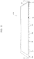
- FIG. 6 is a plan view illustrating an example of the rollable structure 140 in a completely unrolled state.
- FIG. 7 is a lateral view illustrating the rollable structure 140 in a completely rolled state.
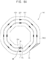
- FIG. 8A is a lateral view illustrating magnetic objects attached to a bezel region of the rollable structure 140 according to example embodiments.
- FIG. 8B is a lateral view illustrating magnetic objects attached to a bezel region of the rollable structure 140 according to other example embodiments.
- the rollable structure 140 may include the plurality of unit structures CR1 through CRi.
- the rollable structure 140 may be rolled or unrolled based on the unit structures CR1 through CRi.
- respective widths of the unit structures CR1 through CRi may increase in a direction from a first side FS of the rollable structure 140 to a second side SS of the rollable structure 140, where the first side FS of the rollable structure 140 is opposite to the second side SS of the rollable structure 140.
- the display panel structure 120 may be attached to the rollable structure 140, as illustrated in FIG. 5 .
- the peripheral region of the display panel structure i.e., the hatched area in FIG. 6 surrounding a region of a display panel structure
- the magnetic objects IB and OB may be attached to the bezel region BZ of the rollable structure 140.
- a first width of each of the magnetic objects IB and OB may be smaller than a width of a respective unit structure in the first direction FDN
- a second width of each of the magnetic objects IB and OB may be equal to or smaller than a width of the bezel region BZ in a direction crossing the first direction FDN.
- the magnetic objects IB and OB may be attached to an upper surface and/or a lower surface of the bezel region BZ of the unit structures CR1 through CRi included in the rollable structure 140. For example, as illustrated in FIG.
- the unit structures CR1 through CRi may collectively form the first through third rolling cycles FCY, SCY, and TCY as the rollable structure 140 is rolled.
- the second rolling cycle SCY may encircle the first rolling cycle FCY
- the third rolling cycle TCY may encircle the second rolling cycle SCY.
- the magnetic objects IB and OB attached to the bezel region BZ of the rollable structure 140 may align the first rolling cycle FCY with the second rolling cycle SCY by causing a magnetic attraction between the first rolling cycle FCY and the second rolling cycle SCY, and may align the second rolling cycle SCY with the third rolling cycle TCY by causing a magnetic attraction between the second rolling cycle SCY and the third rolling cycle TCY.
- the magnetic objects IB and OB attached to the bezel region BZ of the rollable structure 140 may secure a sufficient space between the first rolling cycle FCY and the second rolling cycle SCY, and may secure a sufficient space between the second rolling cycle SCY and the third rolling cycle TCY.
- the magnetic objects IB and OB attached to the bezel region BZ of the rollable structure 140 may prevent the display panel structure attached to the rollable structure 140 from being damaged or deteriorated by performing alignments between the first through third rolling cycles FCY, SCY, and TCY to prevent a collision between the first through third rolling cycles FCY, SCY, and TCY.
- the magnetic objects IB and OB attached to the bezel region BZ of the rollable structure 140 may be permanent magnets. In this case, the magnetic objects IB and OB attached to the bezel region BZ of the rollable structure 140 may maintain a magnetic force. In another example embodiment, the magnetic objects IB and OB attached to the bezel region BZ of the rollable structure 140 may be electromagnets. In this case, the magnetic objects IB and OB attached to the bezel region BZ of the rollable structure 140 may have the magnetic force when a current flows through the magnetic objects IB and OB. That is, the magnetic objects IB and OB attached to the bezel region BZ of the rollable structure 140 may lose the magnetic force when no current flows through the magnetic objects IB and OB. Hence, when the magnetic objects IB and OB attached to the bezel region BZ of the rollable structure 140 are implemented by the electromagnets, a user may control the magnetic objects IB and OB to have the magnetic force when needed.
- the magnetic objects IB and OB attached to the bezel region BZ of the rollable structure 400 may be attached to all of the unit structures CR1 through CRi included in the rollable structure 400. That is, at least one of the magnetic objects IB and OB attached to the bezel region BZ of the rollable structure 400 may be attached to each of the unit structures CR1 through CRi included in the rollable structure 400.
- the first rolling cycle FCY may include first through eighth unit structures CR
- the second rolling cycle SCY may include ninth through sixteenth unit structures CR
- the third rolling cycle TCY may include the seventeenth through twenty-third unit structures CR.
- the magnetic objects IB and OB attached to the bezel region BZ of the rollable structure 400 may be attached to each one of the first through twenty-third unit structures CR1 through CR23 ( FIG. 8A ).
- the magnetic objects IB and OB attached to the bezel region BZ of the rollable structure 140 may be attached to, e.g., only, some of the unit structures CR included in the rollable structure 140.
- the first rolling cycle FCY may include the first through eighth unit structures CR
- the second rolling cycle SCY may include the ninth through sixteenth unit structures CR
- the third rolling cycle TCY may include the seventeenth through twenty-third unit structures CR.
- the magnetic objects IB and OB attached to the bezel region BZ of the rollable structure 140 may be attached to only the odd numbered unit structures CR, i.e., to the first unit structure CR, the third unit structure CR, the fifth unit structure CR, the seventh unit structure CR, the ninth unit structure CR, the eleventh unit structure CR, the thirteenth unit structure CR, the fifteenth unit structure CR, the seventeenth unit structure CR, the nineteenth unit structure CR, the twenty-first unit structure CR, and the twenty-third unit structure CR.
- target unit structures to which the magnetic objects IB and OB are attached may be selected in various ways. Although the magnetic objects IB and OB are mentioned above, in some example embodiments, one of the magnetic objects IB and OB may be replaced with metal objects.
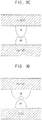
- FIGS. 9A through 9E are diagrams illustrating various shapes of the magnetic objects OB and IB in the rollable structure 140. It is noted that each of FIGS. 9A through 9E is an enlarged view of portion P in FIG. 8A .
- a first surface of the (k)th rolling cycle (k)CY may face a second surface of the (k-1)th rolling cycle (k-1)CY.
- the (k)th rolling cycle (k)CY may be aligned with the (k-1)th rolling cycle (k-1)CY by magnetic attachment of the magnetic objects OB and IB due to the magnetic force (i.e., the magnetic attraction) between the magnetic object OB attached to the first surface of the (k)th rolling cycle (k)CY and the magnetic object IB attached to the second surface of the (k-1)th rolling cycle (k-1)CY.
- the magnetic object OB attached to the first surface of the (k)th rolling cycle (k)CY and the magnetic object IB attached to the second surface of the (k-1)th rolling cycle (k-1)CY may be magnetic objects.
- a first polarity (e.g., north pole N or south pole S) of the first magnetic object OB attached to the first surface of the (k)th rolling cycle may be exposed
- a second polarity (e.g., south pole S or north pole N) of the second magnetic object IB attached to the second surface of the (k-1)th rolling cycle may be exposed.
- a shape of the first magnetic object OB attached to the first surface of the (k)th rolling cycle (k)CY and a shape of the second magnetic object IB attached to the second surface of the (k-1)th rolling cycle (k-1)CY may be variously determined.
- the first magnetic object OB attached to the first surface of the (k)th rolling cycle (k)CY may have a first thickness (or, height), and the second magnetic object IB attached to the second surface of the (k-1)th rolling cycle (k-1)CY may have a second thickness.
- a width of a space between the (k)th rolling cycle (k)CY and the (k-1)th rolling cycle (k-1)CY may equal a sum of the first thickness and the second thickness.
- the space between the (k)th rolling cycle (k)CY and the (k-1)th rolling cycle (k-1)CY may be maintained constant, i.e., a sum of the first and second thicknesses, and collision between the (k)th rolling cycle (k)CY and the (k-1)th rolling cycle (k-1)CY may be prevented, e.g., due to sufficient space secured between the (k)th rolling cycle (k)CY and the (k-1)th rolling cycle (k-1)CY.
- the shapes of the first magnetic objects OB may be identical to those of the second magnetic objects IB, e.g., curved ( FIG. 9A ) or rectangular ( FIG. 9B ).
- the shapes of the first magnetic objects OB may be complementary with respect to those of the second magnetic objects IB, so a total sum of the first and second thicknesses may still define the width of the space between the (k)th rolling cycle (k)CY and the (k-1)th rolling cycle (k-1)CY.
- the shapes of the first magnetic objects OB may be symmetric with respect to a diagonal line extending between the (k)th rolling cycle (k)CY and the (k-1)th rolling cycle (k-1)CY.
- the magnetic object IB attached to the second surface of the (k-1)th rolling cycle (k-1)CY may be a magnetic object
- the magnetic object OB attached to the first surface of the (k)th rolling cycle (k)CY may be a metal object that can stick to the magnetic object.
- the magnetic object IB may be attached to the second surface of the (k-1)th rolling cycle (k-1)CY
- the metal object OB may be attached to the first surface of the (k)th rolling cycle (k)CY.
- magnetic attraction may be caused between the metal object OB attached to the first surface of the (k)th rolling cycle (k)CY and the magnetic object IB attached to the second surface of the (k-1)th rolling cycle (k-1)CY.
- a shape of the metal object OB attached to the first surface of the (k)th rolling cycle (k)CY and a shape of the magnetic object IB attached to the second surface of the (k-1)th rolling cycle (k-1)CY may be variously determined.
- the metal object OB attached to the first surface of the (k)th rolling cycle (k)CY may have a first thickness (or, height), and the magnetic object IB attached to the second surface of the (k-1)th rolling cycle (k-1)CY may have a second thickness.
- a space corresponding to a value generated by summing the first thickness and the second thickness may be secured between the (k)th rolling cycle (k)CY and the (k-1)th rolling cycle (k-1)CY.
- the collision between the (k)th rolling cycle (k)CY and the (k-1)th rolling cycle (k-1)CY may be prevented because a sufficient space is secured between the (k)th rolling cycle (k)CY and the (k-1)th rolling cycle (k-1)CY.
- various shapes of the aligners OB and IB are illustrated in FIGS. 9A through 9E , the shapes of the aligners OB and IB are not limited thereto. According to requirements for designing the rollable display device, the shapes of the aligners OB and IB may be variously determined.
- FIG. 10 is a block diagram illustrating an electronic device according to example embodiments.
- an electronic device 700 may include a processor 710, a memory device 720, a storage device 730, an input/output (I/O) device 740, a rolling detection sensor 750, and a rollable display device 760.
- the rollable display device 760 may be the rollable display device 100 of FIG. 1 .
- the rollable display device 760 may be implemented by an organic light emitting display (OLED) device, a liquid crystal display (LCD) device, etc.
- the electronic device 700 may further include a plurality of ports for communicating with a video card, a sound card, a memory card, a universal serial bus (USB) device, other electronic devices, etc.
- the electronic device 700 may be implemented as a cellular phone, a smart phone, a video phone, a smart pad, a smart watch, a tablet PC, a car navigation system, a television, a computer monitor, a laptop, a head mounted display (HMD) device, etc.
- a cellular phone a smart phone, a video phone, a smart pad, a smart watch, a tablet PC, a car navigation system, a television, a computer monitor, a laptop, a head mounted display (HMD) device, etc.
- HMD head mounted display
- the processor 710 may perform various computing functions.
- the processor 710 may control a displaying operation of the rollable display device 760 based on a rolling detection signal indicating whether the rollable display device 760 is rolled or unrolled when the rolling detection sensor 750 outputs the rolling detection signal.
- the processor 710 may be a micro processor, a central processing unit (CPU), an application processor (AP), etc.
- the processor 710 may be coupled to other components via an address bus, a control bus, a data bus, etc. Further, the processor 710 may be coupled to an extended bus such as a peripheral component interconnection (PCI) bus.
- PCI peripheral component interconnection
- the memory device 720 may store data for operations of the electronic device 700.
- the memory device 720 may include at least one non-volatile memory device such as an erasable programmable read-only memory (EPROM) device, an electrically erasable programmable read-only memory (EEPROM) device, a flash memory device, a phase change random access memory (PRAM) device, a resistance random access memory (RRAM) device, a nano floating gate memory (NFGM) device, a polymer random access memory (PoRAM) device, a magnetic random access memory (MRAM) device, a ferroelectric random access memory (FRAM) device, etc., and/or at least one volatile memory device such as a dynamic random access memory (DRAM) device, a static random access memory (SRAM) device, a mobile DRAM device, etc.
- DRAM dynamic random access memory
- SRAM static random access memory
- the storage device 730 may include a solid state drive (SSD) device, a hard disk drive (HDD) device, a CD-ROM device, etc.
- the I/O device 740 may include an input device such as a keyboard, a keypad, a mouse device, a touchpad, a touch-screen, etc. and an output device such as a printer, a speaker, etc.
- the electronic device 700 may further include a power supply that provides power for operations of the electronic device 700.
- the rolling detection sensor 750 may generate the rolling detection signal indicating whether the rollable display device 760 is rolled or unrolled and may provide the rolling detection signal to the processor 710.
- the rollable display device 760 may selectively perform a displaying operation suitable for a rolled state of the rollable display device 760 and a displaying operation suitable for an unrolled state of the rollable display device 760.
- the rollable display device 760 may be coupled to other components via the buses or other communication links. In some example embodiments, the rollable display device 760 may be included in the I/O device 740.
- the rollable display device 760 may include a display panel structure and a rollable structure to which the display panel structure is attached.
- the rollable structure may include a plurality of unit structures of which respective widths increase in a direction from a first side of the rollable structure to a second side of the rollable structure that is opposite to the first side of the rollable structure.
- the rollable structure may be rolled or unrolled based on the unit structures.
- the rollable display device 760 may secure a sufficient space between rolling cycles, where the unit structures collectively form the rolling cycles as the rollable structure is rolled, when the rollable structure is rolled based on the unit structures included in the rollable structure.
- the rollable display device 760 may prevent the display panel structure attached to the rollable structure from being damaged or deteriorated by a collision between the rolling cycles.
- magnetic objects for securing the space between adjacent rolling cycles by causing a magnetic attraction between the adjacent rolling cycles may be attached to a bezel region of the rollable structure included in the rollable display device 760.
- the magnetic objects may be permanent magnets or electromagnets.
- the magnetic objects are not limited thereto.
- the magnetic objects may be attached to all unit structures included in the rollable structure.
- the magnetic objects may be attached to some of the unit structures included in the rollable structure. Since the rollable display device 760 is described above, duplicated descriptions will not be repeated.
- Example embodiments may be applied to a rollable display device and an electronic device including the rollable display device.
- the rollable display device may include a rolltop display device, a bendable display device, a flexible display device, etc.
- the electronic device may include a mobile device, e.g., a smart phone, a smart pad, a smart watch, a cellular phone, a video phone, a tablet PC, a car navigation system, a television, a computer monitor, a laptop, a head mounted display device, etc.
- example embodiments provide a rollable display device capable of preventing a display panel structure attached to a rollable structure from being damaged (e.g., scratch, crack, etc.) or deteriorated by a collision between rolling cycles by securing a sufficient space between the rolling cycles when the rollable structure is rolled.
- Example embodiments also provide an electronic device including the rollable display device (e.g., a flexible electronic device, a rollable electronic device, etc.).
- a rollable display device may include a display panel structure and a rollable structure to which the display panel structure is attached, may increase respective widths of unit structures included in the rollable structure in a direction from a first side of the rollable structure to a second side of the rollable structure that is opposite to the first side of the rollable structure, and may align rolling cycles, where the unit structures collectively form the rolling cycles as the rollable structure is rolled, using magnetic objects attached to a bezel region of the rollable structure when the rollable structure is rolled based on the unit structures included in the rollable structure.
- the rollable display device may prevent the display panel structure attached to the rollable structure from being damaged (e.g., scratch, crack, etc.) or deteriorated by a collision between the rolling cycles by securing a sufficient space between the rolling cycles when the rollable structure is rolled.
- an electronic device including the rollable display device may achieve durability by preventing (or, minimizing) damage or deterioration of the display panel structure included in the rollable display device while achieving portability, usability, and good design.
Landscapes
- Engineering & Computer Science (AREA)
- Theoretical Computer Science (AREA)
- Physics & Mathematics (AREA)
- General Physics & Mathematics (AREA)
- General Engineering & Computer Science (AREA)
- Computer Hardware Design (AREA)
- Human Computer Interaction (AREA)
- Quality & Reliability (AREA)
- Computing Systems (AREA)
- Nonlinear Science (AREA)
- Microelectronics & Electronic Packaging (AREA)
- Mathematical Physics (AREA)
- Chemical & Material Sciences (AREA)
- Crystallography & Structural Chemistry (AREA)
- Optics & Photonics (AREA)
- Devices For Indicating Variable Information By Combining Individual Elements (AREA)
Description
- The present invention relates to an electronic device. More particularly, embodiments relate to a rollable display device that can be rolled and unrolled by a user and an electronic device including the rollable display device.
- Recently, consumers attribute greater importance to design of an electronic device when purchasing the electronic device. Further, consumers want an electronic device that can provide a user (e.g., a viewer) with a relatively large image while having portability. Accordingly, a rollable display device is spotlighted as a display device that is included in an electronic device.
- Generally, a rollable display device is rolled to achieve a relatively small size when carried, and is unrolled to provide relatively large images to a user when used. To this end, the rollable display device includes a rollable structure and a display panel structure that is attached to the rollable structure. Here, the display panel structure is rolled when the rollable structure is rolled by the user, while the display panel structure is unrolled when the rollable structure is unrolled by the user. In the rollable display device, a plurality of rolling cycles is formed as the rollable structure is rolled.
- According to an embodiment of the present invention, a rollable display device is provided that includes a rollable structure including a plurality of unit structures, the rollable structure being configured to be rolled and unrolled based on the unit structures, and a display panel structure attached to the rollable structure. Here, respective widths of the unit structures may increase in a direction from a first side of the rollable structure to a second side of the rollable structure, the first side of the rollable structure being opposite to the second side of the rollable structure. In addition, the unit structures collectively form (i.e., constitute) first through (n)th rolling cycles, where n is an integer grater than or equal to 2, as the rollable structure is rolled, and a (k)th rolling cycle may encircle a (k-1)th rolling cycle, where k is an integer between 2 and n. Further, a plurality of magnetic objects that aligns the (k)th rolling cycle with the (k-1)th rolling cycle by causing a magnetic attraction between the (k)th rolling cycle and the (k-1)th rolling cycle are attached to a bezel region of the rollable structure.
- In a preferred embodiment, a first surface of the (k)th rolling cycle faces a second surface of the (k-1)th rolling cycle, a first polarity of first magnetic objects attached to the first surface of the (k)th rolling cycle is exposed, and a second polarity of second magnetic objects attached to the second surface of the (k-1)th rolling cycle is exposed, the first polarity being opposite to the second polarity.
- In a further preferred embodiment, the first magnetic objects have a first thickness, the second magnetic objects have a second thickness, and a space corresponding to a value generated by summing the first thickness and the second thickness may be secured between the (k)th rolling cycle and the (k-1)th rolling cycle.
- In a further preferred embodiment, a first surface of the (k)th rolling cycle faces a second surface of the (k-1)th rolling cycle, the magnetic objects are attached to the second surface of the (k-1)th rolling cycle, and metal objects are attached to the first surface of the (k)th rolling cycle, wherein the metal objects are able to stick to the magnetic objects.
- In a further preferred embodiment, the magnetic objects have a first thickness, the metal objects have a second thickness, and a space corresponding to a value generated by summing the first thickness and the second thickness is secured between the (k)th rolling cycle and the (k-1)th rolling cycle.
- In a further preferred embodiment, the magnetic objects are permanent magnets.
- In a further preferred embodiment, the magnetic objects are electromagnets.
- In a further preferred embodiment, the magnetic objects are attached to all of the unit structures included in the rollable structure.
- In a further preferred embodiment, the magnetic objects are attached to some of the unit structures included in the rollable structure.
- In a further preferred embodiment, an angle between adjacent ones of the unit structures is maintained to be greater than or equal to a reference angle in each of the first through (n)th rolling cycles.
- In a further preferred embodiment, the rollable structure further includes a circuit structure that is adjacent to the second side of the rollable structure, a driving integrated circuit that is configured to drive the display panel structure is located within the circuit structure, and a thickness of the circuit structure is thinner than respective thicknesses of the unit structures.
- According to another aspect of the present invention, an electronic device is provided that includes a rollable display device, a rolling detection sensor configured to generate a rolling detection signal indicating whether the rollable display device is rolled or unrolled, and a processor configured to control a displaying operation of the rollable display device based on the rolling detection signal. The rollable display device includes a rollable structure including a plurality of unit structures, the rollable structure being configured to be rolled and unrolled based on the unit structures, and a display panel structure attached to the rollable structure. Here, respective widths of the unit structures increase in a direction from a first side of the rollable structure to a second side of the rollable structure, the first side of the rollable structure being opposite to the second side of the rollable structure. In addition, the unit structures collectively form first through (n)th rolling cycles, where n is an integer grater than or equal to 2, as the rollable structure is rolled, and a (k)th rolling cycle encircles a (k-1)th rolling cycle, where k is an integer between 2 and n. Further, a plurality of magnetic objects that aligns the (k)th rolling cycle with the (k-1)th rolling cycle by causing a magnetic attraction between the (k)th rolling cycle and the (k-1)th rolling cycle is attached to a bezel region of the rollable structure.
- In a preferred embodiment, a first surface of the (k)th rolling cycle faces a second surface of the (k-1)th rolling cycle, a first polarity of first magnetic objects attached to the first surface of the (k)th rolling cycle is exposed, and a second polarity of second magnetic objects attached to the second surface of the (k-1)th rolling cycle is exposed, the first polarity being opposite to the second polarity.
- In a further preferred embodiment, the first magnetic objects have a first thickness, the second magnetic objects have a second thickness, and a space corresponding to a value generated by summing the first thickness and the second thickness is secured between the (k)th rolling cycle and the (k-1)th rolling cycle.
- In a further preferred embodiment, a first surface of the (k)th rolling cycle faces a second surface of the (k-1)th rolling cycle, the magnetic objects are attached to the second surface of the (k-1)th rolling cycle, and metal objects are attached to the first surface of the (k)th rolling cycle, wherein the metal objects are able to stick to the magnetic objects.
- In a further preferred embodiment, the magnetic objects have a first thickness, the metal objects have a second thickness, and a space corresponding to a value generated by summing the first thickness and the second thickness is secured between the (k)th rolling cycle and the (k-1)th rolling cycle.
- In a further preferred embodiment, the magnetic objects are permanent magnets.
- In a further preferred embodiment, the magnetic objects are electromagnets.
- In a further preferred embodiment, the magnetic objects are attached to all of the unit structures included in the rollable structure.
- In a further preferred embodiment, the magnetic objects is attached to some of the unit structures included in the rollable structure.
- Features will become apparent to those of ordinary skill in the art by describing in detail exemplary embodiments with reference to the attached drawings in which:
-
FIG. 1 illustrates a diagram of a rollable display device according to example embodiments. -
FIG. 2 illustrates a plan view of a rollable structure included in the rollable display device ofFIG. 1 . -
FIG. 3 illustrates a block diagram of a displaying operation of the rollable display device ofFIG. 1 . -
FIG. 4 illustrates a diagram of an example in which the rollable display device ofFIG. 1 is completely rolled. -
FIG. 5 illustrates a diagram of an example in which the rollable display device ofFIG. 1 is completely unrolled. -
FIG. 6 illustrates a plan view of an example in which a rollable structure included in the rollable display device ofFIG. 1 is completely unrolled. -
FIG. 7 illustrates a lateral view of an example in which a rollable structure included in the rollable display device ofFIG. 1 is completely rolled. -
FIG. 8A illustrates a lateral view of an example in which magnetic objects are attached to a bezel region of a rollable structure included in the rollable display device ofFIG. 1 . -
FIG. 8B illustrates a lateral view of another example in which magnetic objects are attached to a bezel region of a rollable structure included in the rollable display device ofFIG. 1 . -
FIGS. 9A through 9E illustrate diagrams of various shapes of magnetic objects that are attached to a bezel region of a rollable structure included in the rollable display device ofFIG. 1 . -
FIG. 10 illustrates a block diagram of an electronic device according to example embodiments. - Example embodiments will now be described more fully hereinafter with reference to the accompanying drawings; however, they may be embodied in different forms and should not be construed as limited to the embodiments set forth herein. Rather, these embodiments are provided so that this disclosure will be thorough and complete, and will fully convey exemplary implementations to those skilled in the art.
- In the drawing figures, the dimensions of layers and regions may be exaggerated for clarity of illustration. It will also be understood that when a layer or element is referred to as being "on" another layer or substrate, it can be directly on the other layer or substrate, or intervening layers may also be present. In addition, it will also be understood that when a layer is referred to as being "between" two layers, it can be the only layer between the two layers, or one or more intervening layers may also be present. Like reference numerals refer to like elements throughout.
- Hereinafter, embodiments will be explained in detail with reference to the accompanying drawings.
-
FIG. 1 is a diagram illustrating a rollable display device according to example embodiments.FIG. 2 is a plan view illustrating a rollable structure included in the rollable display device ofFIG. 1 .FIG. 3 is a block diagram for describing a displaying operation of the rollable display device ofFIG. 1 . - Referring to
FIGS. 1 through 3 , therollable display device 100 may include adisplay panel structure 120 and arollable structure 140. In an example embodiment, therollable display device 100 may further include a drivingintegrated circuit 180 that drives thedisplay panel structure 120. As illustrated inFIG. 3 , thedisplay panel structure 120 and therollable structure 140 may constitute adisplay panel 160. - In an example embodiment, the
rollable structure 140 may further include a circuit structure NCR that is adjacent to a second side SS of therollable structure 140, and the drivingintegrated circuit 180 may be located in the circuit structure NCR of therollable structure 140. In some example embodiments, the drivingintegrated circuit 180 may be located outside therollable display device 100, and thus the circuit structure NCR may be omitted from therollable structure 140. In an example embodiment, therollable structure 140 may further include a dummy structure that is adjacent to a first side FS of therollable structure 140. The dummy structure of therollable structure 140 may be prepared to provide a region of therollable display device 100 that a user can grab (i.e., for user convenience) or to protect therollable display device 100 from external shocks. Thus, thedisplay panel structure 120 may not be located on the dummy structure of therollable structure 140. In some example embodiments, when therollable structure 140 does not include the circuit structure NCR, therollable structure 140 may further include the dummy structure instead of the circuit structure NCR. - The
display panel structure 120 may be attached to therollable structure 140. Here, since thedisplay panel structure 120 is manufactured with flexible materials, thedisplay panel structure 120 may be rolled and unrolled as therollable structure 140 is rolled and unrolled. Thedisplay panel structure 120 may include a plurality of pixels. In an example embodiment, the pixels may include red color emission pixels, green color emission pixels, and blue color emission pixels. In another example embodiment, the pixels may include red color emission pixels, green color emission pixels, blue color emission pixels, and white color emission pixels. Thus, thedisplay panel structure 120 may display an image using the pixels. - In an example embodiment, the
rollable display device 100 may be an organic light emitting diode (OLED) display device. In this case, thedisplay panel structure 120 may include an organic light emitting structure including organic light emitting diodes. In another example embodiment, therollable display device 100 may be a liquid crystal display (LCD) device. In this case, thedisplay panel structure 120 may include a liquid crystal structure including liquid crystals. However, therollable display device 100 is not limited thereto. - The
rollable structure 140 may include a plurality of unit structures CR1 through CRi, and thus therollable structure 140 may be rolled and unrolled based on the unit structures CR1 through CRi (e.g., the shape, structure, and configuration of therollable structure 140, when rolled, may be determined by the shapes, sizes, and configurations of the unit structures CR1 through CRi). Here, respective widths W1 through Wi of the unit structures CR1 through CRi may incrementally increase in a direction from the first side FS of therollable structure 140 to the second side SS of therollable structure 140, the second side SS of therollable structure 140 being opposite to the first side FS of therollable structure 140. - For example, the width W2 of the second unit structure CR2 may be greater than the width W1 of the first unit structure CR1 that is closest to the first side FS of the
rollable structure 140, the width W3 of the third unit structure CR3 may be greater than the width W2 of the second unit structure CR2, and the width W4 of the fourth unit structure CR4 may be greater than the width W3 of the third unit structure CR3. Thus, thedisplay panel structure 120 may not be damaged or separated from therollable structure 140 when therollable structure 140 is rolled in a first direction FDN. In example embodiments, an angle between adjacent ones of the unit structures CR1 through CRi may be maintained to be greater than or equal to a reference angle. - As the
rollable structure 140, to which thedisplay panel structure 120 is attached, is rolled, the unit structures CR1 through CRi may collectively form first through (n)th rolling cycles, where n is an integer greater than or equal to 2. Here, the (k)th rolling cycle may encircle the (k-1)th rolling cycle, where k is an integer between 2 and n. That is, the unit structures CR1 through CRi may sequentially constitute the first through (n)th rolling cycles as therollable structure 140, to which thedisplay panel structure 120 is attached, is rolled. - If a sufficient space between the first through (n)th rolling cycles is not secured, the
display panel structure 120 attached to therollable structure 140 may be damaged (e.g., scratch, crack, etc.) or deteriorated (e.g., deterioration due to misalignment) by a collision between the first through (n)th rolling cycles. For example, because the unit structures CR1 through CRi sequentially constitute the first through fourth rolling cycles as therollable structure 140 is rolled in the first direction FDN, the second rolling cycle may encircle the first rolling cycle, the third rolling cycle may encircle the second rolling cycle, and the fourth rolling cycle may encircle the third rolling cycle. However, if insufficient space is provided between adjacent rolling cycles of first through (n)th rolling cycles, the first rolling cycle may collide with the second rolling cycle that encircles the first rolling cycle, the second rolling cycle may collide with the third rolling cycle that encircles the second rolling cycle, and the third rolling cycle may collide with the fourth rolling cycle that encircles the third rolling cycle. - Therefore, according to example embodiments, magnetic objects, e.g., aligners, for securing a sufficient space between the (k)th rolling cycle and the (k-1)th rolling cycle may be attached to a bezel region of the
rollable structure 140, where the magnetic objects align the (k)th rolling cycle with the (k-1)th rolling cycle by generating a magnetic attraction between the (k)th rolling cycle and the (k-1)th rolling cycle. For example, the magnetic objects may be permanent magnets that maintain magnetic force constantly. - In another example, the magnetic objects may be electromagnets, i.e., the magnetic objects may exhibit magnetic force when a current flows through the magnetic objects. That is, the magnetic objects (i.e., the electromagnets) may lose the magnetic force when no current flows through the magnetic objects. Therefore, when the magnetic objects attached to the bezel region of the
rollable structure 140 are implemented by the electromagnets, a user may control the magnetic objects to have the magnetic force when needed. For example, when the user unrolls therollable display device 100 to use therollable display device 100, the user may control the magnetic objects not to have the magnetic force. On the other hand, when the user rolls therollable display device 100 to carry therollable display device 100, the user may control the magnetic objects to have the magnetic force. - In an example embodiment, when a first surface of the (k)th rolling cycle faces a second surface of the (k-1)th rolling cycle, a first polarity (e.g., north pole N or south pole S) of first magnetic objects attached to the first surface of the (k)th rolling cycle may be exposed, and a second polarity (e.g., south pole S or north pole N), which is opposite to the first polarity, of second magnetic objects attached to the second surface of the (k-1)th rolling cycle may be exposed. Thus, as the
rollable structure 140, to which thedisplay panel structure 120 is attached, is rolled, magnetic force (i.e., magnetic attraction) may be caused between the first magnetic objects attached to the first surface of the (k)th rolling cycle and the second magnetic objects attached to the second surface of the (k-1)th rolling cycle, and thus the (k)th rolling cycle may be aligned with the (k-1)th rolling cycle by magnetic attachment of the first magnetic objects and the second magnetic objects. - In addition, when the first magnetic objects attached to the first surface of the (k)th rolling cycle have a first thickness and the second magnetic objects attached to the second surface of the (k-1)th rolling cycle have a second thickness, a space corresponding to a value generated by summing the first thickness and the second thickness may be secured between the (k)th rolling cycle and the (k-1)th rolling cycle. That is, because a sufficient space is secured between the (k)th rolling cycle and the (k-1)th rolling cycle, collision between the (k)th rolling cycle and the (k-1)th rolling cycle may be prevented.
- In another example embodiment, when the first surface of the (k)th rolling cycle faces the second surface of the (k-1)th rolling cycle, magnetic objects may be attached to the second surface of the (k-1)th rolling cycle, and metal objects may be attached to the first surface of the (k)th rolling cycle, i.e., the metal objects may include metal that can stick to the magnetic objects. Thus, as the
rollable structure 140, to which thedisplay panel structure 120 is attached, is rolled, magnetic force (i.e., magnetic attraction) may be caused between the metal objects attached to the first surface of the (k)th rolling cycle and the magnetic objects attached to the second surface of the (k-1)th rolling cycle, and thus the (k)th rolling cycle may be aligned with the (k-1)th rolling cycle by magnetic attachment of the magnetic objects and the metal objects. - In addition, when the magnetic objects attached to the second surface of the (k-1)th rolling cycle have a first thickness and the metal objects attached to the first surface of the (k)th rolling cycle have a second thickness, a space corresponding to a value generated by summing the first thickness and the second thickness may be secured between the (k)th rolling cycle and the (k-1)th rolling cycle. That is, because a sufficient space is secured between the (k)th rolling cycle and the (k-1)th rolling cycle, collision between the (k)th rolling cycle and the (k-1)th rolling cycle may be prevented.
- In an example embodiment, the magnetic objects attached to the bezel region of the
rollable structure 140 may be attached to all unit structures CR1 through CRi included in therollable structure 140. That is, at least one magnetic object may be attached to each of the unit structures CR1 through CRi included in therollable structure 140. In another example embodiment, the magnetic objects attached to the bezel region of therollable structure 140 may be attached to some of the unit structures CR1 through CRi included in therollable structure 140. - As described above, the
rollable structure 140 may include the circuit structure NCR that is adjacent to the second side SS of therollable structure 140. In this case, a chip-on flexible (COF) printed circuit board, a flexible printed circuit board (FPCB), a power connector, etc., as well as the drivingintegrated circuit 180, may be included in the circuit structure NCR of therollable structure 140. In an example embodiment, as illustrated inFIG. 1 , a thickness of the circuit structure NCR of therollable structure 140 may be thinner than respective thicknesses of the unit structures CR1 through CRi of therollable structure 140. As illustrated inFIG. 3 , the drivingintegrated circuit 180 may drive thedisplay panel 160, which thedisplay panel structure 120 and therollable structure 140 constitute. For this operation, the drivingintegrated circuit 180 may include a scan driver, a data driver, a timing controller, etc. Thedisplay panel 160 may be connected to the drivingintegrated circuit 180 via scan-lines and data-lines. The scan driver may provide a scan signal to thedisplay panel 160 via the scan-lines. The data driver may provide a data signal to thedisplay panel 160 via the data-lines. The timing controller may control the scan driver, the data driver, etc. However, components included in the drivingintegrated circuit 180 are not limited thereto. For example, the drivingintegrated circuit 180 may further include a power supply that supplies power to thedisplay panel 160. - As discussed previously, the
rollable display device 100 may include thedisplay panel structure 120 and therollable structure 140. Here, therollable display device 100 may include, e.g., gradually, increased respective widths W1 through Wi of the unit structures CR1 through CRi in the first direction FDN, i.e., a direction from the first side FS of therollable structure 140 to the second side SS of therollable structure 140. Thus, therollable display device 100 may prevent a stress from being applied to thedisplay panel structure 120 when therollable structure 140 is rolled and unrolled by the user, and thus may prevent thedisplay panel structure 120 from being damaged or separated from therollable structure 140. That is, in therollable display device 100, since respective widths W1 through Wi of the unit structures CR1 through CRi increase in the direction from the first side FS of therollable structure 140 to the second side SS of therollable structure 140, a stress accumulated from an inner rolling cycle to an outer rolling cycle may be alleviated, and thus a severe stress may not be applied to thedisplay panel structure 120. - In addition, the
rollable display device 100 may prevent thedisplay panel structure 120 attached to therollable structure 140 from being damaged or deteriorated by collision between the rolling cycles, where the unit structures CR1 through CRi collectively form the rolling cycles as therollable structure 140 is rolled, by aligning the rolling cycles using magnetic objects attached to the bezel region of therollable structure 140 when therollable structure 140 is rolled based on the unit structures CR1 through CRi included in therollable structure 140 to secure sufficient space between the rolling cycles when therollable structure 140 is rolled based on the unit structures CR1 through CRi included in therollable structure 140. In example embodiments, since magnetic force (i.e., magnetic attraction) is caused between the rolling cycles when therollable display device 100 is completely rolled, a rolled state of therollable display device 100 may be maintained until the user unrolls therollable display device 100. -
FIG. 4 is a schematic diagram illustrating an example in which therollable display device 100 is completely rolled.FIG. 5 is a perspective view of therollable display device 100 when it is completely unrolled. - In detail, referring to
FIGS. 4 and5 , the rollable display device may include therollable structure 140 and thedisplay panel structure 120. Thedisplay panel structure 120 may be attached to therollable structure 140. Therollable structure 140 may include the plurality of unit structures CR. Therollable structure 140 may be rolled or unrolled based on the unit structures CR. - As illustrated in
FIG. 5 , respective widths of the unit structures CR may increase in a direction from the first side FS of therollable structure 140 to the second side SS of therollable structure 140, where the second side SS of therollable structure 140 is opposite to the first side FS of therollable structure 140. For example, as further illustrated inFIG. 5 , when the unit structures CR of therollable structure 140 are unrolled to define a flat upper surface, thedisplay panel structure 120 may be unrolled on the defined flat surface to display an image. Therollable structure 140 may further include the circuit structure NCR that is adjacent to the second side SS of therollable structure 140, e.g., at a left side of thedisplay panel structure 120 inFIG. 5 . - As further illustrated in
FIG. 5 , a peripheral region of thedisplay panel structure 120 attached to the rollable structure 140 (i.e., a region surrounding the display panel structure 120) may be a bezel region BZ of therollable structure 140. For example, a peripheral portion of therollable structure 140 not overlapped by thedisplay panel structure 120 and, e.g., completely, surrounding thedisplay panel structure 120 may be the bezel region BZ. - As described above, as the
rollable structure 140 is rolled, the unit structures CR of therollable structure 140 may collectively form first through (n)th rolling cycles, with a (k)th rolling cycle may encircle a (k-1)th rolling cycle. For example, referring toFIGS. 4-5 , the unit structures CR (FIG. 5 ) may be collectively rolled to form first through third rolling cycles FCY, SCY, and TCY (FIG. 4 ), with thedisplay panel structure 120 being on a surface of therollable structure 140 facing an interior of the rolled structure. Here, the second rolling cycle SCY may encircle the first rolling cycle FCY, and the third rolling cycle TCY may encircle the second rolling cycle SCY. - Thus, in order to prevent a collision between the first through third rolling cycles FCY, SCY, and TCY, magnetic objects OB and IB may be attached to the bezel region BZ of the
rollable structure 140, as will be described in more detail with reference toFIGS. 8A-8B below. The magnetic objects may align the (k)th rolling cycle with the (k-1)th rolling cycle by causing a magnetic attraction between the (k)th rolling cycle and the (k-1)th rolling cycle. Thus, therollable structure 140 may secure a sufficient space between the (k)th rolling cycle and the (k-1)th rolling cycle. - In an example embodiment, the magnetic objects OB/IB attached to the bezel region BZ of the
rollable structure 140 may be permanent magnets. In this case, the magnetic objects attached to the bezel region BZ of therollable structure 140 may maintain a magnetic force. In another example embodiment, the magnetic objects attached to the bezel region BZ of therollable structure 140 may be electromagnets. In this case, the magnetic objects attached to the bezel region BZ of therollable structure 140 may have the magnetic force when a current flows through the magnetic objects. That is, the magnetic objects attached to the bezel region BZ of therollable structure 140 may lose the magnetic force when no current flows through the magnetic objects. - As described above, since the magnetic objects are attached to the bezel region BZ of the
rollable structure 140, therollable display device 100 may be easily rolled by the magnetic force of the magnetic objects when a user tries to roll therollable display device 100 to carry therollable display device 100. In addition, when therollable display device 100 is completely rolled, a rolled state of therollable display device 100 may be maintained by the magnetic force of the magnetic objects until the user unrolls therollable display device 100. In example embodiments, the magnetic objects attached to the bezel region BZ of therollable structure 140 may be attached to all or some of the unit structures CR included in therollable structure 140. These embodiments will be described in detail with reference toFIGS. 6 through 8B . -
FIG. 6 is a plan view illustrating an example of therollable structure 140 in a completely unrolled state.FIG. 7 is a lateral view illustrating therollable structure 140 in a completely rolled state.FIG. 8A is a lateral view illustrating magnetic objects attached to a bezel region of therollable structure 140 according to example embodiments.FIG. 8B is a lateral view illustrating magnetic objects attached to a bezel region of therollable structure 140 according to other example embodiments. - Referring to
FIGS. 6 through 8B , therollable structure 140 may include the plurality of unit structures CR1 through CRi. Therollable structure 140 may be rolled or unrolled based on the unit structures CR1 through CRi. Here, respective widths of the unit structures CR1 through CRi may increase in a direction from a first side FS of therollable structure 140 to a second side SS of therollable structure 140, where the first side FS of therollable structure 140 is opposite to the second side SS of therollable structure 140. Thedisplay panel structure 120 may be attached to therollable structure 140, as illustrated inFIG. 5 . As illustrated inFIG. 6 , the peripheral region of the display panel structure (i.e., the hatched area inFIG. 6 surrounding a region of a display panel structure) may be the bezel region BZ of therollable structure 140. - Referring to
FIG. 8A , the magnetic objects IB and OB may be attached to the bezel region BZ of therollable structure 140. For example, a first width of each of the magnetic objects IB and OB may be smaller than a width of a respective unit structure in the first direction FDN, and a second width of each of the magnetic objects IB and OB may be equal to or smaller than a width of the bezel region BZ in a direction crossing the first direction FDN. The magnetic objects IB and OB may be attached to an upper surface and/or a lower surface of the bezel region BZ of the unit structures CR1 through CRi included in therollable structure 140. For example, as illustrated inFIG. 7 , the unit structures CR1 through CRi may collectively form the first through third rolling cycles FCY, SCY, and TCY as therollable structure 140 is rolled. Here, the second rolling cycle SCY may encircle the first rolling cycle FCY, and the third rolling cycle TCY may encircle the second rolling cycle SCY. Thus, the magnetic objects IB and OB attached to the bezel region BZ of therollable structure 140 may align the first rolling cycle FCY with the second rolling cycle SCY by causing a magnetic attraction between the first rolling cycle FCY and the second rolling cycle SCY, and may align the second rolling cycle SCY with the third rolling cycle TCY by causing a magnetic attraction between the second rolling cycle SCY and the third rolling cycle TCY. - As a result, the magnetic objects IB and OB attached to the bezel region BZ of the
rollable structure 140 may secure a sufficient space between the first rolling cycle FCY and the second rolling cycle SCY, and may secure a sufficient space between the second rolling cycle SCY and the third rolling cycle TCY. In detail, the magnetic objects IB and OB attached to the bezel region BZ of therollable structure 140 may prevent the display panel structure attached to therollable structure 140 from being damaged or deteriorated by performing alignments between the first through third rolling cycles FCY, SCY, and TCY to prevent a collision between the first through third rolling cycles FCY, SCY, and TCY. - In an example embodiment, the magnetic objects IB and OB attached to the bezel region BZ of the
rollable structure 140 may be permanent magnets. In this case, the magnetic objects IB and OB attached to the bezel region BZ of therollable structure 140 may maintain a magnetic force. In another example embodiment, the magnetic objects IB and OB attached to the bezel region BZ of therollable structure 140 may be electromagnets. In this case, the magnetic objects IB and OB attached to the bezel region BZ of therollable structure 140 may have the magnetic force when a current flows through the magnetic objects IB and OB. That is, the magnetic objects IB and OB attached to the bezel region BZ of therollable structure 140 may lose the magnetic force when no current flows through the magnetic objects IB and OB. Hence, when the magnetic objects IB and OB attached to the bezel region BZ of therollable structure 140 are implemented by the electromagnets, a user may control the magnetic objects IB and OB to have the magnetic force when needed. - In an example embodiment, as illustrated in
FIG. 8A , the magnetic objects IB and OB attached to the bezel region BZ of the rollable structure 400 may be attached to all of the unit structures CR1 through CRi included in the rollable structure 400. That is, at least one of the magnetic objects IB and OB attached to the bezel region BZ of the rollable structure 400 may be attached to each of the unit structures CR1 through CRi included in the rollable structure 400. - For example, when the
rollable structure 140 includes first through twenty-third unit structures CR, the first rolling cycle FCY may include first through eighth unit structures CR, the second rolling cycle SCY may include ninth through sixteenth unit structures CR, and the third rolling cycle TCY may include the seventeenth through twenty-third unit structures CR. Here, the magnetic objects IB and OB attached to the bezel region BZ of the rollable structure 400 may be attached to each one of the first through twenty-third unit structures CR1 through CR23 (FIG. 8A ). - In another example, as illustrated in
FIG. 8B , the magnetic objects IB and OB attached to the bezel region BZ of therollable structure 140 may be attached to, e.g., only, some of the unit structures CR included in therollable structure 140. For example, when therollable structure 140 includes the first through twenty-third unit structures CR, the first rolling cycle FCY may include the first through eighth unit structures CR, the second rolling cycle SCY may include the ninth through sixteenth unit structures CR, and the third rolling cycle TCY may include the seventeenth through twenty-third unit structures CR. For example, as illustrated inFIG. 8B , the magnetic objects IB and OB attached to the bezel region BZ of therollable structure 140 may be attached to only the odd numbered unit structures CR, i.e., to the first unit structure CR, the third unit structure CR, the fifth unit structure CR, the seventh unit structure CR, the ninth unit structure CR, the eleventh unit structure CR, the thirteenth unit structure CR, the fifteenth unit structure CR, the seventeenth unit structure CR, the nineteenth unit structure CR, the twenty-first unit structure CR, and the twenty-third unit structure CR. However, target unit structures to which the magnetic objects IB and OB are attached may be selected in various ways. Although the magnetic objects IB and OB are mentioned above, in some example embodiments, one of the magnetic objects IB and OB may be replaced with metal objects. -
FIGS. 9A through 9E are diagrams illustrating various shapes of the magnetic objects OB and IB in therollable structure 140. It is noted that each ofFIGS. 9A through 9E is an enlarged view of portion P inFIG. 8A . - Referring to
FIGS. 9A through 9E , when therollable structure 140 is in a rolled state, a first surface of the (k)th rolling cycle (k)CY may face a second surface of the (k-1)th rolling cycle (k-1)CY. Here, the (k)th rolling cycle (k)CY may be aligned with the (k-1)th rolling cycle (k-1)CY by magnetic attachment of the magnetic objects OB and IB due to the magnetic force (i.e., the magnetic attraction) between the magnetic object OB attached to the first surface of the (k)th rolling cycle (k)CY and the magnetic object IB attached to the second surface of the (k-1)th rolling cycle (k-1)CY. - In an example embodiment, the magnetic object OB attached to the first surface of the (k)th rolling cycle (k)CY and the magnetic object IB attached to the second surface of the (k-1)th rolling cycle (k-1)CY may be magnetic objects. In this case, a first polarity (e.g., north pole N or south pole S) of the first magnetic object OB attached to the first surface of the (k)th rolling cycle may be exposed, and a second polarity (e.g., south pole S or north pole N) of the second magnetic object IB attached to the second surface of the (k-1)th rolling cycle may be exposed. Thus, as the
rollable structure 140 is rolled, magnetic attraction may be caused between the first magnetic object OB attached to the first surface of the (k)th rolling cycle (k)CY and the second magnetic object IB attached to the second surface of the (k-1)th rolling cycle (k-1)CY. Here, as illustrated inFIGS. 9A through 9E , a shape of the first magnetic object OB attached to the first surface of the (k)th rolling cycle (k)CY and a shape of the second magnetic object IB attached to the second surface of the (k-1)th rolling cycle (k-1)CY may be variously determined. - For example, in
FIGS. 9A and 9B , the first magnetic object OB attached to the first surface of the (k)th rolling cycle (k)CY may have a first thickness (or, height), and the second magnetic object IB attached to the second surface of the (k-1)th rolling cycle (k-1)CY may have a second thickness. Thus, a width of a space between the (k)th rolling cycle (k)CY and the (k-1)th rolling cycle (k-1)CY may equal a sum of the first thickness and the second thickness. As a result, since the first and second magnetic objects OB and IB are coupled to each other via magnetic force upon rolling of therollable structure 140, the space between the (k)th rolling cycle (k)CY and the (k-1)th rolling cycle (k-1)CY may be maintained constant, i.e., a sum of the first and second thicknesses, and collision between the (k)th rolling cycle (k)CY and the (k-1)th rolling cycle (k-1)CY may be prevented, e.g., due to sufficient space secured between the (k)th rolling cycle (k)CY and the (k-1)th rolling cycle (k-1)CY. As further illustrated inFIGS. 9A and 9B , the shapes of the first magnetic objects OB may be identical to those of the second magnetic objects IB, e.g., curved (FIG. 9A ) or rectangular (FIG. 9B ). - In another example, as illustrated in
FIGS. 9C-9D , the shapes of the first magnetic objects OB may be complementary with respect to those of the second magnetic objects IB, so a total sum of the first and second thicknesses may still define the width of the space between the (k)th rolling cycle (k)CY and the (k-1)th rolling cycle (k-1)CY. In yet another embodiments, as illustrated inFIG. 9E , the shapes of the first magnetic objects OB may be symmetric with respect to a diagonal line extending between the (k)th rolling cycle (k)CY and the (k-1)th rolling cycle (k-1)CY. - In another example embodiment, the magnetic object IB attached to the second surface of the (k-1)th rolling cycle (k-1)CY may be a magnetic object, and the magnetic object OB attached to the first surface of the (k)th rolling cycle (k)CY may be a metal object that can stick to the magnetic object. In other words, the magnetic object IB may be attached to the second surface of the (k-1)th rolling cycle (k-1)CY, and the metal object OB may be attached to the first surface of the (k)th rolling cycle (k)CY. Thus, as the rollable structure to which the display panel structure is attached is rolled, magnetic attraction may be caused between the metal object OB attached to the first surface of the (k)th rolling cycle (k)CY and the magnetic object IB attached to the second surface of the (k-1)th rolling cycle (k-1)CY. Here, as illustrated in
FIGS. 9A through 9E , a shape of the metal object OB attached to the first surface of the (k)th rolling cycle (k)CY and a shape of the magnetic object IB attached to the second surface of the (k-1)th rolling cycle (k-1)CY may be variously determined. - For example, in
FIGS. 9A and 9B , the metal object OB attached to the first surface of the (k)th rolling cycle (k)CY may have a first thickness (or, height), and the magnetic object IB attached to the second surface of the (k-1)th rolling cycle (k-1)CY may have a second thickness. Thus, a space corresponding to a value generated by summing the first thickness and the second thickness may be secured between the (k)th rolling cycle (k)CY and the (k-1)th rolling cycle (k-1)CY. As a result, the collision between the (k)th rolling cycle (k)CY and the (k-1)th rolling cycle (k-1)CY may be prevented because a sufficient space is secured between the (k)th rolling cycle (k)CY and the (k-1)th rolling cycle (k-1)CY. Although various shapes of the aligners OB and IB are illustrated inFIGS. 9A through 9E , the shapes of the aligners OB and IB are not limited thereto. According to requirements for designing the rollable display device, the shapes of the aligners OB and IB may be variously determined. -
FIG. 10 is a block diagram illustrating an electronic device according to example embodiments. - Referring to
FIG. 10 , anelectronic device 700 may include aprocessor 710, amemory device 720, astorage device 730, an input/output (I/O)device 740, a rollingdetection sensor 750, and arollable display device 760. Here, therollable display device 760 may be therollable display device 100 ofFIG. 1 . In some example embodiments, therollable display device 760 may be implemented by an organic light emitting display (OLED) device, a liquid crystal display (LCD) device, etc. In addition, theelectronic device 700 may further include a plurality of ports for communicating with a video card, a sound card, a memory card, a universal serial bus (USB) device, other electronic devices, etc. For example, theelectronic device 700 may be implemented as a cellular phone, a smart phone, a video phone, a smart pad, a smart watch, a tablet PC, a car navigation system, a television, a computer monitor, a laptop, a head mounted display (HMD) device, etc. - The
processor 710 may perform various computing functions. Here, theprocessor 710 may control a displaying operation of therollable display device 760 based on a rolling detection signal indicating whether therollable display device 760 is rolled or unrolled when the rollingdetection sensor 750 outputs the rolling detection signal. Theprocessor 710 may be a micro processor, a central processing unit (CPU), an application processor (AP), etc. Theprocessor 710 may be coupled to other components via an address bus, a control bus, a data bus, etc. Further, theprocessor 710 may be coupled to an extended bus such as a peripheral component interconnection (PCI) bus. - The
memory device 720 may store data for operations of theelectronic device 700. For example, thememory device 720 may include at least one non-volatile memory device such as an erasable programmable read-only memory (EPROM) device, an electrically erasable programmable read-only memory (EEPROM) device, a flash memory device, a phase change random access memory (PRAM) device, a resistance random access memory (RRAM) device, a nano floating gate memory (NFGM) device, a polymer random access memory (PoRAM) device, a magnetic random access memory (MRAM) device, a ferroelectric random access memory (FRAM) device, etc., and/or at least one volatile memory device such as a dynamic random access memory (DRAM) device, a static random access memory (SRAM) device, a mobile DRAM device, etc. - The
storage device 730 may include a solid state drive (SSD) device, a hard disk drive (HDD) device, a CD-ROM device, etc. The I/O device 740 may include an input device such as a keyboard, a keypad, a mouse device, a touchpad, a touch-screen, etc. and an output device such as a printer, a speaker, etc. In some example embodiments, theelectronic device 700 may further include a power supply that provides power for operations of theelectronic device 700. - The rolling
detection sensor 750 may generate the rolling detection signal indicating whether therollable display device 760 is rolled or unrolled and may provide the rolling detection signal to theprocessor 710. Thus, therollable display device 760 may selectively perform a displaying operation suitable for a rolled state of therollable display device 760 and a displaying operation suitable for an unrolled state of therollable display device 760. Therollable display device 760 may be coupled to other components via the buses or other communication links. In some example embodiments, therollable display device 760 may be included in the I/O device 740. - As described above, the
rollable display device 760 may include a display panel structure and a rollable structure to which the display panel structure is attached. The rollable structure may include a plurality of unit structures of which respective widths increase in a direction from a first side of the rollable structure to a second side of the rollable structure that is opposite to the first side of the rollable structure. Thus, the rollable structure may be rolled or unrolled based on the unit structures. Here, therollable display device 760 may secure a sufficient space between rolling cycles, where the unit structures collectively form the rolling cycles as the rollable structure is rolled, when the rollable structure is rolled based on the unit structures included in the rollable structure. As a result, therollable display device 760 may prevent the display panel structure attached to the rollable structure from being damaged or deteriorated by a collision between the rolling cycles. To this end, magnetic objects for securing the space between adjacent rolling cycles by causing a magnetic attraction between the adjacent rolling cycles may be attached to a bezel region of the rollable structure included in therollable display device 760. For example, the magnetic objects may be permanent magnets or electromagnets. However, the magnetic objects are not limited thereto. In an example embodiment, the magnetic objects may be attached to all unit structures included in the rollable structure. In another example embodiment, the magnetic objects may be attached to some of the unit structures included in the rollable structure. Since therollable display device 760 is described above, duplicated descriptions will not be repeated. - Example embodiments may be applied to a rollable display device and an electronic device including the rollable display device. For example, the rollable display device may include a rolltop display device, a bendable display device, a flexible display device, etc. For example, the electronic device may include a mobile device, e.g., a smart phone, a smart pad, a smart watch, a cellular phone, a video phone, a tablet PC, a car navigation system, a television, a computer monitor, a laptop, a head mounted display device, etc.
- By way of summation and review, when a specific space is not secured between the rolling cycles, a collision between the rolling cycles may occur, and thus the display panel structure attached to the rollable structure may be damaged (e.g., scratch, crack, etc.) or deteriorated. In contrast, example embodiments provide a rollable display device capable of preventing a display panel structure attached to a rollable structure from being damaged (e.g., scratch, crack, etc.) or deteriorated by a collision between rolling cycles by securing a sufficient space between the rolling cycles when the rollable structure is rolled. Example embodiments also provide an electronic device including the rollable display device (e.g., a flexible electronic device, a rollable electronic device, etc.).
- That is, a rollable display device according to example embodiments may include a display panel structure and a rollable structure to which the display panel structure is attached, may increase respective widths of unit structures included in the rollable structure in a direction from a first side of the rollable structure to a second side of the rollable structure that is opposite to the first side of the rollable structure, and may align rolling cycles, where the unit structures collectively form the rolling cycles as the rollable structure is rolled, using magnetic objects attached to a bezel region of the rollable structure when the rollable structure is rolled based on the unit structures included in the rollable structure. Thus, the rollable display device may prevent the display panel structure attached to the rollable structure from being damaged (e.g., scratch, crack, etc.) or deteriorated by a collision between the rolling cycles by securing a sufficient space between the rolling cycles when the rollable structure is rolled.
- In addition, an electronic device including the rollable display device according to example embodiments may achieve durability by preventing (or, minimizing) damage or deterioration of the display panel structure included in the rollable display device while achieving portability, usability, and good design.
- Example embodiments have been disclosed herein, and although specific terms are employed, they are used and are to be interpreted in a generic and descriptive sense only and not for purpose of limitation. In some instances, as would be apparent to one of ordinary skill in the art as of the filing of the present application, features, characteristics, and/or elements described in connection with a particular embodiment may be used singly or in combination with features, characteristics, and/or elements described in connection with other embodiments unless otherwise specifically indicated. Accordingly, it will be understood by those of skill in the art that various changes in form and details may be made without departing from the scope of the present invention as set forth in the following claims.
Claims (12)
- A rollable display device (100), comprising:a rollable structure (140) including a plurality of unit structures (CRi), the rollable structure (140) being rollable and unrollable based on the unit structures (CRi);a display panel structure (120) attached to the rollable structure (140); anda plurality of magnetic objects (IB, OB) on a bezel region (BZ) of the rollable structure (140),wherein respective widths (Wi) of the unit structures (CRi) increase in a direction from a first side (FS) of the rollable structure (140) to a second side (SS) of the rollable structure (140), the first side (FS) of the rollable structure (140) being opposite to the second side (SS) of the rollable structure (140),wherein the unit structures (CRi) collectively form first through (n)th rolling cycles (FCY, SCY, TCY), where n is an integer greater than or equal to 2, as the rollable (140) structure is rolled, and a (k)th rolling cycle encircles a (k-1)th rolling cycle, where k is an integer between 2 and n, andwherein the plurality of magnetic objects (IB, OB) aligns the (k)th rolling cycle with the (k-1)th rolling cycle by causing a magnetic attraction between the (k)th rolling cycle and the (k-1)th rolling cycle.
- The rollable display device (100) as claimed in claim 1, wherein, when the rollable structure (140) is rolled:a first surface of the (k)th rolling cycle faces a second surface of the (k-1)th rolling cycle, anda first polarity of first magnetic objects (IB, OB) attached to the first surface of the (k)th rolling cycle is exposed, and a second polarity of second magnetic objects (IB, OB) attached to the second surface of the (k-1)th rolling cycle is exposed, the first polarity being opposite to the second polarity.
- The rollable display device (100) as claimed in claim 1 or 2, wherein the first magnetic objects (IB, OB) have a first thickness, the second magnetic objects (IB, OB) have a second thickness, and a width of a space between the (k)th rolling cycle and the (k-1)th rolling cycle equals a sum of the first thickness and the second thickness.
- The rollable display device (100) as claimed in any one of claims 1 to 3, wherein a first surface of the (k)th rolling cycle faces a second surface of the (k-1)th rolling cycle, the magnetic objects (IB) are attached to the second surface of the (k-1)th rolling cycle, and metal objects (OB) are attached to the first surface of the (k)th rolling cycle, the metal objects (OB) being ferromagnetic.
- The rollable display device (100) as claimed in claim 4, wherein the magnetic objects (IB) have a first thickness, the metal objects (OB) have a second thickness, and a width of a space between the (k)th rolling cycle and the (k-1)th rolling cycle equals a sum of the first thickness and the second thickness.
- The rollable display device (100) as claimed in any one of claims 1 to 5, wherein the magnetic objects (IB) are permanent magnets.
- The rollable display device (100) as claimed in any one of claims 1 to 6, wherein the magnetic objects (IB) are electromagnets.
- The rollable display device (100) as claimed in any one of claim 1 to 7, wherein the magnetic objects (IB) are attached to all of the unit structures (CRi) included in the rollable structure (140).
- The rollable display device (100) as claimed in claim 1 to 8, wherein the magnetic objects (IB) are attached only to some of the unit structures (CRi) included in the rollable structure (140).
- The rollable display device (100) as claimed in claim 1, wherein, when the rollable structure (140) is rolled, an angle between adjacent ones of the unit structures (CRi) is maintained to be greater than or equal to a reference angle in each of the first through (n)th rolling cycles.
- The rollable display device (100) as claimed in claim 1, wherein the rollable structure (140) further includes a circuit structure (NCR) adjacent to the second side (SS) of the rollable structure (140), and a driving integrated circuit (180) within the circuit structure (NCR) and configured to drive the display panel structure (120), a thickness of the circuit structure (NCR) being thinner than respective thicknesses of the unit structures (CRi).
- An electronic device, comprising:a rollable display device (100) according to any one of claims 1 to 11;a rolling detection sensor configured to generate a rolling detection signal indicating whether the rollable display device is rolled or unrolled; anda processor configured to control a displaying operation of the rollable display device based on the rolling detection signal.
Applications Claiming Priority (1)
| Application Number | Priority Date | Filing Date | Title |
|---|---|---|---|
| KR1020160084717A KR102537297B1 (en) | 2016-07-05 | 2016-07-05 | Rollable display device and electronic device including the same |
Publications (2)
| Publication Number | Publication Date |
|---|---|
| EP3267285A1 true EP3267285A1 (en) | 2018-01-10 |
| EP3267285B1 EP3267285B1 (en) | 2019-11-06 |
Family
ID=59298248
Family Applications (1)
| Application Number | Title | Priority Date | Filing Date |
|---|---|---|---|
| EP17179245.0A Active EP3267285B1 (en) | 2016-07-05 | 2017-07-03 | Rollable display device and electronic device including the same |
Country Status (4)
| Country | Link |
|---|---|
| US (1) | US10073491B2 (en) |
| EP (1) | EP3267285B1 (en) |
| KR (1) | KR102537297B1 (en) |
| CN (1) | CN107578704B (en) |
Families Citing this family (15)
| Publication number | Priority date | Publication date | Assignee | Title |
|---|---|---|---|---|
| KR102534599B1 (en) * | 2016-05-10 | 2023-05-22 | 삼성디스플레이 주식회사 | Rollable display device and electronic device including the same |
| KR102742881B1 (en) | 2018-06-29 | 2024-12-16 | 삼성디스플레이 주식회사 | Display device |
| KR20210129223A (en) * | 2019-06-18 | 2021-10-27 | 엘지전자 주식회사 | flexible display device |
| KR102752777B1 (en) * | 2019-07-04 | 2025-01-08 | 엘지디스플레이 주식회사 | Display device |
| CN110706592B (en) * | 2019-09-10 | 2020-12-08 | 惠州市华星光电技术有限公司 | A flexible display and display method thereof |
| KR102810387B1 (en) * | 2019-09-27 | 2025-05-21 | 엘지전자 주식회사 | Actuator for deforming itself and display apparatus thererof |
| CN110942719A (en) * | 2019-10-15 | 2020-03-31 | 云谷(固安)科技有限公司 | Display panel capable of being wound and winding type display terminal |
| CN111642064B (en) * | 2020-06-09 | 2022-03-11 | 京东方科技集团股份有限公司 | Flexible display device |
| CN112436041A (en) * | 2020-11-25 | 2021-03-02 | 京东方科技集团股份有限公司 | Flexible supporting layer and flexible display device |
| CN115128861A (en) * | 2021-03-29 | 2022-09-30 | 华为技术有限公司 | Composite layer, flexible display screen and terminal |
| CN113107957B (en) * | 2021-03-31 | 2022-07-12 | 深圳市华星光电半导体显示技术有限公司 | Shaft body and display device |
| KR20230085995A (en) * | 2021-12-07 | 2023-06-15 | 삼성디스플레이 주식회사 | Display device and manufacturing method of the same |
| US12277010B2 (en) * | 2022-06-22 | 2025-04-15 | Boe Technology Group Co., Ltd. | Flexible display device |
| CN115354981B (en) * | 2022-08-01 | 2025-09-02 | 杰森能源技术有限公司 | Anti-scratch method and anti-scratch equipment for coiled tubing |
| CN115909908B (en) * | 2023-03-08 | 2023-05-26 | 惠科股份有限公司 | Reel type display device |
Citations (4)
| Publication number | Priority date | Publication date | Assignee | Title |
|---|---|---|---|---|
| EP1565900A1 (en) * | 2002-11-21 | 2005-08-24 | Koninklijke Philips Electronics N.V. | Flexible display |
| US20110043976A1 (en) * | 2007-11-21 | 2011-02-24 | Polymer Vision Limited | Electronic Device With A Flexible Display |
| US20110227822A1 (en) * | 2008-10-12 | 2011-09-22 | Efrat BARIT | Flexible devices and related methods of use |
| US20140321073A1 (en) * | 2013-04-25 | 2014-10-30 | Jun Woo HONG | Flexible display and fixing method thereof |
Family Cites Families (28)
| Publication number | Priority date | Publication date | Assignee | Title |
|---|---|---|---|---|
| US6020817A (en) * | 1994-08-10 | 2000-02-01 | Sensormatic Electronics Corporation | Method and apparatus for activating magnetomechanical EAS markers while preventing formation of demagnetization field |
| GB0004688D0 (en) * | 2000-02-28 | 2000-04-19 | Radley Smith Philip J | Bracelet |
| CN100363960C (en) * | 2002-11-21 | 2008-01-23 | 皇家飞利浦电子股份有限公司 | flexible display |
| US7463238B2 (en) * | 2003-08-11 | 2008-12-09 | Virtualblue, Llc | Retractable flexible digital display apparatus |
| JP3863172B2 (en) * | 2004-03-09 | 2006-12-27 | 千三 小林 | Information display device |
| CN101952788A (en) * | 2007-11-23 | 2011-01-19 | 聚合物视象有限公司 | An electronic apparatus with improved functionality |
| US8047442B2 (en) * | 2007-12-03 | 2011-11-01 | Semiconductor Energy Laboratory Co., Ltd. | Semiconductor device |
| US8344836B2 (en) * | 2010-09-17 | 2013-01-01 | Apple Inc. | Protective cover for a tablet computer |
| KR20130069066A (en) * | 2011-12-16 | 2013-06-26 | 삼성전자주식회사 | Display apparatus and display method thereof |
| KR101400298B1 (en) * | 2012-06-14 | 2014-06-27 | 삼성디스플레이 주식회사 | Display device |
| KR20140073239A (en) * | 2012-12-06 | 2014-06-16 | 삼성디스플레이 주식회사 | Sputtering apparatus |
| KR102038987B1 (en) * | 2013-02-12 | 2019-11-01 | 삼성디스플레이 주식회사 | Power-saving rollable display device |
| US9189028B2 (en) * | 2013-07-01 | 2015-11-17 | Serguei Nakhimov | Portable computer-communicator device with rollable display |
| CN104378936A (en) * | 2013-08-16 | 2015-02-25 | 鸿富锦精密工业(深圳)有限公司 | Electronic device |
| KR102194821B1 (en) * | 2013-10-17 | 2020-12-24 | 삼성디스플레이 주식회사 | Appratus of depositing organic material and method of depositing organic material |
| CN104715690A (en) * | 2013-12-11 | 2015-06-17 | 青岛新动力文化传媒有限公司 | Roller shutter type LED display screen |
| CN104751739B (en) * | 2013-12-25 | 2018-06-22 | 昆山工研院新型平板显示技术中心有限公司 | Flexible Displays backboard and flexible display apparatus |
| US20150227245A1 (en) * | 2014-02-10 | 2015-08-13 | Polyera Corporation | Attachable Device with Flexible Electronic Display Orientation Detection |
| KR102178951B1 (en) * | 2014-04-28 | 2020-11-16 | 삼성디스플레이 주식회사 | Flexible display apparatus |
| WO2015170213A1 (en) * | 2014-05-06 | 2015-11-12 | Semiconductor Energy Laboratory Co., Ltd. | Electronic device |
| KR102342761B1 (en) * | 2014-12-04 | 2021-12-23 | 삼성디스플레이 주식회사 | Flexible display device |
| KR102343141B1 (en) * | 2014-12-19 | 2021-12-27 | 삼성디스플레이 주식회사 | Device using stretchable display and controlling method of the same |
| KR102398162B1 (en) * | 2015-02-10 | 2022-05-17 | 삼성디스플레이 주식회사 | Rollable display device |
| CN204632261U (en) * | 2015-04-17 | 2015-09-09 | 信利(惠州)智能显示有限公司 | Bendable smart display device |
| KR102348725B1 (en) * | 2015-04-30 | 2022-01-07 | 엘지디스플레이 주식회사 | Flexible display device and method for manufacturing thereof |
| US10254795B2 (en) * | 2015-05-06 | 2019-04-09 | Flexterra, Inc. | Attachable, flexible display device with flexible tail |
| KR102383097B1 (en) * | 2015-08-27 | 2022-04-07 | 삼성디스플레이 주식회사 | Cover window of flexible display device and flexible display device having the same |
| CN205230513U (en) * | 2015-09-11 | 2016-05-11 | 杭州袖米新材料科技有限公司 | Portable electronic display apparatus |
-
2016
- 2016-07-05 KR KR1020160084717A patent/KR102537297B1/en active Active
-
2017
- 2017-06-15 US US15/623,748 patent/US10073491B2/en active Active
- 2017-07-03 EP EP17179245.0A patent/EP3267285B1/en active Active
- 2017-07-04 CN CN201710537836.9A patent/CN107578704B/en active Active
Patent Citations (4)
| Publication number | Priority date | Publication date | Assignee | Title |
|---|---|---|---|---|
| EP1565900A1 (en) * | 2002-11-21 | 2005-08-24 | Koninklijke Philips Electronics N.V. | Flexible display |
| US20110043976A1 (en) * | 2007-11-21 | 2011-02-24 | Polymer Vision Limited | Electronic Device With A Flexible Display |
| US20110227822A1 (en) * | 2008-10-12 | 2011-09-22 | Efrat BARIT | Flexible devices and related methods of use |
| US20140321073A1 (en) * | 2013-04-25 | 2014-10-30 | Jun Woo HONG | Flexible display and fixing method thereof |
Also Published As
| Publication number | Publication date |
|---|---|
| KR20180005299A (en) | 2018-01-16 |
| EP3267285B1 (en) | 2019-11-06 |
| KR102537297B1 (en) | 2023-05-30 |
| CN107578704B (en) | 2022-01-25 |
| US20180011510A1 (en) | 2018-01-11 |
| US10073491B2 (en) | 2018-09-11 |
| CN107578704A (en) | 2018-01-12 |
Similar Documents
| Publication | Publication Date | Title |
|---|---|---|
| EP3267285B1 (en) | Rollable display device and electronic device including the same | |
| US10095273B2 (en) | Rollable display device and electronic device including the same | |
| US11758649B2 (en) | Rollable display device and electronic device including the same | |
| US10136524B2 (en) | Sliding display device | |
| US11178779B2 (en) | Display device | |
| CN104732885B (en) | Display device | |
| KR102641893B1 (en) | Flexible display device | |
| US10128323B2 (en) | Display module and electronic device having said display module | |
| US20160111040A1 (en) | Panel array for display device with narrow bezel | |
| CN104183196A (en) | Flexible display apparatus | |
| US10332440B2 (en) | Display device | |
| JP2023553849A (en) | display device | |
| US20250107013A1 (en) | Foldable display device | |
| KR20200105641A (en) | Flexible display apparatus |
Legal Events
| Date | Code | Title | Description |
|---|---|---|---|
| PUAI | Public reference made under article 153(3) epc to a published international application that has entered the european phase |
Free format text: ORIGINAL CODE: 0009012 |
|
| STAA | Information on the status of an ep patent application or granted ep patent |
Free format text: STATUS: THE APPLICATION HAS BEEN PUBLISHED |
|
| AK | Designated contracting states |
Kind code of ref document: A1 Designated state(s): AL AT BE BG CH CY CZ DE DK EE ES FI FR GB GR HR HU IE IS IT LI LT LU LV MC MK MT NL NO PL PT RO RS SE SI SK SM TR |
|
| AX | Request for extension of the european patent |
Extension state: BA ME |
|
| STAA | Information on the status of an ep patent application or granted ep patent |
Free format text: STATUS: REQUEST FOR EXAMINATION WAS MADE |
|
| 17P | Request for examination filed |
Effective date: 20180608 |
|
| RBV | Designated contracting states (corrected) |
Designated state(s): AL AT BE BG CH CY CZ DE DK EE ES FI FR GB GR HR HU IE IS IT LI LT LU LV MC MK MT NL NO PL PT RO RS SE SI SK SM TR |
|
| GRAP | Despatch of communication of intention to grant a patent |
Free format text: ORIGINAL CODE: EPIDOSNIGR1 |
|
| STAA | Information on the status of an ep patent application or granted ep patent |
Free format text: STATUS: GRANT OF PATENT IS INTENDED |
|
| INTG | Intention to grant announced |
Effective date: 20190527 |
|
| GRAS | Grant fee paid |
Free format text: ORIGINAL CODE: EPIDOSNIGR3 |
|
| GRAA | (expected) grant |
Free format text: ORIGINAL CODE: 0009210 |
|
| STAA | Information on the status of an ep patent application or granted ep patent |
Free format text: STATUS: THE PATENT HAS BEEN GRANTED |
|
| AK | Designated contracting states |
Kind code of ref document: B1 Designated state(s): AL AT BE BG CH CY CZ DE DK EE ES FI FR GB GR HR HU IE IS IT LI LT LU LV MC MK MT NL NO PL PT RO RS SE SI SK SM TR |
|
| REG | Reference to a national code |
Ref country code: GB Ref legal event code: FG4D |
|
| REG | Reference to a national code |
Ref country code: CH Ref legal event code: EP Ref country code: AT Ref legal event code: REF Ref document number: 1199639 Country of ref document: AT Kind code of ref document: T Effective date: 20191115 |
|
| REG | Reference to a national code |
Ref country code: IE Ref legal event code: FG4D |
|
| REG | Reference to a national code |
Ref country code: DE Ref legal event code: R096 Ref document number: 602017008363 Country of ref document: DE |
|
| REG | Reference to a national code |
Ref country code: NL Ref legal event code: MP Effective date: 20191106 |
|
| REG | Reference to a national code |
Ref country code: LT Ref legal event code: MG4D |
|
| PG25 | Lapsed in a contracting state [announced via postgrant information from national office to epo] |
Ref country code: PT Free format text: LAPSE BECAUSE OF FAILURE TO SUBMIT A TRANSLATION OF THE DESCRIPTION OR TO PAY THE FEE WITHIN THE PRESCRIBED TIME-LIMIT Effective date: 20200306 Ref country code: BG Free format text: LAPSE BECAUSE OF FAILURE TO SUBMIT A TRANSLATION OF THE DESCRIPTION OR TO PAY THE FEE WITHIN THE PRESCRIBED TIME-LIMIT Effective date: 20200206 Ref country code: FI Free format text: LAPSE BECAUSE OF FAILURE TO SUBMIT A TRANSLATION OF THE DESCRIPTION OR TO PAY THE FEE WITHIN THE PRESCRIBED TIME-LIMIT Effective date: 20191106 Ref country code: LV Free format text: LAPSE BECAUSE OF FAILURE TO SUBMIT A TRANSLATION OF THE DESCRIPTION OR TO PAY THE FEE WITHIN THE PRESCRIBED TIME-LIMIT Effective date: 20191106 Ref country code: SE Free format text: LAPSE BECAUSE OF FAILURE TO SUBMIT A TRANSLATION OF THE DESCRIPTION OR TO PAY THE FEE WITHIN THE PRESCRIBED TIME-LIMIT Effective date: 20191106 Ref country code: PL Free format text: LAPSE BECAUSE OF FAILURE TO SUBMIT A TRANSLATION OF THE DESCRIPTION OR TO PAY THE FEE WITHIN THE PRESCRIBED TIME-LIMIT Effective date: 20191106 Ref country code: NO Free format text: LAPSE BECAUSE OF FAILURE TO SUBMIT A TRANSLATION OF THE DESCRIPTION OR TO PAY THE FEE WITHIN THE PRESCRIBED TIME-LIMIT Effective date: 20200206 Ref country code: LT Free format text: LAPSE BECAUSE OF FAILURE TO SUBMIT A TRANSLATION OF THE DESCRIPTION OR TO PAY THE FEE WITHIN THE PRESCRIBED TIME-LIMIT Effective date: 20191106 Ref country code: GR Free format text: LAPSE BECAUSE OF FAILURE TO SUBMIT A TRANSLATION OF THE DESCRIPTION OR TO PAY THE FEE WITHIN THE PRESCRIBED TIME-LIMIT Effective date: 20200207 Ref country code: NL Free format text: LAPSE BECAUSE OF FAILURE TO SUBMIT A TRANSLATION OF THE DESCRIPTION OR TO PAY THE FEE WITHIN THE PRESCRIBED TIME-LIMIT Effective date: 20191106 |
|
| PG25 | Lapsed in a contracting state [announced via postgrant information from national office to epo] |
Ref country code: HR Free format text: LAPSE BECAUSE OF FAILURE TO SUBMIT A TRANSLATION OF THE DESCRIPTION OR TO PAY THE FEE WITHIN THE PRESCRIBED TIME-LIMIT Effective date: 20191106 Ref country code: IS Free format text: LAPSE BECAUSE OF FAILURE TO SUBMIT A TRANSLATION OF THE DESCRIPTION OR TO PAY THE FEE WITHIN THE PRESCRIBED TIME-LIMIT Effective date: 20200306 Ref country code: RS Free format text: LAPSE BECAUSE OF FAILURE TO SUBMIT A TRANSLATION OF THE DESCRIPTION OR TO PAY THE FEE WITHIN THE PRESCRIBED TIME-LIMIT Effective date: 20191106 |
|
| PG25 | Lapsed in a contracting state [announced via postgrant information from national office to epo] |
Ref country code: AL Free format text: LAPSE BECAUSE OF FAILURE TO SUBMIT A TRANSLATION OF THE DESCRIPTION OR TO PAY THE FEE WITHIN THE PRESCRIBED TIME-LIMIT Effective date: 20191106 |
|
| PG25 | Lapsed in a contracting state [announced via postgrant information from national office to epo] |
Ref country code: RO Free format text: LAPSE BECAUSE OF FAILURE TO SUBMIT A TRANSLATION OF THE DESCRIPTION OR TO PAY THE FEE WITHIN THE PRESCRIBED TIME-LIMIT Effective date: 20191106 Ref country code: DK Free format text: LAPSE BECAUSE OF FAILURE TO SUBMIT A TRANSLATION OF THE DESCRIPTION OR TO PAY THE FEE WITHIN THE PRESCRIBED TIME-LIMIT Effective date: 20191106 Ref country code: EE Free format text: LAPSE BECAUSE OF FAILURE TO SUBMIT A TRANSLATION OF THE DESCRIPTION OR TO PAY THE FEE WITHIN THE PRESCRIBED TIME-LIMIT Effective date: 20191106 Ref country code: CZ Free format text: LAPSE BECAUSE OF FAILURE TO SUBMIT A TRANSLATION OF THE DESCRIPTION OR TO PAY THE FEE WITHIN THE PRESCRIBED TIME-LIMIT Effective date: 20191106 Ref country code: ES Free format text: LAPSE BECAUSE OF FAILURE TO SUBMIT A TRANSLATION OF THE DESCRIPTION OR TO PAY THE FEE WITHIN THE PRESCRIBED TIME-LIMIT Effective date: 20191106 |
|
| REG | Reference to a national code |
Ref country code: DE Ref legal event code: R097 Ref document number: 602017008363 Country of ref document: DE |
|
| REG | Reference to a national code |
Ref country code: AT Ref legal event code: MK05 Ref document number: 1199639 Country of ref document: AT Kind code of ref document: T Effective date: 20191106 |
|
| PG25 | Lapsed in a contracting state [announced via postgrant information from national office to epo] |
Ref country code: SM Free format text: LAPSE BECAUSE OF FAILURE TO SUBMIT A TRANSLATION OF THE DESCRIPTION OR TO PAY THE FEE WITHIN THE PRESCRIBED TIME-LIMIT Effective date: 20191106 Ref country code: SK Free format text: LAPSE BECAUSE OF FAILURE TO SUBMIT A TRANSLATION OF THE DESCRIPTION OR TO PAY THE FEE WITHIN THE PRESCRIBED TIME-LIMIT Effective date: 20191106 |
|
| PLBE | No opposition filed within time limit |
Free format text: ORIGINAL CODE: 0009261 |
|
| STAA | Information on the status of an ep patent application or granted ep patent |
Free format text: STATUS: NO OPPOSITION FILED WITHIN TIME LIMIT |
|
| 26N | No opposition filed |
Effective date: 20200807 |
|
| PG25 | Lapsed in a contracting state [announced via postgrant information from national office to epo] |
Ref country code: AT Free format text: LAPSE BECAUSE OF FAILURE TO SUBMIT A TRANSLATION OF THE DESCRIPTION OR TO PAY THE FEE WITHIN THE PRESCRIBED TIME-LIMIT Effective date: 20191106 Ref country code: SI Free format text: LAPSE BECAUSE OF FAILURE TO SUBMIT A TRANSLATION OF THE DESCRIPTION OR TO PAY THE FEE WITHIN THE PRESCRIBED TIME-LIMIT Effective date: 20191106 |
|
| PG25 | Lapsed in a contracting state [announced via postgrant information from national office to epo] |
Ref country code: IT Free format text: LAPSE BECAUSE OF FAILURE TO SUBMIT A TRANSLATION OF THE DESCRIPTION OR TO PAY THE FEE WITHIN THE PRESCRIBED TIME-LIMIT Effective date: 20191106 |
|
| PG25 | Lapsed in a contracting state [announced via postgrant information from national office to epo] |
Ref country code: MC Free format text: LAPSE BECAUSE OF FAILURE TO SUBMIT A TRANSLATION OF THE DESCRIPTION OR TO PAY THE FEE WITHIN THE PRESCRIBED TIME-LIMIT Effective date: 20191106 |
|
| REG | Reference to a national code |
Ref country code: CH Ref legal event code: PL |
|
| REG | Reference to a national code |
Ref country code: BE Ref legal event code: MM Effective date: 20200731 |
|
| PG25 | Lapsed in a contracting state [announced via postgrant information from national office to epo] |
Ref country code: IE Free format text: LAPSE BECAUSE OF NON-PAYMENT OF DUE FEES Effective date: 20200703 Ref country code: CH Free format text: LAPSE BECAUSE OF NON-PAYMENT OF DUE FEES Effective date: 20200731 Ref country code: LI Free format text: LAPSE BECAUSE OF NON-PAYMENT OF DUE FEES Effective date: 20200731 Ref country code: LU Free format text: LAPSE BECAUSE OF NON-PAYMENT OF DUE FEES Effective date: 20200703 |
|
| PG25 | Lapsed in a contracting state [announced via postgrant information from national office to epo] |
Ref country code: BE Free format text: LAPSE BECAUSE OF NON-PAYMENT OF DUE FEES Effective date: 20200731 |
|
| PG25 | Lapsed in a contracting state [announced via postgrant information from national office to epo] |
Ref country code: TR Free format text: LAPSE BECAUSE OF FAILURE TO SUBMIT A TRANSLATION OF THE DESCRIPTION OR TO PAY THE FEE WITHIN THE PRESCRIBED TIME-LIMIT Effective date: 20191106 Ref country code: MT Free format text: LAPSE BECAUSE OF FAILURE TO SUBMIT A TRANSLATION OF THE DESCRIPTION OR TO PAY THE FEE WITHIN THE PRESCRIBED TIME-LIMIT Effective date: 20191106 Ref country code: CY Free format text: LAPSE BECAUSE OF FAILURE TO SUBMIT A TRANSLATION OF THE DESCRIPTION OR TO PAY THE FEE WITHIN THE PRESCRIBED TIME-LIMIT Effective date: 20191106 |
|
| PG25 | Lapsed in a contracting state [announced via postgrant information from national office to epo] |
Ref country code: MK Free format text: LAPSE BECAUSE OF FAILURE TO SUBMIT A TRANSLATION OF THE DESCRIPTION OR TO PAY THE FEE WITHIN THE PRESCRIBED TIME-LIMIT Effective date: 20191106 |
|
| P01 | Opt-out of the competence of the unified patent court (upc) registered |
Effective date: 20230516 |
|
| PGFP | Annual fee paid to national office [announced via postgrant information from national office to epo] |
Ref country code: GB Payment date: 20250624 Year of fee payment: 9 |
|
| PGFP | Annual fee paid to national office [announced via postgrant information from national office to epo] |
Ref country code: FR Payment date: 20250624 Year of fee payment: 9 |
|
| PGFP | Annual fee paid to national office [announced via postgrant information from national office to epo] |
Ref country code: DE Payment date: 20250624 Year of fee payment: 9 |